WO2020115985A1 - ロボットシステム - Google Patents
ロボットシステム Download PDFInfo
- Publication number
- WO2020115985A1 WO2020115985A1 PCT/JP2019/036289 JP2019036289W WO2020115985A1 WO 2020115985 A1 WO2020115985 A1 WO 2020115985A1 JP 2019036289 W JP2019036289 W JP 2019036289W WO 2020115985 A1 WO2020115985 A1 WO 2020115985A1
- Authority
- WO
- WIPO (PCT)
- Prior art keywords
- image
- robot hand
- robot system
- robot
- flexible body
- Prior art date
- Legal status (The legal status is an assumption and is not a legal conclusion. Google has not performed a legal analysis and makes no representation as to the accuracy of the status listed.)
- Ceased
Links
Images

Classifications
-
- B—PERFORMING OPERATIONS; TRANSPORTING
- B25—HAND TOOLS; PORTABLE POWER-DRIVEN TOOLS; MANIPULATORS
- B25J—MANIPULATORS; CHAMBERS PROVIDED WITH MANIPULATION DEVICES
- B25J13/00—Controls for manipulators
- B25J13/08—Controls for manipulators by means of sensing devices, e.g. viewing or touching devices
Definitions
- the present invention relates to a robot system.
- Robots may be used instead of humans in the industrial and medical industries.
- tasks such as transportation and pickup are performed using robots.
- Patent Document 1 discloses a work transfer system that transfers a rigid work.
- the present invention has been made in view of such circumstances, and an object of the present invention is to provide a robot system that can be used in a transfer line handling a flexible body while maintaining safety for humans.
- a robot system comprising a robot hand, an imaging device, and an information processing device, wherein the robot hand is displaced within a predetermined range in spatial coordinates and is held by a human.
- the body is configured to be grippable
- the imaging device is configured to be capable of imaging the flexible body and the human as an image
- the information processing device based on the image, the position of the flexible body and the human.
- a robot system configured to recognize a position and control the position/posture of the robot hand so that the robot hand can receive the flexible body from the human without contacting the human.
- the imaging device images the flexible body and the person as images
- the information processing device recognizes the position of the predetermined part of the flexible body and the position of the person based on the image. Then, the position and orientation of the robot hand are controlled by the information processing device so that the robot hand can receive the flexible body from the human without contacting the human.
- FIG. 1 is a schematic configuration diagram of a robot system according to an embodiment.
- the functional block diagram of an information processing apparatus An example of the spectral characteristic of the material which functions as a predetermined part of a flexible body. An example of the spectral characteristic of a preferable imaging device corresponding to FIG. Robot system operation flow.
- the “unit” may include, for example, a combination of hardware resources implemented by a circuit in a broad sense and information processing of software that can be specifically realized by these hardware resources. .. Further, in the present embodiment, various kinds of information are handled, but these pieces of information are expressed as a bit group of binary numbers constituted by 0 or 1 by the level of the signal value, and communication/operation is executed on a circuit in a broad sense. Can be done.
- a circuit in a broad sense is a circuit realized by at least appropriately combining a circuit, a circuit, a processor, a memory, and the like. That is, an application-specific integrated circuit (Application Specific Circuit: ASIC), a programmable logic device (for example, a simple programmable logic device (Simple Programmable Device: SPLD), a complex programmable logic device (Complex Programmable, D regularD rom ): a composite programmable logic device. It includes a programmable gate array (Field Programmable Gate Array: FPGA) and the like.
- FIG. 1 is a diagram showing a schematic configuration of a robot system 1 according to this embodiment.
- the robot system 1 is a system that includes an imaging device 2, an information processing device 3, a mechanism control device 4, and a robot hand 5, and these are electrically connected. Each component will be described in more detail below.
- the image pickup device 2 is a so-called vision sensor (camera) configured to be able to acquire information of the outside world as an image, and it is particularly preferable to employ a high-speed vision device having a high frame rate.
- the frame rate is, for example, 100 fps or higher, preferably 250 fps or higher, and more preferably 500 fps or 1000 fps.
- the image pickup device 2 includes a first image pickup device 21 and a second image pickup device 22.
- the first imaging device 21 is provided on the robot hand 5. More specifically, the first imaging device 21 is provided such that the relative attitude of the pair of grips 521 and 522 of the robot hand 5 is constant regardless of the position of the robot hand 5.
- the imaging range of the robot hand 5 changes according to the displacement of the robot hand 5, and in particular, the predetermined portion Fp of the flexible body F can be imaged as the first image IM1. Then, even when the flexible body F is displaced/deformed, the position of the predetermined portion Fp of the flexible body F in the first image IM1 is sequentially grasped with high time resolution, and the predetermined portion Fp is defined in the first image IM1.
- the robot hand 5 is controlled so as to come to the position.
- the second imaging device 22 is provided at a position different from the robot hand 5. More specifically, the second image pickup device 22 is configured to pick up an image of a specified image pickup range regardless of the displacement of the robot hand 5.
- the user U who is going to work near the robot hand 5 can be imaged as the second image IM2.
- the relative positions of the user U and the robot hand 5 are sequentially grasped with high time resolution based on the second image IM2 so that the robot hand 5 does not contact the user U. Control is made.
- the frame rate of the first imaging device 21 for imaging the flexible body F whose shape changes sequentially is particularly high. Therefore, if the frame rate of the first imaging device 21 is defined as f_1 and the frame rate of the second imaging device 22 is defined as f_2, f_1 ⁇ f_2 may be satisfied.
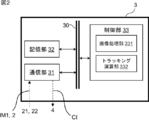
- FIG. 2 is a functional block diagram showing an outline configuration of the information processing device 3.
- the information processing device 3 includes a communication unit 31, a storage unit 32, and a control unit 33, and these components are electrically connected inside the information processing device 3 via a communication bus 30.
- a communication bus 30 a communication bus
- the communication unit 31 is preferably a wired communication means such as USB, IEEE 1394, Thunderbolt, and wired LAN network communication, but wireless LAN network communication, mobile communication such as LTE/3G, Bluetooth (registered trademark) communication, and the like are necessary. May be included. That is, it is more preferable to implement it as a set of these plural communication means.
- the imaging device 2 is configured to be communicable with a predetermined high-speed communication standard. With such a configuration, the image IM (a generic term for the first image IM1 and the second image IM2) can be acquired from the imaging device 2 having a high frame rate.
- the communication unit 31 sets the control information CI, which is information for controlling the angles of the plurality of rotating units 512 in the arm module 51 of the robot hand 5 described later, to a desired angle based on the inverse kinematics. 4 is configured to be transmittable. Further, it is more preferable that the current angle of the rotating unit 512 is configured to be obtainable as information (encoder). With such a configuration, it is possible to perform control such that the pair of grips 521 and 522 of the robot hand 5 are displaced to desired positions in the spatial coordinates.
- the storage unit 32 stores various information defined by the above description. This is, for example, a storage device such as a solid state drive (SSD), or a random access memory (Random Access Memory) that stores temporarily necessary information (arguments, arrays, etc.) related to the calculation of a program. It may be implemented as a memory such as RAM). Also, a combination of these may be used.
- the storage unit 32 stores the image IM captured by the image capturing apparatus 2 and received by the communication unit 31.
- the image IM is array information including pixel information of 8 bits for each of RGB, for example.
- the storage unit 32 also stores a predetermined image processing program executed by the image processing unit 331 (described later) in the control unit 33 on the image IM, and in particular, a predetermined flexible body F executed based on the first image IM1.
- a tracking calculation program for the part Fp is stored.
- the control information CI for controlling the robot hand 5 is sequentially determined by the tracking calculation unit 332 in the control unit 33 by the tracking calculation program.
- the storage unit 32 also stores various programs and the like related to the robot system 1 executed by the control unit 33.
- the control unit 33 processes and controls the overall operation related to the information processing device 3.
- the control unit 33 is, for example, a central processing unit (CPU) (not shown).
- the control unit 33 realizes various functions of the information processing device 3 by reading out a predetermined program stored in the storage unit 32. Specifically, it corresponds to an image processing function for the image IM and a calculation function for tracking the predetermined portion Fp of the flexible body F. That is, the information processing by software (stored in the storage unit 32) is specifically realized by the hardware (control unit 33), and thus can be executed as the image processing unit 331 and the tracking calculation unit 332.
- control unit 33 it is described as a single control unit 33, but it is not limited to this in practice, and a plurality of control units 33 may be provided for each function. It may also be a combination thereof.
- image processing unit 331 and the tracking calculation unit 332 will be described in more detail.
- the image processing unit 331 is one in which information processing by software (stored in the storage unit 32) is specifically realized by hardware (control unit 33).
- the image processing unit 331 is configured to perform predetermined image processing on the image IM transmitted from the imaging device 2 and received by the communication unit 31. More specifically, the image processing unit 331 performs predetermined image processing on the first image IM1 transmitted from the first imaging device 21 and received by the communication unit 31, and in the flexible body F.
- the predetermined portion Fp and the other non-predetermined portion Fq can be distinguished. As a result, the information processing device 3 extracts and recognizes the predetermined part Fp.
- the predetermined part Fp is distinguished from the non-predetermined part Fq when viewed from the first imaging device 21, it is preferable that the predetermined part Fp and the non-predetermined part Fq cannot be distinguished from the human eyes.
- the flexible body F be implemented such that the predetermined portion Fp and the non-predetermined portion Fq appear to be substantially the same color as seen by human eyes. This is because it is considered not appropriate to use a marker or the like that can be visually recognized as a foreign matter by human eyes in towels and sheets where hygiene is important.
- the predetermined portion Fp is a marker sewn on the towel.
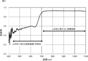
- FIG. 3 shows an example of spectral characteristics of a material that functions as a predetermined portion Fp of the flexible body F.
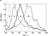
- FIG. 4 shows an example of the spectral characteristics of the preferable image pickup apparatus 2 (especially the first image pickup apparatus 21) corresponding to FIG.
- the material shown in FIG. 3 has a high reflectance in the near infrared region where humans cannot perceive it. Therefore, by adopting the first imaging device 21 as shown in FIG. 4 capable of sensing such a near infrared region, the predetermined portion Fp and the non-predetermined portion Fq are substantially visible to the human eye.
- the first imaging device 21 can image the predetermined portion Fp and the non-predetermined portion Fq of the flexible body F so as to be distinguishable while appearing to have the same color.
- the filter may be configured to cut the visible light region, or may be configured to be able to acquire information regarding both the visible light region and the near infrared region. ..
- image processing may be performed on a predetermined region ROI of a part of the first image IM1.
- the predetermined portion Fp since the tracking of the predetermined portion Fp is performed at a high control rate, the predetermined portion Fp is in the vicinity of a fixed position (for example, the center of the image) of the image IM, and the area near this fixed position is the predetermined area ROI. By doing so, the number of pixels for image processing can be reduced. As a result, the load of image processing calculation in the information processing device 3 can be reduced, and tracking can be performed at a high control rate.
- the image processing unit 331 executes predetermined image processing on the second image IM2 transmitted from the second image pickup device 22 and received by the communication unit 31, so that the user U and the robot hand 5 are connected. Make it distinguishable.
- the information processing device 3 grasps the relative positional relationship between the user U and the robot hand 5 (particularly, the pair of grips 521 and 522). This is performed, for example, by setting a threshold value for a predetermined parameter (brightness or the like) regarding the imaged second image IM2 and converting the imaged second image IM2 into binary.
- the tracking calculation unit 332 is one in which information processing by software (stored in the storage unit 32) is specifically realized by hardware (control unit 33).
- the tracking calculation unit 332 executes a control calculation for aligning the predetermined portion Fp of the flexible body F extracted by the image processing by the image processing unit 331 with the pair of grips 521 and 522 of the robot hand 5.
- the first imaging device 21 is provided on the robot hand 5 so that the relative posture of the robot hand 5 with respect to the pair of grips 521 and 522 is constant regardless of the position of the robot hand 5. Therefore, by displacing the position of the first imaging device 21 so that the predetermined part Fp in the first image IM1 is aligned with the target position, the relative positional relationship with the first imaging device 21 is fixed.
- the pair of grips 521 and 522 can be aligned.
- the tracking calculation unit 332 calculates control information CI relating to these controls, and transmits this to the mechanism control device 4 via the communication unit 31. Then, based on the control information CI, the mechanism control device 4 transmits the control voltage V1 related to the angle control of each rotating unit 512 of the arm module 51 and the control voltage V2 written in the position/posture control of the grip module 52.
- the robot hand 5 it is possible to avoid contact between the robot hand 5 and the user U by using the information on the relative positional relationship between the user U and the robot hand 5 obtained by the second image IM2. It is preferable to give priority. For example, when the distance between the user U and the robot hand 5 is equal to or less than the predetermined value, the alignment (tracking) between the predetermined part Fp and the pair of grips 521 and 522 performed based on the above-described first image IM1. It is advisable to set a condition such as not performing). In other words, in the second image IM2, when the distance between the user U and the robot hand 5 is equal to or less than the specified value, the control for bringing the robot hand 5 closer to the flexible body F may be unexecuted.
- the calculation rate of the tracking calculation unit 332 is as high as the frame rate of the first imaging device 21.
- it is 100 hertz or more, preferably 250 hertz or more, and more preferably 500 hertz or 1000 hertz.
- the lower frame rate of the first imaging device 21 and the lower calculation rate of the tracking calculation unit 332 function as the control rate related to tracking. In other words, by increasing the frame rate and the calculation rate to the same level, it is possible to perform tracking of the predetermined portion Fp in the flexible body F only by feedback control without using prediction.
- the mechanism control device 4 includes a storage unit and a control unit (not shown).
- the storage unit is, for example, a storage device such as a solid state drive (SSD), or a random access memory (Random Access Memory) that stores temporarily necessary information (arguments, arrays, etc.) related to program calculation. : RAM) and the like. Also, a combination of these may be used.
- the control unit may be implemented as, for example, a central processing unit (CPU). The control unit realizes various functions related to control of the robot hand 5 by reading out a predetermined program stored in the storage unit.
- the mechanism control device 4 is a wired communication means such as USB, IEEE1394, Thunderbolt, and wired LAN network communication, or wireless LAN network communication, mobile communication such as LTE/3G, and wireless communication such as Bluetooth (registered trademark) communication.
- the device may be provided as necessary so that it can be connected to an external device.
- the robot hand 5 is configured to be capable of high-speed communication according to the dedicated communication standard.
- the mechanism control device 4 is configured such that a control unit (not shown) can control the angle of each rotating unit 512 of the arm module 51 constituting the robot hand 5 and the position/posture of the grip module 52. To be done.
- the mechanism control device 4 When the mechanism control device 4 is connected to the information processing device 3 and receives the control information CI transmitted from the communication unit 31 in the information processing device 3, the mechanism control device 4 applies the control voltages V1 and V2 to the robot hand 5 based on the control information CI. Send power.
- control for example, PD control, PI control, PID control, or the like can be appropriately adopted.
- Each coefficient related to the control may be included in the control information CI, or may be determined by the mechanism control device 4 based on the control information CI. In addition, a preferable value may be set as needed.
- the control rate of the mechanism control device 4 (the drive rate of the robot hand 5) is as high as the frame rate of the first imaging device 21 and the calculation rate of the information processing device 3.
- it is 100 hertz or more, preferably 250 hertz or more, and more preferably 500 hertz or 1000 hertz.
- the operation system used for the mechanism control device 4 is preferably a real-time operation system.
- the robot hand 5 includes an arm module 51 and a grip module 52 attached to the tip of the arm module 51.
- the shapes and structures of the arm module 51 and the grip module 52 are merely examples and are not particularly limited.
- the arm module 51 includes a plurality of arm portions 511 and a plurality of rotating portions 512 that function as joints of the arm portions 511 or as connection points with the grip module 52.
- Each rotating unit 512 is controlled to have a desired angle by the control voltage V1 transmitted from the mechanism control device 4. Further, as a result, the position/posture of a later-described grip module 52 connected to the arm module 51 is controlled.
- the grip module 52 is connected to the arm module 51 via one rotating portion 512.
- the grip module 52 has a pair of grips 521 and 522 at its tip.
- the grip module 52 is configured to be able to control the relative positions of the pair of grip portions 521 and 522 within the grip module 52.
- the pair of grips 521 and 522 are configured to grip a predetermined portion Fp of the flexible body F which the user U grips with his or her hand UH.
- the grip module 52 is provided with the first imaging device 21. More specifically, the first imaging device 21 is provided so that the relative posture with respect to the grips 521 and 522 is constant regardless of the position of the robot hand 5.
- the relative positions of the pair of grips 521 and 522 in the robot hand 5 are controlled as desired by the control voltage V2 transmitted by the mechanism control device 4.
- the movable stroke of the pair of grip portions 521 and 522 by controlling the arm module 51 is wide, the movable stroke of the pair of grip portions 521 and 522 by controlling the grip module 52 is equal to the movable stroke of the arm module 51. It is preferable to be limited to a narrower range than the above.
- the drive rate of the arm module 51 may be lower than the drive rate of the grip module 52. That is, in controlling the pair of grips 521 and 522 to desired positions, rough alignment is performed by the control of the arm module 51 (low frequency control), and further fine adjustment of the position is controlled by the grip module 52 (high frequency control). ).
- the drive rate of the arm module 51 is defined as f_3 and the drive rate of the gripping module 52 is defined as f_4.
- the arm module 51 which is controlled at a low drive rate, may be controlled in the direction opposite to the direction in which the user U is located, if necessary.
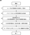
- FIG. 5 shows an operation flow of the robot system 1.
- Step S1 The user U presents the flexible body F to the robot hand 5 while holding the non-predetermined part Fq of the flexible body F with the hand UH (continues to step S2).
- Step S2 The image processing unit 331 in the information processing device 3 determines a threshold value of a predetermined parameter (brightness or the like) for the first image IM1 captured by the first image capturing device 21 and binary-processes the first image IM1. Turn into. As a result, the predetermined portion Fp of the flexible body F is extracted (continue to step S3).
- Step S3 The tracking calculation unit 332 of the information processing device 3 determines the position based on the first image IM1 that has been binarized in step S2, based on the positional relationship between the predetermined portion Fp and the pair of grips 521 and 522 (the positional relationship between the first image pickup device 21). Is known), and calculates the distance to. Then, the control information CI that makes the distance closer to 0 is calculated (continuation to step S4).
- Step S4 The mechanism control device 4 transmits the control voltages V1 and V2 to the robot hand 5 based on the control information CI calculated in step S3. As a result, the angles of the rotary parts 512 in the arm module 51 and the position/posture of the grip module 52 are controlled as desired (continuation to step S5).
- Step S5 By repeating steps S2 to S4, the pair of grips 521 and 522 approach the flexible body F, and the pair of grips 521 and 522 receive the flexible body F from the user U, whereby the delivery task is completed.
- the control for maintaining the distance between the user U and the robot hand 5 is preferentially executed instead of steps S2 to S4. It After the delivery is completed, the robot system 1 conveys the flexible body F to an appropriate position, so that it is possible to assist the transportation line of the flexible body F which has been conventionally performed by a human.
- Modifications Section 3 describes modifications of the robot system 1 according to the present embodiment. That is, the robot system 1 may be further creatively devised in the following manner.
- the description will be made assuming that the predetermined portion Fp of the flexible body F is extracted in the first image IM1 and the relative positional relationship between the user U and the robot hand 5 is recognized in the second image IM2.
- the relative positional relationship between the user U and the robot hand 5 can be grasped in the first image IM1
- a predetermined portion Fp of the flexible body F may be extracted from the second image IM2 and used for position control of the pair of grips 521 and 522.
- the first image pickup device 21 and the second image pickup device 22 are adopted as the image pickup device 2, but either one of them may be adopted.
- both the predetermined portion Fp of the flexible body F and the relative positional relationship between the user U and the robot hand 5 can be grasped and recognized from the image IM obtained by either one. I want to.
- the positions of the pair of grips 521 and 522 are arranged to be known, but in order to further improve the accuracy, the tips of the pair of grips 521 and 522 are arranged.
- a marker (not shown) may be provided so that the detailed positions of the pair of grips 521 and 522 can be extracted from the first image IM1.
- the information processing device 3 and the mechanism control device 4 may be implemented as one information processing device without being divided.
- a separate sensor may be added in addition to the imaging device 2.
- a force sensor is considered to be effective.
- a force sensor is introduced to acquire information such as a contact force, and based on this, the tracking calculation unit 332 determines the safety.
- the control information CI may be calculated in consideration of the above.
- the robot system 1 includes a robot hand 5, an imaging device 2, and an information processing device (the information processing device 3 and the mechanism control device 4).
- the robot hand 5 is displaced within a predetermined range in spatial coordinates,
- the flexible body F grasped by a human (user U) is configured to be graspable, and the imaging device 2 is configured to be able to capture the flexible body F and the human (user U) as an image IM.
- the processing device 3 and the mechanism control device 4) recognize the position of the flexible body F and the position of the human (user U) based on the image IM, and the robot hand 5 contacts the human (user U) in a non-contact manner.
- the position and orientation of the robot hand 5 are controllable so that the flexible body F can be received from a human (user U).
- Robot system 2 Imaging device 21: First imaging device 22: Second imaging device 3: Information processing device 30: Communication bus 31: Communication unit 32: Storage unit 33: Control unit 331: Image processing unit 332: Tracking calculation unit 4: Mechanism control device 5: Robot hand 51: Arm module 511: Arm unit 512: Rotating unit 52: Gripping module 521: Gripping unit 522: Gripping unit CI: Control information F: Flexible body Fp: Predetermined portion Fq: Non-predetermined part IM: Image IM1: First image IM2: Second image U: User UH: Hand V1: Control voltage V2: Control voltage
Landscapes
- Engineering & Computer Science (AREA)
- Human Computer Interaction (AREA)
- Robotics (AREA)
- Mechanical Engineering (AREA)
- Manipulator (AREA)
Abstract
【課題】ヒトに対する安全性を維持しながら、柔軟体を取り扱う搬送ラインに使用可能なロボットシステムを提供すること。 【解決手段】本発明によれば、ロボットシステムであって、ロボットハンドと、撮像装置と、情報処理装置とを備え、前記ロボットハンドは、空間座標における所定の範囲内を変位し、ヒトが把持している柔軟体を把持可能に構成され、前記撮像装置は、前記柔軟体と前記ヒトとを画像として撮像可能に構成され、前記情報処理装置は、前記画像に基づいて、前記柔軟体の位置と前記ヒトの位置とを認識し、前記ロボットハンドが、前記ヒトと非接触に且つ前記柔軟体を前記ヒトから受け取ることができるように、前記ロボットハンドの位置・姿勢を制御可能に構成される、ロボットシステムが提供される。
Description
本発明は、ロボットシステムに関する。
産業界や医療業界では、ヒトに代わってロボットが用いられることがある。例えば、産業界では、ロボットを用いて搬送、ピックアップ等のタスクを実施することが行われている。特許文献1には剛体であるワークの搬送を行うワーク搬送システムが開示されている。
一方で、ロボットが不得意なタスクも存在し、このようなタスクが含まれるラインでは、ヒトの手によってなされることとなる。例えば、特許文献1に開示されるようなシステムでは、タオルやシーツ等の柔軟体の搬送ラインに使用することが難しいと考えられる。なぜなら、柔軟体は逐次その形状が変化し、また無地のものが多いため、ロボットがその特徴と捉えにくいからである。さらにロボットが苦手なタスクだけをヒトの手によって行い、それ以外のタスクをロボットによって行うことも考えられるが、ロボットとヒトとが近接して作業をするには安全面の問題を考慮しなければならない。
本発明は、かかる事情を鑑みてなされたものであり、ヒトに対する安全性を維持しながら、柔軟体を取り扱う搬送ラインに使用可能なロボットシステムを提供することを目的とする。
本発明によれば、ロボットシステムであって、ロボットハンドと、撮像装置と、情報処理装置とを備え、前記ロボットハンドは、空間座標における所定の範囲内を変位し、ヒトが把持している柔軟体を把持可能に構成され、前記撮像装置は、前記柔軟体と前記ヒトとを画像として撮像可能に構成され、前記情報処理装置は、前記画像に基づいて、前記柔軟体の位置と前記ヒトの位置とを認識し、前記ロボットハンドが、前記ヒトと非接触に且つ前記柔軟体を前記ヒトから受け取ることができるように、前記ロボットハンドの位置・姿勢を制御可能に構成される、ロボットシステムが提供される。
本発明に係るロボットシステムは、撮像装置が、柔軟体とヒトとを画像として撮像し、情報処理装置が、かかる画像に基づいて柔軟体の所定部位の位置とヒトの位置とを認識する。そして、情報処理装置によって、ロボットハンドがヒトと非接触に且つ柔軟体をヒトから受け取ることができるように、ロボットハンドの位置・姿勢が制御される。このような構成によって、ヒトに対する安全性を維持しながら、ヒトとともに柔軟体を取り扱う搬送ラインに組み込むことができる、という効果を奏する。換言すると、ヒトへの物理的な危険性を限りなく小さくすることができる。
以下、図面を用いて本発明の実施形態について説明する。以下に示す実施形態中で示した各種特徴事項は、互いに組み合わせ可能である。特に、本明細書において「部」とは、例えば、広義の回路によって実施されるハードウェア資源と、これらのハードウェア資源によって具体的に実現されうるソフトウェアの情報処理とを合わせたものも含みうる。また、本実施形態においては様々な情報を取り扱うが、これら情報は、0又は1で構成される2進数のビット集合体として信号値の高低によって表され、広義の回路上で通信・演算が実行されうる。
また、広義の回路とは、回路(Circuit)、回路類(Circuitry)、プロセッサ(Processor)、及びメモリ(Memory)等を少なくとも適当に組み合わせることによって実現される回路である。すなわち、特定用途向け集積回路(Application Specific Integrated Circuit:ASIC)、プログラマブル論理デバイス(例えば、単純プログラマブル論理デバイス(Simple Programmable Logic Device:SPLD)、複合プログラマブル論理デバイス(Complex Programmable Logic Device:CLPD)、及びフィールドプログラマブルゲートアレイ(Field Programmable Gate Array:FPGA))等を含むものである。
1.全体構成
第1節では、本実施形態に係るロボットシステム1の全体構成を説明する。図1は、本実施形態に係るロボットシステム1の構成概要を示す図である。ロボットシステム1は、撮像装置2と、情報処理装置3と、機構制御装置4と、ロボットハンド5とを備え、これらが電気的に接続されたシステムである。以下各構成要素についてさらに詳述する。
第1節では、本実施形態に係るロボットシステム1の全体構成を説明する。図1は、本実施形態に係るロボットシステム1の構成概要を示す図である。ロボットシステム1は、撮像装置2と、情報処理装置3と、機構制御装置4と、ロボットハンド5とを備え、これらが電気的に接続されたシステムである。以下各構成要素についてさらに詳述する。
1.1 撮像装置2
撮像装置2は、外界の情報を画像として取得可能に構成される、いわゆるビジョンセンサ(カメラ)であり、特に高速ビジョンと称するフレームレートが高いものが採用されることが好ましい。フレームレートは、例えば、100fps以上であり、好ましくは、250fps以上であり、更に好ましくは500fps又は1000fpsである。具体的には例えば、100、200、300、400、500、600、700、800、900、1000、1100、1200、1300、1400、1500、1600、1700、1800、1900、2000fps(ヘルツ)であり、ここで例示した数値の何れか2つの間の範囲内であってもよい。より具体的には、撮像装置2は、第1の撮像装置21及び第2の撮像装置22からなる。
撮像装置2は、外界の情報を画像として取得可能に構成される、いわゆるビジョンセンサ(カメラ)であり、特に高速ビジョンと称するフレームレートが高いものが採用されることが好ましい。フレームレートは、例えば、100fps以上であり、好ましくは、250fps以上であり、更に好ましくは500fps又は1000fpsである。具体的には例えば、100、200、300、400、500、600、700、800、900、1000、1100、1200、1300、1400、1500、1600、1700、1800、1900、2000fps(ヘルツ)であり、ここで例示した数値の何れか2つの間の範囲内であってもよい。より具体的には、撮像装置2は、第1の撮像装置21及び第2の撮像装置22からなる。
<第1の撮像装置21>
第1の撮像装置21は、ロボットハンド5に設けられる。より詳細には、第1の撮像装置21は、ロボットハンド5における一対の把持部521,522との相対的な姿勢がロボットハンド5の位置に関わらず一定であるように設けられる。ロボットハンド5の変位に伴ってその撮像範囲が変化し、特に、柔軟体Fの所定部位Fpを第1の画像IM1として撮像可能に構成される。そして、柔軟体Fが変位・変形した場合においても、第1の画像IM1中における柔軟体Fの所定部位Fpの位置を高い時間分解能で逐次把握し、所定部位Fpが第1の画像IM1における規定の位置に来るようにロボットハンド5が制御される。
第1の撮像装置21は、ロボットハンド5に設けられる。より詳細には、第1の撮像装置21は、ロボットハンド5における一対の把持部521,522との相対的な姿勢がロボットハンド5の位置に関わらず一定であるように設けられる。ロボットハンド5の変位に伴ってその撮像範囲が変化し、特に、柔軟体Fの所定部位Fpを第1の画像IM1として撮像可能に構成される。そして、柔軟体Fが変位・変形した場合においても、第1の画像IM1中における柔軟体Fの所定部位Fpの位置を高い時間分解能で逐次把握し、所定部位Fpが第1の画像IM1における規定の位置に来るようにロボットハンド5が制御される。
<第2の撮像装置22>
第2の撮像装置22は、ロボットハンド5とは異なる位置に設けられる。より詳細には、第2の撮像装置22は、ロボットハンド5の変位に関わらず規定の撮像範囲を撮像するように構成される。特に、ロボットハンド5に近接して作業をすることとなるユーザUを第2の画像IM2として撮像可能に構成される。ユーザUがロボットハンド5に近接して作業をする場合において、接触による事故に注意する必要がある。具体的には例えば、ユーザUが把持している柔軟体Fをロボットハンド5に受け渡すタスクを行うにあたり、ユーザUの安全性を鑑みて、ユーザUとロボットハンド5との接触を回避する必要がある。本実施形態に係るロボットシステム1では、第2の画像IM2に基づいて、ユーザUとロボットハンド5との相対的位置を高い時間分解能で逐次把握し、ロボットハンド5がユーザUに接触しないように制御がなされる。
第2の撮像装置22は、ロボットハンド5とは異なる位置に設けられる。より詳細には、第2の撮像装置22は、ロボットハンド5の変位に関わらず規定の撮像範囲を撮像するように構成される。特に、ロボットハンド5に近接して作業をすることとなるユーザUを第2の画像IM2として撮像可能に構成される。ユーザUがロボットハンド5に近接して作業をする場合において、接触による事故に注意する必要がある。具体的には例えば、ユーザUが把持している柔軟体Fをロボットハンド5に受け渡すタスクを行うにあたり、ユーザUの安全性を鑑みて、ユーザUとロボットハンド5との接触を回避する必要がある。本実施形態に係るロボットシステム1では、第2の画像IM2に基づいて、ユーザUとロボットハンド5との相対的位置を高い時間分解能で逐次把握し、ロボットハンド5がユーザUに接触しないように制御がなされる。
ここで、逐次形状が変化する柔軟体Fを撮像するための第1の撮像装置21のフレームレートは、特に高いことが好ましい。したがって、第1の撮像装置21のフレームレートをf_1とし、第2の撮像装置22のフレームレートをf_2と定義すると、f_1≧f_2を満たすように実施してもよい。
1.2 情報処理装置3
図2は、情報処理装置3の構成概要を示す機能ブロック図である。情報処理装置3は、通信部31と、記憶部32と、制御部33とを有し、これらの構成要素が情報処理装置3の内部において通信バス30を介して電気的に接続されている。以下、各構成要素についてさらに説明する。
図2は、情報処理装置3の構成概要を示す機能ブロック図である。情報処理装置3は、通信部31と、記憶部32と、制御部33とを有し、これらの構成要素が情報処理装置3の内部において通信バス30を介して電気的に接続されている。以下、各構成要素についてさらに説明する。
<通信部31>
通信部31は、USB、IEEE1394、Thunderbolt、有線LANネットワーク通信等といった有線型の通信手段が好ましいものの、無線LANネットワーク通信、LTE/3G等のモバイル通信、Bluetooth(登録商標)通信等を必要に応じて含めてもよい。すなわち、これら複数の通信手段の集合として実施することがより好ましい。特に、撮像装置2とは、所定の高速通信規格において通信可能に構成されることが好ましい。このような構成により、高いフレームレートを有する撮像装置2から画像IM(第1の画像IM1,第2の画像IM2の総称)を取得することができる。また、通信部31は、後述のロボットハンド5のアームモジュール51における複数の回転部512の角度を逆運動学に基づいて所望の角度に制御するための情報である制御情報CIを、機構制御装置4に送信可能に構成される。また、現在の回転部512の角度が情報として取得可能(エンコーダ)に構成されると、さらに好ましい。このような構成により、ロボットハンド5における一対の把持部521,522を、空間座標中の所望の位置に変位させるような制御が可能となる。
通信部31は、USB、IEEE1394、Thunderbolt、有線LANネットワーク通信等といった有線型の通信手段が好ましいものの、無線LANネットワーク通信、LTE/3G等のモバイル通信、Bluetooth(登録商標)通信等を必要に応じて含めてもよい。すなわち、これら複数の通信手段の集合として実施することがより好ましい。特に、撮像装置2とは、所定の高速通信規格において通信可能に構成されることが好ましい。このような構成により、高いフレームレートを有する撮像装置2から画像IM(第1の画像IM1,第2の画像IM2の総称)を取得することができる。また、通信部31は、後述のロボットハンド5のアームモジュール51における複数の回転部512の角度を逆運動学に基づいて所望の角度に制御するための情報である制御情報CIを、機構制御装置4に送信可能に構成される。また、現在の回転部512の角度が情報として取得可能(エンコーダ)に構成されると、さらに好ましい。このような構成により、ロボットハンド5における一対の把持部521,522を、空間座標中の所望の位置に変位させるような制御が可能となる。
<記憶部32>
記憶部32は、前述の記載により定義される様々な情報を記憶する。これは、例えばソリッドステートドライブ(Solid State Drive:SSD)等のストレージデバイスとして、あるいは、プログラムの演算に係る一時的に必要な情報(引数、配列等)を記憶するランダムアクセスメモリ(Random Access Memory:RAM)等のメモリとして実施されうる。また、これらの組合せであってもよい。特に、記憶部32は、撮像装置2によって撮像され、且つ通信部31が受信した画像IMを記憶する。画像IMは、例えばRGB各8ビットのピクセル情報を具備する配列情報である。また、記憶部32は、制御部33における画像処理部331(後述)が画像IMに対して実行する所定の画像処理プログラムと、特に第1の画像IM1に基づいて実行される柔軟体Fの所定部位Fpのトラッキング演算プログラムとを記憶する。かかるトラッキング演算プログラムによってロボットハンド5を制御するための制御情報CIが制御部33におけるトラッキング演算部332によって逐次決定される。また、記憶部32は、これ以外にも制御部33によって実行されるロボットシステム1に係る種々のプログラム等を記憶している。
記憶部32は、前述の記載により定義される様々な情報を記憶する。これは、例えばソリッドステートドライブ(Solid State Drive:SSD)等のストレージデバイスとして、あるいは、プログラムの演算に係る一時的に必要な情報(引数、配列等)を記憶するランダムアクセスメモリ(Random Access Memory:RAM)等のメモリとして実施されうる。また、これらの組合せであってもよい。特に、記憶部32は、撮像装置2によって撮像され、且つ通信部31が受信した画像IMを記憶する。画像IMは、例えばRGB各8ビットのピクセル情報を具備する配列情報である。また、記憶部32は、制御部33における画像処理部331(後述)が画像IMに対して実行する所定の画像処理プログラムと、特に第1の画像IM1に基づいて実行される柔軟体Fの所定部位Fpのトラッキング演算プログラムとを記憶する。かかるトラッキング演算プログラムによってロボットハンド5を制御するための制御情報CIが制御部33におけるトラッキング演算部332によって逐次決定される。また、記憶部32は、これ以外にも制御部33によって実行されるロボットシステム1に係る種々のプログラム等を記憶している。
<制御部33>
制御部33は、情報処理装置3に関連する全体動作の処理・制御を行う。制御部33は、例えば不図示の中央処理装置(Central Processing Unit:CPU)である。制御部33は、記憶部32に記憶された所定のプログラムを読み出すことによって、情報処理装置3に係る種々の機能を実現する。具体的には画像IMに対する画像処理機能、柔軟体Fにおける所定部位Fpのトラッキングに関する演算機能が該当する。すなわち、ソフトウェア(記憶部32に記憶されている)による情報処理がハードウェア(制御部33)によって具体的に実現されることで、画像処理部331及びトラッキング演算部332として実行されうる。なお、図3においては、単一の制御部33として表記されているが、実際はこれに限るものではなく、機能ごとに複数の制御部33を有するように実施してもよい。またそれらの組合せであってもよい。以下、画像処理部331、及びトラッキング演算部332についてさらに詳述する。
制御部33は、情報処理装置3に関連する全体動作の処理・制御を行う。制御部33は、例えば不図示の中央処理装置(Central Processing Unit:CPU)である。制御部33は、記憶部32に記憶された所定のプログラムを読み出すことによって、情報処理装置3に係る種々の機能を実現する。具体的には画像IMに対する画像処理機能、柔軟体Fにおける所定部位Fpのトラッキングに関する演算機能が該当する。すなわち、ソフトウェア(記憶部32に記憶されている)による情報処理がハードウェア(制御部33)によって具体的に実現されることで、画像処理部331及びトラッキング演算部332として実行されうる。なお、図3においては、単一の制御部33として表記されているが、実際はこれに限るものではなく、機能ごとに複数の制御部33を有するように実施してもよい。またそれらの組合せであってもよい。以下、画像処理部331、及びトラッキング演算部332についてさらに詳述する。
[画像処理部331]
画像処理部331は、ソフトウェア(記憶部32に記憶されている)による情報処理がハードウェア(制御部33)によって具体的に実現されているものである。画像処理部331は、撮像装置2から送信され且つ通信部31によって受信された画像IMに対して、所定の画像処理を実行するように構成される。より具体的には、画像処理部331は、第1の撮像装置21から送信され且つ通信部31によって受信された第1の画像IM1に対して、所定の画像処理を実行し、柔軟体Fにおける所定部位Fpとそれ以外の非所定部位Fqとを区別可能にする。その結果、情報処理装置3が所定部位Fpを抽出・認識することとなる。
画像処理部331は、ソフトウェア(記憶部32に記憶されている)による情報処理がハードウェア(制御部33)によって具体的に実現されているものである。画像処理部331は、撮像装置2から送信され且つ通信部31によって受信された画像IMに対して、所定の画像処理を実行するように構成される。より具体的には、画像処理部331は、第1の撮像装置21から送信され且つ通信部31によって受信された第1の画像IM1に対して、所定の画像処理を実行し、柔軟体Fにおける所定部位Fpとそれ以外の非所定部位Fqとを区別可能にする。その結果、情報処理装置3が所定部位Fpを抽出・認識することとなる。
これは例えば、撮像された第1の画像IM1を、画像に関する所定のパラメータ(明度等)にしきい値を決めてバイナリ化することで実施される。また、第1の撮像装置21から見ると、所定部位Fpと非所定部位Fqとが区別できるものの、ヒトの目から見ると、所定部位Fpと非所定部位Fqとが区別できないことが好ましい。換言すると、柔軟体Fは、所定部位Fpと非所定部位Fqとがヒトの目から見て略同じ色に見えるように実施されることが好ましい。なぜなら、衛生面を重視するタオルやシーツにおいて、ヒトの目から異物のように視認されるマーカー等を採用することは適切ではないと考えられるからである。すなわち、このような効果を有するように、所定部位Fpと非所定部位Fqとに分光特性の違いを設ける。柔軟体Fがタオルであるとすれば、所定部位Fpとは、かかるタオルに縫い付けられたマーカーである。
図3は、柔軟体Fの所定部位Fpとして機能する素材の分光特性の一例を示している。また、図4は、図3に対応する好ましい撮像装置2(特に第1の撮像装置21)の分光特性の一例を示している。図3に示される素材は、ヒトが感知できない近赤外領域において高い反射率を有する。このため、このような近赤外領域を感知可能な図4に示されるような第1の撮像装置21を採用することで、所定部位Fpと非所定部位Fqとがヒトの目から見て略同じ色に見えつつ、且つ第1の撮像装置21が柔軟体Fにおける所定部位Fpと非所定部位Fqとを区別可能に撮像することができる。第1の撮像装置21を使用するにあたり、フィルタによって可視光領域をカットするように構成されてもよいし、可視光及び近赤外の両方の領域に係る情報を取得可能に構成されてもよい。
さらに、第1の画像IM1の一部の所定領域ROIに対して画像処理を行うように実施してもよい。特に、所定部位Fpのトラッキングを高い制御レートにて行うため、所定部位Fpは、画像IMの決まった位置(例えば画像中心)の近傍にあることとなり、この決まった位置の近傍領域を所定領域ROIとすることで、画像処理をするピクセル数を削減することができる。これにより、情報処理装置3における画像処理演算の負荷を小さくすることができ、高い制御レートでのトラッキングを実施することができる。
さらに、画像処理部331は、第2の撮像装置22から送信され且つ通信部31によって受信された第2の画像IM2に対して、所定の画像処理を実行し、ユーザUとロボットハンド5とを区別可能にする。その結果、情報処理装置3がユーザUとロボットハンド5(特に一対の把持部521,522)との相対的な位置関係を把握することとなる。これは例えば、撮像された第2の画像IM2を、画像に関する所定のパラメータ(明度等)にしきい値を決めてバイナリ化することで実施される。
[トラッキング演算部332]
トラッキング演算部332は、ソフトウェア(記憶部32に記憶されている)による情報処理がハードウェア(制御部33)によって具体的に実現されているものである。トラッキング演算部332は、画像処理部331による画像処理によって抽出された柔軟体Fにおける所定部位Fpをロボットハンド5における一対の把持部521,522に位置合わせするような制御演算を実行する。
トラッキング演算部332は、ソフトウェア(記憶部32に記憶されている)による情報処理がハードウェア(制御部33)によって具体的に実現されているものである。トラッキング演算部332は、画像処理部331による画像処理によって抽出された柔軟体Fにおける所定部位Fpをロボットハンド5における一対の把持部521,522に位置合わせするような制御演算を実行する。
前述の通り、第1の撮像装置21は、ロボットハンド5における一対の把持部521,522との相対的な姿勢がロボットハンド5の位置に関わらず一定であるように、ロボットハンド5上に設けられているので、第1の画像IM1における所定部位Fpを目標位置に合わせるように第1の撮像装置21の位置を変位させることで、第1の撮像装置21と相対的な位置関係が固定された一対の把持部521,522の位置合わせを行うことができる。
すなわち、トラッキング演算部332は、これらの制御に係る制御情報CIを演算し、通信部31を介してこれを機構制御装置4に送信する。そして、制御情報CIに基づいて、機構制御装置4がアームモジュール51の各回転部512の角度制御に係る制御電圧V1及び把持モジュール52の位置・姿勢制御に書かう制御電圧V2を送電する。
ただし、かかるトラッキングにあたっては、第2の画像IM2によって得られたユーザUとロボットハンド5との相対的な位置関係の情報を用いて、ロボットハンド5とユーザUとの接触が回避されることを優先することが好ましい。例えば、ユーザUとロボットハンド5との距離が既定値以下である場合には、前述の第1の画像IM1に基づいて行われる所定部位Fpと一対の把持部521,522との位置合わせ(トラッキング)を行わないといった条件を設けるとよい。換言すると、第2の画像IM2において、ユーザUとロボットハンド5との距離が規定値以下である場合は、ロボットハンド5を柔軟体Fに近づける制御を不実行とすればよい。
なお、トラッキング演算部332の演算レートは、第1の撮像装置21のフレームレート同様、高いことが好ましい。例えば、100ヘルツ以上であり、好ましくは、250ヘルツ以上であり、更に好ましくは500ヘルツ又は1000ヘルツである。具体的には例えば、100、200、300、400、500、600、700、800、900、1000、1100、1200、1300、1400、1500、1600、1700、1800、1900、2000ヘルツであり、ここで例示した数値の何れか2つの間の範囲内であってもよい。
ロボットシステム1全体としては、第1の撮像装置21のフレームレート及びトラッキング演算部332の演算レートの低い方が、トラッキングに係る制御レートとして機能する。換言すると、当該フレームレート及び演算レートを同程度に高くすることで、予測を用いずにフィードバック制御のみで柔軟体Fにおける所定部位Fpのトラッキングを実施することができる。
1.3 機構制御装置4
機構制御装置4は、不図示の記憶部や制御部を備えている。記憶部は、例えばソリッドステートドライブ(Solid State Drive:SSD)等のストレージデバイスとして、或いは、プログラムの演算に係る一時的に必要な情報(引数、配列等)を記憶するランダムアクセスメモリ(Random Access Memory:RAM)等のメモリとして実施されうる。また、これらの組合せであってもよい。制御部は、例えば中央処理装置(Central Processing Unit:CPU)として実施されうる。制御部は、記憶部に記憶された所定のプログラムを読み出すことによって、ロボットハンド5の制御に関する種々の機能を実現する。
機構制御装置4は、不図示の記憶部や制御部を備えている。記憶部は、例えばソリッドステートドライブ(Solid State Drive:SSD)等のストレージデバイスとして、或いは、プログラムの演算に係る一時的に必要な情報(引数、配列等)を記憶するランダムアクセスメモリ(Random Access Memory:RAM)等のメモリとして実施されうる。また、これらの組合せであってもよい。制御部は、例えば中央処理装置(Central Processing Unit:CPU)として実施されうる。制御部は、記憶部に記憶された所定のプログラムを読み出すことによって、ロボットハンド5の制御に関する種々の機能を実現する。
また、機構制御装置4は、USB、IEEE1394、Thunderbolt、有線LANネットワーク通信等といった有線型の通信手段又は、無線LANネットワーク通信、LTE/3G等のモバイル通信、Bluetooth(登録商標)通信等の無線通信手段を必要に応じて有することで、外部機器と接続可能に構成されるとよい。特に、ロボットハンド5とは、専用通信規格において高速通信可能に構成されることが好ましい。
より具体的には、機構制御装置4は、不図示の制御部によって、ロボットハンド5を構成するアームモジュール51の各回転部512の角度と、把持モジュール52の位置・姿勢とを制御可能に構成される。機構制御装置4は、情報処理装置3と接続され、情報処理装置3における通信部31から送信された制御情報CIを受信すると、かかる制御情報CIに基づいて制御電圧V1,V2をロボットハンド5に送電する。このような制御としては、例えばPD制御、PI制御、又はPID制御等が適宜採用されうる。制御に係る各係数は、制御情報CIに含まれるように実施してもよいし、制御情報CIに基づいて機構制御装置4によって決定されるように実施してもよい。また、必要に応じて好ましい値を設定すればよい。
特に、機構制御装置4の制御レート(ロボットハンド5の駆動レート)は、第1の撮像装置21のフレームレート及び情報処理装置3の演算レート同様、高いことが好ましい。例えば、100ヘルツ以上であり、好ましくは、250ヘルツ以上であり、更に好ましくは500ヘルツ又は1000ヘルツである。具体的には例えば、100、200、300、400、500、600、700、800、900、1000、1100、1200、1300、1400、1500、1600、1700、1800、1900、2000ヘルツであり、ここで例示した数値の何れか2つの間の範囲内であってもよい。また、ロボットシステム1の系全体としてのレイテンシを小さくすべく、機構制御装置4に使用されるオペレーション・システムは、リアルアイムオペレーション・システムであることが好ましい。
1.4 ロボットハンド5
ロボットハンド5は、アームモジュール51と、アームモジュール51の先端に取り付けられた把持モジュール52とから構成される。なお、アームモジュール51及び把持モジュール52の形状や構造については、あくまでも一例であり特に限定されるものではない。
ロボットハンド5は、アームモジュール51と、アームモジュール51の先端に取り付けられた把持モジュール52とから構成される。なお、アームモジュール51及び把持モジュール52の形状や構造については、あくまでも一例であり特に限定されるものではない。
<アームモジュール51>
アームモジュール51は、複数のアーム部511と、アーム部511の関節として又は把持モジュール52との接続箇所として機能する複数の回転部512とを備える。各回転部512は、機構制御装置4により送電された制御電圧V1によって所望の角度となるように制御される。また、これにより、アームモジュール51に接続された後述の把持モジュール52の位置・姿勢が制御される。
アームモジュール51は、複数のアーム部511と、アーム部511の関節として又は把持モジュール52との接続箇所として機能する複数の回転部512とを備える。各回転部512は、機構制御装置4により送電された制御電圧V1によって所望の角度となるように制御される。また、これにより、アームモジュール51に接続された後述の把持モジュール52の位置・姿勢が制御される。
<把持モジュール52>
把持モジュール52は、アームモジュール51と1つの回転部512を介して接続されている。把持モジュール52は、その先端に一対の把持部521,522を有する。特に、把持モジュール52は、当該把持モジュール52内での一対の把持部521,522の相対位置を制御可能に構成される。一対の把持部521,522は、ユーザUが自身の手UHで把持している柔軟体Fの所定部位Fpを把持するように構成される。また、把持モジュール52には、第1の撮像装置21が設けられる。より詳細には、第1の撮像装置21は、把持部521,522との相対的な姿勢がロボットハンド5の位置に関わらず一定であるように設けられる。ロボットハンド5における一対の把持部521,522の相対位置は、機構制御装置4により送電された制御電圧V2によって所望に制御される。
把持モジュール52は、アームモジュール51と1つの回転部512を介して接続されている。把持モジュール52は、その先端に一対の把持部521,522を有する。特に、把持モジュール52は、当該把持モジュール52内での一対の把持部521,522の相対位置を制御可能に構成される。一対の把持部521,522は、ユーザUが自身の手UHで把持している柔軟体Fの所定部位Fpを把持するように構成される。また、把持モジュール52には、第1の撮像装置21が設けられる。より詳細には、第1の撮像装置21は、把持部521,522との相対的な姿勢がロボットハンド5の位置に関わらず一定であるように設けられる。ロボットハンド5における一対の把持部521,522の相対位置は、機構制御装置4により送電された制御電圧V2によって所望に制御される。
ここで、アームモジュール51を制御することによる一対の把持部521,522の可動ストロークは、広範囲にわたるものの、把持モジュール52を制御することによる一対の把持部521,522の可動ストロークは、アームモジュール51に比して狭い範囲に限定されることが好ましい。また、アームモジュール51の駆動レートは、把持モジュール52の駆動レートに比べて低くてもよい。すなわち、一対の把持部521,522を所望の位置に制御するにあたり、大まかな位置合わせをアームモジュール51の制御(低周波制御)によって行い、さらなる位置の微調整を把持モジュール52の制御(高周波制御)によって行うようにしてもよい。つまり、前述の機構制御装置4の制御レート(ロボットハンド5の駆動レート)についてさらに詳述するならば、アームモジュール51の駆動レートをf_3とし、把持モジュール52の駆動レートをf_4と定義すると、f_3≦f_4を満たすように実施してもよい。かかる場合、安全面を考慮してユーザUとロボットハンド5との接触を回避するにあたり、まずは高い駆動レートで制御可能な把持モジュール52をユーザUの位置する方向と逆方向に制御することが好ましい。その後、必要に応じて低い駆動レートで制御されるアームモジュール51をユーザUの位置する方向と逆方向に制御すればよい。
2.ロボットシステム1の動作フロー
第2節では、前述のような構成を有するロボットシステム1の動作フローの一例を説明する。図5は、ロボットシステム1の動作フローを示している。以下、図5におけるステップS1~S5に沿って説明する。
第2節では、前述のような構成を有するロボットシステム1の動作フローの一例を説明する。図5は、ロボットシステム1の動作フローを示している。以下、図5におけるステップS1~S5に沿って説明する。
[開始]
(ステップS1)
ユーザUが柔軟体Fにおける非所定部位Fqを手UHで把持しながら、ロボットハンド5に対して柔軟体Fを提示する(ステップS2へ続く)。
(ステップS2)
情報処理装置3における画像処理部331は、第1の撮像装置21によって撮像された第1の画像IM1に対して所定のパラメータ(明度等)のしきい値を決めて第1の画像IM1をバイナリ化する。これにより、柔軟体Fの所定部位Fpが抽出される(ステップS3へ続く)。
(ステップS1)
ユーザUが柔軟体Fにおける非所定部位Fqを手UHで把持しながら、ロボットハンド5に対して柔軟体Fを提示する(ステップS2へ続く)。
(ステップS2)
情報処理装置3における画像処理部331は、第1の撮像装置21によって撮像された第1の画像IM1に対して所定のパラメータ(明度等)のしきい値を決めて第1の画像IM1をバイナリ化する。これにより、柔軟体Fの所定部位Fpが抽出される(ステップS3へ続く)。
(ステップS3)
情報処理装置3におけるトラッキング演算部332は、ステップS2にバイナリ化された第1の画像IM1に基づいて所定部位Fpと一対の把持部521,522(第1の撮像装置21との配置関係から位置が既知)との距離を演算する。そして、かかる距離を0に近づけるような制御情報CIが演算される(ステップS4へ続く)。
情報処理装置3におけるトラッキング演算部332は、ステップS2にバイナリ化された第1の画像IM1に基づいて所定部位Fpと一対の把持部521,522(第1の撮像装置21との配置関係から位置が既知)との距離を演算する。そして、かかる距離を0に近づけるような制御情報CIが演算される(ステップS4へ続く)。
(ステップS4)
ステップS3において演算された制御情報CIに基づいて、機構制御装置4が制御電圧V1,V2をロボットハンド5に送電する。これによって、アームモジュール51における各回転部512の角度や把持モジュール52の位置・姿勢が所望に制御される(ステップS5へ続く)。
ステップS3において演算された制御情報CIに基づいて、機構制御装置4が制御電圧V1,V2をロボットハンド5に送電する。これによって、アームモジュール51における各回転部512の角度や把持モジュール52の位置・姿勢が所望に制御される(ステップS5へ続く)。
(ステップS5)
ステップS2~ステップS4を繰り返すことによって、一対の把持部521,522が柔軟体Fに近づき、一対の把持部521,522がユーザUから柔軟体Fを受け取ることで、受渡のタスクが完了する。ただし、第2の画像IM2においてユーザUとロボットハンド5との接触が考えられる場合には、ステップS2~S4に代えて、ユーザUとロボットハンド5との距離を保つ制御が優先的に実行される。受渡完了後は、ロボットシステム1が適切な位置に柔軟体Fを搬送することで、従来ヒトによってなされていた柔軟体Fの搬送ラインを補助することができる。
[終了]
ステップS2~ステップS4を繰り返すことによって、一対の把持部521,522が柔軟体Fに近づき、一対の把持部521,522がユーザUから柔軟体Fを受け取ることで、受渡のタスクが完了する。ただし、第2の画像IM2においてユーザUとロボットハンド5との接触が考えられる場合には、ステップS2~S4に代えて、ユーザUとロボットハンド5との距離を保つ制御が優先的に実行される。受渡完了後は、ロボットシステム1が適切な位置に柔軟体Fを搬送することで、従来ヒトによってなされていた柔軟体Fの搬送ラインを補助することができる。
[終了]
3.変形例
第3節では、本実施形態に係るロボットシステム1の変形例について説明する。すなわち、次のような態様によって、ロボットシステム1を更に創意工夫してもよい。
第3節では、本実施形態に係るロボットシステム1の変形例について説明する。すなわち、次のような態様によって、ロボットシステム1を更に創意工夫してもよい。
第一に、本実施形態では、第1の画像IM1において柔軟体Fの所定部位Fpを抽出し、第2の画像IM2においてユーザUとロボットハンド5との相対的位置関係を認識するものとして説明したが、第1の画像IM1においてユーザUとロボットハンド5との相対的位置関係が把握できる場合は、かかる情報を安全性の確保のために用いてもよい。逆に第2の画像IM2において柔軟体Fの所定部位Fpを抽出し、これを一対の把持部521,522の位置制御に用いてもよい。
第二に、本実施形態では、撮像装置2として、第1の撮像装置21及び第2の撮像装置22を採用したが、これらの何れか一方を採用するように実施してもよい。かかる場合、何れか一方によって得られた画像IMから、柔軟体Fの所定部位Fpと、ユーザU及びロボットハンド5の相対的位置関係との両方が把握・認識可能に構成されることに留意されたい。
第三に、前述の実施形態では、一対の把持部521,522の位置が既知となるように配置されているが、さらに精度を向上させるために、一対の把持部521,522の先端等に不図示のマーカーを設けて、第1の画像IM1から一対の把持部521,522の詳細な位置を抽出できるように実施してもよい。
第四に、情報処理装置3及び機構制御装置4を分けず、1つの情報処理装置として実施してもよい。
第五に、撮像装置2以外に別個のセンサを付加してもよい。例えば、力覚センサが有効であると考えられる。画像処理のエラーでユーザUとロボットハンド5との接触が回避されなかった場合に備え、力覚センサを導入して接触力等の情報を取得し、これに基づいてトラッキング演算部332が安全性を考慮した制御情報CIを演算するように実施してもよい。
4.結言
以上のように、本実施形態によれば、ヒトに対する安全性を維持しながら、柔軟体を取り扱う搬送ラインに使用可能なロボットシステム1を実施することができる。
以上のように、本実施形態によれば、ヒトに対する安全性を維持しながら、柔軟体を取り扱う搬送ラインに使用可能なロボットシステム1を実施することができる。
かかるロボットシステム1は、ロボットハンド5と、撮像装置2と、情報処理装置(情報処理装置3及び機構制御装置4)とを備え、ロボットハンド5は、空間座標における所定の範囲内を変位し、ヒト(ユーザU)が把持している柔軟体Fを把持可能に構成され、撮像装置2は、柔軟体Fとヒト(ユーザU)とを画像IMとして撮像可能に構成され、情報処理装置(情報処理装置3及び機構制御装置4)は、画像IMに基づいて、柔軟体Fの位置とヒト(ユーザU)の位置とを認識し、ロボットハンド5が、ヒト(ユーザU)と非接触に且つ柔軟体Fをヒト(ユーザU)から受け取ることができるように、ロボットハンド5の位置・姿勢を制御可能に構成される。
最後に、本発明に係る種々の実施形態を説明したが、これらは、例として提示したものであり、発明の範囲を限定することは意図していない。当該新規な実施形態は、その他の様々な形態で実施されることが可能であり、発明の要旨を逸脱しない範囲で、種々の省略、置き換え、変更を行うことができる。当該実施形態やその変形は、発明の範囲や要旨に含まれるとともに、特許請求の範囲に記載された発明とその均等の範囲に含まれるものである。
1 :ロボットシステム
2 :撮像装置
21 :第1の撮像装置
22 :第2の撮像装置
3 :情報処理装置
30 :通信バス
31 :通信部
32 :記憶部
33 :制御部
331 :画像処理部
332 :トラッキング演算部
4 :機構制御装置
5 :ロボットハンド
51 :アームモジュール
511 :アーム部
512 :回転部
52 :把持モジュール
521 :把持部
522 :把持部
CI :制御情報
F :柔軟体
Fp :所定部位
Fq :非所定部位
IM :画像
IM1 :第1の画像
IM2 :第2の画像
U :ユーザ
UH :手
V1 :制御電圧
V2 :制御電圧
2 :撮像装置
21 :第1の撮像装置
22 :第2の撮像装置
3 :情報処理装置
30 :通信バス
31 :通信部
32 :記憶部
33 :制御部
331 :画像処理部
332 :トラッキング演算部
4 :機構制御装置
5 :ロボットハンド
51 :アームモジュール
511 :アーム部
512 :回転部
52 :把持モジュール
521 :把持部
522 :把持部
CI :制御情報
F :柔軟体
Fp :所定部位
Fq :非所定部位
IM :画像
IM1 :第1の画像
IM2 :第2の画像
U :ユーザ
UH :手
V1 :制御電圧
V2 :制御電圧
Claims (10)
- ロボットシステムであって、
ロボットハンドと、撮像装置と、情報処理装置とを備え、
前記ロボットハンドは、
空間座標における所定の範囲内を変位し、
ヒトが把持している柔軟体を把持可能に構成され、
前記撮像装置は、前記柔軟体と前記ヒトとを画像として撮像可能に構成され、
前記情報処理装置は、
前記画像に基づいて、前記柔軟体の位置と前記ヒトの位置とを認識し、
前記ロボットハンドが、前記ヒトと非接触に且つ前記柔軟体を前記ヒトから受け取ることができるように、前記ロボットハンドの位置・姿勢を制御可能に構成される、
ロボットシステム。 - 請求項1に記載のロボットシステムにおいて、
前記ロボットハンドの駆動レート、及び前記撮像装置のフレームレートは、100ヘルツ以上である、
ロボットシステム。 - 請求項1又は請求項2に記載のロボットシステムにおいて、
前記撮像装置は、第1及び第2の撮像装置を含む複数の撮像装置であり、
前記第1の撮像装置は、
前記ロボットハンドに設けられ、前記ロボットハンドの変位に伴ってその撮像範囲が変化し、
前記柔軟体を第1の画像として撮像可能に構成され、
前記第2の撮像装置は、
前記ロボットハンドとは異なる位置に設けられ、
前記ロボットハンドの変位に関わらず規定の撮像範囲を撮像し、これにより前記ロボットハンドと前記ヒトとを第2の画像として撮像可能に構成され、
前記情報処理装置は、
前記第1の画像に基づいて、前記柔軟体の位置を認識し、
前記第2の画像に基づいて、前記ロボットハンドと前記ヒトとの相対的な位置関係を認識可能に構成される、
ロボットシステム。 - 請求項3に記載のロボットシステムにおいて、
前記第1の画像に前記ヒトが入るときは、前記情報処理装置は、前記第1の画像に基づいて、前記ロボットハンドと前記ヒトとの相対的な位置関係を認識可能に構成される、
ロボットシステム。 - 請求項3又は請求項4に記載のロボットシステムにおいて、
前記第1の撮像装置のフレームレートをf_1と定義し、前記第2の撮像装置のフレームレートをf_2と定義すると、
f_1≧f_2
を満たすように実施される、
ロボットシステム。 - 請求項3~請求項5の何れか1つに記載のロボットシステムにおいて、
前記第2の画像において前記ヒトと前記ロボットハンドとの距離が規定値以下である場合は、前記情報処理装置は、前記ロボットハンドを前記柔軟体に近づける制御を不実行とする、
ロボットシステム。 - 請求項1~請求項6の何れか1つに記載のロボットシステムにおいて、
前記ロボットハンドは、アームモジュールと、把持モジュールとを備え、これらは互いに接続され、
前記アームモジュールは、複数の関節を備え、前記関節の角度を制御することによって、当該アームモジュールに接続された前記把持モジュールの位置・姿勢を制御可能に構成され、
前記把持モジュールは、
前記柔軟体を把持する把持部を備え、
当該把持モジュール内での前記把持部の相対位置を制御可能に構成される、
ロボットシステム。 - 請求項7に記載のロボットシステムにおいて、
前記アームモジュールの駆動レートをf_3と定義し、前記把持モジュールのレートをf_4と定義すると、
f_3≦f_4
を満たすように実施される、
ロボットシステム。 - 請求項1~請求項8の何れか1つに記載のロボットシステムにおいて、
前記柔軟体は、所定部位とこれ以外の非所定部位との分光特性が異なるように構成され、
前記第1の撮像装置は、前記情報処理装置が前記所定部位と前記非所定部位とを区別可能に、前記第1の画像を撮像し、
前記ロボットハンドは、前記所定部位を把持するように構成される、
ロボットシステム。 - 請求項9に記載のロボットシステムにおいて、
前記柔軟体は、前記所定部位と前記非所定部位とが前記ヒトから見て略同じ色に見えるように実施される、
ロボットシステム。
Applications Claiming Priority (2)
| Application Number | Priority Date | Filing Date | Title |
|---|---|---|---|
| JP2018228386A JP2020089944A (ja) | 2018-12-05 | 2018-12-05 | ロボットシステム |
| JP2018-228386 | 2018-12-05 |
Publications (1)
| Publication Number | Publication Date |
|---|---|
| WO2020115985A1 true WO2020115985A1 (ja) | 2020-06-11 |
Family
ID=70975053
Family Applications (1)
| Application Number | Title | Priority Date | Filing Date |
|---|---|---|---|
| PCT/JP2019/036289 Ceased WO2020115985A1 (ja) | 2018-12-05 | 2019-09-17 | ロボットシステム |
Country Status (2)
| Country | Link |
|---|---|
| JP (1) | JP2020089944A (ja) |
| WO (1) | WO2020115985A1 (ja) |
Families Citing this family (1)
| Publication number | Priority date | Publication date | Assignee | Title |
|---|---|---|---|---|
| JP7848759B2 (ja) * | 2023-06-27 | 2026-04-21 | トヨタ自動車株式会社 | 経路決定システム及び方法 |
Citations (5)
| Publication number | Priority date | Publication date | Assignee | Title |
|---|---|---|---|---|
| WO2006013829A1 (ja) * | 2004-08-02 | 2006-02-09 | Matsushita Electric Industrial Co., Ltd. | 物品運搬用ロボット、物品運搬システム、及び物品運搬方法 |
| JP2007216381A (ja) * | 2004-07-13 | 2007-08-30 | Matsushita Electric Ind Co Ltd | ロボット |
| JP2011042011A (ja) * | 2009-08-21 | 2011-03-03 | Tokyo Metropolitan Univ | ロボット制御装置、ロボット制御方法、ロボット制御プログラム、及びロボット |
| JP2011115207A (ja) * | 2009-11-30 | 2011-06-16 | Ist Corp | 布製品の折り畳みシステム |
| US20140277679A1 (en) * | 2013-03-15 | 2014-09-18 | Northeastern University | Systems and Methods of using a Hieroglyphic Machine Interface Language for Communication with Auxiliary Robotics in Rapid Fabrication Environments |
-
2018
- 2018-12-05 JP JP2018228386A patent/JP2020089944A/ja active Pending
-
2019
- 2019-09-17 WO PCT/JP2019/036289 patent/WO2020115985A1/ja not_active Ceased
Patent Citations (5)
| Publication number | Priority date | Publication date | Assignee | Title |
|---|---|---|---|---|
| JP2007216381A (ja) * | 2004-07-13 | 2007-08-30 | Matsushita Electric Ind Co Ltd | ロボット |
| WO2006013829A1 (ja) * | 2004-08-02 | 2006-02-09 | Matsushita Electric Industrial Co., Ltd. | 物品運搬用ロボット、物品運搬システム、及び物品運搬方法 |
| JP2011042011A (ja) * | 2009-08-21 | 2011-03-03 | Tokyo Metropolitan Univ | ロボット制御装置、ロボット制御方法、ロボット制御プログラム、及びロボット |
| JP2011115207A (ja) * | 2009-11-30 | 2011-06-16 | Ist Corp | 布製品の折り畳みシステム |
| US20140277679A1 (en) * | 2013-03-15 | 2014-09-18 | Northeastern University | Systems and Methods of using a Hieroglyphic Machine Interface Language for Communication with Auxiliary Robotics in Rapid Fabrication Environments |
Also Published As
| Publication number | Publication date |
|---|---|
| JP2020089944A (ja) | 2020-06-11 |
Similar Documents
| Publication | Publication Date | Title |
|---|---|---|
| US10093020B2 (en) | Robot apparatus and method of controlling robot apparatus | |
| JP7111114B2 (ja) | 情報処理装置、情報処理方法及び情報処理システム | |
| JP5953658B2 (ja) | ロボット制御装置及びロボット装置の制御方法、コンピューター・プログラム、プログラム記憶媒体、並びにロボット装置 | |
| JP4565229B2 (ja) | ロボット | |
| JP6454960B2 (ja) | ロボット、ロボットシステム、ロボット制御装置 | |
| CN110781714B (zh) | 图像处理装置、图像处理方法 | |
| US20170203434A1 (en) | Robot and robot system | |
| CN105269582B (zh) | 机器人、机器人系统以及控制方法 | |
| CN106256512A (zh) | 包括机器视觉的机器人装置 | |
| JP2013184257A (ja) | ロボット装置及びロボット装置の制御方法、並びにコンピューター・プログラム | |
| US10633045B2 (en) | Robot and control device of the robot | |
| US20150343634A1 (en) | Robot, robot system, and control method | |
| JP6659424B2 (ja) | ロボットおよびその制御方法 | |
| US11345036B2 (en) | Robot control device, robot control system, and robot control method | |
| JP5223407B2 (ja) | 冗長ロボットの教示方法 | |
| CN111085993A (zh) | 与人进行协同作业的机器人系统以及机器人控制方法 | |
| JP2015226963A (ja) | ロボット、ロボットシステム、制御装置、及び制御方法 | |
| Sriram et al. | Mobile robot assistance for disabled and senior citizens using hand gestures | |
| JP2020089944A (ja) | ロボットシステム | |
| JP2015182212A (ja) | ロボットシステム、ロボット、制御装置、及び制御方法 | |
| US10369703B2 (en) | Robot, control device, and robot system | |
| US9833898B2 (en) | Positioning control apparatus | |
| JP2013180369A (ja) | 適応性機械 | |
| CN113084793A (zh) | 一种采用视觉引导的多关节机器人及引导方法 | |
| EP4228863B1 (en) | Method for operating a smart tool with integrated neural network image analysis |
Legal Events
| Date | Code | Title | Description |
|---|---|---|---|
| 121 | Ep: the epo has been informed by wipo that ep was designated in this application |
Ref document number: 19892964 Country of ref document: EP Kind code of ref document: A1 |
|
| NENP | Non-entry into the national phase |
Ref country code: DE |
|
| 122 | Ep: pct application non-entry in european phase |
Ref document number: 19892964 Country of ref document: EP Kind code of ref document: A1 |