WO2020115966A1 - 還元剤噴射装置、排ガス処理装置及び排ガス処理方法 - Google Patents
還元剤噴射装置、排ガス処理装置及び排ガス処理方法 Download PDFInfo
- Publication number
- WO2020115966A1 WO2020115966A1 PCT/JP2019/034276 JP2019034276W WO2020115966A1 WO 2020115966 A1 WO2020115966 A1 WO 2020115966A1 JP 2019034276 W JP2019034276 W JP 2019034276W WO 2020115966 A1 WO2020115966 A1 WO 2020115966A1
- Authority
- WO
- WIPO (PCT)
- Prior art keywords
- honeycomb structure
- carrier gas
- reducing agent
- injection device
- agent injection
- Prior art date
- Legal status (The legal status is an assumption and is not a legal conclusion. Google has not performed a legal analysis and makes no representation as to the accuracy of the status listed.)
- Ceased
Links
Images

Classifications
-
- F—MECHANICAL ENGINEERING; LIGHTING; HEATING; WEAPONS; BLASTING
- F01—MACHINES OR ENGINES IN GENERAL; ENGINE PLANTS IN GENERAL; STEAM ENGINES
- F01N—GAS-FLOW SILENCERS OR EXHAUST APPARATUS FOR MACHINES OR ENGINES IN GENERAL; GAS-FLOW SILENCERS OR EXHAUST APPARATUS FOR INTERNAL-COMBUSTION ENGINES
- F01N3/00—Exhaust or silencing apparatus having means for purifying, rendering innocuous, or otherwise treating exhaust
- F01N3/08—Exhaust or silencing apparatus having means for purifying, rendering innocuous, or otherwise treating exhaust for rendering innocuous
- F01N3/10—Exhaust or silencing apparatus having means for purifying, rendering innocuous, or otherwise treating exhaust for rendering innocuous by thermal or catalytic conversion of noxious components of exhaust
- F01N3/18—Exhaust or silencing apparatus having means for purifying, rendering innocuous, or otherwise treating exhaust for rendering innocuous by thermal or catalytic conversion of noxious components of exhaust characterised by methods of operation; Control
- F01N3/20—Exhaust or silencing apparatus having means for purifying, rendering innocuous, or otherwise treating exhaust for rendering innocuous by thermal or catalytic conversion of noxious components of exhaust characterised by methods of operation; Control specially adapted for catalytic conversion
- F01N3/206—Adding periodically or continuously substances to exhaust gases for promoting purification, e.g. catalytic material in liquid form, NOx reducing agents
- F01N3/2066—Selective catalytic reduction [SCR]
- F01N3/2073—Means for generating a reducing substance from the exhaust gases
-
- F—MECHANICAL ENGINEERING; LIGHTING; HEATING; WEAPONS; BLASTING
- F01—MACHINES OR ENGINES IN GENERAL; ENGINE PLANTS IN GENERAL; STEAM ENGINES
- F01N—GAS-FLOW SILENCERS OR EXHAUST APPARATUS FOR MACHINES OR ENGINES IN GENERAL; GAS-FLOW SILENCERS OR EXHAUST APPARATUS FOR INTERNAL-COMBUSTION ENGINES
- F01N3/00—Exhaust or silencing apparatus having means for purifying, rendering innocuous, or otherwise treating exhaust
- F01N3/08—Exhaust or silencing apparatus having means for purifying, rendering innocuous, or otherwise treating exhaust for rendering innocuous
- F01N3/10—Exhaust or silencing apparatus having means for purifying, rendering innocuous, or otherwise treating exhaust for rendering innocuous by thermal or catalytic conversion of noxious components of exhaust
- F01N3/18—Exhaust or silencing apparatus having means for purifying, rendering innocuous, or otherwise treating exhaust for rendering innocuous by thermal or catalytic conversion of noxious components of exhaust characterised by methods of operation; Control
- F01N3/20—Exhaust or silencing apparatus having means for purifying, rendering innocuous, or otherwise treating exhaust for rendering innocuous by thermal or catalytic conversion of noxious components of exhaust characterised by methods of operation; Control specially adapted for catalytic conversion
- F01N3/2006—Periodically heating or cooling catalytic reactors, e.g. at cold starting or overheating
- F01N3/2013—Periodically heating or cooling catalytic reactors, e.g. at cold starting or overheating using electric or magnetic heating means
- F01N3/2026—Periodically heating or cooling catalytic reactors, e.g. at cold starting or overheating using electric or magnetic heating means directly electrifying the catalyst substrate, i.e. heating the electrically conductive catalyst substrate by joule effect
-
- B—PERFORMING OPERATIONS; TRANSPORTING
- B01—PHYSICAL OR CHEMICAL PROCESSES OR APPARATUS IN GENERAL
- B01D—SEPARATION
- B01D53/00—Separation of gases or vapours; Recovering vapours of volatile solvents from gases; Chemical or biological purification of waste gases, e.g. engine exhaust gases, smoke, fumes, flue gases, aerosols
- B01D53/34—Chemical or biological purification of waste gases
- B01D53/92—Chemical or biological purification of waste gases of engine exhaust gases
- B01D53/94—Chemical or biological purification of waste gases of engine exhaust gases by catalytic processes
-
- F—MECHANICAL ENGINEERING; LIGHTING; HEATING; WEAPONS; BLASTING
- F01—MACHINES OR ENGINES IN GENERAL; ENGINE PLANTS IN GENERAL; STEAM ENGINES
- F01N—GAS-FLOW SILENCERS OR EXHAUST APPARATUS FOR MACHINES OR ENGINES IN GENERAL; GAS-FLOW SILENCERS OR EXHAUST APPARATUS FOR INTERNAL-COMBUSTION ENGINES
- F01N3/00—Exhaust or silencing apparatus having means for purifying, rendering innocuous, or otherwise treating exhaust
- F01N3/02—Exhaust or silencing apparatus having means for purifying, rendering innocuous, or otherwise treating exhaust for cooling, or for removing solid constituents of, exhaust
- F01N3/021—Exhaust or silencing apparatus having means for purifying, rendering innocuous, or otherwise treating exhaust for cooling, or for removing solid constituents of, exhaust by means of filters
- F01N3/023—Exhaust or silencing apparatus having means for purifying, rendering innocuous, or otherwise treating exhaust for cooling, or for removing solid constituents of, exhaust by means of filters using means for regenerating the filters, e.g. by burning trapped particles
- F01N3/027—Exhaust or silencing apparatus having means for purifying, rendering innocuous, or otherwise treating exhaust for cooling, or for removing solid constituents of, exhaust by means of filters using means for regenerating the filters, e.g. by burning trapped particles using electric or magnetic heating means
-
- F—MECHANICAL ENGINEERING; LIGHTING; HEATING; WEAPONS; BLASTING
- F01—MACHINES OR ENGINES IN GENERAL; ENGINE PLANTS IN GENERAL; STEAM ENGINES
- F01N—GAS-FLOW SILENCERS OR EXHAUST APPARATUS FOR MACHINES OR ENGINES IN GENERAL; GAS-FLOW SILENCERS OR EXHAUST APPARATUS FOR INTERNAL-COMBUSTION ENGINES
- F01N3/00—Exhaust or silencing apparatus having means for purifying, rendering innocuous, or otherwise treating exhaust
- F01N3/08—Exhaust or silencing apparatus having means for purifying, rendering innocuous, or otherwise treating exhaust for rendering innocuous
- F01N3/10—Exhaust or silencing apparatus having means for purifying, rendering innocuous, or otherwise treating exhaust for rendering innocuous by thermal or catalytic conversion of noxious components of exhaust
- F01N3/18—Exhaust or silencing apparatus having means for purifying, rendering innocuous, or otherwise treating exhaust for rendering innocuous by thermal or catalytic conversion of noxious components of exhaust characterised by methods of operation; Control
- F01N3/20—Exhaust or silencing apparatus having means for purifying, rendering innocuous, or otherwise treating exhaust for rendering innocuous by thermal or catalytic conversion of noxious components of exhaust characterised by methods of operation; Control specially adapted for catalytic conversion
- F01N3/2006—Periodically heating or cooling catalytic reactors, e.g. at cold starting or overheating
- F01N3/2013—Periodically heating or cooling catalytic reactors, e.g. at cold starting or overheating using electric or magnetic heating means
-
- F—MECHANICAL ENGINEERING; LIGHTING; HEATING; WEAPONS; BLASTING
- F01—MACHINES OR ENGINES IN GENERAL; ENGINE PLANTS IN GENERAL; STEAM ENGINES
- F01N—GAS-FLOW SILENCERS OR EXHAUST APPARATUS FOR MACHINES OR ENGINES IN GENERAL; GAS-FLOW SILENCERS OR EXHAUST APPARATUS FOR INTERNAL-COMBUSTION ENGINES
- F01N3/00—Exhaust or silencing apparatus having means for purifying, rendering innocuous, or otherwise treating exhaust
- F01N3/08—Exhaust or silencing apparatus having means for purifying, rendering innocuous, or otherwise treating exhaust for rendering innocuous
- F01N3/10—Exhaust or silencing apparatus having means for purifying, rendering innocuous, or otherwise treating exhaust for rendering innocuous by thermal or catalytic conversion of noxious components of exhaust
- F01N3/18—Exhaust or silencing apparatus having means for purifying, rendering innocuous, or otherwise treating exhaust for rendering innocuous by thermal or catalytic conversion of noxious components of exhaust characterised by methods of operation; Control
- F01N3/20—Exhaust or silencing apparatus having means for purifying, rendering innocuous, or otherwise treating exhaust for rendering innocuous by thermal or catalytic conversion of noxious components of exhaust characterised by methods of operation; Control specially adapted for catalytic conversion
- F01N3/206—Adding periodically or continuously substances to exhaust gases for promoting purification, e.g. catalytic material in liquid form, NOx reducing agents
- F01N3/2066—Selective catalytic reduction [SCR]
-
- F—MECHANICAL ENGINEERING; LIGHTING; HEATING; WEAPONS; BLASTING
- F01—MACHINES OR ENGINES IN GENERAL; ENGINE PLANTS IN GENERAL; STEAM ENGINES
- F01N—GAS-FLOW SILENCERS OR EXHAUST APPARATUS FOR MACHINES OR ENGINES IN GENERAL; GAS-FLOW SILENCERS OR EXHAUST APPARATUS FOR INTERNAL-COMBUSTION ENGINES
- F01N3/00—Exhaust or silencing apparatus having means for purifying, rendering innocuous, or otherwise treating exhaust
- F01N3/08—Exhaust or silencing apparatus having means for purifying, rendering innocuous, or otherwise treating exhaust for rendering innocuous
- F01N3/10—Exhaust or silencing apparatus having means for purifying, rendering innocuous, or otherwise treating exhaust for rendering innocuous by thermal or catalytic conversion of noxious components of exhaust
- F01N3/24—Exhaust or silencing apparatus having means for purifying, rendering innocuous, or otherwise treating exhaust for rendering innocuous by thermal or catalytic conversion of noxious components of exhaust characterised by constructional aspects of converting apparatus
- F01N3/28—Construction of catalytic reactors
- F01N3/2803—Construction of catalytic reactors characterised by structure, by material or by manufacturing of catalyst support
- F01N3/2825—Ceramics
- F01N3/2828—Ceramic multi-channel monoliths, e.g. honeycombs
-
- F—MECHANICAL ENGINEERING; LIGHTING; HEATING; WEAPONS; BLASTING
- F01—MACHINES OR ENGINES IN GENERAL; ENGINE PLANTS IN GENERAL; STEAM ENGINES
- F01N—GAS-FLOW SILENCERS OR EXHAUST APPARATUS FOR MACHINES OR ENGINES IN GENERAL; GAS-FLOW SILENCERS OR EXHAUST APPARATUS FOR INTERNAL-COMBUSTION ENGINES
- F01N3/00—Exhaust or silencing apparatus having means for purifying, rendering innocuous, or otherwise treating exhaust
- F01N3/08—Exhaust or silencing apparatus having means for purifying, rendering innocuous, or otherwise treating exhaust for rendering innocuous
- F01N3/10—Exhaust or silencing apparatus having means for purifying, rendering innocuous, or otherwise treating exhaust for rendering innocuous by thermal or catalytic conversion of noxious components of exhaust
- F01N3/24—Exhaust or silencing apparatus having means for purifying, rendering innocuous, or otherwise treating exhaust for rendering innocuous by thermal or catalytic conversion of noxious components of exhaust characterised by constructional aspects of converting apparatus
- F01N3/28—Construction of catalytic reactors
- F01N3/2892—Exhaust flow directors or the like, e.g. upstream of catalytic device
-
- F—MECHANICAL ENGINEERING; LIGHTING; HEATING; WEAPONS; BLASTING
- F01—MACHINES OR ENGINES IN GENERAL; ENGINE PLANTS IN GENERAL; STEAM ENGINES
- F01N—GAS-FLOW SILENCERS OR EXHAUST APPARATUS FOR MACHINES OR ENGINES IN GENERAL; GAS-FLOW SILENCERS OR EXHAUST APPARATUS FOR INTERNAL-COMBUSTION ENGINES
- F01N2240/00—Combination or association of two or more different exhaust treating devices, or of at least one such device with an auxiliary device, not covered by indexing codes F01N2230/00 or F01N2250/00, one of the devices being
- F01N2240/16—Combination or association of two or more different exhaust treating devices, or of at least one such device with an auxiliary device, not covered by indexing codes F01N2230/00 or F01N2250/00, one of the devices being an electric heater, i.e. a resistance heater
-
- F—MECHANICAL ENGINEERING; LIGHTING; HEATING; WEAPONS; BLASTING
- F01—MACHINES OR ENGINES IN GENERAL; ENGINE PLANTS IN GENERAL; STEAM ENGINES
- F01N—GAS-FLOW SILENCERS OR EXHAUST APPARATUS FOR MACHINES OR ENGINES IN GENERAL; GAS-FLOW SILENCERS OR EXHAUST APPARATUS FOR INTERNAL-COMBUSTION ENGINES
- F01N2240/00—Combination or association of two or more different exhaust treating devices, or of at least one such device with an auxiliary device, not covered by indexing codes F01N2230/00 or F01N2250/00, one of the devices being
- F01N2240/25—Combination or association of two or more different exhaust treating devices, or of at least one such device with an auxiliary device, not covered by indexing codes F01N2230/00 or F01N2250/00, one of the devices being an ammonia generator
-
- F—MECHANICAL ENGINEERING; LIGHTING; HEATING; WEAPONS; BLASTING
- F01—MACHINES OR ENGINES IN GENERAL; ENGINE PLANTS IN GENERAL; STEAM ENGINES
- F01N—GAS-FLOW SILENCERS OR EXHAUST APPARATUS FOR MACHINES OR ENGINES IN GENERAL; GAS-FLOW SILENCERS OR EXHAUST APPARATUS FOR INTERNAL-COMBUSTION ENGINES
- F01N2240/00—Combination or association of two or more different exhaust treating devices, or of at least one such device with an auxiliary device, not covered by indexing codes F01N2230/00 or F01N2250/00, one of the devices being
- F01N2240/40—Combination or association of two or more different exhaust treating devices, or of at least one such device with an auxiliary device, not covered by indexing codes F01N2230/00 or F01N2250/00, one of the devices being a hydrolysis catalyst
-
- F—MECHANICAL ENGINEERING; LIGHTING; HEATING; WEAPONS; BLASTING
- F01—MACHINES OR ENGINES IN GENERAL; ENGINE PLANTS IN GENERAL; STEAM ENGINES
- F01N—GAS-FLOW SILENCERS OR EXHAUST APPARATUS FOR MACHINES OR ENGINES IN GENERAL; GAS-FLOW SILENCERS OR EXHAUST APPARATUS FOR INTERNAL-COMBUSTION ENGINES
- F01N2330/00—Structure of catalyst support or particle filter
- F01N2330/06—Ceramic, e.g. monoliths
-
- F—MECHANICAL ENGINEERING; LIGHTING; HEATING; WEAPONS; BLASTING
- F01—MACHINES OR ENGINES IN GENERAL; ENGINE PLANTS IN GENERAL; STEAM ENGINES
- F01N—GAS-FLOW SILENCERS OR EXHAUST APPARATUS FOR MACHINES OR ENGINES IN GENERAL; GAS-FLOW SILENCERS OR EXHAUST APPARATUS FOR INTERNAL-COMBUSTION ENGINES
- F01N2330/00—Structure of catalyst support or particle filter
- F01N2330/30—Honeycomb supports characterised by their structural details
-
- F—MECHANICAL ENGINEERING; LIGHTING; HEATING; WEAPONS; BLASTING
- F01—MACHINES OR ENGINES IN GENERAL; ENGINE PLANTS IN GENERAL; STEAM ENGINES
- F01N—GAS-FLOW SILENCERS OR EXHAUST APPARATUS FOR MACHINES OR ENGINES IN GENERAL; GAS-FLOW SILENCERS OR EXHAUST APPARATUS FOR INTERNAL-COMBUSTION ENGINES
- F01N2610/00—Adding substances to exhaust gases
- F01N2610/02—Adding substances to exhaust gases the substance being ammonia or urea
-
- F—MECHANICAL ENGINEERING; LIGHTING; HEATING; WEAPONS; BLASTING
- F01—MACHINES OR ENGINES IN GENERAL; ENGINE PLANTS IN GENERAL; STEAM ENGINES
- F01N—GAS-FLOW SILENCERS OR EXHAUST APPARATUS FOR MACHINES OR ENGINES IN GENERAL; GAS-FLOW SILENCERS OR EXHAUST APPARATUS FOR INTERNAL-COMBUSTION ENGINES
- F01N2610/00—Adding substances to exhaust gases
- F01N2610/08—Adding substances to exhaust gases with prior mixing of the substances with a gas, e.g. air
-
- F—MECHANICAL ENGINEERING; LIGHTING; HEATING; WEAPONS; BLASTING
- F01—MACHINES OR ENGINES IN GENERAL; ENGINE PLANTS IN GENERAL; STEAM ENGINES
- F01N—GAS-FLOW SILENCERS OR EXHAUST APPARATUS FOR MACHINES OR ENGINES IN GENERAL; GAS-FLOW SILENCERS OR EXHAUST APPARATUS FOR INTERNAL-COMBUSTION ENGINES
- F01N2610/00—Adding substances to exhaust gases
- F01N2610/10—Adding substances to exhaust gases the substance being heated, e.g. by heating tank or supply line of the added substance
-
- F—MECHANICAL ENGINEERING; LIGHTING; HEATING; WEAPONS; BLASTING
- F01—MACHINES OR ENGINES IN GENERAL; ENGINE PLANTS IN GENERAL; STEAM ENGINES
- F01N—GAS-FLOW SILENCERS OR EXHAUST APPARATUS FOR MACHINES OR ENGINES IN GENERAL; GAS-FLOW SILENCERS OR EXHAUST APPARATUS FOR INTERNAL-COMBUSTION ENGINES
- F01N2610/00—Adding substances to exhaust gases
- F01N2610/14—Arrangements for the supply of substances, e.g. conduits
- F01N2610/1453—Sprayers or atomisers; Arrangement thereof in the exhaust apparatus
-
- Y—GENERAL TAGGING OF NEW TECHNOLOGICAL DEVELOPMENTS; GENERAL TAGGING OF CROSS-SECTIONAL TECHNOLOGIES SPANNING OVER SEVERAL SECTIONS OF THE IPC; TECHNICAL SUBJECTS COVERED BY FORMER USPC CROSS-REFERENCE ART COLLECTIONS [XRACs] AND DIGESTS
- Y02—TECHNOLOGIES OR APPLICATIONS FOR MITIGATION OR ADAPTATION AGAINST CLIMATE CHANGE
- Y02T—CLIMATE CHANGE MITIGATION TECHNOLOGIES RELATED TO TRANSPORTATION
- Y02T10/00—Road transport of goods or passengers
- Y02T10/10—Internal combustion engine [ICE] based vehicles
- Y02T10/12—Improving ICE efficiencies
Definitions
- the present invention relates to a reducing agent injection device, an exhaust gas treatment device, and an exhaust gas treatment method.
- Patent Document 1 An exhaust gas treatment device using a selective catalytic reduction type NOx catalyst (SCR catalyst) in order to purify nitrogen oxides (NOx) in exhaust gas discharged from various engines is known (Patent Document 1).
- the exhaust gas treatment device described in Patent Document 1 has a catalyst (SCR catalyst) attached to an exhaust stack of an engine, and means for injecting urea water into the exhaust stack between the engine and the catalyst, and is sprayed.
- a plurality of urea water injection means for mixing the urea water with the exhaust gas, reacting the catalyst with a specific component in the exhaust gas by the catalyst, and mixing the urea water with the exhaust gas are provided at a plurality of locations.
- the exhaust gas treatment device described in Patent Document 1 decomposes urea in urea water into ammonia by the heat of exhaust gas, the exhaust gas temperature is required to be 200° C. or higher. Therefore, when the temperature of the exhaust gas is low, the decomposition reaction of urea is less likely to occur, and there is a problem that the amount of ammonia required for NOx treatment becomes insufficient.
- An exhaust gas treatment device using an agent injection device has been proposed (Patent Document 2).
- the reducing agent injection device used in this exhaust gas device sprays an aqueous urea solution onto the honeycomb structure part that has been electrically heated by applying a voltage to the electrode part, and decomposes urea in the aqueous urea solution inside the honeycomb structure part to produce ammonia. It can be generated efficiently.
- Patent Documents 3 and 4 an exhaust gas treatment device using a reducing agent injection device in which a carrier gas inlet is provided between the urea atomizer and the honeycomb structure has been proposed.
- the carrier gas introduced from the carrier gas introduction port can promote the flow of gas in the honeycomb structure portion. Therefore, even if the aqueous urea solution is sprayed on the honeycomb structure portion, the temperature difference in the honeycomb structure portion becomes small, and the generation of urea deposit can be suppressed.
- the present invention has been made to solve the above problems, and an object of the present invention is to provide a reducing agent injection device that can stably suppress urea deposits. Another object of the present invention is to provide an exhaust gas treatment device and an exhaust gas treatment method capable of stably injecting a necessary amount of ammonia from a reducing agent injection device to purify NOx.
- the inventors of the present invention have conducted intensive studies focusing on a method of introducing a carrier gas in a reducing agent injection device, and as a result, by using a carrier gas flow rate amplifier, the reducing agent injection device can be used regardless of the type of the carrier gas used.
- the inventors have found that a carrier gas can be stably introduced into the inside, and have completed the present invention.
- the present invention is a columnar honeycomb structure portion having partition walls partitioning and forming a plurality of cells extending from the fluid inflow end surface to the fluid outflow end surface, and arranged on the side surface of the honeycomb structure portion, and the honeycomb structure portion is electrically heated.
- a honeycomb structure having at least a pair of electrode portions for, and capable of generating ammonia by decomposing urea in the urea aqueous solution within the honeycomb structure portion that has been electrically heated.
- the present invention is an exhaust stack for exhaust gas to flow, For injecting ammonia into the exhaust stack, the reducing agent injection device, It is an exhaust gas treatment apparatus comprising an SCR catalyst arranged on the downstream side of a position where the ammonia is injected in the exhaust stack.
- the present invention is an exhaust gas treatment method of injecting ammonia generated by the reducing agent injection device into exhaust gas, and reducing the exhaust gas mixed with the ammonia with an SCR catalyst.
- the reducing agent injection device which can suppress urea deposit stably can be provided. Further, according to the present invention, it is possible to provide an exhaust gas treatment device and an exhaust gas treatment method capable of stably injecting a required amount of ammonia from the reducing agent injection device to purify NOx.
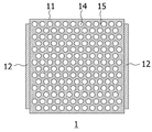
- FIG. 1 is a schematic plan view showing a fluid inflow end surface of a honeycomb structure that constitutes a reducing agent injection device according to Embodiment 1 of the present invention.
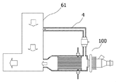
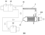
- FIG. 3 is a schematic cross-sectional view for explaining a state in which the reducing agent injection device according to the first embodiment of the present invention is provided in an exhaust stack.
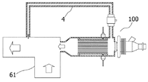
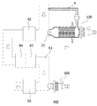
- FIG. 6 is a schematic cross-sectional view for explaining another state in which the reducing agent injection device according to the first embodiment of the present invention is provided in the exhaust stack.
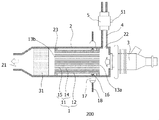
- It is a schematic cross section which shows the reducing agent injection device which concerns on Embodiment 2 of this invention.
- It is a schematic cross section which shows the exhaust gas processing apparatus which concerns on Embodiment 3 of this invention.
- It is a schematic cross section which shows another exhaust gas processing apparatus which concerns on Embodiment 4 of this invention.
- Reducing agent injection device Fig. 1 is a schematic cross-sectional view (a schematic cross-sectional view parallel to the cell extending direction of the honeycomb structure portion) showing the reducing agent injection device according to the first embodiment of the present invention.
- the reducing agent injection device 100 of the present embodiment includes a honeycomb structure 1, an outer cylinder 2, a urea atomizer 3, a carrier gas introduction cylinder 4, and a carrier gas flow rate amplifier 5.
- the honeycomb structure 1 has a columnar honeycomb structure portion 11 having partition walls 15 that partition and form a plurality of cells 14 extending from the fluid inflow end surface 13a to the fluid outflow end surface 13b, and is disposed on the side surface of the honeycomb structure portion 11 to form a honeycomb structure. It has at least a pair of electrode parts 12 for electrically heating the part 11.
- the cells 14 in the honeycomb structure portion 11 serve as a fluid passage.
- the “fluid inflow end surface 13a” means an end surface having a fluid inflow port
- the “fluid outflow end surface 13b” means an end surface having a fluid outflow port. ..
- a pair of electrode portions 12 means that, in a cross section orthogonal to a direction in which the cells 14 of the honeycomb structure portion 11 extend, one electrode portion 12 has the other electrode portion 12 having the honeycomb structure portion. It means that it is arranged on the opposite side across the center of 11.
- the electrode portion 12 is formed in a band shape along the direction in which the cell 14 extends. Note that the electrode portions 12 may be a pair, but may be a plurality of pairs from the viewpoint of increasing the heat generation efficiency of the honeycomb structure portion 11.
- the outer cylinder 2 has an inlet side end and an outlet side end, and houses the honeycomb structure 1 inside.
- the urea sprayer 3 is arranged at one end on the inlet side, and the injection port 21 for injecting ammonia is formed at the other end on the outlet side.
- the outer cylinder 2 has a carrier gas introduction port 22 for introducing a carrier gas between the fluid inflow end surface 13 a of the honeycomb structure portion 11, that is, between the honeycomb structure 1 and the urea sprayer 3.
- the honeycomb structure 1 housed in the outer cylinder 2 is fixed (held) in the outer cylinder 2 via an insulating holding portion 23. This ensures the insulation between the honeycomb structure 1 and the outer cylinder 2.
- the insulating holding portion 23 is not arranged between the honeycomb structure 1 and the outer cylinder 2, the entire outer periphery of the honeycomb structure 1 is covered with the insulating holding portion 23. May be.
- the material of the insulating holding portion 23 is not particularly limited as long as it has excellent insulating properties, and for example, alumina can be used.
- the urea sprayer 3 is arranged at one end (inlet side end) of the outer cylinder 2 and sprays the urea aqueous solution on the fluid inflow end face 13a side of the honeycomb structure part 11.
- the urea aqueous solution is a raw material of ammonia generated by the reducing agent injection device 100 of the present embodiment.
- the carrier gas introducing cylinder 4 is provided at the carrier gas introducing port 22 of the outer cylinder 2.
- the other end of the carrier gas introducing cylinder 4 is connected to a supply source of the carrier gas introduced into the carrier gas introducing cylinder 4.
- the carrier gas is not particularly limited, and exhaust gas, intake gas, air from other air supply devices (such as compressors mounted on large vehicles) can be used, but exhaust gas is preferable. Since the exhaust gas has a high temperature, it can be used as a carrier gas without heating.
- the intake gas gas from the engine intake system
- the intake gas since the intake gas has a low temperature, it is preferable to preheat it by using a heating means or the like.
- the carrier gas flow rate amplifier 5 has a function of amplifying the flow rate of the carrier gas, and is provided in the carrier gas introduction cylinder 4.
- the urea aqueous solution sprayed from the urea sprayer 3 decomposes urea in the urea aqueous solution in the honeycomb structure 11 that is electrically heated to generate ammonia ( A reducing agent) is generated, and ammonia is injected from the injection port 21 to the outside.
- a reducing agent A reducing agent
- ammonia is injected from the injection port 21 to the outside.
- the carrier gas flow amplifier 5 is provided in the carrier gas introduction cylinder 4, the reducing agent injection device 100 is provided.
- the carrier gas can be stably introduced into the inside. Therefore, the heat and the urea aqueous solution are less likely to stagnate in the honeycomb structure portion 11, and the urea deposit can be stably suppressed.
- the honeycomb structure 1 has a honeycomb structure portion 11 and an electrode portion 12.
- the material of the partition walls 15 forming the honeycomb structure portion 11 is not particularly limited, but is preferably ceramics.
- the material of the partition walls 15 is preferably a silicon-silicon carbide composite material or silicon carbide as a main component, and more preferably a silicon-silicon carbide composite material as a main component. By using such a material, it becomes easy to adjust the electric resistivity of the honeycomb structure portion 11 to an arbitrary value by changing the ratio of silicon carbide and silicon.
- the above-mentioned "silicon-silicon carbide composite material” as the main component means a material containing silicon carbide particles as an aggregate and metallic silicon as a binder for bonding the silicon carbide particles.
- silicon-silicon carbide composite material it is preferable that a plurality of silicon carbide particles be bonded by metallic silicon.
- the above-mentioned "silicon carbide” as the main component means one formed by sintering silicon carbide particles.
- a “main component” means a component contained by 90 mass% or more.
- the electrical resistivity of the honeycomb structure part 11 is not particularly limited, but is preferably 0.01 to 500 ⁇ cm, and more preferably 0.1 to 200 ⁇ cm. By controlling to such an electric resistivity, it is possible to effectively heat the honeycomb structure portion 11 by applying a voltage to at least the pair of electrode portions 12. In particular, in order to heat the honeycomb structure part 11 to 160 to 600° C. by using a power source having a voltage of 12 to 200 V, it is preferable to set the electric resistivity within the above range.
- the electric resistivity of the honeycomb structure portion 11 is a value at 25°C.
- the electrical resistivity of the honeycomb structure portion 11 is a value measured by the four-terminal method.
- the surface area per unit volume of the honeycomb structure part 11 is not particularly limited, but is preferably 5 cm 2 /cm 3 or more, more preferably 8 to 45 cm 2 /cm 3 , and more preferably 20 to 40 cm 2 /cm 3. Is particularly preferable.
- the surface area is 5 cm 2 /cm 3 or more, the contact area with the urea aqueous solution is sufficiently secured, and the treatment rate of the urea aqueous solution, that is, the amount of ammonia generated (rate of generation) is appropriately controlled.
- the surface area of the honeycomb structure portion 11 is the surface area of the partition walls 15 of the honeycomb structure portion 11.
- the thickness of the partition walls 15 of the honeycomb structure portion 11 is preferably 0.06 to 1.5 mm, more preferably 0.10 to 0.80 mm.
- the thickness of the partition wall 15 is 1.5 mm or less, the pressure loss is reduced, and the treatment rate of the urea aqueous solution, that is, the amount of ammonia generated (generation rate) is appropriately controlled.
- the partition wall 15 has a thickness of 0.06 mm or more, it is possible to prevent the honeycomb structure portion 11 from being broken by a thermal shock caused by electric heating.
- the shape of the cells 14 (the shape of the cross section orthogonal to the extending direction of the cells 14) is circular as shown in FIG. 2, the thickness of the partition walls 15 is “the distance between the cells 14 is shortest.
- the thickness of the partition wall 15 in the "portion (portion where the partition wall 15 has a small thickness)" is preferably 7 to 140 cells/cm 2, and more preferably 15 to 120 cells/cm 2 .
- the density of the cells 14 is 7 cells/cm 2 or more, the contact area with the urea aqueous solution is sufficiently secured, and the processing rate of the urea aqueous solution, that is, the amount of ammonia generated (generation rate) is appropriately controlled.
- the density of the cells 14 is 140 cells/cm 2 or less, the pressure loss is reduced, and the treatment rate of the urea aqueous solution, that is, the amount of ammonia generated (rate of generation) is appropriately controlled.
- the honeycomb structure portion 11 may be provided with a plugging portion at an end portion on the fluid inflow end face 13a side for some cells 14.
- the material of the plugging portion is preferably the same as the material of the partition wall 15, but may be another material.
- the shape of the fluid inflow end surface 13a may be various shapes such as a rectangle, another polygon, a circle, an ellipse, etc. other than the square as shown in FIG. Further, the shape of the fluid inflow end surface 13a is the same as the shape of the fluid outflow end surface 13b, and preferably the same as the shape of the cross section orthogonal to the extending direction of the cells 14.
- Size of the honeycomb structure portion 11 is preferably an area of the fluid inlet end 13a and a fluid outflow end surface 13b are each 50 ⁇ 10000 mm 2, more preferably 100 ⁇ 8000mm 2.
- the shape of the cell 14 in the cross section orthogonal to the extending direction of the cell 14 is preferably a circle as shown in FIG. 2, an ellipse, a quadrangle, a hexagon, an octagon, or a combination thereof. With such a shape, the pressure loss when the exhaust gas flows through the honeycomb structure portion 11 becomes small, and the urea in the urea aqueous solution can be efficiently decomposed.
- the electrode portion 12 is formed in a strip shape along the direction in which the cells 14 extend, but may be formed in a wide width that also extends in the circumferential direction of the honeycomb structure portion 11. Further, in the cross section orthogonal to the extending direction of the cells 14, one electrode portion 12 is arranged on the opposite side of the other electrode portion 12 with the center of the honeycomb structure portion 11 interposed therebetween. With such a configuration, when a voltage is applied between the pair of electrode portions 12, it is possible to suppress the bias of the current flowing through the honeycomb structure portion 11, and therefore the bias of the heat generation inside the honeycomb structure portion 11. Can be suppressed.
- the voltage is applied to the electrode portion 12 so that the honeycomb structure portion 11 generates heat so that the temperature at the fluid inflow end surface 13a becomes 900° C. or less.
- the temperature of the honeycomb structure portion 11 can be controlled by directly providing the temperature measuring means in the honeycomb structure portion 11.
- the temperature of the honeycomb structure 11 can be estimated and controlled from the carrier gas temperature, the carrier gas flow rate, and the urea solution spray amount. Further, if the engine operating conditions are mapped, the measurement of the carrier gas temperature and the carrier gas flow rate can be replaced.
- the material of the electrode portion 12 is not particularly limited, but is preferably the same as the main component of the partition wall 15 of the honeycomb structure portion 11.
- the electrical resistivity of the electrode portion 12 is preferably 0.0001 to 100 ⁇ cm, and more preferably 0.001 to 50 ⁇ cm. By setting the electric resistivity of the electrode portions 12 in such a range, the pair of electrode portions 12 effectively play the role of electrodes in the exhaust stack in which the high-temperature exhaust gas flows.
- the electrical resistivity of the electrode portion 12 is preferably lower than that of the honeycomb structure portion 11.
- the electric resistivity of the electrode portion 12 is a value at 400°C.
- the electrical resistivity of the electrode part 12 is a value measured by the four-terminal method.
- the pair of electrode portions 12 may be provided with electrode terminal protrusions 16 for connecting the electric wiring 18 from the outside.
- the material of the electrode terminal projecting portion 16 may be conductive ceramics or metal.
- the material of the electrode terminal projecting portion 16 is preferably the same as that of the electrode portion 12. Further, it is preferable that the electrode terminal projecting portion 16 and the connector 17 of the outer cylinder 2 are connected by an electric wiring 18.
- the honeycomb structure part 11 may be equipped with a urea hydrolysis catalyst.
- Ammonia can be efficiently generated from urea by using the urea hydrolysis catalyst.
- the urea hydrolysis catalyst include titanium oxide and the like.
- the material of the outer cylinder 2 is not particularly limited, but stainless steel or the like is preferable.
- the shape of the outer cylinder 2 is preferably the same as the shape of the honeycomb structure portion 11 in a cross section orthogonal to the extending direction of the cells 14 in order to fit the honeycomb structure 1.
- the “similar shape” means that when the outer cylinder 2 has a square shape, the honeycomb structure portion 11 also has a square shape, and when the outer cylinder 2 has a rectangular shape, the honeycomb structure has a honeycomb structure. It means that the shape of the part 11 is also rectangular.
- the shape of the outer cylinder 2 and the shape of the honeycomb structure part 11 are the same kind of shape and the shape is a rectangle, it is not necessary that the ratio of the length to the length is the same.
- the type of the urea sprayer 3 is not particularly limited as long as the urea aqueous solution can be sprayed, but is preferably a solenoid type, an ultrasonic type, a piezoelectric actuator type, or an atomizer type. By using these, the urea aqueous solution can be easily atomized. In addition, among these, when a solenoid type, an ultrasonic type, or a piezoelectric actuator type is used, the urea aqueous solution can be atomized without using air. Therefore, it is not necessary to heat the air used for spraying the urea aqueous solution, and the amount of heating energy can be reduced.
- the size (diameter) of the droplets of the urea aqueous solution sprayed from the urea sprayer 3 is preferably 0.3 mm or less. If the size of the droplet is larger than 0.3 mm, it may be difficult to vaporize when heated in the honeycomb structure portion 11.
- the solenoid-type urea sprayer 3 is a device that sprays the urea aqueous solution into a mist by the back and forth movement of the piston due to the vibration of the solenoid or the electric field using the solenoid.
- the ultrasonic urea sprayer 3 is a device that sprays the urea aqueous solution into a mist by ultrasonic vibration.
- the piezoelectric actuator type urea sprayer 3 is a device that sprays the urea aqueous solution in a mist state by the vibration of the piezoelectric element.
- the atomizer-type urea sprayer 3 is, for example, a device that sucks up a liquid by a pipe and blows the liquid sucked up into the opening portion at the tip of the pipe into a mist by air to spray the liquid.
- the atomizer-type urea sprayer 3 may be a device in which a plurality of small openings are formed at the tip of the nozzle and the liquid is sprayed in a mist form from the openings.
- the urea sprayer 3 has a urea aqueous solution spraying direction (direction in which droplets are ejected) on the fluid inflow end surface 13a side of the honeycomb structure portion 11. Is preferred.
- Carrier gas introducing cylinder 4 The material of the carrier gas introducing cylinder 4 is not particularly limited, but stainless steel or the like is preferable.
- the shape of the carrier gas introduction tube 4 is not particularly limited, but the cross-sectional shape is preferably the same as the shape of the carrier gas introduction port 22 formed in the outer tube 2. With such a shape, it becomes easy to connect the carrier gas introduction cylinder 4 to the carrier gas introduction port 22.
- the carrier gas introduction tube 4 is preferably branched from the exhaust tube 61 through which the exhaust gas flows. With such a configuration, part of the exhaust gas flowing through the exhaust pipe 61 can be easily introduced into the carrier gas introduction pipe 4.
- the carrier gas introducing cylinder 4 be branched from the exhaust cylinder 61 downstream of the position where the ammonia generated by the reducing agent injection device 100 is injected.
- the carrier gas heated in the reducing agent injection device 100 can be reintroduced into the reducing agent injection device 100, so that the effect of suppressing the urea deposit is enhanced.
- ammonia may be contained in the carrier gas. Since it passes through the device 100 as it is, it does not affect the function of the reducing agent injection device 100.
- Carrier gas flow amplifier 5 is not particularly limited, and various flow rate amplifiers such as a Coanda flow rate amplifier utilizing the Coanda effect and an ejector can be used. Such a flow amplifier is commercially available, and for example, an air saver manufactured by Higashihama Kogyo Co., Ltd., an AIR-X manufactured by INOX Toei Co., Ltd., a trans vector and a float trans vector manufactured by Nijieda Co., Ltd. may be used. it can.
- the Coanda flow rate amplifier can amplify the flow rate of the carrier gas to 20 times or more that of the external air by introducing the external air from the external air introduction port 51, for example.
- the carrier gas flow rate amplifier 5 When the exhaust gas is used as the carrier gas, the carrier gas flow rate amplifier 5 preferably amplifies the exhaust gas flowing into the carrier gas introduction tube 4 from the exhaust tube to a flow rate of 1.1 times or more. Moreover, the upper limit of the amplification factor of the flow rate is not particularly limited, but is preferably 1.8 times, more preferably 1.6 times. By amplifying to such a flow rate, the carrier gas can be sufficiently introduced into the reducing agent injection device 100.
- the method for manufacturing the honeycomb structure 1 includes a honeycomb molded body manufacturing step, a honeycomb dried body manufacturing step, a honeycomb body with unfired electrodes manufacturing step, and a honeycomb structure manufacturing step.
- a forming material is extruded to produce a honeycomb formed body.
- the forming raw material preferably contains a ceramic raw material and an organic binder.
- the forming raw material may further contain a surfactant, a sintering aid, a pore-forming material, water and the like.
- the forming raw material can be obtained by mixing these raw materials.
- the ceramic raw material in the forming raw material is "ceramic” or “raw material which becomes ceramic by firing”. In any case, the ceramic raw material becomes a ceramic after firing.
- the ceramic raw material in the forming raw material preferably contains metal silicon and silicon carbide particles (silicon carbide powder) as main components or silicon carbide particles (silicon carbide powder) as main components. Thereby, the obtained honeycomb structure 1 becomes conductive.
- the metal silicon is also preferably metal silicon particles (metal silicon powder).
- “the main component is metallic silicon and silicon carbide particles” means that the total mass of metallic silicon and silicon carbide particles is 90% by mass or more of the whole (ceramic raw material).
- examples of components other than the main component contained in the ceramic raw material include SiO 2 , SrCO 3 , Al 2 O 3 , MgCO 3 , and cordierite.
- silicon carbide is used as the main component of the ceramic raw material
- silicon carbide is sintered by firing.
- metal silicon and silicon carbide particles are used as the main components of the ceramic raw material, the silicon carbide, which is an aggregate, is bonded by firing with the metal silicon as a binder.
- the mass of the metal silicon particles is larger than the sum of the mass of the silicon carbide particles and the mass of the metal silicon particles. It is preferably 10 to 40% by mass.
- the average particle diameter of the silicon carbide particles is preferably 10 to 50 ⁇ m, more preferably 15 to 35 ⁇ m.
- the average particle diameter of the metal silicon particles is preferably 0.1 to 20 ⁇ m, more preferably 1 to 10 ⁇ m.
- the average particle diameters of the silicon carbide particles and the metal silicon particles are values measured by a laser diffraction method.
- organic binder examples include methyl cellulose, glycerin, hydroxypropyl methyl cellulose and the like.
- the organic binder one kind of organic binder may be used, or plural kinds of organic binders may be used.
- the compounding amount of the organic binder is preferably 5 to 10 parts by mass when the total mass of the ceramic raw materials is 100 parts by mass.
- ethylene glycol, dextrin, etc. can be used.
- the surfactant one kind of surfactant may be used, or plural kinds of surfactants may be used.
- the blending amount of the surfactant is preferably 0.1 to 2.0 parts by mass when the total mass of the ceramic raw materials is 100 parts by mass.
- the sintering aid SiO 2 , SrCO 3 , Al 2 O 3 , MgCO 3 , cordierite or the like can be used.
- the sintering aid one kind of sintering aid may be used, or plural kinds of sintering aids may be used.
- the mixing amount of the sintering aid is preferably 0.1 to 3 parts by mass when the total mass of the ceramic raw materials is 100 parts by mass.
- the pore-forming material is not particularly limited as long as it forms pores after firing, and examples thereof include graphite, starch, foamed resin, water-absorbent resin and silica gel.
- the pore former one kind of pore former may be used, or plural kinds of pore formers may be used.
- the compounding amount of the pore former is preferably 0.5 to 10 parts by mass when the total mass of the ceramic raw materials is 100 parts by mass.
- the amount of water is preferably 20 to 60 parts by mass when the total mass of the ceramic raw materials is 100 parts by mass.
- the forming raw material When extrusion molding the forming raw material, first, the forming raw material is kneaded to form a kneaded clay. Next, the kneaded material is extruded to obtain a honeycomb formed body.
- the honeycomb formed body has porous partition walls 15 that partition and form a plurality of cells 14 extending from the fluid inflow end surface 13a to the fluid outflow end surface 13b.
- the partition walls 15 of the honeycomb formed body are undried and unfired partition walls 15.
- the obtained honeycomb molded body is dried to manufacture a honeycomb dried body. Drying conditions are not particularly limited, and known conditions can be used. For example, it is preferably dried at 80 to 120° C. for 0.5 to 5 hours.
- a wide rectangular unfired electrode is formed on the dried honeycomb body so as to extend in a band shape in the extending direction of the cells 14 and also spread in the circumferential direction.
- the circumferential direction is a direction along the side surface of the dried honeycomb body in a cross section orthogonal to the extending direction of the cells 14.
- the electrode forming slurry used in the step of producing the honeycomb body with the unfired electrodes contains the ceramic raw material and water.
- the electrode forming slurry may be mixed with a surfactant, a pore former, water and the like.
- the ceramic raw material it is preferable to use the ceramic raw material used when manufacturing the honeycomb formed body.
- the main components of the ceramic raw material used when manufacturing the honeycomb formed body are silicon carbide particles and metallic silicon
- silicon carbide particles and metallic silicon may be used also as the ceramic raw material of the electrode forming slurry.
- the method of applying the electrode forming slurry to the side surface of the dried honeycomb body is not particularly limited.
- the electrode forming slurry can be applied using a brush or a printing method, for example.
- the viscosity of the electrode forming slurry at 20° C. is preferably 500 Pa ⁇ s or less, more preferably 10 to 200 Pa ⁇ s. When the viscosity of the electrode forming slurry is 500 Pa ⁇ s or less, it becomes easy to apply the electrode forming slurry to the side surface of the honeycomb dried body.
- the electrode forming slurry After applying the electrode forming slurry to the dried honeycomb body, the electrode forming slurry can be dried to obtain an unfired electrode (honeycomb body with unfired electrodes).
- the drying temperature is preferably 80 to 120°C.
- the drying time is preferably 0.1 to 5 hours.
- the honeycomb structure with an unfired electrode is fired to manufacture the honeycomb structure 1.
- the firing conditions may be appropriately determined depending on the types of the ceramic raw material used for manufacturing the honeycomb formed body and the ceramic raw material used for the electrode forming slurry. Further, it is preferable to perform calcination after drying the honeycomb molded body with an unfired electrode and before removing the binder to remove the binder and the like. The calcination is preferably performed at 400 to 500° C. for 0.5 to 20 hours in the air atmosphere.
- the honeycomb structure 1 When supporting the urea hydrolysis catalyst 40 on the honeycomb structure 1, as a method thereof, for example, the honeycomb structure 1 may be immersed in a container in which the slurry of the urea hydrolysis catalyst 40 is stored.
- the catalyst By adjusting the viscosity of the slurry of the urea hydrolysis catalyst 40 and the particle size of the urea hydrolysis catalyst 40 contained therein, the catalyst is supported not only on the surface of the partition wall 15 but also inside the pores of the partition wall 15.
- the amount of the catalyst to be supported can be adjusted. Further, the amount of the catalyst to be carried can be adjusted by sucking the slurry a plurality of times.
- the honeycomb structure 1 is inserted into the outer cylinder 2, and the honeycomb structure 1 is fixed in the outer cylinder 2 via the insulating holding portion 23.
- the urea sprayer 3 is arranged at one end (end on the inlet side).
- the connector 17 of the outer cylinder 2 and the electrode terminal projecting portions 16 arranged on the pair of electrode portions 12 are connected by the electric wiring 18.
- the reducing agent injection device 100 can be manufactured by connecting the carrier gas introduction tube 4 to the carrier gas introduction port 22 of the outer cylinder 2 and providing the carrier gas flow rate amplifier 5 in the carrier gas introduction tube 4.
- the reducing agent injecting device 100 of the present embodiment supplies urea aqueous solution as a raw material to decompose urea in the urea aqueous solution to generate ammonia, and generate the generated ammonia. Inject outside. Specifically, the honeycomb structure 11 is energized to raise the temperature (heat), the urea aqueous solution is supplied to the urea sprayer 3, and the urea aqueous solution is sprayed from the urea sprayer 3 to the fluid inflow end surface 13a side of the honeycomb structure 11. ..
- the carrier gas whose flow rate has been amplified by the carrier gas flow rate amplifier 5 is introduced from the carrier gas introduction port 22 to the fluid inflow end surface 13a side of the honeycomb structure portion 11 to promote the flow of the urea aqueous solution and thereby the honeycomb structure portion.
- the urea aqueous solution is less likely to stagnate in 11.
- the urea aqueous solution sprayed from the urea sprayer 3 is heated in the honeycomb structure 11 and evaporated.
- the urea aqueous solution enters the cells 14 of the honeycomb structure section 11 from the fluid inflow end surface 13a due to the pressure increase in the region between the honeycomb structure section 11 and the urea sprayer 3 due to the evaporation of the urea aqueous solution and the flow of the carrier gas.
- Urea in the urea aqueous solution supplied into the cells 14 is decomposed by the temperature of the heated honeycomb structure 11 to generate ammonia.
- the flow rate of the carrier gas after being amplified by the carrier gas flow rate amplifier 5 is not particularly limited, but is preferably 1 to 200 L/min, more preferably 2 to 50 L/min. With such a flow rate, the carrier gas can be efficiently introduced into the honeycomb structure portion 11.
- the supply amount of the urea aqueous solution is not particularly limited, but is preferably 1.0 to 2.0 in an equivalent ratio with respect to the amount of nitrogen oxides (NOx) contained in the exhaust gas. If the equivalent ratio is less than 1.0, the amount of nitrogen oxides discharged without being purified may increase. However, the equivalence ratio may be less than 1.0 if the SCR catalyst is provided with the NOx storage function. If the equivalence ratio exceeds 2.0, there is a possibility that the exhaust gas may be discharged with ammonia mixed in the exhaust gas.
- the aqueous urea solution is not particularly limited, but an aqueous solution containing 10 to 40 mass% urea is preferable.
- an aqueous solution containing 10 to 40 mass% urea is preferable.
- the urea content is less than 10% by mass, a large amount of urea aqueous solution needs to be sprayed for NOx reduction, and the amount of electric power required for the electric heating of the honeycomb structure part 11 may increase. If the urea content exceeds 40% by mass, there is a concern that urea will solidify in cold regions.
- AdBlue 32.5 mass% urea aqueous solution, a registered trademark of German Automobile Manufacturers Association (VDA)
- the heating temperature of the honeycomb structure portion 11 is preferably 160° C. or higher, more preferably 160 to 600° C., and further preferably 250 to 400° C. When the heating temperature is 160° C. or higher, urea is likely to be efficiently decomposed. When the heating temperature is 600° C. or lower, ammonia is burned, and it is suppressed that ammonia is not supplied to the exhaust stack 61. In addition, it is preferable that the heating temperature of the honeycomb structure portion 11 is 360° C. or higher, because sulfur compounds such as ammonium hydrogensulfate and ammonium sulfate deposited on the reducing agent injection device 100 can be removed.
- the maximum voltage applied to the honeycomb structure portion 11 is preferably 12 to 200V, more preferably 12 to 100V, and further preferably 12 to 48V.
- the maximum voltage is 12 V or higher, it becomes easy to raise the temperature of the honeycomb structure portion 11.
- the maximum voltage is 200 V or less, it is possible to prevent the device for boosting the voltage from becoming expensive.
- FIG. 5 is a schematic cross-sectional view (a schematic cross-sectional view parallel to the cell extending direction of the honeycomb structure portion) showing the reducing agent injection device according to Embodiment 2 of the present invention.
- the reducing agent injection device 200 of the present embodiment is different from the reducing agent injection device 100 of the first embodiment in that the honeycomb structure portion 11 has a space on the fluid outflow end surface 13b side with the fluid outflow end surface 13b.
- the configuration is different in that it further includes a urea hydrolysis catalyst body 31 that is arranged apart. Note that other configurations of the reducing agent injection device 200 of the present embodiment are the same as those of the reducing agent injection device 100 of the first embodiment, and therefore a description thereof will be omitted and only different points will be described in detail.
- the urea hydrolysis catalyst body 31 is provided on the fluid outflow end surface 13b side of the honeycomb structure portion 11 with a space from the fluid outflow end surface 13b. With such a configuration, unreacted urea in the honeycomb structure portion 11 can be decomposed into ammonia by the urea hydrolysis catalyst body 31, so that the ammonia generation efficiency is improved.
- the urea hydrolysis catalyst body 31 is preferably a honeycomb structure carrying a urea hydrolysis catalyst.
- the carrier (honeycomb structure) used for the urea hydrolysis catalyst body 31 may have the same structure and material as the honeycomb structure 1 provided upstream. Although the honeycomb structure used for the urea hydrolysis catalyst body 31 does not have to have the pair of electrode portions 12, it may be configured to be capable of being electrically heated like the honeycomb structure 1 provided upstream. ..
- the urea hydrolysis catalyst body 31 may be produced by manufacturing a honeycomb structure (carrier) in the same manner as the honeycomb structure 1 provided upstream, and then supporting the urea hydrolysis catalyst on the honeycomb structure.
- the method for supporting the urea hydrolysis catalyst on the honeycomb structure is as described above.
- the exhaust gas treatment devices 300 and 400 of the present embodiment include an exhaust pipe 61 through which exhaust gas flows, a reducing agent injection device 100 for injecting ammonia into the exhaust pipe 61, An SCR catalyst 62 arranged downstream of the position where the ammonia is injected in the exhaust stack 61 is provided.
- the exhaust stack 61 is a pipe through which exhaust gas (exhaust gas containing NOx) exhausted from various engines is passed, in which exhaust gas and ammonia are mixed.
- the size of the exhaust stack 61 is not particularly limited, and can be appropriately determined according to the exhaust system of the engine or the like to which the exhaust gas treatment device 300 or 400 of the present embodiment is attached.
- the length of the exhaust stack 61 in the gas flow direction is not particularly limited, but the length between the reducing agent injection device 100 and the SCR catalyst 62 can be set to an appropriate distance. Is preferred.
- the material of the exhaust pipe 61 is not particularly limited, but it is preferable that the exhaust pipe 61 is less likely to be corroded by the exhaust gas.
- Examples of the material of the exhaust tube 61 include stainless steel.
- the carrier gas introduction tube 4 When exhaust gas is used as the carrier gas to be introduced into the reducing agent injection device 100, the carrier gas introduction tube 4 is connected so as to branch from the exhaust tube 61, as shown in FIGS. 6 and 7.
- the position of the carrier gas introduction cylinder 4 branched from the exhaust cylinder 61 may be upstream of the reducing agent injection device 100, but may be downstream of the reducing agent injection device 100.
- the carrier gas introducing cylinder 4 downstream of the reducing agent injection device 100, the carrier gas heated in the reducing agent injection device 100 can be reintroduced into the reducing agent injection device 100, thus suppressing urea deposit. The effect of doing is higher.
- a carrier gas other than exhaust gas for example, intake gas
- the carrier gas introduction cylinder 4 is connected to the carrier gas supply source.
- the injection port 21 is attached to the exhaust pipe 61, and the ammonia is injected into the exhaust pipe 61.
- the ammonia is injected into the exhaust pipe 61.
- a mixed gas of ammonia and exhaust gas is generated in the exhaust stack 61.
- One reducing agent injection device 100 may be attached to the exhaust stack 61 as shown in FIG. Further, as shown in FIG. 7, two reducing agent injection devices may be attached to the exhaust stack 61.
- a conventional reducing agent injection device 500 for example, the urea atomizer 3 that sprays the reducing agent (urea water) without heating. It may be.
- the reducing spray device on the downstream side is a conventional reducing agent injection device 500 that sprays the reducing agent (urea water) without heating.
- a conventional reducing agent injection device 500 that sprays the reducing agent (urea water) without heating.
- the amount of NOx in the exhaust gas is small (when the temperature of the exhaust gas is low)
- most of the NOx is purified by the reducing agent injection device 100 and the SCR catalyst 62 on the upstream side, and the amount of NOx in the exhaust gas is reduced.
- the urea water sprayed from the conventional reducing agent injection device 500 is decomposed into ammonia by the temperature of the exhaust gas.
- three or more reducing agent injection devices 100 may be attached to the exhaust stack 61 as needed.
- the SCR catalyst 62 is arranged downstream of the position where the ammonia is injected in the exhaust stack 61 in the state of the catalyst body (honeycomb structure carrying the SCR catalyst 62). Therefore, as shown in FIG. 6, when one reducing agent injection device 100 is attached to the exhaust pipe 61, the SCR catalyst 62 is provided in the exhaust pipe 61 on the downstream side of the position where the reducing agent injection device 100 is attached. Will be placed. Further, as shown in FIG. 7, when two reducing agent injection devices 100 are attached to the exhaust stack 61, exhaust gas on the downstream side of the position where the reducing agent injection device 100 and the conventional reducing agent injection device 500 are attached. The SCR catalyst 62 is arranged in each cylinder 61.
- Examples of the SCR catalyst 62 include a vanadium catalyst and a zeolite catalyst.
- the SCR catalyst 62 is used as a catalyst body supported on a honeycomb structure, it is preferable to store the catalyst body in a container and mount the container on the downstream side of the exhaust pipe 61.
- the honeycomb structure carrying the SCR catalyst 62 is not particularly limited, and those known in the art can be used.
- a filter for collecting the particulate matter in the exhaust gas is preferably arranged on the upstream side of the exhaust stack 61.
- a filter for collecting the particulate matter for example, a honeycomb-shaped ceramic DPF (diesel particulate filter) 63 can be cited.
- an oxidation catalyst 64 for removing hydrocarbons and carbon monoxide in the exhaust gas is preferably arranged on the upstream side of the exhaust stack 61. It is preferable that the oxidation catalyst 64 be in a state of being supported on a ceramic honeycomb structure (oxidation catalyst body).
- a noble metal such as platinum (Pt), palladium (Pd), rhodium (Rh) is preferably used.
- the DPF 63 and the oxidation catalyst 64 are installed in the exhaust stack 61 upstream of the ammonia injection position by the reducing agent injection device 100, as shown in FIG. Will be placed.
- the DPF 63 and the oxidation catalyst 64 are located upstream of the injection position of ammonia by the conventional reducing agent injection device 500, as shown in FIG. 7. It is provided in the exhaust stack 61 on the downstream side of the SCR catalyst 62 located on the downstream side of the position where the reducing agent injection device 100 is mounted.
- an ammonia removal catalyst for removing ammonia on the downstream side of the SCR catalyst 62.
- an ammonia removal catalyst for removing ammonia on the downstream side of the SCR catalyst 62.
- oxidation catalyst a noble metal such as platinum (Pt), palladium (Pd) or rhodium (Rh) is preferably used.
- the exhaust gas treatment method according to the fourth embodiment of the present invention injects the ammonia generated by the reducing agent injection device 100, 200 of the first or second embodiment into the exhaust gas, and reduces the exhaust gas mixed with the ammonia by the SCR catalyst. As a result, NOx in the exhaust gas can be removed.
- This exhaust gas treatment method can be easily implemented by using the exhaust gas treatment devices 300 and 400 of the third embodiment.
- the reducing agent injection devices 100 and 200 stably supply the carrier gas whose flow rate has been amplified by the carrier gas flow rate amplifier 5 to the fluid inflow end face 13a side of the honeycomb structure 11 together with the urea aqueous solution sprayed from the urea sprayer 3. can do.
- the flow of gas in the honeycomb structure portion 11 can be sufficiently promoted and urea can be prevented from remaining in the honeycomb structure portion 11, so that the limit of urea deposit generation can be increased.
- the thermally decomposed ammonia can be discharged to the outside by the carrier gas, so that the responsiveness is improved.
- the temperature and flow rate of the carrier gas and the power supply to the honeycomb structure 1 so that the temperature of the fluid inflow end surface 13a of the honeycomb structure portion 11 becomes 150° C. or higher, preferably 250° C. or higher.
- the temperature of the carrier gas is 180° C. or higher and the flow rate is 10 L/min or higher.
- the power supplied to the honeycomb structure 1 is preferably 150 to 500W.
- the injection amount of ammonia injected from the reducing agent injection devices 100 and 200 is preferably 1.0 to 2.0 in terms of an equivalent ratio with respect to the amount of nitrogen oxides contained in the exhaust gas. If the equivalent ratio is less than 1.0, the amount of nitrogen oxides discharged without being purified may increase. If the equivalence ratio exceeds 2.0, there is a possibility that the exhaust gas may be discharged with ammonia mixed in the exhaust gas.
- the amount of sprayed urea aqueous solution and the temperature (supply power) of the honeycomb structure 11 are preferably controlled by an electronic controller. Further, the temperature may be calculated from the resistance value of the honeycomb structure portion 11 and the temperature of the honeycomb structure portion 11 may be controlled so that the calculated temperature becomes a desired temperature.
- the reducing agent injection device 100 as shown in FIG. 1 was produced according to the following procedure. First, silicon carbide (SiC) powder and metallic silicon (Si) powder were mixed at a mass ratio of 70:30 to prepare a ceramic raw material. Then, hydroxypropylmethylcellulose as a binder and a water-absorbent resin as a pore-forming material were blended with the ceramic raw material, and water was further blended to obtain a molding raw material. Then, the forming raw material was kneaded by a vacuum clay kneader to prepare a kneaded clay.
- SiC silicon carbide
- Si metallic silicon
- the binder content was 7 parts by mass with respect to 100 parts by mass of the ceramic raw material.
- the compounding amount of the pore former was 3 parts by mass with respect to 100 parts by mass of the ceramic raw material.
- the blending amount of water was 42 parts by mass with respect to 100 parts by mass of the ceramic raw material.
- the silicon carbide powder had an average particle diameter of 20 ⁇ m, and the metal silicon powder had an average particle diameter of 6 ⁇ m.
- the average particle size of the pore former was 20 ⁇ m.
- the average particle diameters of silicon carbide, metallic silicon and the pore-forming material are values measured by a laser diffraction method.
- the obtained kneaded material was molded using an extrusion molding machine to obtain a honeycomb molded body having a quadrangular prism shape (columnar section having a square cross section orthogonal to the cell extending direction).
- the obtained honeycomb formed body was subjected to high frequency dielectric heating and drying, and then dried at 120° C. for 2 hours using a hot air dryer, and both end faces were cut by a predetermined amount.
- silicon carbide (SiC) powder and metallic silicon (Si) powder were mixed at a mass ratio of 60:40 to prepare a ceramic raw material for electrode formation.
- hydroxypropylmethyl cellulose as a binder, glycerin as a moisturizer, and a surfactant as a dispersant were mixed with the ceramic raw material for electrode formation, and water was further mixed and mixed. Then, the mixture was kneaded to obtain an electrode forming slurry.
- the electrode forming slurry was applied in a strip shape on two parallel side surfaces of the dried honeycomb formed body (honeycomb dried body).
- the electrode-forming slurry is applied in a strip shape on one side surface of the “side surfaces having four planes (four side surfaces)” of the honeycomb dried body, and is applied in parallel to the “applied side surface”. It was applied in strips on one side.
- the shape (peripheral shape) of the electrode forming slurry applied to the side surface of the dried honeycomb body was rectangular.
- the electrode-forming slurry applied to the dried honeycomb body was dried to obtain a honeycomb body with unfired electrodes.
- the drying condition was 70°C.
- two electrode terminal projecting portions 16 were individually manufactured using the same material as the electrode forming slurry.
- each of the two electrode terminal projecting portions 16 was attached to each of the two electrode portions of the honeycomb body with the unfired electrodes.
- the honeycomb body with an unfired electrode was degreased, fired, and further oxidized to obtain a honeycomb structure 1.
- the degreasing condition was 550° C. for 3 hours.
- the firing conditions were 1450° C. and 2 hours under an argon atmosphere.
- the conditions for the oxidation treatment were 1300° C. for 1 hour.
- the partition walls 15 of the honeycomb structure 1 obtained as described above had a thickness of 0.152 mm and a cell pitch of 1.11 mm.
- the surface area per unit volume of the honeycomb structure 11 was 31.1 cm 2 /cm 3 .
- the honeycomb structure 1 had a columnar shape with a square bottom surface, and one side of the bottom surface was 30 mm.
- the length of the honeycomb structure 1 in the extending direction of the cells 14 was 25 mm.
- the electrical resistivity of the electrode part was 0.1 ⁇ cm, and the electrical resistivity of the honeycomb structure part 11 was 1.4 ⁇ cm. No plugged portion was formed in the honeycomb structure 1.
- the outer cylinder 2 was made of stainless steel.
- One connector 17 for electric wiring was attached to the outer circumference of the outer cylinder 2.
- the honeycomb structure 1 was inserted into the outer cylinder 2 and fixed by the insulating holding portion 23.
- one of the electrode terminal protrusions 16 of the honeycomb structure 1 and the connector 17 of the outer cylinder 2 were connected by the electric wiring 18. Further, the other electrode terminal projecting portion 16 is made to contact the outer cylinder 2.
- a solenoid type urea sprayer 3 is installed in the inlet side end portion of the outer cylinder 2, and a carrier gas introducing cylinder 4 made of stainless steel is connected to the carrier gas introducing mouth 22 of the outer cylinder 2 to connect the carrier gas introducing cylinder 4 Further, an air saver manufactured by Tohama Industry Co., Ltd. was provided as the carrier gas flow rate amplifier 5 to obtain the reducing agent injection device 100.
- Example 1 A reducing agent injection device was obtained in the same manner as in Example 1 except that the carrier gas flow rate amplifier 5 was not provided.
- the reducing agent injection device obtained in the above embodiment is provided at a predetermined position of the exhaust stack shown in FIG. 3, the amplification factor of the flow rate of exhaust gas by the carrier gas flow rate amplifier 5 is changed, and a fixed amount of aqueous urea solution (AdBlue) Was continuously sprayed for 30 minutes to determine the maximum spray amount (g/min) of the urea aqueous solution when urea deposit was not generated on the fluid inflow end surface side of the honeycomb structure part.
- AdBlue aqueous urea solution
- the reducing agent injection device of the embodiment provided with the carrier gas flow rate amplifier 5 is different from the reducing agent injection device of the comparative example not provided with the carrier gas flow rate amplifier 5 in the fluid inflow end surface of the honeycomb structure portion. It was found that the maximum amount of urea aqueous solution sprayed when urea deposits did not occur on the side was large, and urea deposits could be stably suppressed. In particular, when the amplification factor of the flow rate of the exhaust gas by the carrier gas flow rate amplifier 5 is set to 1.10 times or more, the maximum spray amount of the urea aqueous solution becomes larger when urea deposit does not occur on the fluid inflow end face side of the honeycomb structure part. It was
- a reducing agent injection device that can stably suppress urea deposits. Further, according to the present invention, it is possible to provide an exhaust gas treatment device and an exhaust gas treatment method capable of stably injecting a necessary amount of ammonia from the reducing agent injection device to purify NOx.
- the reducing agent injection device, the exhaust gas treatment device and the exhaust gas treatment method of the present invention can be suitably used for purifying NOx in exhaust gas emitted from various engines and the like.
Landscapes
- Chemical & Material Sciences (AREA)
- Engineering & Computer Science (AREA)
- Chemical Kinetics & Catalysis (AREA)
- Combustion & Propulsion (AREA)
- Health & Medical Sciences (AREA)
- Mechanical Engineering (AREA)
- General Engineering & Computer Science (AREA)
- Toxicology (AREA)
- Ceramic Engineering (AREA)
- Biomedical Technology (AREA)
- Environmental & Geological Engineering (AREA)
- Analytical Chemistry (AREA)
- General Chemical & Material Sciences (AREA)
- Oil, Petroleum & Natural Gas (AREA)
- Exhaust Gas Treatment By Means Of Catalyst (AREA)
- Exhaust Gas After Treatment (AREA)
Abstract
Description
特許文献1に記載の排ガス処理装置は、エンジンの排気筒に取り付けられた触媒(SCR触媒)、及びエンジンと触媒との間の排気筒内に尿素水を噴射する手段を有し、噴霧された尿素水を排ガスと混合し、触媒によって排ガス中の特定成分と反応させると共に尿素水を排ガスと混合する尿素水噴射手段が複数個所に設けられている。
しかしながら、特許文献1に記載の排ガス処理装置は、尿素水中の尿素を排ガスの熱でアンモニアに分解させるため、排ガスの温度が200℃以上であることが必要とされる。そのため、排ガスの温度が低いときには、尿素の分解反応が起こり難くなり、NOxの処理に必要なアンモニアの量が不足するという問題があった。
しかしながら、通電加熱されたハニカム構造部に尿素水溶液を噴霧すると、尿素水溶液が噴霧された領域の温度が低下し、ハニカム構造部内に温度ムラが発生する。その結果、ハニカム構造部の低温領域に尿素デポジット(尿素に起因する結晶)が生成し易くなる。尿素デポジットが生成すると、ハニカム構造部内の流路が遮断されるため、尿素からアンモニアへの分解が阻害されてしまう。
また、本発明は、還元剤噴射装置から必要量のアンモニアを安定的に噴射してNOxの浄化を行うことが可能な排ガス処理装置及び排ガス処理方法を提供することを目的とする。
前記ハニカム構造体を収容し、前記ハニカム構造部の前記流体流入端面側にキャリアガスを導入するためのキャリアガス導入口を有する外筒と、
前記外筒の一端に配置され、前記ハニカム構造部の前記流体流入端面側に尿素水溶液を噴霧する尿素噴霧器と、
前記外筒のキャリアガス導入口に設けられたキャリアガス導入筒と、
前記キャリアガス導入筒に設けられ、前記キャリアガスの流量を増幅するためのキャリアガス流量増幅器と
を備える、還元剤噴射装置である。
前記排気筒内にアンモニアを噴射するための、前記還元剤噴射装置と、
前記排気筒の、前記アンモニアが噴射される位置よりも下流側に配置されたSCR触媒と
を備える排ガス処理装置である。
また、本発明によれば、還元剤噴射装置から必要量のアンモニアを安定的に噴射してNOxの浄化を行うことが可能な排ガス処理装置及び排ガス処理方法を提供することができる。
(1)還元剤噴射装置
図1は、本発明の実施形態1に係る還元剤噴射装置を示す模式断面図(ハニカム構造部のセルの延びる方向に平行な模式断面図)である。
図1に示すように、本実施形態の還元剤噴射装置100は、ハニカム構造体1と、外筒2と、尿素噴霧器3と、キャリアガス導入筒4と、キャリアガス流量増幅器5とを備える。
ここで、本明細書において「流体流入端面13a」とは、流体の流入口を有する端面のことを意味し、「流体流出端面13b」とは、流体の流出口を有する端面のことを意味する。また、本明細書において「一対の電極部12」とは、ハニカム構造部11のセル14が延びる方向に直交する断面において、一方の電極部12に対して、他方の電極部12がハニカム構造部11の中心を挟んで反対側に配設されていることを意味する。
電極部12は、セル14が延びる方向に沿って帯状に形成されている。なお、電極部12は一対であってよいが、ハニカム構造部11の発熱効率を高める観点から、複数対としてもよい。
外筒2に収容されるハニカム構造体1は、絶縁保持部23を介して外筒2内に固定(保持)されている。これにより、ハニカム構造体1と外筒2との間の絶縁が確保される。ハニカム構造体1と外筒2との間には、絶縁保持部23が配置されていない部分(空間)があってもよいが、ハニカム構造体1の外周全体が絶縁保持部23で覆われていてもよい。絶縁保持部23の材質は、絶縁性に優れたものであれば特に限定されず、例えば、アルミナを用いることができる。
キャリアガスとしては、特に限定されず、排ガス、吸気ガス、その他のエアー供給装置(大型車両などに搭載されているコンプレッサーなど)からのエアーなどを用いることができるが、排ガスが好ましい。排ガスは温度が高いため、加熱しなくてもキャリアガスとして利用することができる。なお、吸気ガス(エンジン吸気系からのガス)をキャリアガスとして用いる場合、吸気ガスは温度が低いため、加熱手段などを用いて予め加熱することが好ましい。
ハニカム構造体1は、ハニカム構造部11と電極部12とを有する。
ハニカム構造部11を構成する隔壁15の材質は、特に限定されないが、セラミックスであることが好ましい。特に、隔壁15の材質は、珪素-炭化珪素複合材又は炭化珪素を主成分としていることが好ましく、珪素-炭化珪素複合材を主成分としていることがより好ましい。このような材質を用いることにより、ハニカム構造部11の電気抵抗率を、炭化珪素と珪素との比率を変更することで任意の値に調整し易くなる。
ここで、上記の主成分となる「珪素-炭化珪素複合材」とは、骨材としての炭化珪素粒子、及び炭化珪素粒子を結合させる結合材としての金属珪素を含有するものを意味する。珪素-炭化珪素複合材は、複数の炭化珪素粒子が、金属珪素によって結合されていることが好ましい。また、上記の主成分となる「炭化珪素」とは、炭化珪素粒子同士が焼結して形成されたものを意味する。また、本明細書において「主成分」とは、90質量%以上含有される成分のことを意味する。
なお、ハニカム構造部11の電気抵抗率は、25℃における値である。また、ハニカム構造部11の電気抵抗率は、四端子法により測定した値である。
なお、ハニカム構造部11の表面積は、ハニカム構造部11の隔壁15の表面の面積である。
セル14の形状(セル14の延びる方向に直交する断面の形状)が、図2に示すような円形の場合、隔壁15の厚さは、「セル14同士の間の距離が最も短くなっている部分(隔壁15の厚さが小さい部分)」における隔壁15の厚さを意味する。
セル14の密度は、7~140セル/cm2が好ましく、15~120セル/cm2が更に好ましい。セル14の密度が7セル/cm2以上であると、尿素水溶液との接触面積が十分に確保され、尿素水溶液の処理速度、すなわちアンモニアの発生量(発生速度)が適切に制御される。セル14の密度が140セル/cm2以下であると、圧力損失が低減され、尿素水溶液の処理速度、すなわちアンモニアの発生量(発生速度)が適切に制御される。
また、電極部12に対する電圧の印加は、流体流入端面13aにおける温度が900℃以下となるようにハニカム構造部11を発熱させることが好ましい。ハニカム構造部11の温度の制御はハニカム構造部11に温度測定手段を直接設けることにより制御することができる。あるいは、キャリアガス温度、キャリアガス流量及び尿素水溶液噴霧量からハニカム構造部11の温度を推定して制御することも可能である。また、エンジンの運転条件をマッピングすれば、キャリアガス温度及びキャリアガス流量の測定に代えることもできる。
電極部12の電気抵抗率は、0.0001~100Ωcmであることが好ましく、0.001~50Ωcmであることがより好ましい。電極部12の電気抵抗率をこのような範囲にすることにより、一対の電極部12が、高温の排ガスが流れる排気筒内において、電極の役割を効果的に果たす。電極部12の電気抵抗率は、ハニカム構造部11の電気抵抗率より低いものであることが好ましい。
なお、電極部12の電気抵抗率は、400℃における値である。また、電極部12の電気抵抗率は、四端子法により測定した値である。
外筒2の材質は、特に限定されないが、ステンレス鋼などが好ましい。
外筒2の形状は、ハニカム構造体1と嵌合させるため、セル14の延びる方向に直交する断面において、ハニカム構造部11の形状と同種であることが好ましい。ここで、本明細書において「同種の形状」とは、外筒2の形状が正方形であるときには、ハニカム構造部11の形状も正方形であり、外筒2の形状が長方形であるときには、ハニカム構造部11の形状も長方形であることを意味する。なお、例えば、外筒2の形状及びハニカム構造部11の形状が、同種の形状であり、その形状が長方形である場合、縦と横との長さの比までが同じである必要はない。
尿素噴霧器3の種類は、尿素水溶液を噴霧可能であれば特に限定されないが、ソレノイド式、超音波式、圧電アクチュエータ式、又はアトマイザー式であることが好ましい。これらを用いることにより、尿素水溶液を容易に霧状に噴霧することができる。また、これらの中でも、ソレノイド式、超音波式、又は圧電アクチュエータ式を用いると、空気を使用せずに尿素水溶液を霧状に噴霧することができる。そのため、尿素水溶液の噴霧に用いる空気を加熱する必要がなくなり、加熱するエネルギー量を低減することができる。また、噴霧に用いる空気を使用しないことにより、噴射体積が減少するため、ハニカム構造部11内を霧状の尿素水溶液が通過する速度を低下させることが可能となり、分解に必要な反応時間を長く取ることができる。尿素噴霧器3から噴霧される尿素水溶液の液滴の大きさ(直径)は、0.3mm以下であることが好ましい。液滴の大きさが0.3mmより大きいと、ハニカム構造部11内で加熱された際に、気化し難くなることがある。
キャリアガス導入筒4の材質は、特に限定されないが、ステンレス鋼などが好ましい。
キャリアガス導入筒4の形状は、特に限定されないが、断面形状が、外筒2に形成されたキャリアガス導入口22の形状と同種であることが好ましい。このような形状であれば、キャリアガス導入口22にキャリアガス導入筒4を接続することが容易になる。
キャリアガス流量増幅器5としては、特に限定されず、コアンダ効果を利用したコアンダ流量増幅器、エジェクタなどの様々な流量増幅器を用いることができる。このような流量増幅器は市販されており、例えば、東浜工業株式会社製のエアー・セーバー、INOX東栄株式会社製のAIR-X、虹枝株式会社製のトランスベクター及びフロートトランスベクターなどを用いることができる。コアンダ流量増幅器は、例えば、外部エアー導入口51から外部エアーを導入することにより、外部エアーの20倍以上にキャリアガスの流量を増幅させることができる。
(2)還元剤噴射装置100の製造方法
(2-1)ハニカム構造体1の製造
ハニカム構造体1がセラミックス製の場合、ハニカム構造体1の製造方法は、以下のような製造方法であることが好ましい。
ハニカム構造体1の製造方法は、ハニカム成形体作製工程と、ハニカム乾燥体作製工程と、未焼成電極付きハニカム体作製工程と、ハニカム構造体作製工程とを含む。
ハニカム成形体作製工程では、成形原料を押出成形してハニカム成形体を作製する。成形原料は、セラミックス原料及び有機バインダを含むことが好ましい。成形原料には、セラミックス原料及び有機バインダ以外に、界面活性剤、焼結助剤、造孔材、水などをさらに配合してもよい。成形原料は、これらの原料を混合することによって得ることができる。
ハニカム乾燥体作製工程では、得られたハニカム成形体を乾燥させてハニカム乾燥体を作製する。乾燥条件は、特に限定されず、公知の条件を用いることができる。例えば、80~120℃で、0.5~5時間乾燥させることが好ましい。
未焼成電極付きハニカム体作製工程では、まず、ハニカム乾燥体の側面に、セラミックス原料と水とを含有する電極形成用スラリーを塗布する。次に、電極形成用スラリーを乾燥させて未焼成電極を形成して、未焼成電極付きハニカム体を作製する。
セラミックス原料としては、ハニカム成形体を作製する際に用いられるセラミックス原料を用いることが好ましい。例えば、ハニカム成形体を作製する際に用いられるセラミックス原料の主成分を炭化珪素粒子及び金属珪素とした場合には、電極形成用スラリーのセラミックス原料としても炭化珪素粒子及び金属珪素を用いればよい。
ハニカム構造体作製工程では、未焼成電極付きハニカム体を焼成してハニカム構造体1を作製する。
焼成条件は、ハニカム成形体の製造に用いられたセラミックス原料、及び電極形成用スラリーに用いられたセラミックス原料の種類に応じて適宜決定すればよい。
また、未焼成電極付きハニカム成形体を乾燥させた後、焼成前に、バインダなどを除去するため、仮焼成を行うことが好ましい。仮焼成は、大気雰囲気下、400~500℃で0.5~20時間行うことが好ましい。
外筒2内にハニカム構造体1を挿入し、絶縁保持部23を介してハニカム構造体1を外筒2内に固定すると共に、外筒2の一端(入口側端部)に尿素噴霧器3を配置する。そして、外筒2のコネクター17と一対の電極部12に配設した電極端子突起部16との間を電気配線18によって接続する。また、外筒2のキャリアガス導入口22にキャリアガス導入筒4を接続し、キャリアガス導入筒4にキャリアガス流量増幅器5を設けることにより、還元剤噴射装置100を製造することができる。
(3)還元剤噴射装置100の使用方法
本実施形態の還元剤噴射装置100は、尿素水溶液を原料として供給することにより、尿素水溶液中の尿素を分解してアンモニアを生成させ、生成したアンモニアを外部に噴射する。具体的には、ハニカム構造部11を通電して昇温(加熱)し、尿素噴霧器3に尿素水溶液を供給し、尿素噴霧器3からハニカム構造部11の流体流入端面13a側に尿素水溶液を噴霧する。このとき、キャリアガス流量増幅器5で流量を増幅させたキャリアガスをキャリアガス導入口22からハニカム構造部11の流体流入端面13a側に導入することにより、尿素水溶液の流れを促進させてハニカム構造部11内に尿素水溶液が停滞し難くする。尿素噴霧器3から噴霧された尿素水溶液は、ハニカム構造部11で加熱されて蒸発する。尿素水溶液の蒸発によるハニカム構造部11と尿素噴霧器3との間の領域内の圧力上昇、及びキャリアガスの流れにより、尿素水溶液は、流体流入端面13aからハニカム構造部11のセル14内に入る。セル14内に供給された尿素水溶液中の尿素は、加熱されたハニカム構造部11の温度により分解されてアンモニアが生成する。
図5は、本発明の実施形態2に係る還元剤噴射装置を示す模式断面図(ハニカム構造部のセルの延びる方向に平行な模式断面図)である。
図5に示すように、本実施形態の還元剤噴射装置200は、実施形態1の還元剤噴射装置100に対して、ハニカム構造部11の流体流出端面13b側に、流体流出端面13bと間隔をあけて配置された尿素加水分解触媒体31をさらに備える点で構成が相違する。なお、本実施形態の還元剤噴射装置200の他の構成については、実施形態1の還元剤噴射装置100と同じであるため説明を省略し、相違点のみ詳細に説明する。
尿素加水分解触媒体31は、尿素加水分解触媒が担持されたハニカム構造体であることが好ましい。尿素加水分解触媒体31に用いられる担体(ハニカム構造体)は、上流に設けられるハニカム構造体1と同様の構造及び材質であってよい。なお、尿素加水分解触媒体31に用いられるハニカム構造体は、一対の電極部12を有していなくてよいが、上流に設けられるハニカム構造体1と同様に通電加熱可能な構成にしてもよい。
図6及び7は、本発明の実施形態3に係る排ガス処理装置を示す模式断面図である。
図6及び7に示すように、本実施形態の排ガス処理装置300,400は、排ガスが流通するための排気筒61と、排気筒61内にアンモニアを噴射するための還元剤噴射装置100と、排気筒61の、アンモニアが噴射される位置よりも下流側に配置されたSCR触媒62とを備える。
また、排ガス以外のキャリアガス(例えば、吸気ガスなど)を用いる場合には、当該キャリアガスの供給源にキャリアガス導入筒4が接続される。
還元剤噴射装置100は、図6に示すように排気筒61に1つ装着すればよい。また、図7に示すように排気筒61に還元剤噴射装置を2つ装着してもよい。この場合、下流側の還元剤噴射装置は、還元剤噴射装置100であっても、還元剤(尿素水)を加熱せずに噴霧する従来の還元剤噴射装置500(例えば、尿素噴霧器3)であってもよい。好ましい実施形態では、下流側の還元噴霧装置は、還元剤(尿素水)を加熱せずに噴霧する従来の還元剤噴射装置500である。これは、排ガス中のNOxの量が少ない場合(排ガスの温度が低い場合)、上流側の還元剤噴射装置100及びSCR触媒62によってNOxのほとんどが浄化され、また、排ガス中のNOxの量が多い場合(排ガスの温度が高い場合)、従来の還元剤噴射装置500から噴霧された尿素水が排ガスの温度によってアンモニアに分解されるためである。また、図示していないが、還元剤噴射装置100は、必要に応じて排気筒61に3つ以上装着してもよい。
SCR触媒62の例としては、バナジウム系触媒やゼオライト系触媒などを挙げることができる。
SCR触媒62を、ハニカム構造体に担持された触媒体として使用する場合には、当該触媒体を容器内に収納し、当該容器を排気筒61の下流側に装着することが好ましい。
SCR触媒62を担持するハニカム構造体は、特に限定されず、当該技術分野において公知のものを用いることができる。
還元剤噴射装置100が排気筒61に1つ装着される場合、DPF63及び酸化触媒64は、図6に示すように、還元剤噴射装置100によるアンモニアの噴射位置よりも上流側の排気筒61に配置される。また、還元剤噴射装置100が排気筒61に2つ装着される場合、DPF63及び酸化触媒64は、図7に示すように、従来の還元剤噴射装置500によるアンモニアの噴射位置よりも上流側であり、且つ還元剤噴射装置100が装着された位置よりも下流側にあるSCR触媒62よりも下流側の排気筒61に配置される。
本発明の実施形態4に係る排ガス処理方法は、実施形態1又は2の還元剤噴射装置100,200で生成したアンモニアを排ガスに噴射し、アンモニアが混入した排ガスをSCR触媒で還元処理する。これにより、排ガス中のNOxを除去することができる。この排ガス処理方法は、実施形態3の排ガス処理装置300,400を用いることによって容易に実施することができる。
(実施例1)
図1に示されるような還元剤噴射装置100を以下の手順に従って作製した。
まず、炭化珪素(SiC)粉末と金属珪素(Si)粉末とを70:30の質量割合で混合し、セラミックス原料を調製した。そして、セラミックス原料に、バインダとしてヒドロキシプロピルメチルセルロース、造孔材として吸水性樹脂を配合し、水をさらに配合して成形原料とした。そして、成形原料を真空土練機により混練して坏土を作製した。バインダの配合量はセラミックス原料100質量部に対して7質量部とした。造孔材の配合量はセラミックス原料100質量部に対して3質量部とした。水の配合量はセラミックス原料100質量部に対して42質量部とした。炭化珪素粉末の平均粒子径は20μmであり、金属珪素粉末の平均粒子径は6μmであった。また、造孔材の平均粒子径は、20μmであった。炭化珪素、金属珪素及び造孔材の平均粒子径は、レーザー回折法で測定した値である。
次に、炭化珪素(SiC)粉末と金属珪素(Si)粉末とを60:40の質量割合で混合し、電極形成用セラミックス原料を作製した。そして、電極形成用セラミックス原料に、バインダとしてヒドロキシプロピルメチルセルロース、保湿剤としてグリセリン、分散剤として界面活性剤を配合し、水をさらに配合して混合した。そして、混合物を混練して電極形成用スラリーとした。
次に、電極形成用スラリーを、乾燥させたハニカム成形体(ハニカム乾燥体)の側面における平行な2面に帯状に塗布した。電極形成用スラリーは、ハニカム乾燥体の「4つの平面を有する側面(4つの側面)」の中の、1つの側面に帯状に塗布するとともに、当該「塗布された側面」に対して平行な1つの側面に帯状に塗布した。ハニカム乾燥体の側面に塗布された電極形成用スラリーの形状(外周形状)は、長方形とした。
次に、電極形成用スラリーと同一の材料を用いて電極端子突起部16を個別に2つ作製した。
次に、2つの電極端子突起部16のそれぞれを、未焼成電極付きハニカム体の2つの電極部のそれぞれに貼り付けた。その後、この未焼成電極付きハニカム体を、脱脂し、焼成し、更に酸化処理してハニカム構造体1を得た。脱脂の条件は、550℃で3時間とした。焼成の条件は、アルゴン雰囲気下で、1450℃、2時間とした。酸化処理の条件は、1300℃で1時間とした。
キャリアガス流量増幅器5を設けないこと以外は実施例1と同様にして還元剤噴射装置を得た。

2 外筒
3 尿素噴霧器
4 キャリアガス導入筒
5 キャリアガス流量増幅器
11 ハニカム構造部
12 電極部
13a 流体流入端面
13b 流体流出端面
14 セル
15 隔壁
16 電極端子突起部
17 コネクター
18 電気配線
21 噴射口
22 キャリアガス導入口
23 絶縁保持部
31 尿素加水分解触媒体
51 外部エアー導入口
61 排気筒
62 SCR触媒
63 DPF
64 酸化触媒
100、200 還元剤噴射装置
300、400 排ガス処理装置
500 従来の還元剤噴射装置
Claims (10)
- 流体流入端面から流体流出端面まで延びる複数のセルを区画形成する隔壁を有する柱状のハニカム構造部、及び前記ハニカム構造部の側面に配設され、前記ハニカム構造部を通電加熱するための少なくとも一対の電極部を有し、通電加熱された前記ハニカム構造部内で尿素水溶液中の尿素を分解してアンモニアを生成可能に構成されたハニカム構造体と、
前記ハニカム構造体を収容し、前記ハニカム構造部の前記流体流入端面側にキャリアガスを導入するためのキャリアガス導入口を有する外筒と、
前記外筒の一端に配置され、前記ハニカム構造部の前記流体流入端面側に尿素水溶液を噴霧する尿素噴霧器と、
前記外筒のキャリアガス導入口に設けられたキャリアガス導入筒と、
前記キャリアガス導入筒に設けられ、前記キャリアガスの流量を増幅するためのキャリアガス流量増幅器と
を備える、還元剤噴射装置。 - 前記キャリアガスは排ガスであり、前記キャリアガス導入筒は、前記排ガスが流通する排気筒から分岐している、請求項1に記載の還元剤噴射装置。
- 前記キャリアガス導入筒は、アンモニアが噴射される位置よりも下流側の前記排気筒から分岐している、請求項2に記載の還元剤噴射装置。
- 前記キャリアガス流量増幅器は、前記排気筒からキャリアガス導入筒に流入した排ガスを1.1倍以上の流量に増幅する、請求項2又は3に記載の還元剤噴射装置。
- 前記ハニカム構造部の前記流体流出端面側に、前記流体流出端面と間隔をあけて配置された尿素加水分解触媒体をさらに備える、請求項1~4のいずれか一項に記載の還元剤噴射装置。
- 前記ハニカム構造部の電気抵抗率が0.01~500Ωcmである、請求項1~5のいずれか一項に記載の還元剤噴射装置。
- 前記ハニカム構造部は、珪素-炭化珪素複合材又は炭化珪素を主成分とする、請求項1~6のいずれか一項に記載の還元剤噴射装置。
- 前記ハニカム構造部の単位体積当たりの表面積が5cm2/cm3以上である、請求項1~7のいずれか一項に記載の還元剤噴射装置。
- 排ガスが流通するための排気筒と、
前記排気筒内にアンモニアを噴射するための、請求項1~8のいずれか一項に記載の還元剤噴射装置と、
前記排気筒の、前記アンモニアが噴射される位置よりも下流側に配置されたSCR触媒と
を備える排ガス処理装置。 - 請求項1~8のいずれか一項に記載の還元剤噴射装置で生成したアンモニアを排ガスに噴射し、前記アンモニアが混入した前記排ガスをSCR触媒で還元処理する排ガス処理方法。
Priority Applications (4)
| Application Number | Priority Date | Filing Date | Title |
|---|---|---|---|
| JP2020559721A JPWO2020115966A1 (ja) | 2018-12-06 | 2019-08-30 | 還元剤噴射装置、排ガス処理装置及び排ガス処理方法 |
| DE112019006084.8T DE112019006084B4 (de) | 2018-12-06 | 2019-08-30 | Reduktionsmittel-Einspritzvorrichtung, Abgasverarbeitungsvorrichtung und Abgasverarbeitungsverfahren |
| CN201980067499.9A CN113167155A (zh) | 2018-12-06 | 2019-08-30 | 还原剂喷射装置、废气处理装置及废气处理方法 |
| US17/301,621 US11391191B2 (en) | 2018-12-06 | 2021-04-09 | Reductant injecting device, exhaust gas processing device and exhaust gas processing method |
Applications Claiming Priority (2)
| Application Number | Priority Date | Filing Date | Title |
|---|---|---|---|
| JP2018-229475 | 2018-12-06 | ||
| JP2018229475 | 2018-12-06 |
Related Child Applications (1)
| Application Number | Title | Priority Date | Filing Date |
|---|---|---|---|
| US17/301,621 Continuation US11391191B2 (en) | 2018-12-06 | 2021-04-09 | Reductant injecting device, exhaust gas processing device and exhaust gas processing method |
Publications (1)
| Publication Number | Publication Date |
|---|---|
| WO2020115966A1 true WO2020115966A1 (ja) | 2020-06-11 |
Family
ID=70974932
Family Applications (1)
| Application Number | Title | Priority Date | Filing Date |
|---|---|---|---|
| PCT/JP2019/034276 Ceased WO2020115966A1 (ja) | 2018-12-06 | 2019-08-30 | 還元剤噴射装置、排ガス処理装置及び排ガス処理方法 |
Country Status (5)
| Country | Link |
|---|---|
| US (1) | US11391191B2 (ja) |
| JP (1) | JPWO2020115966A1 (ja) |
| CN (1) | CN113167155A (ja) |
| DE (1) | DE112019006084B4 (ja) |
| WO (1) | WO2020115966A1 (ja) |
Families Citing this family (1)
| Publication number | Priority date | Publication date | Assignee | Title |
|---|---|---|---|---|
| US20260125999A1 (en) * | 2024-11-06 | 2026-05-07 | Safety Power Inc. | Ammonia gasifier for a selective catalytic reduction device, and associated systems and methods |
Citations (3)
| Publication number | Priority date | Publication date | Assignee | Title |
|---|---|---|---|---|
| JP2009250218A (ja) * | 2008-04-11 | 2009-10-29 | Hitachi High-Technologies Corp | 尿素注入装置 |
| JP2012197695A (ja) * | 2011-03-18 | 2012-10-18 | Hino Motors Ltd | 尿素水改質器及びこれを用いた排ガス浄化装置 |
| JP2017180298A (ja) * | 2016-03-30 | 2017-10-05 | 日本碍子株式会社 | 還元剤噴射装置、及び排ガス処理方法 |
Family Cites Families (10)
| Publication number | Priority date | Publication date | Assignee | Title |
|---|---|---|---|---|
| JP2007327377A (ja) | 2006-06-07 | 2007-12-20 | Hitachi Ltd | 排気ガス浄化装置 |
| US8046989B2 (en) * | 2007-11-14 | 2011-11-01 | Paccar Inc | Cooling device for high temperature exhaust |
| BR112013003290A2 (pt) | 2010-08-19 | 2019-09-24 | Dow Global Technologies Llc | sistema de controle de emissão em veículo e método para aquecer materiais contendo uréia em emissão de veículos |
| CN103348104B (zh) * | 2011-03-18 | 2015-12-23 | 日野自动车株式会社 | 尿素水重整器及使用了尿素水重整器的废气净化装置 |
| RU2598467C2 (ru) * | 2011-07-01 | 2016-09-27 | Альцхем Аг | Генератор газообразного аммиака, а также способ для выработки аммиака для восстановления оксидов азота в отработавших газах |
| US9593609B2 (en) * | 2012-10-05 | 2017-03-14 | Peerless Mfg. Co. | System and method for urea decomposition to ammonia in a side stream for selective catalytic reduction |
| CN105050692A (zh) | 2013-03-22 | 2015-11-11 | 日本碍子株式会社 | 还原剂喷射装置、废气处理装置以及废气处理方法 |
| JP6593083B2 (ja) * | 2015-10-09 | 2019-10-23 | 三菱自動車工業株式会社 | 排気浄化装置 |
| JP2017180299A (ja) * | 2016-03-30 | 2017-10-05 | 日本碍子株式会社 | 還元剤噴射装置、及び排ガス処理装置 |
| JP6742779B2 (ja) * | 2016-03-30 | 2020-08-19 | 日本碍子株式会社 | 還元剤噴射装置、及び排ガス処理装置 |
-
2019
- 2019-08-30 JP JP2020559721A patent/JPWO2020115966A1/ja active Pending
- 2019-08-30 WO PCT/JP2019/034276 patent/WO2020115966A1/ja not_active Ceased
- 2019-08-30 CN CN201980067499.9A patent/CN113167155A/zh active Pending
- 2019-08-30 DE DE112019006084.8T patent/DE112019006084B4/de active Active
-
2021
- 2021-04-09 US US17/301,621 patent/US11391191B2/en active Active
Patent Citations (3)
| Publication number | Priority date | Publication date | Assignee | Title |
|---|---|---|---|---|
| JP2009250218A (ja) * | 2008-04-11 | 2009-10-29 | Hitachi High-Technologies Corp | 尿素注入装置 |
| JP2012197695A (ja) * | 2011-03-18 | 2012-10-18 | Hino Motors Ltd | 尿素水改質器及びこれを用いた排ガス浄化装置 |
| JP2017180298A (ja) * | 2016-03-30 | 2017-10-05 | 日本碍子株式会社 | 還元剤噴射装置、及び排ガス処理方法 |
Also Published As
| Publication number | Publication date |
|---|---|
| DE112019006084T5 (de) | 2021-08-19 |
| DE112019006084B4 (de) | 2026-06-03 |
| CN113167155A (zh) | 2021-07-23 |
| US20210222603A1 (en) | 2021-07-22 |
| US11391191B2 (en) | 2022-07-19 |
| JPWO2020115966A1 (ja) | 2021-09-30 |
Similar Documents
| Publication | Publication Date | Title |
|---|---|---|
| JP6487990B2 (ja) | 還元剤噴射装置、排ガス処理装置及び排ガス処理方法 | |
| JP6676438B2 (ja) | 還元剤噴射装置、排ガス処理方法、及び排ガス処理装置 | |
| JP6742779B2 (ja) | 還元剤噴射装置、及び排ガス処理装置 | |
| US11674425B2 (en) | Reductant injecting device, exhaust gas processing device and exhaust gas processing method | |
| US10316717B2 (en) | Reducing agent injection device and exhaust gas treatment method | |
| US11391191B2 (en) | Reductant injecting device, exhaust gas processing device and exhaust gas processing method | |
| US11555433B2 (en) | Reductant injecting device, exhaust gas processing device and exhaust gas processing method | |
| JP7422895B2 (ja) | 還元剤生成装置の制御方法、排ガス浄化処理方法、還元剤生成システム及び排ガス浄化処理システム |
Legal Events
| Date | Code | Title | Description |
|---|---|---|---|
| 121 | Ep: the epo has been informed by wipo that ep was designated in this application |
Ref document number: 19893799 Country of ref document: EP Kind code of ref document: A1 |
|
| ENP | Entry into the national phase |
Ref document number: 2020559721 Country of ref document: JP Kind code of ref document: A |
|
| WWE | Wipo information: entry into national phase |
Ref document number: 112019006084 Country of ref document: DE |
|
| 122 | Ep: pct application non-entry in european phase |
Ref document number: 19893799 Country of ref document: EP Kind code of ref document: A1 |
|
| WWG | Wipo information: grant in national office |
Ref document number: 112019006084 Country of ref document: DE |