WO2020111539A1 - Magnetic field drive system - Google Patents
Magnetic field drive system Download PDFInfo
- Publication number
- WO2020111539A1 WO2020111539A1 PCT/KR2019/014660 KR2019014660W WO2020111539A1 WO 2020111539 A1 WO2020111539 A1 WO 2020111539A1 KR 2019014660 W KR2019014660 W KR 2019014660W WO 2020111539 A1 WO2020111539 A1 WO 2020111539A1
- Authority
- WO
- WIPO (PCT)
- Prior art keywords
- magnetic field
- magnetic
- core
- support frame
- rail
- Prior art date
Links
Images


Classifications
-
- A—HUMAN NECESSITIES
- A61—MEDICAL OR VETERINARY SCIENCE; HYGIENE
- A61B—DIAGNOSIS; SURGERY; IDENTIFICATION
- A61B17/00—Surgical instruments, devices or methods, e.g. tourniquets
-
- A—HUMAN NECESSITIES
- A61—MEDICAL OR VETERINARY SCIENCE; HYGIENE
- A61B—DIAGNOSIS; SURGERY; IDENTIFICATION
- A61B17/00—Surgical instruments, devices or methods, e.g. tourniquets
- A61B17/22—Implements for squeezing-off ulcers or the like on the inside of inner organs of the body; Implements for scraping-out cavities of body organs, e.g. bones; Calculus removers; Calculus smashing apparatus; Apparatus for removing obstructions in blood vessels, not otherwise provided for
-
- A—HUMAN NECESSITIES
- A61—MEDICAL OR VETERINARY SCIENCE; HYGIENE
- A61B—DIAGNOSIS; SURGERY; IDENTIFICATION
- A61B34/00—Computer-aided surgery; Manipulators or robots specially adapted for use in surgery
-
- A—HUMAN NECESSITIES
- A61—MEDICAL OR VETERINARY SCIENCE; HYGIENE
- A61B—DIAGNOSIS; SURGERY; IDENTIFICATION
- A61B34/00—Computer-aided surgery; Manipulators or robots specially adapted for use in surgery
- A61B34/30—Surgical robots
-
- A—HUMAN NECESSITIES
- A61—MEDICAL OR VETERINARY SCIENCE; HYGIENE
- A61B—DIAGNOSIS; SURGERY; IDENTIFICATION
- A61B34/00—Computer-aided surgery; Manipulators or robots specially adapted for use in surgery
- A61B34/30—Surgical robots
- A61B34/35—Surgical robots for telesurgery
Definitions
- the present invention relates to a magnetic field driving system, and more particularly, to a magnetic field driving system capable of generating a magnetic field in a target region.
- the magnetic robot equipped with a magnet is driven by receiving magnetic torque and magnetic force by an external magnetic field generated by a magnetic field driving system, and it can be precisely controlled remotely, and is applied and researched and developed in many areas.
- Typical examples include self-driven capsule endoscopes applied to the digestive system, magnetic catheters applied to the treatment of cardiac arrhythmias, etc.
- the core of the driving and control of the magnetic robot is a magnetic field driving system that generates an external magnetic field.
- the existing magnetic field driving systems have generated and controlled the magnetic field inefficiently because the position and arrangement of the electromagnet generating the magnetic field are fixed and the position and characteristics of the lesion are not considered.
- due to the magnetic properties of a magnetic structure such as a magnetic core there are limitations in that a high-power high-frequency magnetic field cannot be generated.
- the limitations of the magnetic field driving system lead to limitations such as a disease that a magnetic robot is applicable to and a movement that can be generated.
- the present invention provides a magnetic field driving system capable of optimizing the position and arrangement of the magnetic field generator according to the position and characteristics of the lesion.
- the present invention provides a magnetic field driving system capable of generating a high-power high-frequency magnetic field.
- the magnetic field driving system includes a rail; A first magnetic field generator installed on the rail; And a second magnetic field generating unit installed on the rail and facing the first magnetic field generating unit with a target region interposed therebetween, wherein the first magnetic field generating unit and the magnetic field generating unit apply a magnetic field to the target region. Can be created.
- a driving unit for moving the first magnetic field generating unit and the second magnetic field generating unit along the rail may be further included.
- the first magnetic field generating unit a first support frame installed on the rail; At least one first magnetic core supported on the first support frame, the ends of which are disposed toward the target area; And a first coil wound around each of the first magnetic cores, the second magnetic field generating unit being installed on the rail, and a second support frame disposed opposite the first support frame; At least one second magnetic core supported on the second support frame, the ends of which are disposed toward the target area; And a second coil wound on each of the second magnetic cores.
- the first magnetic field generating unit includes a first core variable module for moving the first magnetic core along the first supporting frame
- the second magnetic field generating unit includes the second supporting frame along the second supporting frame. It may include a second core variable module for moving the magnetic core.
- first core variable module may individually move the plurality of first magnetic cores
- second core variable module may individually move the plurality of second magnetic cores
- first core variable module linearly moves the first magnetic core in the direction of the central axis of the first magnetic core
- second core variable module moves the second magnetic in the center axis direction of the second magnetic core.
- the core can be moved straight.
- each of the first support frame and the second support frame has a ring shape having the same size, and its center may be located on the same axis.
- first magnetic core, the second magnetic core, the first support frame, the second support frame, and the rail is provided with a magnetic material, the magnetic field formed in the target region, the first magnetic core, the The magnetic fields formed in the first support frame, the rail, the second support frame, and the second magnetic core may form a closed magnetic circuit.
- a power supply unit for supplying power to the first coil through a first circuit, and supplying power to the second coil through a second circuit; And a variable capacitor provided in each of the first circuit and the second circuit.
- the first support frame may have a structure in which a plurality of base frames provided with a magnetic material are stacked.
- the base frames have the same radius as the first support frame and may be located on the same central axis.
- the first magnetic core is provided in a structure in which a plurality of base frames made of a magnetic material are stacked, and the base frames may have the same length as the first magnetic core.
- the rail is provided in a structure in which a plurality of base frames made of a magnetic material are stacked, and the base frames may have the same length as the rail.
- the first magnetic core the first coil is wound on the outer surface, having an inner space, a first core housing having an opening formed at one end; A first auxiliary core inserted into the interior space through the opening; And it may include a first core driving unit for linearly moving the first auxiliary core in the direction of the central axis.
- central axis of the first core housing and the central axis of the first auxiliary core may be located on the same line.
- central axis of the first core housing and the central axis of the first auxiliary core may be arranged parallel to each other.
- a plurality of openings are formed at one end of the first core housing, a plurality of the first auxiliary cores are inserted into each of the openings, and the first core driving unit individually moves the first auxiliary cores. I can do it.
- the openings may have different sizes from each other, and the first auxiliary cores may have a size corresponding to each of the openings.
- the magnetic cores can move along the support frame or linearly move in the axial direction, it is possible to control the generation of a magnetic field according to the location and characteristics of the lesion.
- a high-power high-frequency magnetic field can be generated in a target region.
- FIG. 1 is a perspective view showing a magnetic field generating system according to an embodiment of the present invention.
- FIG. 2 is a front view showing the magnetic image generating system of FIG. 1.
- FIG. 3 is a right side view of the magnetic field generating system of FIG. 1.
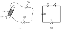
- FIG. 4 is a diagram (A) showing the connection of the first magnetic field generating unit and the power unit according to an embodiment of the present invention and an electrical circuit diagram (B) thereof.
- FIG. 5 is a diagram (A) showing the connection between the second magnetic field generating unit and the power unit according to an embodiment of the present invention and an electrical circuit diagram (B) thereof.
- FIGS. 6 and 7 are views illustrating flows of magnetic fields generated by the first magnetic field generator and the second magnetic field generator, respectively, according to an embodiment of the present invention.
- FIG 8 is a view showing the flow of the magnetic field generated by the magnetic field generating unit according to the comparative example.
- FIG. 9 is a view showing a magnetic field flow in a magnetic field driving system according to an embodiment of the present invention.
- FIG. 10 is a view showing a cross section of a magnetic core, a support frame, and a rail according to an embodiment of the present invention, respectively.
- FIG. 11 is a view showing a cross section of a magnetic core, a support frame, and frames according to another embodiment of the present invention.
- FIG. 12 is a cross-sectional view showing a magnetic core according to another embodiment of the present invention.
- FIG. 13 is a graph showing the results of analytically obtaining the strength of a magnetic field that can be generated when generating a high frequency magnetic field according to the application of a variable capacitor and a stacked magnetic structure.
- FIG. 14 is a view showing first and second magnetic cores according to another embodiment of the present invention.
- FIG. 15 is a front view showing the first and second magnetic cores of FIG. 14.
- FIG. 16 is a perspective view showing a first magnetic core according to another embodiment of the present invention.
- FIG. 17 is a front view showing the first magnetic core of FIG. 16.
- FIG. 18 is a perspective view showing a first magnetic core according to another embodiment of the present invention.
- FIG. 19 is a front view showing the first magnetic core of FIG. 18.
- 20 to 23 are views sequentially showing a driving method of a magnetic field driving system according to an embodiment of the present invention.
- 24 to 26 are perspective views illustrating a magnetic field driving system according to different embodiments of the present invention.
- the magnetic field driving system includes a rail; A first magnetic field generator installed on the rail; And a second magnetic field generating unit installed on the rail and facing the first magnetic field generating unit with a target region interposed therebetween, wherein the first magnetic field generating unit and the magnetic field generating unit apply a magnetic field to the target region. Can be created.
- a component when referred to as being on another component, it means that it may be formed directly on another component, or a third component may be interposed between them.
- a third component may be interposed between them.
- the thickness of the films and regions are exaggerated for effective description of the technical content.
- first, second, and third are used to describe various components, but these components should not be limited by these terms. These terms are only used to distinguish one component from another component. Therefore, what is referred to as the first component in one embodiment may be referred to as the second component in another embodiment.
- first component in one embodiment may be referred to as the second component in another embodiment.
- second component in another embodiment.
- Each embodiment described and illustrated herein also includes its complementary embodiment.
- 'and/or' is used to mean including at least one of the components listed before and after.
- FIG. 1 is a perspective view showing a magnetic field generating system according to an embodiment of the present invention
- FIG. 2 is a front view showing the magnetic image generating system of FIG. 1
- FIG. 3 is a right side view showing the magnetic field generating system of FIG. 1.
- the magnetic field generation system generates a magnetic field in the target region.
- the magnetic field generating system 10 includes a rail 100, a first magnetic field generating unit 200, a second magnetic field generating unit 300, a driving unit 400, and a power supply unit 500.
- the rail 100 has a predetermined length in one direction and is placed on the ground. According to an embodiment, the rail 100 may be provided with a magnetic material.
- the first magnetic field generating unit 200 and the second magnetic field generating unit 300 are respectively installed on the rail 100.
- the first magnetic field generating unit 200 and the second magnetic field generating unit 300 are arranged in a line along the length direction of the rail 100. At least a part of the space between the first magnetic phase generating unit 200 and the second magnetic field generating unit 300 is defined as a target area T.
- the first magnetic phase generating unit 200 and the second magnetic field generating unit 300 generate a magnetic field in the target region T.
- the first magnetic field generation unit 200 includes a first support frame 210, a first magnetic core 220, a first coil 230, and a first core variable module 240.
- the first support frame 210 is installed on the rail 100.
- the lower end of the first support frame 210 is installed on the rail 100.
- the first support frame 210 may be made of a magnetic material.
- the first support frame 210 is provided as a passage through the magnetic field generated by the first coil 230.
- the first support frame 210 has a ring shape having a predetermined radius, mecanic, and its central axis is arranged parallel to the longitudinal direction of the rail 100.
- the first support frame 210 may be provided as one frame.
- the first support frame 210 may be provided in a structure in which a pair of frames 211 and 212 are disposed facing each other at a predetermined distance.
- the first magnetic core 220 is supported by the first support frame 210 and extends from a predetermined position of the first support frame 210 toward the target area T.
- the first magnetic core 220 is a magnetic body having a predetermined shape, and its end is disposed toward the target region T.
- the first magnetic core 220 may have a cylindrical or polygonal column shape. At least one first magnetic core 220 may be provided. According to an embodiment, four first magnetic cores 220 are provided, and are spaced apart at predetermined intervals along the circumference of the first support frame 210. Each of the first magnetic cores 220 are disposed with their ends inclined toward the target area T.
- the first coils 230 are wound on the first magnetic cores 220, respectively.
- the first core variable module 240 is installed on the first support frame 210 and moves the first magnetic core 220.
- the first core variable module 240 moves the first magnetic core 220 along the circumference of the first support frame 210.
- the first core variable module 240 linearly moves the first magnetic core 220 in the direction of the central axis of the first magnetic core 220.
- the first core variable module 240 is provided in each of the first magnetic cores 220 and moves the first magnetic cores 220 individually. As the first magnetic cores 220 individually move along the circumference of the first support frame 210, the distance between the first magnetic cores 220 may be adjusted.
- the first core variable modules 240 may move the first magnetic cores 220 such that the intervals between the first magnetic cores 220 are the same.
- the first core variable modules 240 may move the first magnetic cores 220 such that gaps between the first magnetic cores 220 are different.
- the size of the target region T and the strength of the magnetic field formed in the target region T as the first magnetic cores 220 move forward or backward in the central axis direction Can be adjusted.
- the size of the target region T decreases, and a high-intensity magnetic field may be generated in the target region T.
- the first magnetic cores 220 move backward, the size of the target region T increases, and a magnetic field of relatively low intensity may be generated in the target region T.
- the size of the target region T and the intensity of the magnetic field formed in the target region T may be adjusted according to the linear movement of the first magnetic cores 220.
- the second magnetic field generator 300 includes a second support frame 310, a second magnetic core 320, a second coil 330, and a second core variable module 340.
- the second support frame 310 is installed on the rail 100.
- the second support frame 310 has the same shape, material, and size as the first support frame 210, and the lower end portion is placed on the rail 100.
- the second support frame 310 is disposed to face the first support frame 210, and its central axis is located on the same line as the central axis of the first support frame 210.
- the second magnetic core 320 is supported by the second support frame 310 and extends from the predetermined position of the second support frame 310 toward the target area T.
- the second magnetic core 320 is a magnetic body having the same shape as the first magnetic core 220, and an end thereof is disposed toward the target region T. At least one second magnetic core 320 may be provided. According to an embodiment, the second magnetic core 320 is provided in the same number as the first magnetic core 220.
- the second coil 330 is wound on the second magnetic cores 320, respectively.
- the second core variable module 340 is installed on the second support frame 310 and moves the second magnetic core 320.
- the second core variable module 340 moves the second magnetic core 320 along the circumference of the second support frame 310.
- the second core variable module 340 linearly moves the second magnetic core 320 in the direction of the central axis of the second magnetic core 320.
- the second core variable module 340 is provided in each of the second magnetic cores 320 and moves the second magnetic cores 320 individually.
- the driving unit 400 moves the first magnetic field generating unit 200 and the second magnetic field generating unit 300 along the rail 100.
- the driving unit 400 may individually move the first magnetic field generating unit 200 and the second magnetic field generating unit 300.
- the driving unit 400 includes a first driving unit 410 moving the first magnetic field generating unit 200 and a second driving unit 420 moving the second magnetic field generating unit 300.
- the first driving part 410 is installed on the rail 100 and is coupled to the first support frame 210.
- the first support frame 210 may move as the first driving unit 410 moves along the rail 100.
- the second driving part 420 is installed on the rail 100 and is coupled to the second support frame 310.
- the second support frame 310 may move as the second driving unit 420 moves along the rail 100.
- the position and size of the target area T may be adjusted according to the movement of the first support frame 210 and the second support frame 310.
- FIG. 4 is a diagram (A) showing the connection of the first magnetic field generating unit and the power supply unit according to an embodiment of the present invention and an electrical circuit diagram (B) thereof
- FIG. 5 is a second magnetic field generating unit according to an embodiment of the present invention It is the figure (A) which shows the connection of a power supply part, and its electrical circuit diagram (B).
- the power supply unit 500 supplies power to the first coil 230 and the second coil 330.
- the power supply unit 500 supplies power to the first circuit connected to the first coil 230 and the second circuit connected to the second coil 330, respectively.
- the first magnetic field generating unit 200 further includes a first variable capacitor 250 provided to the first circuit 201
- the second magnetic field generating unit 300 is a second circuit provided to the second circuit 301.
- the variable capacitor 250 is further included.
- the first and second circuits 201 and 301 are provided as closed circuits composed of power sources P1 and P2, resistors R1 and R2, inductances L1 and L2, and capacitances C1 and C2.
- the power supply (P1, P2) is the power supply unit 500
- the resistance (R1, R2) and the inductance (L1, L2) is the first and second magnetic core (220, 320) and the first and second coil (230) , 330
- capacitances C1 and C2 mean first and second variable capacitors 250 and 350.
- the first and second variable capacitors 250 and 350 control the capacitances C1 and C2 of the circuits 201 and 301 to influence the inductances L1 and L2 that reduce the strength of the magnetic field when generating a high-frequency magnetic field. Reduce. Thereby, the circuit can cause a resonance in which a magnetic field is maximized at a specific frequency. At this time, the resonance point can be adjusted by controlling the capacitances C1 and C2 of the first variable capacitor 230 and the second variable capacitor 330. Therefore, it may be possible to generate resonance at any frequency if the ranges of the capacitances C1 and C2 are sufficient.
- Vs is the magnitude of the applied voltage
- f is the frequency of the applied voltage
- Rc is the frequency of the applied voltage
- Lc is the resistance and inductance of the coil
- Cv is the capacitance of the variable capacitor.
- the maximum voltage is the resonant frequency of the closed circuit It is obtained from and the resonance frequency can be adjusted by a variable capacitor.
- FIG. 6 and 7 are diagrams respectively showing flows of magnetic fields generated by the first magnetic field generator and the second magnetic field generator according to an embodiment of the present invention
- FIG. 8 is a magnetic field generated by the magnetic field generator according to the comparative example It is a diagram showing the flow of.
- a magnetic field is generated in the first coil 230 by the power supplied from the power supply unit 500, and the generated magnetic field includes the first magnetic core 220 and the first support frame ( 210).
- the magnetic field M1 formed in the first magnetic core 220, the magnetic field M2 formed in the first support frame 210, and the magnetic field M3 formed in the target region T1 are closed magnetic circuits. To form.
- a magnetic field is generated in the second coil 330 by the power supplied from the power supply unit 500, and the generated magnetic field flows along the second magnetic core 320 and the second support frame 310.
- the magnetic field M1 formed in the second magnetic core 320, the magnetic field M2 formed in the second support frame 310, and the magnetic field M3 formed in the target region T2 form a closed magnetic circuit. do.
- FIG. 7 shows that the first and second magnetic cores 220 and 320 are linearly moved in the longitudinal direction by the first and second core variable modules 240 and 340 to form the target region T2 by fitting the lesion. That is, when compared with FIG. 6, a high-intensity magnetic field can be generated.
- FIG. 6 sets the size of the target region T1 to a diameter of 500 mm
- FIG. 7 sets the size of the target region T2 to a diameter of 300 mm, winding each coil 1,000 times, and applying a current of 10 A. Approved.
- the magnetic field strength at the center point Tc of the target regions T1 and T2 was 27 mT in FIG. 6 and 70 mT in FIG. 7.
- the magnetic field generator according to FIG. 8 forms an open magnetic circuit in which the magnetic field generated in the coil 21 is blocked from flowing in the magnetic cores 22.
- the size of the target region T1 is set to 500 mm in diameter as in FIG. 6, and the number of coils and the applied current are the same as above.
- the magnetic field strength is 10 mT at the center point Tc of the target region T1. appear.
- the closed magnetic circuit has an improved magnetic field generating ability than the open magnetic circuit.
- a magnetic field having a high intensity can be effectively generated.
- FIG. 9 is a view showing a magnetic field flow in a magnetic field driving system according to an embodiment of the present invention.
- a magnetic field flowing along the first support frame 210 may flow through the rail 100 made of a magnetic material to the second support frame 320. Conversely, the magnetic field flowing along the second support frame 320 may flow through the rail to the first support frame 210.
- the magnetic fields M1 and M2 formed in the first magnetic core 220 and the first support frame 210, the magnetic fields M3 formed in the rail 100, and the second magnetic core 320 and The magnetic fields M4 and M5 formed in the two support frames 310 and the magnetic fields Mt formed in the target region T form a closed magnetic circuit. The formation of the closed magnetic circuit maximizes the ability to generate a magnetic field in the target region T.
- FIG. 10 is a view showing cross sections of a magnetic core, a support frame, and a rail according to an embodiment of the present invention
- FIG. 11 is a cross section of a magnetic core, a support frame, and a rail according to another embodiment of the present invention, respectively It is a figure to show.
- the magnetic cores 220 and 320 have a cross section along the line A1-A2 in FIG. 3
- the support frames 210 and 310 have a cross section along the line B1-B2 in FIG.
- the rail 100 has a cross section along the line C1- in FIG.
- the cross section along line C2 is shown.
- the first and second magnetic cores 220 and 320, the first and second supporting frames 210 and 310, and the rail 100 may be configured as a single frame in a solid form. Can be.
- the first and second magnetic cores 220 and 320 are formed by stacking a plurality of first base frames F1, and the first and second support frames 210 and 310 are The plurality of second base frames F2 may be stacked, and the rail 100 may be configured by stacking a plurality of third base frames F3.
- the first to third base frames F1 to F3 are made of a magnetic material.
- the first and second magnetic cores 220 and 320 have a cylindrical shape as a whole, and the first base frames F1 have a structure in which thin plates having the same length as the first and second magnetic cores are stacked.
- the first and second magnetic cores 220 and 320 may have a quadrangular pillar shape, and in this case, the first and second magnetic cores 220 and 320 have a square cross section and thickness, as shown in FIG. 12.
- plate-shaped first base frames F1 having the same length.
- the second base frames F2 have the same radius as the first and second support frames 210 and 220 and are provided as thin ring-shaped plates, and their central axes are located on the same axis.
- the second base frames F2 are stacked with each other to form first and second support frames 210 and 220.
- the third base frame F3 thin plates having the same length as the rail 100 are stacked in the width direction of the rail 100 to constitute the rail 100.
- the first and second magnetic cores 220 and 320, the first and second supporting frames 210 and 310, and the eddy currents inside the rail 100 Is generated, and these eddy currents EC1 and EC2 may be factors that reduce the strength of the high-frequency magnetic field.
- the eddy current ( The area through which EC1) can flow increases, and the intensity of the eddy current EC1 increases.
- the first and second magnetic cores 220 and 320, the first and second support frames 210 and 310, and the rail 100 are the base frames F1 and F2 , F3), eddy currents EC2 are respectively generated.
- the base frames F1, F2, and F3 each have a relatively small cross-sectional area, the area through which the eddy current EC2 can flow is reduced. Due to this, the intensity of the eddy current EC2 flowing inside the base frames F1, F2, and F3 is reduced, and the effect of reducing the magnetic field intensity due to the eddy current can be reduced.
- the first graph (A) represents the strength of the magnetic field according to an embodiment in which the variable capacitor and the stacked magnetic structure are not applied
- the second graph (B) is a variable capacitor as shown in FIG. 10 and the stacked magnetic structure is not applied.
- the magnetic field strength according to the embodiment is illustrated
- the third graph C represents the magnetic field strength according to the embodiment in which both the variable capacitor and the stacked magnetic structure are applied as shown in FIG. 11.
- the resistance of the magnetic field generator is set to about 8 ⁇ , and the inductance is set to about 0.8H, and the intensity of the current is applied to generate a magnetic field of about 200 mT intensity in the target region.
- the difference in the intensity of the magnetic field that can be generated rapidly increases as the frequency of the magnetic field increases.
- a variable capacitor and a stacked magnetic structure are essential to generate a high-power high-frequency magnetic field.
- FIG. 14 is a view showing first and second magnetic cores according to another embodiment of the present invention
- FIG. 15 is a plane view showing first and second magnetic cores of FIG. 14.
- the first magnetic core and the second magnetic core may be provided with the same structure, and the first magnetic core will be described as an example below.
- the first magnetic core 220 includes a first core housing 211, a first auxiliary core 213, and a first core driver (not shown).
- the first coil 230 is wound on the outer surface, and a space is formed therein.
- An opening 211a is formed at one end of the first core housing 211. The opening 211a communicates with the interior of the first core housing 211.
- the first auxiliary core 213 has a smaller volume than the first core housing 211 and is inserted into the first core housing 211 through the opening 211a.
- the first auxiliary core 213 is made of a magnetic material.
- the first auxiliary core 213 may have a column shape having a diameter corresponding to the opening 211a.
- the first auxiliary core 213 may have a central axis C on the same line as the central axis C of the first core housing 211.
- the first core driving unit linearly moves the first auxiliary core 213 in the direction of its central axis C. Accordingly, the tip of the first auxiliary core 213 may be located at the same point as one end of the first core housing 211 or may protrude toward the front of the first core housing 211.
- the magnetic field generated by the first coil 230 flows along the first core housing 211 and the first auxiliary core 213 to generate a magnetic field in the target region T.
- the first magnetic core 210 changes the position of the end of the first magnetic core 210 according to the linear movement of the first auxiliary core 213, and accordingly, the strength and distribution of the generated magnetic field can be variously adjusted. .
- by moving the first auxiliary core 213 having a relatively small weight load generation due to movement can be minimized.
- FIG. 16 is a perspective view showing a first magnetic core according to another embodiment of the present invention
- FIG. 17 is a front view showing the first magnetic core of FIG. 16.
- the first auxiliary core 213 has its central axis C1 spaced a predetermined distance from the central axis C of the first core housing 211, so that the first core housing 211 It is arranged parallel to the central axis (C).
- the first auxiliary core 213 is linearly moved in the direction of its central axis C1 by the first core driver.
- FIG. 18 is a perspective view showing a first magnetic core according to another embodiment of the present invention
- FIG. 19 is a front view showing the first magnetic core of FIG. 18.
- a plurality of openings 211a and 211b may be formed at one end of the first core housing 211.
- the openings 211a and 211b may have the same size.
- the openings 211a and 211b may have different sizes.
- two openings 211a and 211b are formed at one end of the first core housing 211, and the sizes of the openings 211a and 211b may be the same.
- First auxiliary cores 213 are inserted into the openings 211a and 211b, respectively.
- the first auxiliary core 213 has a diameter corresponding to the openings 211a and 211b to be inserted.
- the first auxiliary cores 211a and 211b have their central axes C1 and C2 spaced a predetermined distance from the central axis C of the first core housing 211, such that the central axis C of the first core housing 211 ).
- the first core driving unit individually moves the first auxiliary cores 213 linearly in the central axes C1 and C2. Accordingly, the lengths of the first auxiliary cores 213 protruding forward of the first core housing 211 may be adjusted.
- 20 to 23 are views sequentially showing a driving method of a magnetic field driving system according to an embodiment of the present invention.
- the method of driving the magnetic field driving system 10 first places the patient 20 on the bed 30. Then, the positions of the first magnetic field generator 200 and the second magnetic field generator 300 are adjusted so that the lesion portion of the patient 20 is located in the target region of the magnetic field driving system 10. In this embodiment, the head region of the patient 20 is located in the target region for the brain disease treatment of the patient 20.
- the first magnetic field generating unit 200 and the second magnetic field generating unit 300 are linearly moved along the rail 100 by the driving of the first driving unit 410 and the second driving unit 420, so that the lesion of the patient 20 It is located in the additional target area.
- the first and second core variable modules 240 and 340 move the first and second magnetic cores 220 and 320 along the first and second support frames 210 and 310, and the first and second magnetics
- the positions of the first and second magnetic cores 220 and 320 are aligned by linearly moving the cores 220 and 320 in the central axis direction. Thereby, the target region can be optimized for the lesion.
- power is applied to the first and second coils 230 and 330.
- a magnetic field is generated in the target region by application of power.
- the position of the magnetic robot inserted into the body of the patient 20 is tracked, and the motion of the magnetic robot is performed using the magnetic field generated by the magnetic field driving system 10 Can be controlled.
- the strength of the magnetic field generated in the target region may be increased by the formation of the closed magnetic circuit.
- 24 to 26 are perspective views illustrating a magnetic field driving system according to different embodiments of the present invention.
- the first and second support frames of the magnetic field driving system may have a ring shape or an arc shape.
- the first support frame 210a may have a ring shape
- the second support frame 310a may have an arc shape with an open top.
- both the first and second support frames 210b and 310b may have an arc shape with an open top.
- both the first and second support frames 210b and 310b may have an arc shape in which upper and lower portions are opened.
- the combination of the first and second support frames is not limited to this, and may be changed to various combinations of the above-described ring shape and arc shape.
- first and second support frames 210a to 210c and 310a to 310c maximize compatibility between an X-ray imaging device composed of a C-arm and the like and a magnetic field driving system.
- first and second support frames 210a to 210c and 310a to 310c are made lighter.
- the magnetic field driving system may generate a magnetic field in a target area to drive a magnetic robot.
Abstract
A magnetic field drive system is disclosed. The magnetic field drive system comprises: a rail; a first magnetic field generating unit provided on the rail; and a second magnetic field generating unit provided on the rail, and arranged to face the first magnetic field generating unit with a target region therebetween, wherein the first magnetic field generating unit and the second magnetic field generating unit can generate magnetic field in the target region.
Description
본 발명은 자기장 구동 시스템에 관련된 것으로, 보다 상세하게는 타겟 영역에 자기장을 생성할 수 있는 자기장 구동 시스템에 관한 것이다.The present invention relates to a magnetic field driving system, and more particularly, to a magnetic field driving system capable of generating a magnetic field in a target region.
내부에 자석이 장착된 마그네틱 로봇은 자기장 구동 시스템이 생성하는 외부 자기장에 의해 자기토크와 자기력을 받아 구동하게 되며, 원격으로 정밀제어가 가능하여 많은 부위에 적용 및 연구개발이 진행되고 있다. 대표적으로 소화기계에 적용된 자기 구동형 캡슐형 내시경, 심장 부정맥 치료에 적용된 마그네틱 카테터 등이 있으며, 이 외에도 폐색성 혈관 치료를 위한 혈관치료용 마그네틱 로봇, 안구 내 약물전달을 위한 마이크로 로봇, 조직 내 표적 약물전달을 위한 자기 나노 입자 등이 있다.The magnetic robot equipped with a magnet is driven by receiving magnetic torque and magnetic force by an external magnetic field generated by a magnetic field driving system, and it can be precisely controlled remotely, and is applied and researched and developed in many areas. Typical examples include self-driven capsule endoscopes applied to the digestive system, magnetic catheters applied to the treatment of cardiac arrhythmias, etc.In addition, magnetic robots for vascular therapy to treat occlusive blood vessels, micro-robots for intraocular drug delivery, and targets in tissues Magnetic nanoparticles for drug delivery.
이와 같이 마그네틱 로봇이 적용되는 인체 부위 및 병변부의 위치는 매우 다양하다. 이러한 마그네틱 로봇의 구동 및 제어의 핵심은 외부 자기장을 생성하는 자기장 구동 시스템이다. 그러나 기존의 자기장 구동 시스템들은 자기장을 생성하는 전자석의 위치 및 배치형태가 고정되어 있어 병변부의 위치 및 특성을 고려하지 못해 비효율적으로 자기장을 생성 및 제어하였다. 그리고 자성 코어 등 자성 구조가 갖는 자기적 특성으로 인해 고출력의 고주파 자기장을 생성하지 못하는 한계들이 있었다. 이러한 자기장 구동 시스템의 한계는 마그네틱 로봇이 적용 가능한 질환 및 생성 가능한 운동 등의 한계로 이어진다.As described above, the positions of the human body part and the lesion part to which the magnetic robot is applied vary. The core of the driving and control of the magnetic robot is a magnetic field driving system that generates an external magnetic field. However, the existing magnetic field driving systems have generated and controlled the magnetic field inefficiently because the position and arrangement of the electromagnet generating the magnetic field are fixed and the position and characteristics of the lesion are not considered. In addition, due to the magnetic properties of a magnetic structure such as a magnetic core, there are limitations in that a high-power high-frequency magnetic field cannot be generated. The limitations of the magnetic field driving system lead to limitations such as a disease that a magnetic robot is applicable to and a movement that can be generated.
본 발명은 병변부의 위치 및 특성에 따라 자기장 생성부의 위치 및 배치를 최적화할 수 있는 자기장 구동 시스템을 제공한다.The present invention provides a magnetic field driving system capable of optimizing the position and arrangement of the magnetic field generator according to the position and characteristics of the lesion.
또한, 본 발명은 고출력의 고주파 자기장을 생성할 수 있는 자기장 구동 시스템을 제공한다.In addition, the present invention provides a magnetic field driving system capable of generating a high-power high-frequency magnetic field.
본 발명에 따른 자기장 구동 시스템은 레일; 상기 레일 상에 설치되는 제1자기장 생성부; 및 상기 레일 상에 설치되며, 타겟 영역을 사이에 두고 상기 제1자기장 생성부와 마주 배치되는 제2자기장 생성부를 포함하되, 상기 제1자자장 생성부와 상기 자기장 생성부는 상기 타겟 영역에 자기장을 생성할 수 있다.The magnetic field driving system according to the present invention includes a rail; A first magnetic field generator installed on the rail; And a second magnetic field generating unit installed on the rail and facing the first magnetic field generating unit with a target region interposed therebetween, wherein the first magnetic field generating unit and the magnetic field generating unit apply a magnetic field to the target region. Can be created.
또한, 상기 레일을 따라 상기 제1자기장 생성부와 상기 제2자기장 생성부를 이동시키는 구동부를 더 포함할 수 있다.In addition, a driving unit for moving the first magnetic field generating unit and the second magnetic field generating unit along the rail may be further included.
또한, 상기 제1자기장 생성부는, 상기 레일 상에 설치되는 제1지지 프레임; 상기 제1지지 프레임에 지지되며, 그 끝단이 상기 타겟 영역을 향해 배치되는 적어도 하나 이상의 제1자성 코어; 및 상기 제1자성 코어들 각각에 권선되는 제1코일을 포함하고, 상기 제2자기장 생성부는, 상기 레일 상에 설치되며, 상기 제1지지 프레임과 마주 배치되는 제2지지 프레임; 상기 제2지지 프레임에 지지되며, 그 끝단이 상기 타겟 영역을 향해 배치되는 적어도 하나 이상의 제2자성 코어; 및 상기 제2자성 코어들 각각에 권선되는 제2코일을 포함할 수 있다.In addition, the first magnetic field generating unit, a first support frame installed on the rail; At least one first magnetic core supported on the first support frame, the ends of which are disposed toward the target area; And a first coil wound around each of the first magnetic cores, the second magnetic field generating unit being installed on the rail, and a second support frame disposed opposite the first support frame; At least one second magnetic core supported on the second support frame, the ends of which are disposed toward the target area; And a second coil wound on each of the second magnetic cores.
또한, 상기 제1자기장 생성부는, 상기 제1지지 프레임을 따라 상기 제1자성 코어를 이동시키는 제1 코어 가변 모듈을 포함하고, 상기 제2자기장 생성부는, 상기 제2지지 프레임을 따라 상기 제2자성 코어를 이동시키는 제2 코어 가변 모듈을 포함할 수 있다.In addition, the first magnetic field generating unit includes a first core variable module for moving the first magnetic core along the first supporting frame, and the second magnetic field generating unit includes the second supporting frame along the second supporting frame. It may include a second core variable module for moving the magnetic core.
또한, 상기 제1코어 가변 모듈은 복수 개의 상기 제1자성 코어들을 개별적으로 이동시키고, 상기 제2코어 가변 모듈은 복수 개의 상기 제2자성 코어들을 개별적으로 이동시킬 수 있다.In addition, the first core variable module may individually move the plurality of first magnetic cores, and the second core variable module may individually move the plurality of second magnetic cores.
또한, 상기 제1코어 가변 모듈은 상기 제1자성 코어의 중심축 방향으로 상기 제1자성 코어를 직선 이동시키고, 상기 제2코어 가변 모듈은 상기 제2자성 코어의 중심축 방향으로 상기 제2자성 코어를 직선 이동시킬 수 있다.In addition, the first core variable module linearly moves the first magnetic core in the direction of the central axis of the first magnetic core, and the second core variable module moves the second magnetic in the center axis direction of the second magnetic core. The core can be moved straight.
또한, 상기 제1지지 프레임과 상기 제2지지 프레임 각각은 크기가 동일한 링 형상을 가지고, 그 중심이 동일 축 상에 위치할 수 있다.In addition, each of the first support frame and the second support frame has a ring shape having the same size, and its center may be located on the same axis.
또한, 상기 제1자성 코어, 상기 제2자성 코어, 상기 제1지지 프레임, 제2지지 프레임, 그리고 상기 레일은 자성 재질로 제공되며, 상기 타겟 영역에 형성된 자기장과, 상기 제1자성 코어, 상기 제1지지 프레임, 상기 레일, 상기 제2지지 프레임, 그리고 제2자성 코어에 각각 형성된 자기장은 폐자기회로를 형성할 수 있다.In addition, the first magnetic core, the second magnetic core, the first support frame, the second support frame, and the rail is provided with a magnetic material, the magnetic field formed in the target region, the first magnetic core, the The magnetic fields formed in the first support frame, the rail, the second support frame, and the second magnetic core may form a closed magnetic circuit.
또한, 제1회로를 통해 상기 제1코일에 전원을 공급하고, 제2회로를 통해 상기 제2코일에 전원을 공급하는 전원부; 및 상기 제1회로 및 상기 제2회로 각각에 제공되는 가변 커패시터를 포함할 수 있다.In addition, a power supply unit for supplying power to the first coil through a first circuit, and supplying power to the second coil through a second circuit; And a variable capacitor provided in each of the first circuit and the second circuit.
또한, 상기 제1지지 프레임은, 자성 재질로 제공되는 복수 개의 베이스 프레임들이 적층된 구조를 가질 수 있다.In addition, the first support frame may have a structure in which a plurality of base frames provided with a magnetic material are stacked.
또한, 상기 베이스 프레임들은 상기 제1지지 프레임과 동일한 반경을 가지며, 동일한 중심축 상에 위치할 수 있다.In addition, the base frames have the same radius as the first support frame and may be located on the same central axis.
또한, 상기 제1자성 코어는, 자성 재질로 제공되는 복수 개의 베이스 프레임들이 적층된 구조로 제공되며, 상기 베이스 프레임들은 상기 제1자성 코어와 동일한 길이를 가질 수 있다.In addition, the first magnetic core is provided in a structure in which a plurality of base frames made of a magnetic material are stacked, and the base frames may have the same length as the first magnetic core.
또한, 상기 레일은, 자성 재질로 제공되는 복수 개의 베이스 프레임들이 적층된 구조로 제공되며, 상기 베이스 프레임들은 상기 레일과 동일한 길이를 가질 수 있다.In addition, the rail is provided in a structure in which a plurality of base frames made of a magnetic material are stacked, and the base frames may have the same length as the rail.
또한, 상기 제1자성 코어는, 외측면에 상기 제1코일이 권선되고, 내부 공간을 가지며, 일 단부에 개구가 형성된 제1코어 하우징; 상기 개구를 통해 상기 내부 공간으로 삽입되는 제1보조 코어; 및 상기 제1보조 코어를 그 중심축 방향으로 직선 이동시키는 제1코어 구동부를 포함할 수 있다.In addition, the first magnetic core, the first coil is wound on the outer surface, having an inner space, a first core housing having an opening formed at one end; A first auxiliary core inserted into the interior space through the opening; And it may include a first core driving unit for linearly moving the first auxiliary core in the direction of the central axis.
또한, 상기 제1코어 하우징의 중심축과 상기 제1보조 코어의 중심축은 동일 선상에 위치할 수 있다.In addition, the central axis of the first core housing and the central axis of the first auxiliary core may be located on the same line.
또한, 상기 제1코어 하우징의 중심축과 상기 제1보조 코어의 중심축은 서로 평행하게 배열될 수 있다.In addition, the central axis of the first core housing and the central axis of the first auxiliary core may be arranged parallel to each other.
또한, 상기 제1코어 하우징의 일 단부에는 상기 개구가 복수 개 형성되고, 상기 제1보조 코어는 복수 개가 상기 개구들 각각에 삽입되며, 상기 제1코어 구동부는 상기 제1보조 코어들을 개별적으로 이동시킬 수 있다.In addition, a plurality of openings are formed at one end of the first core housing, a plurality of the first auxiliary cores are inserted into each of the openings, and the first core driving unit individually moves the first auxiliary cores. I can do it.
또한, 상기 개구들은 서로 상이한 크기를 가지며, 상기 제1보조 코어들은 상기 개구들 각각에 상응하는 크기를 가질 수 있다.In addition, the openings may have different sizes from each other, and the first auxiliary cores may have a size corresponding to each of the openings.
본 발명에 의하면, 자성 코어들이 지지 프레임을 따라 이동하거나, 그 축방향으로 직선이동 가능하므로, 병변부의 위치 및 특성에 따라 자기장의 생성을 제어할 수 있다.According to the present invention, since the magnetic cores can move along the support frame or linearly move in the axial direction, it is possible to control the generation of a magnetic field according to the location and characteristics of the lesion.
또한, 본 발명에 의하면, 폐자기회로의 생성, 가변 커패시터와 적층형 자성 구조의 제공으로, 타겟 영역에 고출력의 고주파 자기장을 생성할 수 있다.In addition, according to the present invention, by generating a closed magnetic circuit and providing a variable capacitor and a stacked magnetic structure, a high-power high-frequency magnetic field can be generated in a target region.
도 1은 본 발명의 실시 예에 따른 자기장 생성 시스템을 나타내는 사시도이다.1 is a perspective view showing a magnetic field generating system according to an embodiment of the present invention.
도 2는 도 1의 자기상 생성 시스템을 나타내는 정면도이다.FIG. 2 is a front view showing the magnetic image generating system of FIG. 1.
도 3은 도 1의 자기장 생성 시스템을 나타내는 우측면도이다.3 is a right side view of the magnetic field generating system of FIG. 1.
도 4는 본 발명의 실시 예에 따른 제1자기장 생성부와 전원부의 연결을 나타내는 도면(A)과 이의 전기 회로도(B)이다.4 is a diagram (A) showing the connection of the first magnetic field generating unit and the power unit according to an embodiment of the present invention and an electrical circuit diagram (B) thereof.
도 5는 본 발명의 실시 예에 따른 제2자기장 생성부와 전원부의 연결을 나타내는 도면(A)과 이의 전기 회로도(B)이다.5 is a diagram (A) showing the connection between the second magnetic field generating unit and the power unit according to an embodiment of the present invention and an electrical circuit diagram (B) thereof.
도 6 및 도 7은 본 발명의 실시 예에 따라 제1자기장 생성부와 제2자기장 생성부에서 생성되는 자기장의 흐름을 각각 나타내는 도면이다.6 and 7 are views illustrating flows of magnetic fields generated by the first magnetic field generator and the second magnetic field generator, respectively, according to an embodiment of the present invention.
도 8은 비교 예에 따른 자기장 생성부에서 생성되는 자기장의 흐름을 나타내는 도면이다.8 is a view showing the flow of the magnetic field generated by the magnetic field generating unit according to the comparative example.
도 9는 본 발명의 실시 예에 따라 자기장 구동 시스템에서의 자기장 흐름을 나타내는 도면이다.9 is a view showing a magnetic field flow in a magnetic field driving system according to an embodiment of the present invention.
도 10은 본 발명의 일 실시 예에 따른 자성 코어, 지지 프레임, 그리고 레일의 단면을 각각 나타내는 도면이다.10 is a view showing a cross section of a magnetic core, a support frame, and a rail according to an embodiment of the present invention, respectively.
도 11은 본 발명의 다른 실시 예에 따른 자성 코어, 지지 프레임, 그리고 레일의 단면을 각각 나타내는 도면이다.11 is a view showing a cross section of a magnetic core, a support frame, and frames according to another embodiment of the present invention.
도 12는 본 발명의 또 다른 실시 예에 따른 자성 코어를 나타내는 단면도이다.12 is a cross-sectional view showing a magnetic core according to another embodiment of the present invention.
도 13은 가변 커패시터와 적층형 자성 구조의 적용에 따라 고주파 자기장 생성 시 생성 가능한 자기장의 세기를 해석적으로 구한 결과를 나타내는 그래프이다.13 is a graph showing the results of analytically obtaining the strength of a magnetic field that can be generated when generating a high frequency magnetic field according to the application of a variable capacitor and a stacked magnetic structure.
도 14는 본 발명의 다른 실시 예에 따른 제1 및 제2자성 코어를 나타내는 도면이다.14 is a view showing first and second magnetic cores according to another embodiment of the present invention.
도 15는 도 14의 제1 및 제2자성 코어를 나타내는 정면도이다.15 is a front view showing the first and second magnetic cores of FIG. 14.
도 16은 본 발명의 또 다른 실시 예에 따른 제1자성 코어를 나타내는 사시도이다.16 is a perspective view showing a first magnetic core according to another embodiment of the present invention.
도 17은 도 16의 제1자성 코어를 나타내는 정면도이다.17 is a front view showing the first magnetic core of FIG. 16.
도 18은 본 발명의 또 다른 실시 예에 따른 제1자성 코어를 나타내는 사시도이다.18 is a perspective view showing a first magnetic core according to another embodiment of the present invention.
도 19는 도 18의 제1자성 코어를 나타내는 정면도이다.19 is a front view showing the first magnetic core of FIG. 18.
도 20 내지 도 23은 본 발명의 실시 예에 따른 자기장 구동 시스템의 구동 방법을 순차적으로 나타내는 도면이다.20 to 23 are views sequentially showing a driving method of a magnetic field driving system according to an embodiment of the present invention.
도 24 내지 도 26은 본 발명의 서로 다른 실시 예에 따른 자기장 구동 시스템을 나타내는 사시도이다.24 to 26 are perspective views illustrating a magnetic field driving system according to different embodiments of the present invention.
본 발명에 따른 자기장 구동 시스템은 레일; 상기 레일 상에 설치되는 제1자기장 생성부; 및 상기 레일 상에 설치되며, 타겟 영역을 사이에 두고 상기 제1자기장 생성부와 마주 배치되는 제2자기장 생성부를 포함하되, 상기 제1자자장 생성부와 상기 자기장 생성부는 상기 타겟 영역에 자기장을 생성할 수 있다.The magnetic field driving system according to the present invention includes a rail; A first magnetic field generator installed on the rail; And a second magnetic field generating unit installed on the rail and facing the first magnetic field generating unit with a target region interposed therebetween, wherein the first magnetic field generating unit and the magnetic field generating unit apply a magnetic field to the target region. Can be created.
이하, 첨부된 도면들을 참조하여 본 발명의 바람직한 실시 예를 상세히 설명할 것이다. 그러나 본 발명의 기술적 사상은 여기서 설명되는 실시 예에 한정되지 않고 다른 형태로 구체화 될 수도 있다. 오히려, 여기서 소개되는 실시 예는 개시된 내용이 철저하고 완전해질 수 있도록 그리고 당업자에게 본 발명의 사상이 충분히 전달될 수 있도록 하기 위해 제공되는 것이다.Hereinafter, preferred embodiments of the present invention will be described in detail with reference to the accompanying drawings. However, the technical spirit of the present invention is not limited to the embodiments described herein and may be embodied in other forms. Rather, the embodiments introduced herein are provided to ensure that the disclosed contents are thorough and complete and that the spirit of the present invention is sufficiently conveyed to those skilled in the art.
본 명세서에서, 어떤 구성요소가 다른 구성요소 상에 있다고 언급되는 경우에 그것은 다른 구성요소 상에 직접 형성될 수 있거나 또는 그들 사이에 제 3의 구성요소가 개재될 수도 있다는 것을 의미한다. 또한, 도면들에 있어서, 막 및 영역들의 두께는 기술적 내용의 효과적인 설명을 위해 과장된 것이다. In the present specification, when a component is referred to as being on another component, it means that it may be formed directly on another component, or a third component may be interposed between them. In addition, in the drawings, the thickness of the films and regions are exaggerated for effective description of the technical content.
또한, 본 명세서의 다양한 실시 예 들에서 제1, 제2, 제3 등의 용어가 다양한 구성요소들을 기술하기 위해서 사용되었지만, 이들 구성요소들이 이 같은 용어들에 의해서 한정되어서는 안 된다. 이들 용어들은 단지 어느 구성요소를 다른 구성요소와 구별시키기 위해서 사용되었을 뿐이다. 따라서, 어느 한 실시 예에 제 1 구성요소로 언급된 것이 다른 실시 예에서는 제 2 구성요소로 언급될 수도 있다. 여기에 설명되고 예시되는 각 실시 예는 그것의 상보적인 실시 예도 포함한다. 또한, 본 명세서에서 '및/또는'은 전후에 나열한 구성요소들 중 적어도 하나를 포함하는 의미로 사용되었다.In addition, in various embodiments of the present specification, terms such as first, second, and third are used to describe various components, but these components should not be limited by these terms. These terms are only used to distinguish one component from another component. Therefore, what is referred to as the first component in one embodiment may be referred to as the second component in another embodiment. Each embodiment described and illustrated herein also includes its complementary embodiment. In addition, in this specification,'and/or' is used to mean including at least one of the components listed before and after.
명세서에서 단수의 표현은 문맥상 명백하게 다르게 뜻하지 않는 한 복수의 표현을 포함한다. 또한, "포함하다" 또는 "가지다" 등의 용어는 명세서상에 기재된 특징, 숫자, 단계, 구성요소 또는 이들을 조합한 것이 존재함을 지정하려는 것이지, 하나 또는 그 이상의 다른 특징이나 숫자, 단계, 구성요소 또는 이들을 조합한 것들의 존재 또는 부가 가능성을 배제하는 것으로 이해되어서는 안 된다. 또한, 본 명세서에서 "연결"은 복수의 구성 요소를 간접적으로 연결하는 것, 및 직접적으로 연결하는 것을 모두 포함하는 의미로 사용된다. In the specification, a singular expression includes a plural expression unless the context clearly indicates otherwise. Also, terms such as “include” or “have” are intended to indicate the presence of features, numbers, steps, elements, or combinations thereof described in the specification, and one or more other features, numbers, steps, or configurations. It should not be understood as excluding the possibility of the presence or addition of elements or combinations thereof. In addition, in the present specification, “connecting” is used in a sense to include both indirectly connecting a plurality of components, and directly connecting.
또한, 하기에서 본 발명을 설명함에 있어 관련된 공지 기능 또는 구성에 대한 구체적인 설명이 본 발명의 요지를 불필요하게 흐릴 수 있다고 판단되는 경우에는 그 상세한 설명은 생략할 것이다.In addition, in the following description of the present invention, when it is determined that detailed descriptions of related known functions or configurations may unnecessarily obscure the subject matter of the present invention, detailed descriptions thereof will be omitted.
도 1은 본 발명의 실시 예에 따른 자기장 생성 시스템을 나타내는 사시도이고, 도 2는 도 1의 자기상 생성 시스템을 나타내는 정면도이고, 도 3은 도 1의 자기장 생성 시스템을 나타내는 우측면도이다.1 is a perspective view showing a magnetic field generating system according to an embodiment of the present invention, FIG. 2 is a front view showing the magnetic image generating system of FIG. 1, and FIG. 3 is a right side view showing the magnetic field generating system of FIG. 1.
도 1 내지 도 3을 참조하면, 자기장 생성 시스템은 타겟 영역에 자기장을 생성한다. 자기장 생성 시스템(10)은 레일(100), 제1자기장 생성부(200), 제2자기장 생성부(300), 구동부(400), 그리고 전원부(500)를 포함한다.1 to 3, the magnetic field generation system generates a magnetic field in the target region. The magnetic field generating system 10 includes a rail 100, a first magnetic field generating unit 200, a second magnetic field generating unit 300, a driving unit 400, and a power supply unit 500.
레일(100)은 일 방향으로 소정 길이를 가지며, 지면에 놓인다. 실시 예에 의하면, 레일(100)은 자성 재질로 제공될 수 있다.The rail 100 has a predetermined length in one direction and is placed on the ground. According to an embodiment, the rail 100 may be provided with a magnetic material.
제1자기장 생성부(200)와 제2자기장 생성부(300)는 레일(100) 상에 각각 설치된다. 제1자기장 생성부(200)와 제2자기장 생성부(300)은 레일(100)의 길이 방향을 따라 일렬 배치된다. 제1자기상 생성부(200)와 제2자기장 생성부(300)의 사이 공간 중 적어도 일부 영역은 타겟 영역(T)으로 정의된다. 제1자기상 생성부(200)와 제2자기장 생성부(300)는 타겟 영역(T)에 자기장을 생성한다.The first magnetic field generating unit 200 and the second magnetic field generating unit 300 are respectively installed on the rail 100. The first magnetic field generating unit 200 and the second magnetic field generating unit 300 are arranged in a line along the length direction of the rail 100. At least a part of the space between the first magnetic phase generating unit 200 and the second magnetic field generating unit 300 is defined as a target area T. The first magnetic phase generating unit 200 and the second magnetic field generating unit 300 generate a magnetic field in the target region T.
제1자기장 생성부(200)는 제1지지 프레임(210), 제1자성 코어(220), 제1코일(230), 그리고 제1코어 가변 모듈(240)을 포함한다.The first magnetic field generation unit 200 includes a first support frame 210, a first magnetic core 220, a first coil 230, and a first core variable module 240.
제1지지 프레임(210)은 레일(100) 상에 설치된다. 제1지지 프레임(210)은 하단부가 레일(100) 상에 설치된다. 제1지지 프레임(210)은 자성 재질로 제공될 수 있다. 제1지지 프레임(210)은 제1코일(230)에서 생성된 자기장이 지나는 통로로 제공된다. 실시 예에 의하면, 제1지지 프레임(210)은 소정 반경을 갖는 링 형상을 가지며, 그 중심축이 레일(100)의 길이 방향과 나란하게 배치된다. 일 예에 의하면, 제1지지 프레임(210)은 하나의 프레임으로 제공될 수 있다. 이와 달리, 제1지지 프레임(210)은 한 쌍의 프레임(211, 212)이 소정 거리를 두고 마주 배치된 구조로 제공될 수 있다.The first support frame 210 is installed on the rail 100. The lower end of the first support frame 210 is installed on the rail 100. The first support frame 210 may be made of a magnetic material. The first support frame 210 is provided as a passage through the magnetic field generated by the first coil 230. According to an embodiment, the first support frame 210 has a ring shape having a predetermined radius, „, and its central axis is arranged parallel to the longitudinal direction of the rail 100. According to an example, the first support frame 210 may be provided as one frame. Alternatively, the first support frame 210 may be provided in a structure in which a pair of frames 211 and 212 are disposed facing each other at a predetermined distance.
제1자성 코어(220)는 제1지지 프레임(210)에 지지되며, 제1지지 프레임(210)의 소정 위치로부터 타겟 영역(T)을 향해 연장된다. 제1자성 코어(220)는 소정 형상의 자성체로, 그 끝단이 타겟 영역(T)을 향해 배치된다. 제1자성 코어(220)는 원기둥 또는 다각 기둥 형상을 가질 수 있다. 제1자성 코어(220)는 적어도 하나 이상 제공될 수 있다. 실시 예에 의하면, 제1자성 코어(220)는 4개 제공되며, 제1지지 프레임(210)의 둘레를 따라 소정 간격 이격하여 배치된다. 각각의 제1자성 코어(220)들은 그 끝단이 타겟 영역(T)을 향해 경사지게 배치된다. The first magnetic core 220 is supported by the first support frame 210 and extends from a predetermined position of the first support frame 210 toward the target area T. The first magnetic core 220 is a magnetic body having a predetermined shape, and its end is disposed toward the target region T. The first magnetic core 220 may have a cylindrical or polygonal column shape. At least one first magnetic core 220 may be provided. According to an embodiment, four first magnetic cores 220 are provided, and are spaced apart at predetermined intervals along the circumference of the first support frame 210. Each of the first magnetic cores 220 are disposed with their ends inclined toward the target area T.
제1코일(230)은 제1자성 코어(220)들에 각각 권선된다.The first coils 230 are wound on the first magnetic cores 220, respectively.
제1코어 가변 모듈(240)은 제1지지 프레임(210)에 설치되며, 제1자성 코어(220)를 이동시킨다. 제1코어 가변 모듈(240)은 제1지지 프레임(210)의 둘레를 따라 제1자성 코어(220)를 이동시킨다. 또한, 제1코어 가변 모듈(240)은 제1자성 코어(220)의 중심축 방향으로 제1자성 코어(220)를 직선 이동시킨다. 제1코어 가변 모듈(240)은 제1자성 코어(220)들 각각에 제공되며, 제1자성 코어(220)들을 개별적으로 이동시킨다. 제1자성 코어(220)들이 제1지지 프레임(210)의 둘레를 따라 개별적으로 이동함에 따라, 제1자성 코어(220)들의 사이 간격이 조절될 수 있다. 제1코어 가변 모듈(240)들은 제1자성 코어(220)들의 사이 간격이 동일하도록 제1자성 코어(220)들을 이동시킬 수 있다. 이와 달리, 제1코어 가변 모듈(240)들은 제1자성 코어(220)들의 사이 간격이 상이하도록 제1자성 코어(220)들을 이동시킬 수 있다. 제1코어 가변 모듈(240)들의 구동으로, 제1자성 코어(220)들이 그 중심축 방향으로 전진 또는 후퇴 이동함에 타겟 영역(T)의 크기 및 상기 타겟 영역(T)에 형성되는 자기장의 세기가 조절될 수 있다. 구체적으로 제1자성 코어(220)들이 전진 이동할 경우, 타겟 영역(T)의 크기가 감소하고, 상기 타겟 영역(T)에는 높은 세기의 자기장이 생성될 수 있다. 반면, 제1자성 코어(220)들이 후퇴 이동할 경우, 타겟 영역(T)의 크기가 커지고, 상기 타겟 영역(T)에는 상대적은 낮은 세기의 자기장이 생성될 수 있다. 이와 같이, 제1자성 코어(220)들의 직선 이동에 따라 타겟 영역(T)의 크기 및 상기 타겟 영역(T)에 형성되는 자기장의 세기를 조절할 수 있다.The first core variable module 240 is installed on the first support frame 210 and moves the first magnetic core 220. The first core variable module 240 moves the first magnetic core 220 along the circumference of the first support frame 210. In addition, the first core variable module 240 linearly moves the first magnetic core 220 in the direction of the central axis of the first magnetic core 220. The first core variable module 240 is provided in each of the first magnetic cores 220 and moves the first magnetic cores 220 individually. As the first magnetic cores 220 individually move along the circumference of the first support frame 210, the distance between the first magnetic cores 220 may be adjusted. The first core variable modules 240 may move the first magnetic cores 220 such that the intervals between the first magnetic cores 220 are the same. Alternatively, the first core variable modules 240 may move the first magnetic cores 220 such that gaps between the first magnetic cores 220 are different. When the first core variable modules 240 are driven, the size of the target region T and the strength of the magnetic field formed in the target region T as the first magnetic cores 220 move forward or backward in the central axis direction Can be adjusted. Specifically, when the first magnetic cores 220 move forward, the size of the target region T decreases, and a high-intensity magnetic field may be generated in the target region T. On the other hand, when the first magnetic cores 220 move backward, the size of the target region T increases, and a magnetic field of relatively low intensity may be generated in the target region T. As such, the size of the target region T and the intensity of the magnetic field formed in the target region T may be adjusted according to the linear movement of the first magnetic cores 220.
제2자기장 생성부(300)는 제2지지 프레임(310), 제2자성 코어(320), 제2코일(330), 그리고 제2코어 가변 모듈(340)을 포함한다.The second magnetic field generator 300 includes a second support frame 310, a second magnetic core 320, a second coil 330, and a second core variable module 340.
제2지지 프레임(310)은 레일(100) 상에 설치된다. 제2지지 프레임(310)은 제1지지 프레임(210)과 동일한 형상, 재질 및 크기를 가지며, 하단부가 레일(100) 상에 놓인다. 제2지지 프레임(310)은 제1지지 프레임(210)과 마주 배치되며, 그 중심축이 제1지지 프레임(210)의 중심축과 동일 선상에 위치한다.The second support frame 310 is installed on the rail 100. The second support frame 310 has the same shape, material, and size as the first support frame 210, and the lower end portion is placed on the rail 100. The second support frame 310 is disposed to face the first support frame 210, and its central axis is located on the same line as the central axis of the first support frame 210.
제2자성 코어(320)는 제2지지 프레임(310)에 지지되며, 제2지지 프레임(310)의 소정 위치로부터 타겟 영역(T)을 향해 연장된다. 제2자성 코어(320)는 제1자성 코어(220)와 동일한 형상을 갖는 자성체로, 그 끝단이 타겟 영역(T)을 향해 배치된다. 제2자성 코어(320)는 적어도 하나 이상 제공될 수 있다. 실시 예에 의하면, 제2자성 코어(320)는 제1자성 코어(220)와 동일한 개수로 제공된다.The second magnetic core 320 is supported by the second support frame 310 and extends from the predetermined position of the second support frame 310 toward the target area T. The second magnetic core 320 is a magnetic body having the same shape as the first magnetic core 220, and an end thereof is disposed toward the target region T. At least one second magnetic core 320 may be provided. According to an embodiment, the second magnetic core 320 is provided in the same number as the first magnetic core 220.
제2코일(330)은 제2자성 코어(320)들에 각각 권선된다.The second coil 330 is wound on the second magnetic cores 320, respectively.
제2코어 가변 모듈(340)은 제2지지 프레임(310)에 설치되며, 제2자성 코어(320)를 이동시킨다. 제2코어 가변 모듈(340)은 제2지지 프레임(310)의 둘레를 따라 제2자성 코어(320)를 이동시킨다. 또한, 제2코어 가변 모듈(340)은 제2자성 코어(320)의 중심축 방향으로 제2자성 코어(320)를 직선 이동시킨다. 제2코어 가변 모듈(340)은 제2자성 코어(320)들 각각에 제공되며, 제2자성 코어(320)들을 개별적으로 이동시킨다.The second core variable module 340 is installed on the second support frame 310 and moves the second magnetic core 320. The second core variable module 340 moves the second magnetic core 320 along the circumference of the second support frame 310. In addition, the second core variable module 340 linearly moves the second magnetic core 320 in the direction of the central axis of the second magnetic core 320. The second core variable module 340 is provided in each of the second magnetic cores 320 and moves the second magnetic cores 320 individually.
구동부(400)는 레일(100)을 따라 제1자기장 생성부(200)와 제2자기장 생성부(300)를 이동시킨다. 구동부(400)는 제1자기장 생성부(200)와 제2자기장 생성부(300)를 개별적으로 이동시킬 수 있다. 구동부(400)는 제1자기장 생성부(200)를 이동시키는 제1구동부(410)와 제2자기장 생성부(300)를 이동시키는 제2구동부(420)를 포함한다. 제1구동부(410)는 레일(100)에 설치되며, 제1지지 프레임(210)과 결합한다. 제1구동부(410)가 레일(100)을 따라 이동함에 따라 제1지지 프레임(210)이 이동할 수 있다. 제2구동부(420)는 레일(100)에 설치되며, 제2지지 프레임(310)과 결합한다. 제2구동부(420)가 레일(100)을 따라 이동함에 따라 제2지지 프레임(310)이 이동할 수 있다. 이러한 제1지지 프레임(210) 및 제2지지 프레임(310)의 이동에 따라 타겟 영역(T)의 위치 및 크기가 조절될 수 있다.The driving unit 400 moves the first magnetic field generating unit 200 and the second magnetic field generating unit 300 along the rail 100. The driving unit 400 may individually move the first magnetic field generating unit 200 and the second magnetic field generating unit 300. The driving unit 400 includes a first driving unit 410 moving the first magnetic field generating unit 200 and a second driving unit 420 moving the second magnetic field generating unit 300. The first driving part 410 is installed on the rail 100 and is coupled to the first support frame 210. The first support frame 210 may move as the first driving unit 410 moves along the rail 100. The second driving part 420 is installed on the rail 100 and is coupled to the second support frame 310. The second support frame 310 may move as the second driving unit 420 moves along the rail 100. The position and size of the target area T may be adjusted according to the movement of the first support frame 210 and the second support frame 310.
도 4는 본 발명의 실시 예에 따른 제1자기장 생성부와 전원부의 연결을 나타내는 도면(A)과 이의 전기 회로도(B)이고, 도 5는 본 발명의 실시 예에 따른 제2자기장 생성부와 전원부의 연결을 나타내는 도면(A)과 이의 전기 회로도(B)이다.4 is a diagram (A) showing the connection of the first magnetic field generating unit and the power supply unit according to an embodiment of the present invention and an electrical circuit diagram (B) thereof, and FIG. 5 is a second magnetic field generating unit according to an embodiment of the present invention It is the figure (A) which shows the connection of a power supply part, and its electrical circuit diagram (B).
도 4 및 도 5를 참조하면, 전원부(500)는 제1코일(230)과 제2코일(330)에 전원을 공급한다. 전원부(500)는 제1코일(230)과 연결된 제1회로와 제2코일(330)과 연결된 제2회로에 각각 전원을 공급한다.4 and 5, the power supply unit 500 supplies power to the first coil 230 and the second coil 330. The power supply unit 500 supplies power to the first circuit connected to the first coil 230 and the second circuit connected to the second coil 330, respectively.
제1자기장 생성부(200)는 제1회로(201)에 제공되는 제1가변 커패시터(250)를 더 포함하고, 제2자기장 생성부(300)는 제2회로(301)에 제공되는 제2가변 커패시터(250)를 더 포함한다. 이에 의해, 제1 및 제2회로(201, 301)는 전원(P1, P2), 저항(R1, R2), 인덕턴스(L1, L2), 커패시턴스(C1, C2)로 구성된 폐회로로 제공된다. 여기서 전원(P1, P2)은 상기 전원부(500)를, 저항(R1, R2)과 인덕턴스(L1, L2)는 제1 및 제2자성코어(220, 320)과 제1 및 제2코일(230, 330)을, 커패시턴스(C1, C2)는 제1 및 제2 가변 커패시터(250, 350)를 의미한다. The first magnetic field generating unit 200 further includes a first variable capacitor 250 provided to the first circuit 201, and the second magnetic field generating unit 300 is a second circuit provided to the second circuit 301. The variable capacitor 250 is further included. Accordingly, the first and second circuits 201 and 301 are provided as closed circuits composed of power sources P1 and P2, resistors R1 and R2, inductances L1 and L2, and capacitances C1 and C2. Here, the power supply (P1, P2) is the power supply unit 500, the resistance (R1, R2) and the inductance (L1, L2) is the first and second magnetic core (220, 320) and the first and second coil (230) , 330, and capacitances C1 and C2 mean first and second variable capacitors 250 and 350.
재1 및 제2가변 커패시터(250, 350)는 상기 회로(201, 301)의 커패시턴스(C1, C2)를 제어하여 고주파 자기장 생성 시 자기장의 세기를 감소시키는 인덕턴스(L1, L2)에 의한 영향을 저감시킨다. 이에 의해, 상기 회로는 특정한 주파수에서 자기장이 최대화되는 공진을 일으킬 수 있다. 이때 공진점은 제1가변 커패시터(230)와 제2가변 커패시터(330)의 커패시턴스(C1, C2)의 제어를 통해 조절할 수 있다. 따라서, 커패시턴스(C1, C2)의 변화 범위가 충분하다면 어떤 주파수에서든 공진을 발생시키는 것이 가능할 수 있다. The first and second variable capacitors 250 and 350 control the capacitances C1 and C2 of the circuits 201 and 301 to influence the inductances L1 and L2 that reduce the strength of the magnetic field when generating a high-frequency magnetic field. Reduce. Thereby, the circuit can cause a resonance in which a magnetic field is maximized at a specific frequency. At this time, the resonance point can be adjusted by controlling the capacitances C1 and C2 of the first variable capacitor 230 and the second variable capacitor 330. Therefore, it may be possible to generate resonance at any frequency if the ranges of the capacitances C1 and C2 are sufficient.
따라서, 원하는 주파수에서 공진이 발생하도록 제 1 가변 커패시터(250) 및/또는 제 2 가변 커패시터(350)의 커패시턴스(C1, C2)를 조절하여, 특정 주파수(예를 들어, 입력 전압의 주파수)에서 자기장을 생성할 수 있다. Therefore, by adjusting the capacitances C1 and C2 of the first variable capacitor 250 and/or the second variable capacitor 350 so that resonance occurs at a desired frequency, at a specific frequency (for example, the frequency of the input voltage). A magnetic field can be generated.
이 때, 제1코일(230) 및 제2코일(330)에 흐르는 전류는 아래 수학식1과 같다.At this time, the current flowing through the first coil 230 and the second coil 330 is equal to Equation 1 below.
[수학식 1][Equation 1]

여기서, Vs는 인가전압의 크기, f는 인가전압의 주파수, Rc
,
Lc는 코일의 저항 및 인덕턴스, Cv는 가변 커패시터의 커패시턴스이다. 최대 전압은 폐회로의 공진 주파수  에서 얻어지며, 공진 주파수는 가변 커패시터에 의하여 조절될 수 있다. Here, Vs is the magnitude of the applied voltage, f is the frequency of the applied voltage, Rc , Lc is the resistance and inductance of the coil, and Cv is the capacitance of the variable capacitor. The maximum voltage is the resonant frequency of the closed circuit It is obtained from and the resonance frequency can be adjusted by a variable capacitor.
도 6 및 도 7은 본 발명의 실시 예에 따라 제1자기장 생성부와 제2자기장 생성부에서 생성되는 자기장의 흐름을 각각 나타내는 도면이고, 도 8은 비교 예에 따른 자기장 생성부에서 생성되는 자기장의 흐름을 나타내는 도면이다.6 and 7 are diagrams respectively showing flows of magnetic fields generated by the first magnetic field generator and the second magnetic field generator according to an embodiment of the present invention, and FIG. 8 is a magnetic field generated by the magnetic field generator according to the comparative example It is a diagram showing the flow of.
먼저 도 6 및 도 7을 참조하면, 전원부(500)에서 공급된 전원에 의해, 제1코일(230)에 자기장이 생성되며, 생성된 자기장은 제1자성 코어(220)와 제1지지 프레임(210)을 따라 흐른다. 제1자성 코어(220)에 형성된 자기장(M1), 제1지지 프레임(210)에 형성된 자기장(M2), 그리고 타겟 영역(T1)에 형성된 자기장(M3)은 폐자기회로(Closed magnetic circuit)를 형성한다.First, referring to FIGS. 6 and 7, a magnetic field is generated in the first coil 230 by the power supplied from the power supply unit 500, and the generated magnetic field includes the first magnetic core 220 and the first support frame ( 210). The magnetic field M1 formed in the first magnetic core 220, the magnetic field M2 formed in the first support frame 210, and the magnetic field M3 formed in the target region T1 are closed magnetic circuits. To form.
전원부(500)에서 공급된 전원에 의해, 제2코일(330)에 자기장이 생성되며, 생성된 자기장은 제2자성 코어(320)와 제2지지 프레임(310)을 따라 흐른다. 제2자성 코어(320)에 형성된 자기장(M1), 제2지지 프레임(310)에 형성된 자기장(M2), 타겟 영역(T2)에 형성된 자기장(M3)은 폐자기회로(Closed magnetic circuit)를 형성한다.A magnetic field is generated in the second coil 330 by the power supplied from the power supply unit 500, and the generated magnetic field flows along the second magnetic core 320 and the second support frame 310. The magnetic field M1 formed in the second magnetic core 320, the magnetic field M2 formed in the second support frame 310, and the magnetic field M3 formed in the target region T2 form a closed magnetic circuit. do.
도 7은 제1 및 제2코어 가변 모듈(240, 340)에 의해, 제1 및 제2자성 코어(220, 320)들이 길이방향으로 직선 이동되어 병변부 맞춤으로 타겟 영역(T2)을 형성한 것으로, 도 6과 비교할 때, 높은 세기의 자기장을 생성할 수 있다.7 shows that the first and second magnetic cores 220 and 320 are linearly moved in the longitudinal direction by the first and second core variable modules 240 and 340 to form the target region T2 by fitting the lesion. That is, when compared with FIG. 6, a high-intensity magnetic field can be generated.
실제 실험 예에서, 도 6은 타겟 영역(T1)의 크기를 직경 500mm로 설정하고, 도 7은 타겟 영역(T2)의 크기를 직경 300mm로 설정하고, 각 코일을 1,000회 권선하고 10A의 전류를 인가하였다. 타겟 영역(T1, T2)의 중심점(Tc)에서 자기장 세기는 도 6의 경우 27mT로, 도 7의 경우 70mT로 나타났다.In the actual experimental example, FIG. 6 sets the size of the target region T1 to a diameter of 500 mm, and FIG. 7 sets the size of the target region T2 to a diameter of 300 mm, winding each coil 1,000 times, and applying a current of 10 A. Approved. The magnetic field strength at the center point Tc of the target regions T1 and T2 was 27 mT in FIG. 6 and 70 mT in FIG. 7.
이와 달리, 도 8에 따른 자기장 생성부는 코일(21)에서 생성된 자기장은 자성 코어(22)들에서 흐름이 차단된 개자기회로(Open magnetic circuit)를 형성한다. 타겟 영역(T1)의 크기를 도 6과 동일하게 직경 500mm로 설정하고, 코일의 권선 수와 인가 전류를 위와 동일하게 하여 실험한 결과 타겟 영역(T1)의 중심점(Tc)에서는 자기장 세기가 10mT로 나타났다.Alternatively, the magnetic field generator according to FIG. 8 forms an open magnetic circuit in which the magnetic field generated in the coil 21 is blocked from flowing in the magnetic cores 22. The size of the target region T1 is set to 500 mm in diameter as in FIG. 6, and the number of coils and the applied current are the same as above. As a result, the magnetic field strength is 10 mT at the center point Tc of the target region T1. appear.
이와 같이, 폐자기회로는 개자기회로보다 자기장 생성 능력이 향상됨을 알 수 있다. 특히, 병변부 맞춤으로 타겟 영역을 형성할 경우 효과적으로 높은 세기의 자기장을 생성할 수 있음을 확인할 수 있다.As described above, it can be seen that the closed magnetic circuit has an improved magnetic field generating ability than the open magnetic circuit. In particular, it can be seen that when a target region is formed by fitting a lesion, a magnetic field having a high intensity can be effectively generated.
도 9는 본 발명의 실시 예에 따라 자기장 구동 시스템에서의 자기장 흐름을 나타내는 도면이다.9 is a view showing a magnetic field flow in a magnetic field driving system according to an embodiment of the present invention.
도 9를 참조하면, 제1지지 프레임(210)을 따라 흐르는 자기장은 자성 재질의 레일(100)을 거쳐 제2지지 프레임(320)으로 흐를 수 있다. 이와 반대로 제2지지 프레임(320)을 따라 흐르는 자기장은 레일을 거쳐 제1지지 프레임(210)으로 흐를 수 있다. 이러한 자기장 흐름에 의해, 제1자성 코어(220)와 제1지지 프레임(210)에 형성된 자기장(M1, M2), 레일(100)에 형성된 자기장(M3), 제2자성 코어(320)와 제2지지 프레임(310)에 형성된 자기장(M4, M5), 그리고 타겟 영역(T)에 형성된 자기장(Mt)은 폐자기회로를 형성한다. 폐자기회로의 형성은 타겟 영역(T)에서의 자기장 생성능력을 극대화한다.Referring to FIG. 9, a magnetic field flowing along the first support frame 210 may flow through the rail 100 made of a magnetic material to the second support frame 320. Conversely, the magnetic field flowing along the second support frame 320 may flow through the rail to the first support frame 210. By the magnetic field flow, the magnetic fields M1 and M2 formed in the first magnetic core 220 and the first support frame 210, the magnetic fields M3 formed in the rail 100, and the second magnetic core 320 and The magnetic fields M4 and M5 formed in the two support frames 310 and the magnetic fields Mt formed in the target region T form a closed magnetic circuit. The formation of the closed magnetic circuit maximizes the ability to generate a magnetic field in the target region T.
도 10은 본 발명의 일 실시 예에 따른 자성 코어, 지지 프레임, 그리고 레일의 단면을 각각 나타내는 도면이고, 도 11은 본 발명의 다른 실시 예에 따른 자성 코어, 지지 프레임, 그리고 레일의 단면을 각각 나타내는 도면이다. 자성 코어(220, 320)는 도 3의 A1-A2선에 따른 단면을, 지지 프레임(210, 310)은 도 3의 B1-B2선에 따른 단면을, 레일(100)은 도 2의 C1-C2선에 따른 단면을 나타낸다.10 is a view showing cross sections of a magnetic core, a support frame, and a rail according to an embodiment of the present invention, and FIG. 11 is a cross section of a magnetic core, a support frame, and a rail according to another embodiment of the present invention, respectively It is a figure to show. The magnetic cores 220 and 320 have a cross section along the line A1-A2 in FIG. 3, the support frames 210 and 310 have a cross section along the line B1-B2 in FIG. 3, and the rail 100 has a cross section along the line C1- in FIG. The cross section along line C2 is shown.
먼저 도 10을 참조하면, 제1 및 제2자성 코어(220, 320), 제1 및 제2지지 프레임(210, 310), 그리고 레일(100)은 솔리드(solid) 형태의 단일 프레임으로 구성될 수 있다.Referring first to FIG. 10, the first and second magnetic cores 220 and 320, the first and second supporting frames 210 and 310, and the rail 100 may be configured as a single frame in a solid form. Can be.
이와 달리, 도 11을 참조하면, 제1 및 제2자성 코어(220, 320)는 복수 개의 제1베이스 프레임(F1)들이 적층되어 구성되고, 제 1 및 제2지지 프레임(210, 310)은 복수 개의 제2베이스 프레임(F2)들이 적층되어 구성되고, 레일(100)은 복수 개의 제3베이스 프레임(F3)들이 적층되어 구성될 수 있다. 상기 제1 내지 제3베이스 프레임(F1 내지 F3)들은 자성 재질로 제공된다.Alternatively, referring to FIG. 11, the first and second magnetic cores 220 and 320 are formed by stacking a plurality of first base frames F1, and the first and second support frames 210 and 310 are The plurality of second base frames F2 may be stacked, and the rail 100 may be configured by stacking a plurality of third base frames F3. The first to third base frames F1 to F3 are made of a magnetic material.
제1 및 제2자성 코어(220, 320)는 전체적으로 원기둥 형상을 갖는데, 제1베이스 프레임(F1)들은 제1 및 제2자성 코어와 동일한 길이를 갖는 두께가 얇은 판들이 적층된 구조를 갖는다. 이와 달리, 제1 및 제2자성 코어(220, 320)는 사각 기둥 형상을 가질 수 있으며, 이 경우 제1 및 제2자성 코어(220, 320)는 도 12와 같이, 사각 단면을 가지고, 두께 및 길이가 동일한 판 형상의 제1베이스 프레임(F1)들이 적층된 구조를 가질 수 있다.The first and second magnetic cores 220 and 320 have a cylindrical shape as a whole, and the first base frames F1 have a structure in which thin plates having the same length as the first and second magnetic cores are stacked. Alternatively, the first and second magnetic cores 220 and 320 may have a quadrangular pillar shape, and in this case, the first and second magnetic cores 220 and 320 have a square cross section and thickness, as shown in FIG. 12. And plate-shaped first base frames F1 having the same length.
제2베이스 프레임(F2)들은 제1 및 제2지지 프레임(210, 220)과 동일한 반경을 가지며 두께가 얇은 링 형상의 판으로 제공되며, 그 중심축이 동일 축 상에 위치한다. 제2베이스 프레임(F2)들은 서로 적층되어 제1 및 제2지지 프레임(210, 220)을 구성한다.The second base frames F2 have the same radius as the first and second support frames 210 and 220 and are provided as thin ring-shaped plates, and their central axes are located on the same axis. The second base frames F2 are stacked with each other to form first and second support frames 210 and 220.
제3베이스 프레임(F3)은 레일(100)과 동일한 길이를 갖는 두께가 얇은 판들이 레일(100)의 폭 방향으로 적층되어 레일(100)을 구성한다.In the third base frame F3, thin plates having the same length as the rail 100 are stacked in the width direction of the rail 100 to constitute the rail 100.
고출력의 고주파 자기장의 생성 시, 제1 및 제2자성 코어(220, 320), 제1 및 제2지지 프레임(210, 310), 그리고 레일(100)의 내부에는 와전류(eddy current, EC1, EC2)가 발생되며, 이러한 와전류(EC1, EC2)는 고주파 자기장의 세기를 감소시키는 요인이 될 수 있다.When generating a high-power high-frequency magnetic field, the first and second magnetic cores 220 and 320, the first and second supporting frames 210 and 310, and the eddy currents inside the rail 100 (eddy current, EC1, EC2) ) Is generated, and these eddy currents EC1 and EC2 may be factors that reduce the strength of the high-frequency magnetic field.
도 10의 실시 예의 경우, 제1 및 제2자성 코어(220, 320), 제1 및 제2지지 프레임(210, 310), 그리고 레일(100)이 상대적으로 넓은 단면적을 가짐에 따라, 와전류(EC1)가 흐를 수 있는 면적이 커져 와전류(EC1)의 세기가 증대된다.In the case of the embodiment of FIG. 10, as the first and second magnetic cores 220 and 320, the first and second supporting frames 210 and 310, and the rail 100 have a relatively large cross-sectional area, the eddy current ( The area through which EC1) can flow increases, and the intensity of the eddy current EC1 increases.
반면, 도 11 및 도 12의 실시 예의 경우, 제1 및 제2자성 코어(220, 320), 제1 및 제2지지 프레임(210, 310), 그리고 레일(100)은 베이스 프레임(F1, F2, F3)들 내부에서 와전류(EC2)가 각각 생성된다. 도 10의 실시 예와 비교하여, 베이스 프레임(F1, F2, F3)들은 각각의 단면적이 상대적으로 작기 때문에, 와전류(EC2)가 흐를 수 있는 면적이 감소된다. 이로 인해 베이스 프레임(F1, F2, F3)들의 내부에 흐르는 와전류(EC2)의 세기가 감소되고, 와전류에 의한 자기장 세기 감소효과가 저감될 수 있다.On the other hand, in the embodiment of FIGS. 11 and 12, the first and second magnetic cores 220 and 320, the first and second support frames 210 and 310, and the rail 100 are the base frames F1 and F2 , F3), eddy currents EC2 are respectively generated. Compared to the embodiment of FIG. 10, since the base frames F1, F2, and F3 each have a relatively small cross-sectional area, the area through which the eddy current EC2 can flow is reduced. Due to this, the intensity of the eddy current EC2 flowing inside the base frames F1, F2, and F3 is reduced, and the effect of reducing the magnetic field intensity due to the eddy current can be reduced.
도 13은 가변 커패시터와 적층형 자성 구조의 적용에 따라 고주파 자기장 생성 시 생성 가능한 자기장의 세기를 해석적으로 구한 결과를 나타내는 그래프이다. 제1그래프(A)는 가변 커패시터와 적층형 자성 구조가 적용되지 않은 실시 예에 따른 자기장의 세기를 나타내고, 제2그래프(B)는 도 10과 같이 가변 커패시터가 적용되고 적층형 자성 구조가 적용되지 않은 실시 예에 따른 자기장의 세기를 나타내고, 제3그래프(C)는 도 11과 같이 가변 커패시터와 적층형 자성 구조가 모두 적용된 실시 예에 따른 자기장 세기를 나타낸다.13 is a graph showing the results of analytically obtaining the strength of a magnetic field that can be generated when generating a high frequency magnetic field according to the application of a variable capacitor and a stacked magnetic structure. The first graph (A) represents the strength of the magnetic field according to an embodiment in which the variable capacitor and the stacked magnetic structure are not applied, and the second graph (B) is a variable capacitor as shown in FIG. 10 and the stacked magnetic structure is not applied. The magnetic field strength according to the embodiment is illustrated, and the third graph C represents the magnetic field strength according to the embodiment in which both the variable capacitor and the stacked magnetic structure are applied as shown in FIG. 11.
도 13을 참조하면, 자기장 생성부의 저항을 약 8Ω, 인덕턴스를 약 0.8H로 설정하고, 전류의 세기는 타겟 영역에 약 200mT 세기의 자기장을 생성할 수 있도록 인가하였다. 각 실시 예에 따른 결과를 비교하면, 생성 가능한 자기장의 세기 차이는 자기장의 주파수가 증가할수록 급격하게 벌어지는 것을 알 수 있다. 이를 통해 고출력의 고주파 자기장을 생성하기 위해서는 가변 커패시터와 적층형 자성 구조가 필수적임을 알 수 있다.Referring to FIG. 13, the resistance of the magnetic field generator is set to about 8 Ω, and the inductance is set to about 0.8H, and the intensity of the current is applied to generate a magnetic field of about 200 mT intensity in the target region. When comparing the results according to each embodiment, it can be seen that the difference in the intensity of the magnetic field that can be generated rapidly increases as the frequency of the magnetic field increases. Through this, it can be seen that a variable capacitor and a stacked magnetic structure are essential to generate a high-power high-frequency magnetic field.
도 14는 본 발명의 다른 실시 예에 따른 제1 및 제2자성 코어를 나타내는 도면이고, 도 15는 도 14의 제1 및 제2자성 코어를 나타내는 정면도이다. 제1자성 코어와 제2자성 코어는 동일한 구조로 제공될 수 있으며, 아래에서는 제1자성 코어를 예를 들어 설명한다.FIG. 14 is a view showing first and second magnetic cores according to another embodiment of the present invention, and FIG. 15 is a plane view showing first and second magnetic cores of FIG. 14. The first magnetic core and the second magnetic core may be provided with the same structure, and the first magnetic core will be described as an example below.
도 14 및 도 15를 참조하면, 제1자성 코어(220)는 제1코어 하우징(211), 제1보조 코어(213), 그리고 제1코어 구동부(미도시)를 포함한다.14 and 15, the first magnetic core 220 includes a first core housing 211, a first auxiliary core 213, and a first core driver (not shown).
제1코어 하우징(211)은 외측면에 제1코일(230)이 권선되며, 내부에 공간이 형성된다. 제1코어 하우징(211)의 일 단부에는 개구(211a)가 형성된다. 개구(211a)는 제1코어 하우징(211)의 내부와 연통된다. In the first core housing 211, the first coil 230 is wound on the outer surface, and a space is formed therein. An opening 211a is formed at one end of the first core housing 211. The opening 211a communicates with the interior of the first core housing 211.
제1보조 코어(213)는 제1코어 하우징(211) 보다 작은 부피를 가지며, 개구(211a)를 통해 제1코어 하우징(211)의 내부로 삽입된다. 제1보조 코어(213)는 자성 재질로 제공된다. 실시 예에 의하면, 제1보조 코어(213)는 개구(211a)에 상응하는 직경을 갖는 기둥 형상을 가질 수 있다. 제1보조 코어(213)는 그 중심축(C)이 제1코어 하우징(211)의 중심축(C)과 동일 선상에 위치할 수 있다.The first auxiliary core 213 has a smaller volume than the first core housing 211 and is inserted into the first core housing 211 through the opening 211a. The first auxiliary core 213 is made of a magnetic material. According to an embodiment, the first auxiliary core 213 may have a column shape having a diameter corresponding to the opening 211a. The first auxiliary core 213 may have a central axis C on the same line as the central axis C of the first core housing 211.
제1코어 구동부는 제1보조 코어(213)를 그 중심축(C) 방향으로 직선 이동시킨다. 이에 의해, 제1보조 코어(213)의 선단은 제1코어 하우징(211)의 일 단부와 동일 지점에 위치하거나, 제1코어 하우징(211)의 전방으로 돌출될 수 있다.The first core driving unit linearly moves the first auxiliary core 213 in the direction of its central axis C. Accordingly, the tip of the first auxiliary core 213 may be located at the same point as one end of the first core housing 211 or may protrude toward the front of the first core housing 211.
제1코일(230)에서 생성된 자기장은 제1코어 하우징(211)과 제1보조 코어(213)를 따라 흘러 타겟 영역(T)에 자기장을 생성한다. 제1자성 코어(210)는 제1보조 코어(213)의 직선 이동에 따라 제1자성 코어(210)의 끝단의 위치가 달라지고, 이에 따라 생성 가능한 자기장의 세기 및 분포를 다양하게 조절할 수 있다. 또한, 상대적으로 무게가 작은 제1보조 코어(213)를 이동시킴으로써, 이동에 따른 부하 발생을 최소화할 수 있다.The magnetic field generated by the first coil 230 flows along the first core housing 211 and the first auxiliary core 213 to generate a magnetic field in the target region T. The first magnetic core 210 changes the position of the end of the first magnetic core 210 according to the linear movement of the first auxiliary core 213, and accordingly, the strength and distribution of the generated magnetic field can be variously adjusted. . In addition, by moving the first auxiliary core 213 having a relatively small weight, load generation due to movement can be minimized.
도 16은 본 발명의 또 다른 실시 예에 따른 제1자성 코어를 나타내는 사시도이고, 도 17은 도 16의 제1자성 코어를 나타내는 정면도이다.16 is a perspective view showing a first magnetic core according to another embodiment of the present invention, and FIG. 17 is a front view showing the first magnetic core of FIG. 16.
도 16 및 도 17을 참조하면, 제1보조 코어(213)는 그 중심축(C1)이 제1코어 하우징(211)의 중심축(C)으로부터 소정 거리 이격되어, 제1코어 하우징(211)의 중심축(C)과 나란하게 배치된다. 제1보조 코어(213)는 제1코어 구동부에 의해 그 중심축(C1) 방향으로 직선 이동된다. 16 and 17, the first auxiliary core 213 has its central axis C1 spaced a predetermined distance from the central axis C of the first core housing 211, so that the first core housing 211 It is arranged parallel to the central axis (C). The first auxiliary core 213 is linearly moved in the direction of its central axis C1 by the first core driver.
도 18은 본 발명의 또 다른 실시 예에 따른 제1자성 코어를 나타내는 사시도이고, 도 19는 도 18의 제1자성 코어를 나타내는 정면도이다.18 is a perspective view showing a first magnetic core according to another embodiment of the present invention, and FIG. 19 is a front view showing the first magnetic core of FIG. 18.
도 18 및 도 19를 참조하면, 제1코어 하우징(211)의 일 단부에는 개구(211a, 211b)가 복수 개 형성될 수 있다. 개구(211a, 211b)들은 그 크기가 동일할 수 있다. 이와 달리, 개구(211a, 211b)들은 그 크기가 상이할 수 있다. 실시 예에 의하면, 제1코어 하우징(211)의 일 단부에는 두 개의 개구(211a, 211b)가 형성되며, 각각의 개구(211a, 211b)는 그 크기가 동일할 수 있다. 18 and 19, a plurality of openings 211a and 211b may be formed at one end of the first core housing 211. The openings 211a and 211b may have the same size. Alternatively, the openings 211a and 211b may have different sizes. According to an embodiment, two openings 211a and 211b are formed at one end of the first core housing 211, and the sizes of the openings 211a and 211b may be the same.
개구(211a, 211b)에는 제1보조 코어(213)가 각각 삽입된다. 제1보조 코어(213)는 삽입되는 개구(211a, 211b)에 상응하는 직경을 갖는다. 제1보조 코어(211a, 211b)들은 그 중심축(C1, C2)이 제1코어 하우징(211)의 중심축(C)으로부터 소정 거리 이격되어, 제1코어 하우징(211)의 중심축(C)과 나란하게 배치된다.First auxiliary cores 213 are inserted into the openings 211a and 211b, respectively. The first auxiliary core 213 has a diameter corresponding to the openings 211a and 211b to be inserted. The first auxiliary cores 211a and 211b have their central axes C1 and C2 spaced a predetermined distance from the central axis C of the first core housing 211, such that the central axis C of the first core housing 211 ).
제1코어 구동부는 제1보조 코어(213)들을 개별적으로 그 중심축(C1, C2) 방향으로 직선 이동시킨다. 이에 의해, 제1보조 코어(213)들은 제1코어 하우징(211)의 전방으로 돌출되는 길이가 조절될 수 있다.The first core driving unit individually moves the first auxiliary cores 213 linearly in the central axes C1 and C2. Accordingly, the lengths of the first auxiliary cores 213 protruding forward of the first core housing 211 may be adjusted.
도 20 내지 도 23은 본 발명의 실시 예에 따른 자기장 구동 시스템의 구동 방법을 순차적으로 나타내는 도면이다.20 to 23 are views sequentially showing a driving method of a magnetic field driving system according to an embodiment of the present invention.
도 20 내지 도 23을 참조하면, 자기장 구동 시스템(10)의 구동 방법은 먼저 환자(20)를 베드(30)에 위치시킨다. 그리고 환자(20)의 병변부가 자기장 구동 시스템(10)의 타겟 영역에 위치하도록 제1자기장 생성부(200)와 제2자기장 생성부(300)의 위치를 조절한다. 본 실시 예에서는 환자(20)의 뇌질환 시술을 위해 환자(20)의 머리 영역이 타겟영역에 위치한다. 제1구동부(410)와 제2구동부(420)의 구동에 의해 제1자기장 생성부(200)와 제2자기장 생성부(300)가 레일(100)을 따라 직선 이동하여 환자(20)의 병변부가 타겟영역에 위치한다. 제1 및 제2코어 가변 모듈(240, 340)은 제1 및 제2지지 프레임(210, 310)을 따라 제1 및 제2자성 코어(220, 320)를 이동시키고, 제1및 제2자성 코어(220, 320)를 그 중심축 방향으로 직선 이동시켜 제1 및 제2자성 코어(220, 320)의 위치를 정렬한다. 이에 의해 타겟 영역은 병변부에 맞게 최적화 될 수 있다. X-ray 영상 장치(40)가 위치된 상태에서, 제1 및 제2코일(230, 330)들에 전원이 인가된다. 전원의 인가로 타겟 영역에는 자기장이 생성된다. X-ray 영상 장치(40)에 의해 얻어진 투시 영상을 바탕으로 환자(20)의 신체 내에 삽입된 마그네틱 로봇의 위치를 추적하며, 자기장 구동 시스템(10)에서 생성된 자기장을 이용하여 마그네틱 로봇의 운동을 제어할 수 있다. 앞서 설명한 바와 같이, 폐자기회로의 형성으로 타겟 영역에 생성되는 자기장의 세기가 증대될 수 있다.20 to 23, the method of driving the magnetic field driving system 10 first places the patient 20 on the bed 30. Then, the positions of the first magnetic field generator 200 and the second magnetic field generator 300 are adjusted so that the lesion portion of the patient 20 is located in the target region of the magnetic field driving system 10. In this embodiment, the head region of the patient 20 is located in the target region for the brain disease treatment of the patient 20. The first magnetic field generating unit 200 and the second magnetic field generating unit 300 are linearly moved along the rail 100 by the driving of the first driving unit 410 and the second driving unit 420, so that the lesion of the patient 20 It is located in the additional target area. The first and second core variable modules 240 and 340 move the first and second magnetic cores 220 and 320 along the first and second support frames 210 and 310, and the first and second magnetics The positions of the first and second magnetic cores 220 and 320 are aligned by linearly moving the cores 220 and 320 in the central axis direction. Thereby, the target region can be optimized for the lesion. In the state where the X-ray imaging device 40 is located, power is applied to the first and second coils 230 and 330. A magnetic field is generated in the target region by application of power. Based on the perspective image obtained by the X-ray imaging device 40, the position of the magnetic robot inserted into the body of the patient 20 is tracked, and the motion of the magnetic robot is performed using the magnetic field generated by the magnetic field driving system 10 Can be controlled. As described above, the strength of the magnetic field generated in the target region may be increased by the formation of the closed magnetic circuit.
도 24 내지 도 26은 본 발명의 서로 다른 실시 예에 따른 자기장 구동 시스템을 나타내는 사시도이다.24 to 26 are perspective views illustrating a magnetic field driving system according to different embodiments of the present invention.
도 24 내지 도 26을 참조하면, 자기장 구동 시스템의 제1 및 제2지지 프레임은 링 형상 또는 호 형상을 가질 수 있다. 도 24를 참조하면, 제1지지 프레임(210a)는 링 형상을 가지고, 제2지지 프레임(310a)은 상부가 개방된 호 형상을 가질 수 있다. 도 25를 참조하면, 제1 및 제2지지 프레임(210b, 310b)는 모두 상부가 개방된 호 형상을 가질 수 있다. 도 26을 참조하면, 제1 및 제2지지 프레임(210b, 310b)는 모두 상부 및 하부가 개방된 호 형상을 가질 수 있다. 제1 및 제2지지 프레임의 조합은 이에 한정되지 않으며, 상술한 링 형상과 호 형상의 다양한 조합으로 변경될 수 있다.24 to 26, the first and second support frames of the magnetic field driving system may have a ring shape or an arc shape. Referring to FIG. 24, the first support frame 210a may have a ring shape, and the second support frame 310a may have an arc shape with an open top. Referring to FIG. 25, both the first and second support frames 210b and 310b may have an arc shape with an open top. Referring to FIG. 26, both the first and second support frames 210b and 310b may have an arc shape in which upper and lower portions are opened. The combination of the first and second support frames is not limited to this, and may be changed to various combinations of the above-described ring shape and arc shape.
상술한 제1 및 제2지지 프레임(210a 내지 210c, 310a 내지 310c)의 형상은 C-arm 등으로 구성되는 X-ray 영상 장치와 자기장 구동 시스템과의 호환성을 극대화한다. 또한 제1 및 제2지지 프레임(210a 내지 210c, 310a 내지 310c)을 경량화시킨다.The shapes of the above-described first and second support frames 210a to 210c and 310a to 310c maximize compatibility between an X-ray imaging device composed of a C-arm and the like and a magnetic field driving system. In addition, the first and second support frames 210a to 210c and 310a to 310c are made lighter.
이상, 본 발명을 바람직한 실시 예를 사용하여 상세히 설명하였으나, 본 발명의 범위는 특정 실시 예에 한정되는 것은 아니며, 첨부된 특허청구범위에 의하여 해석되어야 할 것이다. 또한, 이 기술분야에서 통상의 지식을 습득한 자라면, 본 발명의 범위에서 벗어나지 않으면서도 많은 수정과 변형이 가능함을 이해하여야 할 것이다.As described above, the present invention has been described in detail using preferred embodiments, but the scope of the present invention is not limited to specific embodiments, and should be interpreted by the appended claims. In addition, those skilled in the art should understand that many modifications and variations are possible without departing from the scope of the present invention.
본 발명에 따른 자기장 구동 시스템은 타겟 영역에 자기장을 생성하여 마그네틱 로봇을 구동시킬 수 있다.The magnetic field driving system according to the present invention may generate a magnetic field in a target area to drive a magnetic robot.
Claims (18)
- 레일;rail;상기 레일 상에 설치되는 제1자기장 생성부; 및A first magnetic field generator installed on the rail; And상기 레일 상에 설치되며, 타겟 영역을 사이에 두고 상기 제1자기장 생성부와 마주 배치되는 제2자기장 생성부를 포함하되,It is installed on the rail, and includes a second magnetic field generation unit facing the first magnetic field generation unit with a target region therebetween,상기 제1자자장 생성부와 상기 자기장 생성부는 상기 타겟 영역에 자기장을 생성하는 자기장 구동 시스템.The first magnetic field generating unit and the magnetic field generating unit generates a magnetic field in the target region.
- 제 1 항에 있어서,According to claim 1,상기 레일을 따라 상기 제1자기장 생성부와 상기 제2자기장 생성부를 이동시키는 구동부를 더 포함하는 자기장 구동 시스템.And a driving unit for moving the first magnetic field generating unit and the second magnetic field generating unit along the rail.
- 제 1 항에 있어서,According to claim 1,상기 제1자기장 생성부는,The first magnetic field generating unit,상기 레일 상에 설치되는 제1지지 프레임;A first support frame installed on the rail;상기 제1지지 프레임에 지지되며, 그 끝단이 상기 타겟 영역을 향해 배치되는 적어도 하나 이상의 제1자성 코어; 및At least one first magnetic core supported on the first support frame, the ends of which are disposed toward the target area; And상기 제1자성 코어들 각각에 권선되는 제1코일을 포함하고,And a first coil wound around each of the first magnetic cores,상기 제2자기장 생성부는,The second magnetic field generating unit,상기 레일 상에 설치되며, 상기 제1지지 프레임과 마주 배치되는 제2지지 프레임;A second support frame installed on the rail and facing the first support frame;상기 제2지지 프레임에 지지되며, 그 끝단이 상기 타겟 영역을 향해 배치되는 적어도 하나 이상의 제2자성 코어; 및At least one second magnetic core supported on the second support frame, the ends of which are disposed toward the target area; And상기 제2자성 코어들 각각에 권선되는 제2코일을 포함하는 자기장 구동 시스템.And a second coil wound around each of the second magnetic cores.
- 제 3 항에 있어서,The method of claim 3,상기 제1자기장 생성부는,The first magnetic field generating unit,상기 제1지지 프레임을 따라 상기 제1자성 코어를 이동시키는 제1 코어 가변 모듈을 포함하고,A first core variable module for moving the first magnetic core along the first support frame,상기 제2자기장 생성부는,The second magnetic field generating unit,상기 제2지지 프레임을 따라 상기 제2자성 코어를 이동시키는 제2 코어 가변 모듈을 포함하는 자기장 구동 시스템.And a second core variable module moving the second magnetic core along the second support frame.
- 제 4 항에 있어서,The method of claim 4,상기 제1코어 가변 모듈은 복수 개의 상기 제1자성 코어들을 개별적으로 이동시키고,The first core variable module individually moves the plurality of first magnetic cores,상기 제2코어 가변 모듈은 복수 개의 상기 제2자성 코어들을 개별적으로 이동시키는 자기장 구동 시스템.The second core variable module is a magnetic field driving system for individually moving a plurality of the second magnetic cores.
- 제 4 항에 있어서,The method of claim 4,상기 제1코어 가변 모듈은 상기 제1자성 코어의 중심축 방향으로 상기 제1자성 코어를 직선 이동시키고,The first core variable module linearly moves the first magnetic core in the direction of the central axis of the first magnetic core,상기 제2코어 가변 모듈은 상기 제2자성 코어의 중심축 방향으로 상기 제2자성 코어를 직선 이동시키는 자기장 구동 시스템.The second core variable module is a magnetic field driving system for linearly moving the second magnetic core in the direction of the central axis of the second magnetic core.
- 제 4 항에 있어서,The method of claim 4,상기 제1지지 프레임과 상기 제2지지 프레임 각각은 링 또는 호 형상을 가지고, 그 중심이 동일 축 상에 위치하는 자기장 구동 시스템.Each of the first support frame and the second support frame has a ring or arc shape, and a magnetic field driving system whose center is located on the same axis.
- 제 3 항에 있어서,The method of claim 3,상기 제1자성 코어, 상기 제2자성 코어, 상기 제1지지 프레임, 제2지지 프레임, 그리고 상기 레일은 자성 재질로 제공되며,The first magnetic core, the second magnetic core, the first support frame, the second support frame, and the rail are provided with a magnetic material,상기 타겟 영역에 형성된 자기장과, 상기 제1자성 코어, 상기 제1지지 프레임, 상기 레일, 상기 제2지지 프레임, 그리고 제2자성 코어에 각각 형성된 자기장은 폐자기회로를 형성하는 자기장 구동 시스템.The magnetic field formed in the target region, the first magnetic core, the first support frame, the rail, the second support frame, and the magnetic fields formed in each of the second magnetic core form a magnetic field driving system.
- 제 3 항에 있어서,The method of claim 3,제1회로를 통해 상기 제1코일에 전원을 공급하고, 제2회로를 통해 상기 제2코일에 전원을 공급하는 전원부; 및A power supply unit supplying power to the first coil through a first circuit and supplying power to the second coil through a second circuit; And상기 제1회로 및 상기 제2회로 각각에 제공되는 가변 커패시터를 포함하는 자기장 구동 시스템.A magnetic field driving system including a variable capacitor provided in each of the first circuit and the second circuit.
- 제 3 항에 있어서,The method of claim 3,상기 제1지지 프레임은,The first support frame,자성 재질로 제공되는 복수 개의 베이스 프레임들이 적층된 구조를 가지는 자기장 구동 시스템.A magnetic field driving system having a structure in which a plurality of base frames provided by a magnetic material are stacked.
- 제 10 항에 있어서,The method of claim 10,상기 베이스 프레임들은 상기 제1지지 프레임과 동일한 반경을 가지며, 동일한 중심축 상에 위치하는 자기장 구동 시스템.The base frames have the same radius as the first support frame, and the magnetic field driving system is located on the same central axis.
- 제 3 항에 있어서,The method of claim 3,상기 제1자성 코어는,The first magnetic core,자성 재질로 제공되는 복수 개의 베이스 프레임들이 적층된 구조로 제공되며,A plurality of base frames made of a magnetic material are provided in a stacked structure,상기 베이스 프레임들은 상기 제1자성 코어와 동일한 길이를 갖는 자기장 구동 시스템.The base frames have a magnetic field driving system having the same length as the first magnetic core.
- 제 3 항에 있어서,The method of claim 3,상기 레일은,The rail,자성 재질로 제공되는 복수 개의 베이스 프레임들이 적층된 구조로 제공되며,A plurality of base frames made of a magnetic material are provided in a stacked structure,상기 베이스 프레임들은 상기 레일과 동일한 길이를 갖는 자기장 구동 시스템.The base frames have a magnetic field drive system having the same length as the rail.
- 제 3 항에 있어서,The method of claim 3,상기 제1자성 코어는,The first magnetic core,외측면에 상기 제1코일이 권선되고, 내부 공간을 가지며, 일 단부에 개구가 형성된 제1코어 하우징;A first core housing in which the first coil is wound on an outer surface, has an inner space, and an opening is formed at one end;상기 개구를 통해 상기 내부 공간으로 삽입되는 제1보조 코어; 및A first auxiliary core inserted into the interior space through the opening; And상기 제1보조 코어를 그 중심축 방향으로 직선 이동시키는 제1코어 구동부를 포함하는 자기장 구동 시스템.And a first core driving unit for linearly moving the first auxiliary core in the direction of its central axis.
- 제 14 항에 있어서,The method of claim 14,상기 제1코어 하우징의 중심축과 상기 제1보조 코어의 중심축은 동일 선상에 위치하는 자기장 구동 시스템.A magnetic field driving system in which the central axis of the first core housing and the central axis of the first auxiliary core are on the same line.
- 제 14 항에 있어서,The method of claim 14,상기 제1코어 하우징의 중심축과 상기 제1보조 코어의 중심축은 서로 평행하게 배열되는 자기장 구동 시스템.A magnetic field driving system in which the central axis of the first core housing and the central axis of the first auxiliary core are arranged parallel to each other.
- 제 14 항에 있어서,The method of claim 14,상기 제1코어 하우징의 일 단부에는 상기 개구가 복수 개 형성되고,A plurality of openings are formed at one end of the first core housing,상기 제1보조 코어는 복수 개가 상기 개구들 각각에 삽입되며,A plurality of the first auxiliary core is inserted into each of the openings,상기 제1코어 구동부는 상기 제1보조 코어들을 개별적으로 이동시키는 자기장 구동 시스템.The first core driving unit is a magnetic field driving system for individually moving the first auxiliary cores.
- 제 17 항에 있어서,The method of claim 17,상기 개구들은 서로 상이한 크기를 가지며,The openings have different sizes from each other,상기 제1보조 코어들은 상기 개구들 각각에 상응하는 크기를 가지는 자기장 구동 시스템.The first auxiliary cores have a magnetic field driving system having a size corresponding to each of the openings.
Priority Applications (3)
| Application Number | Priority Date | Filing Date | Title |
|---|---|---|---|
| EP19889185.5A EP3888581A4 (en) | 2018-11-28 | 2019-11-01 | Magnetic field drive system |
| US17/298,220 US20220122752A1 (en) | 2018-11-28 | 2019-11-01 | Magnetic field drive system |
| CN201980076124.9A CN113056237A (en) | 2018-11-28 | 2019-11-01 | Magnetic field driving system |
Applications Claiming Priority (4)
| Application Number | Priority Date | Filing Date | Title |
|---|---|---|---|
| KR10-2018-0150004 | 2018-11-28 | ||
| KR20180150004 | 2018-11-28 | ||
| KR10-2019-0026745 | 2019-03-08 | ||
| KR1020190026745A KR102256332B1 (en) | 2018-11-28 | 2019-03-08 | Magnetic navigation system |
Publications (1)
| Publication Number | Publication Date |
|---|---|
| WO2020111539A1 true WO2020111539A1 (en) | 2020-06-04 |
Family
ID=70854049
Family Applications (1)
| Application Number | Title | Priority Date | Filing Date |
|---|---|---|---|
| PCT/KR2019/014660 WO2020111539A1 (en) | 2018-11-28 | 2019-11-01 | Magnetic field drive system |
Country Status (1)
| Country | Link |
|---|---|
| WO (1) | WO2020111539A1 (en) |
Cited By (1)
| Publication number | Priority date | Publication date | Assignee | Title |
|---|---|---|---|---|
| CN113647893A (en) * | 2021-08-13 | 2021-11-16 | 元化智能科技(深圳)有限公司 | Autonomous navigation system, device and medium for wireless capsule endoscope |
Citations (5)
| Publication number | Priority date | Publication date | Assignee | Title |
|---|---|---|---|---|
| JP2008503310A (en) * | 2004-06-21 | 2008-02-07 | コリア インスティテュート オブ サイエンス アンド テクノロジー | Capsule endoscope control system |
| US20110301497A1 (en) * | 2009-12-08 | 2011-12-08 | Magnetecs Corporation | Diagnostic and therapeutic magnetic propulsion capsule and method for using the same |
| KR101647020B1 (en) * | 2015-03-12 | 2016-08-11 | 전남대학교산학협력단 | Electromagnetic based actuation device with adjustable movement of coil-module |
| KR101765015B1 (en) * | 2016-09-30 | 2017-08-10 | 한양대학교 산학협력단 | Apparatus for generating magnetic field |
| WO2017205644A1 (en) * | 2016-05-26 | 2017-11-30 | The Trustees Of The University Of Pennsylvania | Laminated magnetic cores |
-
2019
- 2019-11-01 WO PCT/KR2019/014660 patent/WO2020111539A1/en unknown
Patent Citations (5)
| Publication number | Priority date | Publication date | Assignee | Title |
|---|---|---|---|---|
| JP2008503310A (en) * | 2004-06-21 | 2008-02-07 | コリア インスティテュート オブ サイエンス アンド テクノロジー | Capsule endoscope control system |
| US20110301497A1 (en) * | 2009-12-08 | 2011-12-08 | Magnetecs Corporation | Diagnostic and therapeutic magnetic propulsion capsule and method for using the same |
| KR101647020B1 (en) * | 2015-03-12 | 2016-08-11 | 전남대학교산학협력단 | Electromagnetic based actuation device with adjustable movement of coil-module |
| WO2017205644A1 (en) * | 2016-05-26 | 2017-11-30 | The Trustees Of The University Of Pennsylvania | Laminated magnetic cores |
| KR101765015B1 (en) * | 2016-09-30 | 2017-08-10 | 한양대학교 산학협력단 | Apparatus for generating magnetic field |
Cited By (1)
| Publication number | Priority date | Publication date | Assignee | Title |
|---|---|---|---|---|
| CN113647893A (en) * | 2021-08-13 | 2021-11-16 | 元化智能科技(深圳)有限公司 | Autonomous navigation system, device and medium for wireless capsule endoscope |
Similar Documents
| Publication | Publication Date | Title |
|---|---|---|
| WO2020171446A1 (en) | Micro-robot control apparatus | |
| WO2020111539A1 (en) | Magnetic field drive system | |
| US9789613B2 (en) | Magnetic-anchored robotic system | |
| WO2013147335A1 (en) | Electrode for high-frequency surgery, high-frequency surgery device, and method for controlling same | |
| WO2016117751A1 (en) | Magnetic body holding device | |
| KR102256332B1 (en) | Magnetic navigation system | |
| WO2019208983A1 (en) | Wireless power transmission system for rotating connector | |
| US10179033B2 (en) | Magnetic-anchored robotic system | |
| WO2016122174A1 (en) | Linear motion variable vacuum capacitor | |
| WO2021020784A1 (en) | Magnetic drive system and microrobot control method using same | |
| WO2020171443A1 (en) | Device for driving micro robot | |
| WO2022131518A1 (en) | Needle-free injector using magnetic field | |
| WO2023277600A1 (en) | Magnetic field generation module and magnetic field generation device comprising same | |
| US6842324B2 (en) | Apparatus and method for controlling movement of an object through a medium using a magnetic field | |
| WO2023063741A1 (en) | Magnetic force line flow control-type magnetic power generation device | |
| WO2023068901A1 (en) | Magnetic field control device | |
| WO2023043279A1 (en) | Magnetic field generation module | |
| WO2022211246A1 (en) | Liquid injection device | |
| WO2022010044A1 (en) | Bed-integrated type electromagnetic field apparatus for controlling movement of micro-robot and micro-robot operation method using same | |
| WO2023080329A1 (en) | Magnetic-field generating device for precision procedure | |
| WO2021221322A1 (en) | Lead structure for applying electrical stimulation to body organ, and electrode system using same | |
| WO2023277237A1 (en) | Three-dimensional electromagnetic actuation system | |
| WO2022030687A1 (en) | Bone disease drug targeting device using external magnet array device and magnetically-reactive implant inserted in disease site | |
| SE9901986D0 (en) | Control of fields at high voltage | |
| WO2017204492A1 (en) | Visible atmospheric pressure plasma generating device |
Legal Events
| Date | Code | Title | Description |
|---|---|---|---|
| 121 | Ep: the epo has been informed by wipo that ep was designated in this application |
Ref document number: 19889185 Country of ref document: EP Kind code of ref document: A1 |
|
| NENP | Non-entry into the national phase |
Ref country code: DE |
|
| ENP | Entry into the national phase |
Ref document number: 2019889185 Country of ref document: EP Effective date: 20210628 |