WO2020111095A1 - 搬送装置 - Google Patents
搬送装置 Download PDFInfo
- Publication number
- WO2020111095A1 WO2020111095A1 PCT/JP2019/046300 JP2019046300W WO2020111095A1 WO 2020111095 A1 WO2020111095 A1 WO 2020111095A1 JP 2019046300 W JP2019046300 W JP 2019046300W WO 2020111095 A1 WO2020111095 A1 WO 2020111095A1
- Authority
- WO
- WIPO (PCT)
- Prior art keywords
- wall portion
- rotor
- radial
- magnet
- radially
- Prior art date
- Legal status (The legal status is an assumption and is not a legal conclusion. Google has not performed a legal analysis and makes no representation as to the accuracy of the status listed.)
- Ceased
Links
Images


Classifications
-
- B—PERFORMING OPERATIONS; TRANSPORTING
- B60—VEHICLES IN GENERAL
- B60B—VEHICLE WHEELS; CASTORS; AXLES FOR WHEELS OR CASTORS; INCREASING WHEEL ADHESION
- B60B21/00—Rims
- B60B21/02—Rims characterised by transverse section
-
- B—PERFORMING OPERATIONS; TRANSPORTING
- B60—VEHICLES IN GENERAL
- B60K—ARRANGEMENT OR MOUNTING OF PROPULSION UNITS OR OF TRANSMISSIONS IN VEHICLES; ARRANGEMENT OR MOUNTING OF PLURAL DIVERSE PRIME-MOVERS IN VEHICLES; AUXILIARY DRIVES FOR VEHICLES; INSTRUMENTATION OR DASHBOARDS FOR VEHICLES; ARRANGEMENTS IN CONNECTION WITH COOLING, AIR INTAKE, GAS EXHAUST OR FUEL SUPPLY OF PROPULSION UNITS IN VEHICLES
- B60K17/00—Arrangement or mounting of transmissions in vehicles
- B60K17/04—Arrangement or mounting of transmissions in vehicles characterised by arrangement, location or kind of gearing
- B60K17/14—Arrangement or mounting of transmissions in vehicles characterised by arrangement, location or kind of gearing the motor of fluid or electric gearing being disposed in, or adjacent to, traction wheel
-
- B—PERFORMING OPERATIONS; TRANSPORTING
- B60—VEHICLES IN GENERAL
- B60K—ARRANGEMENT OR MOUNTING OF PROPULSION UNITS OR OF TRANSMISSIONS IN VEHICLES; ARRANGEMENT OR MOUNTING OF PLURAL DIVERSE PRIME-MOVERS IN VEHICLES; AUXILIARY DRIVES FOR VEHICLES; INSTRUMENTATION OR DASHBOARDS FOR VEHICLES; ARRANGEMENTS IN CONNECTION WITH COOLING, AIR INTAKE, GAS EXHAUST OR FUEL SUPPLY OF PROPULSION UNITS IN VEHICLES
- B60K7/00—Disposition of motor in, or adjacent to, traction wheel
-
- B—PERFORMING OPERATIONS; TRANSPORTING
- B61—RAILWAYS
- B61B—RAILWAY SYSTEMS; EQUIPMENT THEREFOR NOT OTHERWISE PROVIDED FOR
- B61B13/00—Other railway systems
-
- H—ELECTRICITY
- H02—GENERATION; CONVERSION OR DISTRIBUTION OF ELECTRIC POWER
- H02K—DYNAMO-ELECTRIC MACHINES
- H02K7/00—Arrangements for handling mechanical energy structurally associated with dynamo-electric machines, e.g. structural association with mechanical driving motors or auxiliary dynamo-electric machines
- H02K7/14—Structural association with mechanical loads, e.g. with hand-held machine tools or fans
Definitions
- the present disclosure relates to a transport device.
- Patent Document 1 discloses an example of a transfer device that is provided in a factory or the like and uses a direct drive motor that is a drive source to drive wheels to rotate.
- a direct drive motor that is a drive source to drive wheels to rotate.
- an annular rotor portion is arranged radially inside a wheel (connector). The wheel and the rotor portion are in radial contact with each other.
- the impact force is transmitted to the member provided inside the rotor portion and may be damaged. ..
- An object of the present disclosure is to provide, in a transfer device including a motor having a magnet, a transfer device that suppresses transmission of an impact force from a road surface to a member inside a rotor portion via a wheel during traveling.
- a conveying device is disposed radially outside the stator and the stator, is rotatable about a rotation axis, and is radially inwardly opposed to the stator in the radial direction.
- a rotor having a magnet; and a wheel having an annular wall portion that is arranged radially outside the rotor and that extends in a circumferential direction around the rotation axis and that can transmit a load from a road surface.
- the inner surface in the radial direction at the contact area contacting the outer surface in the radial direction of the rotor, and the contact area are displaced from each other in the axial direction of the rotating shaft, and are located from the outer surface in the radial direction of the rotor.
- a separation area that is separated toward the outside in the direction, and the magnet is arranged radially inward of the separation area with the rotor interposed therebetween.
- the radially inner surface of the annular wall portion is separated from the radially outer surface of the rotor toward the radially outer side. That is, in the separated region, a gap is provided along the radial direction between the radial inner surface of the annular wall portion and the radial outer surface of the rotor. Therefore, when an impact force is input from the road surface to the annular wall portion when the wheels rotate and the transport device travels, the impact force is mitigated in the separated area.
- the magnet is arranged radially inward of the separated region with the rotor interposed therebetween. Therefore, the impact force transmitted to the magnet is smaller than that in the case where the separated region and the magnet are displaced from each other in the axial direction. As described above, it is possible to prevent the impact force from being transmitted to the magnet from the road surface via the wheel during traveling.
- the magnet is arranged radially inward of the entire separated region along the axial direction with the rotor interposed therebetween.
- the magnet is arranged radially inside a part of the separated area in the axial direction with the rotor interposed, it is transmitted from the road surface to the magnet via the wheel during traveling. The impact force is further reduced.
- the rotor has a circumferential wall portion extending along the circumferential direction about the rotation axis, and a radial wall portion extending radially inward from the circumferential wall portion.
- the circumferential wall portion and the radial wall portion are integrated, the magnet is fixed to a radial inner side of the circumferential wall portion, and the wheel is fixed to the radial wall portion. ..
- the wheel is fixed to the radial wall, so the impact force from the road surface is received by the radial wall of the rotor. Since the circumferential wall portion and the radial wall portion are integrated, the rigidity is higher than in the case where the circumferential wall portion and the radial wall portion are separate bodies. Therefore, even when the impact force from the road surface is input to the rotor from the wheels, the impact force transmitted to the magnet is further reduced.
- the impact force transmitted from the road surface to the magnet via the wheel during traveling is absorbed by the elastic member and becomes further smaller.
- the radially outer surface of the rotor, the contact area, and the separation area may each extend linearly in the axial direction. preferable.
- the outer surface in the radial direction of the rotor extends linearly along the axial direction, and the outer peripheral surface of the rotor becomes a cylindrical surface having the same diameter, so that the outer peripheral surface of the rotor has a simple shape. Therefore, the outer peripheral surface of the rotor can be easily manufactured.
- FIG. 1 is a cross-sectional view schematically showing an example of the overall configuration of the transport device according to the embodiment.
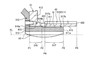
- FIG. 2 is an enlarged schematic view of a part of the transport device of FIG.
- FIG. 3 is an enlarged schematic view of a part of the transport device according to the modification.
- the present invention is not limited thereto.
- the constituent elements of the respective embodiments described below can be appropriately combined.
- some components may not be used.
- the direction along the rotation axis AX of the motor rotor 4 will be referred to as the “axial direction”, and the direction orthogonal to the rotation axis AX will be referred to as the “radial direction”.
- a direction toward one side in the axial direction is referred to as a “first direction D1”
- a direction toward the other side is referred to as a “second direction D2”.
- FIG. 1 is a cross-sectional view schematically showing an example of the overall configuration of a carrier device according to an embodiment.
- the transfer device 1 includes a housing 2, a motor stator 3 (stator), a motor rotor 4 (rotor), wheels 5, and an electromagnetic brake 6.
- the housing 2 includes a first wall 21 located on the first direction D1 side (left side in FIG. 1) that is one side in the axial direction and a second direction D2 side that is the opposite side to the first direction D1 side (FIG.
- the second wall 22 located on the right side of 1).
- the first wall 21 includes an axial wall portion 211 extending in the axial direction and a radial wall portion 212 extending in the radial direction.
- the axial wall portion 211 extends in a plane along the axial direction of the rotation axis AX.
- the radial wall portion 212 extends inward in the radial direction from the end portion 213 of the axial wall portion 211 on the first direction D1 side.
- the radial wall portion 212 extends in a plane shape along the radial direction.
- a screw hole (not shown) is provided in the axial wall portion 211 so as to penetrate in the radial direction (plate thickness direction).
- An object to be conveyed (not shown) is mounted on the upper surface of the axial wall portion 211. By fastening the bolt passing through the screw hole to the object to be conveyed, the object to be conveyed can be fixed to the upper surface of the axial wall portion 211.
- the second wall 22 is fixed to the end portion 214 of the axial wall portion 211 of the first wall 21 on the second direction D2 side.
- the second wall 22 includes a radial wall portion 221 extending in the radial direction, and an axial wall portion 223 extending in the first direction D1 from the radial end portion 222 (upper end portion shown in FIG. 1) of the radial wall portion 221. ,including.
- the axial wall portion 223 extends in a plane along the axial direction of the rotation axis AX.
- the radial wall portion 221 extends in a plane shape along the radial direction.
- the axial wall portion 223 of the second wall 22 and the end portion 214 of the axial wall portion 211 of the first wall 21 on the second direction D2 side are fixed via bolts BL.
- the motor stator 3 (stator) has a yoke portion 31, a stator stack 32, and a coil 33.
- a so-called outer rotor type drive motor is used as a drive source.
- the yoke portion 31 is a cylindrical member whose center is the rotation axis AX.
- the yoke portion 31 has a large diameter portion 311 arranged on the first direction D1 side, a small diameter portion 312 arranged on the second direction D2 side, and a connecting portion that connects the large diameter portion 311 and the small diameter portion 312. And 313.
- the large diameter portion 311 has a larger diameter than the small diameter portion 312.
- the connecting portion 313 is an annular member centered on the rotation axis AX and extends in the circumferential direction.
- a rotation detector 34 extending in the circumferential direction around the rotation axis AX is provided on the outer circumference of the small diameter portion 312.
- the rotation detector 34 detects the rotation state of the motor rotor 4.
- the rotation detector 34 is provided with a through hole 341 at the center in the radial direction.
- the outer periphery of the small diameter portion 312 is fitted in the through hole 341.
- the stator stack 32 is formed of a plurality of electromagnetic steel plates. That is, the stator stack 32 is formed by axially stacking a plurality of annular electromagnetic steel plates each having a through hole at the center in the radial direction.
- the stator stack 32 is formed of a magnetic material such as an electromagnetic steel plate.
- the coil 33 is a linear electric wire. The coil 33 is concentratedly wound around the stator stack 32.
- a wiring for supplying electric power from a power source is connected to the motor stator 3, and electric power is supplied to the coil through this wiring.
- the motor rotor 4 (rotor) has an annular member 41, a connecting wall 42, and a magnet 43.
- the annular member 41 has a circumferential wall portion 411 and a radial wall portion 412.
- the circumferential wall portion 411 extends along the circumferential direction about the rotation axis AX.
- the circumferential wall portion 411 is formed in a cylindrical shape.
- the radial wall portion 412 extends radially inward from the end portion 413 of the circumferential wall portion 411 on the first direction D1 side.
- the circumferential wall portion 411 and the radial wall portion 412 are integrated.
- the connecting wall 42 is provided with a through hole at the center in the radial direction.
- the radially outer end of the connecting wall 42 is fixed to the end 414 of the circumferential wall 411 on the second direction D2 side via a bolt BL. That is, the connecting wall 42 extends inward in the radial direction from the end portion of the circumferential wall portion 411 on the second direction D2 side.
- a permanent magnet such as an Nd-Fe-B system magnet can be used.
- the magnet 43 is formed in a cylindrical shape extending in the circumferential direction around the rotation axis AX.
- the magnet 43 is fixed inside the circumferential wall portion 411 of the annular member 41 in the radial direction.
- the stator stacks 32 are arranged to face each other inside the magnet 43 in the radial direction.
- the end 431 of the magnet 43 on the first direction D1 side and the end 321 of the stator stack 32 on the first direction D1 side are arranged side by side in the radial direction.
- the end 432 of the magnet 43 on the second direction D2 side and the end 322 of the stator stack 32 on the second direction D2 side are arranged side by side in the radial direction. That is, the axial length of the magnet 43 is equal to the axial length of the stator stack 32.
- the motor rotor 4 is rotatably supported via the yoke portion 31 and two bearings.
- the first bearing 10 is provided on the outer peripheral surface of the end of the yoke portion 31 on the first direction D1 side
- the second bearing 20 is provided on the end of the yoke portion 31 on the second direction D2 side.
- the first bearing 10 has an inner ring 11, an outer ring 12, and a rolling element 13.
- a groove is provided at an end of the yoke portion 31 on the first direction D1 side, and an inner ring is fitted in the groove.
- the thin plate 14 is provided on the first direction D1 side of the inner ring. The thin plate 14 is fixed to the yoke portion 31 by bolts BL. Thereby, the inner ring 11 is pressed and fixed to the yoke portion 31 by the thin plate 14.
- the outer ring 12 is fixed to the radially inner end of the radial wall 412.
- the annular member 41 is rotatably supported by the end of the yoke portion 31 on the first direction D1 side via the first bearing 10.
- the second bearing 20 has an inner ring 11, an outer ring 12, and a rolling element 13.
- the inner ring is fixed to the outer peripheral surface of the end of the yoke portion 31 on the second direction D2 side.
- the outer ring is fixed to the inner peripheral end of the connecting wall 42. Accordingly, the connecting wall 42 is rotatably supported by the end of the yoke portion 31 on the second direction D2 side via the second bearing 20.
- the motor rotor 4 is rotatably supported by the yoke portion 31 via the first bearing 10 and the second bearing 20 about the rotation axis AX.
- the central axis of the motor stator 3 coincides with the rotation axis AX of the motor rotor 4.
- the wheel 5 has a base 51 and a tire portion 52.
- the base 51 is substantially U-shaped in a cross section including the rotation axis AX.
- the base 51 has an annular wall portion 511 and a radial wall portion 512.
- the annular wall portion 511 extends annularly along the circumferential direction centered on the rotation axis AX.
- the annular wall portion 511 extends in the axial direction.
- the annular wall portion 511 is arranged radially outside the circumferential wall portion 411 of the annular member 41.
- the radial wall portion 512 is a disk-shaped member that extends inward in the radial direction from the end portion 513 of the annular wall portion 511 on the first direction D1 side.
- a concave portion 514 that is recessed in the second direction D2 is formed in the radial center portion of the radial wall portion 512.
- the recess 514 is formed in an annular shape around the rotation axis AX.
- the support shaft 40 extending in the first direction D1 is fixed to the recess 514 via a bolt BL.
- the inner diameter of the recess 514 is substantially the same as the outer diameter of the end of the support shaft 40 on the second direction D2 side. Therefore, the end portion of the support shaft 40 on the second direction D2 side is fixed to the radial wall portion 512 with the bolt BL while being fitted into the recess 514 without any gap.
- the support shaft 40 is rotatably supported by the radial wall portion 212 of the first wall 21 via the third bearing 30.
- the radially outer end of the radial wall portion 512 is fixed to the radial wall portion 412 of the annular member 41 via a bolt BL.
- the tire portion 52 is fixed to the outside of the annular wall portion 511 in the radial direction.
- the tire portion 52 is an elastic member such as rubber.
- the tire portion 52 is curved so as to expand radially outward as it approaches the central portion in the axial direction, as shown by the solid line in FIG.
- the electromagnetic brake 6 is a so-called non-excitation actuated brake, and includes a stator 61, an armature support member 62, and an armature plate 63.
- the stator 61 is a cylindrical member whose center is the rotation axis AX.
- a coil and a permanent magnet are integrally formed, and an end surface on the first direction D1 side (left side in FIG. 1) is a friction surface.
- the end portion of the stator 61 on the second direction D2 side (right side in FIG. 1) is fixed to the radial wall portion 212 of the first wall 21 via the bolt BL.
- the amateur support member 62 has a circumferential wall portion 621 and a radial wall portion 622.
- the circumferential wall portion 621 is attached to the outer peripheral surface of the end portion of the support shaft 40 on the first direction D1 side.
- a key groove is provided on the outer peripheral surface of the support shaft 40, and the key 623 is inserted into the key groove, so that the circumferential wall portion 621 is provided with a circumferential detent with respect to the support shaft 40. ing.
- a spacer 624 is provided between the end of the circumferential wall portion 621 on the second direction D2 side and the third bearing 30.
- the spacer 624 has a cylindrical shape and extends in the circumferential direction along the outer peripheral surface of the support shaft 40.
- the circumferential wall portion 621 is restrained from moving in the axial direction by the spacer 624. That is, the circumferential wall portion 621 is restricted from moving in the circumferential direction with respect to the support shaft 40 by the key 623, and restricted from moving in the axial direction by the spacer 624.
- the radial wall portion 622 expands radially outward from the end portion of the circumferential wall portion 621 on the first direction D1 side.
- a disk-shaped armature plate 63 is supported (connected) on the second direction D2 side of the radial wall portion 622 via a leaf spring (not shown).
- the armature plate 63 is arranged so as to face the friction surface of the stator 61.
- the electromagnetic brake 6 When a current is applied to a coil in the stator 61, the electromagnetic brake 6 magnetizes the stator 61, the generated attractive force overcomes the pressure of the leaf spring, and the armature plate 63 is separated from the friction surface of the stator 61 to be inoperative. It becomes the state of. In this state, rotation of the armature support member 62 connected to the armature plate 63, the support shaft 40, and the wheel 5 is allowed.
- the electromagnetic brake 6 when the current to the coil in the stator 61 is cut off, the magnetic attraction force of the stator 61 disappears, the armature plate 63 is pushed back by the force of the leaf spring, and the armature plate 63 is moved in the second direction D2. A braking force that stops the rotation of the armature plate 63 is generated by moving the armature plate 63 toward the friction surface of the stator 61. In this way, when the electromagnetic brake 6 is activated, the rotation of the armature support member 62 connected to the armature plate 63, the support shaft 40, and the wheel 5 is also braked.
- the electromagnetic brake 6 is not limited to the non-excitation type brake.
- FIG. 2 is an enlarged schematic view of a part of the transfer device of FIG.
- the radially inner surface 515 of the annular wall portion 511 has a contact area 516 and a separation area 517.
- the contact area 516 contacts the radially outer surface 415 of the circumferential wall portion 411 of the annular member 41.
- the contact area 516 extends from the end 516a on the first direction D1 side to the end 516b on the second direction D2 side.
- the separation region 517 extends from the end 517a on the first direction D1 side to the end 517b on the second direction D2 side.
- the separation region 517 is arranged radially outward from the radially outer surface 415 of the circumferential wall portion 411 of the annular member 41. That is, the separation area 517 is formed in a groove portion that is recessed radially outward from the contact area 516. A gap G along the radial direction is provided between the separated region 517 and the radially outer surface 415. In the cross section including the rotation axis AX, the radially outer surface 415 of the circumferential wall portion 411, the contact region 516, and the separation region 517 extend linearly along the axial direction. The separation area 517 is arranged radially outside the contact area 516.
- the position of the end 516a on the first direction D1 side in the contact area 516 is the first position P1
- the position of the end 516b on the second direction D2 side is the second position P2.
- the position of the end 511a on the second direction D2 side of the annular wall portion 511 is referred to as a third position P3.
- the end 431 of the magnet 43 on the first direction D1 side is the fourth position P4, and the position of the end 432 of the magnet 43 on the second direction D2 side is the fifth position P5.
- the fourth position P4 is located between the second position P2 and the third position P3 in the axial direction.
- the fourth position P4 is close to the second position P2 in the axial direction.
- the end 517a (the end in the axial direction) in the separated region 517 and the end 431 (the end in the axial direction) in the magnet 43 are arranged side by side in the radial direction.
- the third position P3 of the end 517b of the separated region 517 is located between the fourth position P4 and the fifth position P5. Therefore, in the cross section including the rotation axis AX, the magnet 43 is arranged radially inside the entire region along the axial direction of the separation region 517 with the annular wall portion 511 interposed therebetween.
- the magnet 43 is not arranged inside the contact area 516 in the radial direction with the annular wall portion 511 interposed therebetween.
- the radially inner side surface 515 of the annular wall portion 511 has the contact area 516 that comes into contact with the radially outer surface 415 of the circumferential wall portion 411 of the annular member 41, and the contact area 516.
- the magnet 43 is arranged radially inside the separation region 517 with the annular wall portion 511 interposed therebetween.
- the radially inner surface 515 of the annular wall portion 511 is separated from the radially outer surface 415 of the circumferential wall portion 411 toward the radially outer side. That is, in the separated area 517, a gap G is provided along the radial direction between the radial inner surface 515 of the annular wall portion 511 and the radial outer surface of the rotor. Therefore, when an impact force is input from the road surface FL to the annular wall portion 511 when the wheels 5 rotate and the transport device 1 travels, the impact force is mitigated in the separation area 517.
- the magnet 43 is arranged radially inside the separation region 517 with the annular wall portion 511 interposed therebetween. Therefore, the impact force transmitted to the magnet 43 is smaller than that in the case where the separated region 517 and the magnet 43 are displaced from each other in the axial direction. As described above, it is possible to prevent the impact force from being transmitted to the magnet 43 from the road surface FL via the wheels 5 during traveling.
- the magnet 43 is arranged radially inside the entire region along the axial direction of the separation region 517 with the annular wall portion 511 interposed therebetween.
- the wheel 5 can be moved from the road surface FL to the road 5 while traveling.
- the impact force transmitted to the magnet 43 via the magnet is further reduced.
- the motor rotor 4 (rotor) has a circumferential wall portion 411 extending along the circumferential direction about the rotation axis AX, and a radial wall portion 412 extending radially inward from the circumferential wall portion 411.
- the circumferential wall portion 411 and the radial wall portion 412 are integrated, the magnet 43 is fixed inside the circumferential wall portion 411 in the radial direction, and the wheel 5 is fixed to the radial wall portion 412.
- the radial wall portion 412 of the motor rotor 4 receives the impact force from the road surface FL. Since the circumferential wall portion 411 and the radial wall portion 412 are integrated, the rigidity is higher than in the case where the circumferential wall portion and the radial wall portion 412 are separate bodies. Therefore, even when the impact force from the road surface FL is input from the wheel 5 to the motor rotor 4, the impact force transmitted to the magnet 43 is further reduced.
- the radially outer surface 415 of the circumferential wall portion 411, the contact area 516, and the separation area 517 extend linearly along the axial direction.
- the separation area 517 is arranged radially outside the contact area 516.
- the radially outer surface 415 of the circumferential wall portion 411 extends linearly along the axial direction, and the outer peripheral surface of the motor rotor 4 (rotor) becomes a cylindrical surface having the same diameter.
- the surface has a simple shape. Therefore, the outer peripheral surface of the motor rotor 4 can be easily manufactured.
- the magnet 43 is fixed inside the circumferential wall portion 411 of the annular member 41 in the radial direction.
- the radially outer end portion of the radial wall portion 512 is fixed to the radial wall portion 412 of the annular member 41 via the bolt BL.
- the circumferential wall portion 411 and the radial wall portion 412 are integrated.
- the wheels 5 are separate from the motor rotor 4 (rotor), so it is easy to replace the wheels 5. Further, the wheel 5 is fixed to the annular member 41 via a contact area 516 which serves as a spigot portion.
- the embodiments have been described above, but the embodiments are not limited to the above contents.
- the gap G along the radial direction is provided between the separated region 517 and the radially outer surface 415.
- an elastic member 100 such as rubber may be arranged between the separated region 517 and the radially outer surface 415. In this case, the impact force transmitted from the road surface FL to the magnets 43 via the wheels 5 during traveling is absorbed by the elastic member 100 and becomes further smaller.
- Transport Device 100 Elastic Member 3 Motor Stator (Stator) 4 Motor rotor (rotor) 43 Magnet 411 Circumferential wall part 412 Radial wall part 5 Wheel 511 Annular wall part 516 Contact area 517 Separation area AX Rotation axis FL Road surface
Landscapes
- Engineering & Computer Science (AREA)
- Mechanical Engineering (AREA)
- Transportation (AREA)
- Chemical & Material Sciences (AREA)
- Combustion & Propulsion (AREA)
- Power Engineering (AREA)
- Connection Of Motors, Electrical Generators, Mechanical Devices, And The Like (AREA)
Abstract
搬送装置は、固定子と、前記固定子の径方向外側に配置され、回転軸を中心として回転可能であると共に、径方向内側に前記固定子に径方向で対向する磁石を有する回転子と、前記回転軸回りの周方向に延びて路面からの荷重が伝達可能な環状壁部を有すると共に、前記回転子の径方向外側に配置された車輪と、を備え、前記環状壁部における径方向内側面は、前記回転子の径方向外側面に当接する当接領域と、前記当接領域とは前記回転軸の軸方向にずれて位置し前記回転子の径方向外側面から径方向外側に向けて離隔される離隔領域と、を有し、前記磁石は、前記回転子を挟んで前記離隔領域の径方向内側に配置される。
Description
本開示は、搬送装置に関する。
工場内などに設けられ、駆動源であるダイレクトドライブモータを用いて車輪を回転駆動する搬送装置の一例が特許文献1に開示されている。この搬送装置においては、車輪(連結体)の径方向内側に円環状のロータ部が配置されている。車輪とロータ部とは、径方向で当接している。
従って、例えば段差など、搬送装置が走行する際に路面から車輪に衝撃力が入力された場合に、当該衝撃力がロータ部の内側に設けられた部材に伝達され、損傷を受ける可能性がある。
本開示は、磁石を有するモータを備えた搬送装置において、走行時に路面から車輪を介して衝撃力がロータ部の内側の部材に伝達することを抑制する搬送装置を提供することを目的とする。
本開示の一態様に係る搬送装置は、固定子と、前記固定子の径方向外側に配置され、回転軸を中心として回転可能であると共に、径方向内側に前記固定子に径方向で対向する磁石を有する回転子と、前記回転子の径方向外側に配置され前記回転軸回りの周方向に延びて路面からの荷重が伝達可能な環状壁部を有する車輪と、を備え、前記環状壁部における径方向内側面は、前記回転子の径方向外側面に当接する当接領域と、前記当接領域とは前記回転軸の軸方向にずれて位置し前記回転子の径方向外側面から径方向外側に向けて離隔される離隔領域と、を有し、前記磁石は、前記回転子を挟んで前記離隔領域の径方向内側に配置される。
離隔領域においては、環状壁部における径方向内側面が回転子の径方向外側面から径方向外側に向けて離隔されている。即ち、離隔領域においては、環状壁部における径方向内側面と回転子の径方向外側面との間には、径方向に沿って間隙が設けられている。従って、車輪が回転して搬送装置が走行する際に、路面から環状壁部に衝撃力が入力された場合に、離隔領域においては、当該衝撃力が緩和される。ここで、磁石は、回転子を挟んで離隔領域の径方向内側に配置される。よって、離隔領域と磁石とが軸方向でずれている場合よりも、磁石に伝達される衝撃力が小さくなる。以上より、走行時に路面から車輪を介して衝撃力が磁石に伝達することを抑制することができる。
搬送装置の望ましい態様では、前記磁石は、前記回転子を挟んで前記離隔領域の前記軸方向に沿った全領域の径方向内側に配置されることが好ましい。
これによれば、前記磁石が前記回転子を挟んで前記離隔領域の軸方向の一部の領域の径方向内側に配置される場合と比較して、走行時に路面から車輪を介して磁石に伝達する衝撃力が更に小さくなる。
搬送装置の望ましい態様では、前記回転子は、前記回転軸を中心として周方向に沿って延びる周方向壁部と、前記周方向壁部から径方向内側に向けて延びる径方向壁部とを有し、前記周方向壁部と前記径方向壁部とは一体であり、前記磁石は前記周方向壁部の径方向内側に固定され、前記車輪は前記径方向壁部に固定されることが好ましい。
車輪は径方向壁部に固定されるため、路面からの衝撃力を回転子の径方向壁部で受ける。周方向壁部と径方向壁部とは一体であるため、周方向壁部と径方向壁部とが別体の場合よりも剛性が高い。従って、路面からの衝撃力が車輪から回転子に入力された場合でも、磁石に伝達される衝撃力が更に小さくなる。
搬送装置の望ましい態様では、前記回転子の前記径方向外側面と前記離隔領域との間に弾性部材を設けることが好ましい。
これによれば、走行時に路面から車輪を介して磁石に伝達する衝撃力が弾性部材によって吸収されて更に小さくなる。
搬送装置の望ましい態様では、前記回転軸を含む断面において、前記回転子の前記径方向外側面と、前記当接領域と、前記離隔領域とは、それぞれ軸方向に沿って直線状に延びることが好ましい。
これによれば、回転子の径方向外側面が軸方向に沿って直線状に延び、回転子の外周面が同一径の円筒面になるため、回転子の外周面が単純な形状となる。従って、回転子の外周面の製作が容易になる。
本発明の態様によれば、走行時に路面から車輪を介して衝撃力が磁石に伝達することを抑制する搬送装置を提供することができる。
以下、本発明に係る実施形態について図面を参照しながら説明するが、本発明はこれに限定されない。以下で説明する各実施形態の構成要素は、適宜組み合わせることができる。また、一部の構成要素を用いない場合もある。なお、以下において、モータロータ4の回転軸AXに沿った方向を「軸方向」と称し、回転軸AXに直交する方向を「径方向」と称する。また、軸方向の一方側に向かう方向を「第1方向D1」とし、他方側に向かう方向を「第2方向D2」と称する。
図1は、実施形態に係る搬送装置の全体構成の一例を概略的に示す断面図である。
図1に示すように、搬送装置1は、筐体2と、モータステータ3(固定子)と、モータロータ4(回転子)と、車輪5と、電磁ブレーキ6と、を備える。
筐体2は、軸方向の一方側である第1方向D1側(図1の左側)に位置する第1壁21と、第1方向D1側の反対方向側である第2方向D2側(図1の右側)に位置する第2壁22と、を有する。
第1壁21は、軸方向に沿って延びる軸方向壁部211と、径方向に沿って延びる径方向壁部212と、を含む。軸方向壁部211は、回転軸AXの軸方向に沿って平面状に延びている。径方向壁部212は、軸方向壁部211における第1方向D1側の端部213から径方向内側に向けて延びている。径方向壁部212は、径方向に沿って平面状に延びている。なお、軸方向壁部211には、図示しないねじ穴が径方向(板厚方向)に貫通して設けられている。軸方向壁部211の上面に搬送対象物(図示せず)が搭載される。前記ねじ穴を通したボルトを搬送対象物に締結することにより、当該搬送対象物を軸方向壁部211の上面に固定することができる。
第2壁22は、第1壁21の軸方向壁部211における第2方向D2側の端部214に固定されている。第2壁22は、径方向に延びる径方向壁部221と、径方向壁部221における径方向端部222(図1に示す上側端部)から第1方向D1に延びる軸方向壁部223と、を含む。軸方向壁部223は、回転軸AXの軸方向に沿って平面状に延びている。径方向壁部221は、径方向に沿って平面状に延びている。第2壁22の軸方向壁部223と、第1壁21の軸方向壁部211における第2方向D2側の端部214とは、ボルトBLを介して固定されている。
モータステータ3(固定子)は、ヨーク部31と、ステータスタック32と、コイル33と、を有する。なお、本実施形態では、いわゆるアウターロータ型ドライブモータを駆動源としている。
ヨーク部31は、回転軸AXを中心とする円筒状の部材である。ヨーク部31は、第1方向D1側に配置された大径部311と、第2方向D2側に配置された小径部312と、これらの大径部311と小径部312とを連結する連結部313と、を有する。
大径部311は、小径部312よりも径が大きい。連結部313は、回転軸AXを中心とする環状の部材であり、周方向に延びている。小径部312の外周には、回転軸AXを中心として周方向に延びる回転検出器34が設けられている。回転検出器34は、モータロータ4の回転状態を検出する。回転検出器34には、径方向中央部に貫通孔341が設けられている。貫通孔341に小径部312の外周が嵌合されている。
ステータスタック32は、複数の電磁鋼板で形成される。即ち、径方向中央部に貫通孔が設けられた環状の電磁鋼板が軸方向に複数積層されて、ステータスタック32が形成される。ステータスタック32は、電磁鋼板などの磁性材料で形成される。コイル33は、線状の電線である。コイル33は、ステータスタック32に集中巻きされる。図示しないが、モータステータ3には、電源からの電力を供給するための配線が接続されており、この配線を通じてコイルに対して電力が供給される。
モータロータ4(回転子)は、環状部材41と、連結壁42と、磁石43と、を有する。
環状部材41は、周方向壁部411と、径方向壁部412と、を有する。周方向壁部411は、回転軸AXを中心とする周方向に沿って延びる。周方向壁部411は、円筒状に形成されている。
径方向壁部412は、周方向壁部411における第1方向D1側の端部413から径方向内側に向けて延びる。周方向壁部411と径方向壁部412とは一体である。連結壁42には、径方向中央部に貫通孔が設けられている。連結壁42における径方向外側の端部は、周方向壁部411における第2方向D2側の端部414とボルトBLを介して固定されている。即ち、連結壁42は、周方向壁部411における第2方向D2側の端部から径方向内側に向けて延びる。
磁石43は、例えばNd-Fe-B系磁石等の永久磁石を用いることができる。磁石43は、回転軸AXを中心として周方向に延びる円筒状に形成されている。環状部材41の周方向壁部411の径方向内側に磁石43が固定されている。磁石43の径方向内側には、ステータスタック32が対向して配置されている。
磁石43における第1方向D1側の端431と、ステータスタック32における第1方向D1側の端321とは径方向に並んで配置されている。磁石43における第2方向D2側の端432と、ステータスタック32における第2方向D2側の端322とは径方向に並んで配置されている。即ち、磁石43の軸方向長さは、ステータスタック32の軸方向長さと同等である。
ここで、モータロータ4は、ヨーク部31と2つの軸受を介して回転可能に支持されている。ヨーク部31における第1方向D1側の端部の外周面には、第1軸受10が設けられ、第2方向D2側の端部には、第2軸受20が設けられている。
第1軸受10は、内側輪11と、外側輪12と、転動体13と、を有する。ヨーク部31における第1方向D1側の端部には、溝が設けられ、溝に内側輪が嵌合されている。内側輪の第1方向D1側には、薄板14が設けられる。薄板14は、ボルトBLによってヨーク部31に固定されている。これにより、内側輪11は、薄板14によってヨーク部31に押さえ付けられて固定されている。
外側輪12は、径方向壁部412における径方向内側の端部に固定されている。これにより、環状部材41は、第1軸受10を介して、ヨーク部31における第1方向D1側の端部に回転可能に支持されている。
また、第2軸受20は、内側輪11と、外側輪12と、転動体13と、を有する。内側輪は、ヨーク部31における第2方向D2側の端部の外周面に固定される。外側輪は、連結壁42の内周側の端部に固定されている。これにより、連結壁42は、第2軸受20を介して、ヨーク部31における第2方向D2側の端部に回転可能に支持されている。
以上より、モータロータ4は、ヨーク部31に対して第1軸受10及び第2軸受20を介して、回転軸AXを中心として回転可能に支持されている。モータステータ3の中心軸は、モータロータ4の回転軸AXと一致する。
車輪5は、ベース51と、タイヤ部52と、を有する。
ベース51は、回転軸AXを含む断面において、略U字状である。ベース51は、環状壁部511と、径方向壁部512と、を有する。環状壁部511は、回転軸AXを中心とする周方向に沿って環状に延びる。なお、回転軸AXを含む断面において、環状壁部511は軸方向に延びる。
環状壁部511は、環状部材41の周方向壁部411の径方向外側に配置される。径方向壁部512は、環状壁部511における第1方向D1側の端部513から径方向内側に向けて延びる円盤状の部材である。径方向壁部512における径方向中央部には、第2方向D2に向けて凹む凹部514が形成されている。
凹部514は、回転軸AXを中心として環状に形成されている。凹部514には、第1方向D1に向けて延びる支持軸40がボルトBLを介して固定されている。凹部514の内径は、支持軸40における第2方向D2側の端部の外径と略同一である。従って、支持軸40における第2方向D2側の端部は、凹部514に隙間なく嵌合された状態でボルトBLで径方向壁部512に固定されている。
支持軸40は、第3軸受30を介して第1壁21の径方向壁部212に回転可能に支持されている。また、径方向壁部512における径方向外側の端部は、ボルトBLを介して環状部材41の径方向壁部412に固定されている。
タイヤ部52は、環状壁部511の径方向外側に固定されている。タイヤ部52は、ゴムなどの弾性部材である。タイヤ部52は、路面FLからの荷重を受けていないときは、図1の実線で示すように、軸方向中央部に近づくに従って径方向外側に膨らむように湾曲している。
しかし、タイヤ部52が路面FL上を走行すると、路面FLから径方向内側に向けてタイヤ部52に荷重が入力される。このとき、図2の二点鎖線に示すように、タイヤ部52の径方向の厚さが軸方向に沿って略均一になる。従って、路面FLからタイヤ部52を介して環状壁部511に軸方向に沿って略均一の荷重が入力される。
電磁ブレーキ6は、いわゆる無励磁作動形のブレーキであり、ステータ61と、アマチュア支持部材62と、アマチュア板63と、を含む。ステータ61は、回転軸AXを中心とする円筒状の部材である。ステータ61は、コイルと永久磁石とが一体になって構成されており、第1方向D1側(図1の左側)の端面が摩擦面になっている。ステータ61における第2方向D2側(図1の右側)の端部は、ボルトBLを介して第1壁21の径方向壁部212に固定されている。
アマチュア支持部材62は、周方向壁部621と、径方向壁部622とを有する。周方向壁部621は、支持軸40における第1方向D1側の端部の外周面に取り付けられている。詳細には、支持軸40の外周面にキー溝が設けられ、このキー溝にキー623が挿入されることにより、周方向壁部621は支持軸40に対して周方向の回り止めが施されている。
また、周方向壁部621における第2方向D2側の端縁と、第3軸受30との間には、スペーサ624が設けられている。スペーサ624は、円筒状の形状を有し、支持軸40の外周面に沿って周方向に延びている。周方向壁部621は、スペーサ624によって軸方向の移動が拘束されている。即ち、周方向壁部621は、キー623によって支持軸40に対する周方向の移動が制限され、スペーサ624によって軸方向の移動が制限されている。
径方向壁部622は、周方向壁部621における第1方向D1側の端部から径方向外側に向けて広がっている。径方向壁部622の第2方向D2側に、図示しない板バネを介して円板状のアマチュア板63が支持(連結)されている。アマチュア板63は、ステータ61の摩擦面と対向して配置されている。
次いで、電磁ブレーキ6の作動について説明する。
電磁ブレーキ6は、ステータ61におけるコイルに電流が印加されると、ステータ61が磁化され、発生した吸引力が板バネの圧力に打ち勝ち、アマチュア板63がステータ61の摩擦面から離隔されて非作動の状態となる。この状態では、アマチュア板63に連結されたアマチュア支持部材62、支持軸40及び車輪5の回転が許容される。
電磁ブレーキ6は、ステータ61におけるコイルに電流が印加されると、ステータ61が磁化され、発生した吸引力が板バネの圧力に打ち勝ち、アマチュア板63がステータ61の摩擦面から離隔されて非作動の状態となる。この状態では、アマチュア板63に連結されたアマチュア支持部材62、支持軸40及び車輪5の回転が許容される。
また、電磁ブレーキ6は、ステータ61におけるコイルへの電流が遮断されると、ステータ61の磁気吸引力は消滅し、アマチュア板63が板バネの力により押し戻され、アマチュア板63が第2方向D2に向けて移動してステータ61の摩擦面に当接し、アマチュア板63の回転を止める制動力が発生する。このように、電磁ブレーキ6が作動状態になると、アマチュア板63に連結されたアマチュア支持部材62、支持軸40及び車輪5の回転も制動される。なお、電磁ブレーキ6は、無励磁形ブレーキに限定されるものではない。
図2は、図1の搬送装置の一部を拡大した模式図である。環状壁部511における径方向内側面515は、当接領域516と、離隔領域517と、を有する。当接領域516は、環状部材41の周方向壁部411における径方向外側面415に当接する。当接領域516は、第1方向D1側の端516aから第2方向D2側の端516bまで延びる。離隔領域517は、第1方向D1側の端517aから第2方向D2側の端517bまで延びる。
離隔領域517は、環状部材41の周方向壁部411における径方向外側面415から径方向外側に離隔して配置される。即ち、離隔領域517は、当接領域516よりも径方向外側に凹んだ溝部に形成されている。離隔領域517と径方向外側面415との間には、径方向に沿った間隙Gが設けられる。回転軸AXを含む断面において、周方向壁部411における径方向外側面415と、当接領域516と、離隔領域517とは、軸方向に沿って直線状に延びる。離隔領域517は、当接領域516よりも径方向外側に配置される。
ここで、当接領域516における第1方向D1側の端516aの位置を第1位置P1とし、第2方向D2側の端516bの位置を第2位置P2とする。環状壁部511における第2方向D2側の端511aの位置を第3位置P3とする。また、磁石43における第1方向D1側の端431を第4位置P4とし、第2方向D2側の端432の位置を第5位置P5とする。第4位置P4は、軸方向において、第2位置P2と第3位置P3との間に位置している。
軸方向において、第4位置P4が第2位置P2に近接していることが好ましい。離隔領域517における端517a(軸方向の端)と、磁石43における端431(軸方向の端)とは、径方向に並んで配置されている。離隔領域517の端517bの第3位置P3は、第4位置P4と第5位置P5との間に位置している。従って、回転軸AXを含む断面において、磁石43は、環状壁部511を挟んで離隔領域517の軸方向に沿った全領域の径方向内側に配置される。なお、磁石43は、環状壁部511を挟んで当接領域516の径方向内側には、配置されない。
以上説明した搬送装置1においては、環状壁部511における径方向内側面515は、環状部材41の周方向壁部411における径方向外側面415に当接する当接領域516と、当接領域516とは軸方向にずれて位置し径方向外側面415から径方向外側に向けて離隔される離隔領域517と、を有する。磁石43は、環状壁部511を挟んで離隔領域517の径方向内側に配置される。
離隔領域517においては、環状壁部511における径方向内側面515が周方向壁部411における径方向外側面415から径方向外側に向けて離隔されている。即ち、離隔領域517においては、環状壁部511における径方向内側面515と回転子の径方向外側面との間には、径方向に沿って間隙Gが設けられている。従って、車輪5が回転して搬送装置1が走行する際に、路面FLから環状壁部511に衝撃力が入力された場合に、離隔領域517においては、当該衝撃力が緩和される。
ここで、磁石43は、環状壁部511を挟んで離隔領域517の径方向内側に配置される。よって、離隔領域517と磁石43とが軸方向にずれている場合よりも、磁石43に伝達される衝撃力が小さくなる。以上より、走行時に路面FLから車輪5を介して衝撃力が磁石43に伝達することを抑制することができる。
回転軸AXを含む断面において、磁石43は、環状壁部511を挟んで離隔領域517の軸方向に沿った全領域の径方向内側に配置される。
これによれば、磁石43が、環状壁部511を挟んで離隔領域517の軸方向に沿った一部の領域の径方向内側に配置される場合と比較して、走行時に路面FLから車輪5を介して磁石43に伝達する衝撃力が更に小さくなる。
モータロータ4(回転子)は、回転軸AXを中心として周方向に沿って延びる周方向壁部411と、周方向壁部411から径方向内側に向けて延びる径方向壁部412とを有し、周方向壁部411と径方向壁部412とは一体であり、磁石43は周方向壁部411の径方向内側に固定され、車輪5は径方向壁部412に固定される。
車輪5は径方向壁部412に固定されるため、路面FLからの衝撃力をモータロータ4の径方向壁部412で受ける。周方向壁部411と径方向壁部412とは一体であるため、周方向壁部と径方向壁部412とが別体の場合よりも剛性が高い。従って、路面FLからの衝撃力が車輪5からモータロータ4に入力された場合でも、磁石43に伝達される衝撃力が更に小さくなる。
回転軸AXを含む断面において、周方向壁部411における径方向外側面415と、当接領域516と、離隔領域517とは、軸方向に沿って直線状に延びる。離隔領域517は、当接領域516よりも径方向外側に配置される。
これによれば、周方向壁部411における径方向外側面415が軸方向に沿って直線状に延び、モータロータ4(回転子)の外周面が同一径の円筒面になるため、モータロータ4の外周面が単純な形状となる。従って、モータロータ4の外周面の製作が容易になる。
また、環状部材41の周方向壁部411の径方向内側に磁石43が固定されている。径方向壁部512における径方向外側の端部は、ボルトBLを介して環状部材41の径方向壁部412に固定されている。周方向壁部411と径方向壁部412とは一体である。
なお、車輪5は、モータロータ4(回転子)とは別体になっているため、車輪5の交換が容易である。また、車輪5は、インロー部となる当接領域516を介して環状部材41に固定されている。
以上、実施形態を説明したが、前述した内容により実施形態が限定されるものではない。例えば、実施形態では、離隔領域517と径方向外側面415との間には、径方向に沿った間隙Gを設けた。しかし、図3の変形例に示すように、離隔領域517と径方向外側面415との間に、ゴムなどの弾性部材100を配置させてもよい。この場合、走行時に路面FLから車輪5を介して磁石43に伝達する衝撃力が弾性部材100によって吸収されて更に小さくなる。
1 搬送装置
100 弾性部材
3 モータステータ(固定子)
4 モータロータ(回転子)
43 磁石
411 周方向壁部
412 径方向壁部
5 車輪
511 環状壁部
516 当接領域
517 離隔領域
AX 回転軸
FL 路面
100 弾性部材
3 モータステータ(固定子)
4 モータロータ(回転子)
43 磁石
411 周方向壁部
412 径方向壁部
5 車輪
511 環状壁部
516 当接領域
517 離隔領域
AX 回転軸
FL 路面
Claims (5)
- 固定子と、
前記固定子の径方向外側に配置され、回転軸を中心として回転可能であると共に、径方向内側に前記固定子に径方向で対向する磁石を有する回転子と、
前記回転子の径方向外側に配置され前記回転軸回りの周方向に延びて路面からの荷重が伝達可能な環状壁部を有する車輪と、
を備え、
前記環状壁部における径方向内側面は、前記回転子の径方向外側面に当接する当接領域と、前記当接領域とは前記回転軸の軸方向にずれて位置し前記回転子の径方向外側面から径方向外側に向けて離隔される離隔領域と、を有し、
前記磁石は、前記回転子を挟んで前記離隔領域の径方向内側に配置される、
搬送装置。 - 前記磁石は、前記回転子を挟んで前記離隔領域の前記軸方向に沿った全領域の径方向内側に配置される、
請求項1に記載の搬送装置。 - 前記回転子は、前記回転軸を中心として周方向に沿って延びる周方向壁部と、前記周方向壁部から径方向内側に向けて延びる径方向壁部とを有し、前記周方向壁部と前記径方向壁部とは一体であり、
前記磁石は前記周方向壁部の径方向内側に固定され、前記車輪は前記径方向壁部に固定される、
請求項1又は2に記載の搬送装置。 - 前記回転子の前記径方向外側面と前記離隔領域との間に弾性部材を設けた、
請求項1から3のいずれか1項に記載の搬送装置。 - 前記回転軸を含む断面において、
前記回転子の前記径方向外側面と、前記当接領域と、前記離隔領域とは、それぞれ軸方向に沿って直線状に延びる、
請求項1から4のいずれか1項に記載の搬送装置。
Applications Claiming Priority (2)
| Application Number | Priority Date | Filing Date | Title |
|---|---|---|---|
| JP2018222170 | 2018-11-28 | ||
| JP2018-222170 | 2018-11-28 |
Publications (1)
| Publication Number | Publication Date |
|---|---|
| WO2020111095A1 true WO2020111095A1 (ja) | 2020-06-04 |
Family
ID=70853814
Family Applications (1)
| Application Number | Title | Priority Date | Filing Date |
|---|---|---|---|
| PCT/JP2019/046300 Ceased WO2020111095A1 (ja) | 2018-11-28 | 2019-11-27 | 搬送装置 |
Country Status (1)
| Country | Link |
|---|---|
| WO (1) | WO2020111095A1 (ja) |
Citations (2)
| Publication number | Priority date | Publication date | Assignee | Title |
|---|---|---|---|---|
| JPH05191957A (ja) * | 1992-01-13 | 1993-07-30 | Max:Kk | 電気自動車用の駆動輪構造 |
| JP2012176664A (ja) * | 2011-02-25 | 2012-09-13 | Topy Industries Ltd | モータ内蔵型ホイール装置及びその組立方法並びに組立・分解装置 |
-
2019
- 2019-11-27 WO PCT/JP2019/046300 patent/WO2020111095A1/ja not_active Ceased
Patent Citations (2)
| Publication number | Priority date | Publication date | Assignee | Title |
|---|---|---|---|---|
| JPH05191957A (ja) * | 1992-01-13 | 1993-07-30 | Max:Kk | 電気自動車用の駆動輪構造 |
| JP2012176664A (ja) * | 2011-02-25 | 2012-09-13 | Topy Industries Ltd | モータ内蔵型ホイール装置及びその組立方法並びに組立・分解装置 |
Similar Documents
| Publication | Publication Date | Title |
|---|---|---|
| US10498182B2 (en) | Electric machine having mechanical field weakening and including a fail-safe actuator system | |
| US8123012B2 (en) | Rotational coupling device with wear compensation structure | |
| US9166457B2 (en) | Rotating apparatus having rotating electrical machine and reduction device with common rotating shaft | |
| CN105830309B (zh) | 具有相应至少两个用于固定永磁体的夹紧凸耳的电机 | |
| JP5573217B2 (ja) | 電磁ブレーキ | |
| US7944102B2 (en) | Electrical machine with magnetic brake directly on the rotor | |
| CN102629797A (zh) | 旋转电机和旋转设备 | |
| US5971121A (en) | Mag stop clutch with center pole | |
| TWI667870B (zh) | Non-excited drive brake and motor | |
| US9906088B2 (en) | Rotor-holding structure of rotating electrical machine for hybrid vehicle | |
| US10944309B2 (en) | Electric motor device | |
| US20190123616A1 (en) | Electric linear actuator | |
| JP2015036568A (ja) | 電磁ブレーキ | |
| WO2020111095A1 (ja) | 搬送装置 | |
| JP2021141708A (ja) | 磁気減速機およびこの磁気減速機を備えた電機装置 | |
| JPH076532U (ja) | 電磁クラッチ・ブレーキ | |
| JPH0725469Y2 (ja) | 電磁ブレーキ | |
| JP7694441B2 (ja) | 電磁ブレーキ装置 | |
| JPH0725470Y2 (ja) | 電磁ブレーキ | |
| JP2018091428A (ja) | 電磁ブレーキ | |
| KR200375863Y1 (ko) | 모터 브레이크 장치 | |
| JP2022083685A (ja) | クラッチ装置 | |
| WO2024058222A1 (ja) | 搬送ローラ | |
| JP2025116441A (ja) | ラジアルギャップ型モータ | |
| JP2015165163A (ja) | 無励磁作動型電磁ブレーキ |
Legal Events
| Date | Code | Title | Description |
|---|---|---|---|
| 121 | Ep: the epo has been informed by wipo that ep was designated in this application |
Ref document number: 19890699 Country of ref document: EP Kind code of ref document: A1 |
|
| NENP | Non-entry into the national phase |
Ref country code: DE |
|
| 122 | Ep: pct application non-entry in european phase |
Ref document number: 19890699 Country of ref document: EP Kind code of ref document: A1 |
|
| NENP | Non-entry into the national phase |
Ref country code: JP |