WO2020111052A1 - レーダ装置 - Google Patents
レーダ装置 Download PDFInfo
- Publication number
- WO2020111052A1 WO2020111052A1 PCT/JP2019/046134 JP2019046134W WO2020111052A1 WO 2020111052 A1 WO2020111052 A1 WO 2020111052A1 JP 2019046134 W JP2019046134 W JP 2019046134W WO 2020111052 A1 WO2020111052 A1 WO 2020111052A1
- Authority
- WO
- WIPO (PCT)
- Prior art keywords
- hypothesis
- accuracy
- distribution
- speed
- cycle
- Prior art date
- Legal status (The legal status is an assumption and is not a legal conclusion. Google has not performed a legal analysis and makes no representation as to the accuracy of the status listed.)
- Ceased
Links
Images







Classifications
-
- G—PHYSICS
- G01—MEASURING; TESTING
- G01S—RADIO DIRECTION-FINDING; RADIO NAVIGATION; DETERMINING DISTANCE OR VELOCITY BY USE OF RADIO WAVES; LOCATING OR PRESENCE-DETECTING BY USE OF THE REFLECTION OR RERADIATION OF RADIO WAVES; ANALOGOUS ARRANGEMENTS USING OTHER WAVES
- G01S13/00—Systems using the reflection or reradiation of radio waves, e.g. radar systems; Analogous systems using reflection or reradiation of waves whose nature or wavelength is irrelevant or unspecified
- G01S13/02—Systems using reflection of radio waves, e.g. primary radar systems; Analogous systems
- G01S13/06—Systems determining position data of a target
- G01S13/08—Systems for measuring distance only
- G01S13/10—Systems for measuring distance only using transmission of interrupted, pulse modulated waves
- G01S13/26—Systems for measuring distance only using transmission of interrupted, pulse modulated waves wherein the transmitted pulses use a frequency- or phase-modulated carrier wave
- G01S13/28—Systems for measuring distance only using transmission of interrupted, pulse modulated waves wherein the transmitted pulses use a frequency- or phase-modulated carrier wave with time compression of received pulses
-
- G—PHYSICS
- G01—MEASURING; TESTING
- G01S—RADIO DIRECTION-FINDING; RADIO NAVIGATION; DETERMINING DISTANCE OR VELOCITY BY USE OF RADIO WAVES; LOCATING OR PRESENCE-DETECTING BY USE OF THE REFLECTION OR RERADIATION OF RADIO WAVES; ANALOGOUS ARRANGEMENTS USING OTHER WAVES
- G01S13/00—Systems using the reflection or reradiation of radio waves, e.g. radar systems; Analogous systems using reflection or reradiation of waves whose nature or wavelength is irrelevant or unspecified
- G01S13/02—Systems using reflection of radio waves, e.g. primary radar systems; Analogous systems
- G01S13/06—Systems determining position data of a target
- G01S13/08—Systems for measuring distance only
- G01S13/10—Systems for measuring distance only using transmission of interrupted, pulse modulated waves
- G01S13/26—Systems for measuring distance only using transmission of interrupted, pulse modulated waves wherein the transmitted pulses use a frequency- or phase-modulated carrier wave
- G01S13/28—Systems for measuring distance only using transmission of interrupted, pulse modulated waves wherein the transmitted pulses use a frequency- or phase-modulated carrier wave with time compression of received pulses
- G01S13/284—Systems for measuring distance only using transmission of interrupted, pulse modulated waves wherein the transmitted pulses use a frequency- or phase-modulated carrier wave with time compression of received pulses using coded pulses
- G01S13/288—Systems for measuring distance only using transmission of interrupted, pulse modulated waves wherein the transmitted pulses use a frequency- or phase-modulated carrier wave with time compression of received pulses using coded pulses phase modulated
-
- G—PHYSICS
- G01—MEASURING; TESTING
- G01S—RADIO DIRECTION-FINDING; RADIO NAVIGATION; DETERMINING DISTANCE OR VELOCITY BY USE OF RADIO WAVES; LOCATING OR PRESENCE-DETECTING BY USE OF THE REFLECTION OR RERADIATION OF RADIO WAVES; ANALOGOUS ARRANGEMENTS USING OTHER WAVES
- G01S13/00—Systems using the reflection or reradiation of radio waves, e.g. radar systems; Analogous systems using reflection or reradiation of waves whose nature or wavelength is irrelevant or unspecified
- G01S13/02—Systems using reflection of radio waves, e.g. primary radar systems; Analogous systems
- G01S13/06—Systems determining position data of a target
- G01S13/42—Simultaneous measurement of distance and other co-ordinates
-
- G—PHYSICS
- G01—MEASURING; TESTING
- G01S—RADIO DIRECTION-FINDING; RADIO NAVIGATION; DETERMINING DISTANCE OR VELOCITY BY USE OF RADIO WAVES; LOCATING OR PRESENCE-DETECTING BY USE OF THE REFLECTION OR RERADIATION OF RADIO WAVES; ANALOGOUS ARRANGEMENTS USING OTHER WAVES
- G01S13/00—Systems using the reflection or reradiation of radio waves, e.g. radar systems; Analogous systems using reflection or reradiation of waves whose nature or wavelength is irrelevant or unspecified
- G01S13/02—Systems using reflection of radio waves, e.g. primary radar systems; Analogous systems
- G01S13/50—Systems of measurement based on relative movement of target
- G01S13/58—Velocity or trajectory determination systems; Sense-of-movement determination systems
- G01S13/583—Velocity or trajectory determination systems; Sense-of-movement determination systems using transmission of continuous unmodulated waves, amplitude-, frequency-, or phase-modulated waves and based upon the Doppler effect resulting from movement of targets
- G01S13/584—Velocity or trajectory determination systems; Sense-of-movement determination systems using transmission of continuous unmodulated waves, amplitude-, frequency-, or phase-modulated waves and based upon the Doppler effect resulting from movement of targets adapted for simultaneous range and velocity measurements
-
- G—PHYSICS
- G01—MEASURING; TESTING
- G01S—RADIO DIRECTION-FINDING; RADIO NAVIGATION; DETERMINING DISTANCE OR VELOCITY BY USE OF RADIO WAVES; LOCATING OR PRESENCE-DETECTING BY USE OF THE REFLECTION OR RERADIATION OF RADIO WAVES; ANALOGOUS ARRANGEMENTS USING OTHER WAVES
- G01S13/00—Systems using the reflection or reradiation of radio waves, e.g. radar systems; Analogous systems using reflection or reradiation of waves whose nature or wavelength is irrelevant or unspecified
- G01S13/88—Radar or analogous systems specially adapted for specific applications
- G01S13/93—Radar or analogous systems specially adapted for specific applications for anti-collision purposes
- G01S13/931—Radar or analogous systems specially adapted for specific applications for anti-collision purposes of land vehicles
Definitions
- the present disclosure relates to a radar device that detects an object that reflects a radar wave by transmitting and receiving a radar wave.
- Patent Document 1 describes a radar device that calculates a relative velocity (hereinafter, target velocity) of an object by receiving a radar wave that is repeatedly transmitted through an antenna at a predetermined repetition cycle and reflected by the object. ing.
- the observable speed range of the observation speed is ⁇ /, where ⁇ is the wavelength of the radar wave. It is from 4Tp to + ⁇ /4Tp.
- stagger processing that changes the observable speed range for each cycle is generally used by changing the repetition cycle for each cycle.
- this stagger processing it is necessary to observe the change in the observation speed over several cycles and solve the aliasing ambiguity of the target speed.
- the return ambiguity has been solved by simply setting a plurality of target velocity assumptions over several cycles and setting the target velocity corresponding to the assumption that tracking continues to be continuous for several cycles as the true target velocity.
- the present disclosure improves the detection accuracy of the speed of an object.
- One aspect of the present disclosure is a radar device including a transmission unit, a repetition cycle setting unit, an object detection unit, and a hypothesis selection unit.
- the transmitter uses a preset measurement cycle as one cycle, and a radar wave whose frequency changes with time each time the measurement cycle elapses. It is configured to repeatedly send the number of returns.
- the repeat cycle setting unit is configured to change the repeat cycle every time the measurement cycle elapses.
- the object detection unit is configured to detect the radar wave reflected by the object and at least detect the relative speed with respect to the reflected object that is the object that reflected the radar wave as the observation speed.
- the hypothesis selecting unit is configured to perform the first distribution based on the velocity accuracy posterior distribution for each of the first hypothesis, the second hypothesis, and the third hypothesis, which is calculated by the velocity accuracy prior distribution and the detection result of the observation velocity for the number of distribution calculations. It is configured to select one of the hypothesis, the second hypothesis, and the third hypothesis.
- the first hypothesis is a hypothesis that the observation speed is the detection result of the return of the relative speed larger than the upper limit of the observable speed range set based on the repetition period.
- the second hypothesis is a hypothesis that the observed velocity is a detection result when the relative velocity has no aliasing.
- the third hypothesis is a hypothesis that the observation speed is a detection result by folding back of the relative speed smaller than the lower limit of the observable speed range.
- Speed accuracy is the accuracy of relative speed.
- the speed accuracy prior distribution is a prior distribution regarding speed accuracy.
- the velocity accuracy posterior distribution is a posterior distribution regarding the velocity accuracy after a preset number of cycles of distribution calculation have elapsed.
- the radar device of the present disclosure configured as above has the velocity accuracy posterior distribution calculated based on the first hypothesis, the velocity accuracy posterior distribution calculated based on the second hypothesis, and the calculation based on the third hypothesis. It is possible to select a hypothesis corresponding to the velocity accuracy posterior distribution having the highest velocity accuracy from the velocity accuracy posterior distributions. Therefore, the radar device of the present disclosure can suppress the occurrence of a situation in which the velocity accuracy is highest simultaneously in the velocity accuracy posterior distributions of at least two hypotheses among the first hypothesis, the second hypothesis, and the third hypothesis. For this reason, the radar device of the present disclosure suppresses the occurrence of a situation in which it is impossible to determine which of the first, second, and third hypotheses is correct, and the velocity of the object is reduced. The detection accuracy can be improved.
- FIG. 3 is a diagram showing an observable speed range and speed turnaround in the first to third cycles. It is a figure which shows the branch of the precision distribution of speed at the time of adopting the 1st, 2nd, and 3rd hypotheses. It is a figure which shows the branch of the precision distribution of the distance at the time of adopting the 1st, 2nd, and 3rd hypotheses. It is a figure which shows the branch of the precision distribution of a direction when the 1st, 2nd, 3rd hypothesis is employ
- the radar device 1 of the present embodiment is mounted on a vehicle and detects various objects existing around the vehicle.
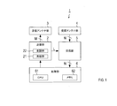
- the radar device 1 includes a transmitting unit 2, a transmitting antenna unit 3, a receiving antenna unit 4, a receiving unit 5, and a processing unit 6.
- the transmission antenna unit 3 has one or more antennas used for transmission.
- the reception antenna unit 4 has one or more antennas used for reception. However, at least one of the transmitting antenna unit 3 and the receiving antenna unit 4 has a plurality of antennas.
- the radar device 1 is configured to have a plurality of transmission/reception channels with a combination of an antenna belonging to the transmission antenna unit 3 and an antenna belonging to the reception antenna unit 4 as a transmission/reception channel.
- the radar device 1 is assumed to include M antennas belonging to the transmitting antenna unit 3, N antennas belonging to the receiving antenna unit 4, and M ⁇ N transmitting/receiving channels. M ⁇ N is an integer of 2 or more.
- the arrangement intervals of the antennas belonging to the transmitting antenna unit 3 and the arrangement intervals of the antennas belonging to the receiving antenna unit 4 may be equal or unequal.
- the transmitter 2 transmits a transmission signal modulated by the FCM method.
- FCM is an abbreviation for Fast-Chirp Modulation.
- the transmitter 2 includes an oscillator 21 and a modulator 22.
- the oscillator 21 generates a continuous wave common signal.
- the oscillator 21 supplies the generated common signal to the modulator 22 and also to the receiver 5 as the local signal L.
- the oscillation unit 21 sets the measurement cycle Tf (for example, 50 ms) as one frame, and the frequency is linear with respect to the time during the measurement period Tm (for example, 10 ms) at the beginning of each frame.
- the chirp signal that changes to is continuously transmitted by a preset number of repetitions K (for example, 256).
- the transmitter 2 repeatedly transmits a chirp signal at each preset repetition period Tp.
- the modulation unit 22 branches the common signal generated by the oscillation unit 21 and generates M number of branch signals, which is the same number as the transmission antennas belonging to the transmission antenna unit 3.
- the modulator 22 performs phase shift modulation on each of the M branch signals to change the phase of the branch signal at each repeating cycle Tp. As a result, the modulator 22 generates M transmission signals to be supplied to each transmission antenna.
- the modulation unit 22 sets the phase rotation amount ⁇ of different magnitudes for each of the M branch signals, and the phase rotation amount ⁇ of the phase of the branch signal for each repetition cycle. To rotate.
- P the number of phases used in phase shift keying.
- P is an integer larger than M.
- the position of the transmission signal which is the signal after modulation with respect to the branch signal (that is, the common signal) that is the signal before modulation.
- the phase difference is 0° in all the repeating cycles Tp.
- the modulator 22 sets the number of phases P, selects M types of phase rotation amounts to be used for phase shift modulation among P types of phase rotation amounts ⁇ , and selects M types of phase rotation amounts and M transmissions. It is configured so that the setting of the correspondence relationship with the antenna can be changed appropriately.
- the setting may be changed according to an instruction from the processing unit 6 or automatically. When changing automatically, it may be performed according to a predetermined pattern or may be performed randomly.
- the reception unit 5 generates a beat signal that is a difference signal from the local signal L for each of the N reception signals output from each reception antenna belonging to the reception antenna unit 4, and generates the beat signal.
- the beat signal thus generated is sampled and supplied to the processing unit 6.
- the processing unit 6 is an electronic control unit mainly composed of a microcomputer including a CPU 61 and a memory 62.
- the memory 62 is, for example, a ROM and a RAM.
- Various functions of the microcomputer are realized by the CPU 61 executing a program stored in the non-transitional substantive recording medium.
- the memory 62 corresponds to a non-transitional substantive recording medium storing a program. By executing this program, the method corresponding to the program is executed.
- some or all of the functions executed by the CPU 61 may be configured as hardware by one or a plurality of ICs or the like. Further, the number of microcomputers forming the processing unit 6 may be one or plural.
- the object detection process is a process that is repeatedly executed after the processing unit 6 is activated.
- the processing unit 6 When the object detection process is executed, the processing unit 6 first sets a repetition period Tp, which is a parameter related to the common signal to be generated by the oscillating unit 21, in S10, as shown in FIG. Set to Tc (for example, 60 ⁇ s).
- the processing unit 6 executes the measurement process in S20.
- the procedure of the measurement process will be described.
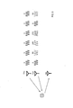
- the processing unit 6 When the measurement process is executed, the processing unit 6 first sets the phase number P used for the phase shift modulation in the modulation unit 22 in S210, as shown in FIG.
- the phase number P may be a fixed value, or the phase number P is set according to a predetermined pattern or randomly selected from a plurality of types of values each time this processing is executed. Good.
- the processing unit 6 selects M types of phase rotation amounts used for the phase shift modulation in the modulation unit 22 from P types of phase rotation amounts determined by the phase number P.
- the M kinds of phase rotation amounts are selected so that the rotation amounts are not evenly arranged within 360°, that is, non-uniform arrangement.
- the combinations of the phase rotation amounts are (0°, 90°), (90°, 180°), (180°, 270°). , (270°, 0°) are selectable, but (0°, 180°) and (90°, 270°) are not selectable.
- the selection of the amount of phase rotation may be always constant, or may be switched in a selectable combination according to a predetermined pattern or randomly each time this process is executed.
- the processing unit 6 sets the correspondence relationship between the M types of phase rotation amounts selected in S220 and each transmitting antenna in S230, as shown in FIG.
- This association may be assigned according to a preset rule, or may be assigned randomly. Further, the association may be always fixed, or may be randomly switched according to a predetermined pattern each time this process is executed.
- the phase of the transmission signal supplied to each of the transmission antennas TX1 and TX2 changes.
- the processing unit 6 determines in S240 whether it is the measurement start timing, as shown in FIG. When it is not the measurement start timing, the processing unit 6 waits by repeating the process of S240 until the measurement start timing. When it is the measurement start timing, the processing unit 6 moves to S250.
- the measurement start timing is a timing at which frames whose length is determined by the measurement cycle Tf are switched.
- the processing unit 6 operates the transmitting unit 2 according to the setting result and carries out radar measurement. Specifically, the transmitter 2 is caused to repeatedly transmit the chirp signal for each repeating period Tp during the measurement period Tm, and the sampling result of the beat signal generated from the received signal is acquired.
- the processing unit 6 frequency-analyzes the sampling result of the beat signal obtained from the N receiving antennas for each receiving antenna and for each chirp signal, thereby performing K analysis on each of the N receiving antennas. Calculate the distance spectrum for each. In each distance spectrum, a peak appears at a frequency according to the time required to reciprocate the object reflecting the radiation wave transmitted from the transmitting antenna (that is, the distance to the object).
- step S270 the processing unit 6 calculates the velocity spectrum for each receiving antenna using the N ⁇ K distance spectrums calculated in step S260. Specifically, signals of the same frequency bin are extracted from the K distance spectrums of the receiving antenna of interest, and the frequency analysis processing in the time axis direction is executed on the extracted signals. This process is performed for all frequency bins (ie distances).
- Doppler observation range the range in which the Doppler frequency is observed (hereinafter, Doppler observation range) is determined by the repeat cycle Tp. Further, the Doppler frequency is detected at M points among the points obtained by dividing the Doppler observation range into P, as shown in FIG. In FIG. 9, the upper limit of the Doppler observation range is normalized to 1.
- these M Doppler frequencies are shifted by an amount according to the relative velocity, and depending on the magnitude of the relative velocity, the frequency wrapping occurs. To do.
- a two-dimensional spectrum (hereinafter referred to as a reception spectrum) that represents the distance and the relative speed to the object that reflected the radar wave is generated for each reception antenna.
- FIG. 10 shows the reception spectrum when there are four reception antennas, and the peaks detected in the reception spectrum.
- the processing unit 6 uses the reception spectrum for each reception antenna in S280 as shown in FIG.
- the information generation process for calculating the existing azimuth is executed, and the measurement process ends.
- the processing unit 6 When the information generation processing is executed, the processing unit 6 first performs incoherent integration on the N reception spectra generated for each reception antenna in S270 in S310 to obtain one as shown in FIG. Calculate two integrated spectra g(r,v).
- the integrated spectrum g(r,v) is calculated using equation (1), where the received spectrum for each receiving antenna is represented by s(r,v,Rch). r is a distance, v is a normalized Doppler velocity with the velocity corresponding to the upper limit frequency of the Doppler observation range being 1, and Rch is a number for identifying the receiving antenna.
- the processing unit 6 sets, as a candidate distance, a distance at which M or more peaks having an intensity equal to or higher than a preset threshold value are detected on the integrated spectrum, and in S330 to S380 below, among the candidate distances.
- the distance that has not been selected as the target of the processing of 1 is selected as the target distance r.
- the processing unit 6 sets the speed corresponding to the peak not yet selected as a processing target in the following S340 to S370 among the plurality of peaks detected at the target distance r selected in S320 to the target speed. Select as v. Here, the processing unit 6 selects in order from the smallest speed.
- the processing unit 6 determines whether or not there is a peak (that is, a secondary maximum point) on the integrated spectrum for all the corresponding points estimated in S340, and if a positive determination is made, S360. If the determination is negative, the process proceeds to S390.
- a peak that is, a secondary maximum point
- the processing unit 6 determines whether or not the candidate peak group satisfies the power condition. If the determination is affirmative, the processing shifts to S370, and if the determination is negative, the processing shifts to S390.
- the power condition it is used that the signal intensity difference of the peaks belonging to the candidate peak group is within the preset allowable range. This is based on the finding that the signal intensities of the peaks based on the reflected waves from the same object should be similar.
- the processing unit 6 determines whether or not the candidate peak group satisfies the phase condition. If the determination is affirmative, the processing shifts to S380, and if the determination is negative, the processing shifts to S390.
- the phase condition the phase difference between the reference reception channel and the reception channels other than the reference reception channel is calculated, and the difference between the phase differences between the candidate peaks is within the preset allowable range. This is based on the knowledge that all peaks based on reflected waves from the same object should come from the same direction, and the phase differences between reception peaks that arrive from the same direction are of similar magnitude. Based on the fact that Hereinafter, the candidate peak group for which an affirmative determination is made in S370 is referred to as the same object peak group.
- the processing unit 6 registers the set of the target distance r and the target speed v as the object information. Further, the processing unit 6 adds the azimuth ⁇ calculated as follows to the object information. That is, each peak corresponding to the M identical object peak groups is extracted from each of the N received spectra calculated for each receiving antenna. The extracted M ⁇ N peaks are regarded as the received signals from the M ⁇ N transmission/reception channels, and the azimuth ⁇ of the object is calculated by executing the azimuth detection processing such as MUSIC or beamforming.
- MUSIC is an abbreviation for Multiple signal classification.
- the processing unit 6 determines whether or not all the peaks (that is, the velocities) detected at the target distance r are selected as the target velocity v, and when the affirmative determination is made, the process proceeds to S400. If the determination is negative, the process proceeds to S330.
- the processing unit 6 determines whether or not all the candidate distances have been selected as the target distance r. If an affirmative determination is made, the information generation processing ends, and if a negative determination is made, S320 is performed. Move to.
- the relative speed, the distance, and the azimuth calculated in the measurement process of S20 are described as v 1 , r 1 , and ⁇ 1 , respectively.
- the processing unit 6 sets the repetition cycle Tp to a value obtained by adding the reference time Tc and the preset fluctuation time ⁇ T in S30, as shown in FIG.
- the processing unit 6 executes the measurement process in the same manner as in S20.
- the relative speed, the distance, and the azimuth calculated in the measurement process of S40 will be described as v 2 , r 2 , and ⁇ 2 , respectively.
- the processing unit 6 sets the repetition cycle Tp to a value obtained by subtracting the fluctuation time ⁇ T from the reference time Tc in S50.
- the processing unit 6 executes the measurement process in the same manner as in S20.
- the relative velocity, the distance, and the azimuth calculated in the measurement process of S60 will be described as v 3 , r 3 , and ⁇ 3 , respectively.
- the processing unit 6 executes posterior distribution calculation regarding speed in S80.
- stagger modulation is a method of changing the repetition period Tp for each measurement period Tf to randomly change the observation speed of the speed turnaround ghost to make it difficult to establish a history connection.
- the repeating cycle Tp is alternately changed for each measurement cycle Tf between the reference time Tc and the time obtained by adding the reference time Tc and the variation time ⁇ T.
- the observable velocity range of the observation velocity v obs is represented by “ ⁇ /4Tp ⁇ v obs ⁇ + ⁇ /4Tp”, where ⁇ is the wavelength of the chirp signal.
- FIG. 13 shows the correspondence relationship between the actual relative speed and the observed speed when the repeating cycle Tp is the reference time Tc and when the repeating cycle Tp is the time obtained by adding the reference time Tc and the fluctuation time ⁇ T.
- FIG. 13 when the repeating cycle Tp is the reference time Tc, the repeating cycle Tp is the first repeating cycle Tp1, and the repeating cycle Tp is the time obtained by adding the reference time Tc and the variation time ⁇ T.
- the repetition cycle Tp in is referred to as a second repetition cycle Tp2.
- straight lines L1, L2, L3 show the correspondence relationship in the first repeating cycle Tp1
- straight lines L4, L5, L6 show the correspondence relationship in the second repeating cycle Tp2.
- the observed speed v obs is the speed Vo when the repeat cycle Tp is the first repeat cycle Tp1
- the actual relative speed is assumed to be the speed Vr1, the speed Vr2, and the speed Vr3.
- Vo Vr1.
- the speed Vr2 corresponds to the speed of one turn back on the positive side.
- the speed Vr3 corresponds to the speed of one turn back on the negative side.
- the observed speed v obs is the speed Vo when the repeat cycle Tp is the second repeat cycle Tp2
- the actual relative speeds are assumed to be the speed Vr1, the speed Vr4, and the speed Vr5.
- the speed Vr4 corresponds to the speed of one turn back on the positive side.
- the speed Vr5 corresponds to the speed of one turn back on the negative side.
- the repeat cycle Tp is the reference time Tc in the first cycle
- the repeat cycle Tp is the time obtained by adding the reference time Tc and the fluctuation time ⁇ T in the second cycle.
- the repetition cycle Tp is the time obtained by subtracting the fluctuation time ⁇ T from the reference time Tc.
- Graphs GR1, GR2, and GR3 show the speed and distance observed by the radar device 1, with the vertical axis representing velocity and the horizontal axis representing distance.
- Graphs GR1, GR2 and GR3 are the observation results at the 1st, 2nd and 3rd cycles, respectively.
- the observable speed range in the first cycle is ⁇ 70 km/h to +70 km/h
- the observable speed range in the second cycle is ⁇ 50 km/h to +50 km/h
- the observable speed range in the third cycle is ⁇ 90 km/h to +90 km/h.
- the first hypothesis is that the actual relative speed is a speed that is one turn back on the positive side.
- the second hypothesis assumes that the actual relative velocity is the unfolded velocity.
- the third hypothesis is that the actual relative speed is the speed that is one turn back on the negative side.
- the first hypothesis is that the actual speed is the speed Vr11, which is one turn back on the positive side, as indicated by the circle C1.
- the second hypothesis is assumed to be the actual speed Vo1 at which the speed is not folded back.
- the third hypothesis is that the actual speed is the speed Vr12 which is one turn on the negative side.
- the observation speed v obs in the second cycle is the speed Vo2, as indicated by the point Po2 in the graph GR2.
- Prediction gates G1, G2, G3 respectively indicate ranges in which the speed and distance in the second cycle are predicted based on the first, second, and third hypotheses in the first cycle.
- the graph GR2 indicates that the observation result of the second cycle is included in the prediction gate G1 of the first hypothesis.
- Circle C4 indicates the speed of one turn back on the positive side.
- the circle C5 indicates the speed of one turn back on the negative side.
- the observation speed v obs in the third cycle is the speed Vo3, as indicated by the point Po3 in the graph GR3.
- Prediction gates G4, G5, G6 respectively indicate ranges in which the speed and distance in the third cycle are predicted based on the first, second, and third hypotheses in the first cycle.
- the graph GR3 indicates that the observation result of the third cycle is included in the prediction gate G4 of the first hypothesis.
- the circle C6 indicates the speed of one turn back on the positive side.
- Circle C7 indicates the speed of one turn back on the negative side.
- the radar device 1 determines that the actual speed is on the positive side. It can be determined that the speed is one turn.
- ⁇ v,0 is the observation speed in the first cycle.
- ⁇ v,+1 is the speed of the first cycle in the case where the first hypothesis that assumes one turn on the positive side is adopted.
- ⁇ v, ⁇ 1 is the speed of the first cycle in the case where the third hypothesis that assumes one turn on the negative side is adopted.
- ⁇ v,0 is the accuracy when the second hypothesis that does not assume folding is adopted.
- ⁇ v,+1 is the accuracy when the first hypothesis is adopted.
- ⁇ v, ⁇ 1 is the accuracy when the third hypothesis is adopted.
- ⁇ v,+1 ,v 1 ,v 2 ) is the accuracy distribution of the speed in the second cycle when the first hypothesis is adopted.
- ⁇ v,0 , v 1 , v 2 ) is the accuracy distribution of the speed in the second cycle when the second hypothesis is adopted.
- ⁇ v, ⁇ 1 ,v 1 , v 2 ) is the accuracy distribution of the speed in the second cycle when the third hypothesis is adopted.
- ⁇ v,+1 ,v 1 ,v 2 ,v 3 ) is the accuracy distribution of the speed at the third cycle when the first hypothesis is adopted.
- ⁇ v,0 , v 1 , v 2 , v 3 ) is the accuracy distribution of the speed at the third cycle when the second hypothesis is adopted.
- ⁇ v, ⁇ 1 ,v 1 , v 2 , v 3 ) is the accuracy distribution of the speed at the third cycle when the third hypothesis is adopted.
- Equation (3) holds. Note that p( ⁇ v,i
- Equation (4) assuming the gamma distribution shown in Equation (5) for the prior distribution p( ⁇ v,i
- the hyper parameter a N and the hyper parameter b N in the equation (6) are calculated by the equation (7) and the equation (8), respectively.
- V n,i in the equation (8) is the i-fold back velocity of the observation velocity at the n-th cycle. Then, the expected value of the speed accuracy ⁇ v,i is easily calculated by the equation (9).
- the processing unit 6 uses the relative velocities v 1 , v 2 , and v 3 calculated in the measurement process of S20, S40, and S60 to calculate the accuracy ⁇ by the equations (7), (8), and (9).
- the expected values E[ ⁇ v,+1 ], E[ ⁇ v,0 ], E[ ⁇ v, ⁇ 1 ] of v,+1 , ⁇ v,0 , ⁇ v, ⁇ 1 are calculated.
- the processing unit 6 executes posterior distribution calculation regarding the distance in S90.
- ⁇ r,0 is the accuracy of the distance when the second hypothesis is adopted.
- ⁇ r,+1 is the accuracy of the distance when the first hypothesis is adopted.
- ⁇ r, ⁇ 1 is the accuracy of the distance when the third hypothesis is adopted.
- the first, second, and third hypotheses are adopted.
- the accuracy distribution of the distance in the second cycle in the case is calculated.
- the accuracy distribution of the distance in the third cycle when the first, second, and third hypotheses are adopted is calculated.
- ⁇ v,+1 ,v 1 , r 1 , r 2 ) is the accuracy distribution of the distance in the second cycle when the first hypothesis is adopted.
- ⁇ v,0 , v 1 , r 1 , r 2 ) is the accuracy distribution of the distance in the second cycle when the second hypothesis is adopted.
- ⁇ v, ⁇ 1 ,v 1 , r 1 , r 2 ) is the accuracy distribution of the distance in the second cycle when the third hypothesis is adopted.
- ⁇ v,+1 ,v 1 , r 1 , r 2 , r 3 ) is the accuracy distribution of the distance at the third cycle when the first hypothesis is adopted.
- ⁇ v,0 , v 1 , r 1 , r 2 , r 3 ) is the accuracy distribution of the distance at the third cycle when the second hypothesis is adopted.
- ⁇ v, ⁇ 1 ,v 1 , r 1 , r 2 , r 3 ) is the accuracy distribution of the distance at the third cycle when the third hypothesis is adopted.
- the accuracy distribution of the distance in the third cycle when the first, second, and third hypotheses are adopted can be calculated by the equation (10).
- equation (10) assuming the gamma distribution shown in equation (11) in the prior distribution p( ⁇ r,i
- the hyper parameter a N and the hyper parameter b N in the equation (12) are calculated by the equation (13) and the equation (14), respectively.
- T in equation (14) is the cycle interval time. Then, the expected value of the distance accuracy ⁇ r,i (hereinafter, distance accuracy ⁇ r,i ) is easily calculated by the equation (15).
- the processing unit 6 uses the relative speed v 1 and the distances r 1 , r 2 , r 3 calculated in the measurement processing of S20, S40, S60, and formulas (13), (14), (15).
- expected values E[ ⁇ r,+1 ], E[ ⁇ r,0 ], E[ ⁇ r, ⁇ 1 ] of accuracy ⁇ r,+1 , ⁇ r,0 , ⁇ r, ⁇ 1 are calculated.
- the processing unit 6 executes posterior distribution calculation regarding the bearing in S100.
- the first, second, and third hypotheses are adopted.
- the accuracy distribution of the azimuth in the second cycle is calculated.
- the azimuth ⁇ 3 is obtained in the third cycle
- the accuracy distribution of the azimuth in the third cycle when the first, second, and third hypotheses are adopted is calculated.
- v 1 , ⁇ 1 , ⁇ 2 ) is the accuracy distribution of the azimuth in the second cycle when the first hypothesis is adopted.
- v 1 , ⁇ 1 , ⁇ 2 ) is the accuracy distribution of the azimuth in the second cycle when the second hypothesis is adopted.
- v 1 , ⁇ 1 , ⁇ 2 ) is the accuracy distribution of the azimuth in the second cycle when the third hypothesis is adopted.
- v 1 , ⁇ 1 , ⁇ 2 , ⁇ 3 ) is the accuracy distribution of the azimuth at the third cycle when the first hypothesis is adopted.
- v 1 , ⁇ 1 , ⁇ 2 , ⁇ 3 ) is the accuracy distribution of the azimuth at the third cycle when the second hypothesis is adopted.
- v 1 , ⁇ 1 , ⁇ 2 , ⁇ 3 ) is the accuracy distribution of the azimuth at the third cycle when the third hypothesis is adopted.
- v 1 , ⁇ 1 , ⁇ 2 , ⁇ 3 ) in the third cycle when the first, second, and third hypotheses are adopted is It has a Gauss-gamma distribution.
- Expression (16) assuming a Gauss-Gamma distribution for the prior distribution p( ⁇ ⁇ , i , ⁇ ⁇ , i
- Equation (17) ⁇ N , ⁇ N , a N , and b N in equation (17) are represented by equations (18), (19), (20), and (21), respectively. Then, the expected value of the azimuth accuracy ⁇ ⁇ ,i is simply calculated by the equation (22).
- the processing unit 6 uses the relative velocity v 1 and the azimuths ⁇ 1 , ⁇ 2 , and ⁇ 3 calculated in the measurement process of S20, S40, and S60 to calculate the azimuth accuracy according to the equations (18) to (22).
- Expected values E[ ⁇ ⁇ ,+1 ], E[ ⁇ ⁇ ,0 ], E[ ⁇ ⁇ , ⁇ 1 ] of ⁇ ⁇ ,+1 , ⁇ ⁇ ,0 , ⁇ ⁇ , ⁇ 1 are calculated.
- the processing unit 6 determines the target speed by using the expected value calculated in S80, S90, and S100, and once ends the object detection process. Specifically, the processing unit 6 first calculates the total expected value Et1 of the first hypothesis, the total expected value Et2 of the second hypothesis, and the total expected value Et3 of the third hypothesis, respectively, using equations (23), ( 24) and (25). Then, the processing unit 6 determines, as the target speed, the speed based on the hypothesis corresponding to the largest expected value among all the expected values Et1, Et2, Et3.
- the radar device 1 configured in this way includes a transmitter 2, a receiver 5, and a processor 6.
- the transmission unit 2 sets the preset measurement cycle Tf as one cycle, and the radar wave whose frequency changes with time is preset for each preset repetition cycle Tp each time the measurement cycle Tf elapses.
- the set number of repeats K is repeatedly transmitted.
- the processing unit 6 changes the repetition cycle Tp each time the measurement cycle Tf elapses.
- the receiving unit 5 and the processing unit 6 By receiving the radar wave reflected by the object, the receiving unit 5 and the processing unit 6 detect at least the relative speed with respect to the object that reflects the radar wave (hereinafter referred to as a reflecting object) as an observation speed.
- the processing unit 6 calculates each of the first hypothesis, the second hypothesis, and the third hypothesis calculated from p( ⁇ v,i
- One of the first hypothesis, the second hypothesis, and the third hypothesis is selected based on p( ⁇ v,i
- the radar device 1 has p( ⁇ v,+1
- the processing unit 6 further detects the distance to the reflecting object as the observation distance. Then, the processing unit 6 adds at least p( ⁇ r,i
- the radar device 1 can select the hypothesis using the distance accuracy ⁇ r,i in addition to the speed accuracy ⁇ v,i . Therefore, the radar device 1 further suppresses the occurrence of a situation in which it is impossible to determine which of the first, second, and third hypotheses is correct, and detects the velocity of the object. The accuracy can be further improved.
- the processing unit 6 further detects the azimuth in which the reflecting object exists as the observation azimuth. Then, the processing unit 6 adds at least p( ⁇ ⁇ , i , ⁇ ⁇ , i
- the radar device 1 can select the hypothesis using the azimuth accuracy ⁇ ⁇ ,i in addition to the speed accuracy ⁇ v,i . Therefore, the radar device 1 further suppresses the occurrence of a situation in which it is impossible to determine which of the first, second, and third hypotheses is correct, and detects the velocity of the object. The accuracy can be further improved.
- ⁇ v,i ,v 1 , r 1 ) are gamma distributions.
- the radar device 1 is provided with p( ⁇ v,i
- v 1 , ⁇ 1 ) is a Gauss-gamma distribution.
- the radar device 1 can reduce the amount of calculation for calculating p( ⁇ ⁇ , i , ⁇ ⁇ , i
- the chirp signal corresponds to the radar wave
- S10, S30, and S50 correspond to the processing as the repetition cycle setting unit
- S20, S40, and S60 correspond to the processing as the object detecting unit
- S80 to S110 correspond to processing as a hypothesis selection unit.
- ⁇ v,i ,v 1 ) corresponds to the velocity accuracy prior distribution
- 3 cycles corresponds to the number of distribution calculations
- ⁇ v,i ,v 1 , V 2 , v 3 ) corresponds to the velocity accuracy posterior distribution.
- ⁇ v,i , v 1 , r 1 ) corresponds to the distance accuracy prior distribution
- ⁇ v,i , v 1 , r 1 , r 2 , r 2 , r 3 ) corresponds to the distance accuracy posterior distribution
- v 1 , ⁇ 1 ) corresponds to the azimuth accuracy prior distribution
- v 1 , ⁇ 1 , ⁇ 2 , ⁇ 3 ) corresponds to the azimuth accuracy posterior distribution
- the function of one component in the above embodiment may be shared by a plurality of components, or the function of a plurality of components may be exerted by one component. Further, a part of the configuration of the above embodiment may be omitted. Further, at least a part of the configuration of the above-described embodiment may be added to or replaced with the configuration of the other above-described embodiment.
- the present disclosure is provided in various forms such as a system having the radar device 1 as a constituent element, a program for causing a computer to function as the radar device 1, a medium in which the program is recorded, and a speed detection method. Can also be realized.
Landscapes
- Engineering & Computer Science (AREA)
- Radar, Positioning & Navigation (AREA)
- Remote Sensing (AREA)
- Physics & Mathematics (AREA)
- Computer Networks & Wireless Communication (AREA)
- General Physics & Mathematics (AREA)
- Electromagnetism (AREA)
- Radar Systems Or Details Thereof (AREA)
Abstract
レーダ装置(1)は、送信部(2)と繰返周期設定部(6,S10,S30,S50)と物体検出部(5,6,S20,S40,S60)と仮説選択部(6,S80,S110)とを備える。送信部は、測定周期を1回のサイクルとして、時間に対して周波数が変化するレーダ波を繰返周期毎に繰り返して送信する。繰返周期設定部は、測定周期が経過する毎に繰返周期を変化させる。物体検出部は、物体で反射したレーダ波を受信することによって、反射物体との相対速度を観測速度として検出する。仮説選択部は、速度精度事前分布と、分布計算回数分の観測速度の検出結果とにより算出される第1,2,3仮説についての速度精度事後分布に基づき、第1,2,3仮説の何れか1つの仮説を選択する。
Description
本国際出願は、2018年11月28日に日本国特許庁に出願された日本国特許出願第2018-222514号に基づく優先権を主張するものであり、日本国特許出願第2018-222514号の全内容を参照により本国際出願に援用する。
本開示は、レーダ波を送受信することにより、レーダ波を反射した物体を検出するレーダ装置に関する。
特許文献1には、アンテナを介して所定の繰返周期で繰り返し送信されて物体で反射したレーダ波を受信することにより、物体の相対速度(以下、ターゲット速度)を算出するレーダ装置が記載されている。
特許文献1に記載のレーダ装置のように、所定の繰返周期Tpで繰り返されるレーダ波を送受信する場合には、観測速度の観測可能速度範囲は、λをレーダ波の波長として、-λ/4Tpから+λ/4Tpまでとなる。この観測可能速度範囲を超える相対速度で移動する物体を検出する場合には、速度の折り返しが発生し、正しいターゲット速度を検出することができない。
この対策として、サイクル毎に繰返周期を変化させることで、サイクル毎に観測可能速度範囲を変化させるスタガ処理が一般的に用いられる。このスタガ処理を利用する場合には、数サイクルに亘る観測速度の変化を観測し、ターゲット速度の折り返し曖昧性を解く必要がある。従来、数サイクルに亘るターゲット速度の仮定を単純に複数設定し、トラッキングが数サイクルで繋がり続けた仮定に対応するターゲット速度を真のターゲット速度とすることにより、折り返し曖昧性を解いていた。
しかし、発明者の詳細な検討の結果、上記の解き方では、間違っている仮説であっても、トラッキングが数サイクルで繋がり続けてしまった場合には、どの仮説に対応するターゲット速度を真のターゲット速度とするかを決定することができなくなってしまい、物体の速度の検出精度が低下してしまうという課題が見出された。
本開示は、物体の速度の検出精度を向上させる。
本開示の一態様は、送信部と、繰返周期設定部と、物体検出部と、仮説選択部とを備えるレーダ装置である。
送信部は、予め設定された測定周期を1回のサイクルとして、測定周期が経過する毎に、時間に対して周波数が変化するレーダ波を予め設定された繰返周期毎に予め設定された繰返数だけ繰り返して送信するように構成される。
繰返周期設定部は、測定周期が経過する毎に繰返周期を変化させるように構成される。
物体検出部は、物体で反射したレーダ波を受信することによって、少なくとも、レーダ波を反射した物体である反射物体との相対速度を、観測速度として検出するように構成される。
仮説選択部は、速度精度事前分布と、分布計算回数分の観測速度の検出結果とにより算出される第1仮説、第2仮説および第3仮説のそれぞれについての速度精度事後分布に基づき、第1仮説、第2仮説および第3仮説の何れか1つの仮説を選択するように構成される。
第1仮説は、観測速度が、繰返周期に基づいて設定される観測可能速度範囲の上限より大きい相対速度の折り返しによる検出結果であると仮定する仮説である。第2仮説は、観測速度が、相対速度の折り返しがない場合の検出結果であると仮定する仮説である。第3仮説は、観測速度が、観測可能速度範囲の下限より小さい相対速度の折り返しによる検出結果であると仮定する仮説である。
速度精度は、相対速度の精度である。速度精度事前分布は、速度精度に関する事前分布である。速度精度事後分布は、予め設定された分布計算回数のサイクルが経過した後における速度精度に関する事後分布である。
このように構成された本開示のレーダ装置は、第1仮説に基づいて算出される速度精度事後分布と、第2仮説に基づいて算出される速度精度事後分布と、第3仮説に基づいて算出される速度精度事後分布とのうち、速度精度が最も高くなる速度精度事後分布に対応する仮説を選択することができる。従って、本開示のレーダ装置は、第1仮説、第2仮説および第3仮説のうち、少なくとも2つの仮説の速度精度事後分布で同時に速度精度が最高となる事態の発生を抑制できる。このため、本開示のレーダ装置は、第1仮説、第2仮説および第3仮説のうち、どの仮説が正しいかを決定することができなくなってしまうという事態の発生を抑制し、物体の速度の検出精度を向上させることができる。
以下に本開示の実施形態を図面とともに説明する。
本実施形態のレーダ装置1は、車両に搭載され、車両の周囲に存在する様々な物体を検出する。
レーダ装置1は、図1に示すように、送信部2と、送信アンテナ部3と、受信アンテナ部4と、受信部5と、処理部6とを備える。
送信アンテナ部3は、送信に使用される一つ以上のアンテナを有する。受信アンテナ部4は、受信に使用される一つ以上のアンテナを有する。但し、送信アンテナ部3と受信アンテナ部4とのうち、少なくとも一方は複数のアンテナを有する。
つまり、レーダ装置1は、送信アンテナ部3に属するアンテナと、受信アンテナ部4に属するアンテナとの組み合わせを送受信チャネルとして、複数の送受信チャネルを有するように構成される。本実施形態では、レーダ装置1は、送信アンテナ部3に属するアンテナをM個、受信アンテナ部4に属するアンテナをN個備え、M×N個の送受信チャネルを備えるとする。M×Nは2以上の整数である。なお、送信アンテナ部3に属するアンテナの配置間隔と、受信アンテナ部4に属するアンテナの配置間隔とは、等間隔であっても不等間隔であってもよい。
送信部2は、FCM方式で変調された送信信号を送信する。FCMは、Fast-Chirp Modulationの略である。送信部2は、発振部21と、変調部22とを備える。発振部21は、連続波の共通信号を生成する。発振部21は、生成した共通信号を、変調部22に供給するとともに、ローカル信号Lとして受信部5にも供給する。また発振部21は、図2に示すように、測定周期Tf(例えば、50ms)を1フレームとして、各フレームの先頭の測定期間Tm(例えば、10ms)の間、時間に対して周波数が直線的に変化するチャープ信号を、予め設定された繰返数K(例えば、256個)だけ連続的に送信する。送信部2は、図3に示すように、予め設定された繰返周期Tp毎にチャープ信号を繰り返し送信する。
変調部22は、発振部21が生成した共通信号を分岐させ、送信アンテナ部3に属する送信アンテナと同数であるM個の分岐信号を生成する。変調部22は、M個の分岐信号のそれぞれについて、繰返周期Tp毎に分岐信号の位相を変化させる位相偏移変調を行う。これにより、変調部22は、送信アンテナのそれぞれに供給するM個の送信信号を生成する。位相偏移変調では、変調部22は、M個の分岐信号のそれぞれに対して互いに異なる大きさの位相回転量Δφを設定し、繰返周期毎に、その位相回転量Δφだけ分岐信号の位相を回転させる。
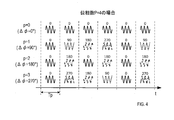
ここで、位相偏移変調で使用する位相の数をPとする。PはMより大きい整数である。変調部22は、p=0,1,2,…P-1として、Δφ=p×360°/Pで表されるP種類の位相回転量を用いる。例えば、P=4の場合、図4に示すように、p=0ではΔφ=0°となり、変調前の信号である分岐信号(すなわち、共通信号)に対する変調後の信号である送信信号の位相差は、全ての繰返周期Tpで0°となる。p=1ではΔφ=90°となり、共通信号に対する送信信号の位相差は繰返周期Tp毎に切り替わり、0°→90°→180°→270°→0°(以下同様)の順に変化する。p=2ではΔφ=180°となり、共通信号に対する送信信号の位相差は繰返周期毎に切り替わり、0°→180°→0°→180°→0°(以下同様)の順に変化する。p=3ではΔφ=270°となり、共通信号に対する送信信号の位相差は繰返周期毎に切り替わり、0°→270°→180°→90°→0°(以下同様)の順に変化する。
上述したようにP>Mに設定されるため、位相偏移変調には、P種類の位相回転量Δφの全種類が使用されることはなく、その一部が使用される。
変調部22は、位相数Pの設定、P種類の位相回転量Δφのうち位相偏移変調に使用するM種類の位相回転量の選択、選択されたM種類の位相回転量とM個の送信アンテナとの対応関係の設定を適宜変更できるように構成されている。設定の変更は、処理部6からの指示に従ってもよいし、自動的に行ってもよい。自動的に変更する場合は、予め決められたパターンに従って行ってもよいし、ランダムに行ってもよい。
受信部5は、図1に示すように、受信アンテナ部4に属する各受信アンテナから出力されるN個の受信信号のそれぞれについて、ローカル信号Lとの差信号であるビート信号を生成し、生成されたビート信号をサンプリングして処理部6に供給する。
処理部6は、CPU61およびメモリ62を備えたマイクロコンピュータを中心に構成された電子制御装置である。メモリ62は、例えばROMおよびRAMである。マイクロコンピュータの各種機能は、CPU61が非遷移的実体的記録媒体に格納されたプログラムを実行することにより実現される。この例では、メモリ62が、プログラムを格納した非遷移的実体的記録媒体に該当する。また、このプログラムの実行により、プログラムに対応する方法が実行される。なお、CPU61が実行する機能の一部または全部を、一つあるいは複数のIC等によりハードウェア的に構成してもよい。また、処理部6を構成するマイクロコンピュータの数は1つでも複数でもよい。
次に、処理部6が実行する物体検出処理の手順を説明する。物体検出処理は、処理部6が起動した後に繰り返し実行される処理である。
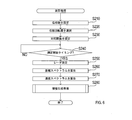
物体検出処理が実行されると、処理部6は、図5に示すように、まずS10にて、発振部21に生成させる共通信号に関するパラメータである繰返周期Tpを、予め設定された基準時間Tc(例えば、60μs)に設定する。
処理部6は、S20にて、測定処理を実行する。ここで、測定処理の手順を説明する。
測定処理が実行されると、処理部6は、図6に示すように、まずS210にて、変調部22での位相偏移変調に用いる位相数Pを設定する。位相数Pは、少なくとも送信アンテナ数Mより大きな値が用いられる。例えば、P=M+1に設定してもよい。位相数Pは固定値であってもよいし、本処理が実行される毎に予め決められたパターンに従って或いはランダムに複数種類の値の中から選択して位相数Pが設定されるようにしてもよい。
処理部6は、S220にて、位相数Pによって決まるP種類の位相回転量のうち、変調部22での位相偏移変調に用いるM種類の位相回転量を選択する。M種類の位相回転量は、360°の中で各回転量が均等に配置されることがないように、すなわち、不均一な配置となるように選択される。
具体的には、PとMとが公約数を持たない場合は、任意に位相回転量を選択することができる。PとMとが公約数を有する場合は、配置間隔が同一パターンの繰り返しとなることがないように注意して選択する必要がある。
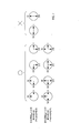
例えば、図7に示すように、P=4且つM=2である場合、位相回転量の組み合わせとして、(0°,90°)、(90°,180°)、(180°,270°)、(270°,0°)は選択可であるが、(0°,180°)、(90°,270°)は選択不可である。また、P=4且つM=3である場合、位相回転量の組み合わせとして、(0°,90°,180°)、(90°,180°,270°)、(180°,270°,0°)、(270°,0°,90°)の全てが選択可である。但し、本実施形態では、必ずΔφ=0°を含んだ組み合わせを選択する。
なお、位相回転量の選択は、常に一定でもよいし、本処理が実行される毎に、選択可能な組み合わせの中で、予め決められたパターンに従って又はランダムに切り替えられるようにしてもよい。
S220の処理が終了すると、処理部6は、図6に示すように、S230にて、S220で選択されたM種類の位相回転量と、各送信アンテナとの対応関係を設定する。この対応づけは、例えば、予め設定された規則に従って割り当てられてもよいし、ランダムに割り当てられてもよい。また、対応付けは、常に一定でもよいし、本処理が実行される毎に、予め決められたパターンに従って或いはランダムに切り替えられてもよい。
図8は、P=4且つM=2であり、位相回転量の組み合わせとして(0°,90°)が選択され、送信アンテナTX1にΔφ=0°、送信アンテナTX2にΔφ=90°を割り当てた場合に、送信アンテナTX1,TX2のそれぞれに供給される送信信号の位相が変化する様子を表現している。
S230の処理が終了すると、処理部6は、図6に示すように、S240にて、測定開始タイミングであるか否かを判断する。処理部6は、測定開始タイミングでない場合には、測定開始タイミングになるまで、S240の処理を繰り返すことで待機する。処理部6は、測定開始タイミングである場合には、S250に移行する。測定開始タイミングとは、測定周期Tfによって長さが決まるフレームが切り替わるタイミングである。
S250に移行すると、処理部6は、設定結果に従って送信部2を作動させ、レーダ測定を実施する。具体的には、送信部2に、測定期間Tmの間、繰返周期Tp毎にチャープ信号を繰り返し送信させ、その受信信号から生成されるビート信号のサンプリング結果を取得する。
処理部6は、S260にて、N個の受信アンテナから得られるビート信号のサンプリング結果を、受信アンテナ毎に、且つ、チャープ信号毎に周波数解析することによって、N個の受信アンテナのそれぞれについてK個ずつの距離スペクトラムを算出する。各距離スペクトラムでは、送信アンテナから送信された放射波を反射した物体を往復するのに要した時間(すなわち、物体までの距離)に応じた周波数にピークが出現する。
処理部6は、S270にて、S260にて算出されたN×K個の距離スペクトラムを用いて、受信アンテナ毎に速度スペクトラムを算出する。具体的には、着目する受信アンテナに関するK個の距離スペクトラムから、同一周波数ビンの信号を抽出し、抽出した信号に対して時間軸方向への周波数解析処理を実行する。この処理を全ての周波数ビン(すなわち、距離)について実行する。
速度スペクトラムでは、送信アンテナ部3からの放射波を反射した物体との相対速度がゼロである場合は、各送信アンテナに割り当てられた位相回転量に応じた周波数が、ドップラ周波数として抽出される。つまり、Δφ=0°に対応する信号成分の周波数は0Hzである。
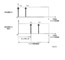
なお、ドップラ周波数が観測される範囲(以下、ドップラ観測範囲)は、繰返周期Tpによって決まる。また、ドップラ周波数は、図9に示すように、ドップラ観測範囲をP分割した地点のうち、M個の地点にて検出される。図9では、ドップラ観測範囲の上限が1に正規化されている。
また、速度スペクトラムでは、物体との間に相対速度がある場合は、これらM個のドップラ周波数は、相対速度に応じた大きさだけシフトし、相対速度の大きさによっては、周波数の折り返しが発生する。
これらS260およびS270の算出結果から、レーダ波を反射した物体との距離および相対速度を表す二次元スペクトラム(以下、受信スペクトラム)が、受信アンテナ毎に生成される。図10は、受信アンテナが4個である場合の受信スペクトラムと、受信スペクトラムで検出されるピークとを示す。
S270の処理が終了すると、処理部6は、図6に示すように、S280にて、受信アンテナ毎に、受信スペクトラムを用いて、レーダ波を反射した物体との距離および相対速度と、物体が存在する方位とを算出する情報生成処理を実行し、測定処理を終了する。
次に、S280で実行される情報生成処理の手順を説明する。
情報生成処理が実行されると、処理部6は、図11に示すように、まずS310にて、S270にて受信アンテナ毎に生成されたN個の受信スペクトラムを、インコヒーレント積分して、一つの統合スペクトラムg(r,v)を算出する。受信アンテナ毎の受信スペクトラムをs(r,v,Rch)で表すものとして、統合スペクトラムg(r,v)は、式(1)を用いて算出される。rは距離であり、vは、ドップラ観測範囲の上限周波数に対応する速度を1とする正規化ドップラ速度であり、Rchは、受信アンテナを識別する番号である。

処理部6は、S320にて、統合スペクトラム上で、予め設定された閾値以上の強度を有するピークがM個以上検出されている距離を候補距離として、候補距離のうち、以下のS330からS380での処理の対象として未だ選択されていない距離を、対象距離rとして選択する。
処理部6は、S330にて、S320で選択された対象距離rで検出される複数のピークのうち、以下のS340からS370での処理対象として未だ選択されていないピークに対応する速度を対象速度vとして選択する。ここでは、処理部6は、速度が小さいものから順番に選択する。
処理部6は、S340にて、対象速度vのピークが、位相回転量Δφ=0°に対応したピークであると仮定し、式(2)に従って、他の位相回転量に対応したピークが存在すると推定されるM-1個の対応点(r,vj)、但し、j=2~Mを算出する。x(j)は、S220で選択されたΔφ=0°以外の位相回転量である。v,vjは正規化されたドップラ周波数であり、0~1の値をとる。mod(a,m)は、aをmで割った後の余りを示す。

処理部6は、S350にて、S340で推定された対応点の全てについて、統合スペクトラム上でピーク(すなわち、二次極大点)が存在するか否かを判断し、肯定判断された場合はS360に移行し、否定判断された場合は、S390に移行する。以下では、対応点に対応するM個のピークを候補ピーク群という。
S360に移行すると、処理部6は、候補ピーク群が電力条件を満たすか否かを判断し、肯定判断された場合は、S370に移行し、否定判断された場合は、S390に移行する。ここでは、電力条件として、候補ピーク群に属するピークの信号強度差が、予め設定された許容範囲内にあることを用いる。これは、同一物体からの反射波に基づくピークの信号強度は、いずれも類似しているはずであるとの知見に基づく。
S370に移行すると、処理部6は、候補ピーク群が位相条件を満たすか否かを判断し、肯定判断された場合は、S380に移行し、否定判断された場合は、S390に移行する。ここでは、位相条件として、基準受信チャンネルとそれ以外の受信チャンネル位相差を算出し、候補ピーク間でこの位相差の差異が予め設定された許容範囲にあることを用いる。これは、同一物体からの反射波に基づくピークは、いずれも同じ方向から到来するはずであるとの知見に基づき、同じ方向から到来するピークの受信間位相差は、いずれも似たような大きさになることに基づく。以下では、S370にて肯定判断された候補ピーク群を、同一物体ピーク群という。
S380に移行すると、処理部6は、対象距離rと対象速度vとの組を、物体情報として登録する。更に、処理部6は、以下のようにして算出した方位θも物体情報に追加する。すなわち、受信アンテナ毎に算出されたN個の受信スペクトラムのそれぞれから、M個の同一物体ピーク群に対応する各ピークを抽出する。抽出されたM×N個のピークを、M×N個の送受信チャネルからの受信信号とみなして、MUSICまたはビームフォーミング等の方位検出処理を実行することで、物体の方位θを算出する。MUSICは、Multiple signal classificationの略である。
S390に移行すると、処理部6は、対象距離rで検出される全てのピーク(すなわち、速度)が、対象速度vとして選択された否かを判断し、肯定判断された場合はS400に移行し、否定判断された場合は、S330に移行する。
S400に移行すると、処理部6は、全ての候補距離が対象距離rとして選択されたか否かを判断し、肯定判断された場合は、情報生成処理を終了し、否定判断された場合は、S320に移行する。
以下、S20の測定処理で算出された相対速度、距離および方位をそれぞれ、v1,r1,θ1と表記する。
S20の処理が終了すると、処理部6は、図5に示すように、S30にて、繰返周期Tpを、基準時間Tcと、予め設定された変動時間ΔTとを加算した値に設定する。
そして処理部6は、S40にて、S20と同様にして、測定処理を実行する。以下、S40の測定処理で算出された相対速度、距離および方位をそれぞれ、v2,r2,θ2と表記する。
S40の処理が終了すると、処理部6は、S50にて、繰返周期Tpを、基準時間Tcから変動時間ΔTを減算した値に設定する。
そして処理部6は、S60にて、S20と同様にして、測定処理を実行する。以下、S60の測定処理で算出された相対速度、距離および方位をそれぞれ、v3,r3,θ3と表記する。
次に処理部6は、S80にて、速度に関する事後分布計算を実行する。
ここで、スタガ変調について説明する。スタガ変調は、測定周期Tf毎に繰返周期Tpを変化させることにより、速度折り返しゴーストの観測速度をランダムに変化させて、履歴接続され難くする手法である。
例えば、図12に示すように、測定周期Tf毎に、繰返周期Tpを、基準時間Tcと、基準時間Tcと変動時間ΔTとを加算した時間とで交互に変化させるとする。FCM方式では、観測速度vobsの観測可能速度範囲は、λをチャープ信号の波長として、「-λ/4Tp<vobs≦+λ/4Tp」で表される。
この観測可能速度範囲から外れる相対速度を有するターゲット物標は、速度が折り返されて観測されてしまう。
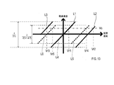
図13は、繰返周期Tpが基準時間Tcである場合と、繰返周期Tpが基準時間Tcと変動時間ΔTとを加算した時間である場合とにおける実際の相対速度と観測速度との対応関係を示す図である。図13の説明において、繰返周期Tpが基準時間Tcである場合における繰返周期Tpを第1繰返周期Tp1、繰返周期Tpが基準時間Tcと変動時間ΔTとを加算した時間である場合における繰返周期Tpを第2繰返周期Tp2という。図13において、直線L1,L2,L3は第1繰返周期Tp1における対応関係を示し、直線L4,L5,L6は第2繰返周期Tp2における対応関係を示す。
図13に示すように、繰返周期Tpが第1繰返周期Tp1であるときにおいて観測速度vobsが速度Voであったとすると、実際の相対速度は、速度Vr1、速度Vr2および速度Vr3が想定される。なお、Vo=Vr1である。速度Vr2は、正側で1回折り返した速度に相当する。速度Vr3は、負側で1回折り返した速度に相当する。
また、繰返周期Tpが第2繰返周期Tp2であるときにおいて観測速度vobsが速度Voであったとすると、実際の相対速度は、速度Vr1、速度Vr4および速度Vr5が想定される。速度Vr4は、正側で1回折り返した速度に相当する。速度Vr5は、負側で1回折り返した速度に相当する。
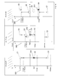
本実施形態では、図14に示すように、1サイクル目に、繰返周期Tpを基準時間Tcとし、2サイクル目に、繰返周期Tpを基準時間Tcと変動時間ΔTとを加算した時間とし、3サイクル目に、繰返周期Tpを基準時間Tcから変動時間ΔTを減算した時間としている。
グラフGR1、GR2,GR3は、縦軸を速度とし、横軸を距離として、レーダ装置1が観測した速度および距離を示す。グラフGR1、GR2,GR3はそれぞれ、1,2,3サイクル目における観測結果である。
図14では、1サイクル目における観測可能速度範囲は-70km/h~+70km/h、2サイクル目における観測可能速度範囲は-50km/h~+50km/h、3サイクル目における観測可能速度範囲は-90km/h~+90km/hである。
グラフGR1の点Po1で示すように1サイクル目の観測速度vobsが速度Vo1であった場合に、第1仮説、第2仮説および第3仮説を設定する。第1仮説は、実際の相対速度が正側で1回折り返した速度であると仮定する。第2仮説は、実際の相対速度が折り返していない速度であると仮定する。第3仮説は、実際の相対速度が負側で1回折り返した速度であると仮定する。
具体的には、1サイクル目において、第1仮説は、円C1で示すように、実際の速度が正側で1回折り返した速度Vr11であると仮定する。第2仮説は、実際の速度折り返していない速度Vo1であると仮定する。第3仮説は、実際の速度が負側で1回折り返した速度Vr12であると仮定する。
グラフGR2の点Po2で示すように、2サイクル目の観測速度vobsが速度Vo2であったとする。予測ゲートG1,G2,G3はそれぞれ、1サイクル目の第1,2,3仮説に基づいて2サイクル目の速度および距離を予測した範囲を示す。グラフGR2は、2サイクル目の観測結果が、第1仮説の予測ゲートG1内に含まれることを示している。円C4は、正側で1回折り返した速度を示す。円C5は、負側で1回折り返した速度を示す。
グラフGR3の点Po3で示すように、3サイクル目の観測速度vobsが速度Vo3であったとする。予測ゲートG4,G5,G6はそれぞれ、1サイクル目の第1,2,3仮説に基づいて3サイクル目の速度および距離を予測した範囲を示す。グラフGR3は、3サイクル目の観測結果が、第1仮説の予測ゲートG4内に含まれることを示している。円C6は、正側で1回折り返した速度を示す。円C7は、負側で1回折り返した速度を示す。
上述のように、2サイクル目および3サイクル目の観測結果がそれぞれ、第1仮説の予測ゲートG1および予測ゲートG4内に含まれているため、レーダ装置1は、実際の速度が、正側で1回折り返した速度であると判断することができる。
このように、スタガ変調を用いて、上記の第1,2,3仮説を設定することにより、実際の速度が、折り返していない速度であるか、正側で1回折り返した速度であるか、負側で1回折り返した速度であるかを判断することが可能である。
S80では、処理部6は、ターゲットの速度の推定値μv,i(i=-1,0,+1)を既知として、速度の精度λv,i(以下、速度精度λv,i)を推定する。
μv,0は、1サイクル目の観測速度である。μv,+1は、正側での1回の折り返しを仮定した第1仮説を採用した場合における1サイクル目の速度である。μv,-1は、負側での1回の折り返しを仮定した第3仮説を採用した場合における1サイクル目の速度である。
また、λv,0は、折り返しを仮定していない第2仮説を採用した場合における精度である。λv,+1は、第1仮説を採用した場合における精度である。λv,-1は、第3仮説を採用した場合における精度である。
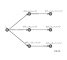
そして、図15に示すように、1サイクル目で観測速度v1が得られて、2サイクル目で観測速度v2が得られた場合において、第1,2,3仮説を採用した場合における2サイクル目の速度の精度分布が算出される。さらに、3サイクル目で観測速度v3が得られた場合において、第1,2,3仮説を採用した場合における3サイクル目の速度の精度分布が算出される。
p(λv,+1|μv,+1,v1,v2)は、第1仮説を採用した場合における2サイクル目の速度の精度分布である。p(λv,0|μv,0,v1,v2)は、第2仮説を採用した場合における2サイクル目の速度の精度分布である。p(λv,-1|μv,-1,v1,v2)は、第3仮説を採用した場合における2サイクル目の速度の精度分布である。
p(λv,+1|μv,+1,v1,v2,v3)は、第1仮説を採用した場合における3サイクル目の速度の精度分布である。p(λv,0|μv,0,v1,v2,v3)は、第2仮説を採用した場合における3サイクル目の速度の精度分布である。p(λv,-1|μv,-1,v1,v2,v3)は、第3仮説を採用した場合における3サイクル目の速度の精度分布である。
ベイズの定理より、式(3)が成立する。なお、式(3)におけるp(λv,i|μv,i,v)は事後分布であり、p(λv,i|μv,i)は事前分布である。

このため、第1,2,3仮説を採用した場合における3サイクル目の速度の精度分布は、式(4)で計算することができる。

式(4)において、事前分布p(λv,i|μv,i,v1)に、式(5)に示すガンマ分布を仮定すると、2サイクル目以降の事後分布は、式(6)に示すように、全てガンマ分布となる。式(6)におけるハイパーパラメータaNおよびハイパーパラメータbNはそれぞれ、式(7)および式(8)で算出される。式(8)におけるvn,iは、nサイクル目の観測速度のi回折り返し速度である。そして、速度精度λv,iの期待値は、式(9)で簡易に算出される。
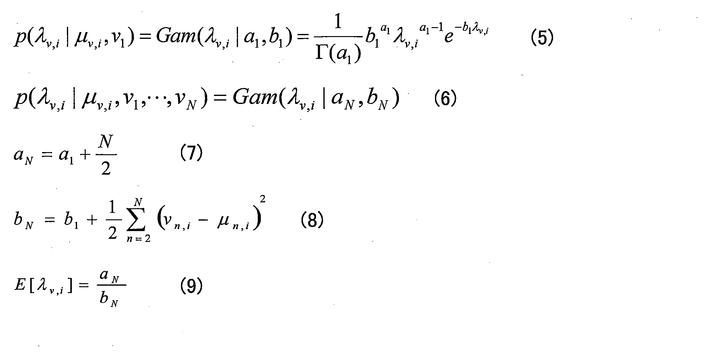
S80では、処理部6は、S20,S40,S60の測定処理で算出された相対速度v1,v2,v3を用いて、式(7),(8),(9)により、精度λv,+1,λv,0,λv,-1の期待値E[λv,+1],E[λv,0],E[λv,-1]を算出する。
次に処理部6は、S90にて、距離に関する事後分布計算を実行する。S90では、処理部6は、ターゲットの速度の推定値μv,i(i=-1,0,+1)を既知として、距離の精度λr,iを推定する。
また、λr,0は、第2仮説を採用した場合における距離の精度である。λr,+1は、第1仮説を採用した場合における距離の精度である。λr,-1は、第3仮説を採用した場合における距離の精度である。
そして、図16に示すように、1サイクル目で観測速度v1および距離r1が得られて、2サイクル目で距離r2が得られた場合において、第1,2,3仮説を採用した場合における2サイクル目の距離の精度分布が算出される。さらに、3サイクル目で距離r3が得られた場合において、第1,2,3仮説を採用した場合における3サイクル目の距離の精度分布が算出される。距離rnは、nサイクル目での観測距離である(n=1,2,3)。
p(λr,+1|μv,+1,v1,r1,r2)は、第1仮説を採用した場合における2サイクル目の距離の精度分布である。p(λr,0|μv,0,v1,r1,r2)は、第2仮説を採用した場合における2サイクル目の距離の精度分布である。p(λr,-1|μv,-1,v1,r1,r2)は、第3仮説を採用した場合における2サイクル目の距離の精度分布である。
p(λr,+1|μv,+1,v1,r1,r2,r3)は、第1仮説を採用した場合における3サイクル目の距離の精度分布である。p(λr,0|μv,0,v1,r1,r2,r3)は、第2仮説を採用した場合における3サイクル目の距離の精度分布である。p(λr,-1|μv,-1,v1,r1,r2,r3)は、第3仮説を採用した場合における3サイクル目の距離の精度分布である。
式(4)と同様にして、第1,2,3仮説を採用した場合における3サイクル目の距離の精度分布は、式(10)で計算することができる。

式(10)において、事前分布p(λr,i|μv,i,v1,r1)に、式(11)に示すガンマ分布を仮定すると、2サイクル目以降の事後分布は、式(12)に示すように、全てガンマ分布となる。式(12)におけるハイパーパラメータaNおよびハイパーパラメータbNはそれぞれ、式(13)および式(14)で算出される。式(14)におけるTは、サイクル間隔時間である。そして、距離の精度λr,i(以下、距離精度λr,i)の期待値は、式(15)で簡易に算出される。

S90では、処理部6は、S20,S40,S60の測定処理で算出された相対速度v1と距離r1,r2,r3を用いて、式(13),(14),(15)により、精度λr,+1,λr,0,λr,-1の期待値E[λr,+1],E[λr,0],E[λr,-1]を算出する。
次に処理部6は、S100にて、方位に関する事後分布計算を実行する。S100では、処理部6は、ターゲットの方位の推定値μθ,iおよび精度λθ,i(i=-1,0,+1)を未知として、方位の推定値μθ,iおよび方位の精度λθ,i(以下、方位精度λθ,i)の両方を同時推定する。
図17に示すように、1サイクル目で観測速度v1および方位θ1が得られて、2サイクル目で方位θ2が得られた場合において、第1,2,3仮説を採用した場合における2サイクル目の方位の精度分布が算出される。さらに、3サイクル目で方位θ3が得られた場合において、第1,2,3仮説を採用した場合における3サイクル目の方位の精度分布が算出される。方位θnは、nサイクル目での観測方位である(n=1,2,3)。
p(μθ,+1,λθ,+1|v1,θ1,θ2)は、第1仮説を採用した場合における2サイクル目の方位の精度分布である。p(μθ,0,λθ,0|v1,θ1,θ2)は、第2仮説を採用した場合における2サイクル目の方位の精度分布である。p(μθ,-1,λθ,-1|v1,θ1,θ2)は、第3仮説を採用した場合における2サイクル目の方位の精度分布である。
p(μθ,+1,λθ,+1|v1,θ1,θ2,θ3)は、第1仮説を採用した場合における3サイクル目の方位の精度分布である。p(μθ,0,λθ,0|v1,θ1,θ2,θ3)は、第2仮説を採用した場合における3サイクル目の方位の精度分布である。p(μθ,-1,λθ,-1|v1,θ1,θ2,θ3)は、第3仮説を採用した場合における3サイクル目の方位の精度分布である。
第1,2,3仮説を採用した場合における3サイクル目の方位の精度分布p(μθ,i,λθ,i|v1,θ1,θ2,θ3)の共役事前分布は、ガウス―ガンマ分布となる。式(16)に示すように、事前分布p(μθ,i,λθ,i|v1,θ1)にガウス―ガンマ分布を仮定すると、2サイクル目以降の事後分布は、式(17)に示すように、全てガンマ分布となる。式(17)におけるμN,λN,aN,bNはそれぞれ、式(18),(19),(20),(21)で表される。そして、方位精度λθ,iの期待値は、式(22)で簡易に算出される。

S100では、処理部6は、S20,S40,S60の測定処理で算出された相対速度v1と方位θ1,θ2,θ3を用いて、式(18)~(22)により、方位精度λθ,+1,λθ,0,λθ,-1の期待値E[λθ,+1],E[λθ,0],E[λθ,-1]を算出する。
次に処理部6は、S110にて、S80,S90,S100で算出された期待値を用いて、ターゲット速度を決定し、物体検出処理を一旦終了する。具体的には、処理部6は、まず、第1仮説の全期待値Et1と、第2仮説の全期待値Et2と、第3仮説の全期待値Et3とをそれぞれ、式(23),(24),(25)により算出する。そして処理部6は、全期待値Et1,Et2,Et3のうち、最も値が大きい全期待値に対応する仮説に基づく速度を、ターゲット速度として決定する。

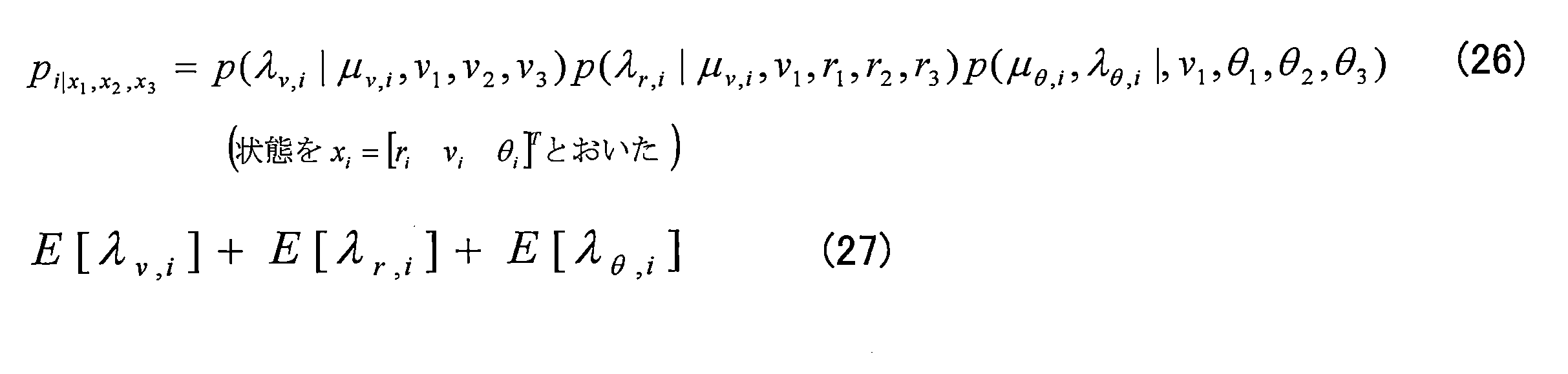
なお、第1,2,3仮説における3サイクル目の状態確率分布pi|x1,x2,x3(i=+1,0,-1)を、式(26)に示すように簡易化して、ナイーブベイズ的に考えると、最終的なトータルな精度は、式(27)で表される。
このように構成されたレーダ装置1は、送信部2と、受信部5と、処理部6とを備える。
送信部2は、予め設定された測定周期Tfを1回のサイクルとして、測定周期Tfが経過する毎に、時間に対して周波数が変化するレーダ波を予め設定された繰返周期Tp毎に予め設定された繰返数Kだけ繰り返して送信する。
処理部6は、測定周期Tfが経過する毎に繰返周期Tpを変化させる。
受信部5および処理部6は、物体で反射したレーダ波を受信することによって、少なくとも、レーダ波を反射した物体(以下、反射物体)との相対速度を、観測速度として検出する。
処理部6は、p(λv,i|μv,i,v1)と、3サイクル分の観測速度の検出結果とにより算出される第1仮説、第2仮説および第3仮説のそれぞれについてのp(λv,i|μv,i,v1,v2,v3)に基づき、第1仮説、第2仮説および第3仮説の何れか1つの仮説を選択する。
このようにレーダ装置1は、p(λv,+1|μv,+1,v1,v2,v3)と、p(λv,0|μv,0,v1,v2,v3)と、p(λv,-1|μv,-1,v1,v2,v3)とのうち、速度精度λv,iが最も高くなる事後分布に対応する仮説を選択することができる。従って、レーダ装置1は、第1仮説、第2仮説および第3仮説のうち、少なくとも2つの仮説の事後分布で同時に速度精度λv,iが最高となる事態の発生を抑制できる。このため、レーダ装置1は、第1仮説、第2仮説および第3仮説のうち、どの仮説が正しいかを決定することができなくなってしまうという事態の発生を抑制し、物体の速度の検出精度を向上させることができる。
また処理部6は、更に、反射物体との間の距離を、観測距離として検出する。そして処理部6は、p(λv,i|μv,i,v1,v2,v3)に加えて、少なくとも、p(λr,i|μv,i,v1,r1)と、3サイクル分の観測距離の検出結果とにより算出される第1仮説、第2仮説および第3仮説のそれぞれについてのp(λr,i|μv,i,v1,r1,r2,r3)に基づき、第1仮説、第2仮説および第3仮説の何れか1つの仮説を選択する。
これにより、レーダ装置1は、速度精度λv,iに加えて、距離精度λr,iを用いて、仮説を選択することができる。このため、レーダ装置1は、第1仮説、第2仮説および第3仮説のうち、どの仮説が正しいかを決定することができなくなってしまうという事態の発生を更に抑制し、物体の速度の検出精度を更に向上させることができる。
また処理部6は、更に、反射物体が存在する方位を、観測方位として検出する。そして処理部6は、p(λv,i|μv,i,v1,v2,v3)に加えて、少なくとも、p(μθ,i,λθ,i|v1,θ1)と、3サイクル分の観測方位の検出結果とにより算出される第1仮説、第2仮説および第3仮説のそれぞれについてのp(μθ,i,λθ,i|v1,θ1,θ2,θ3)に基づき、第1仮説、第2仮説および第3仮説の何れか1つの仮説を選択する。
これにより、レーダ装置1は、速度精度λv,iに加えて、方位精度λθ,iを用いて、仮説を選択することができる。このため、レーダ装置1は、第1仮説、第2仮説および第3仮説のうち、どの仮説が正しいかを決定することができなくなってしまうという事態の発生を更に抑制し、物体の速度の検出精度を更に向上させることができる。
また、p(λv,i|μv,i,v1)およびp(λr,i|μv,i,v1,r1)は、ガンマ分布である。これにより、レーダ装置1は、p(λv,i|μv,i,v1,v2,v3)およびp(λr,i|μv,i,v1,r1,r2,r3)を算出するための演算量を低減することができる。
また、p(μθ,i,λθ,i|v1,θ1)は、ガウス―ガンマ分布である。これにより、レーダ装置1は、p(μθ,i,λθ,i|v1,θ1,θ2,θ3)を算出するための演算量を低減することができる。
以上説明した実施形態において、チャープ信号はレーダ波に相当し、S10,S30,S50は繰返周期設定部としての処理に相当し、S20,S40,S60は物体検出部としての処理に相当し、S80~S110は仮説選択部としての処理に相当する。
また、p(λv,i|μv,i,v1)は速度精度事前分布に相当し、3サイクルは分布計算回数に相当し、p(λv,i|μv,i,v1,v2,v3)は速度精度事後分布に相当する。
また、p(λr,i|μv,i,v1,r1)は距離精度事前分布に相当し、p(λr,i|μv,i,v1,r1,r2,r3)は距離精度事後分布に相当する。
また、p(μθ,i,λθ,i|v1,θ1)は方位精度事前分布に相当し、p(μθ,i,λθ,i|v1,θ1,θ2,θ3)は方位精度事後分布に相当する。
以上、本開示の一実施形態について説明したが、本開示は上記実施形態に限定されるものではなく、種々変形して実施することができる。
[変形例1]
例えば上記実施形態では、速度、距離および方位に関する事後分布計算を実行する形態を示した。しかし、速度に関する事後分布計算のみを実行するようにしてもよいし、速度および距離に関する事後分布計算を実行するようにしてもよいし、速度および方位に関する事後分布計算を実行するようにしてもよい。
例えば上記実施形態では、速度、距離および方位に関する事後分布計算を実行する形態を示した。しかし、速度に関する事後分布計算のみを実行するようにしてもよいし、速度および距離に関する事後分布計算を実行するようにしてもよいし、速度および方位に関する事後分布計算を実行するようにしてもよい。
また、上記実施形態における1つの構成要素が有する機能を複数の構成要素に分担させたり、複数の構成要素が有する機能を1つの構成要素に発揮させたりしてもよい。また、上記実施形態の構成の一部を省略してもよい。また、上記実施形態の構成の少なくとも一部を、他の上記実施形態の構成に対して付加、置換等してもよい。
上述したレーダ装置1の他、当該レーダ装置1を構成要素とするシステム、当該レーダ装置1としてコンピュータを機能させるためのプログラム、このプログラムを記録した媒体、速度検出方法など、種々の形態で本開示を実現することもできる。
Claims (6)
- 予め設定された測定周期を1回のサイクルとして、前記測定周期が経過する毎に、時間に対して周波数が変化するレーダ波を予め設定された繰返周期毎に繰り返して送信するように構成された送信部(2)と、
前記測定周期が経過する毎に前記繰返周期を変化させるように構成された繰返周期設定部(6,S10,S30,S50)と、
物体で反射した前記レーダ波を受信することによって、少なくとも、前記レーダ波を反射した前記物体である反射物体との相対速度を、観測速度として検出するように構成された物体検出部(5,6,S20,S40,S60)と、
前記観測速度が、前記繰返周期に基づいて設定される観測可能速度範囲の上限より大きい前記相対速度の折り返しによる検出結果であると仮定する仮説を第1仮説とし、前記観測速度が、前記相対速度の前記折り返しがない場合の検出結果であると仮定する仮説を第2仮説とし、前記観測速度が、前記観測可能速度範囲の下限より小さい前記相対速度の前記折り返しによる検出結果であると仮定する仮説を第3仮説とし、前記相対速度の精度を速度精度とし、前記速度精度に関する事前分布を速度精度事前分布とし、予め設定された分布計算回数の前記サイクルが経過した後における前記速度精度に関する事後分布を速度精度事後分布として、前記速度精度事前分布と、前記分布計算回数分の前記観測速度の検出結果とにより算出される前記第1仮説、前記第2仮説および前記第3仮説のそれぞれについての前記速度精度事後分布に基づき、前記第1仮説、前記第2仮説および前記第3仮説の何れか1つの仮説を選択するように構成された仮説選択部(6,S80,S110)と
を備えるレーダ装置(1)。 - 請求項1に記載のレーダ装置であって、
前記物体検出部は、更に、前記反射物体との間の距離を、観測距離として検出するように構成され、
前記仮説選択部(6,S90,S110)は、前記距離の精度を距離精度とし、前記距離精度に関する事前分布を距離精度事前分布とし、前記分布計算回数の前記サイクルが経過した後における前記距離精度に関する事後分布を距離精度事後分布として、前記速度精度事後分布に加えて、少なくとも、前記距離精度事前分布と、前記分布計算回数分の前記観測距離の検出結果とにより算出される前記第1仮説、前記第2仮説および前記第3仮説のそれぞれについての前記距離精度事後分布に基づき、前記第1仮説、前記第2仮説および前記第3仮説の何れか1つの仮説を選択するように構成されるレーダ装置。 - 請求項1または請求項2に記載のレーダ装置であって、
前記物体検出部は、更に、前記反射物体が存在する方位を、観測方位として検出するように構成され、
前記仮説選択部(6,S100,S110)は、前記方位の精度を方位精度とし、前記方位精度に関する事前分布を方位精度事前分布とし、前記分布計算回数の前記サイクルが経過した後における前記方位精度に関する事後分布を方位精度事後分布として、前記速度精度事後分布に加えて、少なくとも、前記方位精度事前分布と、前記分布計算回数分の前記観測方位の検出結果とにより算出される前記第1仮説、前記第2仮説および前記第3仮説のそれぞれについての前記方位精度事後分布に基づき、前記第1仮説、前記第2仮説および前記第3仮説の何れか1つの仮説を選択するように構成されるレーダ装置。 - 請求項1に記載のレーダ装置であって、
前記速度精度事前分布は、ガンマ分布であるレーダ装置。 - 請求項2に記載のレーダ装置であって、
前記距離精度事前分布は、ガンマ分布であるレーダ装置。 - 請求項3に記載のレーダ装置であって、
前記方位精度事前分布は、ガウス―ガンマ分布であるレーダ装置。
Priority Applications (1)
| Application Number | Priority Date | Filing Date | Title |
|---|---|---|---|
| US17/330,812 US12210088B2 (en) | 2018-11-28 | 2021-05-26 | Radar device |
Applications Claiming Priority (2)
| Application Number | Priority Date | Filing Date | Title |
|---|---|---|---|
| JP2018222514A JP7044041B2 (ja) | 2018-11-28 | 2018-11-28 | レーダ装置 |
| JP2018-222514 | 2018-11-28 |
Related Child Applications (1)
| Application Number | Title | Priority Date | Filing Date |
|---|---|---|---|
| US17/330,812 Continuation US12210088B2 (en) | 2018-11-28 | 2021-05-26 | Radar device |
Publications (1)
| Publication Number | Publication Date |
|---|---|
| WO2020111052A1 true WO2020111052A1 (ja) | 2020-06-04 |
Family
ID=70853961
Family Applications (1)
| Application Number | Title | Priority Date | Filing Date |
|---|---|---|---|
| PCT/JP2019/046134 Ceased WO2020111052A1 (ja) | 2018-11-28 | 2019-11-26 | レーダ装置 |
Country Status (3)
| Country | Link |
|---|---|
| US (1) | US12210088B2 (ja) |
| JP (1) | JP7044041B2 (ja) |
| WO (1) | WO2020111052A1 (ja) |
Families Citing this family (4)
| Publication number | Priority date | Publication date | Assignee | Title |
|---|---|---|---|---|
| DE102018221085A1 (de) * | 2018-12-06 | 2020-06-10 | Robert Bosch Gmbh | Mehrdeutigkeitsauflösung für MIMO-Radarsystem |
| US11719803B2 (en) * | 2019-07-02 | 2023-08-08 | Metawave Corporation | Beam steering radar with adjustable long-range radar mode for autonomous vehicles |
| US20230350058A1 (en) * | 2022-05-02 | 2023-11-02 | Aptiv Technologies Limited | Signal Modeling for Unambiguous Range Rate Estimation |
| CN116990796A (zh) * | 2022-05-02 | 2023-11-03 | 安波福技术有限公司 | 用于无模糊的距离变化率估计的信号建模 |
Citations (3)
| Publication number | Priority date | Publication date | Assignee | Title |
|---|---|---|---|---|
| US20080238762A1 (en) * | 2007-01-31 | 2008-10-02 | Donald Spyro Gumas | System and methods for multistep target detection and parameter estimation |
| JP2017058291A (ja) * | 2015-09-17 | 2017-03-23 | 富士通テン株式会社 | レーダ装置、レーダ装置用の信号処理装置及び測速方法 |
| JP2017090220A (ja) * | 2015-11-09 | 2017-05-25 | トヨタ自動車株式会社 | レーダ装置 |
Family Cites Families (4)
| Publication number | Priority date | Publication date | Assignee | Title |
|---|---|---|---|---|
| JP2013167580A (ja) | 2012-02-16 | 2013-08-29 | Furuno Electric Co Ltd | 物標速度測定装置、信号処理装置、レーダー装置、物標速度測定方法及びプログラム |
| JP6294109B2 (ja) | 2014-03-07 | 2018-03-14 | 株式会社東海理化電機製作所 | スマートシステム |
| JP6407574B2 (ja) | 2014-06-04 | 2018-10-17 | 株式会社東海理化電機製作所 | スマホ機能設定システム |
| US10310068B2 (en) * | 2014-12-08 | 2019-06-04 | Northrop Grumman Systems Corporation | Variational track management |
-
2018
- 2018-11-28 JP JP2018222514A patent/JP7044041B2/ja active Active
-
2019
- 2019-11-26 WO PCT/JP2019/046134 patent/WO2020111052A1/ja not_active Ceased
-
2021
- 2021-05-26 US US17/330,812 patent/US12210088B2/en active Active
Patent Citations (3)
| Publication number | Priority date | Publication date | Assignee | Title |
|---|---|---|---|---|
| US20080238762A1 (en) * | 2007-01-31 | 2008-10-02 | Donald Spyro Gumas | System and methods for multistep target detection and parameter estimation |
| JP2017058291A (ja) * | 2015-09-17 | 2017-03-23 | 富士通テン株式会社 | レーダ装置、レーダ装置用の信号処理装置及び測速方法 |
| JP2017090220A (ja) * | 2015-11-09 | 2017-05-25 | トヨタ自動車株式会社 | レーダ装置 |
Also Published As
| Publication number | Publication date |
|---|---|
| US20210278522A1 (en) | 2021-09-09 |
| US12210088B2 (en) | 2025-01-28 |
| JP7044041B2 (ja) | 2022-03-30 |
| JP2020085729A (ja) | 2020-06-04 |
Similar Documents
| Publication | Publication Date | Title |
|---|---|---|
| US11131764B2 (en) | Radar device | |
| JP6911778B2 (ja) | レーダ装置 | |
| CN111656212B (zh) | 雷达装置 | |
| WO2020111052A1 (ja) | レーダ装置 | |
| US10914818B2 (en) | Angle-resolving FMCW radar sensor | |
| CN101430378B (zh) | 实现目标体方向的精确检测的车辆安装方向检测设备 | |
| US8941533B2 (en) | Method and device for detecting azimuth | |
| JP5912879B2 (ja) | レーダ装置 | |
| JP7302510B2 (ja) | レーダ装置 | |
| JP2021513657A (ja) | 自動車用の角度分解型で広帯域のレーダセンサ | |
| US11940522B2 (en) | Radar apparatus and antenna apparatus | |
| JP2019074404A (ja) | レーダ装置及びレーダ装置の送信処理方法 | |
| US20250231284A1 (en) | Radar device | |
| JP6926775B2 (ja) | 移動目標探知システム及び移動目標探知方法 | |
| US20210286048A1 (en) | Radar device | |
| JP7310665B2 (ja) | レーダ装置 | |
| JP7835380B2 (ja) | オンフィールド位相較正 | |
| CN112771402B (zh) | 用于在雷达系统中进行检测的方法 |
Legal Events
| Date | Code | Title | Description |
|---|---|---|---|
| 121 | Ep: the epo has been informed by wipo that ep was designated in this application |
Ref document number: 19889702 Country of ref document: EP Kind code of ref document: A1 |
|
| NENP | Non-entry into the national phase |
Ref country code: DE |
|
| 122 | Ep: pct application non-entry in european phase |
Ref document number: 19889702 Country of ref document: EP Kind code of ref document: A1 |