WO2020111033A1 - 表示形成装置 - Google Patents
表示形成装置 Download PDFInfo
- Publication number
- WO2020111033A1 WO2020111033A1 PCT/JP2019/046079 JP2019046079W WO2020111033A1 WO 2020111033 A1 WO2020111033 A1 WO 2020111033A1 JP 2019046079 W JP2019046079 W JP 2019046079W WO 2020111033 A1 WO2020111033 A1 WO 2020111033A1
- Authority
- WO
- WIPO (PCT)
- Prior art keywords
- substrate
- lens
- case
- conductive sheet
- heat
- Prior art date
- Legal status (The legal status is an assumption and is not a legal conclusion. Google has not performed a legal analysis and makes no representation as to the accuracy of the status listed.)
- Ceased
Links
Images





Classifications
-
- F—MECHANICAL ENGINEERING; LIGHTING; HEATING; WEAPONS; BLASTING
- F21—LIGHTING
- F21S—NON-PORTABLE LIGHTING DEVICES; SYSTEMS THEREOF; VEHICLE LIGHTING DEVICES SPECIALLY ADAPTED FOR VEHICLE EXTERIORS
- F21S2/00—Systems of lighting devices, not provided for in main groups F21S4/00 - F21S10/00 or F21S19/00, e.g. of modular construction
-
- F—MECHANICAL ENGINEERING; LIGHTING; HEATING; WEAPONS; BLASTING
- F21—LIGHTING
- F21S—NON-PORTABLE LIGHTING DEVICES; SYSTEMS THEREOF; VEHICLE LIGHTING DEVICES SPECIALLY ADAPTED FOR VEHICLE EXTERIORS
- F21S41/00—Illuminating devices specially adapted for vehicle exteriors, e.g. headlamps
- F21S41/20—Illuminating devices specially adapted for vehicle exteriors, e.g. headlamps characterised by refractors, transparent cover plates, light guides or filters
- F21S41/29—Attachment thereof
-
- F—MECHANICAL ENGINEERING; LIGHTING; HEATING; WEAPONS; BLASTING
- F21—LIGHTING
- F21S—NON-PORTABLE LIGHTING DEVICES; SYSTEMS THEREOF; VEHICLE LIGHTING DEVICES SPECIALLY ADAPTED FOR VEHICLE EXTERIORS
- F21S45/00—Arrangements within vehicle lighting devices specially adapted for vehicle exteriors, for purposes other than emission or distribution of light
- F21S45/40—Cooling of lighting devices
- F21S45/47—Passive cooling, e.g. using fins, thermal conductive elements or openings
-
- F—MECHANICAL ENGINEERING; LIGHTING; HEATING; WEAPONS; BLASTING
- F21—LIGHTING
- F21V—FUNCTIONAL FEATURES OR DETAILS OF LIGHTING DEVICES OR SYSTEMS THEREOF; STRUCTURAL COMBINATIONS OF LIGHTING DEVICES WITH OTHER ARTICLES, NOT OTHERWISE PROVIDED FOR
- F21V17/00—Fastening of component parts of lighting devices, e.g. shades, globes, refractors, reflectors, filters, screens, grids or protective cages
-
- F—MECHANICAL ENGINEERING; LIGHTING; HEATING; WEAPONS; BLASTING
- F21—LIGHTING
- F21V—FUNCTIONAL FEATURES OR DETAILS OF LIGHTING DEVICES OR SYSTEMS THEREOF; STRUCTURAL COMBINATIONS OF LIGHTING DEVICES WITH OTHER ARTICLES, NOT OTHERWISE PROVIDED FOR
- F21V29/00—Protecting lighting devices from thermal damage; Cooling or heating arrangements specially adapted for lighting devices or systems
- F21V29/50—Cooling arrangements
- F21V29/502—Cooling arrangements characterised by the adaptation for cooling of specific components
- F21V29/503—Cooling arrangements characterised by the adaptation for cooling of specific components of light sources
-
- G—PHYSICS
- G02—OPTICS
- G02B—OPTICAL ELEMENTS, SYSTEMS OR APPARATUS
- G02B27/00—Optical systems or apparatus not provided for by any of the groups G02B1/00 - G02B26/00, G02B30/00
- G02B27/01—Head-up displays
Definitions
- the present disclosure relates to a display forming device.
- a lighting device for a display forming device in which a substrate on which a light source is mounted is thermally connected to a heat sink via a heat conductive sheet.
- the heat sink forms a part of the lighting device and is a separate body from the case in which the lighting device is housed. Therefore, the substrate on which the light source is mounted is fastened to the heat sink in the subassembly. Can be easily formed.
- the workability is not good because the substrate on which the light source is mounted is fastened from the inner side to the outer side toward the inner surface of the case.
- the heat of the light source is transferred to the heat dissipation portion by the assembly of good workability.
- the purpose is to do so.
- a housing including a heat dissipation part, A substrate on which the light source is mounted, A lens member through which the light emitted from the light source is transmitted, A holding member which is fixed to the housing by a fastening member and holds the lens member, The substrate is provided in a relationship in which a force in the first direction is transmitted between the substrate and the holding member,
- the housing has a first mounting portion, The first mounting portion is closer to the heat radiating portion in the first direction and is more forward in the fastening direction when viewed in a second direction that intersects the first direction and the fastening direction of the fastening member.
- the surface is inclined in a manner
- the holding member has a second mounting portion having a surface along the surface of the first mounting portion
- a display forming apparatus is provided in which the holding member is fastened to the first mounting portion via the fastening member that passes through a hole or a notch formed in the second mounting portion.
- heat of the light source is transferred to the heat dissipation part by assembly with good workability. Is possible.
- FIG. 3 is a perspective view showing the internal configuration of the display forming apparatus according to an embodiment from the upper side. It is a figure which shows roughly the vehicle mounting state of a display formation apparatus by vehicle side view.
- FIG. 3 is a perspective view of the TFT panel unit in a single item state. It is an exploded perspective view of a TFT panel unit. It is a perspective view of a single unit of the backlight unit. It is an exploded perspective view of a backlight unit. It is a top view which shows the state with which the backlight unit was attached to the case.
- FIG. 7 is a sectional view taken along line AA of FIG. 6.
- FIG. 7 is a schematic cross-sectional view taken along the line BB of FIG. 6.
- FIG. 12 is a partial cross-sectional perspective view taken along the XY plane including the line CC of FIG. 11. It is a perspective view of a second lens spring in a single item state. It is explanatory drawing of the assembling method of a board
- FIG. 1A is a perspective view showing the internal configuration of a display forming apparatus 1 according to an embodiment from the upper side.
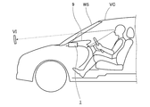
- FIG. 1B is a diagram schematically showing a state where the display forming apparatus 1 is mounted on a vehicle as seen from the side of the vehicle. Note that in FIG. 1A, illustration of some of the components of the display forming apparatus 1 is omitted.
- the X direction an example of the second direction
- the Y direction an example of the first direction
- the Z direction which are three directions orthogonal to each other, are defined in the right-handed system.
- the Z direction is the vertical direction
- the positive side is the upper side
- the negative side is the lower side.
- the display forming device 1 is for a head-up display, and is mounted in the instrument panel 9 of the vehicle.
- the display forming apparatus 1 may be mounted so that the Y direction in FIG. 1A substantially corresponds to the vehicle width direction.
- the display forming apparatus 1 includes a case 2, a TFT (Thin Film Transistor) panel unit 3 (an example of an image forming unit), mirrors 4 and 5, and a backlight unit 6.
- a TFT Thin Film Transistor
- Case 2 forms the housing of the display forming device 1.
- the case 2 is a lower case that forms a lower portion of the housing of the display forming apparatus 1.
- the case 2 is combined with an upper case (not shown in FIG. 1A).
- the case 2 is made of a material having high heat conductivity such as aluminum.
- the case 2 includes a heat dissipation portion 21 as shown in FIG. 1A.
- the heat dissipation portion 21 is formed on the outer surface (the surface exposed to the outside) of the case 2.
- the heat radiating portion 21 has a function of radiating the heat generated from the backlight unit 6.
- the heat dissipation part 21 radiates heat to the air flowing outside the case 2.
- the heat dissipation part 21 is formed integrally with the case 2.
- the heat dissipation part 21 may be formed by casting together with the case 2.
- the heat dissipation portion 21 may be formed separately from the case 2 and integrated with the case 2.
- the heat dissipation part 21 is in the form of a fin.
- the fins may have any shape, and may have a cylindrical shape or a straight fin shape as shown in FIG. 1A. Note that in FIG. 1A, the heat dissipation portion 21 is formed in such a manner that the straight fins extending in the vertical direction are arranged in the X direction.
- the TFT panel unit 3 is a display device that uses light from the backlight unit 6 as a backlight and emits image light according to a display image.
- the display image is arbitrary and may be, for example, an image representing navigation information, various vehicle information, or the like.
- the TFT panel unit 3 is fixed to the case 2.
- the TFT panel unit 3 is fastened with screws 90 at two positions on both sides in the X direction.
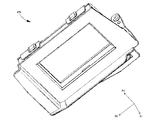
- FIG. 2 is a perspective view of the TFT panel unit 3 in a single item state
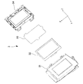
- FIG. 3 is an exploded perspective view of the TFT panel unit 3.
- the TFT panel unit 3 includes a TFT holder 31, a TFT panel 32, a diffusion sheet 33, and a TFT cover 34.
- the TFT holder 31 is fixed to the case 2 as described above.
- the TFT holder 31 holds the TFT panel 32.
- the TFT panel 32 is a dot matrix type TFT (Thin Film Transistor) panel or the like.
- the TFT panel 32 is provided so that the long side direction corresponds to the X direction.
- the TFT cover 34 is fitted and coupled to the TFT holder 31.
- the TFT panel 32 and the diffusion sheet 33 are held between the TFT cover 34 and the TFT holder 31 in the Y direction.
- the mirrors 4 and 5 reflect the image light emitted from the TFT panel unit 3, emit the image light from an emission port provided in an upper case (not shown), and the windshield glass WS of the vehicle VC (see FIG. 1B)).
- two mirrors 4 and 5 are provided, but the number of mirrors is arbitrary.
- the mirror 4 is a plane mirror and the mirror 5 is a concave mirror.
- the mirror 5 may be rotatably supported with respect to the case 2 so that the vertical position of the region of the windshield glass WS on which the image light strikes can be adjusted.
- the backlight unit 6 is provided behind the TFT panel unit 3 (negative side in the Y direction).
- the backlight unit 6 cooperates with the TFT panel unit 3 to generate image light.
- the backlight unit 6 is fixed to the case 2.
- FIG. 4 is a perspective view of the backlight unit 6 in a single item state
- FIG. 5 is an exploded perspective view of the backlight unit 6.
- the backlight unit 6 has a function of emitting light from the light source 8 to the TFT panel unit 3 and transmitting heat generated by the light source 8 to the heat dissipation portion 21.
- the backlight unit 6 includes a lens cover 61, a first lens spring 62, a condenser lens 63, a diffusion plate 64, a lens holder 65 (an example of a holding member), and a second lens spring 66 (of a leaf spring member).
- An example a lens array 67 (an example of a lens member), a substrate 68, and a heat conductive sheet 69.
- the lens cover 61 covers the front surface (the positive side in the Y direction) of the backlight unit 6.
- the lens cover 61 has an opening 611 through which the condenser lens 63 is exposed.
- the lens cover 61 is fitted and coupled to the lens holder 65.
- the lens cover 61 has claw portions 612 extending in the Y direction negative side at four corners, and the claw portions 612 are fitted and coupled to the lens holder 65.
- the first lens spring 62 is in the form of a leaf spring, and is provided between the lens cover 61 and the condenser lens 63 in the Y direction.
- the first lens springs 62 are provided as a pair in the vertical direction.
- Each of the first lens springs 62 is fixed to the upper and lower side surfaces of the lens cover 61.
- Each of the first lens springs 62 biases the condenser lens 63 together with the diffusion plate 64 toward the lens holder 65.
- the first lens spring 62 has a function of defining the positions of the condenser lens 63 and the diffusion plate 64 with respect to the lens holder 65 in the Y direction.
- the diffusion plate 64 and the condenser lens 63 diffuse and condense the light from the light source 8 that is incident through the lens array 67 onto the front surface (the positive side in the Y direction) of the backlight unit 6. Has the function of emitting light.
- the diffusion plate 64 is formed of, for example, a resin material having a light-transmitting property, and has a plate shape in which at least one surface is subjected to fine uneven processing.
- the diffuser plate 64 and the condenser lens 63 are held on the positive side in the Y direction of the lens holder 65.
- the diffusion plate 64 and the condenser lens 63 each have through holes 641 and 631 through which the pin portion 650 of the lens holder 65 passes, and the positions in the Z direction and the X direction with respect to the lens holder 65 are defined.
- the lens holder 65 holds the diffusion plate 64 and the condenser lens 63, and also holds the lens array 67.
- the lens holder 65 is fixed to the case 2.
- the backlight unit 6 is fixed to the case 2 by fixing the lens holder 65 to the case 2. A preferred example of a method for fixing the backlight unit 6 (lens holder 65) to the case 2 will be described later.
- the second lens spring 66 is in the form of a leaf spring and is fixed to the lens holder 65.
- the second lens spring 66 has a function of urging the lens array 67 toward the substrate 68.
- the second lens spring 66 further has a function of urging the heat conductive sheet 69 toward the substrate 68 (hereinafter, also referred to as “heat conductive sheet holding function”). Details of the configuration of the second lens spring 66 and details of the heat conductive sheet holding function of the second lens spring 66 will be described later.
- the lens array 67 is made of a translucent resin material, and is arranged so as to cover the positive side of the substrate 68 in the Y direction.
- the lens array 67 includes a collimator section 671 having a conical convex outer peripheral surface obtained by rotating a substantially parabolic wire.
- the lens array 67 is located opposite to the light source 8 mounted on the substrate 68, and transmits the light emitted from the light source 8 to the positive side in the Y direction.
- the outer shape of the lens array 67 is substantially the same as the outer shape of the TFT panel unit 3 (and the TFT panel 32) (rectangular shape whose long side is in the X direction).
- the substrate 68 is provided behind the lens array 67 (negative side in the Y direction).
- the light source 8 is mounted on the surface of the substrate 68 facing the lens array 67.
- the light source 8 is an LED (Light Emitting Diode).
- the arrangement method and the number of the light sources 8 are arbitrary.
- the light source 8 is provided so that the optical axis direction is perpendicular to the substrate 68. In this embodiment, the optical axis direction is the Y direction.
- the substrate 68 may be a glass epoxy substrate, a glass composite substrate, or the like.
- the substrate 68 may be positioned by the lens array 67 by being positioned by the lens holder 65.
- the heat conductive sheet 69 is a sheet-shaped member having heat conductivity.
- the heat conductive sheet 69 may be formed of a thermal sheet, TIM (Thermal Interface Material) or the like.
- the heat conductive sheet 69 may have a characteristic that the higher the pressure in the thickness direction, the smaller the thermal resistance. Note that this characteristic may be linear or non-linear.
- the heat transfer sheet 69 is sandwiched between the case 2 and the substrate 68 in the Y direction.
- the heat conductive sheet 69 is sandwiched on the side of the case 2 so as to come into contact with the surface 2a (FIG. 10) of the case 2.
- the heat transfer sheet 69 does not have adhesiveness on the surface. That is, the heat conductive sheet 69 does not have an adhesive layer on the surface. Therefore, the heat-transfer sheet 69 comes into contact (surface contact) with the other member (in this embodiment, the substrate 68 and the case 2) that comes into surface contact without being bonded. In addition, generally, the heat conductive sheet 69 having no adhesive layer is less expensive than the heat conductive sheet having an adhesive layer.
- FIG. 6 is a top view showing a state where the backlight unit 6 is assembled to the case 2
- FIG. 7 is a cross-sectional view taken along the line AA of FIG. 6, and
- FIG. 8 is a line of FIG.
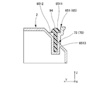
- FIG. 3 is a schematic cross-sectional view taken along the line BB.
- FIG. 9 is an explanatory diagram of a force generated by screw tightening.
- FIG. 10 is a perspective view for explaining a method of assembling the backlight unit 6 to the case 2.
- the backlight unit 6 is provided so as to be adjacent to the heat dissipation portion 21 of the case 2 in the Y direction, as shown in FIG.
- the surface 2a of the heat dissipation portion 21 on the Y direction positive side projects to the Y direction positive side.
- the surface 2a of the heat dissipation portion 21 is a surface with which the heat conductive sheet 69 is in surface contact.
- the case 2 has the recesses 2b on both sides of the heat dissipation portion 21 in the X direction.
- the recess 2b receives a second biasing portion 663 of the second lens spring 66, which will be described later.
- the backlight unit 6 is fixed to the case 2 at two places with screws 94 (an example of a fastening member).
- the screw 94 is tightened in the vertical direction (fastening direction) so as to move downward from the opening covered by the upper case toward the bottom surface of the case 2.
- it is easier to secure the work area and the workability of tightening the screw 94 is significantly improved, as compared with the case where the work area is tightened in a direction that advances in the XY plane.
- the case 2 has first screw receiving portions 70 (an example of a first mounting portion) on both sides of the mounting space of the backlight unit 6 in the X direction, and the lens holder 65 of the backlight unit 6 is
- the first screw fastening portion 651 (an example of a second mounting portion) is provided on both sides in the X direction, and the first screw fastening portion 651 is fastened to the first screw receiving portion 70 by the screw 94.
- the first screw fastening portion 651 has a seat portion 6511 that receives the lower surface of the head of the screw 94.
- the seat portion 6511 includes a notch 6512 that is open on the Y direction positive side. Therefore, the lens holder 65 can be displaced to the negative side in the Y direction with respect to the screw 94 until it is completely fastened.
- the surface 72 inclines in a manner (close to the heat dissipation portion 21). That is, when viewed from the Y direction positive side, the upper surface of the first screw receiving portion 70 is inclined downward.
- the inclination angle is arbitrary, but is, for example, about 45 degrees.
- the first screw fastening portion 651 has a lower surface 6513 along the surface 72 of the first screw receiving portion 70, as shown in FIG. Therefore, the lower surface 6513 is inclined downward when viewed from the Y direction positive side. Therefore, the first screw fastening portion 651 can be displaced along the surface with respect to the first screw receiving portion 70 until the lens holder 65 is completely fastened to the case 2 by the screw 94.
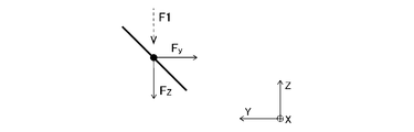
- the force F1 due to the screw tightening is a component (component force) Fy in the Y direction facing the negative side and a downward component (component force) Fz. Occurs in a manner that includes and.
- the component force Fy acts so as to displace the lens holder 65 with respect to the case 2 to the Y direction negative side. That is, when the tightening torque becomes relatively large during screw tightening, the lens holder 65 is displaced in the Y direction negative side with respect to the case 2 and obliquely downward.
- the lens holder 65 when the lens holder 65 is fastened to the case 2 with the screw 94, the lens holder 65 can be displaced to the negative side in the Y direction with respect to the case 2 by a slight amount.
- the displacement of the lens holder 65 to the negative side in the Y direction with respect to the case 2 at the time of such fastening has a function of appropriately compressing the heat conductive sheet 69 between the substrate 68 and the heat dissipation portion 21 of the case 2.
- the substrate 68 is provided so that the force in the Y direction is transmitted between the substrate 68 and the lens holder 65.
- the lens holder 65 has a portion 654 that abuts on the substrate 68 in the Y direction (hereinafter, also referred to as “abutting portion 654”).
- the substrate 68 and the lens holder 65 have a relationship in which the force in the Y direction is transmitted via the contact portion 654.
- the contact portions 654 may be provided at a plurality of positions on the substrate 68 so that the heat conductive sheet 69 is uniformly compressed in the plane.
- the lens holder 65 when the lens holder 65 is displaced to the Y direction negative side, the Y direction gap between the substrate 68 and the heat dissipation portion 21 of the case 2 (that is, the thickness of the heat conductive sheet 69) is reduced.
- the lens holder 65 may not have the contact portion 654, and the lens array 67 may have the similar contact portion 654.
- the substrate 68 is in a relationship in which the force in the Y direction is transmitted between the substrate 68 and the lens holder 65 via the lens array 67 and the second lens spring 66.
- the lens holder 65 when the lens holder 65 is displaced to the negative side in the Y direction, the gap in the Y direction between the substrate 68 and the heat dissipation portion 21 of the case 2 via the lens array 67 (that is, the thickness of the heat conductive sheet 69). Is reduced.
- a heat conductive sheet 69 is interposed between the substrate 68 and the heat dissipation portion 21 of the case 2. Therefore, the heat of the substrate 68 (heat generated by the light source 8) is transferred to the heat dissipation portion 21 via the heat transfer sheet 69 and is emitted to the outside.
- the heat conductive sheet 69 is in surface contact with both the substrate 68 and the heat dissipation portion 21 of the case 2 over the entire surface. Is usefully compressed in the Y direction toward the side surface of the case 2 (the side surface on the front surface 2a side).
- the lens holder 65 when the lens holder 65 is fastened to the case 2 with the screw 94, the lens holder 65 is displaced to the negative side in the Y direction with respect to the case 2 by a slight amount.
- the gap in the Y direction between the substrate 68 and the heat dissipation portion 21 of the case 2 (that is, the thickness of the heat conductive sheet 69) can be reduced by the reduction amount corresponding to the displacement via the lens array 67.
- the heat conductive sheet 69 between the substrate 68 and the heat dissipation portion 21 of the case 2 can be appropriately compressed.
- the lens holder 65 when the lens holder 65 is fastened to the case 2 with the screw 94, even when the screw 94 is fastened downward, the board 68 and the heat dissipation portion 21 of the case 2 are fastened.
- the heat conductive sheet 69 between them can be appropriately compressed. That is, when the lens holder 65 is fastened to the case 2 with screws, the heat conductive sheet between the substrate 68 and the heat dissipation portion 21 of the case 2 does not have to be tightened in the direction of moving to the negative side in the Y direction. 69 can be properly compressed.
- the lens holder 65 when the lens holder 65 is fastened to the case 2, it is possible to eliminate the screw that is fastened in the direction toward the negative side in the Y direction, so that the number of screws can be reduced and the work at the time of fastening You can improve your sex.
- workability if the screw is tightened in the direction of moving to the Y direction negative side, workability is not good from the viewpoint of work space.
- the screws 94 are fastened in the direction of moving downward, the workability is good because the space above the lens holder 65 is an open space.
- the gap in the Y direction between the substrate 68 and the heat dissipation portion 21 of the case 2 (that is, the thickness of the heat conductive sheet 69) may be excessively reduced. It is desirable to provide a stopper mechanism that mechanically prevents such excessive tightening.
- the stopper mechanism is arbitrary as long as it is a mechanism capable of restricting an excessive displacement (displacement exceeding the upper limit value) of the lens holder 65 toward the negative side in the Y direction with respect to the case 2.
- the case 2 has the second screw receiving portions 74 on both sides of the mounting space of the backlight unit 6 in the X direction, and the lens holder 65 of the backlight unit 6 has a center in the X direction.
- the screw passage 652 is provided on the upper side and on the negative side in the Y direction.
- the screw passing portion 652 is formed at a position corresponding to the second screw receiving portion 74.
- the first screw receiving portion 70 and the second screw receiving portion 74 have screw holes for receiving the screws 95.
- the screw passage portion 652 is in the form of a notch that is open on the Y direction negative side, and allows the shaft portion of the screw 95 to pass therethrough.
- the positional relationship in the Y direction between the screw passing portion 652 and the second screw receiving portion 74 is adapted so that the stopper mechanism described above functions properly. Specifically, when the tightening amount of the screw 94 is increased and the lens holder 65 is displaced in the Y direction negative side with respect to the case 2, the screw passage portion 652 of the lens holder 65 is moved to the Y direction with respect to the shaft portion of the screw 95. Abut in the direction. When the screw passage portion 652 of the lens holder 65 comes into contact with the shaft portion of the screw 95 in the Y direction, the lens holder 65 is less likely to be displaced in the Y direction negative side with respect to the case 2. Will work.
- a stopper mechanism may be separately provided, and the lens holder 65 may be fastened to the case 2 at a position corresponding to the second screw receiving portion 74.
- the number of screws as the fastening members is three, the screws to be fastened in the direction toward the negative side in the Y direction can be eliminated, so that workability at the time of fastening can be improved.
- the above-mentioned abutting portion 654 a protrusion for positioning which may be provided on the back surface (surface on the negative side in the Y direction) of the lens holder 65, or the like is used as the stopper mechanism. May function as.
- FIG. 11 is an explanatory view of the configuration of the back surface side (negative side in the Y direction) of the backlight unit 6, and is a perspective view showing a part of the display forming apparatus 1 excluding the case 2.
- FIG. 12 is a partial cross-sectional perspective view taken along the XY plane including the line CC of FIG. 11.
- FIG. 13 is a perspective view of the second lens spring 66 in a single product state.
- FIG. 14 is an explanatory diagram of the method of assembling the substrate 68
- FIG. 15 is an explanatory diagram of the method of assembling the heat conductive sheet 69.
- the substrate 68 is shown very schematically in FIGS. 14 and 15 for purposes of illustration.
- the second lens spring 66 has the function of urging the lens array 67 toward the substrate 68 and the function of holding the heat conductive sheet, as described above.
- the second lens springs 66 are provided on both side parts 658 of the lens holder 65 in the X direction. That is, the second lens springs 66 are located on both sides of the lens holder 65 in the X direction and form a pair.
- the respective second lens springs 66 on both sides in the X direction are symmetrical in the X direction.
- one of the second lens springs 66 will be described.
- the second lens spring 66 includes a fixing portion 661, a first urging portion 662 (an example of a first portion), a second urging portion 663 (an example of a second portion), and a protrusion. Section 664.
- the fixing portion 661 is a portion fixed to the lens holder 65.
- the fixed portion 661 includes a pair of holding portions 6611 that holds the side portion 658 of the lens holder 65, and a fitting portion 6612 that fits into the convex portion 6581 of the side portion 658 of the lens holder 65.
- the first urging unit 662 urges the lens array 67 toward the substrate 68.
- the first biasing portion 662 is formed so as to be continuous with the fixed portion 661.
- the first biasing portion 662 extends in the X direction and is elastically deformed by receiving a force from the lens array 67 toward the positive side in the Y direction.
- the first urging portions 662 are provided at two upper and lower positions centering on the vertical center of the side portion 658 of the lens holder 65. In this case, the first biasing portion 662 can bias the lens array 67 toward the substrate 68 substantially vertically. This is because the vertical center of the lens holder 65 and the vertical center of the lens array 67 substantially coincide with each other.
- the second urging unit 663 realizes the heat conductive sheet holding function by urging the heat conductive sheet 69 toward the substrate 68.
- the second biasing portion 663 is formed so as to be continuous with the fixed portion 661.
- the second urging portion 663 bends at a position further away from the lens array 67 than the heat conductive sheet 69 in the Y direction (hereinafter, also referred to as “bending position”, see P1 in FIG. 12) (an example of the first position). After that, it extends toward a position (hereinafter, also referred to as “contact position”, see P2 in FIG. 12) in contact with the heat conductive sheet 69 (an example of the second position). Therefore, the second biasing portion 663 includes a portion extending to the Y direction negative side with respect to the heat conductive sheet 69, and a part of the portion is located inside the recess 2b (see FIG. 10) of the case 2.
- the second biasing portion 663 has an inclined surface 6632.
- the inclined surface 6632 is formed between the bending position (see P1 in FIG. 12) and the contact position (see P2 in FIG. 12).
- the inclined surface 6632 is closer to the center of the lens array 67 in the X direction in the contact position (see P2 in FIG. 12) than in the bent position (see P1 in FIG. 12) when viewed in the Z direction (up and down direction). In an aspect, it tilts.
- the inclined surface 6632 may be formed entirely between the bent position (see P1 in FIG. 12) and the contact position (see P2 in FIG. 12).
- the inclined surface 6632 may be formed only in a part between the bending position (see P1 in FIG. 12) and the contact position (see P2 in FIG. 12). By having such an inclined surface 6632, the assembly of the substrate 68 becomes easy.
- the second lens spring 66 and the like are attached to the lens holder 65, when the substrate 68 is attached in the Y direction from the Y direction negative side as shown by an arrow R1 in FIG. Then, it is possible to move to the positive side in the Y direction along the inclined surface 6632. That is, the second lens spring 66 can be elastically deformed in such a manner that the substrate 68 is guided to the positive side in the Y direction. At this time, the second urging portion 663 elastically deforms in the direction in which the bending angle becomes narrower (see arrow R2 in FIG. 14), and allows the substrate 68 to further advance (assemble) to the Y direction positive side.
- the substrate 68 reaches the Y direction positive side of the second urging portion 663, and the second urging portion 663 restores in a mode in which the bending angle returns to the original state.
- the second urging unit 663 is still urging the substrate 68 toward the lens array 67.
- the second biasing portion 663 contacts the substrate 68 without biasing the substrate 68 toward the lens array 67. It may be just in the state of being.
- the protrusion 664 is formed on the surface of the second biasing portion 663 on the negative side in the Y direction (the side far from the lens array 67).
- the protrusion 664 is formed so as to be continuous with the second biasing portion 663.
- the protrusion 664 has a function of improving the assembling property when the heat transfer sheet 69 is mounted on the substrate 68.
- the heat conductive sheet 69 is assembled after the substrate 68 is assembled to the lens holder 65 as described above, but the second urging portion 663 places the heat conductive sheet 69 on the substrate 68. It extends in a manner to overlap the surface. Therefore, the second urging portion 663 becomes an obstacle when the heat conductive sheet 69 is assembled.
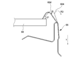
- the second urging portion 663 is temporarily elastically deformed to the Y direction negative side (see the dotted line in FIG. 15), and the substrate 68 and the second attaching member 663 are attached. It is necessary to form a gap ⁇ 1 (see FIG. 15) into which the heat conductive sheet 69 is inserted, between the biasing portion 663.
- the protrusion 664 is preferably inclined in the same direction as the inclined surface 6632 of the second biasing portion 663 when viewed in the Z direction. That is, the protrusion 664 is closer to the center of the lens array 67 in the X direction at the root position (see P3 in FIG. 13) on the second biasing portion 663 side than in the tip position (see P4 in FIG. 13). It inclines and extends. In this case, it becomes easy to temporarily apply elastic force to the protrusion 664 to elastically deform the second urging portion 663 to the Y direction negative side.
- the backlight unit 6 in the assembled state in which the heat conductive sheet 69 is held by the second lens spring 66 can be configured.
- the heat dissipation portion 21 is formed as a part of the case 2 as in the present embodiment
- the heat dissipation portion 21 of the case 2 and the substrate 68 before the backlight unit 6 is assembled to the case 2, the heat dissipation portion 21 of the case 2 and the substrate 68. It is not possible to hold the heat conductive sheet 69 between them.
- the heat conductive sheet 69 is provided with adhesiveness, the heat dissipation portion 21 or the substrate. It is also possible to assemble the backlight unit 6 to the case 2 with the heat transfer sheet 69 attached to 68.
- using the heat conductive sheet 69 having such adhesiveness is disadvantageous in terms of cost and the like.
- the second lens spring 66 includes the second urging portion 663, so that the backlight unit in an assembled state in which the heat conductive sheet 69 is held by the second lens spring 66. 6 can be attached to the case 2. That is, it is possible to properly assemble the heat conductive sheet 69 without imparting tackiness to the heat conductive sheet 69. As a result, the cost of the heat conductive sheet 69 can be reduced.
- the lens holder 65 has the notch 6512 in the first screw fastening portion 651 so that the lens holder 65 can be displaced in the Y direction positive side with respect to the case 2, but instead of the notch 6512, Y An elongated hole whose direction is the longitudinal direction may be formed.
- the heat conductive sheet 69 is provided between the substrate 68 and the heat dissipation portion 21, but the heat conductive sheet 69 may be omitted.
- the lens holder 65 may be fixed to the case 2 so that the substrate 68 directly contacts the heat dissipation portion 21 (the surface 2a of the case 2).
- the method of fixing the lens holder 65 to the case 2 may be the same as that in the above-described embodiment.
Landscapes
- Engineering & Computer Science (AREA)
- General Engineering & Computer Science (AREA)
- Physics & Mathematics (AREA)
- General Physics & Mathematics (AREA)
- Optics & Photonics (AREA)
- Arrangement Of Elements, Cooling, Sealing, Or The Like Of Lighting Devices (AREA)
- Securing Globes, Refractors, Reflectors Or The Like (AREA)
- Planar Illumination Modules (AREA)
- Liquid Crystal (AREA)
Abstract
ヒートシンクのような放熱部位がケースの一部として形成される構成において、良好な作業性の組み付けによって光源の熱が放熱部位に伝熱されるようにする。 放熱部位を含む筐体と、光源が実装される基板と、光源から放射された光が透過するレンズ部材と、締結部材により筐体に固定され、レンズ部材を保持する保持部材とを備え、基板は、保持部材との間で第1方向での力が伝わり合う関係で設けられ、筐体は、第1取付部を有し、第1取付部は、第1方向と締結部材の締結方向とに交差する第2方向に視て、第1方向で放熱部位に近くなるほど締結方向の前進側に向かう態様で表面が傾斜し、保持部材は、第1取付部の表面に沿う表面を有する第2取付部を有し、保持部材は、第2取付部に形成された穴又は切り欠きを通る締結部材を介して第1取付部に締結される、表示形成装置が開示される。
Description
本開示は、表示形成装置に関する。
光源が実装される基板を伝熱性シートを介してヒートシンクに熱的に接続した表示形成装置用の照明装置が知られている。
上記のような従来技術では、ヒートシンクは、照明装置の一部を形成し、照明装置が収容されるケースとは別体であるので、光源が実装される基板をヒートシンクに締結した状態のサブアセンブリを容易に形成できる。
しかしながら、ヒートシンクのような放熱部位がケースの一部として形成される構成では、光源が実装される基板を、ケース内面に向けて内側から外側に締結する構成となるので、作業性が良好でない。
そこで、1つの側面では、本開示の表示形成装置は、ヒートシンクのような放熱部位がケースの一部として形成される構成において、良好な作業性の組み付けによって光源の熱が放熱部位に伝熱されるようにすることを目的とする。
1つの側面では、放熱部位を含む筐体と、
光源が実装される基板と、
前記光源から放射された光が透過するレンズ部材と、
締結部材により前記筐体に固定され、前記レンズ部材を保持する保持部材とを備え、
前記基板は、前記保持部材との間で第1方向での力が伝わり合う関係で設けられ、
前記筐体は、第1取付部を有し、
前記第1取付部は、前記第1方向に交差しかつ前記締結部材の締結方向に交差する第2方向に視て、前記第1方向で前記放熱部位に近くなるほど前記締結方向の前進側に向かう態様で表面が傾斜し、
前記保持部材は、前記第1取付部の前記表面に沿う表面を有する第2取付部を有し、
前記保持部材は、前記第2取付部に形成された穴又は切り欠きを通る前記締結部材を介して前記第1取付部に締結される、表示形成装置が提供される。
光源が実装される基板と、
前記光源から放射された光が透過するレンズ部材と、
締結部材により前記筐体に固定され、前記レンズ部材を保持する保持部材とを備え、
前記基板は、前記保持部材との間で第1方向での力が伝わり合う関係で設けられ、
前記筐体は、第1取付部を有し、
前記第1取付部は、前記第1方向に交差しかつ前記締結部材の締結方向に交差する第2方向に視て、前記第1方向で前記放熱部位に近くなるほど前記締結方向の前進側に向かう態様で表面が傾斜し、
前記保持部材は、前記第1取付部の前記表面に沿う表面を有する第2取付部を有し、
前記保持部材は、前記第2取付部に形成された穴又は切り欠きを通る前記締結部材を介して前記第1取付部に締結される、表示形成装置が提供される。
1つの側面では、本開示によれば、ヒートシンクのような放熱部位がケースの一部として形成される構成において、良好な作業性の組み付けによって光源の熱が放熱部位に伝熱されるようにすることが可能となる。
以下、添付図面を参照しながら各実施例について詳細に説明する。なお、図1A等では、見易さのために、複数存在する同一属性の部位には、一部のみしか参照符号が付されていない場合がある。
[表示形成装置の構成]
図1Aは、一実施例による表示形成装置1の内部構成を上側から示す斜視図である。図1Bは、表示形成装置1の車両搭載状態を車両側方視で概略的に示す図である。なお、図1Aでは、表示形成装置1の一部の構成要素の図示は省略されている。図1Aには、右手系で、互いに直交する3方向であるX方向(第2方向の一例)、Y方向(第1方向の一例)、及びZ方向が定義されている。以下では、形式上、Z方向を上下方向とし、正側を上側とし、負側を下側とする。
図1Aは、一実施例による表示形成装置1の内部構成を上側から示す斜視図である。図1Bは、表示形成装置1の車両搭載状態を車両側方視で概略的に示す図である。なお、図1Aでは、表示形成装置1の一部の構成要素の図示は省略されている。図1Aには、右手系で、互いに直交する3方向であるX方向(第2方向の一例)、Y方向(第1方向の一例)、及びZ方向が定義されている。以下では、形式上、Z方向を上下方向とし、正側を上側とし、負側を下側とする。
表示形成装置1は、ヘッドアップディスプレイ用であり、車両のインストルメントパネル9内に搭載される。表示形成装置1は、図1AのY方向が車幅方向に略対応する向きで搭載されてよい。
表示形成装置1は、ケース2と、TFT(Thin Film Transistor)パネルユニット3(画像形成ユニットの一例)と、ミラー4,5と、バックライトユニット6とを含む。
ケース2は、表示形成装置1の筐体を形成する。ケース2は、表示形成装置1の筐体の下部を形成するロアケースである。なお、ケース2は、図1Aでは図示が省略されたアッパーケースと結合される。
ケース2は、アルミ等のような伝熱性の高い材料により形成される。ケース2は、図1Aに示すように、放熱部位21を含む。放熱部位21は、ケース2の外側表面(外部に露出する表面)に形成される。放熱部位21は、バックライトユニット6から発生する熱を放熱する機能を有する。放熱部位21は、ケース2外を流れる空気に熱を放出する。
放熱部位21は、ケース2と一体に形成される。例えば、放熱部位21は、ケース2とともに鋳造により形成されてもよい。ただし、放熱部位21は、ケース2とは別に形成され、ケース2に一体化されてもよい。
放熱部位21は、フィンの形態である。フィンの形態は任意であり、円柱状の形態であってもよいし、図1Aに示すように、ストレートフィンの形態であってもよい。なお、図1Aでは、放熱部位21は、上下方向に延在するストレートフィンがX方向に並ぶ態様で形成される。
TFTパネルユニット3は、バックライトユニット6からの光をバックライトとして利用して、表示画像に応じた画像光を出射する表示器である。なお、表示画像は、任意であり、例えばナビゲーション情報や各種の車両情報等を表す画像であってよい。
TFTパネルユニット3は、ケース2に固定される。例えば、TFTパネルユニット3は、図1Aに示すように、X方向の両側の2箇所でネジ90により締結される。
図2は、TFTパネルユニット3の単品状態の斜視図であり、図3は、TFTパネルユニット3の分解斜視図である。
TFTパネルユニット3は、TFTホルダ31と、TFTパネル32と、拡散シート33と、TFTカバー34とを含む。TFTホルダ31は、上述のようにケース2に固定される。TFTホルダ31は、TFTパネル32を保持する。TFTパネル32は、ドットマトリクス型のTFT(Thin Film Transistor)パネル等である。TFTパネル32は、長辺方向がX方向に対応する向きで設けられる。TFTカバー34は、TFTホルダ31に嵌合結合される。Y方向でTFTカバー34とTFTホルダ31の間には、TFTパネル32及び拡散シート33が保持される。
ミラー4,5は、TFTパネルユニット3から出射される画像光を反射して、アッパーケース(図示せず)に設けられた出射口から画像光を出射させ、車両VCのウインドシールドガラスWS(図1B参照)に向かわせる。本実施例では、2つのミラー4、5が設けられるが、ミラーの数は任意である。本実施例では、一例として、ミラー4は、平面ミラーであり、ミラー5は、凹面ミラーである。ミラー5は、ウインドシールドガラスWSにおける画像光が当たる領域の上下位置が調整可能となるように、ケース2に対して回転可能に支持されてよい。
なお、ウインドシールドガラスWSに画像光が照射されると、図1Bに示すように、車両VCを運転する運転者にとっては、ウインドシールドガラスWSよりも前方に、当該照射によって得られた表示像(虚像表示)VIが見える。これにより、運転者は、前方風景と重畳させて表示像VIを視認でき、視線移動の少ない態様で車両情報等を把握でき、利便性及び安全性が向上する。
バックライトユニット6は、TFTパネルユニット3の背後(Y方向の負側)に設けられる。バックライトユニット6は、TFTパネルユニット3と協動して、画像光を生成する。バックライトユニット6は、ケース2に固定される。
図4は、バックライトユニット6の単品状態の斜視図であり、図5は、バックライトユニット6の分解斜視図である。
バックライトユニット6は、光源8からの光をTFTパネルユニット3へと出射するとともに、光源8で発生する熱を放熱部位21に伝達する機能を有する。
バックライトユニット6は、レンズカバー61と、第1レンズスプリング62と、集光レンズ63と、拡散板64と、レンズホルダ65(保持部材の一例)と、第2レンズスプリング66(板ばね部材の一例)と、レンズアレイ67(レンズ部材の一例)と、基板68と、伝熱性シート69とを含む。
レンズカバー61は、バックライトユニット6の前面(Y方向の正側)を覆う。レンズカバー61は、集光レンズ63が露出する開口部611を有する。レンズカバー61は、レンズホルダ65に嵌合結合される。本実施例では、一例として、レンズカバー61は、4隅に、Y方向負側に延びる爪部612を有し、爪部612によりレンズホルダ65に嵌合結合される。
第1レンズスプリング62は、板ばねの形態であり、Y方向でレンズカバー61と集光レンズ63の間に設けられる。第1レンズスプリング62は、上下方向で対に設けられる。第1レンズスプリング62のそれぞれは、レンズカバー61の上辺及び下辺側の側面に固定される。第1レンズスプリング62のそれぞれは、集光レンズ63を拡散板64とともに、レンズホルダ65に向けて付勢する。このように、第1レンズスプリング62は、レンズホルダ65に対する集光レンズ63及び拡散板64のY方向の位置を規定する機能を有する。
拡散板64及び集光レンズ63は、光源8からの光であってレンズアレイ67を通って入射する光を、バックライトユニット6の前面(Y方向の正側)へと、拡散及び集光して出射する機能を有する。拡散板64は、例えば、透光性を有する樹脂材料から形成され、少なくとも一面に微細な凹凸加工が施された板状である。
拡散板64及び集光レンズ63は、レンズホルダ65のY方向の正側に保持される。例えば、拡散板64及び集光レンズ63は、それぞれ、レンズホルダ65のピン部650が通る貫通穴641,631を有し、レンズホルダ65に対してZ方向及びX方向の位置が規定される。
レンズホルダ65は、拡散板64及び集光レンズ63を保持するとともに、レンズアレイ67を保持する。レンズホルダ65は、ケース2に固定される。バックライトユニット6は、レンズホルダ65がケース2に固定されることで、ケース2に固定される。ケース2に対するバックライトユニット6(レンズホルダ65)の固定方法の好ましい例は、後述する。
第2レンズスプリング66は、板ばねの形態であり、レンズホルダ65に固定される。第2レンズスプリング66は、レンズアレイ67を基板68に向けて付勢する機能を有する。また、本実施例では、第2レンズスプリング66は、更に、伝熱性シート69を基板68に向けて付勢する機能(以下、「伝熱性シート保持機能」とも称する)を有する。第2レンズスプリング66の構成の詳細と、第2レンズスプリング66による伝熱性シート保持機能の詳細は、後述する。
レンズアレイ67は、透光性の樹脂材料から形成され、基板68のY方向の正側を覆うように配置されている。レンズアレイ67は、略放物断線を回転して得られる円錐凸形状の外周面を有するコリメータ部671を含む。レンズアレイ67は、基板68に実装された光源8に対向して位置し、光源8から放射された光をY方向の正側へと透過させる。なお、レンズアレイ67の外形は、TFTパネルユニット3(及びTFTパネル32)の外形と略同様の矩形(X方向を長辺方向とする矩形)である。
基板68は、レンズアレイ67の背後(Y方向の負側)に設けられる。基板68は、レンズアレイ67に対向する側の表面に、光源8が実装される。光源8は、LED(Light Emitting Diode)である。光源8の配列方法や数は任意である。光源8は、光軸方向が基板68に対して垂直になるように設けられる。なお、本実施例では、光軸方向は、Y方向である。基板68は、ガラスエポキシ基板やガラスコンポジット基板等であってよい。なお、基板68は、レンズホルダ65により位置決めされることで、レンズアレイ67により位置決めされてもよい。
伝熱性シート69は、伝熱性を有するシート状の部材である。伝熱性シート69は、サーマルシート、TIM(Thermal Interface Material)又はその類により形成されてよい。伝熱性シート69は、厚み方向の圧力が高いほど熱抵抗が小さくなる特性を有してもよい。なお、この特性は、線形であってもよいし、非線形であってもよい。
伝熱性シート69は、Y方向でケース2と基板68との間に挟持される。特に、伝熱性シート69は、ケース2側ではケース2の表面2a(図10)に当接する態様で、挟持される。
伝熱性シート69は、表面に粘着性を有さない。すなわち、伝熱性シート69は、表面に粘着層を有さない。従って、伝熱性シート69は、面接触する相手方の部材(本実施例では、基板68とケース2)に対して接着しない態様で当接(面接触)する。なお、一般的に、粘着層を有さない伝熱性シート69は、粘着層を有する伝熱性シートよりも安価である。
[ケースに対するバックライトユニット(レンズホルダ)の固定方法]
次に、図6~図10を参照して、ケース2に対するバックライトユニット6(レンズホルダ65)の固定方法の好ましい例と、本実施例によるバックライトユニット6の放熱原理について説明する。
次に、図6~図10を参照して、ケース2に対するバックライトユニット6(レンズホルダ65)の固定方法の好ましい例と、本実施例によるバックライトユニット6の放熱原理について説明する。
図6は、ケース2にバックライトユニット6が組み付けられた状態を示す上面図であり、図7は、図6のラインA-Aに沿った断面図であり、図8は、図6のラインB-Bに沿った模式的な断面図である。図9は、ビス締めにより発生する力の説明図である。図10は、ケース2へのバックライトユニット6の組み付け方法を説明するための斜視図である。
バックライトユニット6は、図10に示すように、Y方向でケース2の放熱部位21に隣接する態様で設けられる。なお、本実施例では、一例として、ケース2は、放熱部位21のY方向正側の表面2aがY方向正側に突出する。放熱部位21の表面2aは、伝熱性シート69が面接触する表面である。また、本実施例では、一例として、ケース2は、X方向で放熱部位21の両側に凹部2bを有する。凹部2bは、後述する第2レンズスプリング66の第2付勢部663を受け入れる。
バックライトユニット6は、図10に示すように、ケース2に対してビス94(締結部材の一例)により2箇所で固定される。ビス94は、上下方向(締結方向)で、アッパーケースで覆われる開口からケース2の底面に向く下側に進む向きで、締め込まれる。この場合、XY平面内の方向に進む向きで締め込まれる場合に比べて、作業領域の確保が容易であり、ビス94の締め込みの作業性が大幅に向上する。
具体的には、ケース2は、バックライトユニット6の搭載スペースのX方向の両側に第1ビス受部70(第1取付部の一例)を有し、バックライトユニット6のレンズホルダ65は、X方向の両側に第1ビス締結部651(第2取付部の一例)を有し、第1ビス受部70に第1ビス締結部651がビス94により締結される。
第1ビス締結部651は、ビス94の頭部の下面を受ける座部6511を有する。座部6511は、Y方向正側が開口した切り欠き6512を備える。従って、レンズホルダ65は、完全に締結されるまでは、ビス94に対してY方向の負側に変位可能である。
第1ビス受部70は、図8に示すように、X方向(レンズアレイ67の長辺方向)に視て、下方に向かうほどY方向(=光源8の光軸方向)負側に向かう態様(放熱部位21に近くなる態様)で表面72が傾斜する。すなわち、Y方向正側から見て、第1ビス受部70の上側表面は、下方に傾斜する。なお、傾斜角度は、任意であるが、例えば45度程度である。
第1ビス締結部651は、図8に示すように、第1ビス受部70の表面72に沿う下面6513を有する。従って、下面6513は、Y方向正側から見て、下方に傾斜する。従って、ビス94によりレンズホルダ65がケース2に完全に締結されるまでは、第1ビス締結部651は、第1ビス受部70に対して面沿いに変位可能である。
従って、図9に模式的に示すように、ビス94により締結される際、ビス締めによる力F1が、負側に向くY方向の成分(分力)Fyと、下向きの成分(分力)Fzとを含む態様で発生する。このとき、分力Fyは、ケース2に対してレンズホルダ65をY方向負側に変位させるように作用する。すなわち、ビス締めの際に、締め込みトルクが比較的大きくなると、レンズホルダ65はケース2に対してY方向負側かつ下方へと斜め方向に変位する。
このようにして、本実施例では、ケース2に対してレンズホルダ65をビス94で締結する際に、ケース2に対してレンズホルダ65がY方向負側に若干量だけ変位させることができる。このような締結の際のケース2に対するレンズホルダ65のY方向負側への変位は、基板68とケース2の放熱部位21との間の伝熱性シート69を適切に圧縮させる機能を果たす。
本実施例では、基板68は、レンズホルダ65との間でY方向の力が伝わり合う態様で設けられている。具体的には、図7に示すように、レンズホルダ65は、基板68にY方向で当接する部位654(以下、「当接部位654」とも称する)を有する。この場合、基板68は、レンズホルダ65との間で、当接部位654を介してY方向の力が伝わり合う関係である。なお、当接部位654は、伝熱性シート69が面内で均等に圧縮するように、基板68に複数箇所設けられてもよい。これにより、レンズホルダ65がY方向負側に変位すると、基板68とケース2の放熱部位21との間のY方向の隙間(すなわち伝熱性シート69の厚み)が低減される関係となる。なお、変形例では、レンズホルダ65は、当接部位654を有さず、レンズアレイ67が同様の当接部位654を有してもよい。この場合も、基板68は、レンズホルダ65との間で、レンズアレイ67及び第2レンズスプリング66を介してY方向の力が伝わり合う関係である。従って、この場合も、レンズホルダ65がY方向負側に変位すると、レンズアレイ67を介して基板68とケース2の放熱部位21との間のY方向の隙間(すなわち伝熱性シート69の厚み)が低減される関係となる。
ここで、図7に示すように、基板68とケース2の放熱部位21との間には伝熱性シート69が介在する。従って、基板68の熱(光源8で発生する熱)は、伝熱性シート69を介して放熱部位21に伝達し、外部に放出される。このような熱の伝達経路を適切に確立するためには、伝熱性シート69が基板68とケース2の放熱部位21の双方に表面全体にわたって面接触していることが有用であり、このためには、ケース2の側面(表面2a側の側面)に向くY方向に圧縮されていることが有用である。
そして、本実施例では、上述のように、ケース2に対してレンズホルダ65をビス94で締結する際に、ケース2に対してレンズホルダ65がY方向負側に若干量だけ変位するので、当該変位に応じた低減量だけ、レンズアレイ67を介して基板68とケース2の放熱部位21との間のY方向の隙間(すなわち伝熱性シート69の厚み)を低減できる。これにより、基板68とケース2の放熱部位21との間の伝熱性シート69を適切に圧縮させることができる。
このようにして、本実施例では、ケース2に対してレンズホルダ65をビス94で締結する際に、ビス94を下方に進む向きで締結する場合でも、基板68とケース2の放熱部位21との間の伝熱性シート69を適切に圧縮させることができる。すなわち、ケース2に対してレンズホルダ65をビスで締結する際に、ビスをY方向負側に進む向きに締め込まなくても、基板68とケース2の放熱部位21との間の伝熱性シート69を適切に圧縮させることができる。この結果、本実施例では、ケース2に対してレンズホルダ65を締結する場合に、Y方向負側に進む向きに締め込むビスを廃止できるので、ビスの点数を低減するとともに、締結時の作業性を高めることができる。なお、作業性に関しては、ビスをY方向負側に進む向きに締め込む場合は、作業スペースの観点から作業性が良好でない。ビス94を下方に進む向きで締結する場合、レンズホルダ65の上方は開放された空間であるので、作業性が良好である。
ところで、ビス94の締め込み量が過剰となると、基板68とケース2の放熱部位21との間のY方向の隙間(すなわち伝熱性シート69の厚み)が過剰に低減する可能性があるので、かかる過剰な締め込みを機械的に防止するストッパ機構を備えることが望ましい。
かかるストッパ機構は、ケース2に対してレンズホルダ65のY方向負側への過剰な変位(上限値を超えるような変位)を規制できる機構であれば、任意である。
本実施例では、一例として、ケース2は、バックライトユニット6の搭載スペースのX方向の両側に第2ビス受部74を有し、バックライトユニット6のレンズホルダ65は、X方向の中央、上側かつY方向負側にビス通過部652とを有する。ビス通過部652は、第2ビス受部74に対応した位置に形成される。第1ビス受部70及び第2ビス受部74には、ビス95を受け入れるビス穴が形成される。ビス通過部652は、Y方向負側が開口する切り欠きの形態であり、ビス95の軸部が通過可能である。ビス通過部652と第2ビス受部74とのY方向の位置関係は、上述のストッパ機構が適切に機能するように適合される。具体的には、ビス94の締め込み量が増加してレンズホルダ65がケース2に対してY方向負側に変位すると、ビス95の軸部に対してレンズホルダ65のビス通過部652がY方向に当接する。ビス95の軸部に対してレンズホルダ65のビス通過部652がY方向に当接すると、レンズホルダ65がケース2に対してY方向負側に変位しがたくなるので、この位置でストッパ機構が機能することになる。
なお、変形例では、ストッパ機構を別に設け、第2ビス受部74に対応する箇所においても、ケース2に対してレンズホルダ65が締結されてもよい。この場合でも、締結部材としてのビスの本数は3本となるものの、Y方向負側に進む向きに締め込むビスを廃止できるので、締結時の作業性を高めることができる。
また、別の変形例では、他のストッパ機構として、上述した当接部位654や、レンズホルダ65の背面(Y方向負側の表面)等に設けられてよい位置決め用の突起等が、ストッパ機構として機能してもよい。
[第2レンズスプリングの構成及び伝熱性シート保持機能の詳細]
次に、第2レンズスプリング66の構成と、第2レンズスプリング66による伝熱性シート保持機能の詳細について説明する。
次に、第2レンズスプリング66の構成と、第2レンズスプリング66による伝熱性シート保持機能の詳細について説明する。
図11は、バックライトユニット6の背面側(Y方向負側)の構成の説明図であり、ケース2を除く表示形成装置1の一部を示す斜視図である。図12は、図11のラインC―Cを含むXY平面で切断した際の一部の断面斜視図である。図13は、第2レンズスプリング66の単品状態の斜視図である。図14は、基板68の組み付け方法の説明図であり、図15は、伝熱性シート69の組み付け方法の説明図である。図14及び図15には、説明用に、基板68が非常に模式的に示されている。
第2レンズスプリング66は、上述のように、レンズアレイ67を基板68に向けて付勢する機能と、伝熱性シート保持機能とを有する。第2レンズスプリング66は、図11に示すように、X方向でレンズホルダ65の両側部658にそれぞれ設けられる。すなわち、第2レンズスプリング66は、レンズホルダ65のX方向の両側に位置し、対をなす。X方向の両側のそれぞれの第2レンズスプリング66は、X方向で対称な構成である。以下では、特に言及しない限り、一方の第2レンズスプリング66について説明する。
第2レンズスプリング66は、図13に示すように、固定部661と、第1付勢部662(第1部位の一例)と、第2付勢部663(第2部位の一例)と、突起部664とを含む。
固定部661は、レンズホルダ65に固定される部位である。固定部661は、レンズホルダ65の側部658を挟持する対の挟持部6611と、レンズホルダ65の側部658の凸部6581に嵌合する嵌合部6612とを有する。
第1付勢部662は、レンズアレイ67を基板68に向けて付勢する。第1付勢部662は、固定部661から連続する態様で形成される。第1付勢部662は、X方向に延在し、レンズアレイ67からY方向の正側に向かう力を受けて弾性変形する。第1付勢部662は、レンズホルダ65の側部658における上下方向の中心を中心とする上下2カ所に設けられる。この場合、第1付勢部662は、レンズアレイ67を基板68に向けて上下略均等に付勢できる。これは、レンズホルダ65の上下方向の中心とレンズアレイ67の上下方向の中心とは略一致するためである。
第2付勢部663は、伝熱性シート69を基板68に向けて付勢することで、伝熱性シート保持機能を実現する。第2付勢部663は、固定部661から連続する態様で形成される。第2付勢部663は、Y方向で伝熱性シート69よりもレンズアレイ67から離れた位置(以下、「屈曲位置」とも称する、図12のP1参照)(第1位置の一例)で屈曲してから伝熱性シート69に当接する位置(以下、「当接位置」とも称する、図12のP2参照)(第2位置の一例)に向かうように延在する。従って、第2付勢部663は、伝熱性シート69よりもY方向負側に延在する部位を含み、当該部位の一部が、ケース2の凹部2b(図10参照)内に位置する。
第2付勢部663は、傾斜面6632を有する。傾斜面6632は、図12に示すように、屈曲位置(図12のP1参照)と当接位置(図12のP2参照)の間に形成される。傾斜面6632は、Z方向(上下方向)に視て、屈曲位置(図12のP1参照)よりも当接位置(図12のP2参照)の方がX方向でレンズアレイ67の中心に近くなる態様で、傾斜する。傾斜面6632は、図12に示すように、屈曲位置(図12のP1参照)と当接位置(図12のP2参照)の間の全体にわたって形成されてもよい。ただし、変形例では、傾斜面6632は、屈曲位置(図12のP1参照)と当接位置(図12のP2参照)の間の一部のみに形成されてもよい。このような傾斜面6632を有することで、基板68の組み付けが容易となる。
具体的には、レンズホルダ65に第2レンズスプリング66等を組み付けた後、図14に矢印R1で示すように、基板68をY方向にY方向負側から取り付ける際、基板68は傾斜面6632に当たり、傾斜面6632に沿ってY方向正側に進むことができる。すなわち、第2レンズスプリング66は、基板68をY方向正側へと誘い込む態様で、弾性変形できる。このとき、第2付勢部663は、屈曲角度が狭くなる方向に弾性変形し(図14の矢印R2参照)、基板68のY方向正側への更なる進行(組み付け)を可能とする。そして、最終的には、基板68は、第2付勢部663よりもY方向正側に至り、第2付勢部663は屈曲角度が元に戻る態様で復元する。ただし、この状態(基板68の組み付けが完了した状態)でも、第2付勢部663は、基板68をレンズアレイ67に向けて付勢している状態である。あるいは、基板68の組み付けが完了した状態(伝熱性シート69の組み付け前の状態)では、第2付勢部663は、基板68をレンズアレイ67に向けて付勢せずに基板68に接触しているだけの状態であってもよい。
突起部664は、第2付勢部663にY方向負側(レンズアレイ67から遠い側)の表面に形成される。突起部664は、第2付勢部663から連続する態様で形成される。
突起部664は、基板68上に伝熱性シート69を載置するための組み付けの際に、組み付け性を良好にする機能を有する。具体的には、伝熱性シート69は、上述のようにレンズホルダ65に基板68を組み付けた後に、組み付けられることになるが、第2付勢部663が基板68における伝熱性シート69の載置面に重なる態様で延在する。このため、伝熱性シート69の組み付けの際に第2付勢部663が邪魔になる。換言すると、伝熱性シート69を基板68上に組み付けるためには、第2付勢部663を一時的にY方向負側に弾性変形させて(図15の点線参照)、基板68と第2付勢部663との間に、伝熱性シート69が入る隙間Δ1(図15参照)を形成する必要がある。
この点、突起部664を有する場合は、図15に矢印R3に示すように、突起部664に力を加えて第2付勢部663を一時的にY方向負側に弾性変形させ易くなる。これにより、伝熱性シート保持機能のために第2レンズスプリング66が第2付勢部663を有する場合でも、伝熱性シート69の組み付けが容易となる。
突起部664は、好ましくは、Z方向に視て、第2付勢部663の傾斜面6632と同様の向きに傾斜する。すなわち、突起部664は、第2付勢部663側の根本位置(図13のP3参照)の方が先端位置(図13のP4参照)よりもX方向でレンズアレイ67の中心に近くなる態様で傾斜して延在する。この場合、突起部664に力を加えて第2付勢部663を一時的にY方向負側に弾性変形させ易くなる。
このようにして、本実施例では、伝熱性シート69を第2レンズスプリング66により保持したアセンブリ状態のバックライトユニット6を構成できる。この結果、伝熱性シート69に粘着層を付与する必要性がなくなり、伝熱性シート69の低コスト化を図ることができる。
より具体的には、本実施例のように、放熱部位21がケース2の一部として形成される構成では、バックライトユニット6をケース2に組み付ける前に、ケース2の放熱部位21と基板68との間に伝熱性シート69を保持させることができない。この点、本実施例の第2レンズスプリング66とは異なり第2付勢部663を備えない場合であっても、伝熱性シート69に粘着性を付与することとすれば、放熱部位21又は基板68に伝熱性シート69を付着させた状態で、バックライトユニット6をケース2に組み付けることも可能ではある。しかしながら、このような粘着性を有する伝熱性シート69を用いることは、コスト等の観点から不利となる。
この点、本実施例によれば、上述のように、第2レンズスプリング66が第2付勢部663を備えるので、伝熱性シート69を第2レンズスプリング66により保持したアセンブリ状態のバックライトユニット6を、ケース2に組み付けることができる。すなわち、伝熱性シート69に粘着性を付与しなくても、伝熱性シート69を適切に組み付けることができる。この結果、伝熱性シート69の低コスト化を図ることができる。
以上、各実施例について詳述したが、特定の実施例に限定されるものではなく、特許請求の範囲に記載された範囲内において、種々の変形及び変更が可能である。また、前述した実施例の構成要素を全部又は複数を組み合わせることも可能である。
例えば、上述した実施例では、レンズホルダ65は、ケース2に対してY方向正側に変位できるように、第1ビス締結部651に切り欠き6512を有するが、切り欠き6512に代えて、Y方向を長手方向とする長穴が形成されてもよい。
また、上述した実施例では、伝熱性シート69が基板68と放熱部位21との間に設けられるが、伝熱性シート69が省略されてもよい。この場合、レンズホルダ65は、基板68が放熱部位21(ケース2の表面2a)に直接的に当接するように、ケース2に固定されてよい。この場合、ケース2へのレンズホルダ65の固定方法は、上述した実施例と同様であってよい。
1 表示形成装置
2 ケース
2a 表面
2b 凹部
3 TFTパネルユニット
4 ミラー
5 ミラー
6 バックライトユニット
8 光源
9 インストルメントパネル
21 放熱部位
31 TFTホルダ
32 TFTパネル
33 拡散シート
34 カバー
61 レンズカバー
62 第1レンズスプリング
63 集光レンズ
64 拡散板
65 レンズホルダ
66 第2レンズスプリング
67 レンズアレイ
68 基板
69 伝熱性シート
70 第1ビス受部
72 表面
74 第2ビス受部
90 ネジ
94 ビス
95 ビス
611 開口部
612 爪部
631 貫通穴
641 貫通穴
650 ピン部
651 第1ビス締結部
652 ビス通過部
654 当接部位
658 側部
661 固定部
662 第1付勢部
663 第2付勢部
664 突起部
671 コリメータ部
6511 座部
6512 切り欠き
6513 下面
6581 凸部
6611 挟持部
6612 嵌合部
6632 傾斜面
2 ケース
2a 表面
2b 凹部
3 TFTパネルユニット
4 ミラー
5 ミラー
6 バックライトユニット
8 光源
9 インストルメントパネル
21 放熱部位
31 TFTホルダ
32 TFTパネル
33 拡散シート
34 カバー
61 レンズカバー
62 第1レンズスプリング
63 集光レンズ
64 拡散板
65 レンズホルダ
66 第2レンズスプリング
67 レンズアレイ
68 基板
69 伝熱性シート
70 第1ビス受部
72 表面
74 第2ビス受部
90 ネジ
94 ビス
95 ビス
611 開口部
612 爪部
631 貫通穴
641 貫通穴
650 ピン部
651 第1ビス締結部
652 ビス通過部
654 当接部位
658 側部
661 固定部
662 第1付勢部
663 第2付勢部
664 突起部
671 コリメータ部
6511 座部
6512 切り欠き
6513 下面
6581 凸部
6611 挟持部
6612 嵌合部
6632 傾斜面
Claims (5)
- 放熱部位を含む筐体と、
光源が実装される基板と、
前記光源から放射された光が透過するレンズ部材と、
締結部材により前記筐体に固定され、前記レンズ部材を保持する保持部材とを備え、
前記基板は、前記保持部材との間で第1方向での力が伝わり合う関係で設けられ、
前記筐体は、第1取付部を有し、
前記第1取付部は、前記第1方向に交差しかつ前記締結部材の締結方向に交差する第2方向に視て、前記第1方向で前記放熱部位に近くなるほど前記締結方向の前進側に向かう態様で表面が傾斜し、
前記保持部材は、前記第1取付部の前記表面に沿う表面を有する第2取付部を有し、
前記保持部材は、前記第2取付部に形成された穴又は切り欠きを通る前記締結部材を介して前記第1取付部に締結される、表示形成装置。 - 前記第1取付部及び前記第2取付部は、2組設けられる、請求項1に記載の表示形成装置。
- 前記保持部材に固定され、前記レンズ部材を前記基板に向けて付勢する板ばね部材を更に備え、
前記板ばね部材は、前記レンズ部材を前記基板に向けて付勢する第1部位を有する、請求項1又は2に記載の表示形成装置。 - 前記第1方向で前記放熱部位と前記基板との間に挟持される伝熱性シートを更に備え、
前記板ばね部材は、前記伝熱性シートを前記基板に向けて付勢する第2部位を更に有する、請求項3に記載の表示形成装置。 - ヘッドアップディスプレイ用であり、
前記筐体に固定され、前記表示形成装置からの光を用いて画像を形成する画像形成ユニットを更に備える、請求項1~4のうちのいずれか1項に記載の表示形成装置。
Priority Applications (2)
| Application Number | Priority Date | Filing Date | Title |
|---|---|---|---|
| JP2020557722A JP7581880B2 (ja) | 2018-11-27 | 2019-11-26 | 表示形成装置 |
| CN201980077829.2A CN113167466B (zh) | 2018-11-27 | 2019-11-26 | 显示形成装置 |
Applications Claiming Priority (2)
| Application Number | Priority Date | Filing Date | Title |
|---|---|---|---|
| JP2018-221583 | 2018-11-27 | ||
| JP2018221583 | 2018-11-27 |
Publications (1)
| Publication Number | Publication Date |
|---|---|
| WO2020111033A1 true WO2020111033A1 (ja) | 2020-06-04 |
Family
ID=70853289
Family Applications (1)
| Application Number | Title | Priority Date | Filing Date |
|---|---|---|---|
| PCT/JP2019/046079 Ceased WO2020111033A1 (ja) | 2018-11-27 | 2019-11-26 | 表示形成装置 |
Country Status (3)
| Country | Link |
|---|---|
| JP (1) | JP7581880B2 (ja) |
| CN (1) | CN113167466B (ja) |
| WO (1) | WO2020111033A1 (ja) |
Cited By (1)
| Publication number | Priority date | Publication date | Assignee | Title |
|---|---|---|---|---|
| EP4070981A1 (en) * | 2021-04-07 | 2022-10-12 | Yazaki Corporation | Vehicle display device |
Families Citing this family (2)
| Publication number | Priority date | Publication date | Assignee | Title |
|---|---|---|---|---|
| CN115390248A (zh) * | 2022-08-31 | 2022-11-25 | 泽景(西安)汽车电子有限责任公司 | Hud光机、hud设备和车辆 |
| CN115903236A (zh) * | 2022-10-19 | 2023-04-04 | 江苏泽景汽车电子股份有限公司 | 抬头显示器 |
Citations (2)
| Publication number | Priority date | Publication date | Assignee | Title |
|---|---|---|---|---|
| JP2017022032A (ja) * | 2015-07-13 | 2017-01-26 | 市光工業株式会社 | 車両用灯具 |
| JP2017126468A (ja) * | 2016-01-13 | 2017-07-20 | 日本精機株式会社 | 照明装置 |
Family Cites Families (6)
| Publication number | Priority date | Publication date | Assignee | Title |
|---|---|---|---|---|
| TWI388771B (zh) * | 2008-10-08 | 2013-03-11 | 台達電子工業股份有限公司 | 照明裝置及其光反射罩 |
| CN102418906B (zh) * | 2010-09-10 | 2014-10-15 | 株式会社小糸制作所 | 光学组件 |
| JP4780243B1 (ja) * | 2010-11-19 | 2011-09-28 | オムロン株式会社 | 照明装置およびこれを複数備えた照明システム |
| US9987975B2 (en) * | 2013-11-19 | 2018-06-05 | Koito Manufacturing Co., Ltd. | Vehicle lamp with integrally formed housing, first light guiding lens, and second light guiding lens |
| CN108591959B (zh) * | 2014-12-25 | 2023-11-21 | 株式会社小糸制作所 | 照明装置 |
| CN206161999U (zh) * | 2016-09-18 | 2017-05-10 | 马瑞利汽车电子(广州)有限公司 | 一种车载高清液晶显示仪表 |
-
2019
- 2019-11-26 WO PCT/JP2019/046079 patent/WO2020111033A1/ja not_active Ceased
- 2019-11-26 JP JP2020557722A patent/JP7581880B2/ja active Active
- 2019-11-26 CN CN201980077829.2A patent/CN113167466B/zh active Active
Patent Citations (2)
| Publication number | Priority date | Publication date | Assignee | Title |
|---|---|---|---|---|
| JP2017022032A (ja) * | 2015-07-13 | 2017-01-26 | 市光工業株式会社 | 車両用灯具 |
| JP2017126468A (ja) * | 2016-01-13 | 2017-07-20 | 日本精機株式会社 | 照明装置 |
Cited By (1)
| Publication number | Priority date | Publication date | Assignee | Title |
|---|---|---|---|---|
| EP4070981A1 (en) * | 2021-04-07 | 2022-10-12 | Yazaki Corporation | Vehicle display device |
Also Published As
| Publication number | Publication date |
|---|---|
| JPWO2020111033A1 (ja) | 2021-11-11 |
| CN113167466B (zh) | 2023-04-14 |
| JP7581880B2 (ja) | 2024-11-13 |
| CN113167466A (zh) | 2021-07-23 |
Similar Documents
| Publication | Publication Date | Title |
|---|---|---|
| WO2011099633A1 (ja) | 車両用バックライトユニット及び車両用表示装置 | |
| US11520218B2 (en) | Projection apparatus and phosphor wheel thereof | |
| JP2008060204A (ja) | Ledバックライトユニットおよびそれを用いた液晶表示装置 | |
| CN107257936A (zh) | 背光照明装置、特别地用于平视显示器,和用于机动车辆的平视显示器 | |
| JP7581880B2 (ja) | 表示形成装置 | |
| JP6563711B2 (ja) | ヘッドアップディスプレイ装置 | |
| US20170276936A1 (en) | Backlight unit and head-up display device | |
| CN110770635B (zh) | 平视显示装置 | |
| JP5064602B2 (ja) | 表示装置 | |
| JP6818542B2 (ja) | レンズ保持構造、及び、車両用灯具 | |
| JP2007065011A (ja) | ヘッドアップディスプレイ装置 | |
| CN113287064A (zh) | 平视显示器 | |
| JP2018014620A (ja) | 虚像表示装置 | |
| WO2019181927A1 (ja) | ヘッドアップディスプレイ | |
| JP2010076666A (ja) | ヘッドアップディスプレイ装置 | |
| US20150234263A1 (en) | Projector and Headup Display | |
| JP2020087626A (ja) | 表示形成装置 | |
| JP2016075760A (ja) | ヘッドアップディスプレイ装置 | |
| JP2019166852A (ja) | ヘッドアップディスプレイ | |
| US11175526B2 (en) | Image generating device comprising a thermal contact zone, and associated head-up display | |
| US12043116B2 (en) | Display system and moving vehicle | |
| JP2018180291A (ja) | 車両用表示装置 | |
| JP2010006196A (ja) | 発光表示装置 | |
| CN114721209A (zh) | 投影显示装置 | |
| WO2021149793A1 (ja) | ヘッドアップディスプレイ |
Legal Events
| Date | Code | Title | Description |
|---|---|---|---|
| 121 | Ep: the epo has been informed by wipo that ep was designated in this application |
Ref document number: 19889051 Country of ref document: EP Kind code of ref document: A1 |
|
| ENP | Entry into the national phase |
Ref document number: 2020557722 Country of ref document: JP Kind code of ref document: A |
|
| NENP | Non-entry into the national phase |
Ref country code: DE |
|
| 122 | Ep: pct application non-entry in european phase |
Ref document number: 19889051 Country of ref document: EP Kind code of ref document: A1 |