WO2020111005A1 - 液面検出装置 - Google Patents
液面検出装置 Download PDFInfo
- Publication number
- WO2020111005A1 WO2020111005A1 PCT/JP2019/045995 JP2019045995W WO2020111005A1 WO 2020111005 A1 WO2020111005 A1 WO 2020111005A1 JP 2019045995 W JP2019045995 W JP 2019045995W WO 2020111005 A1 WO2020111005 A1 WO 2020111005A1
- Authority
- WO
- WIPO (PCT)
- Prior art keywords
- liquid level
- detection device
- level detection
- metal tube
- grounded
- Prior art date
- Legal status (The legal status is an assumption and is not a legal conclusion. Google has not performed a legal analysis and makes no representation as to the accuracy of the status listed.)
- Ceased
Links
Images

Classifications
-
- G—PHYSICS
- G01—MEASURING; TESTING
- G01F—MEASURING VOLUME, VOLUME FLOW, MASS FLOW OR LIQUID LEVEL; METERING BY VOLUME
- G01F23/00—Indicating or measuring liquid level or level of fluent solid material, e.g. indicating in terms of volume or indicating by means of an alarm
- G01F23/22—Indicating or measuring liquid level or level of fluent solid material, e.g. indicating in terms of volume or indicating by means of an alarm by measuring physical variables, other than linear dimensions, pressure or weight, dependent on the level to be measured, e.g. by difference of heat transfer of steam or water
- G01F23/28—Indicating or measuring liquid level or level of fluent solid material, e.g. indicating in terms of volume or indicating by means of an alarm by measuring physical variables, other than linear dimensions, pressure or weight, dependent on the level to be measured, e.g. by difference of heat transfer of steam or water by measuring the variations of parameters of electromagnetic or acoustic waves applied directly to the liquid or fluent solid material
- G01F23/284—Electromagnetic waves
- G01F23/292—Light, e.g. infrared or ultraviolet
-
- G—PHYSICS
- G01—MEASURING; TESTING
- G01F—MEASURING VOLUME, VOLUME FLOW, MASS FLOW OR LIQUID LEVEL; METERING BY VOLUME
- G01F23/00—Indicating or measuring liquid level or level of fluent solid material, e.g. indicating in terms of volume or indicating by means of an alarm
- G01F23/22—Indicating or measuring liquid level or level of fluent solid material, e.g. indicating in terms of volume or indicating by means of an alarm by measuring physical variables, other than linear dimensions, pressure or weight, dependent on the level to be measured, e.g. by difference of heat transfer of steam or water
- G01F23/28—Indicating or measuring liquid level or level of fluent solid material, e.g. indicating in terms of volume or indicating by means of an alarm by measuring physical variables, other than linear dimensions, pressure or weight, dependent on the level to be measured, e.g. by difference of heat transfer of steam or water by measuring the variations of parameters of electromagnetic or acoustic waves applied directly to the liquid or fluent solid material
- G01F23/296—Acoustic waves
Definitions
- the present disclosure relates to a liquid level detection device.
- the position of the liquid surface is detected by providing an ultrasonic wave by an ultrasonic wave oscillating element provided at the bottom of a tank that stores the liquid and receiving a reflected wave reflected by the liquid surface.
- a liquid level detection device configured as described above.
- the ultrasonic oscillating element is housed in a case together with internal terminals electrically connected to the ultrasonic oscillating element.
- the propagation path for propagating the ultrasonic waves transmitted from the case is formed by a metal tube in order to enhance the propagation efficiency.
- the case and the metal tube are held by a resin body.
- One aspect of the present disclosure provides a liquid level detection device that can suppress a metal tube from being charged.
- One aspect of the present disclosure is a liquid level detection device that detects a position of a liquid level, and includes a sensor unit, a metal tube, and a body.
- the sensor unit can transmit and receive ultrasonic waves.
- the metal tube forms a propagation path along which the ultrasonic wave transmitted from the sensor unit propagates.
- the body holds the metal tube and the sensor unit.
- the metal tube is grounded.
- the liquid level detection device 100 shown in FIG. 1 is mounted on a vehicle and transmits ultrasonic waves at the bottom of a tank 200 that stores liquid fuel, and receives reflected waves reflected by the liquid level to obtain the liquid level. It is a device for detecting the position of. It should be noted that a part of the liquid level detection device 100 shown in FIG. 1 is shown not on a cross section but on a side face in order to make the internal structure easy to understand.
- the liquid level detection device 100 is roughly provided with two functional parts, specifically, a sensor part 1 and a housing part 2 from a functional point of view.
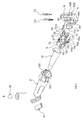
- the sensor unit 1 is an assembly that functions as an ultrasonic transmitting/receiving unit as a whole. As shown in FIG. 2, the sensor unit 1 includes an ultrasonic oscillator 11, an insulator 12, a first internal terminal 13a, a second internal terminal 13b, an elastic body 14, a case 15, and a lid 16. And a first external terminal 17a and a second external terminal 17b.
- the ultrasonic oscillator 11 is an element that transmits and receives ultrasonic waves.
- the ultrasonic oscillating element 11 is made of a material having a piezoelectric effect, such as PZT, and has a disk shape.
- the piezo effect is a characteristic in which a volume changes when a voltage is applied, and a voltage is generated when an external force is applied.
- Electrodes printed on substantially the entire surface are provided on both surfaces of the ultrasonic oscillator 11. When a voltage is applied from an external electric circuit between the electrodes on both sides via the lead wire 3 shown in FIG. Ultrasonic waves are generated by vibrating.
- the insulator 12 has a bottomed cylinder having a bottom portion 121 that covers a surface 111 (hereinafter, referred to as “front surface 111”) of the ultrasonic oscillator 11 that transmits and receives ultrasonic waves, and a side portion 122 that covers an outer peripheral surface. It is a member. Further, the insulator 12 projects from the inside of the side portion 122 at a position spaced apart from the bottom portion 121 by the plate thickness of the ultrasonic oscillation element 11, and is opposite to the front surface 111 of the ultrasonic oscillation element 11. Has a protruding piece 123 that covers a part of the surface 112 (hereinafter, referred to as “rear surface 112”).
- the insulator 12 is formed of an insulating material such as a resin material and a ceramic material.
- the first internal terminal 13a and the second internal terminal 13b are attached to the ultrasonic oscillator 11.
- the first internal terminal 13a is a terminal that electrically connects the ultrasonic oscillator 11 and the first external terminal 17a.
- the second internal terminal 13b is a terminal that electrically connects the ultrasonic oscillator 11 and the second external terminal 17b.
- the first internal terminal 13a and the second internal terminal 13b are formed of a metal plate.
- the first internal terminal 13a and the second internal terminal 13b are provided at positions facing each other with the elastic body 14 interposed therebetween.
- the one end of the first internal terminal 13a serves as a holding portion 131a that holds the front surface 111 and the back surface 112 of the ultrasonic oscillator 11 between them.
- the one end of the second internal terminal 13b also serves as a holding portion 131b that holds the front surface 111 and the back surface 112 of the ultrasonic oscillator 11 between them. Since the protruding piece 123 of the insulator 12 is interposed between the back surface 112 of the ultrasonic oscillator 11 and the sandwiching portion 131a, the sandwiching portion 131a does not directly contact the back surface 112 of the ultrasonic oscillator 11.
- the sandwiching portion 131b directly contacts the front surface 111 of the ultrasonic oscillator 11. Do not touch. That is, the first internal terminal 13 a is in contact with the front surface 111 of the ultrasonic oscillator 11, and the second internal terminal 13 b is in contact with the back surface 112 of the ultrasonic oscillator 11.
- first internal terminal 13a and the second internal terminal 13b have the same configuration, only the configuration of the first internal terminal 13a will be described below.
- the first internal terminal 13a has a rod portion 132a and a curved portion 133a in addition to the sandwiching portion 131a described above.
- the rod portion 132a is a linear portion extending in a direction along the central axis A from the ultrasonic oscillator 11 toward the lid 16.
- the curved portion 133a is a portion that is provided between the sandwiching portion 131a and the rod portion 132a and is curved in a wave shape with respect to the direction along the central axis A.
- the curved portion 133a has a structure that absorbs an external force applied to the first internal terminal 13a when the first internal terminal 13a is attached to the ultrasonic oscillator 11.
- the elastic body 14 is a substantially cylindrical member arranged coaxially with the central axis A of the ultrasonic oscillator 11. Of the two end faces on both sides in the axial direction, the first face abuts on the ultrasonic oscillator 11 and the second face abuts on the lid 16.
- the elastic body 14 is formed of an elastic material such as soft resin and rubber.
- the case 15 is a bottomed cylindrical case having an accommodating chamber 151 that accommodates the ultrasonic oscillator 11, the insulator 12, the first internal terminal 13a, the second internal terminal 13b, and the elastic body 14.
- the case 15 is made of an insulating resin material.
- the case 15 has a plurality of first locking claws 152 and a plurality of second locking claws 153.
- the first locking claw 152 is a claw for locking the case 15 with the lid 16.
- the second locking claw 153 is a claw for locking the case 15 with the housing part 2, specifically, with the body 21 described later.
- the lid 16 is a member that closes the accommodation chamber 151 of the case 15.
- the lid 16 is made of a conductive resin material.
- the lid 16 has a plurality of locking holes 161, a first communication portion 162a, a second communication portion 162b, a first fixing portion 163a, and a second fixing portion 163b.
- the locking hole 161 is a hole that engages with the first locking claw 152 of the case 15.
- the elastic body 14 is designed to have a larger dimension in the direction of the central axis A so that the elastic body 14 is compressed by the lid 16 and is accommodated in the accommodation chamber 151 in an elastically deformed state when the lid 16 is locked to the case 15. Has been done.
- the first communication portion 162a and the second communication portion 162b are portions that communicate the inside and outside of the accommodation chamber 151, and are holes in the present embodiment.
- the rod portion 132a of the first internal terminal 13a is inserted into the first communication portion 162a, and the tip portion of the rod portion 132a projects to the outside of the accommodation chamber 151.
- the second internal terminal 13b is inserted through the second communication portion 162b.
- the first fixing portion 163a is a portion to which the first external terminal 17a is fixed.
- the second fixing portion 163b is a portion to which the second external terminal 17b is fixed.
- the first external terminal 17a is a terminal that electrically connects the first internal terminal 13a and the lead wire 3 shown in FIG.
- the second external terminal 17b is a terminal that electrically connects the second internal terminal 13b and the lead wire 3.
- the first external terminal 17a and the second external terminal 17b are formed of a metal plate.
- the first external terminal 17a is fixed to the first fixing portion 163a, and is connected to the tip end portion of the rod portion 132a of the first internal terminal 13a protruding to the outside of the accommodation chamber 151.
- the second external terminal 17b is fixed to the second fixing portion 163b and, like the first external terminal 17a, is connected to the second internal terminal 13b.
- the first external terminal 17a is grounded.
- the conductor having the ground potential may be, for example, the ground potential portion provided in the electric circuit described above, or may be, for example, a metal part such as a body part that constitutes a vehicle.
- the housing part 2 is an assembly that functions as an ultrasonic wave propagation path as a whole. As shown in FIG. 1, the housing part 2 includes a body 21, a first metal tube 22, a second metal tube 23, and a reflector 24.
- the body 21 is a member made of a conductive resin material that holds and fixes the sensor unit 1, the first metal tube 22, the second metal tube 23, and the reflection plate 24.
- the first metal tube 22, the second metal tube 23, and the reflector 24 are attached to the body 21.
- the body 21 is fixed to the bottom surface of the tank 200.
- the sensor unit 1 is attached to the body 21 so that the central axis A of the ultrasonic oscillator 11 is coaxial with the central axis A of the first metal tube 22.
- the body 21 has a plurality of locking holes 222.
- the locking hole 222 is a hole that engages with the second locking claw 153 of the case 15.
- the sensor unit 1 is attached to the body 21 by locking the case 15 to the body 21.
- the lid 16 contacts the body 21 when the case 15 is locked to the body 21.
- the first metal tube 22 is a metal tube having a substantially truncated cone shape.
- the cross section of the first metal tube 22 in a plane orthogonal to the central axis A is circular.
- the first metal tube 22 is a propagation path of ultrasonic waves and forms the first propagation path 4 extending from the bottom surface of the case 15.
- the first propagation path 4 extends from the bottom surface of the case 15 along the central axis A toward the side opposite to the lid 16.
- the first propagation path 4 has a conical portion 41, a linear portion 42, and a step portion 43.
- the conical portion 41 is a truncated cone-shaped portion whose cross-sectional area gradually decreases with distance from the ultrasonic oscillator 11.
- the diameter of the cross section of the conical portion 41 in the plane orthogonal to the central axis A decreases as the distance from the ultrasonic oscillation element 11 increases.
- the straight portion 42 has a constant cross-sectional area, that is, a straight tubular portion.
- the step portion 43 is a portion that connects the conical portion 41 and the linear portion 42, and the cross-sectional area is reduced stepwise at the end portion of the conical portion 41 opposite to the end portion where the ultrasonic oscillator 11 is provided. It is a part. Due to the presence of the step portion 43, an annular reference surface 221 is formed in the first metal tube 22.
- the second metal tube 23 is a straight metal tube.
- the center axis B of the second metal tube 23 is orthogonal to the center axis A, and the second metal tube 23 is continuous with the end of the first metal tube 22 on the side of the straight portion 42 via the body 21. Is provided.
- the second metal tube 23 has a circular cross section in a plane orthogonal to the central axis B.
- the upper end portion of the second metal pipe 23 is located so as to project upward by a predetermined length from the liquid level when the amount of fuel stored in the tank 200 is maximum.
- the second metal tube 23 forms the second propagation path 5 which is a part of the propagation path of ultrasonic waves.
- the second propagation path 5 extends from the bottom of the tank 200 toward the liquid surface. Specifically, the second propagation path 5 extends vertically from the bottom of the tank 200.
- the diameter of the second propagation path 5 in this embodiment is equal to the diameter of the straight portion 42.
- the reflector 24 is a metal plate. When the reflector 24 is held and fixed to the body 21, the central axis A of the first metal tube 22 and the central axis B of the second metal tube 23 intersect at the reflecting surface 241 of the reflector 24. It is arranged to.
- the reflection plate 24 reflects the ultrasonic waves transmitted from the ultrasonic oscillator 11 toward the liquid surface of the fuel. Specifically, the reflector 24 directs the ultrasonic waves traveling along the central axis A of the first metal tube 22 in the direction in which the incident angle to the liquid surface is 0°, that is, in the direction orthogonal to the liquid surface. It is installed so that it reflects. In this embodiment, the reflection plate 24 is provided so as to be inclined at 45° with respect to the liquid surface.
- the ultrasonic oscillator 11 when a pulsed voltage is applied to the ultrasonic oscillator 11 via the first internal terminal 13a and the second internal terminal 13b, the ultrasonic oscillator 11 vibrates and the case 15 Ultrasonic waves are transmitted to the first propagation path 4 via the bottom surface.
- the sensor unit 1 receives the reflected wave reflected by the liquid surface or the reflected wave reflected by the reference surface 221 via the reflection plate 24, the bottom surface of the case 15 vibrates due to the pressure action, and the ultrasonic oscillator element 11 also accordingly. Vibrate.
- the ultrasonic oscillation element 11 generates a voltage, and the voltage is input as an output signal to the external electric circuit via the first internal terminal 13a and the second internal terminal 13b.
- the grounded first external terminal 17a is fixed to the conductive resin lid 16, and the lid 16 is in contact with the conductive resin body 21. Further, the body 21 holds and fixes the first metal tube 22. In this way, the first external terminal 17a and the first metal pipe 22 are electrically connected via the lid 16 and the body 21, and the first metal pipe 22 is grounded.
- the first external terminal 17a which is grounded, and the first metal tube 22 are electrically connected to each other through the conductive resin lid 16 and the conductive resin body 21. ing.
- the static electricity that is generated as the liquid in the tank 200 rocks and charges the first metal tube 22 can be always released to the grounded first external terminal 17a. It is possible to prevent the tube 22 from being charged. Therefore, it is possible to prevent erroneous detection of the liquid surface position due to the charging of the first metal tube 22.
- the body 21 is directly attached to the bottom of the tank 200, so that the body 21 further collects static electricity generated in the tank 200 itself due to the swing of the liquid in the tank 200. Will end up.
- the liquid surface detection apparatus 100 of the present embodiment is in an environment in which the first metal tube 22 is more likely to be in a charged state as compared with the configuration in which the body is not directly attached to the bottom of the tank. Even in such an environment, it is possible to prevent the first metal tube 22 from being charged.
- the first internal terminal 13a and the second internal terminal 13b correspond to two internal terminals
- the first external terminal 17a and the second external terminal 17b correspond to two external terminals
- the first metal The pipe 22 corresponds to a metal pipe.
- the shape of the first internal terminal 13c is different from that of the first internal terminal 13a of the first embodiment.
- the lid 16 of the second embodiment is different from the lid 16 of the first embodiment in that it is made of an insulating resin material.
- the same reference numerals are used for the configurations common to the first embodiment, and the description thereof will be omitted.
- the configuration different from the form will be mainly described.
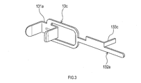
- the first internal terminal 13c of the second embodiment differs from the first internal terminal 13a of the first embodiment in that it does not have the curved portion 133a and that it has the bent portion 133c.
- the bending portion 133c is a portion that extends perpendicularly to the rod portion 132a.
- the bending portion 133c projects outside the case 15 from between the case 15 and the lid 16.
- the case 15 may have a groove formed on the surface that comes into contact with the lid 16 and through which the bending portion 133c can be inserted.
- the grounded first external terminal 17a is connected to the rod portion 132a of the first internal terminal 13c, and the bending portion 133c of the first internal terminal 13c is made of a conductive resin. It is in contact with the body 21. Further, the body 21 holds and fixes the first metal tube 22. In this way, the first external terminal 17a and the first metal tube 22 are electrically connected via the first internal terminal 13c and the body 21, and the first metal tube 22 is grounded. There is.
- the grounded first external terminal 17a and the first metal tube 22 are electrically connected via the metal first internal terminal 13c and the conductive resin body 21. It is connected. This can prevent the first metal tube 22 from being charged. In particular, in the configuration of this embodiment, it is not necessary to form the lid 16 with a conductive resin material.
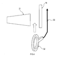
- the third embodiment differs from the first embodiment in that a grounding member 32 is provided and that the first external terminal 17a is not grounded.
- the lid 16 of the third embodiment is different from the lid 16 of the first embodiment in that it is made of an insulating resin material.
- the same reference numerals are used for the configurations common to the first embodiment, and the description thereof will be omitted. The configuration different from the form will be mainly described.
- the ground member 32 is grounded via the lead wire 33.
- the ground member 32 is a ring-shaped member formed of a conductive material such as a metal and a conductive resin material.
- the grounding member 32 is sandwiched between the body 21 and the lid 16 in a state where the case 15 is inserted through the central opening, and comes into pressure contact with the body.
- the ground member 32 is not limited to a flat shape and may be, for example, a metal plate having a wavy undulation. In the case of a metal plate having such a shape, the pressing force can be increased by the spring force caused by the undulations being crushed.
- the grounding member 32 which is grounded, is in contact with the body 21 made of conductive resin. Further, the body 21 holds and fixes the first metal tube 22. In this way, the grounding member 32 and the first metal pipe 22 are electrically connected via the body 21, and the first metal pipe 22 is grounded.
- the grounding member 32 which is grounded, and the first metal pipe 22 are electrically connected via the body 21 made of a conductive resin. This can prevent the first metal tube 22 from being charged.
- the case 15 is made of an insulating resin material, but the case 15 may be made of a conductive resin material, for example.
- This can increase the number of conductive paths between the first metal tube 22 and the first external terminal 17a.
- the conductive path through the body 21 and the lid 16 grounds the static electricity that charges the first metal tube 22. It can be released to the terminal 17a. Therefore, it is possible to further prevent the first metal tube 22 from being charged.
- the first internal terminal 13c having no curved portion is illustrated, but the first internal terminal has the same curved shape as the first internal terminal 13a of the first embodiment. It may be configured to have a part.
- ground contact member 32 is an annular member
- shape of the ground contact member is not limited to the annular shape, and may be, for example, a U shape. ..
Landscapes
- Physics & Mathematics (AREA)
- Electromagnetism (AREA)
- Thermal Sciences (AREA)
- Fluid Mechanics (AREA)
- General Physics & Mathematics (AREA)
- Acoustics & Sound (AREA)
- Measurement Of Levels Of Liquids Or Fluent Solid Materials (AREA)
Abstract
液面の位置を検出する液面検出装置(100)は、センサ部(1)と、金属管(22)と、ボディ(21)と、を備える。センサ部は、超音波を送受信可能である。金属管は、センサ部から送信された超音波が伝播する伝播経路を形成する。ボディは、金属管及びセンサ部を保持する。金属管は、接地されている。
Description
本国際出願は、2018年11月28日に日本国特許庁に出願された日本国特許出願第2018-222494号に基づく優先権を主張するものであり、日本国特許出願第2018-222494号の全内容を本国際出願に参照により援用する。
本開示は、液面検出装置に関する。
特許文献1には、液体を貯蔵するタンク内の底部に設けられ、超音波発振素子によって超音波を送信し、液面で反射した反射波を受信することにより、液面の位置を検出するように構成された液面検出装置が開示されている。超音波発振素子は、当該超音波発振素子と電気的に接続する内部端子とともに、ケースに収容されている。ケースから送信された超音波を伝播する伝播経路は、伝播効率を高めるため、金属管により形成されている。ケース及び金属管は、樹脂製のボディによって保持されている。
発明者の詳細な検討の結果、上述した液面検出装置では、タンク内の液体の揺動に伴い、樹脂製のボディに静電気が発生し、金属管が帯電状態となるという課題が見出された。帯電状態の金属管が内部端子へ放電すると、液面位置の誤検出が生じ得る。
本開示の一局面は、金属管が帯電状態となることを抑制することができる液面検出装置を提供する。
本開示の一態様は、液面の位置を検出する液面検出装置であって、センサ部と、金属管と、ボディと、を備える。センサ部は、超音波を送受信可能である。金属管は、センサ部から送信された超音波が伝播する伝播経路を形成する。ボディは、金属管及びセンサ部を保持する。金属管は、接地されている。
このような構成によれば、金属管が接地されているため、金属管が帯電状態となることを抑制することができる。したがって、金属管が帯電状態となることに起因する、液面位置の誤検出を生じにくくすることができる。
以下、本開示の例示的な実施形態について図面を参照しながら説明する。
[1.第1実施形態]
[1-1.構成]
図1に示す液面検出装置100は、車両に搭載され、液体の燃料を貯蔵するタンク200内の底部において、超音波を送信し、液面で反射した反射波を受信することにより、液面の位置を検出する装置である。なお、図1に示す液面検出装置100の一部については、内部構造を分かりやすく示すため、断面ではなく側面を示している。液面検出装置100は、機能的な見地から見て、大きく2つの機能部、具体的には、センサ部1と、ハウジング部2と、を備える。
[1-1.構成]
図1に示す液面検出装置100は、車両に搭載され、液体の燃料を貯蔵するタンク200内の底部において、超音波を送信し、液面で反射した反射波を受信することにより、液面の位置を検出する装置である。なお、図1に示す液面検出装置100の一部については、内部構造を分かりやすく示すため、断面ではなく側面を示している。液面検出装置100は、機能的な見地から見て、大きく2つの機能部、具体的には、センサ部1と、ハウジング部2と、を備える。
センサ部1は、全体として超音波の送受信部として機能するアセンブリである。図2に示すように、センサ部1は、超音波発振素子11と、インシュレータ12と、第1の内部端子13aと、第2の内部端子13bと、弾性体14と、ケース15と、蓋16と、第1の外部端子17aと、第2の外部端子17bと、を備える。
超音波発振素子11は、超音波を送受信する素子である。超音波発振素子11は、PZTなどのピエゾ効果を有する物質によって、円盤状に構成されている。ピエゾ効果とは、電圧が印加されると体積が変化する一方、外部から力を受けると電圧を発生する特性のことである。超音波発振素子11の両面にはそれぞれ、ほぼ全面に印刷された電極が設けられている。超音波発振素子11は、両面の電極間に、図1に示すリード線3を介して外部の電気回路から電圧が印加されると、上述したピエゾ効果により板厚方向である中心軸A方向に振動することにより超音波を発振する。
インシュレータ12は、超音波発振素子11における超音波を送受信する面111(以下、「おもて面111」と称す)を覆う底部121と、外周面を覆う側部122と、を有する有底円筒状の部材である。また、インシュレータ12は、底部121に対して超音波発振素子11の板厚分だけ間隔を空けた位置に、側部122の内側から突出し、超音波発振素子11におけるおもて面111とは反対の面112(以下、「裏面112」と称す)の一部を覆う突出片123を有する。インシュレータ12は、例えば樹脂材料及びセラミックス材料などの絶縁材料で形成されている。
第1の内部端子13a及び第2の内部端子13bは、超音波発振素子11に取り付けられている。第1の内部端子13aは、超音波発振素子11と第1の外部端子17aとを電気的に接続する端子である。第2の内部端子13bは、超音波発振素子11と第2の外部端子17bとを電気的に接続する端子である。第1の内部端子13a及び第2の内部端子13bは、金属板で形成されている。第1の内部端子13aと第2の内部端子13bとは、弾性体14を挟んで対向する位置に設けられている。
第1の内部端子13aは、その一端が、超音波発振素子11のおもて面111と裏面112とを挟んで保持する、挟持部131aとなっている。第2の内部端子13bも同様、その一端が、超音波発振素子11のおもて面111と裏面112とを挟んで保持する、挟持部131bとなっている。超音波発振素子11の裏面112と挟持部131aとの間にはインシュレータ12の突出片123が介在するため、挟持部131aは超音波発振素子11の裏面112とは直接接触しない。一方、超音波発振素子11のおもて面111と挟持部131bとの間にはインシュレータ12の底部121が介在するため、挟持部131bは超音波発振素子11のおもて面111とは直接接触しない。つまり、第1の内部端子13aは超音波発振素子11のおもて面111と接触し、第2の内部端子13bは超音波発振素子11の裏面112と接触している。
第1の内部端子13aと第2の内部端子13bとは、同様の構成を有するため、以下では、第1の内部端子13aの構成についてのみ説明する。
第1の内部端子13aは、上述した挟持部131aに加え、棒部132a及び湾曲部133aを有する。棒部132aは、超音波発振素子11から蓋16に向かって中心軸Aに沿う方向に延びる直線状の部分である。湾曲部133aは、挟持部131aと棒部132aとの間に設けられた、中心軸Aに沿う方向に対して波状に湾曲した部分である。湾曲部133aは、第1の内部端子13aが超音波発振素子11に取り付けられる際に、第1の内部端子13aに加わる外力を吸収する構造になっている。
弾性体14は、超音波発振素子11の中心軸Aと同軸に配置された概略円柱状の部材である。軸方向両側の2つの端面のうち、第1の面が超音波発振素子11に当接し、第2の面が蓋16に当接する。弾性体14は、例えば柔軟な樹脂及びゴムなどの弾性材料で形成されている。
ケース15は、超音波発振素子11、インシュレータ12、第1の内部端子13a、第2の内部端子13b及び弾性体14を収容する収容室151を有する有底円筒状のケースである。ケース15は、絶縁樹脂材料で形成されている。ケース15は、複数の第1の係止爪152及び複数の第2の係止爪153を有する。第1の係止爪152は、ケース15を蓋16と係止するための爪である。第2の係止爪153は、ケース15をハウジング部2、具体的には後述するボディ21と係止するための爪である。
蓋16は、ケース15の収容室151を閉じる部材である。蓋16は、導電樹脂材料で形成されている。蓋16は、複数の係止孔161、第1の連通部162a、第2の連通部162b、第1の固定部163a及び第2の固定部163bを有する。係止孔161は、ケース15の第1の係止爪152と係合する孔である。蓋16がケース15に係止された状態において、弾性体14は、蓋16により圧縮され、弾性変形した状態で収容室151に収容されるように、中心軸Aの方向における寸法が大きめに設計されている。このため、超音波発振素子11は、弾性体14の弾性力によりケース15の底面に押し付けられた状態で固定される。第1の連通部162a及び第2の連通部162bは、収容室151の内外を連通する部分であり、本実施形態では、孔である。第1の連通部162aには第1の内部端子13aの棒部132aが挿通され、棒部132aの先端部は収容室151の外側へ突出する。第2の連通部162bには第2の内部端子13bが同様に挿通される。第1の固定部163aは、第1の外部端子17aが固定される部分である。第2の固定部163bは、第2の外部端子17bが固定される部分である。
第1の外部端子17aは、第1の内部端子13aと図1に示すリード線3とを電気的に接続する端子である。第2の外部端子17bは、第2の内部端子13bとリード線3とを電気的に接続する端子である。第1の外部端子17a及び第2の外部端子17bは、金属板で形成されている。本実施形態では、第1の外部端子17aは、第1の固定部163aに固定され、収容室151の外側へ突出する第1の内部端子13aの棒部132aの先端部と接続する。第2の外部端子17bは、第2の固定部163bに固定され、第1の外部端子17aと同様、第2の内部端子13bと接続する。なお、第1の外部端子17aは接地されている。接地されているとは、接地電位となっている導体と電気的につながっていることを意味する。接地電位となっている導体は、例えば、上述した電気回路に設けられた接地電位部であってもよく、また例えば、車両を構成するボディ部品などの金属部品であってもよい。
次に、ハウジング部2について説明する。ハウジング部2は、全体として超音波の伝播経路として機能するアセンブリである。図1に示すように、ハウジング部2は、ボディ21と、第1の金属管22と、第2の金属管23と、反射板24と、を有する。
ボディ21は、センサ部1、第1の金属管22、第2の金属管23及び反射板24を保持及び固定する導電樹脂材料で形成された部材である。第1の金属管22、第2の金属管23及び反射板24は、ボディ21に装着されている。ボディ21は、タンク200の底面に固定されている。センサ部1は、超音波発振素子11の中心軸Aが第1の金属管22の中心軸Aと同軸となるようにボディ21に取り付けられている。具体的には、図2に示すように、ボディ21は、複数の係止孔222を有する。係止孔222は、ケース15の第2の係止爪153と係合する孔である。ケース15がボディ21に係止されることにより、センサ部1はボディ21に取り付けられている。なお、図1に示すように、ケース15がボディ21に係止された状態において、蓋16がボディ21に接触する。
第1の金属管22は、概略円錐台状の金属製の筒である。第1の金属管22の中心軸Aと直交する面における断面は円形である。第1の金属管22は、超音波の伝播経路であって、ケース15の底面から延びる第1の伝播経路4を形成する。第1の伝播経路4は、ケース15の底面から、中心軸Aに沿って、蓋16と反対側に向かって延びている。第1の伝播経路4は、円錐部41と、直線部42と、段部43と、を有する。円錐部41は、超音波発振素子11から離れるにつれて断面積が徐々に縮小する円錐台状の部分である。換言すると、円錐部41は中心軸Aと直交する面における断面の直径が、超音波発振素子11から離れるにつれて縮小する。直線部42は、断面積が一定、つまり直管状の部分である。段部43は、円錐部41と直線部42とを連結する部分であって、円錐部41における超音波発振素子11が設けられる端部と反対側の端部においてステップ状に断面積が縮小する部分である。段部43の存在により、第1の金属管22には、円環状の基準面221が形成されている。
第2の金属管23は、直管状の金属製の筒である。第2の金属管23は、第2の金属管23の中心軸Bが中心軸Aと直交し、かつ第1の金属管22における直線部42側の端部と、ボディ21を介して連続するように設けられている。第2の金属管23は、中心軸Bと直交する面における断面が円形である。第2の金属管23の上方端部は、タンク200の燃料の貯蔵量が最大時における液面よりも、所定長さだけ上方に突出するように位置する。第2の金属管23は、超音波の伝播経路の一部である第2の伝播経路5を形成している。第2の伝播経路5は、タンク200の底部から液面に向かって延びている。具体的には、第2の伝播経路5は、タンク200の底部から鉛直方向に延びている。本実施形態における第2の伝播経路5の直径は、直線部42の直径と等しい。
反射板24は、金属製の板である。反射板24は、ボディ21に保持及び固定された状態において、第1の金属管22の中心軸Aと第2の金属管23の中心軸Bとが、反射板24の反射面241にて交差するように配置されている。反射板24は、超音波発振素子11から送信された超音波を燃料の液面に向けて反射する。具体的には、反射板24は、第1の金属管22の中心軸Aに沿って進む超音波を、液面への入射角が0°となる方向、すなわち液面に直交する方向に向けて反射するように設置されている。本実施形態では、反射板24は、液面に対して45°傾斜するように設けられている。
以上のような構成により、第1の内部端子13a及び第2の内部端子13bを介して超音波発振素子11にパルス状電圧が印加されると、超音波発振素子11が振動し、ケース15の底面を介して超音波が第1の伝播経路4に送信される。反射板24を介し液面で反射した反射波又は基準面221で反射した反射波をセンサ部1が受信すると、その圧力作用によりケース15の底面が振動し、これに伴い超音波発振素子11も振動する。これにより、超音波発振素子11は電圧を発生し、当該電圧が第1の内部端子13a及び第2の内部端子13bを介して外部の電気回路に出力信号として入力される。
本実施形態では、接地されている第1の外部端子17aが導電樹脂製の蓋16に固定され、当該蓋16が導電樹脂製のボディ21に接触している。また、ボディ21は、第1の金属管22を保持及び固定している。このように、第1の外部端子17aと第1の金属管22とが、蓋16及びボディ21を介して電気的に接続されており、第1の金属管22が接地されている。
[1-2.効果]
以上詳述した第1実施形態によれば、以下の効果が得られる。
以上詳述した第1実施形態によれば、以下の効果が得られる。
(1a)本実施形態では、接地されている第1の外部端子17aと、第1の金属管22と、が導電樹脂製の蓋16及び導電樹脂製のボディ21を介して電気的に接続されている。これにより、タンク200内の液体の揺動に伴い発生し、第1の金属管22に帯電する静電気を、接地されている第1の外部端子17aに常に逃がすことができるので、第1の金属管22が帯電状態となることを抑制することができる。したがって、第1の金属管22が帯電状態となることに起因する、液面位置の誤検出を生じにくくすることができる。
特に、本実施形態の液面検出装置100では、ボディ21が直接タンク200の底部に取り付けられるため、タンク200内の液体の揺動に伴い当該タンク200自体に発生する静電気を更にボディ21が拾ってしまう。このように、本実施形態の液面検出装置100は、ボディが直接タンクの底部に取り付けられない構成と比較して、第1の金属管22がより帯電状態となりやすい環境である。このような環境においても、第1の金属管22が帯電状態となることを抑制することができる。
なお、第1の内部端子13a及び第2の内部端子13bが2つの内部端子に相当し、第1の外部端子17a及び第2の外部端子17bが2つの外部端子に相当し、第1の金属管22が金属管に相当する。
[2.第2実施形態]
[2-1.構成]
図3に示すように、第2実施形態では、第1の内部端子13cの形状が第1実施形態の第1の内部端子13aと異なる。また、第2実施形態の蓋16は、絶縁樹脂材料で形成されている点が、第1実施形態の蓋16と異なる。その他、第2実施形態の液面検出装置の基本的な構成は第1実施形態と同様であるため、第1実施形態と共通する構成については同一符号を用いて説明を省略し、第1実施形態と相違する構成を中心に説明する。
[2-1.構成]
図3に示すように、第2実施形態では、第1の内部端子13cの形状が第1実施形態の第1の内部端子13aと異なる。また、第2実施形態の蓋16は、絶縁樹脂材料で形成されている点が、第1実施形態の蓋16と異なる。その他、第2実施形態の液面検出装置の基本的な構成は第1実施形態と同様であるため、第1実施形態と共通する構成については同一符号を用いて説明を省略し、第1実施形態と相違する構成を中心に説明する。
図3に示すように、第2実施形態の第1の内部端子13cは、湾曲部133aを有しない点及び屈折部133cを有する点が、第1実施形態の第1の内部端子13aと異なる。屈折部133cは、棒部132aに対して垂直に延びる部分である。屈折部133cは、ケース15と蓋16との間からケース15の外へ突出する。ケース15がボディ21に係止した状態において、屈折部133cは、ボディ21と蓋16との間に挟まれ、ボディ21に圧接する。なお、ケース15には、蓋16と接触する側の面に、屈折部133cを挿通可能な溝が形成されていてもよい。
以上のように、本実施形態では、接地されている第1の外部端子17aが第1の内部端子13cの棒部132aに接続され、第1の内部端子13cの屈折部133cが導電樹脂製のボディ21に接触している。また、ボディ21は、第1の金属管22を保持及び固定している。このように、第1の外部端子17aと第1の金属管22とが、第1の内部端子13c及びボディ21を介して電気的に接続されており、第1の金属管22が接地されている。
[2-2.効果]
(2a)本実施形態では、接地されている第1の外部端子17aと第1の金属管22とが、金属製の第1の内部端子13c及び導電樹脂製のボディ21を介して電気的に接続されている。これにより、第1の金属管22が帯電状態となることを抑制することができる。特に、本実施形態の構成では、蓋16を導電樹脂材料で形成する必要がない。
(2a)本実施形態では、接地されている第1の外部端子17aと第1の金属管22とが、金属製の第1の内部端子13c及び導電樹脂製のボディ21を介して電気的に接続されている。これにより、第1の金属管22が帯電状態となることを抑制することができる。特に、本実施形態の構成では、蓋16を導電樹脂材料で形成する必要がない。
[3.第3実施形態]
図4に示すように、第3実施形態では、接地部材32を備える点、及び、第1の外部端子17aが接地されていない点が、第1実施形態と異なる。また、第3実施形態の蓋16は、絶縁樹脂材料で形成されている点が、第1実施形態の蓋16と異なる。その他、第3実施形態の液面検出装置の基本的な構成は第1実施形態と同様であるため、第1実施形態と共通する構成については同一符号を用いて説明を省略し、第1実施形態と相違する構成を中心に説明する。
図4に示すように、第3実施形態では、接地部材32を備える点、及び、第1の外部端子17aが接地されていない点が、第1実施形態と異なる。また、第3実施形態の蓋16は、絶縁樹脂材料で形成されている点が、第1実施形態の蓋16と異なる。その他、第3実施形態の液面検出装置の基本的な構成は第1実施形態と同様であるため、第1実施形態と共通する構成については同一符号を用いて説明を省略し、第1実施形態と相違する構成を中心に説明する。
[3-1.構成]
接地部材32は、リード線33を介して接地されている。接地部材32は、例えば金属及び導電樹脂材料などの導電材料で形成されている円環状の部材である。接地部材32は、中央の開口にケース15が挿通された状態で、ボディ21と蓋16との間に挟まれ、ボディに圧接する。なお、接地部材32は、平らな形状に限らず、例えば、波状の起伏を有する形状の金属板であってもよい。このような形状の金属板の場合、起伏が潰されることによるバネ力により、圧接力を高めることができる。
接地部材32は、リード線33を介して接地されている。接地部材32は、例えば金属及び導電樹脂材料などの導電材料で形成されている円環状の部材である。接地部材32は、中央の開口にケース15が挿通された状態で、ボディ21と蓋16との間に挟まれ、ボディに圧接する。なお、接地部材32は、平らな形状に限らず、例えば、波状の起伏を有する形状の金属板であってもよい。このような形状の金属板の場合、起伏が潰されることによるバネ力により、圧接力を高めることができる。
以上のように、本実施形態では、接地されている接地部材32が導電樹脂製のボディ21に接触している。また、ボディ21は、第1の金属管22を保持及び固定している。このように、接地部材32と第1の金属管22とが、ボディ21を介して電気的に接続されており、第1の金属管22が接地されている。
[3-2.効果]
(3a)本実施形態では、接地されている接地部材32と第1の金属管22とが、導電樹脂製のボディ21を介して電気的に接続されている。これにより、第1の金属管22が帯電状態となることを抑制することができる。特に、本実施形態の構成では、第1の外部端子17aを接地させる必要がなく、蓋16も導電樹脂材料で形成する必要がない。
(3a)本実施形態では、接地されている接地部材32と第1の金属管22とが、導電樹脂製のボディ21を介して電気的に接続されている。これにより、第1の金属管22が帯電状態となることを抑制することができる。特に、本実施形態の構成では、第1の外部端子17aを接地させる必要がなく、蓋16も導電樹脂材料で形成する必要がない。
[4.他の実施形態]
以上、本開示の実施形態について説明したが、本開示は、上記各実施形態に限定されることなく、種々の形態を採り得ることは言うまでもない。
以上、本開示の実施形態について説明したが、本開示は、上記各実施形態に限定されることなく、種々の形態を採り得ることは言うまでもない。
(4a)上記第1実施形態では、ケース15が絶縁樹脂材料で形成されていたが、例えば、ケース15が導電樹脂材料で形成されていてもよい。これにより、第1の金属管22と第1の外部端子17aとの間の導電経路を増やすことができる。具体的には、ボディ21及び蓋16を介する導電経路に加え、ボディ21、ケース15及び蓋16を介する導電経路により、第1の金属管22に帯電する静電気を接地されている第1の外部端子17aに逃がすことができる。したがって、第1の金属管22が帯電状態となることをより一層抑制することができる。
(4b)上記第2実施形態では、湾曲部を有しない構成の第1の内部端子13cを例示したが、第1の内部端子は、第1実施形態の第1の内部端子13aと同様、湾曲部を有するように構成されてもよい。
(4c)上記第3実施形態では、接地部材32が円環状の部材である構成を例示したが、接地部材の形状は円環状に限定されるものではなく、例えばU字状であってもよい。
(4d)上記各実施形態における1つの構成要素が有する機能を複数の構成要素として分散させたり、複数の構成要素が有する機能を1つの構成要素に統合したりしてもよい。また、上記各実施形態の構成の一部を省略してもよい。また、上記実施形態の構成の少なくとも一部を、他の上記実施形態の構成に対して付加、置換等してもよい。
Claims (6)
- 液面の位置を検出する液面検出装置(100)であって、
超音波を送受信可能なセンサ部(1)と、
前記センサ部から送信された超音波が伝播する伝播経路を形成する金属管(22)と、
前記金属管及び前記センサ部を保持するボディ(21)と、
を備え、
前記金属管は、接地されている、液面検出装置。 - 請求項1に記載の液面検出装置であって、
前記センサ部は、
超音波を送受信可能な超音波発振素子(11)と、
前記超音波発振素子を収容する収容室(151)を有するケース(15)と、
前記ボディに接触するように設けられ、前記収容室を閉じる蓋(16)と、
前記収容室の外側において前記蓋に固定された2つの外部端子(17a,17b)と、
前記超音波発振素子と前記2つの外部端子のそれぞれとを電気的に接続する2つの内部端子(13a,13b)と、
を備える、液面検出装置。 - 請求項2に記載の液面検出装置であって、
前記2つの外部端子の一方(17a)は、接地されており、
前記ボディ及び前記蓋はそれぞれ、導電樹脂で形成されている、液面検出装置。 - 請求項3に記載の液面検出装置であって、
前記ケースは、導電樹脂で形成されており、前記ボディと接触するように設けられる、液面検出装置。 - 請求項2に記載の液面検出装置であって、
前記2つの外部端子の一方(17a)は、接地されており、
前記ボディは、導電樹脂で形成されており、
前記2つの内部端子の一方(13a)は、前記2つの外部端子のうち接地された方と前記ボディとを電気的に接続する、液面検出装置。 - 請求項2に記載の液面検出装置であって、
接地された接地部材(32)を更に備え、
前記ボディは、導電樹脂で形成されており、
前記接地部材は、前記ボディに接触するように設けられる、液面検出装置。
Applications Claiming Priority (2)
| Application Number | Priority Date | Filing Date | Title |
|---|---|---|---|
| JP2018222494A JP6927183B2 (ja) | 2018-11-28 | 2018-11-28 | 液面検出装置 |
| JP2018-222494 | 2018-11-28 |
Publications (1)
| Publication Number | Publication Date |
|---|---|
| WO2020111005A1 true WO2020111005A1 (ja) | 2020-06-04 |
Family
ID=70853728
Family Applications (1)
| Application Number | Title | Priority Date | Filing Date |
|---|---|---|---|
| PCT/JP2019/045995 Ceased WO2020111005A1 (ja) | 2018-11-28 | 2019-11-25 | 液面検出装置 |
Country Status (2)
| Country | Link |
|---|---|
| JP (1) | JP6927183B2 (ja) |
| WO (1) | WO2020111005A1 (ja) |
Families Citing this family (1)
| Publication number | Priority date | Publication date | Assignee | Title |
|---|---|---|---|---|
| KR102705116B1 (ko) * | 2023-12-08 | 2024-09-11 | 주식회사 미래와도전 | 고온 및 고방사선의 비가시성 매질 내부 시각화를 위한 초음파센서 보호튜브장치 |
Citations (2)
| Publication number | Priority date | Publication date | Assignee | Title |
|---|---|---|---|---|
| WO2018211823A1 (ja) * | 2017-05-16 | 2018-11-22 | 株式会社デンソー | 液面検出装置 |
| WO2018211822A1 (ja) * | 2017-05-16 | 2018-11-22 | 株式会社デンソー | 液面検出装置 |
-
2018
- 2018-11-28 JP JP2018222494A patent/JP6927183B2/ja active Active
-
2019
- 2019-11-25 WO PCT/JP2019/045995 patent/WO2020111005A1/ja not_active Ceased
Patent Citations (2)
| Publication number | Priority date | Publication date | Assignee | Title |
|---|---|---|---|---|
| WO2018211823A1 (ja) * | 2017-05-16 | 2018-11-22 | 株式会社デンソー | 液面検出装置 |
| WO2018211822A1 (ja) * | 2017-05-16 | 2018-11-22 | 株式会社デンソー | 液面検出装置 |
Also Published As
| Publication number | Publication date |
|---|---|
| JP2020085727A (ja) | 2020-06-04 |
| JP6927183B2 (ja) | 2021-08-25 |
Similar Documents
| Publication | Publication Date | Title |
|---|---|---|
| WO2020111132A1 (ja) | 液面検出装置 | |
| CN103562687B (zh) | 超声波发送接收器及超声波流量计 | |
| US9339846B2 (en) | Ultrasonic sensor assembly | |
| JP6443322B2 (ja) | 超音波センサ | |
| JP7196798B2 (ja) | 超音波センサ | |
| CN102726064A (zh) | 超声波振动装置 | |
| JP7192640B2 (ja) | 超音波センサ | |
| US11667247B2 (en) | Ultrasonic sensor | |
| CN115023957B (zh) | 超声波传感器 | |
| WO2020111005A1 (ja) | 液面検出装置 | |
| JP7167567B2 (ja) | 超音波センサ | |
| JP7088099B2 (ja) | 超音波センサ | |
| KR101218550B1 (ko) | 초음파 센서 | |
| US7628076B2 (en) | Ultrasound sensor | |
| WO2019142859A1 (ja) | 液面検出装置 | |
| JP2019132642A (ja) | 液面検出装置 | |
| WO2019172334A1 (ja) | 液面検出装置 | |
| JP6852716B2 (ja) | 液面検出装置 | |
| WO2019131664A1 (ja) | 液面検出装置及び液面検出装置の製造方法 | |
| JP4768684B2 (ja) | 超音波センサ | |
| JP2023116035A (ja) | 圧電トランスデューサ | |
| WO2019131663A1 (ja) | 液面検出装置 | |
| WO2019139083A1 (ja) | 液面検出装置 | |
| JP2017078622A (ja) | 圧力センサ、および、圧力センサの製造方法 | |
| JP2023030319A (ja) | 超音波トランスデューサ |
Legal Events
| Date | Code | Title | Description |
|---|---|---|---|
| 121 | Ep: the epo has been informed by wipo that ep was designated in this application |
Ref document number: 19889912 Country of ref document: EP Kind code of ref document: A1 |
|
| NENP | Non-entry into the national phase |
Ref country code: DE |
|
| 122 | Ep: pct application non-entry in european phase |
Ref document number: 19889912 Country of ref document: EP Kind code of ref document: A1 |