WO2020105697A1 - モーションキャプチャ・カメラシステム及びキャリブレーション方法 - Google Patents
モーションキャプチャ・カメラシステム及びキャリブレーション方法Info
- Publication number
- WO2020105697A1 WO2020105697A1 PCT/JP2019/045552 JP2019045552W WO2020105697A1 WO 2020105697 A1 WO2020105697 A1 WO 2020105697A1 JP 2019045552 W JP2019045552 W JP 2019045552W WO 2020105697 A1 WO2020105697 A1 WO 2020105697A1
- Authority
- WO
- WIPO (PCT)
- Prior art keywords
- camera
- coordinate system
- mounter
- motion capture
- global coordinate
- Prior art date
- Legal status (The legal status is an assumption and is not a legal conclusion. Google has not performed a legal analysis and makes no representation as to the accuracy of the status listed.)
- Ceased
Links
Images








Classifications
-
- G—PHYSICS
- G06—COMPUTING OR CALCULATING; COUNTING
- G06T—IMAGE DATA PROCESSING OR GENERATION, IN GENERAL
- G06T7/00—Image analysis
- G06T7/80—Analysis of captured images to determine intrinsic or extrinsic camera parameters, i.e. camera calibration
-
- H—ELECTRICITY
- H04—ELECTRIC COMMUNICATION TECHNIQUE
- H04N—PICTORIAL COMMUNICATION, e.g. TELEVISION
- H04N23/00—Cameras or camera modules comprising electronic image sensors; Control thereof
- H04N23/60—Control of cameras or camera modules
Definitions
- the present invention relates to a camera system for motion capture.
- Motion capture technology is widely used for various motion measurements. However, in team sports, it is not performed to capture the motion of each player during the game and analyze the motion. For example, moving images of sports such as soccer, rugby, baseball, volleyball, and handball are not acquired, and motion analysis of each player is not performed based on the acquired moving images.
- motion capture does not reduce the performance of the player
- motion capture is a supporting operation (TV broadcast, team Staff, spectators, etc.)
- large storage capacity TV broadcast, team Staff, spectators, etc.
- synchronization between high-speed cameras over a long distance synchronization between high-speed cameras over a long distance
- e ability to receive large amounts of data in real time
- f long time It is necessary to satisfy the conditions such as stable system with operable performance, and (g) camera calibration for accurate 3D reconstruction.
- Optical motion capture and motion capture using an inertial sensor are known as conventional typical motion capture techniques. These motion captures have the drawback that it takes time to prepare a measurement for attaching a reflective marker or an inertial sensor to a target body, and further, the marker or the sensor may hinder the smooth movement of the target. Cannot be used to acquire the action of each player during a match. Moreover, these motion captures have a limited measurement space. In optical motion capture using an infrared light source, it is necessary to perform measurement in a space surrounded by a camera that is not affected by external light, and when receiving sensor data wirelessly, wireless signals are limited. It was necessary to measure in space.
- Non-Patent Document 1 performs motion capture from the images of a plurality of RGB cameras in a completely unconstrained manner. From the indoor living space to the wide outdoor sports field principle Specifically, this is a technology that enables motion measurement if images can be acquired.
- the camera parameters include optical parameters such as lens distortion, internal parameters such as focal length and optical center, and external parameters representing the position / orientation of the camera in the space where the camera is installed.
- Conventional camera calibration is performed by calibrating all of these parameters by photographing a calibration instrument (checker board, calibration wand, etc.) of known shape and dimensions with one or more cameras. ..
- the measurement of a person or robot in a sports field or outdoors has a feature that the measurement area becomes a large space. It is possible in principle to calibrate using a calibration device (checker board, calibration wand, etc.) as in the past, but since the accuracy of calibration depends on the number of pixels of the image sensor image, If the distance to the object to be photographed is several tens of meters, the calibration accuracy will decrease and it is not suitable for three-dimensional reconstruction in motion capture.
- the present invention has an object to easily and accurately calibrate a camera even if the imaging space for motion capture is a large space.
- the motion capture camera system is A plurality of camera units consisting of one or a plurality of cameras, Multiple camera mounters equipped with each camera unit, Calibration means for acquiring camera parameters for three-dimensionally reconstructing each camera image;
- One or more surveying instruments with angle measuring function, Equipped with The camera parameters include external parameters that represent the position and orientation of each camera in the global coordinate system,
- the calibration means obtains the external parameter using the position and orientation of each camera mounter in the global coordinate system, and the position and orientation of the camera mounter in the global coordinate system is the one or more surveying points. It is acquired using the machine.
- one or more surveying instruments of the one or more surveying instruments have a distance measuring function. Examples of the surveying instrument having the angle measuring function include a theodolite and a total station. A total station can be exemplified as the surveying instrument having the angle measuring function and the distance measuring function.
- a part or all of the plurality of camera mounters is the surveying instrument.
- one camera mounter is composed of total stations and the remaining camera mounters are composed of theodolites. The surveying instruments that make up the camera mounter are leveled.
- a part or all of the plurality of camera mounters includes a plurality of markers (characteristic points) that can be measured by the surveying instrument.
- all camera mounters are camera mounters with markers.
- the camera mounter has a plane with three or more markers (eg, four survey markers).
- the calibration means includes position information (three-dimensional position information) in a global coordinate system of a plurality of feature points located in the imaging space of each camera, and position information of each feature point in each camera image. (Two-dimensional position information) and Position information of the plurality of feature points in the global coordinate system is acquired using the surveying instrument.
- the feature point is a fixed point located in the imaging space of each camera, and includes, for example, an intersection (including a corner) of a line on the court, an intersection, a point on the goal post (a post and a post). The intersection of the crossbar or the bottom of the post) can be used as a feature point.
- the three-dimensional position information and the two-dimensional position information of the feature points are used for optimization calculation when acquiring an external parameter.
- the calibration means uses the position / orientation of each camera mounted on the camera mounter in each camera mounter coordinate system (for example, when the position / orientation of the camera with respect to the camera mount is known).
- the calibration means includes means for acquiring the position / orientation of each camera mounted on the camera mounter in each camera mounter coordinate system.
- the camera mounter comprises the surveying instrument, The surveying instrument is used in acquiring the position and orientation of the camera in the camera mounter coordinate system.
- the position / orientation of each camera mounted on the camera mounter in each camera mounter coordinate system is known or previously acquired.
- the calibration means acquires the extrinsic parameter by an optimization calculation.
- the position and orientation of the camera mounter in the global coordinate system, and the three-dimensional position information and the two-dimensional position information of the feature points are used in the optimization calculation.
- position information of each camera image corresponding to one or more feature points whose position information in the global coordinate system is unknown is used.
- the camera parameter includes an optical parameter and an internal parameter
- the calibration unit acquires a part or all of the external parameter, the optical parameter, and the internal parameter by an optimization calculation.
- the optical parameters and internal parameters may be obtained by a conventional method (using a calibration instrument). For example, when the camera mounter is composed of the surveying instrument, the surveying instrument may be used in acquiring the optical parameter and the internal parameter. In the acquisition of external parameters, some or all of the acquired optical parameters and internal parameters may be used.
- the present invention includes a plurality of camera units including one or a plurality of cameras, Multiple camera mounters equipped with each camera unit,
- a motion-capture camera system comprising: a calibration method for acquiring camera parameters for three-dimensionally reconstructing the plurality of camera images,
- the camera parameters include external parameters that represent the position and orientation of each camera in the global coordinate system, Obtaining the position and orientation of each camera mounter in the global coordinate system using one or more surveying instruments equipped with an angle measuring function, Obtaining the extrinsic parameters using the position and orientation of each camera mounter in the global coordinate system, including.
- a part or all of the plurality of camera mounters is the surveying instrument, and the position and orientation of each camera mounter in the global coordinate system is acquired using surveying data of a plurality of measurement points (feature points).
- the plurality of measurement points are two characteristic points A and B that can be surveyed from each surveying instrument (the intervals are known, for example, points A and B on a vertical surveying pole) and each camera. And a feature point on the mounter (for example, the lower end of the pendulum weight).
- the horizontal axis having the same horizontal angle as that of the vector is the z axis and the vertical axis is the x axis.
- the angle between the mounter coordinate systems can be acquired.
- each camera is trigonometrically Obtain the position and orientation of the mounter in the global coordinate system.
- a part or all of the plurality of camera mounters includes a plurality of markers (feature points) that can be surveyed by the surveying instrument, and camera in a global coordinate system is used by using surveying data of the plurality of markers. Get the position and orientation of the mounter.
- the camera mounter has a plane with three or more markers (eg, four survey markers).
- the distances between the three or more markers are known, and these markers are provided on a vertical plane, and are measured by a surveying instrument (for example, having an angle measuring function and a distance measuring function).
- position information in a global coordinate system of a plurality of feature points located in the imaging space of each camera and position information of each feature point in each camera image are used in the acquisition of the external parameter.
- Position information of the plurality of feature points in the global coordinate system is acquired using the surveying instrument.
- the feature point is a fixed point located in the imaging space of each camera, and includes, for example, an intersection (including a corner) of a line on the court, an intersection, a point on the goal post (a post and a post). The intersection of the crossbar or the bottom of the post) can be used as a feature point.
- the three-dimensional position information and the two-dimensional position information of the feature points are used for optimization calculation.
- the position / orientation of each camera mounted on the camera mounter in each camera mounter coordinate system is used in the acquisition of the external parameter.
- the calibration means includes means for acquiring the position / orientation of each camera mounted on the camera mounter in each camera mounter coordinate system.
- the camera mounter comprises the surveying instrument, The position and orientation of the camera in the camera mounter coordinate system are acquired using the surveying instrument.
- a plurality of feature points whose positions in the camera mounter coordinate system are known are set using the surveying instrument (see FIG.
- the position and orientation of the camera in the camera mounter coordinate system is acquired using the position information of the feature point in the camera mounter coordinate system and the position information in the camera image.
- the position / orientation of each camera mounted on the camera mounter in each camera mounter coordinate system is known or previously acquired.
- the extrinsic parameters are obtained by an optimization calculation.
- the position and orientation of the camera mounter in the global coordinate system, and the three-dimensional position information and two-dimensional position information of the feature points are used in the optimization calculation.
- position information of each camera image corresponding to one or more feature points whose position information in the global coordinate system is unknown is used.
- the cameras are synchronized, each camera captures images of calibration instruments in different positions and orientations, and the position information of each of the plurality of feature points on the calibration instrument in each camera image is used.
- the camera parameter includes an optical parameter and an internal parameter
- the calibration unit acquires a part or all of the external parameter, the optical parameter, and the internal parameter by an optimization calculation.
- the optical parameters and internal parameters may be obtained by a conventional method (using a calibration instrument). For example, when the camera mounter is composed of the surveying instrument, the surveying instrument may be used in acquiring the optical parameter and the internal parameter. In the acquisition of external parameters, some or all of the acquired optical parameters and internal parameters may be used.
- the present invention can easily and highly accurately calibrate a camera by using highly accurate survey data measured by a surveying instrument in calibrating the camera even if the imaging space for motion capture is a large space. it can. Therefore, by shooting sports games that are played in indoor / outdoor sports fields, indoor / outdoor courts, arenas, domes, gymnasiums, etc., the motion of each player during the game is reconstructed in three dimensions to perform motion capture, and motion analysis is performed. It can be performed.
- Motion capture / camera system [A-1] Overall configuration
- the motion capture / camera system captures a team sport performed in a large space such as a sports field or an arena with a plurality of cameras.
- the motion capture of each player is performed by using the captured image acquired by each camera.
- the motion capture used in this embodiment is a video motion capture technique (Non-Patent Document 1), and its specific content will be described later.
- the motion capture camera system includes a plurality of camera units including one or a plurality of cameras, and a plurality of camera mounters in which the camera units are mounted.
- FIG. 1 is a conceptual diagram of a motion capture camera system that captures a soccer match, in which four camera units including four cameras are arranged so as to surround a soccer court. The distance from each camera to the target athlete is several tens of meters.
- the motion capture camera system shown in FIG. 1 includes four camera units CU 1 , CU 2 , CU 3 , and CU 4 , and the camera unit CU 1 has four cameras C 11 , C 12 , C 13 , C 14 , and cameras.
- the unit CU 2 has four cameras C 21 , C 22 , C 23 , C 24
- the camera unit CU 3 has four cameras C 31 , C 32 , C 33 , C 34
- the camera unit CU 4 has four cameras C 41 , It is equipped with C 42 , C 43 , and C 44 .
- the camera unit CU 1 is mounted on the camera mounter CM 1
- the camera unit CU 2 is mounted on the camera mounter CM 2
- the camera unit CU 3 is mounted on the camera mounter CM 3
- the camera unit CU 4 is mounted on the camera unit CU 4. It is mounted on the camera mounter CM 4 .
- four camera units are shown for convenience, but in reality, more camera units could be arranged. Note that the number of cameras installed in one camera unit is not limited.
- FIG. 2 is a conceptual diagram of a motion capture camera system for shooting a volleyball game, in which four camera units having one camera are arranged so as to surround a volleyball court.
- the motion capture camera system includes four camera units CU 1 , CU 2 , CU 3 , and CU 4 , and the camera unit CU 1 is one camera C 11 and the camera unit CU 2 is one.
- the camera C 21 and the camera unit CU 3 are equipped with one camera C 31
- the camera unit CU 4 is equipped with one camera C 41 .
- the camera unit CU 1 is mounted on the camera mounter CM 1
- the camera unit CU 2 is mounted on the camera mounter CM 2
- the camera unit CU 3 is mounted on the camera mounter CM 3
- the camera unit CU 4 is mounted on the camera unit CU 4. It is mounted on the camera mounter CM 4 . Note that the number of cameras installed in one camera unit is not limited.
- each including one camera are arranged so as to surround the volleyball court.
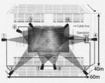
- the volleyball court has a rectangular size of 18 m ⁇ 9 m, and a free zone having a width of 3 m is provided around the rectangle.
- Each camera is arranged so that it can photograph a space having a height of 3 m in an area including at least the free zone.
- Each camera is arranged by mounting it on a tripod leveled at a predetermined position or by fixing it to a handrail.
- Each camera is calibrated in advance with the position and orientation fixed, and the position and orientation are maintained during shooting.
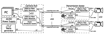
- the camera network of the motion capture camera system shown in FIG. 7 is shown in FIG. It should be noted that although 12 cameras can be connected to the camera network, 10 cameras are used in the embodiment.
- the camera network according to this embodiment includes a plurality of cameras, a transmission box, a camera hub, one or a plurality of computers, a power supply, and a waveform generator that generates a synchronization signal. Each camera is electrically connected to the transmission box, the transmission box and the camera hub are electrically connected by hybrid copper / fiber cable, and the camera hub and the computer are electrically connected. The cameras are synchronized.
- Each camera acquires an image with a resolution of 1920x1200 at 120Hz.
- Each camera has a USB3.0 interface, and USB3 to Fiber Optic Extender is used for image signal transmission.
- the transmitter box is equipped with a USB3toFiberOpticExtender Transmitter
- the camera hub is equipped with a USB3toFiberOpticExtender Receiver
- image signals are sent to the computer via the USB3toFiberOpticExtender. ..
- the computer includes a data receiving unit, a processing unit, and a storage unit. The image data received by the data receiving unit is appropriately compressed by the processing unit and stored in the storage unit.
- Each camera is mounted on a camera mounter, and the position and orientation of each camera is fixed with respect to the camera mounter.
- the internal parameters, external parameters, and distortion coefficient of the camera are obtained by the calibration, and these camera parameters are stored in the storage unit of the computer.
- the camera parameters are used for three-dimensional reconstruction of the motion of the object using each camera image.
- the motion capture camera system further includes a calibration means and one or a plurality of surveying instruments having an angle measuring function.
- the calibration means is composed of a computer (including an input unit, a calculation unit, a storage unit, an output unit, etc.).
- the calibration means acquires camera parameters for three-dimensionally reconstructing each camera image.
- the calibration according to the present embodiment is characterized in that the survey data of the survey instrument is used in the calibration calculation. More specifically, the calibration means acquires external parameters by using the position and orientation of each camera mounter in the global coordinate system, and the position and orientation of the camera mounter in the global coordinate system is one. Alternatively, it is acquired using a plurality of surveying instruments. In one aspect, the position / orientation of the camera is fixed and the surveying instrument is not used during the motion capture.
- the calibration means acquires the camera parameters by optimization calculation, and the calibration means includes an optimization calculation unit that executes optimization calculation.
- Theodolite and total station are known as high-precision surveying technology in a large outdoor space.
- Theodolite is an angle measuring instrument with a typical angle measuring function. It has a movable part (with a telescope) that can rotate horizontally and vertically, and can measure the horizontal angle and altitude angle with high accuracy. ..
- a total station is a device that has a theodolite equipped with an angle measuring function and a distance measuring function (laser measurement).
- the total station used in the experiment described later has a pan angle (horizontal angle) and tilt angle (vertical angle) accuracy of 20 seconds, and a laser range finder accuracy of ⁇ 1 mm at 28.8 m.
- the present invention relates to a motion capture camera system used for measurement in a large space, such as a surveying instrument, specifically, a theodolite or a total station, and, if necessary, a surveying instrument (reflection prism or reflection marker used for these measurements. It is possible to easily and accurately calibrate camera parameters even in a large space by configuring a camera system including
- the camera mounter When the camera mounter is composed of a surveying instrument
- the camera mounter of each camera unit consisting of one or a plurality of cameras is comprised of a theodolite or a total station surveying instrument.
- the camera mounters CM 1 , CM 2 , CM 3 and CM 4 are composed of surveying instruments.
- Each camera unit is mounted on the movable part of the surveying instrument, and can rotate in the horizontal and vertical directions integrally with the movable part when measuring the angle.
- a camera stand equipped with one or a plurality of cameras is fixedly installed on a theodolite or a total station.
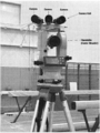
- the theodolite and the total station are mounted, for example, on a leveled tripod, and the camera unit is mounted thereon (see FIG. 4).
- the attitude / position of the camera mounter in the global coordinate system can be acquired by using the surveying technology.
- Each camera unit, a camera stand, and a plurality of cameras mounted on the camera stand are mounted on the surveying instrument.
- four cameras are radially arranged at equal angles so that the optical axes of the cameras are located in the same plane and the optical axes of all the cameras intersect at one point.
- each camera is located on the side of a regular polygonal pyramid and the optical axes of all cameras intersect at one point on the axis of the regular polygonal pyramid.
- the number of cameras in each camera unit and the arrangement mode are not limited.
- a plurality of camera mounters are configured by surveying instruments
- all the camera mounters are configured by surveying instruments.
- a portion of the plurality of camera mounters comprises a surveying instrument.
- at least one camera mounter may be a total station.
- a theodolite equipped with a camera is disclosed in, for example, Patent Documents 1-3 and Non-Patent Document 2, and is also known as a video theodolite.
- the camera in the conventional video theodolite is in a rotatable state during normal use, and the camera also rotates together with the rotation of the angle measuring unit, and uses the camera image information together with the angle measuring information.
- the angle measuring function of the surveying instrument is used only in the calibration of the camera, and the position of the camera is fixed during use (during motion capture).
- the theodolite angle measurement function is not used.
- use of the angle measuring function of the surveying instrument at the time of motion capture is not excluded, and the angle measuring function may be used in the dynamic calibration described later.
- the camera mounter is provided with a marker that can be measured by a surveying instrument
- the camera mounter is provided with a plurality of markers (characteristic points), and the marker is used by the surveying instrument.
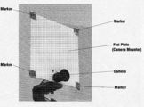
- the camera mounter includes a plate (for example, a square of 30 cm ⁇ 30 cm to 40 cm ⁇ 40 cm) having a flat surface of a predetermined shape and size, and the flat surface portion of the plate is a reflection that serves as a target for a theodolite or a total station.
- Three or more (for example, four) markers are provided.
- the camera mounters CM 1 , CM 2 , CM 3 and CM 4 are composed of a plate having a flat surface having a plurality of reflection markers.
- a camera whose relative position is fixed is mounted on the flat plate.
- each camera unit includes one camera, and the camera is fixed at the center of the width direction in the lower portion of the square flat plate.
- a flat plate that has three or more reflection markers and is fixed in its relative position to the camera is attached to the camera base (head) together with the camera, and the camera base is fixed to a tripod or the like.
- a plurality of cameras may be mounted on the camera mounter including a plate having a plurality of markers.
- the posture / position of the camera mounter (flat plate) in the global coordinate system can be acquired.
- a surveying instrument typically a total station
- a surveying instrument typically a total station having an angle measuring function and a distance measuring function for the measurement of the marker. ..
- surveying instruments other than theodolite and total station
- examples of surveying instruments other than theodolite and total station include a tripod, aluminum stuff, aluminum rod, pole, level, auto level, reflecting prism, and prism pole.
- [B] Camera Calibration Camera calibration for three-dimensional reconstruction in large space motion capture will be described.
- the three methods of the first method, the second method, and the third method will be described below.
- the first method is a known method, but the third method is a combination of the first method and the second method. Therefore, the first method will be referred to together with the description of the camera parameters.
- [B-1] General bundle adjustment using a feature point group whose position is unknown (first method) Calibration of each camera of the camera system used in this embodiment will be described.
- the bundle adjustment means that the bundle of rays from the three-dimensional feature point to the camera is optimally adjusted for both the position and orientation of the three-dimensional feature point and the camera. ..
- This optimization is generally solved as a non-linear optimization problem that minimizes reprojection error of feature points.
- the perspective projection transformation matrix based on the pinhole camera model which is the simplest camera model, is used for reprojection of the feature points.
- the matrices i A and i B that represent the internal and external parameters of the camera can be expressed as follows.
- i f x and i f y are the focal lengths in pixel units of the x and y axes on the image plane
- i c x and i c y are the principal points on the image plane (the intersection of the image plane and the optical axis).
- position of) the matrix i R is the attitude of the global coordinate system in the camera coordinate system
- i t represents the position of the origin of the global coordinate system in the camera coordinate system.
- FIG. 11 shows a projection from a three-dimensional space onto an image plane along coordinate axes commonly used in computer vision.
- the internal parameter matrix A of the camera is defined by the following formula.
- the matrix i R can be treated as i R ( i ⁇ ⁇ , i ⁇ ⁇ , i ⁇ ⁇ ) as three variables when expressed in Euler angles.
- the nonlinear least squares problem that minimizes the reprojection error of feature points in multiple cameras can be expressed as follows.
- the focal lengths i f x , i f y which are optimization variables, and the camera position i t have a relationship such that if one is fixed, the other is not determined. Therefore, either one must be fixed, or the upper and lower limits must be set narrower for each.
- the data obtained for multi-camera calibration is the pixel position in the image plane of the tie points (a group of feature points whose positions in the global coordinate system are unknown, such as the locus of the center position of the color ball) for multiple cameras.
- the position X tie of the feature point group in the global coordinate system is determined depending on the positions and orientations of the plurality of cameras.
- This bundle adjustment can be expressed as:
- the above system of nonlinear equations can be solved using the Levenberg-Marquardt method.
- This bundle adjustment can be expressed as:
- the above nonlinear equation can be solved using the Levenberg-Marquardt method or the Trust-Region-Reflective method.
- the Trust-Region-Reflective method for optimization variables, You can set a range constraint such as. Based on the obtained camera mounter position / orientation i B m , by setting the initial values of the optimization variables and narrow range constraints, the above-mentioned focal lengths i f x , i f y and camera position i t You can add surveyingly relevant constraints to the relationship.
- the distortion coefficient of the camera is an internal parameter using the OpenCV function cv :: calibrateCamera by using multiple images taken at various distances and angles for a checkerboard with known distances between grid points. Ask with.
- the internal parameters are also optimized as variables for bundle adjustment.
- optimization solver optimization was performed using the function lsqnonlin that solves the nonlinear least squares problem in the Optimization Toolbox of MATLAB.
- FIGS. 5 and 6 The characteristic points on the court and the position / orientation of the camera mounter were obtained using a surveying instrument, and the bundle position adjustment was performed for each camera to obtain the camera position / orientation.
- the camera mounter with a survey marker and the survey instrument used in the experiment are shown in FIGS. 5 and 6, respectively.
- the surveying instrument is a total station (angle surveyer / laser rangefinder), the camera mounter is a 40 cm ⁇ 40 cm flat plate, and surveying markers are provided at the four corners.
- FIG. 9 shows 18 on-court feature points (white line intersections). The position information of these feature points in the global coordinate system is acquired using a surveying instrument.
- the feature point number 0 on the court is the origin
- the X axis is the direction from the origin to the feature point number 9 on the court is positive
- the Z axis is the vertical upward direction determined by the leveling of the total station. I am trying.
- the axis of the coordinate system obtained as a result of optimization is rotated, and the three-dimensional position obtained by surveying is also translated / rotated.
- the on-court feature point whose position in the global coordinate system is known is used as the control point.
- the position / orientation of the camera mounter with surveying markers in the global coordinate system is converted into the local coordinate system of the camera mounter, which is used as the initial value of the camera external parameter matrix.
- Calibration is performed by solving the equation (5). Further, although optimization is performed for each camera based on direct measurement by the surveying instrument, bundle adjustment of a plurality of cameras may be performed based on direct measurement by the surveying instrument. This is the evaluation function Can be treated as a minimization problem.
- Non-Patent Document 1 the camera calibration data and the video motion capture system (see Non-Patent Document 1) were used to reconstruct the whole-body motions of 12 players during a volleyball game.
- the motion capture camera system according to the present embodiment can be applied to any motion measurement without being limited to the type and location of sports.
- target sports include soccer, futsal, rugby, baseball, volleyball, handball, tennis, and gymnastics.
- Examples of the shooting location include an outdoor sports field, an indoor sports field, an outdoor court, an indoor court, an arena, a dome, and a gymnasium.
- the calibration according to the present embodiment should be applied to video motion capture from a plurality of camera images for broadcasting / recording in which a cameraman manually manipulates the focal length, pan / tilt, and the like.
- These parameters are calculated by using fixed feature points (for example, points on the line or points on the goal) on elements that form a sports field or court, and feature points of unknown positions (for example, balls in ball games). All parameters of time are dynamically obtained by optimization calculation.
- position information in a global coordinate system of a plurality of immovable feature points is acquired and stored by a surveying instrument having a angle measuring function (which may have a distance measuring function).
- Fixed feature points are points on elements that form a sports field or court, such as intersections (including corners) of lines on the field or court, intersections, and points on goal posts (intersection between post and crossbar). The lower end of a part or a post) can be illustrated.
- a ball in a ball game can be exemplified as the feature point whose position information in the global coordinate system is unknown. Moreover, you may use the mark of the specific position on the uniform which the player is wearing, or the specific point of the shoes as the feature point whose position is unknown.
- the variation width of some parameters may be set small or the change speed of some parameters may be set small by using an empirical rule.
- the camera mounter may be configured by a surveying instrument having an angle measuring function, and the posture information of the camera mounter acquired by using the surveying instrument may be used for the optimization calculation.
- the time series information of the measurement value (angle) of the surveying instrument is acquired and stored, or the optimization calculator receives the measurement value of the surveying instrument in real time and The optimization calculation may be performed with.
- the point T i is the origin of the local coordinate system of the i-th angle measuring instrument
- the point Hi is the foot of the perpendicular from T i on the pole
- the axes X Ti , Y Ti , and X Ti are of the local coordinate system of the angle measuring instrument. Refers to each axis.
- the angle ⁇ i A is the angle
- the angle ⁇ i B is the angle
- Each line segment is as follows. Therefore, the vector Is as follows. If there are actual measured values for the line segments T i A and T i B using the laser rangefinder, consider the values and optimize the vector. Ask.
- the external parameter matrix i B m representing the position / orientation can be defined as follows.
- angles i ⁇ horizontalj and i ⁇ verticalj indicate the direction angle and the altitude angle to the marker measured by the angle range finder.
- the external parameter i B m is defined as follows, as in the previous section.
- the focal length of the camera and the relative extrinsic parameter matrix between the camera and the mounter it is preferable to obtain the focal length of the camera and the relative extrinsic parameter matrix between the camera and the mounter by optimization. If the focal length is obtained in advance and fixed, a proper camera position can be obtained in the field. At this time, if an angle measuring instrument is used as the camera mounter, the focal length of the camera can be obtained more accurately.
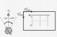
- the procedure is specifically described. First, for a leveled surveying pole, a level coordinate system is used to define the global coordinate system as described above. Next, the surveying pole is photographed by moving it at regular intervals (1 ° step, ⁇ 10 ° range). This allows control points to be defined on the survey pole (see Figure 15). You can get the position of the control point guaranteed to the accuracy of theodolite.
- the camera system includes a camera unit including a plurality of (for example, 4 or 2) cameras, and each camera unit is mounted on a surveying instrument (theodolite or total station). Each camera unit is mounted on the movable part of the surveying instrument, and can rotate in the horizontal and vertical directions integrally with the movable part when measuring the angle. In one aspect, one camera unit is mounted on the total station and another camera unit is mounted on the theodolite. Of course, a plurality of camera units may be mounted in a plurality of total stations.
- i indicates the theodolite serial number
- j indicates the j-th camera mounted on the i-th theodolite. Note that in section [C] above, i indicates the camera serial number, and the camera mounter (including the theodolite) is assigned the camera serial number.
- [D-1] Theodolite coordinate system in the world coordinate system
- the acquisition of the homogeneous conversion matrix from the world coordinate system to the theodolite coordinate system will be described.
- the theodolite and total station are mounted on a tripod.
- Set each tripod so that the field of view of each camera includes the measurement range.
- the surveying pole is a well-known pole generally used in surveying, and for example, red and white stripes are formed with a width of 10 cm.
- the upper measurement point on the pole is A, and the lower measurement point is B.
- the coordinate system of the total station is the coordinate system ⁇ 0 ⁇ . Counterclockwise with the theodolite coordinate system as the coordinate system ⁇ 1 ⁇ , ⁇ 2 ⁇ , ..., ⁇ M ⁇ .
- M is the theodolite number.
- the Yaw angle between the camera mounters is measured using the theodolites or each total station.
- the Yaw angle from the coordinate system ⁇ 0 ⁇ to the coordinate system ⁇ 1 ⁇ is represented by ⁇ 01 .
- the tip of the pendulum weight of the theodolite or total station that is the target is the target (characteristic point).
- Each camera unit is equipped with four fixed cameras on a horizontal plane that can rotate integrally with the Yaw rotation of the theodolite or total station.
- the camera is fan-shaped with a sector angle of 22.5 °.
- the axis is symmetric with respect to the zx plane. Each axis Rotate around 9.65 °.
- the camera is squeezed open and focused on ⁇ .
- the amount of light is controlled by the shutter speed. Show the checkerboard to the camera in 15 different positions and orientations.
- the distortion-free image I ij * is generated from I ij using P ij in the following format,
- the distortion-free image is the three-dimensional position of the camera coordinate system. To Indicate.
- An optimization calculation is performed so as to satisfy the above two equations, and a homogeneous transformation matrix from the theodolite coordinate system to the camera coordinate system. To get. Similarly, the simultaneous conversion matrix is acquired for the next camera j, and the same conversion matrix is acquired for the next theodolite to acquire the simultaneous conversion matrix.
- the result of the calibration according to this embodiment is represented by the following three formulas.
- the motion capture system is a so-called video motion capture system (see Non-Patent Document 1), and three-dimensional reconstruction is performed from joint positions estimated using deep learning from images of a plurality of cameras acquired by the motion capture camera system.
- the target does not need to attach any marker or sensor, and the measurement space is not limited.
- Motion capture is performed completely unconstrained from the images of multiple RGB cameras. In principle, if images can be acquired from indoor living spaces to large outdoor sports fields, motion measurement is possible. It is a technology.
- the motion capture system described below is an example, and the motion capture used with the motion capture camera system according to the present invention is not limited, and other methods may be adopted.
- each image includes multiple people.
- the joint positions of one person selected from the plurality of persons or an arbitrary number of a plurality of persons are acquired.
- one image contains multiple people, for example, PAF and PCM (Zhe Cao, Tomas Simon, Shih-En Wei, and Yaser Sheikh. Realtime multi-person 2d pose estimation using part affinity fields.InInProceedings By using IEEE Conference on Computer Vision and Pattern Recognition.CVPR 2017, 2017.), joint position can be acquired for each person at the same time.
- the object has a link structure or an articulated structure.
- the object is typically a human with a skeletal structure, but the object may be a robot.
- the video motion capture system uses the motion capture camera system that captures the motion of the target and the degree of certainty of the position of the feature points (Keypoints) including joint positions in color intensity based on the images captured by the camera system.
- the heat map acquisition unit that acquires the heat map information to be displayed, the joint position acquisition unit that acquires the target joint position using the heat map information acquired by the heat map acquisition unit, and the joint that is acquired by the joint position acquisition unit
- a smoothing processing unit that smoothes the position
- a storage unit that stores the skeletal structure of the target body, time series data of images acquired by the video system, time series data of the joint positions acquired by the joint position acquisition unit, and the like.
- the motion capture / camera system includes a plurality of cameras, and a plurality of synchronized cameras capture the motion of the subject, and each camera outputs an RGB image at a predetermined frame rate.
- a plurality of camera images acquired at the same time are transmitted to the heat map acquisition unit.
- the heat map acquisition unit generates a heat map based on the RGB image.
- the heat map represents the spatial distribution of the likelihood of the position of the feature points on the body.
- the heat map acquisition unit generates a two-dimensional or three-dimensional spatial distribution of the likelihood of the likelihood of the position of the feature points (keypoints) on the body including each joint position based on the input image, and calculates the likelihood of the likelihood. Display the spatial distribution in heat map format.
- the heat map acquisition unit typically uses a convolutional neural network (CNN) to calculate the position (typically a joint position) of a feature point on the target body from a single input image as a heat map. Estimate as.
- CNN convolutional neural network
- the generated heat map information is transmitted to the joint position acquisition unit, and the joint position acquisition unit acquires the joint position.
- the joint position acquisition unit estimates the joint position candidate using the heat map information acquired from the heat map acquisition unit, and executes the optimization calculation based on the inverse kinematics using the joint position candidate to calculate the skeleton model. Update the joint angle and joint position.
- the joint position acquisition unit estimates the joint position candidate based on the heat map data, and the joint position candidate inverse motion that performs the optimization calculation based on the inverse kinematics using the joint position candidate to calculate the joint angle.
- a forward kinematics calculation unit that performs forward kinematics calculation using the calculated joint angle to calculate the joint position.
- the acquired joint position data is stored in the storage unit as time series data of the joint position.
- the acquired joint position data is transmitted to the smoothing processing unit, and the smoothed joint position and the joint angle are acquired.
- the smoothed joint position acquisition unit of the smoothing processing unit performs smoothing processing on the acquired joint position using the joint position in the past frame to smooth the temporal movement of the joint position.
- the target pose is determined based on the smoothed joint position or joint angle and the skeletal structure of the target body, and the target motion made up of time series data of the pose is displayed on the display.
- FIG. 17 exemplifies the processing steps of motion analysis using motion capture.
- the target motion is acquired by the motion capture according to this embodiment.
- Time series data of the acquired joint angle and joint position is acquired.
- the joint torque is obtained by inverse dynamics calculation, and the joint torque is used to optimize the wire tension in the musculoskeletal model including the wire imitating a muscle (quadratic programming or linear programming).
- Method calculate the muscle activity using the wire tension, generate a musculoskeletal image with colors assigned according to the degree of muscle activity, and visualize the musculoskeletal with muscle activity.
- the image is output at a predetermined frame rate and displayed on the display as a moving image. In this way, it is possible to automatically and efficiently perform the process of capturing the motion of the target, the acquisition of the three-dimensional pose of the target during the motion, and the estimation and visualization of the muscle activity required for the motion.
Landscapes
- Engineering & Computer Science (AREA)
- Multimedia (AREA)
- Signal Processing (AREA)
- Computer Vision & Pattern Recognition (AREA)
- Physics & Mathematics (AREA)
- General Physics & Mathematics (AREA)
- Theoretical Computer Science (AREA)
- Studio Devices (AREA)
- Image Analysis (AREA)
- Length Measuring Devices By Optical Means (AREA)
Abstract
モーションキャプチャの撮像空間が大空間であっても簡便かつ高精度にカメラのキャリブレーションを行う。複数のカメラ画像を3次元再構成するためのカメラパラメータを取得するキャリブレーション方法であって、前記カメラパラメータは、グローバル座標系における各カメラの位置・姿勢を表す外部パラメータを含み、測角機能を備えた1つあるいは複数の測量機を用いて、グローバル座標系における各カメラマウンタの位置及び姿勢を取得すること、グローバル座標系における各カメラマウンタの位置及び姿勢を用いて前記外部パラメータを取得すること、を含む。
Description
本発明は、モーションキャプチャ用のカメラシステムに関するものである。
モーションキャプチャ技術は、様々な運動計測に広く利用されている。しかしながら、チームスポーツにおいて、試合中の各選手の運動をキャプチャして動作解析を行うようなことは行われていない。例えば、サッカー、ラグビー、野球、バレーボール、ハンドボール等のスポーツの試合の動画を取得して、取得した動画に基づいて各選手の動作解析を行うことは行われていない。
チームスポーツにおいて、試合中の各選手の運動をキャプチャして動作解析を行うためには、(a)モーションキャプチャが選手のパフォーマンスを低下させないこと、(b)モーションキャプチャがサポーティングオペレーション(テレビ放映、チームスタッフ、観客等)の妨げとならないこと、(c)大記憶容量、(d)距離が離れたハイスピードカメラ間の同期、(e)大量のデータをリアルタイムで受信する能力、(f)長時間稼働できる性能を備えた安定的なシステム、(g)正確な3次元再構成のためのカメラキャリブレーション、等の条件をクリアする必要がある。
従来の典型的なモーションキャプチャ技術としては、光学式モーションキャプチャや慣性センサを用いたモーションキャプチャが知られている。これらのモーションキャプチャは、反射マーカや慣性センサを対象の身体に装着するための計測準備に時間を要するという欠点があり、さらに、該マーカや該センサが対象の円滑な動きの妨げになり得ることから試合中の各選手の動作取得に用いることができない。また、これらのモーションキャプチャは計測空間も限定的である。赤外線光源を用いた光学式モーションキャプチャでは、外光の影響を受けないカメラで囲まれた空間で計測を行う必要があり、センサデータを無線で受信する場合には、無線信号が届く限られた空間で計測する必要があった。
最近では、いわゆるマーカレスモーションキャプチャ技術が登場している。例えば、ビデオモーションキャプチャ技術(非特許文献1)は、複数台のRGBカメラの映像から完全非拘束でモーションキャプチャを行うもので、屋内の居住空間から、屋外でのスポーツフィールドの広い空間まで、原理的には映像が取得できれば、動作計測が可能となる技術である。
複数のカメラを用いたモーションキャプチャにおいては、複数のカメラ画像を3次元再構成するためのカメラパラメータを取得する必要がある。カメラパラメータには、レンズの歪みなどの光学的パラメータ、焦点距離や光学的中心等の内部パラメータ、カメラが設置された空間におけるカメラの位置・姿勢を表す外部パラメータがある。従来のカメラキャリブレーションは、これら全てのパラメータのキャリブレーションを、既知の形状や寸法のキャリブレーション器具(チェッカーボードやキャリブレーションワンド等)を1台または複数台のカメラで撮影することで行っている。
しかしながら、スポーツフィールドのような広い空間では、動作計測のための3次元再構成を行うためには、対象から遠く離れたカメラの高精度なキャリブレーションが必要となり、従来のモーションキャプチャシステムとは異なるシステム構成や比較的近距離でのカメラキャリブレーションとは異なるキャリブレーション法が必要となる。カメラパラメータのうち、レンズ歪みを含む光学パラメータ及び焦点距離などの内部パラメータのキャリブレーションは、カメラとレンズが確定すれば事前にキャリブレーションを行うことができるが、カメラの空間における位置姿勢に関する外部パラメータのキャリブレーションは、カメラが設置された現場で行う必要がある。
スポーツフィールドや屋外における人やロボットの計測は、計測領域が大空間となるという特徴がある。従来のように、キャリブレーション器具(チェッカーボードやキャリブレーションワンド等)を用いてキャリブレーションを行うことは原理的に可能であるが、キャリブレーションの精度は撮像素子画の画素数に依存するため、撮影対象までの距離が数十メートルとなると、キャリブレーション精度が低下し、モーションキャプチャにおける三次元再構成には適しない。従来に比べて大型のキャリブレーション器具(例えば、大型のチェッカーボードや大型のキャリブレーションワンド等)を用意し、これを使用することも考えられるが、カメラの撮影範囲が水平方向及び高さ方向において広範囲に及ぶ場合には、このような広範囲をカバーするように大型のキャリブレーション器具を異なる位置及び姿勢で移動させることは現実的でない。
T. Ohashi, Y. Ikegami, K. Yamamoto, W. Takano and Y. Nakamura, Video Motion Capture from the Part Confidence Maps of Multi-Camera Images by Spatiotemporal Filtering Using the Human Skeletal Model, 2018 IEEE/RSJ International Conference on Intelligent Robots and Systems (IROS), Madrid, 2018, pp. 4226-4231.
ハイブリッドビデオセオドライトシステムの人体の歩行解析への応用 穴井 哲治、近津 博文 写真測量とリモートセンシング40巻(2001)2号
本発明は、モーションキャプチャの撮像空間が大空間であっても簡便かつ高精度にカメラのキャリブレーションを行うことを目的とするものである。
本発明に係るモーションキャプチャ・カメラシステムは、
1つあるいは複数のカメラからなる複数のカメラユニットと、
各カメラユニットが搭載される複数のカメラマウンタと、
各カメラ画像を3次元再構成するためのカメラパラメータを取得するキャリブレーション手段と、
測角機能を備えた1つあるいは複数の測量機と、
を備え、
前記カメラパラメータは、グローバル座標系における各カメラの位置・姿勢を表す外部パラメータを含み、
前記キャリブレーション手段は、グローバル座標系における各カメラマウンタの位置及び姿勢を用いて前記外部パラメータを取得するものであり、前記グローバル座標系におけるカメラマウンタの位置及び姿勢は、前記1つあるいは複数の測量機を用いて取得される。
1つの態様では、前記1つあるいは複数の測量機のうちの1つあるいは複数の測量機は、測距機能を備えている。
測角機能を備えた測量機としては、セオドライト、トータルステーションを例示することができる。
測角機能及び測距機能を備えた測量機としては、トータルステーションを例示することができる。
1つあるいは複数のカメラからなる複数のカメラユニットと、
各カメラユニットが搭載される複数のカメラマウンタと、
各カメラ画像を3次元再構成するためのカメラパラメータを取得するキャリブレーション手段と、
測角機能を備えた1つあるいは複数の測量機と、
を備え、
前記カメラパラメータは、グローバル座標系における各カメラの位置・姿勢を表す外部パラメータを含み、
前記キャリブレーション手段は、グローバル座標系における各カメラマウンタの位置及び姿勢を用いて前記外部パラメータを取得するものであり、前記グローバル座標系におけるカメラマウンタの位置及び姿勢は、前記1つあるいは複数の測量機を用いて取得される。
1つの態様では、前記1つあるいは複数の測量機のうちの1つあるいは複数の測量機は、測距機能を備えている。
測角機能を備えた測量機としては、セオドライト、トータルステーションを例示することができる。
測角機能及び測距機能を備えた測量機としては、トータルステーションを例示することができる。
1つの態様では、前記複数のカメラマウンタの一部あるいは全部は、前記測量機である。
1つの態様では、1つのカメラマウンタがトータルステーションから構成され、残りのカメラマウンタがセオドライトから構成される。
カメラマウンタを構成する測量機は整準されている。
1つの態様では、1つのカメラマウンタがトータルステーションから構成され、残りのカメラマウンタがセオドライトから構成される。
カメラマウンタを構成する測量機は整準されている。
1つの態様では、前記複数のカメラマウンタの一部あるいは全部は、前記測量機によって測量可能な複数のマーカ(特徴点)を備えている。
1つの態様では、全てのカメラマウンタが、マーカを備えたカメラマウンタである。
1つの態様では、前記カメラマウンタは、3つ以上のマーカ(例えば、4つの測量マーカ)を備えた平面を有している。
1つの態様では、全てのカメラマウンタが、マーカを備えたカメラマウンタである。
1つの態様では、前記カメラマウンタは、3つ以上のマーカ(例えば、4つの測量マーカ)を備えた平面を有している。
1つの態様では、前記キャリブレーション手段は、各カメラの撮像空間に位置する複数の特徴点のグローバル座標系での位置情報(3次元位置情報)と、各カメラ画像での各特徴点の位置情報(2次元位置情報)と、を用いるものであり、
前記複数の特徴点のグローバル座標系での位置情報は、前記測量機を用いて取得される。
1つの態様では、前記特徴点は、各カメラの撮像空間に位置する不動点であり、例えば、コート上のラインの交点(角部を含む)や交差部や、ゴールポスト上の点(ポストとクロスバーの交差部やポストの下端)を特徴点として利用することができる。
1つの態様では、前記特徴点の3次元位置情報及び2次元位置情報は、外部パラメータを取得する際の最適化計算に用いられる。
前記複数の特徴点のグローバル座標系での位置情報は、前記測量機を用いて取得される。
1つの態様では、前記特徴点は、各カメラの撮像空間に位置する不動点であり、例えば、コート上のラインの交点(角部を含む)や交差部や、ゴールポスト上の点(ポストとクロスバーの交差部やポストの下端)を特徴点として利用することができる。
1つの態様では、前記特徴点の3次元位置情報及び2次元位置情報は、外部パラメータを取得する際の最適化計算に用いられる。
1つの態様では、前記キャリブレーション手段は、各カメラマウンタ座標系における当該カメラマウンタに搭載された各カメラの位置・姿勢(例えば、カメラマウントに対するカメラの位置・姿勢が既知の場合)を用いる。
1つの態様では、前記キャリブレーション手段は、各カメラマウンタ座標系における当該カメラマウンタに搭載された各カメラの位置・姿勢を取得する手段を備える。
1つの態様では、前記カメラマウンタは前記測量機から構成されており、
前記カメラマウンタ座標系における前記カメラの位置及び姿勢の取得において、前記測量機が用いられる。
1つの態様では、各カメラマウンタ座標系における当該カメラマウンタに搭載された各カメラの位置・姿勢は既知ないし予め取得されている。
1つの態様では、前記キャリブレーション手段は、各カメラマウンタ座標系における当該カメラマウンタに搭載された各カメラの位置・姿勢を取得する手段を備える。
1つの態様では、前記カメラマウンタは前記測量機から構成されており、
前記カメラマウンタ座標系における前記カメラの位置及び姿勢の取得において、前記測量機が用いられる。
1つの態様では、各カメラマウンタ座標系における当該カメラマウンタに搭載された各カメラの位置・姿勢は既知ないし予め取得されている。
1つの態様では、前記キャリブレーション手段は、最適化計算によって前記外部パラメータを取得する。
1つの態様では、最適化計算において、前記グローバル座標系におけるカメラマウンタの位置及び姿勢、及び、前記特徴点の前記3次元位置情報及び前記2次元位置情報が用いられる。
1つの態様では、前記最適化計算において、グローバル座標系の位置情報が未知の1つあるいは複数の特徴点に対応する各カメラ画像の位置情報が用いられる。
1つの態様では、最適化計算において、前記グローバル座標系におけるカメラマウンタの位置及び姿勢、及び、前記特徴点の前記3次元位置情報及び前記2次元位置情報が用いられる。
1つの態様では、前記最適化計算において、グローバル座標系の位置情報が未知の1つあるいは複数の特徴点に対応する各カメラ画像の位置情報が用いられる。
1つの態様において、前記カメラパラメータは、光学パラメータ、内部パラメータを含み、前記キャリブレーション手段は、最適化計算によって前記外部パラメータ、前記光学パラメータ、内部パラメータの一部あるいは全部を取得する。
光学パラメータ及び内部パラメータは、従来手法(キャリブレーション器具を用いる)によって取得してもよい。
例えば、前記カメラマウンタが前記測量機から構成されている場合には、光学パラメータ及び内部パラメータの取得において、前記測量機を用いてもよい。
外部パラメータの取得において、取得した光学パラメータ及び内部パラメータの一部あるいは全部を用いてもよい。
光学パラメータ及び内部パラメータは、従来手法(キャリブレーション器具を用いる)によって取得してもよい。
例えば、前記カメラマウンタが前記測量機から構成されている場合には、光学パラメータ及び内部パラメータの取得において、前記測量機を用いてもよい。
外部パラメータの取得において、取得した光学パラメータ及び内部パラメータの一部あるいは全部を用いてもよい。
本発明は、1つあるいは複数のカメラからなる複数のカメラユニットと、
各カメラユニットが搭載される複数のカメラマウンタと、
を備えたモーションキャプチャ・カメラシステムにおいて、前記複数のカメラ画像を3次元再構成するためのカメラパラメータを取得するキャリブレーション方法であって、
前記カメラパラメータは、グローバル座標系における各カメラの位置・姿勢を表す外部パラメータを含み、
測角機能を備えた1つあるいは複数の測量機を用いて、グローバル座標系における各カメラマウンタの位置及び姿勢を取得すること、
グローバル座標系における各カメラマウンタの位置及び姿勢を用いて前記外部パラメータを取得すること、
を含む。
各カメラユニットが搭載される複数のカメラマウンタと、
を備えたモーションキャプチャ・カメラシステムにおいて、前記複数のカメラ画像を3次元再構成するためのカメラパラメータを取得するキャリブレーション方法であって、
前記カメラパラメータは、グローバル座標系における各カメラの位置・姿勢を表す外部パラメータを含み、
測角機能を備えた1つあるいは複数の測量機を用いて、グローバル座標系における各カメラマウンタの位置及び姿勢を取得すること、
グローバル座標系における各カメラマウンタの位置及び姿勢を用いて前記外部パラメータを取得すること、
を含む。
1つの態様では、前記複数のカメラマウンタの一部あるいは全部は、前記測量機であり、複数の計測点(特徴点)の測量データを用いてグローバル座標系における各カメラマウンタの位置及び姿勢を取得する。
1つの態様では、前記複数の計測点は、各測量機から測量可能な2つの特徴点A、B(間隔が既知、例えば、垂直の測量用ポール上の点Aと点B)と、各カメラマウンタ上の特徴点(例えば、振り子錘の下端)と、を含む。
測量機で前記2つの特徴点A、Bを測量することで、各カメラマウンタ座標系の原点から点A、点Bまでのベクトルを取得することができる。例えば、該ベクトルの水平角と同じ水平角の水平軸をz軸、垂直軸をx軸とする。
各測量機で他のカメラマウンタ上の特徴点を測量することで、各マウンタ座標系間の角度を取得することができる。
グローバル座標系のz軸とx軸を、1つのマウンタの座標系のz軸とx軸に一致させ、点Aと点B間の距離と上記設定情報を用いることで、三角法によって、各カメラマウンタのグローバル座標系における位置及び姿勢を取得する。
1つの態様では、前記複数の計測点は、各測量機から測量可能な2つの特徴点A、B(間隔が既知、例えば、垂直の測量用ポール上の点Aと点B)と、各カメラマウンタ上の特徴点(例えば、振り子錘の下端)と、を含む。
測量機で前記2つの特徴点A、Bを測量することで、各カメラマウンタ座標系の原点から点A、点Bまでのベクトルを取得することができる。例えば、該ベクトルの水平角と同じ水平角の水平軸をz軸、垂直軸をx軸とする。
各測量機で他のカメラマウンタ上の特徴点を測量することで、各マウンタ座標系間の角度を取得することができる。
グローバル座標系のz軸とx軸を、1つのマウンタの座標系のz軸とx軸に一致させ、点Aと点B間の距離と上記設定情報を用いることで、三角法によって、各カメラマウンタのグローバル座標系における位置及び姿勢を取得する。
1つの態様では、前記複数のカメラマウンタの一部あるいは全部は、前記測量機によって測量可能な複数のマーカ(特徴点)を備えており、複数のマーカの測量データを用いてグローバル座標系におけるカメラマウンタの位置及び姿勢を取得する。
1つの態様では、前記カメラマウンタは、3つ以上のマーカ(例えば、4つの測量マーカ)を備えた平面を有している。
1つの態様では、3つ以上のマーカ間の距離が既知であり、かつ、これらのマーカが垂直面上に設けてあり、測量機(例えば、測角機能及び測距機能を備える)で3つのマーカを測量し、測量機の中心を原点としてグローバル座標系を設定することで、測量情報と三角法を用いることで、各カメラマウンタのグローバル座標系における位置及び姿勢を取得する。
1つの態様では、前記カメラマウンタは、3つ以上のマーカ(例えば、4つの測量マーカ)を備えた平面を有している。
1つの態様では、3つ以上のマーカ間の距離が既知であり、かつ、これらのマーカが垂直面上に設けてあり、測量機(例えば、測角機能及び測距機能を備える)で3つのマーカを測量し、測量機の中心を原点としてグローバル座標系を設定することで、測量情報と三角法を用いることで、各カメラマウンタのグローバル座標系における位置及び姿勢を取得する。
1つの態様では、前記外部パラメータの取得において、各カメラの撮像空間に位置する複数の特徴点のグローバル座標系での位置情報と、各カメラ画像での各特徴点の位置情報と、が用いられ、
前記複数の特徴点のグローバル座標系での位置情報は、前記測量機を用いて取得される。
1つの態様では、前記特徴点は、各カメラの撮像空間に位置する不動点であり、例えば、コート上のラインの交点(角部を含む)や交差部や、ゴールポスト上の点(ポストとクロスバーの交差部やポストの下端)を特徴点として利用することができる。
1つの態様では、前記特徴点の3次元位置情報及び2次元位置情報は最適化計算に用いられる。
前記複数の特徴点のグローバル座標系での位置情報は、前記測量機を用いて取得される。
1つの態様では、前記特徴点は、各カメラの撮像空間に位置する不動点であり、例えば、コート上のラインの交点(角部を含む)や交差部や、ゴールポスト上の点(ポストとクロスバーの交差部やポストの下端)を特徴点として利用することができる。
1つの態様では、前記特徴点の3次元位置情報及び2次元位置情報は最適化計算に用いられる。
1つの態様では、前記外部パラメータの取得において、各カメラマウンタ座標系における当該カメラマウンタに搭載された各カメラの位置・姿勢を用いる。
1つの態様では、前記キャリブレーション手段は、各カメラマウンタ座標系における当該カメラマウンタに搭載された各カメラの位置・姿勢を取得する手段を備える。
1つの態様では、前記カメラマウンタは前記測量機から構成されており、
前記カメラマウンタ座標系における前記カメラの位置及び姿勢は、前記測量機を用いて取得される。
1つの態様では、前記測量機を用いてカメラマウンタ座標系の位置が既知な複数の特徴点を設定し(図15参照)、
各カメラ画像における各特徴点の位置情報を取得し、
前記特徴点のカメラマウンタ座標系の位置情報とカメラ画像における位置情報を用いて、前記カメラマウンタ座標系における前記カメラの位置及び姿勢を取得する。
1つの態様では、各カメラマウンタ座標系における当該カメラマウンタに搭載された各カメラの位置・姿勢は既知ないし予め取得されている。
1つの態様では、前記キャリブレーション手段は、各カメラマウンタ座標系における当該カメラマウンタに搭載された各カメラの位置・姿勢を取得する手段を備える。
1つの態様では、前記カメラマウンタは前記測量機から構成されており、
前記カメラマウンタ座標系における前記カメラの位置及び姿勢は、前記測量機を用いて取得される。
1つの態様では、前記測量機を用いてカメラマウンタ座標系の位置が既知な複数の特徴点を設定し(図15参照)、
各カメラ画像における各特徴点の位置情報を取得し、
前記特徴点のカメラマウンタ座標系の位置情報とカメラ画像における位置情報を用いて、前記カメラマウンタ座標系における前記カメラの位置及び姿勢を取得する。
1つの態様では、各カメラマウンタ座標系における当該カメラマウンタに搭載された各カメラの位置・姿勢は既知ないし予め取得されている。
1つの態様では、最適化計算によって前記外部パラメータを取得する。
1つの態様では、最適化計算において、前記グローバル座標系におけるカメラマウンタの位置及び姿勢、及び、前記特徴点の3次元位置情報及び2次元位置情報が用いられる。
1つの態様では、前記最適化計算において、グローバル座標系の位置情報が未知の1つあるいは複数の特徴点に対応する各カメラ画像の位置情報が用いられる。
1つの態様では、各カメラは同期されており、各カメラで異なる位置・姿勢にあるキャリブレーション器具を撮影し、キャリブレーショ器具上の複数の特徴点の各カメラ画像での位置情報が用いられる。
1つの態様では、最適化計算において、前記グローバル座標系におけるカメラマウンタの位置及び姿勢、及び、前記特徴点の3次元位置情報及び2次元位置情報が用いられる。
1つの態様では、前記最適化計算において、グローバル座標系の位置情報が未知の1つあるいは複数の特徴点に対応する各カメラ画像の位置情報が用いられる。
1つの態様では、各カメラは同期されており、各カメラで異なる位置・姿勢にあるキャリブレーション器具を撮影し、キャリブレーショ器具上の複数の特徴点の各カメラ画像での位置情報が用いられる。
1つの態様において、前記カメラパラメータは、光学パラメータ、内部パラメータを含み、前記キャリブレーション手段は、最適化計算によって前記外部パラメータ、前記光学パラメータ、内部パラメータの一部あるいは全部を取得する。
光学パラメータ及び内部パラメータは、従来手法(キャリブレーション器具を用いる)によって取得してもよい。
例えば、前記カメラマウンタが前記測量機から構成されている場合には、光学パラメータ及び内部パラメータの取得において、前記測量機を用いてもよい。
外部パラメータの取得において、取得した光学パラメータ及び内部パラメータの一部あるいは全部を用いてもよい。
光学パラメータ及び内部パラメータは、従来手法(キャリブレーション器具を用いる)によって取得してもよい。
例えば、前記カメラマウンタが前記測量機から構成されている場合には、光学パラメータ及び内部パラメータの取得において、前記測量機を用いてもよい。
外部パラメータの取得において、取得した光学パラメータ及び内部パラメータの一部あるいは全部を用いてもよい。
本発明は、カメラのキャリブレーションにおいて、測量機で計測した高精度の測量データを用いることで、モーションキャプチャの撮像空間が大空間であっても簡便かつ高精度にカメラのキャリブレーションを行うことができる。
したがって、屋内外スポーツフィールド、屋内外コート、アリーナ、ドーム、体育館等で行われるスポーツの試合を撮影することで、試合中の各選手の運動を3次元再構成してモーションキャプチャを行い、動作解析を行うことができる。
したがって、屋内外スポーツフィールド、屋内外コート、アリーナ、ドーム、体育館等で行われるスポーツの試合を撮影することで、試合中の各選手の運動を3次元再構成してモーションキャプチャを行い、動作解析を行うことができる。
[A]モーションキャプチャ・カメラシステム
[A-1]全体構成
本実施形態に係るモーションキャプチャ・カメラシステムは、スポーツフィールドやアリーナ等の大空間で行われるチームスポーツを複数のカメラで撮影するものであり、各カメラで取得された撮影画像を用いて各選手のモーションキャプチャを行うものである。本実施形態で用いるモーションキャプチャは、ビデオモーションキャプチャ技術(非特許文献1)であり、その具体的な内容は後述する。
[A-1]全体構成
本実施形態に係るモーションキャプチャ・カメラシステムは、スポーツフィールドやアリーナ等の大空間で行われるチームスポーツを複数のカメラで撮影するものであり、各カメラで取得された撮影画像を用いて各選手のモーションキャプチャを行うものである。本実施形態で用いるモーションキャプチャは、ビデオモーションキャプチャ技術(非特許文献1)であり、その具体的な内容は後述する。
モーションキャプチャ・カメラシステムは、1つあるいは複数のカメラからなる複数のカメラユニットと、各カメラユニットが搭載される複数のカメラマウンタと、を備える。例えば、図1は、サッカーの試合を撮影するモーションキャプチャ・カメラシステムの概念図であり、4台のカメラを備えた4台のカメラユニットがサッカーコートを囲むように配置される。各カメラから対象である選手までの距離は数十メートルとなる。
図1に示すモーションキャプチャ・カメラシステムは、4つのカメラユニットCU1、CU2、CU3、CU4を備え、カメラユニットCU1は4つのカメラC11、C12、C13、C14、カメラユニットCU2は4つのカメラC21、C22、C23、C24、カメラユニットCU3は4つのカメラC31、C32、C33、C34、カメラユニットCU4は4つのカメラC41、C42、C43、C44を備えている。カメラユニットCU1はカメラマウンタCM1に搭載されており、カメラユニットCU2はカメラマウンタCM2に搭載されており、カメラユニットCU3はカメラマウンタCM3に搭載されており、カメラユニットCU4はカメラマウンタCM4に搭載されている。図1では便宜上、4つのカメラユニットを示したが、実際には、より多くのカメラユニットが配置され得ることになるであろう。なお、1台のカメラユニットに搭載されるカメラの数は限定されない。
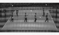
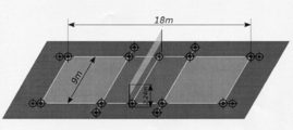
図2は、バレーボールの試合を撮影するモーションキャプチャ・カメラシステムの概念図であり、1台のカメラを備えた4台のカメラユニットがバレーボールコートを囲むように配置される。図2に示すように、モーションキャプチャ・カメラシステムは、4つのカメラユニットCU1、CU2、CU3、CU4を備え、カメラユニットCU1は1つのカメラC11、カメラユニットCU2は1つのカメラC21、カメラユニットCU3は1つのカメラC31、カメラユニットCU4は1つのカメラC41を備えている。カメラユニットCU1はカメラマウンタCM1に搭載されており、カメラユニットCU2はカメラマウンタCM2に搭載されており、カメラユニットCU3はカメラマウンタCM3に搭載されており、カメラユニットCU4はカメラマウンタCM4に搭載されている。なお、1台のカメラユニットに搭載されるカメラの数は限定されない。
後述する実験例では、図7に示すように、1台のカメラを備えた10台カメラユニットがバレーボールコートを囲むように配置される。バレーボールコートの寸法は18m×9mの長方形であり、その周囲に幅3mのフリーゾーンが設けてある。各カメラは、少なくも、フリーゾーンを含む領域で高さ3mの空間を撮影できるように配置される。各カメラは、所定位置に整準した三脚に搭載したり、手すりに固定することで配置される。各カメラは位置・姿勢を固定した状態で事前にキャリブレーションが行われ、撮影中は位置・姿勢が維持される。
図7で示したモーションキャプチャ・カメラシステムのカメラネットワークを図3に示す。カメラネットワークは12台のカメラが接続可能であるが、実施例では10台のカメラが用いている点に留意されたい。本実施形態に係るカメラネットワークは複数台のカメラと、送信ボックスと、カメラハブと、1台あるいは複数台のコンピュータと、電源と、同期信号を生成する波形発生器と、を備えている。各カメラは送信ボックスと電気的に接続されており、送信ボックスとカメラハブは、hybrid copper/fiber cableで電気的に接続されており、カメラハブとコンピュータは電気的に接続されている。各カメラは同期している。
各カメラは、120Hzで解像度1920x1200の画像を取得する。各カメラはUSB3.0インターフェースを備えており、画像信号の伝送には、USB3 to Fiber Optic Extenderが用いられる。送信ボックスには、USB3 to Fiber Optic ExtenderのTransmitterが設けられ、カメラハブには、USB3 to Fiber Optic ExtenderのReceiverが設けてあり、画像信号は、USB3 to Fiber Optic Extenderを介してコンピュータに送信される。コンピュータは、データ受信部、処理部、記憶部を備えており、データ受信部で受信された画像データは、処理部で適宜データ圧縮されて、記憶部に格納される。
各カメラは、カメラマウンタに搭載されており、カメラマウンタに対して各カメラの位置・姿勢が固定されている。キャリブレーションによって、カメラの内部パラメータ、外部パラメータ、歪み係数が得られており、これらのカメラパラメータはコンピュータの記憶部に格納される。カメラパラメータは、各カメラ画像を用いた対象の運動の3次元再構成に用いられる。
本実施形態に係るモーションキャプチャ・カメラシステムは、さらに、キャリブレーション手段と、測角機能を備えた1つあるいは複数の測量機と、を備えている。キャリブレーション手段は、コンピュータ(入力部、演算部、記憶部、出力部等を備える)から構成される。キャリブレーション手段は、各カメラ画像を3次元再構成するためのカメラパラメータを取得する。本実施形態に係るキャリブレーションは、キャリブレーションの計算において、測量機の測量データを用いる点に特徴を備えている。より具体的には、該キャリブレーション手段は、グローバル座標系における各カメラマウンタの位置及び姿勢を用いて外部パラメータを取得するものであり、前記グローバル座標系におけるカメラマウンタの位置及び姿勢は、1つあるいは複数の測量機を用いて取得される。1つの態様では、モーションキャプチャ時には、カメラの位置・姿勢は固定され、測量機は用いない。典型的には、キャリブレーション手段は、最適化計算によってカメラパラメータを取得するものであり、キャリブレーション手段は、最適化計算を実行する最適化計算部を含んでいる。
屋外の広い空間における高精度な測量技術として、セオドライトやトータルステーションが知られている。セオドライトは代表的な測角機能を備えた角度測量機であり、水平回動・上下回動可能な可動部(望遠鏡を備える)を備え、水平角・高度角を高精度で計測することができる。トータルステーションは、測角機能を備えたセオドライトに測距機能(レーザ計測)が備わった機器である。後述する実験で用いたトータルステーションは、パン角度(水平角度)及びチルト角度(垂直角度)の精度は、20 secondsであり、レーザレンジファインダの精度は、28.8mにおいて±1mmである。
本発明は、大空間における計測に用いるモーションキャプチャ・カメラシステムにおいて、測量機、具体的には、セオドライトやトータルステーション、及び、必要に応じて、これらの計測に用いられる測量器具(反射プリズムや反射マーカ等)、を含むカメラシステムを構成することで、大空間でも簡便かつ高精度にカメラパラメータのキャリブレーションを行うことを可能とする。
[A-2]カメラマウンタが測量機から構成される場合
カメラマウンタの第1の実施形態では、1つあるいは複数のカメラからなる各カメラユニットのカメラマウンタは、セオドライトやトータルステーションの測量機から構成される。図1に示す態様では、カメラマウンタCM1、CM2、CM3、CM4は測量機から構成されている。各カメラユニットは、測量機の可動部に搭載されており、測角時に可動部と一体で水平方向及び縦方向に回動可能となっている。具体的には、1台あるいは複数のカメラを搭載したカメラ台を、セオドライトやトータルステーションに固定して設置する。セオドライトやトータルステーションは、例えば、整準した三脚に整準して搭載されており、その上にカメラユニットが搭載される(図4参照)。
カメラマウンタの第1の実施形態では、1つあるいは複数のカメラからなる各カメラユニットのカメラマウンタは、セオドライトやトータルステーションの測量機から構成される。図1に示す態様では、カメラマウンタCM1、CM2、CM3、CM4は測量機から構成されている。各カメラユニットは、測量機の可動部に搭載されており、測角時に可動部と一体で水平方向及び縦方向に回動可能となっている。具体的には、1台あるいは複数のカメラを搭載したカメラ台を、セオドライトやトータルステーションに固定して設置する。セオドライトやトータルステーションは、例えば、整準した三脚に整準して搭載されており、その上にカメラユニットが搭載される(図4参照)。
カメラマウンタを測量機から構成することで、測量技術を用いて、カメラマウンタのグローバル座標系における姿勢・位置を取得することができる。各カメラユニット、カメラ台と、カメラ台に搭載された複数個のカメラから構成され、カメラ台が測量機に搭載される。例えば、4台のカメラが、各カメラの光軸が同一平面内に位置し、全てのカメラの光軸が一点で交差するように等角度で放射状に配置される。別の例では、各カメラは正多角錘の側面に配置され、全てのカメラの光軸が正多角錐の軸上の一点で交差する。各カメラユニットのカメラの台数や配置態様は限定されない。複数のカメラマウンタを測量機から構成する場合には、1つの態様では、全てのカメラマウンタが測量機から構成される。他の態様では、複数のカメラマウンタの一部が測量機から構成される。2つ以上のカメラマウンタが測量機から構成される場合に、少なくとも1つのカメラマウンタがトータルステーションから構成されてもよい。
ここで、カメラを備えたセオドライトは、例えば、特許文献1-3、非特許文献2に開示されており、また、ビデオセオドライトとして知られている。従来のビデオセオドライトにおけるカメラは、通常の使用時には回動可能な状態にあり、測角部の回動と共にカメラも回動し、測角情報と共にカメラ画像情報を用いるものである。これに対して、本実施形態における測量機をカメラマウンタとしたカメラユニットでは、カメラのキャリブレーションにおいてのみ測量機の測角機能が用いられ、使用時(モーションキャプチャ時)にはカメラの位置が固定され、セオドライトの測角機能は用いられない。なお、本発明において、モーションキャプチャ時に測量機の測角機能を用いることは排除されるものではなく、後述する動的キャリブレーションでは、測角機能を用いてもよい。
[A-3]カメラマウンタが測量機により測量可能なマーカを備えている場合
カメラマウンタの第2の実施形態では、カメラマウンタには複数のマーカ(特徴点)が設けてあり、測量機によってマーカが測量可能となっている。より具体的には、カメラマウンタは、所定形状・寸法の平面を有するプレート(例えば、30cm×30cmないし40cm×40cmの正方形)を備え、プレートの平面部には、セオドライトやトータルステーションのターゲットとなる反射マーカを3個以上(例えば4個)設ける。図2に示す態様では、カメラマウンタCM1、CM2、CM3、CM4は、複数の反射マーカを有する平面を備えたプレートから構成されている。
カメラマウンタの第2の実施形態では、カメラマウンタには複数のマーカ(特徴点)が設けてあり、測量機によってマーカが測量可能となっている。より具体的には、カメラマウンタは、所定形状・寸法の平面を有するプレート(例えば、30cm×30cmないし40cm×40cmの正方形)を備え、プレートの平面部には、セオドライトやトータルステーションのターゲットとなる反射マーカを3個以上(例えば4個)設ける。図2に示す態様では、カメラマウンタCM1、CM2、CM3、CM4は、複数の反射マーカを有する平面を備えたプレートから構成されている。
フラットプレートには、相対的な位置を固定したカメラが搭載されている。例えば、各カメラユニットは1個のカメラを備え、正方形状のフラットプレートの下方部位において、幅方向中央に位置してカメラが固定される。3個以上の反射マーカを備え、カメラと相対的な位置を固定した平板は、カメラと共にカメラ台(雲台)に取り付け、カメラ台は三脚等に固定して設置する。なお、複数のマーカを備えたプレートからなるカメラマウンタにおいて、複数個のカメラを搭載してもよい。
測量技術を用いることで、カメラマウンタ(フラットプレート)のグローバル座標系における姿勢・位置を取得することができる。カメラマウンタが測量機により測量可能なマーカを備えている場合において、該マーカの測量には、測角機能及び測距機能を備えた測量機(典型的にはトータルステーション)を用いることが有利である。
測量機を用いるにあたり、測量技術で用いられているその他の器具、測量手法、計算方法を用い得ることが当業者に理解される。セオドライト、トータルステーション以外の測量器具としては、三脚、アルミスタッフ、アルミロッド、ポール、水準器、オートレベル、反射プリズム、プリズムポールを例示することができる。
[B]カメラのキャリブレーション
大空間モーションキャプチャにおける3次元再構成のためのカメラキャリブレーションについて説明する。以下に第1手法、第2手法、第3手法の3つの手法について説明する。第1手法は公知の手法であるが、第3手法は、第1手法と第2手法を組み合わせたものであることから、カメラパラメータの説明と合わせて第1手法についても言及する。
大空間モーションキャプチャにおける3次元再構成のためのカメラキャリブレーションについて説明する。以下に第1手法、第2手法、第3手法の3つの手法について説明する。第1手法は公知の手法であるが、第3手法は、第1手法と第2手法を組み合わせたものであることから、カメラパラメータの説明と合わせて第1手法についても言及する。
[B-1]位置が未知の特徴点群を用いた一般的なバンドル調整(第1手法)
本実施形態で用いるカメラシステムの各カメラのキャリブレーションについて説明する。ここで、バンドル調整とは、3次元特徴点からカメラへの光線の束(bundle)が、3次元特徴点とカメラの位置・姿勢の両方に対して最適に調整される(adjustment)ことをいう。この最適化は一般的に、特徴点の再投影誤差を最小化する非線形最適化問題として解かれる。
本実施形態で用いるカメラシステムの各カメラのキャリブレーションについて説明する。ここで、バンドル調整とは、3次元特徴点からカメラへの光線の束(bundle)が、3次元特徴点とカメラの位置・姿勢の両方に対して最適に調整される(adjustment)ことをいう。この最適化は一般的に、特徴点の再投影誤差を最小化する非線形最適化問題として解かれる。
特徴点の再投影には、最もシンプルなカメラモデルであるピンホールカメラモデルに基づく透視投影変換行列を用いる。この透視投影変換行列は各カメラごとに次のように表せる。
 ここで、iはカメラ番号、行列X=(x1・・・xn)はn個の特徴点のグローバル座標系での位置xi=(xi yi zj 1)T、行列iY=(iy1・・・iyn)はn個の特徴点の画像平面でのピクセル単位の位置iyj=(iuj
ivj 1)T、行列iS=diag{is1,・・・,isn}は画像平面に投影するためのスケールisj=(001)iAiBxjを指す。
ここで、iはカメラ番号、行列X=(x1・・・xn)はn個の特徴点のグローバル座標系での位置xi=(xi yi zj 1)T、行列iY=(iy1・・・iyn)はn個の特徴点の画像平面でのピクセル単位の位置iyj=(iuj
ivj 1)T、行列iS=diag{is1,・・・,isn}は画像平面に投影するためのスケールisj=(001)iAiBxjを指す。
カメラの内部パラメータ、外部パラメータをそれぞれ表す行列iA,iBについては、次のように表せる。
 ここで、ifx,ifyは画像平面上のx軸、y軸それぞれのピクセル単位の焦点距離、icx,icyは画像平面での主点(画像平面と光軸の交点)の位置、行列iRはカメラ座標系におけるグローバル座標系の姿勢、itはカメラ座標系におけるグローバル座標系の原点の位置を表す。コンピュータビジョンで一般的に使用される座標軸において、3次元空間から画像平面への投影を図11に示す。これにしたがい、次の式でカメラの内部パラメータ行列Aを定義する。
 ここで、行列iAについては、ifx=ify=ifとし、icx,icyを画像平面の中心とすることで、最適化変数の数を減らすことができる。受光素子の大きさの縦横比は1:1、かつ、画像平面の中心で光軸と交わっている、と仮定できるからである。行列iRについては、オイラー角で表記する場合には、iR(iθα,iθβ,iθγ)として3変数として扱える。本明細書では、この回転行列の表記としてZYXオイラー角iR(iθα,iθβ,iθγ)= RZ(iθα)RY (iθβ)RX (iθγ) を採用する。
カメラ複数台における特徴点の再投影誤差を最小化する非線形最小自乗問題は次のように表せる。
 ここで、最適化変数である焦点距離ifx,ifyとカメラ位置itは、片方を固定しなければもう片方が定まらないような関係にある。そのため、片方を固定するか、それぞれに上限・下限を狭く設定するか、どちらかの必要がある。
マルチカメラキャリブレーションのために得られるデータが、複数台のカメラにおけるタイポイント(グローバル座標系での位置が未知の特徴点群。例えばカラーボールの中心位置の軌跡など)の画像平面でのピクセル位置iYtieだけであったとする。このとき、特徴点群のグローバル座標系での位置Xtieは、複数台のカメラの位置・姿勢に依存して定まる。このバンドル調整は次のように表せる。
 ここで、上記非線形方程式系は、Levenberg-Marquardt法を用いて解くことができる。
[B-2]測量機による直接計測に基づくバンドル調整(第2手法)
キャリブレーションのために得られるデータが、コントロールポイント(グローバル座標系での位置が既知の特徴点の特徴点群、例えば測量機で計測したコート上特徴点など)のグローバル座標系での位置iXcontrolと、画像平面でのピクセル位置iYcontrol、そして、カメラのマウンタの位置・姿勢iBmの3つであったとする。測量機を用いて直接計測を行って、コントロールポイント、及び、カメラのマウンタの位置・姿勢iBmの値を得た。このとき、カメラ間に拘束がないため、カメラごとに最適化できる。このバンドル調整は次のように表せる。
 ここで、上記非線形方程式は、Levenberg-Marquardt法、ないし、Trust-Region-Reflective法を用いて解くことができる。Trust-Region-Reflective法では、最適化変数に対して、
 のような範囲制約を設定できる。得られたカメラのマウンタの位置・姿勢iBmを基準に、最適化変数の初期値と狭い範囲制約を設定することで、前述の焦点距離ifx,ifyとカメラ位置itの関係に対して測量的に妥当な制約を加えることができる。
キャリブレーションのために得られるデータが、コントロールポイント(グローバル座標系での位置が既知の特徴点の特徴点群、例えば測量機で計測したコート上特徴点など)のグローバル座標系での位置iXcontrolと、画像平面でのピクセル位置iYcontrol、そして、カメラのマウンタの位置・姿勢iBmの3つであったとする。測量機を用いて直接計測を行って、コントロールポイント、及び、カメラのマウンタの位置・姿勢iBmの値を得た。このとき、カメラ間に拘束がないため、カメラごとに最適化できる。このバンドル調整は次のように表せる。
カメラの歪み係数は、格子点の間隔が既知の距離をもつチェッカーボードに対して、様々な距離・角度で撮影した複数枚の画像を用いて、OpenCVの関数cv::calibrateCameraを用いて内部パラメータと共に求める。本実施形態では、内部パラメータもバンドル調整の変数として最適化している。最適化ソルバとして、MATLABのOptimization Toolboxにある、非線形最小二乗問題を解く関数lsqnonlinを用いて最適化を行った。
[B-3]位置が未知の特徴点群と測量値を併用したバンドル調整(第3手法)
キャリブレーションのために得られるデータが、タイポイントの画像平面でのピクセル位置iYtie、コントロールポイントのグローバル座標系での位置iXcontrol と画像平面でのピクセル位置iYcontrol、そして、カメラのマウンタの位置・姿勢iBmの4つであったとする。このバンドル調整は次のように表せる。
 ここで、ntie, ncontrolはそれぞれ、タイポイント、コントロールポイントの個数、ktie, kcontrolはktie>0,kcontrol>0となる2種の特徴点群に対する重みを指す。本実施形態では、ktie=kcontrol=0.5とする。上記非線形方程式は、Levenberg-Marquardt法を用いて解くことができる。
キャリブレーションのために得られるデータが、タイポイントの画像平面でのピクセル位置iYtie、コントロールポイントのグローバル座標系での位置iXcontrol と画像平面でのピクセル位置iYcontrol、そして、カメラのマウンタの位置・姿勢iBmの4つであったとする。このバンドル調整は次のように表せる。
[B-4]実験例
バレーボールの試合におけるモーションキャプチャについて、以下の3種類のマルチカメラキャリブレーションを行った。
(a)位置が未知の特徴点群を用いた一般的なバンドル調整(第1手法)、
(b)測量機による直接計測に基づくバンドル調整(第2手法)、そして、
(c)位置が未知の特徴点群と測量機による直接計測を併用したバンドル調整(第3手法)。
これらの計測に用いた複数カメラの配置を図7に示す。実験では、10台のカメラのうち、6台のカメラに対してキャリブレーションを行った。
バレーボールの試合におけるモーションキャプチャについて、以下の3種類のマルチカメラキャリブレーションを行った。
(a)位置が未知の特徴点群を用いた一般的なバンドル調整(第1手法)、
(b)測量機による直接計測に基づくバンドル調整(第2手法)、そして、
(c)位置が未知の特徴点群と測量機による直接計測を併用したバンドル調整(第3手法)。
これらの計測に用いた複数カメラの配置を図7に示す。実験では、10台のカメラのうち、6台のカメラに対してキャリブレーションを行った。
(a)同期済みカメラ複数台でのカラーボールの軌跡の画像位置情報を用いて、カメラ複数台のバンドル調整を行い、カメラの位置・姿勢を求めた。実験では、計測範囲であるバレーボールコート内にて黄色いカラーボールを図8ように動かし、その軌跡を同期済みの複数のカメラにて撮影した。OpenCVを用いてカラーボールの中心の画像平面での位置・半径を算出し、MATLAB上で外れ値を除外する処理を行った。カラーボールの中心位置は外れ値を除いて2223フレーム取得することができた。このデータをタイポイントとする。式(4)を解くことでキャリブレーションを行う。
(b)コート上特徴点とカメラマウンタの位置・姿勢を測量機を用いて求め、カメラ1台ずつのバンドル調整を行い、カメラ位置・姿勢を求めた。実験で使用した測量マーカ付きカメラマウンタ、測量機を、それぞれ、図5、図6に示す。測量機は、トータルステーション(角度測量計・レーザ距離計)であり、カメラマウンタは40cm×40cmのフラットプレートであり、4隅に測量マーカが設けてある。図9は、18点のコート上特徴点(白線交点)を示す。これらの特徴点のグローバル座標系における位置情報は、測量機を用いて取得される。
グローバル座標系は、コート上特徴点の番号0を原点とし、X軸が原点からコート上特徴点の番号9に向かう方向を正、Z軸がトータルステーションの整準で定められた鉛直上向き方向を正としている。この定義に沿うように、最適化により得られる結果の座標系の軸を回転させ、測量により得られた3次元位置も平行移動・回転させている。これにより、グローバル座標系での位置が既知であるコート上特徴点をコントロールポイントとする。また、測量マーカ付きカメラマウンタのグローバル座標系での位置・姿勢をカメラマウンタのローカル座標系に変換させ、それをカメラの外部パラメータ行列の初期値とする。式(5)を解くことでキャリブレーションを行う。また、測量機による直接計測に基づいて、カメラ毎に最適化を行っているが、測量機による直接計測に基づいて、複数カメラのバンドル調整を行ってもよい。これは、評価関数
 を最小化する問題として扱うことができる。
(c)カラーボールの軌跡(位置が未知の特徴点群)と、測量機による直接計測と、を併用したバンドル調整を行い、式(6)を解くことで、カメラ位置・姿勢を求めた。
本実験では、カメラキャリブレーションデータと、ビデオモーションキャプチャシステム(非特許文献1参照)と、を用いて、バレーボール試合中の12人の選手の全身の動作を再構成した。本実験では、アリーナで行われたバレーボールの試合を撮影して、試合中のバレーボール選手の動きを取得した。本実施形態に係るモーションキャプチャ・カメラシステムは、スポーツの種類、場所に限定されることなく、あらゆる動作計測に適用することができる。対象となるスポーツとして、サッカー、フットサル、ラグビー、野球、バレーボール、ハンドボール、テニス、体操を例示することができる。撮影場所としては、屋外スポーツフィールド、屋内スポーツフィールド、屋外コート、屋内コート、アリーナ、ドーム、体育館を例示することができる。
[B-5]動的キャリブレーション
本実施形態に係るキャリブレーションは、カメラマンが焦点距離、パン・チルトなどをマニュアルで操る放送・記録用の複数台のカメラ映像からのビデオモーションキャプチャに適用することができる。この場合は、光学パラメータ(レンズ歪)、内部パラメータ(焦点距離)、外部パラメータがすべて手動により変動することになる。これらのパラメータを、スポーツフィールドないしコートを形成する要素上の不動特徴点(例えば、ライン上の点やゴール上の点)と、位置未知の特徴点(例えば、球技におけるボール)を用いて、各時刻の全てのパラメータを動的に最適化計算により取得する。
本実施形態に係るキャリブレーションは、カメラマンが焦点距離、パン・チルトなどをマニュアルで操る放送・記録用の複数台のカメラ映像からのビデオモーションキャプチャに適用することができる。この場合は、光学パラメータ(レンズ歪)、内部パラメータ(焦点距離)、外部パラメータがすべて手動により変動することになる。これらのパラメータを、スポーツフィールドないしコートを形成する要素上の不動特徴点(例えば、ライン上の点やゴール上の点)と、位置未知の特徴点(例えば、球技におけるボール)を用いて、各時刻の全てのパラメータを動的に最適化計算により取得する。
先ず、モーションキャプチャ前に、測角機能を備えた測量機(測距機能を備えていてもよい)によって複数の不動特徴点のグローバル座標系での位置情報を取得して記憶しておく。不動特徴点は、スポーツフィールドないしコートを形成する要素上の点であり、フィールドないしコート上のラインの交点(角部を含む)や交差部や、ゴールポスト上の点(ポストとクロスバーの交差部やポストの下端)を例示することができる。
モーションキャプチャ時に、前記複数の不動特徴点の各カメラ画像での位置情報と、グローバル座標系の位置情報が未知の1つあるいは複数の特徴点の各カメラ画像での位置情報と、を用いて、最適化計算によって、前記カメラパラメータを取得する。グローバル座標系の位置情報が未知の特徴点としては、球技におけるボールを例示することができる。また、選手が着用しているユニフォーム上の特定の位置のマークやシューズの特定点を位置が未知の特徴点として用いてもよい。
最適化計算においては、経験則を用いて、一部のパラメータの変動幅を小さく設定したり、一部のパラメータの変化速度を小さく設定したりしてもよい。また、カメラマウンタを、測角機能を備えた測量機から構成し、測量機を用いて取得したカメラマウンタの姿勢情報を最適化計算に用いてもよい。最適化計算では、測量機の計測値(角度)の時系列情報を取得して記憶したものを用いたり、あるいは、測量機の計測値を最適化計算部が実時間で受信して、実時間で最適化計算を行ってもよい。
[C]カメラマウンタの位置・姿勢の取得
[C-1]測量機による直接計測
1) 角度測量による測量ポール上の計測点の相対位置・姿勢の定義:
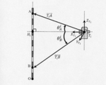
整準されたi番目の角度測量計により、同様に整準された測量ポール上の計測点A、Bと角度測量計の相対位置・姿勢は、図12にしたがって次のように求まる。ここで、点O、A、Bはポール上の計測点(高位、低位)であり、点Oをグローバル座標系の原点(ポールと地面との交点)とする。点Tiはi番目の角度測量計のローカル座標系の原点、点Hiはポール上におけるTiからの垂線の足で、軸XTi、YTi、XTiは角度測量計のローカル座標系の各軸を指す。また、角度θi Aは角度
 角度θi
Bは角度
角度θi
Bは角度
 とする。各線分は次のようになる。
 したがって、ベクトル
 は、以下のようになる。
 レーザ距離計により線分TiA、TiB の実測値がある場合には、その値も考慮して最適化によりベクトル
 求める。
求める。
[C-1]測量機による直接計測
1) 角度測量による測量ポール上の計測点の相対位置・姿勢の定義:
整準されたi番目の角度測量計により、同様に整準された測量ポール上の計測点A、Bと角度測量計の相対位置・姿勢は、図12にしたがって次のように求まる。ここで、点O、A、Bはポール上の計測点(高位、低位)であり、点Oをグローバル座標系の原点(ポールと地面との交点)とする。点Tiはi番目の角度測量計のローカル座標系の原点、点Hiはポール上におけるTiからの垂線の足で、軸XTi、YTi、XTiは角度測量計のローカル座標系の各軸を指す。また、角度θi Aは角度
[C-2]グローバル座標系における角度測量計の位置・姿勢
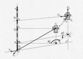
ベースとなる角度測量計T0とし、角度測量計T0のローカル座標系の姿勢をグローバル座標系の姿勢、測量ポール上の原点Oをグローバル座標系の原点とする。このとき、前節で得られたベクトル
 を用いて、グローバル座標系に対する角度測量計T0のローカル座標系の同次変換行列O
0Hを図13にしたがい次のように定義できる。
を用いて、グローバル座標系に対する角度測量計T0のローカル座標系の同次変換行列O
0Hを図13にしたがい次のように定義できる。
 また、グローバル座標系における他の角度測量計の位置・姿勢についても、次のように定める。
 ここで、角度θ0
Tiは角度
ここで、角度θ0
Tiは角度
 角度θi
T0は角度
角度θi
T0は角度
 とする。
とする。
ベースとなる角度測量計T0とし、角度測量計T0のローカル座標系の姿勢をグローバル座標系の姿勢、測量ポール上の原点Oをグローバル座標系の原点とする。このとき、前節で得られたベクトル
セオドライトをカメラのマウンタとするとき、その位置・姿勢を表す外部パラメータ行列iBmは、次のように定義できる。

[C-3]測量マーカ付きカメラマウンタの位置・姿勢
図14において、測量マーカ付きカメラマウンタのローカル座標系の原点をFiとする。この座標系の、グローバル座標系に対する位置OpFiと姿勢O FiR を最適化により次のように求める。
 ここで、OpiPj は各測量マーカの点(j=1,…,4)である。
wfrillはマーカ間距離の設計値、iLslopej、iLhorizontalj、iLverticaljは、レーザ距離計で測ったマーカへの斜距離・水平距離・高低差である。また、角度iθhorizontalj、iθverticaljは、角度距離計で測ったマーカへの方向角・高度角を指す。測量マーカ付きカメラマウンタトをカメラのマウンタとするとき、前節と同様に外部バラメータiBmは次のように定義される。

図14において、測量マーカ付きカメラマウンタのローカル座標系の原点をFiとする。この座標系の、グローバル座標系に対する位置OpFiと姿勢O FiR を最適化により次のように求める。
wfrillはマーカ間距離の設計値、iLslopej、iLhorizontalj、iLverticaljは、レーザ距離計で測ったマーカへの斜距離・水平距離・高低差である。また、角度iθhorizontalj、iθverticaljは、角度距離計で測ったマーカへの方向角・高度角を指す。測量マーカ付きカメラマウンタトをカメラのマウンタとするとき、前節と同様に外部バラメータiBmは次のように定義される。
[C-4]相対外部パラメータの定義と最適化:
カメラの外部パラメータ行列iBに対して、カメラマウンタの外部パラメータ行列iBmのみが測量機で直接計測をすることができる。それらは相対外部パラメ―タ行列
 を用いて次のように変換できる。
 相対外部パラメ―タ行列を第2手法で最適化すると、次の問題になる。

カメラの外部パラメータ行列iBに対して、カメラマウンタの外部パラメータ行列iBmのみが測量機で直接計測をすることができる。それらは相対外部パラメ―タ行列
現場での計測だけではなく、相対外部パラメータ行列だけを求めるための事前のキャリブレーションを行えるのであれば、カメラの焦点距離とカメラ-マウンタ間の相対外部パラメータ行列を最適化によって求めるのが好ましい。焦点距離を事前に求めて固定する方が、現場で妥当なカメラ位置を求めることができる。このとき、カメラマウンタとして角度測量計を用いるならば、より厳密にカメラの焦点距離を求めることができる。具体的にその手順について述べる。まず、整準された測量ポールに対して、整準された角度測量計を用いて、前述のようにグローバル座標系を定義する。次に、一定間隔(1°ずつ、±10°の範囲)で動かし、測量ポールを撮影する。そのことで、測量ポール上にコントロールポイントを定義することができる(図15参照)。セオドライトの精度に保証されたコントロールポイントの位置を得ることができる。
[D]測量機をカメラマウンタに用いたカメラシステムにおけるカメラキャリブレーション
測量機をカメラマウンタに用いた実施形態におけるキャリブレーションについて詳細に説明する。カメラシステムは、複数個(例えば、4個ないし2個)のカメラからなるカメラユニットを備え、各カメラユニットは測量機(セオドライトないしトータルステーション)に搭載されている。各カメラユニットは、測量機の可動部に搭載されており、測角時に可動部と一体で水平方向及び縦方向に回動可能となっている。1つの態様では、1つのカメラユニットがトータルステーションに搭載されており、他のカメラユニットがセオドライトに搭載されている。もちろん、複数のカメラユニットが複数のトータルステーションに搭載されていてもよい。本セクションの説明において、iはセオドライトの通し番号を示し、jはi番目のセオドライトに搭載されたj番目のカメラを示す。上記セクション[C]では、iはカメラの通し番号を示し、カメラのマウンタ(セオドライトである場合も含む)には、カメラの通し番号が割り当てある点に留意されたい。
測量機をカメラマウンタに用いた実施形態におけるキャリブレーションについて詳細に説明する。カメラシステムは、複数個(例えば、4個ないし2個)のカメラからなるカメラユニットを備え、各カメラユニットは測量機(セオドライトないしトータルステーション)に搭載されている。各カメラユニットは、測量機の可動部に搭載されており、測角時に可動部と一体で水平方向及び縦方向に回動可能となっている。1つの態様では、1つのカメラユニットがトータルステーションに搭載されており、他のカメラユニットがセオドライトに搭載されている。もちろん、複数のカメラユニットが複数のトータルステーションに搭載されていてもよい。本セクションの説明において、iはセオドライトの通し番号を示し、jはi番目のセオドライトに搭載されたj番目のカメラを示す。上記セクション[C]では、iはカメラの通し番号を示し、カメラのマウンタ(セオドライトである場合も含む)には、カメラの通し番号が割り当てある点に留意されたい。
[D-1]ワールド座標系におけるセオドライト座標系
ワールド座標系からのセオドライト座標系への同次変換行列の取得について説明する。先ず、セオドライト及びトータルステーションを三脚に搭載する。各三脚を、各カメラの視野に計測範囲が含まれるように立てる。セオドライト及びトータルステーションを、水準器を用いて整準する。計測範囲の中心に測量用ポールを立てる。測量用ポールは、測量で一般に用いられる周知のポールであり、例えば、赤と白のストライプが10cm幅で形成されている。ポール上の上側の計測点をA、下側の計測点をBとする。
ワールド座標系からのセオドライト座標系への同次変換行列の取得について説明する。先ず、セオドライト及びトータルステーションを三脚に搭載する。各三脚を、各カメラの視野に計測範囲が含まれるように立てる。セオドライト及びトータルステーションを、水準器を用いて整準する。計測範囲の中心に測量用ポールを立てる。測量用ポールは、測量で一般に用いられる周知のポールであり、例えば、赤と白のストライプが10cm幅で形成されている。ポール上の上側の計測点をA、下側の計測点をBとする。
各セオドライトないし各トータルステーションにおいて、ポール上の計測点Aを視準し、YawA及びPitchAを読む。Yawをロックして計測点Bを視準し、PitchBを読む。YawAをセオドライトやトータルステーションの初期Yaw角度として設定する。すなわち、YawAでYawをリセットする。
各セオドライトないし各トータルステーションにおいて、以下のように座標系を設定する。各セオドライトないし各トータルステーションの中心を原点とし、z軸を、Yaw=YawA及びPitch=0(水平)にとり、x軸をPitch=90°の方向(垂直)にとる。
トータルステーションの座標系を座標系{0}とする。セオドライトの座標系を基準に反時計回りに座標系{1},{2},..,{M}とする。ここで、Mはセオドライトの番号である。M=3である。
ポールの計測点Bにおいて、グローバル座標{a}を設定する。z軸とx軸はトータルステーションの座標系{0}のz軸とx軸に一致させる。
カメラマウンタ(例えば、1つのトータルステーションと複数のセオドライト)間のYaw角度をセオドライトないし各トータルステーションを用いて計測する。例えば、座標系{0}から座標系{1}のYaw角度をα01によって表す。この測定においては、ターゲットとなるセオドライトないしトータルステーションの振り子錘の先端をターゲット(特徴点)とする。複数のカメラマウンタ間のYaw角度を計測することで、角度αij(i=0,…,M;J=0,…M;i≠j)を取得する。
計測点Aと計測点Bの距離が既知であることを用いて、三角法によってワールド座標系からのセオドライト座標系への同次変換行列
 を取得する
を取得する
[D-2]カメラの内部パラメータ
カメラの内部パラメータの取得について説明する。各カメラユニットは、セオドライトないしトータルステーションのYaw回転と一体で回転可能な水平面上の固定された4つのカメラを備えている。カメラは、セクター角度22.5°で扇形状に軸
 でセットされており、軸はz-x平面に対して対称である。各軸を軸
 回りに9.65°で回転させる。
カメラの内部パラメータの取得について説明する。各カメラユニットは、セオドライトないしトータルステーションのYaw回転と一体で回転可能な水平面上の固定された4つのカメラを備えている。カメラは、セクター角度22.5°で扇形状に軸
カメラは、各トータルステーション及びセオドライトをi=0,…,Mとし、各トータルステーション及びセオドライト上の各カメラをYaw軸時計回りにj=0,1,2,3として、カメラ(i,j)のようにインデックスされる。
カメラはしぼり開放とし、∞にフォーカスする。光量はシャッタースピードでコントロールする。チェッカーボードを15の異なる位置及び向きでカメラに見せる。OpenCVのcvCalibrateCamera2を用いて、カメラの内部パラメータPij(i=1,…,M;J=1,2,3,4)を取得する。
カメラ座標系における3次元位置
 は、カメラ画像Iijにおいて、以下の形式で現れる。
 歪みフリー画像Iij
*は、Pijを用いてIijから以下のような形式で生成され、
歪みフリー画像Iij
*は、Pijを用いてIijから以下のような形式で生成され、
 歪みフリー画像は、カメラ座標系の3次元位置
 を
を
 で示す。
で示す。
[D-3]セオドライト/トータルステーション座標系におけるカメラ座標系
セオドライト座標系からのカメラ座標系への同次変換行列の取得について説明する。水準器を用いてポールを垂直に立てる。セオドライト/トータルステーション(i=0,…,M)について、座標系{i}のセオドライトないしトータルステーションを、水準器を用いて垂直に立てる。カメラの高さを水平面から例えば1.7mとし、ポールからカメラまでの距離を例えば10mとする。セオドライト/トータルステーションのpitch角度を0°(水平)に設定する。そして、Yawを調整してポールの中心を視準し、Yaw角度(0°)をリセットする。
セオドライト座標系からのカメラ座標系への同次変換行列の取得について説明する。水準器を用いてポールを垂直に立てる。セオドライト/トータルステーション(i=0,…,M)について、座標系{i}のセオドライトないしトータルステーションを、水準器を用いて垂直に立てる。カメラの高さを水平面から例えば1.7mとし、ポールからカメラまでの距離を例えば10mとする。セオドライト/トータルステーションのpitch角度を0°(水平)に設定する。そして、Yawを調整してポールの中心を視準し、Yaw角度(0°)をリセットする。
ポールの軸上に2つの点A、Bを決定し、点A、Bの3次元位置を
 として三角法で計算する。セオドライトないしトータルステーションの回転角度を、β0=-33.75°、β1=-11.25°、β2=11.25°、β3=33.75°、に設定する。カメラ(j=0,…,M)、及び、角度(k=0,…,20)について、座標系{i}のYawをγjkに設定し、ここで、
 である。そして、角度(k=0,…,20)を変化させて、カメラ(i,j)の画像Iijkを取得する。
 上記2つの式を満たすように最適化計算を行って、セオドライト座標系からのカメラ座標系への同次変換行列
 を取得する。同様に、次のカメラjについて同時変換行列を取得し、次のセオドライトについて同様に計算を行って同時変換行列を取得する。
本実施形態に係るキャリブレーションの結果は以下の3つの式で表される。

[E]モーションキャプチャシステム
図16を参照しつつ、本実施形態に係るモーションキャプチャシステムについて説明する。モーションキャプチャシステムは、いわゆるビデオモーションキャプチャシステム(非特許文献1参照)であり、モーションキャプチャ・カメラシステムで取得された複数のカメラの映像から深層学習を用いて推定した関節位置から3次元再構成を行うものであり、対象は、いかなるマーカやセンサを装着する必要がなく、計測空間も限定されない。複数台のRGBカメラの映像から完全非拘束でモーションキャプチャを行うもので、屋内の居住空間から、屋外でのスポーツフィールドの広い空間まで、原理的には映像が取得できれば、動作計測が可能となる技術である。以下に述べるモーションキャプチャシステムは、例示であり、本発明に係るモーションキャプチャ・カメラシステムと共に用いるモーションキャプチャを限定するものではなく、他の手法を採用してもよい。
図16を参照しつつ、本実施形態に係るモーションキャプチャシステムについて説明する。モーションキャプチャシステムは、いわゆるビデオモーションキャプチャシステム(非特許文献1参照)であり、モーションキャプチャ・カメラシステムで取得された複数のカメラの映像から深層学習を用いて推定した関節位置から3次元再構成を行うものであり、対象は、いかなるマーカやセンサを装着する必要がなく、計測空間も限定されない。複数台のRGBカメラの映像から完全非拘束でモーションキャプチャを行うもので、屋内の居住空間から、屋外でのスポーツフィールドの広い空間まで、原理的には映像が取得できれば、動作計測が可能となる技術である。以下に述べるモーションキャプチャシステムは、例示であり、本発明に係るモーションキャプチャ・カメラシステムと共に用いるモーションキャプチャを限定するものではなく、他の手法を採用してもよい。
1枚の画像に含まれる対象の数は限定されない。例えば、競技スポーツでは、カメラによって複数人の人間の動作を撮影することで、各画像には、複数の人間が含まれることになる。各画像において、前記複数の人間から選択された1人あるいは任意数の複数の人間の関節位置を取得する。1枚の画像に複数人が含まれている場合に、例えば、PAFとPCM(Zhe Cao, Tomas Simon, Shih-En Wei, and Yaser Sheikh. Realtime multi-person 2d pose estimation using part affinity fields. In Proceedings IEEE Conference on Computer Vision and Pattern Recognition. CVPR 2017, 2017.)を用いれば、各人毎に関節位置を同時に取得することができる。また、計測初期時に各人毎に関節位置を識別すれば、その後はフレーム間の連続性で関節位置を追跡することで、各人を識別することができる。モーションキャプチャシステムによる動作取得において、対象はリンク構造ないし多関節構造を備えている。典型的には対象は骨格構造を備えた人間であるが、対象はロボットであってもよい。
ビデオモーションキャプチャシステムは、対象の動作を取得するモーションキャプチャ・カメラシステムと、カメラシステムで取得された画像に基づいて、関節位置を含む特徴点(Keypoints)の位置の確からしさの程度を色強度で表示するヒートマップ情報を取得するヒートマップ取得部と、ヒートマップ取得部で取得されたヒートマップ情報を用いて対象の関節位置を取得する関節位置取得部と、関節位置取得部で取得された関節位置を平滑化する平滑化処理部と、対象の身体の骨格構造、ビデオシステムで取得された画像の時系列データ、関節位置取得部で取得された関節位置の時系列データ等を記憶する記憶部と、カメラシステムで取得された対象の画像や対象のポーズに対応する骨格構造等を表示するディスプレイと、を備えている。
モーションキャプチャ・カメラシステムは複数のカメラを備え、複数の同期したカメラによって対象者の動作が撮影され、各カメラから所定のフレームレートでRGB画像が出力される。同時刻で取得された複数枚のカメラ画像がヒートマップ取得部に送信される。ヒートマップ取得部は、RGB画像に基づいてヒートマップを生成する。ヒートマップは、身体上の特徴点の位置の確からしさの尤度の空間分布を表す。ヒートマップ取得部は、入力画像に基づいて、各関節位置を含む身体上の特徴点(keypoints)の位置の確からしさの尤度の2次元あるいは3次元の空間分布を生成し、前記尤度の空間分布をヒートマップ形式で表示する。ヒートマップ取得部は、典型的には、畳み込みニューラルネットワーク(CNN)を用いて、入力された単一の画像から対象の身体上の特徴点の位置(典型的には関節位置)を、ヒートマップとして推定する。
生成されたヒートマップ情報は関節位置取得部に送信され、関節位置取得部によって関節位置が取得される。関節位置取得部は、ヒートマップ取得部から取得されたヒートマップ情報を用いて関節位置候補を推定し、当該関節位置候補を用いて逆運動学に基づく最適化計算を実行することで骨格モデルの関節角、関節位置を更新する。関節位置取得部は、ヒートマップデータに基づいて関節位置候補を推定する関節位置候補取得部と、関節位置候補を用いて逆運動学に基づく最適化計算を実行して関節角を算出する逆運動学計算部と、算出された関節角を用いて順運動学計算を実行して関節位置を算出する順運動学計算部と、を備えている。取得された関節位置データは、関節位置の時系列データとして記憶部に格納される。
取得された関節位置データは、平滑化処理部に送信され、平滑化関節位置、関節角が取得される。平滑化処理部の平滑化関節位置取得部では、取得された関節位置に対して、過去のフレームにおける関節位置を用いて、平滑化処理を実行することで、関節位置の時間的な動きを滑らかにする。平滑化された特徴点の位置を用いて再度逆運動学に基づく最適化計算を実行して、対象の関節角を取得し、取得した関節角を用いて順運動学計算を実行して、対象の関節位置を取得する。平滑化された関節位置ないし関節角、及び、対象の身体の骨格構造によって対象のポーズが決定され、ポーズの時系列データからなる対象の動作をディスプレイに表示する。
図17にモーションキャプチャを用いた動作解析の処理工程を例示する。本実施形態に係るモーションキャプチャにより対象の動作を取得する。取得した関節角及び関節位置の時系列データを取得する。さらにこれに基づいて、逆動力学計算により関節トルクを取得し、前記関節トルクを用いて、筋を模倣したワイヤーを備えた筋骨格モデルにおけるワイヤー張力を最適化計算(2次計画法や線形計画法)により取得し、前記ワイヤー張力を用いて筋活動度を算出し、筋活動度の程度に応じた色が割り当てられた筋骨格画像を生成し、視覚化された筋活動度を伴う筋骨格画像を所定のフレームレートで出力して動画としてディスプレイに表示する。このように、対象の運動の撮影から、運動時の対象の3次元ポーズの取得、運動に必要な筋活動の推定と可視化までを、自動的に効率的に行うことができる。
Claims (32)
- 1つあるいは複数のカメラからなる複数のカメラユニットと、
各カメラユニットが搭載される複数のカメラマウンタと、
各カメラ画像を3次元再構成するためのカメラパラメータを取得するキャリブレーション手段と、
測角機能を備えた1つあるいは複数の測量機と、
を備えたモーションキャプチャ・カメラシステムであって、
前記カメラパラメータは、グローバル座標系における各カメラの位置・姿勢を表す外部パラメータを含み、
前記キャリブレーション手段は、グローバル座標系における各カメラマウンタの位置及び姿勢を用いて前記外部パラメータを取得するものであり、前記グローバル座標系におけるカメラマウンタの位置及び姿勢は、前記1つあるいは複数の測量機を用いて取得される、
モーションキャプチャ・カメラシステム。 - 前記1つあるいは複数の測量機のうちの1つあるいは複数の測量機は、測距機能を備えている、請求項1のモーションキャプチャ・カメラシステム。
- 前記複数のカメラマウンタの一部あるいは全部は、前記測量機である、請求項1、2いずれか1項に記載のモーションキャプチャ・カメラシステム。
- 前記複数のカメラマウンタの一部あるいは全部は、前記測量機によって測量可能な複数のマーカを備えている、請求項1、2いずれか1項に記載のモーションキャプチャ・カメラシステム。
- 前記カメラマウンタは、3つ以上のマーカを備えた平面を有している、請求項4に記載のモーションキャプチャ・カメラシステム。
- 前記キャリブレーション手段は、各カメラの撮像空間に位置する複数の特徴点のグローバル座標系での位置情報と、各カメラ画像での各特徴点の位置情報と、を用いるものであり、
前記複数の特徴点のグローバル座標系での位置情報は、前記測量機を用いて取得される、
請求項1~5いずれか1項に記載のモーションキャプチャ・カメラシステム。 - 前記キャリブレーション手段は、各カメラマウンタ座標系における当該カメラマウンタに搭載された各カメラの位置・姿勢を用いる、
請求項1~6いずれか1項に記載のモーションキャプチャ・カメラシステム。 - 前記キャリブレーション手段は、各カメラマウンタ座標系における当該カメラマウンタに搭載された各カメラの位置・姿勢を取得する手段を備える、
請求項7に記載のモーションキャプチャ・カメラシステム。 - 前記カメラマウンタは前記測量機から構成されており、
前記カメラマウンタ座標系における前記カメラの位置及び姿勢は、前記測量機を用いて取得される、
請求項8に記載のモーションキャプチャ・カメラシステム。 - 前記キャリブレーション手段は、最適化計算によって前記外部パラメータを取得する、請求項1~9いずれか1項に記載のモーションキャプチャ・カメラシステム。
- 前記最適化計算において、グローバル座標系の位置情報が未知の1つあるいは複数の特徴点に対応する各カメラ画像の位置情報が用いられる、
請求項10に記載のモーションキャプチャ・カメラシステム - 前記カメラパラメータは、光学パラメータと内部パラメータを含み、前記キャリブレーション手段は、最適化計算によって前記外部パラメータ及び前記光学パラメータと前記内部パラメータを取得する、請求項10、11いずれか1項に記載のモーションキャプチャ・カメラシステム。
- 1つあるいは複数のカメラからなる複数のカメラユニットと、
各カメラユニットが搭載される複数のカメラマウンタと、
を備えたモーションキャプチャ・カメラシステムにおいて、前記複数のカメラ画像を3次元再構成するためのカメラパラメータを取得するキャリブレーション方法であって、
前記カメラパラメータは、グローバル座標系における各カメラの位置・姿勢を表す外部パラメータを含み、
測角機能を備えた1つあるいは複数の測量機を用いて、グローバル座標系における各カメラマウンタの位置及び姿勢を取得すること、
グローバル座標系における各カメラマウンタの位置及び姿勢を用いて前記外部パラメータを取得すること、
を含むキャリブレーション方法。 - 前記1つあるいは複数の測量機のうちの1つあるいは複数の測量機は、測距機能を備えている、請求項13に記載のモーションキャプチャ・カメラシステム。
- 前記複数のカメラマウンタの一部あるいは全部は、前記測量機であり、複数の測定点の測量データを用いてグローバル座標系における各カメラマウンタの位置及び姿勢を取得する、請求項13、14いずれか1項に記載のキャリブレーション方法。
- 前記複数のカメラマウンタの一部あるいは全部は、前記測量機によって測量可能な複数のマーカを備えており、複数のマーカの測量データを用いてグローバル座標系における当該カメラマウンタの位置及び姿勢を取得する、請求項13、14いずれか1項に記載のキャリブレーション方法。
- 前記カメラマウンタは、3つ以上のマーカを備えた平面を有している、請求項16に記載のキャリブレーション方法。
- 前記外部パラメータの取得において、各カメラの撮像空間に位置する複数の複数の特徴点のグローバル座標系での位置情報と、各カメラ画像での各特徴点の位置情報と、が用いられ、
前記複数の特徴点のグローバル座標系での位置情報は、前記測量機を用いて取得される、
請求項13~17いずれか1項に記載のキャリブレーション方法。 - 前記外部パラメータの取得において、各カメラマウンタ座標系における当該カメラマウンタに搭載された各カメラの位置・姿勢を用いる、
請求項13~18いずれか1項に記載のキャリブレーション方法。 - 各カメラマウンタ座標系における当該カメラマウンタに搭載された各カメラの位置・姿勢を取得することを含む、
請求項19に記載のキャリブレーション方法。 - 前記カメラマウンタは前記測量機から構成されており、
前記カメラマウンタ座標系における前記カメラの位置及び姿勢を、前記測量機を用いて取得する、
請求項20に記載のキャリブレーション方法。 - 最適化計算によって前記外部パラメータを取得する、請求項13~21いずれか1項に記載のキャリブレーション方法。
- 前記最適化計算において、グローバル座標系の位置情報が未知の1つあるいは複数の特徴点に対応する各カメラ画像の位置情報が用いられる、
請求項22に記載のキャリブレーション方法。 - 前記カメラパラメータは、光学パラメータと内部パラメータを含み、最適化計算によって前記外部パラメータ及び前記光学パラメータと前記内部パラメータを取得する、請求項22、23いずれか1項に記載のキャリブレーション方法。
- 1つあるいは複数のカメラからなる複数のカメラユニットと、
各カメラユニットが搭載される複数のカメラマウンタと、
各カメラ画像を3次元再構成するためのカメラパラメータを取得するキャリブレーション手段と、
測角機能を備えた1つあるいは複数の測量機と、
を備えたモーションキャプチャ・カメラシステムであって、
前記キャリブレーション手段は、
前記測量機を用いてグローバル座標系での位置情報が得られている複数の不動特徴点の各カメラ画像での位置情報と、
グローバル座標系の位置情報が未知の1つあるいは複数の特徴点の各カメラ画像での位置情報と、
を用いて、最適化計算によって、前記カメラパラメータを取得する、モーションキャプチャ・カメラシステム。 - 前記不動特徴点は、スポーツフィールドないしコートを形成する要素上の点である、請求項25に記載のモーションキャプチャ・カメラシステム。
- 前記グローバル座標系の位置情報が未知の特徴点は、球技におけるボールである、請求項25、26いずれか1項に記載のモーションキャプチャ・カメラシステム。
- 前記複数のカメラマウンタの一部あるいは全部は、前記測量機である、請求項25~27いずれか1項に記載のモーションキャプチャ・カメラシステム。
- 1つあるいは複数のカメラからなる複数のカメラユニットと、
各カメラユニットが搭載される複数のカメラマウンタと、
を備えたモーションキャプチャ・カメラシステムにおいて、前記複数のカメラ画像を3次元再構成するためのカメラパラメータを取得するキャリブレーション方法は、
モーションキャプチャ前に、測角機能を備えた測量機によって複数の不動特徴点のグローバル座標系での位置情報を取得し、
モーションキャプチャ時に、前記複数の不動特徴点の各カメラ画像での位置情報と、グローバル座標系の位置情報が未知の1つあるいは複数の特徴点の各カメラ画像での位置情報と、を用いて、最適化計算によって、前記カメラパラメータを取得する、キャリブレーション方法。 - 前記不動特徴点は、スポーツフィールドないしコートを形成する要素上の点である、請求項29に記載のキャリブレーション方法。
- 前記グローバル座標系の位置情報が未知の特徴点は、球技におけるボールである、請求項29、30いずれか1項に記載のキャリブレーション方法。
- 前記複数のカメラマウンタの一部あるいは全部は、測角機能を備えた測量機であり、最適化計算において、カメラマウンタの姿勢情報が用いられる、請求項29~31いずれか1項に記載のキャリブレーション方法。
Priority Applications (1)
| Application Number | Priority Date | Filing Date | Title |
|---|---|---|---|
| JP2020557612A JP7395189B2 (ja) | 2018-11-22 | 2019-11-21 | モーションキャプチャ・カメラシステム及びキャリブレーション方法 |
Applications Claiming Priority (2)
| Application Number | Priority Date | Filing Date | Title |
|---|---|---|---|
| US201862770766P | 2018-11-22 | 2018-11-22 | |
| US62/770,766 | 2018-11-22 |
Publications (1)
| Publication Number | Publication Date |
|---|---|
| WO2020105697A1 true WO2020105697A1 (ja) | 2020-05-28 |
Family
ID=70774209
Family Applications (1)
| Application Number | Title | Priority Date | Filing Date |
|---|---|---|---|
| PCT/JP2019/045552 Ceased WO2020105697A1 (ja) | 2018-11-22 | 2019-11-21 | モーションキャプチャ・カメラシステム及びキャリブレーション方法 |
Country Status (2)
| Country | Link |
|---|---|
| JP (1) | JP7395189B2 (ja) |
| WO (1) | WO2020105697A1 (ja) |
Cited By (8)
| Publication number | Priority date | Publication date | Assignee | Title |
|---|---|---|---|---|
| CN113487726A (zh) * | 2021-07-12 | 2021-10-08 | 北京未来天远科技开发有限公司 | 动作捕捉系统和方法 |
| JP2022154076A (ja) * | 2021-03-30 | 2022-10-13 | Kddi株式会社 | 複数カメラ校正装置、方法およびプログラム |
| CN115752391A (zh) * | 2022-09-20 | 2023-03-07 | 北京卫星环境工程研究所 | 一种航天器总装过程中的设备安装精度调测方法 |
| CN115861592A (zh) * | 2023-02-16 | 2023-03-28 | 之江实验室 | 基于神经网络的动作捕捉系统的速度精度优化方法及系统 |
| CN116630431A (zh) * | 2023-04-04 | 2023-08-22 | 中国人民解放军战略支援部队信息工程大学 | 一种大场景下光学运动捕捉系统的精度标定方法 |
| JP2023542469A (ja) * | 2020-09-29 | 2023-10-10 | インターナショナル・ビジネス・マシーンズ・コーポレーション | キーポイント検出に基づくコンピュータによる自動化された相互作用活動認識 |
| KR102769230B1 (ko) * | 2024-09-03 | 2025-02-18 | 주식회사 모빌테크 | 카메라에 대한 파라미터 추정 및 최적화 방법 및 이를 실행하기 위하여 기록매체에 기록된 컴퓨터 프로그램 |
| SE2330358A1 (en) * | 2023-08-18 | 2025-02-19 | Topgolf Sweden Ab | System, calibration apparatus and method for determining a coordinate transformation for two cameras |
Citations (2)
| Publication number | Priority date | Publication date | Assignee | Title |
|---|---|---|---|---|
| JPH11118425A (ja) * | 1997-10-17 | 1999-04-30 | Sony Corp | キャリブレーション方法及び装置、並びにキャリブレーション用データ生成方法 |
| JP2016126425A (ja) * | 2014-12-26 | 2016-07-11 | Kddi株式会社 | 自由視点画像生成装置、方法およびプログラム |
Family Cites Families (4)
| Publication number | Priority date | Publication date | Assignee | Title |
|---|---|---|---|---|
| JP3597832B2 (ja) | 2002-07-19 | 2004-12-08 | ジェイアール西日本コンサルタンツ株式会社 | 軌道狂い計測方法およびその方法に用いられる軌道狂い計測システム |
| JP2004163292A (ja) | 2002-11-13 | 2004-06-10 | Topcon Corp | 測量装置と電子的記憶媒体 |
| JP5366258B2 (ja) | 2010-02-17 | 2013-12-11 | Kddi株式会社 | 大空間カメラ配置における幾何情報に基づく仮想視点画像生成方法およびプログラム |
| EP2383696A1 (en) | 2010-04-30 | 2011-11-02 | LiberoVision AG | Method for estimating a pose of an articulated object model |
-
2019
- 2019-11-21 JP JP2020557612A patent/JP7395189B2/ja active Active
- 2019-11-21 WO PCT/JP2019/045552 patent/WO2020105697A1/ja not_active Ceased
Patent Citations (2)
| Publication number | Priority date | Publication date | Assignee | Title |
|---|---|---|---|---|
| JPH11118425A (ja) * | 1997-10-17 | 1999-04-30 | Sony Corp | キャリブレーション方法及び装置、並びにキャリブレーション用データ生成方法 |
| JP2016126425A (ja) * | 2014-12-26 | 2016-07-11 | Kddi株式会社 | 自由視点画像生成装置、方法およびプログラム |
Non-Patent Citations (1)
| Title |
|---|
| KITAHARA, ITARU ET AL.: "Recording of Multiple Videos in a Large-scale Space for Large-scale Virtualized Reality", THE JOURNAL OF THE INSTITUTE OF IMAGE INFORMATION AND TELEVISION ENGINEERS, vol. 56, no. 8, 1 August 2002 (2002-08-01), pages 120, XP007015542 * |
Cited By (13)
| Publication number | Priority date | Publication date | Assignee | Title |
|---|---|---|---|---|
| JP7643818B2 (ja) | 2020-09-29 | 2025-03-11 | インターナショナル・ビジネス・マシーンズ・コーポレーション | キーポイント検出に基づくコンピュータによる自動化された相互作用活動認識 |
| JP2023542469A (ja) * | 2020-09-29 | 2023-10-10 | インターナショナル・ビジネス・マシーンズ・コーポレーション | キーポイント検出に基づくコンピュータによる自動化された相互作用活動認識 |
| JP7489349B2 (ja) | 2021-03-30 | 2024-05-23 | Kddi株式会社 | 複数カメラ校正装置、方法およびプログラム |
| JP2022154076A (ja) * | 2021-03-30 | 2022-10-13 | Kddi株式会社 | 複数カメラ校正装置、方法およびプログラム |
| CN113487726A (zh) * | 2021-07-12 | 2021-10-08 | 北京未来天远科技开发有限公司 | 动作捕捉系统和方法 |
| CN113487726B (zh) * | 2021-07-12 | 2024-05-14 | 未来元宇数字科技(北京)有限公司 | 动作捕捉系统和方法 |
| CN115752391A (zh) * | 2022-09-20 | 2023-03-07 | 北京卫星环境工程研究所 | 一种航天器总装过程中的设备安装精度调测方法 |
| CN115861592A (zh) * | 2023-02-16 | 2023-03-28 | 之江实验室 | 基于神经网络的动作捕捉系统的速度精度优化方法及系统 |
| CN116630431A (zh) * | 2023-04-04 | 2023-08-22 | 中国人民解放军战略支援部队信息工程大学 | 一种大场景下光学运动捕捉系统的精度标定方法 |
| SE2330358A1 (en) * | 2023-08-18 | 2025-02-19 | Topgolf Sweden Ab | System, calibration apparatus and method for determining a coordinate transformation for two cameras |
| WO2025040597A1 (en) * | 2023-08-18 | 2025-02-27 | Topgolf Sweden Ab | System, calibration apparatus and method for determining a coordinate transformation for two cameras |
| SE546939C2 (en) * | 2023-08-18 | 2025-03-11 | Topgolf Sweden Ab | System, calibration apparatus and method for determining a coordinate transformation for two cameras |
| KR102769230B1 (ko) * | 2024-09-03 | 2025-02-18 | 주식회사 모빌테크 | 카메라에 대한 파라미터 추정 및 최적화 방법 및 이를 실행하기 위하여 기록매체에 기록된 컴퓨터 프로그램 |
Also Published As
| Publication number | Publication date |
|---|---|
| JP7395189B2 (ja) | 2023-12-11 |
| JPWO2020105697A1 (ja) | 2021-10-07 |
Similar Documents
| Publication | Publication Date | Title |
|---|---|---|
| JP7395189B2 (ja) | モーションキャプチャ・カメラシステム及びキャリブレーション方法 | |
| US11645819B2 (en) | Augmented reality system for viewing an event with mode based on crowd sourced images | |
| EP4305600B1 (en) | Registration for augmented reality system for viewing an event | |
| US11527047B2 (en) | Augmented reality system for viewing an event with distributed computing | |
| US20240276056A1 (en) | Augmented reality system for viewing an event with multiple coordinate systems and automatically generated model | |
| JP7427188B2 (ja) | 3dポーズ取得方法及び装置 | |
| US8705799B2 (en) | Tracking an object with multiple asynchronous cameras | |
| US12586305B2 (en) | 3D reference point detection for survey for venue model construction | |
| US6774932B1 (en) | System for enhancing the televised broadcast of a golf game | |
| WO1994029670A1 (en) | Apparatus for measuring position of moving object | |
| WO2020054442A1 (ja) | 関節位置の取得方法及び装置、動作の取得方法及び装置 | |
| CN108961395A (zh) | 一种基于拍照重建三维空间场景的方法 | |
| US20070098250A1 (en) | Man-machine interface based on 3-D positions of the human body | |
| CN113160325A (zh) | 基于进化算法的多摄像机高精度自动标定方法 | |
| US20130016099A1 (en) | Digital Rendering Method for Environmental Simulation | |
| US8223208B2 (en) | Device and method for calibrating an imaging device for generating three dimensional surface models of moving objects | |
| US20150097937A1 (en) | Single-camera motion capture system | |
| US12159359B2 (en) | Use of multiple registrations for augmented reality system for viewing an event | |
| JP2004132831A (ja) | 球体の回転特性と飛行特性の測定方法及び球体の回転特性と飛行特性の測定装置 | |
| Teo | Video-based point cloud generation using multiple action cameras | |
| JP4205004B2 (ja) | キャリブレーション方法 | |
| CN121391919A (zh) | 便携式多目高尔夫实时检测测量方法、设备及电子设备 | |
| Rau et al. | Systematic calibration for a backpacked spherical photogrammetry imaging system | |
| Chong et al. | A photogrammetric application in virtual sport training | |
| KR100874425B1 (ko) | 옥외 광고물 크기 측정 시스템 및 이를 이용한 옥외광고물의 크기 측정방법 |
Legal Events
| Date | Code | Title | Description |
|---|---|---|---|
| 121 | Ep: the epo has been informed by wipo that ep was designated in this application |
Ref document number: 19887575 Country of ref document: EP Kind code of ref document: A1 |
|
| ENP | Entry into the national phase |
Ref document number: 2020557612 Country of ref document: JP Kind code of ref document: A |
|
| NENP | Non-entry into the national phase |
Ref country code: DE |
|
| 122 | Ep: pct application non-entry in european phase |
Ref document number: 19887575 Country of ref document: EP Kind code of ref document: A1 |