WO2020105644A1 - 放電ランプ用カソード部品および放電ランプ - Google Patents
放電ランプ用カソード部品および放電ランプInfo
- Publication number
- WO2020105644A1 WO2020105644A1 PCT/JP2019/045311 JP2019045311W WO2020105644A1 WO 2020105644 A1 WO2020105644 A1 WO 2020105644A1 JP 2019045311 W JP2019045311 W JP 2019045311W WO 2020105644 A1 WO2020105644 A1 WO 2020105644A1
- Authority
- WO
- WIPO (PCT)
- Prior art keywords
- orientation
- degrees
- less
- tungsten
- crystal
- Prior art date
- Legal status (The legal status is an assumption and is not a legal conclusion. Google has not performed a legal analysis and makes no representation as to the accuracy of the status listed.)
- Ceased
Links
Images


Classifications
-
- H—ELECTRICITY
- H01—ELECTRIC ELEMENTS
- H01J—ELECTRIC DISCHARGE TUBES OR DISCHARGE LAMPS
- H01J61/00—Gas-discharge or vapour-discharge lamps
- H01J61/02—Details
- H01J61/04—Electrodes; Screens; Shields
- H01J61/06—Main electrodes
-
- H—ELECTRICITY
- H01—ELECTRIC ELEMENTS
- H01J—ELECTRIC DISCHARGE TUBES OR DISCHARGE LAMPS
- H01J61/00—Gas-discharge or vapour-discharge lamps
- H01J61/02—Details
- H01J61/04—Electrodes; Screens; Shields
- H01J61/06—Main electrodes
- H01J61/067—Main electrodes for low-pressure discharge lamps
-
- H—ELECTRICITY
- H01—ELECTRIC ELEMENTS
- H01J—ELECTRIC DISCHARGE TUBES OR DISCHARGE LAMPS
- H01J61/00—Gas-discharge or vapour-discharge lamps
- H01J61/02—Details
- H01J61/04—Electrodes; Screens; Shields
- H01J61/06—Main electrodes
- H01J61/073—Main electrodes for high-pressure discharge lamps
Definitions
- the embodiment relates to a discharge lamp cathode component and a discharge lamp.
- the -Discharge lamps can be broadly divided into two types: low-pressure discharge lamps and high-pressure discharge lamps.
- the low-pressure discharge lamp includes various arc discharge type discharge lamps such as general lighting, special lighting used for roads and tunnels, paint curing equipment, ultraviolet (UV) curing equipment, sterilization equipment, light cleaning equipment for semiconductors, etc. ..
- High-pressure discharge lamps include water and sewage treatment equipment, general lighting, outdoor lighting such as stadiums, UV curing equipment, exposure equipment such as semiconductors and printed circuit boards, wafer inspection equipment, high-pressure mercury lamps such as projectors, metal halide lamps, and ultra-high pressure. Examples thereof include a mercury lamp, a xenon lamp, and a sodium lamp.
- the discharge lamp is used in various devices such as a lighting device, a video projection device, and a manufacturing device.
- a projection display device using a discharge lamp is known.
- home theaters and digital cinemas have become popular.
- These use a projection type display device called a projector.
- consumption of electrodes of the discharge lamp affects lamp life and flicker of emitted light.
- PWM pulse width modulation
- the cathode part manufactured by using the above technique was applied with a voltage in a state where the cathode part was energized and heated, and the emission current density (mA / mm 2 ) after 10 hours and after 100 hours It is known to have excellent characteristics by measuring the emission current density (mA / mm 2 ) of.
- a conventional cathode part for a discharge lamp exhibits excellent durability for about 100 hours, but the durability deteriorates for a longer time than that.
- the discharge lamp cathode component includes a body portion having a wire diameter of 2 mm or more and 35 mm or less, and a tip portion tapered from the body portion.
- the cathode part includes a tungsten alloy containing 0.5% by mass or more and 3% by mass or less of ThO 2 in terms of ThO 2 , and within 1 mm from the center in the cross section passing through the center of the body and along the length direction of the body.
- FIG. 1 is a side view showing an example of a cathode part for a discharge lamp.
- the discharge lamp cathode component 1 includes a body portion 2 having a wire diameter of 2 mm or more and 35 mm or less, and a tip portion 3 extending from the body portion 2 so as to taper.
- FIG. 1 shows a cathode part 1 for a discharge lamp, a body portion 2, a tip portion 3, a center 4, a line W of the body portion 2, and a length T of the body portion 2.
- FIG. 2 is a view showing an example of a cross section in the length direction of the center 4 of the body portion 2.
- FIG. 1 is a side view showing an example of a cathode part for a discharge lamp.
- the discharge lamp cathode component 1 includes a body portion 2 having a wire diameter of 2 mm or more and 35 mm or less, and a tip portion 3 extending from the body portion 2 so as to taper.
- FIG. 1 shows a catho
- the discharge lamp cathode component may be simply referred to as “cathode component”.
- the body 2 has a columnar shape.
- the wire diameter W is the diameter of the circumferential cross section. When the circumference is an ellipse, the wire diameter W indicates the largest diameter. If the wire diameter W of the body portion 2 is less than 2 mm, the discharge lamp may be insufficient in light emission. If the wire diameter W exceeds 35 mm, the discharge lamp becomes large. Therefore, the wire diameter W is preferably 2 mm or more and 35 mm or less, and more preferably 5 mm or more and 20 mm or less.
- the length T of the body portion 2 is preferably 10 mm or more and 600 mm or less.
- the tip 3 has a shape that tapers from the body 2. Therefore, the region from the point where the taper starts to the end becomes the tip 3.
- the tip 3 has an acute-angled shape in a cross section of the cathode component 1 in the direction a.
- the cathode component 1 is not limited to such a shape, and in the cross section of the cathode component 1 in the direction a, the tip portion 3 may have another shape such as an R shape or a planar shape.
- the tip portion 3 has a tapered shape, it is possible to efficiently discharge between the pair of electrode parts of the discharge lamp.
- the cathode part is made of a tungsten alloy containing 0.5 mass% or more and 3 mass% or less of thorium (also referred to as a thorium component) in terms of oxide (ThO 2 ). If the content is less than 0.5% by mass, the effect of addition is small, and if it exceeds 3% by mass, the sinterability and workability deteriorate. Therefore, the content of thorium is preferably 0.5% by mass or more and 3% by mass or less, further preferably 0.8% by mass or more and 2.5% by mass or less in terms of oxide (ThO 2 ).
- the cathode component 1 is located within 1 mm from the center 4 and has a unit area of 90 ⁇ m ⁇ 90 ⁇ m in a cross section 5 passing through the center 4 of the body 2 and along the length T direction (direction a) of the body 2.
- EBSD electron backscattering diffraction
- the area ratio of the tungsten phase having a crystallographic orientation of -15 degrees or more and 15 degrees or less is the highest in the inverse pole figure (IPF) map in the length direction. high.
- EBSD irradiates a crystal sample with an electron beam.
- the electrons are diffracted and emitted from the sample as reflected electrons.
- the crystal orientation can be measured from the projected pattern.
- X-ray diffraction X-ray diffraction
- EBSD can measure the crystal orientation of individual crystals.
- An analysis method similar to EBSD is sometimes called electron backscattering pattern (EBSP) analysis.
- EBSD analysis is performed by JEOL Co., Ltd. thermal field emission scanning electron microscope (TFE-SEM) JSM-6500F and TSL Solution Co., Ltd. DigiView IV slow scan CCD camera, OIM Data Collection ver. 7.3x, OIM Analysis server. Performed using 8.0.
- TFE-SEM thermal field emission scanning electron microscope
- DigiView IV slow scan CCD camera OIM Data Collection ver. 7.3x
- OIM Analysis server Performed using 8.0.
- the measurement conditions of the EBSD analysis are as follows: electron beam acceleration voltage 20 kV, irradiation current 12 nA, sample tilt angle 70 degrees, measurement area unit area 90 ⁇ m ⁇ 90 ⁇ m, measurement position within 1 mm from center 4, measurement interval 0.3 ⁇ m / step. including.
- the cross section 5 is the measurement surface, and the cross section 5 is irradiated with an electron beam to obtain a diffraction pattern.
- the measurement surface of the measurement sample is polished until the surface roughness Ra becomes 0.8 ⁇ m or less.
- the measurement point is the cross section 5 in the length T direction (direction a) that passes through the center 4 of the body 2.
- the center 4 of the body portion 2 is a point where a straight line passing through the midpoint of the line W of the body portion 2 and a straight line passing through the midpoint of the length T intersect.
- the cross section 5 is a cross section that passes through the center 4 and is horizontal in the length T direction (direction a).
- the crystal orientation indicates the direction using the basic vector.
- the notation consisting of a combination of square brackets ([]) and the numbers between the square brackets indicates only a specific crystal orientation.
- a notation consisting of a combination of angle brackets ( ⁇ >) and a number sandwiched between angle brackets indicates a specific crystal orientation and an equivalent direction.
- the ⁇ 101> direction indicates that the direction equivalent to [101] is included.
- the fact that the preferential orientation of the tungsten phase in the direction a is the ⁇ 101> orientation means that the ⁇ 101> orientation has the highest proportion of all the crystal orientations.
- the IPF map is a crystal orientation map.
- the ratio of the area deviated from the predetermined crystal orientation can be obtained by the area ratio.
- the IPF map can be obtained according to the above-mentioned EBSD measurement method. By color mapping, the area ratio can be easily obtained by image analysis.
- the preferred orientation of the tungsten phase is ⁇ 101> orientation.
- Abnormal grain growth is the coarsening of tungsten crystals during the manufacturing process or use of the discharge lamp.
- Thorium is an emitter material. Thorium is distributed at grain boundaries between tungsten crystals. When the tungsten crystal grows abnormally, the distribution state of thorium changes. This reduces the flicker life and the illuminance maintenance rate. The flicker life is the time until the flicker phenomenon occurs.
- the cathode part for a discharge lamp of the embodiment suppresses abnormal grain growth of tungsten crystals.
- Abnormal grain growth occurs not only during the manufacturing process of the cathode component but also during use of the discharge lamp.
- Coarse grains are formed during use of the discharge lamp after incorporation of the cathode component, even though the cathode component prior to incorporation into the discharge lamp does not have the coarse grains formed by abnormal grain growth.
- the area ratio of the tungsten phase having a crystal orientation with an orientation difference of ⁇ 15 degrees or more and 15 degrees or less with respect to the orientation is preferably 50% or more.
- the same effect as the ⁇ 101> orientation can be obtained.
- the area ratio of the tungsten phase having a crystal orientation with an orientation difference of less than ⁇ 15 degrees with respect to the ⁇ 101> orientation is less than 50%, the effect of improving the characteristics may be insufficient. Further, the effect of suppressing abnormal grain growth can be enhanced by controlling the area ratio of the tungsten phase in a minute region having a unit area of 90 ⁇ m ⁇ 90 ⁇ m. This can prolong the flicker life.
- the orientation difference with respect to the ⁇ 101> orientation deviates from the range of ⁇ 15 degrees, the proportion of the tungsten phase having a crystal orientation other than the desired crystal orientation increases.
- the upper limit of the area ratio is preferably 80% or less. If it exceeds 80%, it may be difficult to control the crystal orientation in the direction b perpendicular to the cross section 5.
- the area ratio of the tungsten phase having a crystal orientation with an orientation difference of ⁇ 10 degrees or more and 10 degrees or less with respect to the ⁇ 101> orientation is 35% or more, and further 50% or more. preferable.
- the area ratio of the tungsten phase having a crystal orientation having an orientation difference within ⁇ 10 degrees with respect to the ⁇ 101> orientation is 35% or more, which means that the area ratio of the tungsten phase having a crystal orientation close to the ⁇ 101> orientation is high. Indicates that.
- the area ratio is preferably 65% or less. Thereby, abnormal grain growth can be further suppressed.
- the area ratio of the tungsten phase having a crystal orientation with an orientation difference of ⁇ 5 degrees or more and 5 degrees or less with respect to the ⁇ 101> orientation is preferably 10% or more, and more preferably 15% or more.
- the area ratio is preferably 30% or less.
- the area ratio of the tungsten phase having a crystal orientation within ⁇ 15 degrees, ⁇ 10 degrees, and ⁇ 5 degrees with respect to the ⁇ 101> orientation satisfies the respective ranges.
- the area ratios are preferably larger in the order of “ ⁇ 5 degrees or less” ⁇ “ ⁇ 10 degrees or less” ⁇ “ ⁇ 15 degrees or less”.
- the EBSD analysis is performed on a region that passes through the center 4 of the body portion 2 and is located within 1 mm from the center in the cross-section 5 in the length T direction (direction a) and has a unit area of 90 ⁇ m ⁇ 90 ⁇ m, it is perpendicular to the cross-section 5.
- the area ratio of the tungsten phase having a crystal orientation with an orientation difference of ⁇ 15 degrees or more and 15 degrees or less with respect to the ⁇ 111> orientation is 15% or more and 50% or less.
- the same effect as the ⁇ 111> orientation can be obtained. Even if the crystal orientation is within ⁇ 15 degrees with respect to the ⁇ 111> orientation, if the area ratio is less than 15% or more than 50%, the effect of improving the characteristics may be insufficient. Therefore, the area ratio is preferably 15% or more and 50% or less, and more preferably 18% or more and 40% or less.
- the effect of suppressing abnormal grain growth can be enhanced by controlling the area ratio of the tungsten phase having a predetermined crystal orientation in a minute region having a unit area of 90 ⁇ m ⁇ 90 ⁇ m. This can prolong the flicker life.
- the area ratio of the tungsten phase having a crystal orientation with an orientation difference of ⁇ 10 degrees or more and 10 degrees or less with respect to the ⁇ 111> orientation is 5% or more and 30% or less. Further, it is preferably within the range of 10% or more and 25% or less.
- the area ratio of the tungsten phase having a crystal orientation with an orientation difference of ⁇ 5 degrees or more and 5 degrees or less with respect to the ⁇ 111> orientation is 1% or more and 15% or less. Further, it is preferably 3% or more and 10% or less.
- the area ratios of the tungsten phases having crystal orientations within ⁇ 15 degrees, ⁇ 10 degrees, and ⁇ 5 degrees with respect to the ⁇ 111> orientation satisfy the above ranges. It is preferable that the respective area ratios are large in the order of "within ⁇ 5 degrees" ⁇ "within ⁇ 10 degrees” ⁇ "within ⁇ 15 degrees".
- the larger order means that there is a tungsten phase having a crystallographic orientation having an orientation difference within ⁇ 5 degrees, ⁇ 6 degrees to ⁇ 10 degrees, and ⁇ 11 degrees to ⁇ 15 degrees. ..
- the occurrence of abnormal grain growth can be suppressed by controlling the area ratio of each.
- the direction b in FIG. 2 is a direction perpendicular to the cross section 5 in the length T direction (direction a).
- a cross section 5 in the length T direction (direction a) is a measurement cross section of the crystal orientation difference.
- the crystal orientation most strongly oriented in the length T direction (direction a) is the ⁇ 101> orientation.
- the grain growth can be further suppressed by allowing the tungsten phase having a crystal orientation close to the ⁇ 111> orientation to exist in the vertical direction b of the cross section 5 at a predetermined ratio.
- the control of the crystal orientation and its area ratio differs depending on the direction. Thereby, grain growth can be suppressed and the life of the cathode component can be extended.
- the crystal orientation By controlling the crystal orientation in this manner, for example, elongated crystal grains can be formed. By forming elongated crystal grains, grain growth can be suppressed.
- the average aspect ratio of crystal grains is 2 or more.
- the longest diagonal line of the crystal shown in the image observed with the laser microscope or the SEM is the major axis.
- the length extended vertically from the center of the major axis is defined as the minor axis.
- (Major axis + minor axis) / 2 particle size. This operation is performed for 10 or more grains, and the average value is defined as the average grain size.
- Major axis / minor axis aspect ratio.
- the average value of 10 or more grains is defined as the average aspect ratio.
- the crystal with all the contours is measured.
- the average grain size of the tungsten crystal is preferably 20 ⁇ m or less. When the average particle size exceeds 20 ⁇ m, it becomes difficult to control the orientation ratio (area ratio) in a region having a unit area of 90 ⁇ m ⁇ 90 ⁇ m. If the average particle size is large, the durability is likely to decrease due to the particle growth. Thorium is distributed at grain boundaries between tungsten crystals. By setting the average grain size of the tungsten crystal to 20 ⁇ m or less, the distribution state of the emitter material can be made uniform. This can improve the discharge characteristics.
- the average grain size of the tungsten crystal is obtained using the crystal grain map when performing EBSD analysis.
- the crystal grain map of the tungsten crystal is the same crystal grain when the measurement points of the tungsten phase having the crystal orientations with the crystal orientation difference within ⁇ 5 degrees in the area of the unit area 90 ⁇ m ⁇ 90 ⁇ m exist continuously. Identified and displayed as.
- the average particle size is calculated from the area of the identified crystal particles in a region having a unit area of 90 ⁇ m ⁇ 90 ⁇ m.
- the particle size is equivalent to a circle.
- the boundary of the region having a unit area of 90 ⁇ m ⁇ 90 ⁇ m is calculated as a crystal grain boundary.
- the average particle diameter is the median diameter (average particle diameter D 50 ). That is, it is the cumulative particle size.
- the average grain size D 50 of the tungsten crystal is preferably 20 ⁇ m or less, more preferably 15 ⁇ m or less.
- the cross-section 5 is the measurement point of the average grain size D 50 of the tungsten crystal. It is preferable that the average grain diameter D 50 of the tungsten crystal is 20 ⁇ m or less regardless of where the cross section 5 and the cross section in the wire diameter W direction (direction b) are measured.
- the particle size D 90 when the cumulative frequency ratio from the small diameter side in the particle size distribution of the tungsten crystal is 90% is preferably 25 ⁇ m or less.
- the method of determining the particle size D 90 is the same as the average particle size D 50 . It is preferable that D 90 ⁇ D 50 ⁇ 7 ⁇ m. The fact that the difference between the particle size D 90 and the average particle size D 50 is 7 ⁇ m or less indicates that there is no variation in particle size and there are no coarse particles.
- the lower limit of the average particle diameter D 50 of the tungsten crystal is not particularly limited, but it is preferably 3 ⁇ m or more. When the average particle size D 50 is smaller than 3 ⁇ m, it becomes difficult to control the difference from the particle size D 90 to 7 ⁇ m or less.
- the grain size D 90 is also measured using the crystal grain map for which the average grain size D 50 is obtained.
- the median diameter (average particle diameter D 50 ) of the thorium crystal is preferably 3 ⁇ m or less.
- the average grain size of the thorium crystal is also obtained by using the crystal grain map of EBSD similarly to the tungsten crystal.
- the crystal grain map of the thorium crystal is the same crystal grain when the measurement points of the tungsten phase having the crystal orientation with the crystal orientation difference within ⁇ 2 degrees within the unit area of 90 ⁇ m ⁇ 90 ⁇ m exist continuously. It is identified and displayed.
- the grain size D 90 of the thorium crystal is preferably 5 ⁇ m or less.
- the difference between the grain size D 90 of the thorium crystal and the average grain size D 50 is preferably 2 ⁇ m or less.
- D 90 ⁇ D 50 ⁇ 2 ⁇ m it means that the variation in the grain size of the thorium crystal is small.
- the average particle diameter D 50 of the thorium crystal is preferably 0.01 ⁇ m or more. If it is too small, evaporation may be faster.
- the tungsten crystal of the cathode part 1 does not have a recrystallized structure. It is important to control the crystal orientation and grain size before recrystallization. Thereby, even if it has a recrystallized structure, abnormal grain growth of the tungsten crystal can be suppressed.
- the cathode component of the embodiment is a cathode component before recrystallization.
- Recrystallized structure is a structure in which strain in crystal (internal stress) is reduced by heat treatment at recrystallization temperature.
- the recrystallization temperature of the tungsten alloy containing thorium is 1300K or more and 2000K or less (1027 ° C or more and 1727 ° C or less).
- the cathode component 1 needs to be formed by processing for forming the tip portion 3. In addition, it is necessary to perform processing to form the wire diameter W of the body portion 2.
- the strain caused by these processes can be relaxed by the recrystallization heat treatment. Recrystallization formed at a temperature of 1300 K or higher and 2000 K or lower is called primary recrystallization.
- the primary recrystallization is accompanied by grain growth as compared with that before the heat treatment.
- Recrystallization formed at a temperature of over 2000 K is called secondary recrystallization.
- Secondary recrystallization causes more grain growth than primary recrystallization.
- the grain size of the secondary recrystallization is 30 times or more larger than that before the heat treatment. Therefore, the presence or absence of recrystallization can be determined from the grain size.
- the discharge lamp is turned on, the temperature of the cathode electrode rises to over 2000 ° C. Therefore, the cathode component 1 has a recrystallized structure. If the product is used for a long time, the high temperature condition continues, so the environment is such that grain growth is more likely to occur.
- the cathode component of the embodiment controls the crystal orientation before recrystallization, so that grain growth can be suppressed. As a result, the flicker life of the discharge lamp can be extended.
- the flicker life is preferably 800 hours or more.
- FIG. 3 is a diagram showing a structural example of a discharge lamp.
- FIG. 3 shows the cathode component 1, the anode component 6, the electrode support rod 7, and the glass tube 8.
- the cathode part 1 is connected to one electrode support rod 7.
- the anode component 6 is connected to another electrode support rod 7.
- the connection is made by brazing or the like.
- the cathode component 1 and the anode component 6 are arranged to face each other in the glass tube 8 and are sealed together with a part of the electrode support rod 7.
- the inside of the glass tube 8 is kept in vacuum.
- Cathode part 1 can be applied to both low-pressure discharge lamps and high-pressure discharge lamps.
- Low-pressure discharge lamps include various arc discharge type discharge lamps used for general lighting, special lighting used for roads and tunnels, paint curing equipment, UV curing equipment, sterilization equipment, light cleaning equipment for semiconductors, etc. Be done.
- High-pressure discharge lamps include water and sewage treatment equipment, general lighting, outdoor lighting such as stadiums, UV curing equipment, exposure equipment such as semiconductors and printed circuit boards, wafer inspection equipment, high-pressure mercury lamps such as projectors, metal halide lamps, and ultra-high pressure. Examples thereof include a mercury lamp, a xenon lamp, and a sodium lamp.
- the discharge lamp is used in various devices such as a lighting device, a video projection device, and a manufacturing device. Since the cathode component of the embodiment has excellent durability, it is suitable for a high pressure discharge lamp.
- the output of the discharge lamp is, for example, 100 W to 10 kW.
- a discharge lamp with an output of less than 1000 W is a low-pressure discharge lamp, and a discharge lamp with an output of 1000 W or more is a high-pressure discharge lamp.
- Each discharge lamp has a guaranteed life set according to its application.
- Flicker life is one of the guaranteed lifetimes.
- the flicker phenomenon is a variation in the output of the discharge lamp as described above, and the output decreases even though the voltage at which the output of the discharge lamp is 100% is applied.
- Discharge lamps for digital cinema are composed of discharge lamps with an output of 1 kW or more and 7 kW or less. Select the output of the discharge lamp according to the screen size. When the screen size is 6 m, the output is 1.2 kW. When the screen size is 15 m, the output is 4 kW. When the screen size is 30 m, the output is 7 kW.
- the rated life of a discharge lamp with an output of 1.2 kW is set to about 3000 hours.
- the rated life of a discharge lamp with an output of 4 kW is set to about 1000 hours.
- the rated life of the discharge lamp with an output of 7 kW is set to about 300 hours.
- the life of the discharge lamp for digital cinema becomes shorter as the output increases. As described above, the life of the discharge lamp varies depending on the application and the usage conditions.
- the cathode component of the embodiment can suppress abnormal grain growth of tungsten crystals during use of the discharge lamp. Therefore, the occurrence of the flicker phenomenon can be suppressed.
- the cathode component of the embodiment is suitable for a discharge lamp for digital cinema. Although a discharge lamp for digital cinema is illustrated here, the same applies to other uses.
- the method for manufacturing the cathode component of the embodiment is not particularly limited as long as it has the above-mentioned configuration, but the following method can be mentioned as a method for manufacturing the cathode component with good yield.
- a tungsten alloy powder containing thorium is prepared.
- the method for preparing the tungsten alloy powder include a wet method and a dry method.
- the step of preparing a tungsten material powder is carried out.
- the tungsten material powder include ammonium tungstate (APT) powder, metallic tungsten powder, and tungsten oxide powder. These tungsten material powders may be used alone or in combination of two or more. Ammonium tungstate powder is preferred because it is relatively inexpensive.
- the tungsten material powder preferably has an average particle size of 5 ⁇ m or less.
- the ammonium tungstate powder When using ammonium tungstate powder, the ammonium tungstate powder is converted to tungsten oxide powder by heating the ammonium tungstate powder in the air or in an inert atmosphere (nitrogen, argon, etc.) to a temperature of 400 ° C. or higher and 600 ° C. or lower. Let At a temperature of less than 400 ° C., it cannot be sufficiently converted into a tungsten oxide powder, and at a temperature of more than 600 ° C., the particles of the tungsten oxide powder become coarse, which makes it difficult to uniformly disperse it with the thorium oxide powder in the subsequent step. .. Through this step, a tungsten oxide powder is prepared.
- the step of adding thorium material powder and tungsten oxide powder to the solution is carried out.
- the thorium material powder include metal thorium powder, thorium oxide powder, and thorium nitrate powder. Of these, thorium nitrate powder is preferred. Thorium nitrate powder is easy to mix uniformly in a liquid.
- a solution containing the thorium material powder and the tungsten oxide powder is prepared. It is preferable to add it so that the final concentration is the same as or slightly higher than the target concentration of thorium oxide.
- the thorium material powder preferably has an average particle size of 5 ⁇ m or less.
- the solution is preferably pure water.
- the step of evaporating the liquid component of the solution containing the thorium material powder and the tungsten oxide powder is carried out.
- a decomposition step of heating the powder of thorium material such as thorium nitrate into powder of thorium oxide by heating in an air atmosphere at a temperature of 400 ° C. or higher and 900 ° C. or lower is performed.
- a mixed powder containing thorium oxide powder and tungsten oxide powder can be prepared.
- the thorium oxide concentration of the obtained mixed powder containing the thorium oxide powder and the tungsten oxide powder is measured, and when the concentration is low, it is preferable to add the tungsten oxide powder.
- a step of heating the mixed powder containing the thorium oxide powder and the tungsten oxide powder at a temperature of 750 ° C. or higher and 950 ° C. or lower in a reducing atmosphere such as hydrogen to reduce the tungsten oxide powder to metallic tungsten powder is carried out. ..
- the tungsten powder containing the thorium oxide powder can be prepared.
- a method of mixing the metal tungsten powder and the thorium material powder is also effective.
- the metal tungsten powder is preferably formed by producing a tungsten oxide powder from an ammonium tungstate powder and reducing the obtained tungsten oxide.
- the obtained tungsten oxide has oxygen deficiency.
- WO 3 is stable. With oxygen deficiency, WO 3-x , x> 0. Oxygen deficiency causes distortion in the crystal structure.
- the metallic tungsten powder obtained by reduction in that state has a high effect of suppressing abnormal grain growth.
- the value of x is preferably in the range of 0.05 ⁇ x ⁇ 0.30.
- the step of producing the tungsten oxide powder from the ammonium tungstate powder is preferably a step of heating in an inert atmosphere.
- the inert atmosphere is a nitrogen atmosphere or an argon atmosphere.
- the heat treatment temperature is preferably in the range of 400 ° C or higher and 600 ° C or lower. If it is less than 400 ° C, the reaction rate is slow and the mass productivity is lowered. If it exceeds 600 ° C, grain growth may be excessive.
- the step of reducing the WO 3-x powder is preferably performed in a hydrogen-containing atmosphere.
- the heat treatment temperature is preferably in the range of 600 ° C or higher and 800 ° C or lower. When the heat treatment temperature is lower than 600 ° C, the rate of reduction is slow and the mass productivity is lowered. If it exceeds 800 ° C, grain growth may be excessive.
- the step of evaporating the liquid component of the solution containing the thorium material powder and the metal tungsten powder is carried out.
- a decomposition step of heating the sample at a temperature of 400 ° C. or more and 900 ° C. or less in the air atmosphere to change the thorium material powder such as thorium nitrate into the thorium oxide powder is performed.
- the tungsten powder containing the thorium oxide powder can be prepared.
- the dry method first prepare thorium oxide powder.
- a step of pulverizing and mixing the thorium oxide powder with a ball mill is carried out.
- the aggregated thorium oxide powder can be loosened, and the aggregated thorium oxide powder can be reduced.
- a small amount of metallic tungsten powder may be added.
- thorium oxide powder that has been pulverized and mixed to remove agglomerated powder or coarse particles that cannot be completely pulverized. It is preferable to remove aggregated powder or coarse particles having a maximum diameter of more than 10 ⁇ m by sieving.
- the metal tungsten powder is added so that the desired concentration of thorium oxide is obtained.
- a mixed powder of thorium oxide powder and metallic tungsten powder is put into a mixing container, and the mixing container is rotated to uniformly mix. At this time, smooth mixing can be achieved by rotating the cylindrical mixing container in the circumferential direction. Through this step, the tungsten powder containing the thorium oxide powder can be prepared.
- the tungsten powder containing the thorium oxide powder can be prepared by the wet method or the dry method as described above.
- the wet method is preferable. Since the dry method mixes while rotating the mixing container, the raw material powder and the container come into contact with each other, and impurities are easily mixed.
- the content of the thorium oxide powder is 0.5% by mass or more and 3% by mass or less.
- a compact is prepared using the tungsten powder containing the obtained thorium oxide powder.
- a binder may be used if necessary.
- the molded body preferably has a cylindrical shape with a diameter of 7 mm or more and 50 mm or less. The length of the molded body is arbitrary.
- the pre-sintering is preferably performed at a temperature of 1250 ° C or higher and 1500 ° C or lower. By this step, a pre-sintered body can be obtained.
- the process of electric current sintering of the pre-sintered body it is preferable to perform the electric current so that the temperature of the sintered body becomes 2100 ° C. or higher and 2500 ° C. or lower. If the temperature is less than 2100 ° C., sufficient densification cannot be achieved and the strength may decrease. If it exceeds 2500 ° C., the thorium oxide particles and the tungsten particles may grow too much and the desired crystal structure may not be obtained. Through this step, a thorium oxide-containing tungsten alloy sintered body can be obtained. If the pre-sintered body has a cylindrical shape, the sintered body also has a cylindrical shape.
- the processing rate of the first processing step is preferably in the range of 10% or more and 30% or less.
- the second processing step is performed after the first processing step.
- the second working step is preferably a rolling working with a working ratio of 40% or more and 70% or less.
- the processing rate is [(AB) / A] ⁇ 100%.
- a processing rate when processing a cylindrical sintered body having a diameter of 25 mm into a cylindrical sintered body having a diameter of 20 mm will be described.
- processing rate of the first processing step is 10% or more and 30% or less is determined as the cross-sectional area A of the cylindrical sintered body (ingot) before the first processing step. That the processing rate of the second processing step is 40% or more and 70% or less is obtained as the sectional area A, which is the sectional area of the cylindrical sintered body after the first processing step.
- Forging is the process of hitting a sintered body with a hammer to apply pressure.
- Rolling is a method of working while sandwiching a sintered body with two or more rollers.
- Extrusion processing is a method of pressing strongly and extruding from a die hole.
- the first processing step is preferably one or more of forging, rolling and extrusion. These processing methods can reduce the wire diameter W. Therefore, the pores in the cylindrical sintered body can be reduced.
- the first processing step is preferably forging processing or extrusion processing. In the forging process or the extrusion process, it is easy to process the entire circumference of the cylindrical sintered body, so that the effect of reducing pores is high.
- the processing rate of the first processing step is 10% or more and 30% or less. If the processing rate is less than 10%, the effect of reducing pores is small. When the processing rate exceeds 30%, it becomes difficult to control the crystal orientation.
- the first processing step may be processed in plural times as long as the processing rate is in the range of 10% or more and 30% or less.
- the second processing step is rolling. Rolling makes it easy to control the crystal orientation. Rolling is a method of reducing the cross-sectional area while sandwiching it with a plurality of rollers. The crystal orientation can be controlled by processing only by rolling.
- Forging process is hit with a hammer, so it is easy for partial variation in crystal orientation.
- the stress when passing through the die is strong, so that a difference in crystal orientation between the central portion and the surface portion is likely to occur.
- the stress from the roller can be adjusted, so that the crystal orientation can be easily controlled.
- the processing rate of rolling in the second processing step is 30% or more and 70% or less.
- the processing rate is controlled by setting the sectional area after the first processing step as the sectional area A. If the processing rate is within the range of 30% or more and 70% or less, the processing may be performed once or may be divided into two or more times. If the processing rate is less than 30% or more than 70%, the desired crystal orientation cannot be obtained.
- the first working step and the second working step are preferably cold working.
- Cold working is a method of working an object at a temperature equal to or lower than the recrystallization temperature. Processing in a heated state above the recrystallization temperature is called hot working. If it is hot working, the cylindrical sintered body is recrystallized. It does not recrystallize when cold worked. It is important to control the crystal orientation with a structure that does not recrystallize.
- the step of forming the tapered tip portion 3 is performed.
- the processing of the tip portion 3 is performed by cutting the tip portion 3 into a predetermined taper shape. If necessary, surface polishing is performed so that the surface roughness Ra is 5 ⁇ m or less.
- the cathode component of the embodiment can be manufactured by the above process.
- the discharge lamp can be manufactured as follows. First, the cathode component 1 is connected to the electrode support rod 8. The connection can be made by brazing or the like. A part in which the anode part 6 is connected to the electrode support rod 8 is prepared. The cathode part 1 and the anode part 6 are arranged and fixed so as to face each other in the glass tube 9, and are sealed together with a part of the electrode support rod 8. The inside of the glass tube 9 is evacuated. During the process of manufacturing the discharge lamp, heat treatment may be performed at a temperature not lower than the recrystallization temperature of the cathode component, if necessary.
- the first mixed raw material powder was prepared by the following method. First, ammonium tungstate (APT) powder having an average particle size of 2 ⁇ m was heated to a temperature of 500 ° C. in the atmosphere to change the ammonium tungstate powder into a tungsten oxide powder. Subsequently, thorium nitrate powder having an average particle diameter of 3 ⁇ m was added to the tungsten oxide powder, pure water was added thereto, and then the mixture was stirred for 15 hours or more to uniformly mix. Next, the water was completely evaporated to obtain a mixed powder in which the thorium nitrate powder and the tungsten oxide powder were uniformly mixed. Next, the powder was heated in the atmosphere at a temperature of 520 ° C.
- APT ammonium tungstate
- a first mixed raw material powder of thorium oxide powder and metallic tungsten powder was prepared.
- the second mixed raw material powder was prepared by the following method. First, APT powder having an average particle size of 2 ⁇ m was heated to a temperature of 450 ° C. in a nitrogen atmosphere to change the ammonium tungstate powder into a tungsten oxide powder. At this time, the composition of the tungsten oxide powder obtained by mixing hydrogen in a nitrogen atmosphere was WO 2.9 . Subsequently, tungsten oxide WO 2.9 powder was reduced to metal tungsten powder was heat-treated at a temperature in a hydrogen atmosphere (reducing atmosphere) 740 ° C.. Thereby, a metal tungsten powder was prepared.
- thorium nitrate powder and tungsten oxide WO 2.9 powder were uniformly mixed to prepare a mixed powder.
- the powder was heated in the atmosphere at a temperature of 520 ° C. to convert the thorium nitrate powder into thorium oxide.
- heat treatment was performed at a temperature of 800 ° C. in a hydrogen atmosphere (reducing atmosphere).
- a second mixed raw material powder of thorium oxide powder and metallic tungsten powder was prepared.
- a cylindrical sintered body (ingot) shown in Table 1 was formed using the first mixed raw material powder and the second mixed raw material powder.
- the amounts of thorium in the first mixed raw material powder and the second mixed raw material powder were prepared by changing the addition amount of thorium nitrate added in producing the tungsten powder.
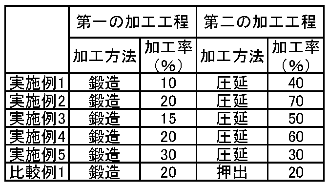
- the cylindrical sintered body (ingot) was processed under the processing conditions shown in Table 2. All were processed by cold working.
- the cylindrical sintered body obtained was cut and processed to form a tapered tip.
- the taper angle of the tip portion was adjusted to 60 degrees or more and 80 degrees or less.
- a cathode part for a discharge lamp was manufactured.
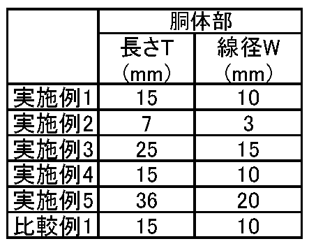
- Table 3 shows the sizes of the cathode parts.
- the crystal orientation, tungsten crystal size, and thorium crystal size were examined for the cathode parts according to the examples and comparative examples.
- the crystal orientation was measured by performing EBSD analysis at a position within 1 mm from the center 4 of the cross section in the length T direction of the body passing through the center 4 of the body of the cathode component.
- TFE-SEM thermal field emission scanning electron microscope
- JSM-6500F manufactured by JEOL Ltd.
- DigiView IV slow scan CCD camera manufactured by TSL Solution Co., Ltd.
- OIM Data Collection ver. 7.3x OIM Analysis server. 8.0 was used.
- the EBSD measurement conditions were an electron beam acceleration voltage of 20 kV, an irradiation current of 12 nA, and a sample inclination angle of 70 degrees.
- the measurement area is 90 ⁇ m ⁇ 90 ⁇ m, and the measurement interval is 0.3 ⁇ m / step.
- a cross section 5 passing through the center 4 of the body portion 2 was used as a measurement surface, and the cross section 5 was irradiated with an electron beam to obtain a diffraction pattern.
- the grain size map of EBSD was used for the measurement of the grain size of the tungsten crystal.
- the crystal grain map had a unit area of 90 ⁇ m ⁇ 90 ⁇ m. In the crystal grain map, those having two or more consecutive measurement points within 5 degrees of crystal orientation difference were identified as the same crystal grain. After determining the individual particle diameters, the average particle diameter D 50 and the particle diameter D 90 were determined.
- the grain size map of EBSD was also used for the measurement of the grain size of the thorium crystal.
- the unit area of the crystal grain map is 90 ⁇ m ⁇ 90 ⁇ m.
- a crystal grain in which two or more measurement points within a crystal orientation difference of 2 degrees are continuously present is identified as the same crystal grain.
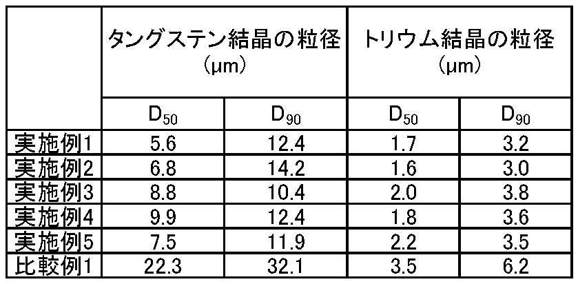
- the average particle diameter D 50 and the particle diameter D 90 were determined. The results are shown in Tables 4, 5, and 6.
- the preferential azimuth in the direction a in the cross section 5 was the ⁇ 101> azimuth.
- the preferential azimuth in the direction a of the cross section 5 was not the ⁇ 101> azimuth.
- the average grain size D 50 of the tungsten crystals was 20 ⁇ m or less, which satisfied D 90 ⁇ D 50 ⁇ 7 ⁇ m.
- the thorium crystal had an average particle diameter D 50 of 3 ⁇ m or less, which satisfied D 90 ⁇ D 50 ⁇ 2 ⁇ m.
- a discharge lamp was produced using a cathode part for a discharge lamp.
- the flicker life of the discharge lamp was measured.
- the durability test was performed by a lighting test.
- the lamp voltage during lighting was 40V and the lamp voltage during non-lighting was 20V.
- the lighting state was set to 3 hours and the non-lighting state was set to 2 hours, and this was repeated alternately.
- Flicker was defined as when the deviation of the lamp voltage in the lighting state or the non-lighting state was 1 V or more.
- the total lighting time until the flicker phenomenon occurred was defined as the flicker life.
- the average particle diameter D 50 ( ⁇ m) of the tungsten crystal was measured after 800 hours had passed.
- the average particle diameter D 50 was measured by using the cross section of the tip portion 3 and measuring a portion having a depth of 0.5 mm from the tip portion 3. The results are shown in Table 7.
- the flicker life of the discharge lamp according to the example was 800 hours or more, and the life was extended. This is because coarse particles are less likely to be formed in the cathode component.
- the increase rate of the average grain size D 50 of the tungsten crystals is smaller in Examples 3 to 5 than in Examples 1 and 2. Grain growth can be suppressed by using tungsten oxide WO 2.9 once like the second mixed raw material powder.
Landscapes
- Discharge Lamp (AREA)
- Powder Metallurgy (AREA)
Abstract
放電ランプ用カソード部品は、線径2mm以上35mm以下の胴体部と、胴体部から先細る先端部と、を具備する。カソード部品は、ThO2換算で0.5質量%以上3質量%以下のトリウムを含有するタングステン合金を含み、胴体部の中心を通るとともに胴体部の長さ方向に沿う断面における、中心から1mm以内に位置するとともに90μm×90μmの単位面積を有する領域の電子線後方散乱回折分析を行う場合、長さ方向のInverse Pole Figureマップにおいて、<101>方位に対する方位差が-15度以上15度以下の結晶方位を有するタングステン相の面積比が最も高い。
Description
実施形態は、放電ランプ用カソード部品および放電ランプに関する。
放電ランプは、低圧放電ランプと高圧放電ランプの2種類に大きく分けられる。低圧放電ランプは、一般照明、道路やトンネルなどに使われる特殊照明、塗料硬化装置、紫外線(UV)硬化装置、殺菌装置、半導体などの光洗浄装置など様々なアーク放電型の放電ランプが挙げられる。高圧放電ランプは、上下水の処理装置、一般照明、競技場などの屋外照明、UV硬化装置、半導体やプリント基板などの露光装置、ウエハ検査装置、プロジェクタなどの高圧水銀ランプ、メタルハライドランプ、超高圧水銀ランプ、キセノンランプ、ナトリウムランプなどが挙げられる。このように放電ランプは、照明装置、映像投影装置、製造装置などの様々な装置に用いられている。
例えば、放電ランプを用いた投射型表示装置が知られている。近年は、ホームシアターやデジタルシネマが普及している。これらは、プロジェクタと呼ばれる投射型表示装置を用いる。従来の投射型表示装は、放電ランプの電極の消耗により、ランプ寿命や射出される光のちらつきに影響を及ぼす。このような問題に対処するために、放電ランプの駆動方式として、パルス幅変調(PWM)駆動を採用することが知られている。このように、放電ランプの電極消耗は、制御回路により管理することができる。
放電ランプの電極を消耗すると、ランプ電圧が低下する。これにより、放電ランプから放出される光にばらつきが生じる。このような現象はフリッカー現象と呼ばれる。フリッカー現象は、映像のちらつきなどに影響を及ぼす。このため、高い耐久性を有する放電ランプ用電極が求められている。
また、放電ランプ用カソード部品の長さ方向(側面方向)の断面と線径方向(円周方向)の断面のタングステン結晶の粒径を制御する技術が知られている。上記技術を用いて製造されたカソード部品は、耐久性試験として、カソード部品に通電して加熱した状態で、電圧を印加し、10時間後のエミッション電流密度(mA/mm2)と100時間後のエミッション電流密度(mA/mm2)を測定することにより、優れた特性を有することが知られている。
放電ランプは、照明装置、映像投影装置、製造装置などの様々な装置に用いられている。放電ランプの電極が消耗するとランプ性能が低下する。ランプ性能が低下すると放電ランプの交換を必要とする。そのため、電極の更なる長寿命化が望まれている。従来の放電ランプ用カソード部品は、100時間程度では優れた耐久性を示すが、それを超える長時間では耐久性が低下する。
実施形態に係る放電ランプ用カソード部品は、線径2mm以上35mm以下の胴体部と、胴体部から先細る先端部と、を具備する。カソード部品は、ThO2換算で0.5質量%以上3質量%以下のトリウムを含有するタングステン合金を含み、胴体部の中心を通るとともに胴体部の長さ方向に沿う断面における、中心から1mm以内に位置するとともに90μm×90μmの単位面積を有する領域の電子線後方散乱回折分析を行う場合、長さ方向のInverse Pole Figureマップにおいて、<101>方位に対する方位差が-15度以上15度以下の結晶方位を有するタングステン相の面積比が最も高い。
以下、実施形態について、図面を参照して説明する。図面に記載された各構成要素の厚さと平面寸法との関係、各構成要素の厚さの比率等は現物と異なる場合がある。また、実施形態において、実質的に同一の構成要素には同一の符号を付し適宜説明を省略する。
図1は放電ランプ用カソード部品の一例を示す側面図である。放電ランプ用カソード部品1は、線径2mm以上35mm以下の胴体部2と、胴体部2から先細るように延在する先端部3と、を備えている。図1は、放電ランプ用カソード部品1と、胴体部2と、先端部3と、中心4と、胴体部2の線経Wと、胴体部2の長さTと、を示す。図2は胴体部2の中心4の長さ方向の断面の一例を示す図である。図2は、胴体部2の長さT方向(側面方向)に沿う方向aと、方向aに沿うとともに中心4を通る断面5と、断面5と垂直な方向b(胴体部2の線径W方向(円周方向))と、を示す。本明細書では、放電ランプ用カソード部品を単に「カソード部品」と示すこともある。
胴体部2は、円柱形状を有する。線径Wは円周方向断面の直径である。円周が楕円の場合、線径Wは最も大きな直径を示す。胴体部2の線径Wが2mm未満であると、放電ランプの発光が不足する可能性がある。線径Wが35mmを超えると、放電ランプの大型化を招く。そのため、線径Wは2mm以上35mm以下、さらには5mm以上20mm以下が好ましい。胴体部2の長さTは10mm以上600mm以下が好ましい。
先端部3は胴体部2から先細る形状を有する。そのため、先細り始める箇所から端部までの領域が先端部3となる。先端部3は、カソード部品1の方向aの断面において、鋭角形状を有する。カソード部品1はこのような形状に限定されず、カソード部品1の方向aの断面において、先端部3が例えばR形状、平面形状のような他の形状を有していてもよい。先端部3が先細り形状を有する場合、放電ランプの一対の電極部品間で効率よく放電することができる。
カソード部品は、酸化物(ThO2)換算で0.5質量%以上3質量%以下のトリウム(トリウム成分ともいう)を含有するタングステン合金からなる。含有量が0.5質量%未満では添加の効果が小さく、3質量%を超えると焼結性および加工性が低下する。そのため、トリウムの含有量は酸化物(ThO2)換算で0.5質量%以上3質量%以下、さらには0.8質量%以上2.5質量%以下が好ましい。
カソード部品1は、胴体部2の中心4を通るとともに胴体部2の長さT方向(方向a)に沿う断面5における、中心4から1mm以内に位置するとともに90μm×90μmの単位面積を有する領域の電子線後方散乱回折(EBSD)分析を行う場合、長さ方向の逆極点図(Inverse Pole Figure:IPF)マップにおいて、-15度以上15度以下の結晶方位を有するタングステン相の面積比が最も高い。
EBSDは、結晶試料に電子線を照射する。電子は回折され反射電子として試料から放出される。この回折パターンを投影し、投影されたパターンから結晶方位を測定することができる。X線回折(XRD)は複数の結晶における結晶方位の平均値を測定する方法である。これに対し、EBSDは個々の結晶の結晶方位を測定することができる。EBSDと同様の分析方法は、電子線後方散乱パターン(EBSP)分析と呼ばれることがある。
EBSD分析は、日本電子株式会社製の熱電界放射型走査電子顕微鏡(TFE-SEM)JSM-6500Fと株式会社TSLソリューション製のDigiViewIVスロースキャンCCDカメラ、OIM Data Collectionver.7.3x、OIM Analysisver.8.0を用いて行われる。
EBSD分析の測定条件は、電子線の加速電圧20kV、照射電流12nA、試料の傾斜角70度、測定領域の単位面積90μm×90μm、測定位置は中心4から1mm以内、測定間隔0.3μm/stepを含む。断面5が測定面であり、断面5へ電子線を照射し回折パターンを得る。測定試料の測定面は、表面粗さRaが0.8μm以下になるまで研磨される。
測定箇所は、胴体部2の中心4を通る長さT方向(方向a)の断面5とする。胴体部2の中心4は、胴体部2の線経Wの中点を通る直線と長さTの中点が通る直線が交差する点である。断面5は、中心4を通るとともに長さT方向(方向a)に水平な方向の断面である。
結晶方位は、基本ベクトルを用いて方向を示す。角括弧([ ])と角括弧に挟まれた数字の組み合わせからなる表記は特定の結晶方位のみを示す。山括弧(< >)と山括弧に挟まれた数字の組み合わせからなる表記は、特定の結晶方位とそれと等価な方向とを示す。例えば、<101>方位とは、[101]と等価な方向を含むことを示す。また、タングステン相の方向aへの優先方位が<101>方位であるということは、<101>方位がすべての結晶方位の中で最も割合が多いことを示す。
IPFマップとは、結晶方位マップのことである。IPFマップは、所定の結晶方位からずれた領域の割合を面積比で求めることができる。IPFマップは、前述のEBSD測定方法に準じて求めることができる。カラーマッピングにより、面積比を画像解析により求めやすくできる。
断面5において、タングステン相の優先方位が<101>方位である。これにより、タングステン結晶の異常粒成長を抑制できる。異常粒成長は、製造工程中または放電ランプ使用中にタングステン結晶が粗大になることである。トリウムはエミッター材である。トリウムはタングステン結晶同士の粒界に分布する。タングステン結晶が異常粒成長すると、トリウムの分布状態が変化する。これにより、フリッカー寿命や照度維持率が低下する。フリッカー寿命は、フリッカー現象が発生するまでの時間である。
実施形態の放電ランプ用カソード部品は、タングステン結晶の異常粒成長を抑制する。異常粒成長は、カソード部品の製造工程中だけでなく、放電ランプの使用中にも発生する。放電ランプに組み込む前のカソード部品が異常粒成長により形成された粗大粒を有していなくても、カソード部品の組み込み後の放電ランプの使用中に粗大粒を形成する。長さT方向(方向a)の断面5においてタングステン相の優先方位を制御することにより、異常粒成長を抑制できる。
断面5における中心から1mm以内に位置するとともに90μm×90μmの単位面積を有する領域のEBSD分析を行う場合、タングステン相の胴体部2の長さT方向(方向a)のIPFマップにおいて、<101>方位に対する方位差が-15度以上15度以下の結晶方位を有するタングステン相の面積比は50%以上であることが好ましい。
<101>方位に対する方位差が±15度以内であれば、<101>方位と同等の効果を得ることができる。<101>方位に対する方位差が±15度以内の結晶方位を有するタングステン相の面積比が50%未満の場合、特性向上の効果が不十分となる可能性がある。また、単位面積90μm×90μmの微小領域において上記タングステン相の面積比を制御することにより、異常粒成長を抑制する効果を高めることができる。これにより、フリッカー寿命を長くできる。<101>方位に対する方位差が±15度の範囲から外れると、所望の結晶方位以外の結晶方位を有するタングステン相の割合が増加する。
上記面積比の上限は80%以下であることが好ましい。80%を超えると、断面5に垂直な方向bの結晶方位を制御することが困難となる可能性がある。異なる結晶方位を有するタングステン相が存在することにより、粒成長の抑制効果を向上させることができる。このため、<101>方位に対する方位差が±15度以内の結晶方位を有するタングステン相の面積比は50%以上80%以下、さらには65%以上80%以下が好ましい。さらに好ましくは65%以上75%以下である。
長さT方向のIPFマップにおいて、<101>方位に対する方位差が-10度以上10度以下である結晶方位を有するタングステン相の面積比は、35%以上、さらには50%以上であることが好ましい。<101>方位に対する方位差が±10度以内である結晶方位を有するタングステン相の面積比が35%以上であるということは、<101>方位に近い結晶方位を有するタングステン相の面積比が高いことを示す。上記面積比は65%以下であることが好ましい。これにより、異常粒成長をさらに抑制することができる。
長さT方向のIPFマップにおいて、<101>方位に対する方位差が-5度以上5度以下の結晶方位を有するタングステン相の面積比は10%以上、さらには15%以上であることが好ましい。上記面積比は30%以下であることが好ましい。
以上のように、<101>方位に対する方位差が±15度以内、±10度以内、±5度以内の結晶方位を有するタングステン相の面積比がそれぞれの範囲を満たすことが好ましい。なお、それぞれの面積比は「±5度以内」→「±10度以内」→「±15度以内」の順で大きいことが好ましい。上記順に大きいということは、±5度以内の方位差を有する結晶方位を有するタングステン相、±6度以内ないし±10度以内の方位差を有する結晶方位を有するタングステン相、±11度以内ないし±15度以内の方位差を有する結晶方位を有するタングステン相がそれぞれ存在することを意味する。それぞれの面積比を制御することにより、異常粒成長の発生を抑制できる。
胴体部2の中心4を通るとともに長さT方向(方向a)の断面5における、中心から1mm以内に位置するとともに90μm×90μmの単位面積を有する領域のEBSD分析を行う場合、断面5と垂直な方向bのIPFマップにおいて、<111>方位に対する方位差が-15度以上15度以下の結晶方位を有するタングステン相の面積比が15%以上50%以下であることが好ましい。
<111>方位に対する方位差が±15度以内であれば、<111>方位と同等の効果を得ることができる。<111>方位に対する方位差が±15度以内の結晶方位を有していても、面積比が15%未満または50%を超えると特性向上の効果が不十分となる可能性がある。このため、面積比は15%以上50%以下、さらには18%以上40%以下が好ましい。単位面積90μm×90μmの微小領域で所定の結晶方位を有するタングステン相の面積比を制御することにより、異常粒成長を抑制する効果を高めることができる。これにより、フリッカー寿命を長くできる。
断面5と垂直な方向bのIPFマップにおいて、<111>方位に対する方位差が-10度以上10度以下の結晶方位を有するタングステン相の面積比が5%以上30%以下であることが好ましい。さらには、10%以上25%以下の範囲内であることが好ましい。
断面5と垂直な方向bのIPFマップにおいて、<111>方位に対する方位差が-5度以上5度以下の結晶方位を有するタングステン相の面積比が1%以上15%以下であることが好ましい。さらには、3%以上10%以下であることが好ましい。
<111>方位に対する方位差が±15度以内、±10度以内、±5度以内の結晶方位を有するタングステン相の面積比がそれぞれ上記範囲を満たすことが好ましい。それぞれの面積比は「±5度以内」→「±10度以内」→「±15度以内」の順に大きいことが好ましい。上記順に大きいということは、±5度以内、±6度以内ないし±10度以内、±11度以内ないし±15度以内の方位差を有する結晶方位を有するタングステン相がそれぞれ存在することを意味する。それぞれの面積比を制御することにより、異常粒成長の発生を抑制することができる。
図2の方向bは、長さT方向(方向a)の断面5と垂直な方向である。長さT方向(方向a)の断面5は上記結晶方位差の測定断面である。前述のように長さT方向(方向a)に最も強く配向する結晶方位は<101>方位である。断面5の垂直な方向bに<111>方位に近い結晶方位を有するタングステン相を所定の割合で存在させることにより、粒成長をさらに抑制できる。
以上のように方向によって結晶方位およびその面積比の制御が異なる。これにより、粒成長を抑制し、カソード部品を長寿命化することができる。このように結晶方位を制御することにより、例えば細長い結晶粒を形成できる。細長い結晶粒を形成することにより粒成長を抑制できる。
中心4から1mm以内に位置するとともに90μm×90μmの単位面積を有する領域をレーザ顕微鏡または走査型電子顕微鏡(SEM)で観察する場合、結晶粒の平均アスペクト比が2以上となる。レーザ顕微鏡またはSEMによる観察像に写る結晶の最も長い対角線を長径とする。長径の中心から垂直に伸ばした長さを短径とする。(長径+短径)/2=粒径とする。この作業を10粒以上行い、その平均値を平均粒径とする。長径/短径=アスペクト比とする。同様に10粒以上の平均値を平均アスペクト比とする。長径および短径は輪郭が全て写っている結晶を測定する。
タングステン結晶の平均粒径は20μm以下が好ましい。平均粒径が20μmを超えると、単位面積90μm×90μmの領域における配向割合(面積比)を制御し難くなる。平均粒径が大きいと、粒成長による耐久性の低下が起きやすい。トリウムはタングステン結晶同士の粒界に分布する。タングステン結晶の平均粒径を20μm以下とすることにより、エミッター材の分布状態を均一にすることができる。これにより、放電特性を向上させることができる。
タングステン結晶の平均粒径は、EBSD分析を行う場合の結晶粒マップを用いて求められる。タングステン結晶の結晶粒マップは、単位面積90μm×90μmの領域中で結晶方位角差が±5度以内の結晶方位を有するタングステン相の測定点が2点以上連続して存在する場合を同一結晶粒子として識別し、表示される。平均粒径は単位面積90μm×90μmの領域における識別された結晶粒子の面積から算出する。ここで粒径は円相当径である。単位面積90μm×90μmの領域からはみ出す粒子については単位面積90μm×90μmの領域の境界を結晶粒界として算出する。
平均粒径は、メジアン径(平均粒径D50)である。つまり、累積粒径である。タングステン結晶の平均粒径D50は、20μm以下、さらには15μm以下であることが好ましい。タングステン結晶の平均粒径D50の測定箇所は、断面5とする。断面5および線径W方向(方向b)の断面のどこを測定しても、タングステン結晶の平均粒径D50は20μm以下であることが好ましい。
タングステン結晶の粒度分布における小径側からの累積度数割合が90%であるときの粒径D90は25μm以下であることが好ましい。粒径D90の求め方は平均粒径D50と同様である。D90-D50≦7μm、であることが好ましい。粒径D90と平均粒径D50の差が7μm以下であるということは、粒径のばらつきがなく、粗大粒が無いことを示す。
タングステン結晶の平均粒径D50の下限値は特に限定されないが、3μm以上であることが好ましい。平均粒径D50が3μmより小さいと、粒径D90との差を7μm以下に制御しにくくなる。粒径D90についても、平均粒径D50を求めた結晶粒マップを使って測定する。
トリウム結晶のメジアン径(平均粒径D50)は3μm以下が好ましい。トリウム結晶の平均粒径も、タングステン結晶と同様にEBSDの結晶粒マップを用いて求められる。トリウム結晶の結晶粒マップは単位面積90μm×90μmの領域中で結晶方位角差が±2度以内の結晶方位を有するタングステン相の測定点が2点以上連続して存在する場合を同一結晶粒子として識別して表示される。トリウム結晶の平均粒径D50が3μmを超えると、エミッション特性にばらつきが生じやすい。トリウム結晶の粒径D90は5μm以下が好ましい。トリウム結晶の粒径D90と平均粒径D50の差は2μm以下であることが好ましい。トリウム結晶の粒径がD90-D50≦2μmを満たすことは、トリウム結晶の粒径のばらつきが小さいことを示す。
トリウム結晶はエミッションにより蒸発する。粗大なトリウム結晶があると、トリウム結晶の蒸発後に残る跡が大きな空洞になり、耐久性を低下させる。トリウム結晶の平均粒径D50は0.01μm以上が好ましい。あまり小さいと蒸発が早くなる可能性がある。
カソード部品1のタングステン結晶は再結晶組織を有していないことが好ましい。再結晶化前に上記結晶方位や粒径などを制御することが重要である。これにより、再結晶組織を有していても、タングステン結晶の異常粒成長を抑制できる。言い換えれば、実施形態のカソード部品は、再結晶化前のカソード部品である。
再結晶組織とは、再結晶温度で熱処理することにより、結晶内ひずみ(内部応力)を低減した組織のことである。トリウムを含有するタングステン合金の再結晶温度は1300K以上2000K以下(1027℃以上1727℃以下)である。カソード部品1は、先端部3を形成するための加工を施して形成される必要がある。また、胴体部2の線径Wの調整のために加工を施して形成される必要がある。これら加工により生じる歪を再結晶化熱処理で緩和できる。1300K以上2000K以下の温度で形成される再結晶を一次再結晶という。一次再結晶は熱処理前と比べて粒成長を伴う。2000Kを超える温度で形成される再結晶を二次再結晶という。二次再結晶は、一次再結晶よりも、さらに粒成長が起きる。一般的に二次再結晶の結晶粒は熱処理前に比べて30倍以上大きくなる。このため、再結晶の有無は粒径から判断することができる。放電ランプを点灯すると、カソード電極の温度は2000℃を超える温度まで上昇する。このため、カソード部品1は再結晶組織を有する。長時間使用し続けていると、高温状態が続くため、さらに粒成長しやすい使用環境である。
実施形態のカソード部品は、再結晶化前の結晶方位などを制御するため、粒成長を抑制できる。その結果、放電ランプのフリッカー寿命を長くできる。フリッカー寿命は例えば800時間以上であることが好ましい。
実施形態のカソード部品は、放電ランプに適用することができる。図3は放電ランプの構造例を示す図である。図3は、カソード部品1と、アノード部品6と、電極支持棒7と、ガラス管8と、を示す。
カソード部品1は一つの電極支持棒7に接続されている。アノード部品6は他の一つの電極支持棒7に接続されている。接続はろう付けなどによって行われる。カソード部品1とアノード部品6はガラス管8の中で対向して配置され、電極支持棒7の一部とともに封止されている。ガラス管8内部は真空に保たれている。
カソード部品1は低圧放電ランプ、高圧放電ランプのいずれの放電ランプにも適用できる。低圧放電ランプは、一般照明、道路やトンネルなどに使われる特殊照明、塗料硬化装置、UV硬化装置、殺菌装置、半導体などの光洗浄装置などに用いられる、様々なアーク放電型の放電ランプが挙げられる。高圧放電ランプは、上下水の処理装置、一般照明、競技場などの屋外照明、UV硬化装置、半導体やプリント基板などの露光装置、ウエハ検査装置、プロジェクタなどの高圧水銀ランプ、メタルハライドランプ、超高圧水銀ランプ、キセノンランプ、ナトリウムランプなどが挙げられる。このように放電ランプは、照明装置、映像投影装置、製造装置などの様々な装置に用いられている。実施形態のカソード部品は耐久性に優れているため、高圧放電ランプに適している。
放電ランプの出力は、例えば100Wないし10kWである。1000W未満の出力の放電ランプを低圧放電ランプとし、1000W以上の出力の放電ランプを高圧放電ランプとする。
放電ランプは、それぞれ用途に応じて設定された保証寿命を有する。保証寿命の一つにフリッカー寿命がある。フリッカー現象とは、前述のとおり放電ランプの出力がばらつくことであり、放電ランプの出力が100%になる電圧を印加しているにも関わらず、出力が低下する。
デジタルシネマ用放電ランプは、出力1kW以上7kW以下程度の放電ランプを用いて構成される。スクリーンサイズに合わせて、放電ランプの出力を選択する。スクリーンサイズが6mでは出力1.2kWである。スクリーンサイズが15mでは出力4kWである。スクリーンサイズが30mでは出力7kWである。出力1.2kWの放電ランプの定格寿命は3000時間程度に設定されている。出力4kWの放電ランプの定格寿命は1000時間程度に設定されている。出力7kWの放電ランプの定格寿命は300時間程度に設定されている。デジタルシネマ用放電ランプの寿命は出力が大きくなるに従い短い。このように、放電ランプの寿命は、用途や使用条件によって様々である。
従来の放電ランプ用カソード部品では、寿命の半分程度の期間が経過するとフリッカー現象が生じる。デジタルシネマ用放電ランプにフリッカー現象が生じると、画面のちらつきが生じ、きれいな画像を視認できないため、定格寿命の前に上記部品を交換する必要がある。実施形態のカソード部品は、放電ランプの使用中においてタングステン結晶の異常粒成長を抑制できる。このため、フリッカー現象の発生を抑制することができる。
デジタルシネマなどの投影型表示装置は、ちらつきが生じると画質が低下する。そのため、フリッカー現象の抑制要求が厳しい。このため、実施形態のカソード部品は、デジタルシネマ用放電ランプに好適である。ここではデジタルシネマ用放電ランプを例示するが、他の用途についても同様である。
次に、実施形態のカソード部品の製造方法例について説明する。実施形態のカソード部品の製造方法は、上記構成を有していれば特に限定されないが、歩留り良くカソード部品を製造する方法として次の方法が挙げられる。
まず、タングステン合金を製造するために、トリウムを含有するタングステン合金粉末を調製する。タングステン合金粉末の調製法は、例えば湿式法と乾式法が挙げられる。
湿式法では、まず、タングステン材料粉末を調製する工程を実施する。タングステン材料粉末は、タングステン酸アンモニウム(APT)粉末、金属タングステン粉末、酸化タングステン粉末が挙げられる。タングステン材料粉末は、これら1種でもよいし、2種以上を用いてもよい。タングステン酸アンモニウム粉末が比較的価格が安いことから好ましい。タングステン材料粉末は平均粒径5μm以下が好ましい。
タングステン酸アンモニウム粉末を使う場合、タングステン酸アンモニウム粉末を大気中または不活性雰囲気(窒素、アルゴンなど)中で400℃以上600℃以下の温度に加熱して、タングステン酸アンモニウム粉末を酸化タングステン粉末に変化させる。400℃未満の温度では、酸化タングステン粉末に十分に変化させられず、600℃を超える温度では、酸化タングステン粉末の粒子が粗大になり、後工程での酸化トリウム粉末との均一分散が困難となる。この工程により、酸化タングステン粉末を調製する。
次に、トリウム材料粉末と酸化タングステン粉末を溶液中に添加する工程を実施する。トリウム材料粉末は、金属トリウム粉末、酸化トリウム粉末、硝酸トリウム粉末が挙げられる。この中では、硝酸トリウム粉末が好ましい。硝酸トリウム粉末は液体中で均一に混合しやすい。この工程により、トリウム材料粉末と酸化タングステン粉末とを含有する溶液を調製する。最終的に目的とする酸化トリウム濃度と同じか、若干高めの濃度となるように添加することが好ましい。トリウム材料粉末は平均粒径5μm以下が好ましい。溶液は純水であることが好ましい。
次に、トリウム材料粉末と酸化タングステン粉末とを含有する溶液の液体成分を蒸発させる工程を実施する。次に、大気雰囲気中で400℃以上900℃以下の温度で加熱して、硝酸トリウムなどのトリウム材料粉末を酸化トリウム粉末に変化させる分解工程を実施する。この工程により、酸化トリウム粉末と酸化タングステン粉末とを含む混合粉末を調製することができる。得られた酸化トリウム粉末と酸化タングステン粉末とを含む混合粉末の酸化トリウム濃度を測定し、濃度が低い場合には、酸化タングステン粉末を追加することが好ましい。
次に、酸化トリウム粉末と酸化タングステン粉末とを含む混合粉末を、水素などの還元雰囲気中、750℃以上950℃以下の温度で加熱して酸化タングステン粉末を金属タングステン粉末に還元する工程を実施する。この工程により、酸化トリウム粉末を含有するタングステン粉末を調製することができる。
金属タングステン粉末とトリウム材料粉末とを混合する方法も有効である。金属タングステン粉末は、タングステン酸アンモニウム粉末から酸化タングステン粉末を製造し、得られた酸化タングステンを還元することにより形成されることが好ましい。タングステン酸アンモニウム粉末から酸化タングステン粉末に変化させるとき、得られる酸化タングステンは酸素欠損を有することが好ましい。酸化タングステンの組成は、WO3が安定である。酸素欠損があるとWO3-x、x>0、となる。酸素欠損があると、結晶構造にゆがみが形成される。その状態で還元して得られた金属タングステン粉末は、異常粒成長の抑制効果が高い。xの値は0.05≦x≦0.30の範囲内であることが好ましい。
タングステン酸アンモニウム粉末から酸化タングステン粉末を製造する工程は、不活性雰囲気中で加熱する工程が好ましい。不活性雰囲気とは、窒素雰囲気やアルゴン雰囲気である。xの値の制御のためには、不活性雰囲気中の酸素量を少なくする(例えば、1体積%以下)ことや、水素を混合することなどが挙げられる。熱処理温度は、400℃以上600℃以下の範囲内であることが好ましい。400℃未満では反応速度が遅く量産性が低下する。600℃を超えると粒成長し過ぎる可能性がある。
WO3-x粉末を還元する工程は、水素含有雰囲気で行うことが好ましい。熱処理温度は600℃以上800℃以下の範囲内であることが好ましい。熱処理温度が600℃未満では還元の速度が遅く量産性が低下する。800℃を超えると粒成長し過ぎる可能性がある。
次に、トリウム材料粉末と金属タングステン粉末とを含有する溶液の液体成分を蒸発させる工程を実施する。次に、大気雰囲気中で400℃以上900℃以下の温度で試料を加熱して、硝酸トリウムなどのトリウム材料粉末を酸化トリウム粉末に変化させる分解工程を実施する。この工程により、酸化トリウム粉末を含有するタングステン粉末を調製できる。
乾式法は、先ず、酸化トリウム粉末を用意する。次に、酸化トリウム粉末をボールミルにて粉砕混合する工程を実施する。この工程により、凝集された酸化トリウム粉末をほぐすことができ、凝集された酸化トリウム粉末を低減することができる。混合工程の際は、少量の金属タングステン粉末を添加してもよい。
粉砕混合された酸化トリウム粉末に対し、必要に応じ、篩を掛けて粉砕しきれなかった凝集粉または粗大粒を取り除くことが好ましい。篩掛けにより、最大径10μmを超える凝集粉または粗大粒を取り除くことが好ましい。
次に、金属タングステン粉末を混合する工程を実施する。最終的に目的とする酸化トリウム濃度になるように金属タングステン粉末を添加する。酸化トリウム粉末と金属タングステン粉末の混合粉末を混合容器に入れ、混合容器を回転させ均一に混合させる。このとき、円筒形状の混合容器を円周方向に回転させることにより、スムーズに混合することができる。この工程により、酸化トリウム粉末を含有するタングステン粉末を調製することができる。
以上のような、湿式法または乾式法により酸化トリウム粉末を含有するタングステン粉末を調製することができる。湿式法と乾式法では、湿式法の方が好ましい。乾式法は混合容器を回転させながら混合するため、原料粉末と容器が接触して不純物が混入しやすい。酸化トリウム粉末の含有量は0.5質量%以上3質量%以下である。
次に、得られた酸化トリウム粉末を含有するタングステン粉末を使って成形体を調製する。成形体を形成する際は、必要に応じ、バインダを使用してもよい。成形体は直径7mm以上50mm以下の円柱形状であることが好ましい。成形体の長さは任意である。
次に、成形体を予備焼結する工程を実施する。予備焼結は1250℃以上1500℃以下の温度で行うことが好ましい。この工程により、予備焼結体を得ることができる。
次に、予備焼結体を通電焼結する工程を実施する。通電焼結は、焼結体が2100℃以上2500℃以下の温度になるように通電することが好ましい。温度が2100℃未満では十分な緻密化ができず強度が低下する場合がある。2500℃を超えると、酸化トリウム粒子およびタングステン粒子が粒成長し過ぎて目的とする結晶組織が得られない場合がある。この工程により、酸化トリウム含有タングステン合金焼結体を得ることができる。予備焼結体が円柱形状を有していれば焼結体も円柱形状を有する。
次に、円柱状焼結体(インゴット)を、鍛造加工、圧延加工、押出加工などにより、線径を調整する第一の加工工程を実施する。第一の加工工程の加工率は10%以上30%以下の範囲内であることが好ましい。
第一の加工工程の次に第二の加工工程を行う。第二の加工工程は、加工率40%以上70%以下の圧延加工であることが好ましい。
加工率は、加工前の円柱状焼結体の断面積をA、加工後の円柱状焼結体の断面積をBとする場合、加工率=[(A-B)/A]×100%、により求められる。例えば、直径25mmの円柱状焼結体を直径20mmの円柱状焼結体に加工する場合の加工率を説明する。直径25mmの円の断面積Aは460.6mm2、直径20mmの円の断面積Bは314mm2であるから加工率は32%=[(460.6-314)/460.6]×100%となる。
第一の加工工程の加工率が10%以上30%以下であることは、第一の加工工程の前の円柱状焼結体(インゴット)の断面積を断面積Aとして求められる。第二の加工工程の加工率が40%以上70%以下であることは、第一の加工工程の後の円柱状焼結体の断面積を断面積Aとして求められる。
鍛造加工とは、ハンマーで焼結体を叩いて圧力を加える加工である。圧延加工とは、2つ以上のローラーで焼結体を挟みながら加工する方法である。押出加工は、強圧してダイス孔から押し出す方法である。
第一の加工工程は、鍛造加工、圧延加工、押出加工の1種または2種以上であることが好ましい。これらの加工方法は、線径Wを小さくできる。よって、円柱状焼結体中のポアを低減できる。第一の加工工程は、鍛造加工または押出加工が好ましい。鍛造加工または押出加工は、円柱状焼結体の円周全体を加工しやすいため、ポアの低減効果が高い。
第一の加工工程の加工率は10%以上30%以下である。加工率が10%未満であるとポアを低減する効果が小さい。加工率が30%を超えると結晶方位の制御が困難となる。第一の加工工程は、加工率が10%以上30%以下の範囲内であれば、複数回に分けて加工を行ってもよい。
第二の加工工程は、圧延加工である。圧延加工であると結晶方位を制御しやすい。圧延加工は、複数のローラーで挟みながら断面積を小さくする方法である。圧延加工のみで加工すると結晶方位を制御することができる。
鍛造加工はハンマーで叩くため結晶方位に部分的なばらつきが生じやすい。押出加工は、ダイスを通すときの応力が強いため、中央部と表面部での結晶方位に違いが生じやすい。圧延加工であると、ローラーからの応力を調整できるため、結晶方位を制御しやすい。
第二の加工工程において圧延加工の加工率は30%以上70%以下である。第一の加工工程後の断面積を断面積Aとして加工率を制御する。加工率が30%以上70%以下の範囲内であれば、1回の加工でもよいし、2回以上に分けてもよい。加工率が30%未満または70%を超えると、目的とする結晶方位が得られない。
第一の加工工程および第二の加工工程は、冷間加工であることが好ましい。冷間加工は、再結晶温度以下の温度で対象物を加工する方法である。再結晶温度以上の加熱状態で加工することを熱間加工という。熱間加工であると円柱状焼結体が再結晶化する。冷間加工であると再結晶化しない。再結晶化しない組織で結晶方位を制御することが重要である。
以上の工程により形成された線径2mm以上35mm以下の円柱状焼結体を、必要な長さに切断する。次に、先細る先端部3を形成する工程を実施する。先端部3の加工は、先端部3を所定のテーパ状に切削加工することにより行われる。必要に応じ、表面粗さRaが5μm以下になるように表面研磨加工を施す。
以上の工程により実施形態のカソード部品を製造できる。
放電ランプは次のように製造することができる。まず、カソード部品1を電極支持棒8に接続する。接続はろう付けなどによって行うことができる。アノード部品6が電極支持棒8に接続された部品を用意する。カソード部品1とアノード部品6はガラス管9の中で対向して配置し固定され、電極支持棒8の一部とともに封止する。ガラス管9内部は真空にする。放電ランプを製造する工程中に、必要に応じ、カソード部品の再結晶温度以上の熱処理を行ってもよい。
(実施例1ないし5、比較例1)
酸化トリウム粉末と金属タングステン粉末の混合原料粉末を以下の2種類を用意した。
酸化トリウム粉末と金属タングステン粉末の混合原料粉末を以下の2種類を用意した。
第一の混合原料粉末は、次の方法で調製した。まず、平均粒径2μmのタングステン酸アンモニウム(APT)粉末を大気中500℃の温度に加熱して、タングステン酸アンモニウム粉末を酸化タングステン粉末に変化させた。続いて、酸化タングステン粉末に、平均粒径3μmの硝酸トリウム粉末を添加し、純水を添加し、その後、15時間以上攪拌して均一に混合した。次に、水分を完全に蒸発させ、硝酸トリウム粉末と酸化タングステン粉末が均一に混合した混合粉末を得た。次に大気中520℃の温度で加熱して硝酸トリウム粉末を酸化トリウムに変化させた。次に、水素雰囲気中(還元雰囲気中)800℃の温度で熱処理して酸化タングステン粉末を金属タングステン粉末に還元した。これにより、酸化トリウム粉末と金属タングステン粉末の第一の混合原料粉末を調製した。
第二の混合原料粉末は、次の方法で調製した。まず、平均粒径2μmのAPT粉末を窒素雰囲気中450℃の温度に加熱して、タングステン酸アンモニウム粉末を酸化タングステン粉末に変化させた。このとき、窒素雰囲気に水素を混合することにより、得られた酸化タングステン粉末の組成はWO2.9であった。続いて、水素雰囲気中(還元雰囲気中)740℃の温度で熱処理して酸化タングステンWO2.9粉末を金属タングステン粉末に還元した。これにより、金属タングステン粉末を調製した。
次に、硝酸トリウム粉末と酸化タングステンWO2.9粉末を均一に混合した混合粉末を調製した。次に大気中520℃の温度で加熱して硝酸トリウム粉末を酸化トリウムに変化させた。次に、水素雰囲気中(還元雰囲気中)800℃の温度で熱処理した。これにより、酸化トリウム粉末と金属タングステン粉末の第二の混合原料粉末を調製した。
第一の混合原料粉末、第二の混合原料粉末を使って、表1に示す円柱状焼結体(インゴット)を形成した。第一の混合原料粉末および第二の混合原料粉末のトリウム量は、タングステン粉末を製造する際に添加する硝酸トリウムの添加量を変えることにより調製した。

次に、円柱状焼結体(インゴット)を表2に示す加工条件で加工した。いずれも冷間加工で加工した。
以上の工程により、得られた円柱状焼結体を切断加工し、先細る先端部を形成した。先端部のテーパ角度は60度以上80度以下に調整した。これにより、放電ランプ用カソード部品を製造した。カソード部品のサイズを表3に示す。
実施例および比較例に係るカソード部品に対し、結晶方位、タングステン結晶サイズ、トリウム結晶サイズを調べた。
結晶方位は、カソード部品の胴体部の中心4を通る胴体部の長さT方向の断面の中心4から1mm以内の位置でEBSD分析を行うことにより測定した。
EBSD分析では、日本電子株式会社製の熱電界放射型走査電子顕微鏡(TFE-SEM)JSM-6500Fと株式会社TSLソリューション製のDigiViewIVスロースキャンCCDカメラ、OIM Data Collectionver.7.3x、OIM Analysisver.8.0を使用した。EBSDの測定条件は、電子線の加速電圧20kV、照射電流12nA、試料の傾斜角を70度とした。測定領域は90μm×90μm、測定間隔は0.3μm/stepである。胴体部2の中心4を通る断面5を測定面とし、断面5へ電子線を照射し回折パターンを得た。
EBSD分析により、断面5の方向aに優先配向している結晶方位が<101>方位であるかを調べた。方向aのIPFマップにより、<101>方位に対する方位差が±15度以内の結晶方位を有するタングステン相の面積比、±10度以内の結晶方位を有するタングステン相の面積比、±5度以内の結晶方位を有するタングステン相の面積比を求めた。IPFマップを用いて断面5に垂直な方向bの結晶方位<111>方位に対する方位差が±15度以内の結晶方位を有するタングステン相、±10度以内の結晶方位を有するタングステン相の面積比、±5度以内の結晶方位を有するタングステン相の面積比を求めた。
タングステン結晶の粒径の測定は、EBSDの結晶粒マップを用いた。結晶粒マップは単位面積90μm×90μmとした。結晶粒マップの中で結晶方位角差5度以内の測定点が2点以上連続して存在するものを同一結晶粒子と識別した。個々の粒径を求めた後、平均粒径D50、粒径D90を求めた。
トリウム結晶の粒径の測定についてもEBSDの結晶粒マップを用いた。結晶粒マップは単位面積90μm×90μmとする。結晶粒マップの中で結晶方位角差2度以内の測定点が2点以上連続して存在するものを同一結晶粒子と識別した。個々の粒径を求めた後、平均粒径D50、粒径D90を求めた。その結果を表4、表5、表6に示す。


実施例に係る放電ランプ用カソード部品は、断面5において方向aの優先方位は<101>方位であった。それに対し、比較例1は断面5の方向aの優先方位は<101>方位ではなかった。
実施例はタングステン結晶の平均粒径D50は20μm以下であり、D90-D50≦7μmを満たしていた。トリウム結晶の平均粒径D50は3μm以下であり、D90-D50≦2μmを満たしていた。
次に、放電ランプ用カソード部品の耐久性を調べた。まず、放電ランプ用カソード部品を用いて放電ランプを作製した。耐久性試験として放電ランプのフリッカー寿命を測定した。耐久性試験は、点灯試験により実施した。点灯時のランプ電圧を40V、非点灯時のランプ電圧を20Vとした。点灯状態を3時間、非点灯状態を2時間とし、これを交互に繰り返した。点灯状態または非点灯状態のランプ電圧のずれが1V以上となったときをフリッカーが発生したと定義した。フリッカー現象が発生するまでの点灯時間の合計をフリッカー寿命とした。
同条件で800時間経過後にタングステン結晶の平均粒径D50(μm)を測定した。平均粒径D50の測定は、先端部3の断面を用い、先端部3から深さ0.5mmの箇所を測定した。その結果を表7に示す。
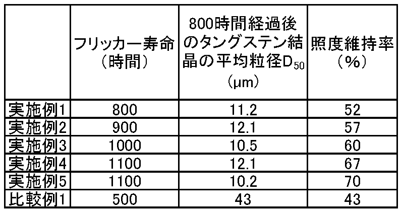
表からわかる通り、実施例に係る放電ランプのフリッカー寿命は800時間以上であり寿命が延びた。これはカソード部品に粗大粒が形成されにくいためである。実施例1、2よりも、実施例3ないし5の方がタングステン結晶の平均粒径D50の増加割合が小さい。第二の混合原料粉末のように一旦酸化タングステンWO2.9を使った方が粒成長を抑制できる。
以上、本発明のいくつかの実施形態を例示したが、これらの実施形態は、例として提示したものであり、発明の範囲を限定することは意図していない。これら新規な実施形態は、その他の様々な形態で実施されることが可能であり、発明の要旨を逸脱しない範囲で、種々の省略、置き換え、変更などを行うことができる。これら実施形態やその変形例は、発明の範囲や要旨に含まれるとともに、特許請求の範囲に記載された発明とその均等の範囲に含まれる。前述の各実施形態は、相互に組み合わせて実施することができる。
Claims (17)
- 線径2mm以上35mm以下の胴体部と、前記胴体部から先細る先端部と、を具備する放電ランプ用カソード部品であって、
前記カソード部品は、ThO2換算で0.5質量%以上3質量%以下のトリウムを含有するタングステン合金を含み、
前記胴体部の中心を通るとともに前記胴体部の長さ方向に沿う断面における、前記中心から1mm以内に位置するとともに90μm×90μmの単位面積を有する領域の電子線後方散乱回折分析を行う場合、前記長さ方向のInverse Pole Figureマップにおいて、<101>方位に対する方位差が-15度以上15度以下の結晶方位を有するタングステン相の面積比が最も高い、放電ランプ用カソード部品。 - 前記電子線後方散乱回折分析を行う場合、前記長さ方向のInverse Pole Figureマップにおいて、<101>方位に対する方位差が-15度以上15度以下の結晶方位を有するタングステン相の面積比が50%以上である、請求項1に記載のカソード部品。
- 前記電子線後方散乱回折分析を行う場合、前記長さ方向のInverse Pole Figureマップにおいて、<101>方位に対する方位差が-15度以上15度以下の結晶方位を有するタングステン相の面積比が60%以上80%以下である、請求項1に記載のカソード部品。
- 前記電子線後方散乱回折分析を行う場合、前記長さ方向のInverse Pole Figureマップにおいて、<101>方位に対する方位差が-10度以上10度以下の結晶方位を有するタングステン相の面積比が35%以上である、請求項1に記載のカソード部品。
- 前記電子線後方散乱回折分析を行う場合、前記長さ方向のInverse Pole Figureマップにおいて、<101>方位に対する方位差が-10度以上10度以下の結晶方位を有するタングステン相の面積比が50%以上である、請求項1に記載のカソード部品。
- 前記電子線後方散乱回折分析を行う場合、前記長さ方向のInverse Pole Figureマップにおいて、<101>方位に対する方位差が-5度以上5度以下の結晶方位を有するタングステン相の面積比が10%以上30%以下である、請求項1に記載のカソード部品。
- 前記電子線後方散乱回折分析を行う場合、前記長さ方向のInverse Pole Figureマップにおいて、<101>方位に対する方位差が-5度以上5度以下の結晶方位を有するタングステン相の面積比が15%以上30%以下である、請求項1に記載のカソード部品。
- 前記電子線後方散乱回折分析を行う場合、前記断面に垂直な方向のInverse Pole Figureマップにおいて、<111>方位に対する方位差が-15度以上15度以下の結晶方位を有するタングステン相の面積比が15%以上50%以下である、請求項1に記載のカソード部品。
- 前記電子線後方散乱回折分析を行う場合、前記断面に垂直な方向のInverse Pole Figureマップにおいて、<111>方位に対する方位差が-10度以上10度以下の結晶方位を有するタングステン相の面積比が5%以上30%以下である、請求項1に記載のカソード部品。
- 前記電子線後方散乱回折分析を行う場合、前記断面に垂直な方向のInverse Pole Figureマップにおいて、<111>方位に対する方位差が-5度以上5度以下の結晶方位を有するタングステン相の面積比が1%以上15%以下である、請求項1に記載のカソード部品。
- 前記電子線後方散乱回折分析を行う場合、前記断面に垂直な方向のInverse Pole Figureマップにおいて、<111>方位に対する方位差が-5度以上5度以下の結晶方位を有するタングステン相の面積比が3%以上10%以下である、請求項1に記載のカソード部品。
- 前記カソード部品は、複数のタングステン結晶を有し、
前記タングステン結晶のメジアン径は、20μm以下である、請求項1に記載のカソード部品。 - 前記カソード部品は、複数のトリウム結晶を有し、
前記トリウム結晶のメジアン径は、3μm以下である、請求項1に記載のカソード部品。 - 前記カソード部品は、複数のタングステン結晶を有し、
前記タングステン結晶は、再結晶組織を有していない、請求項1に記載のカソード部品。 - 請求項1に記載の前記カソード部品を具備する、放電ランプ。
- デジタルシネマ用放電ランプである、請求項15に記載の放電ランプ。
- フリッカー寿命が800時間以上である、請求項15に記載の放電ランプ。
Priority Applications (2)
| Application Number | Priority Date | Filing Date | Title |
|---|---|---|---|
| JP2020557563A JP6972383B2 (ja) | 2018-11-19 | 2019-11-19 | 放電ランプ用カソード部品および放電ランプ |
| CN201980037894.2A CN112272860B (zh) | 2018-11-19 | 2019-11-19 | 放电灯用阴极部件及放电灯 |
Applications Claiming Priority (2)
| Application Number | Priority Date | Filing Date | Title |
|---|---|---|---|
| JP2018-216344 | 2018-11-19 | ||
| JP2018216344 | 2018-11-19 |
Publications (1)
| Publication Number | Publication Date |
|---|---|
| WO2020105644A1 true WO2020105644A1 (ja) | 2020-05-28 |
Family
ID=70773121
Family Applications (1)
| Application Number | Title | Priority Date | Filing Date |
|---|---|---|---|
| PCT/JP2019/045311 Ceased WO2020105644A1 (ja) | 2018-11-19 | 2019-11-19 | 放電ランプ用カソード部品および放電ランプ |
Country Status (3)
| Country | Link |
|---|---|
| JP (1) | JP6972383B2 (ja) |
| CN (1) | CN112272860B (ja) |
| WO (1) | WO2020105644A1 (ja) |
Cited By (2)
| Publication number | Priority date | Publication date | Assignee | Title |
|---|---|---|---|---|
| WO2024204092A1 (ja) * | 2023-03-31 | 2024-10-03 | 株式会社 東芝 | タングステン線 |
| TWI878627B (zh) * | 2020-11-27 | 2025-04-01 | 日商松下知識產權經營股份有限公司 | 金屬線 |
Families Citing this family (1)
| Publication number | Priority date | Publication date | Assignee | Title |
|---|---|---|---|---|
| CN112262454B (zh) * | 2019-02-18 | 2024-04-09 | 株式会社东芝 | 放电灯用阴极部件、放电灯及放电灯用阴极部件的制造方法 |
Citations (6)
| Publication number | Priority date | Publication date | Assignee | Title |
|---|---|---|---|---|
| US20060049761A1 (en) * | 2004-09-07 | 2006-03-09 | Patent-Treuhand-Gesellschaft Fur Elektrisch Gluhlampen | Process for producing an electrode for high-pressure discharge lamps, and an electrode and a high-pressure discharge lamp with such electrodes |
| JP2009259790A (ja) * | 2008-03-26 | 2009-11-05 | Harison Toshiba Lighting Corp | 高圧放電ランプ |
| WO2011108288A1 (ja) * | 2010-03-05 | 2011-09-09 | パナソニック株式会社 | 放電ランプ用電極、高圧放電ランプ、ランプユニットおよび投射型画像表示装置 |
| JP2012109192A (ja) * | 2010-10-21 | 2012-06-07 | Yumex Inc | ショートアーク放電灯用陰極およびアーク放電方法 |
| WO2014006779A1 (ja) * | 2012-07-03 | 2014-01-09 | 株式会社 東芝 | タングステン合金部品、ならびにそれを用いた放電ランプ、送信管およびマグネトロン |
| JP2014063655A (ja) * | 2012-09-21 | 2014-04-10 | Orc Manufacturing Co Ltd | 放電ランプ用電極の製造方法 |
Family Cites Families (3)
| Publication number | Priority date | Publication date | Assignee | Title |
|---|---|---|---|---|
| US7262553B2 (en) * | 2003-06-26 | 2007-08-28 | Matsushita Electric Industrial Co., Ltd. | High efficacy metal halide lamp with configured discharge chamber |
| JP5041349B2 (ja) * | 2010-04-23 | 2012-10-03 | ウシオ電機株式会社 | ショートアーク型放電ランプ |
| US9030100B2 (en) * | 2012-02-15 | 2015-05-12 | Kabushiki Kaisha Toshiba | Cathode component for discharge lamp |
-
2019
- 2019-11-19 JP JP2020557563A patent/JP6972383B2/ja active Active
- 2019-11-19 WO PCT/JP2019/045311 patent/WO2020105644A1/ja not_active Ceased
- 2019-11-19 CN CN201980037894.2A patent/CN112272860B/zh active Active
Patent Citations (6)
| Publication number | Priority date | Publication date | Assignee | Title |
|---|---|---|---|---|
| US20060049761A1 (en) * | 2004-09-07 | 2006-03-09 | Patent-Treuhand-Gesellschaft Fur Elektrisch Gluhlampen | Process for producing an electrode for high-pressure discharge lamps, and an electrode and a high-pressure discharge lamp with such electrodes |
| JP2009259790A (ja) * | 2008-03-26 | 2009-11-05 | Harison Toshiba Lighting Corp | 高圧放電ランプ |
| WO2011108288A1 (ja) * | 2010-03-05 | 2011-09-09 | パナソニック株式会社 | 放電ランプ用電極、高圧放電ランプ、ランプユニットおよび投射型画像表示装置 |
| JP2012109192A (ja) * | 2010-10-21 | 2012-06-07 | Yumex Inc | ショートアーク放電灯用陰極およびアーク放電方法 |
| WO2014006779A1 (ja) * | 2012-07-03 | 2014-01-09 | 株式会社 東芝 | タングステン合金部品、ならびにそれを用いた放電ランプ、送信管およびマグネトロン |
| JP2014063655A (ja) * | 2012-09-21 | 2014-04-10 | Orc Manufacturing Co Ltd | 放電ランプ用電極の製造方法 |
Cited By (2)
| Publication number | Priority date | Publication date | Assignee | Title |
|---|---|---|---|---|
| TWI878627B (zh) * | 2020-11-27 | 2025-04-01 | 日商松下知識產權經營股份有限公司 | 金屬線 |
| WO2024204092A1 (ja) * | 2023-03-31 | 2024-10-03 | 株式会社 東芝 | タングステン線 |
Also Published As
| Publication number | Publication date |
|---|---|
| CN112272860A (zh) | 2021-01-26 |
| CN112272860B (zh) | 2023-11-07 |
| JPWO2020105644A1 (ja) | 2021-05-13 |
| JP6972383B2 (ja) | 2021-11-24 |
Similar Documents
| Publication | Publication Date | Title |
|---|---|---|
| CN103975414B (zh) | 钨合金部件、以及使用该钨合金部件的放电灯、发射管和磁控管 | |
| JP6972383B2 (ja) | 放電ランプ用カソード部品および放電ランプ | |
| US10998157B2 (en) | Tungsten alloy part, and discharge lamp, transmitting tube, and magnetron using the same | |
| US10167536B2 (en) | Tungsten alloy, tungsten alloy part, discharge lamp, transmitting tube, and magnetron | |
| CN103987864B (zh) | 钨合金、以及使用该钨合金的钨合金部件、放电灯、发射管和磁控管 | |
| CN104115254B (zh) | 放电灯用阴极部件 | |
| JP7098812B2 (ja) | 放電ランプ用カソード部品、放電ランプ、および放電ランプ用カソード部品の製造方法 | |
| JP7043680B2 (ja) | 放電ランプ用カソード部品および放電ランプ | |
| JP7176121B2 (ja) | 放電ランプ用カソード部品および放電ランプ | |
| JP2013229179A (ja) | 放電ランプ用電極支持棒およびそれを用いた放電ランプ |
Legal Events
| Date | Code | Title | Description |
|---|---|---|---|
| 121 | Ep: the epo has been informed by wipo that ep was designated in this application |
Ref document number: 19886908 Country of ref document: EP Kind code of ref document: A1 |
|
| ENP | Entry into the national phase |
Ref document number: 2020557563 Country of ref document: JP Kind code of ref document: A |
|
| NENP | Non-entry into the national phase |
Ref country code: DE |
|
| 122 | Ep: pct application non-entry in european phase |
Ref document number: 19886908 Country of ref document: EP Kind code of ref document: A1 |