WO2020105520A1 - 評価装置、評価方法、及びプログラム。 - Google Patents
評価装置、評価方法、及びプログラム。Info
- Publication number
- WO2020105520A1 WO2020105520A1 PCT/JP2019/044458 JP2019044458W WO2020105520A1 WO 2020105520 A1 WO2020105520 A1 WO 2020105520A1 JP 2019044458 W JP2019044458 W JP 2019044458W WO 2020105520 A1 WO2020105520 A1 WO 2020105520A1
- Authority
- WO
- WIPO (PCT)
- Prior art keywords
- viewpoint
- image
- pixel value
- evaluation
- original image
- Prior art date
- Legal status (The legal status is an assumption and is not a legal conclusion. Google has not performed a legal analysis and makes no representation as to the accuracy of the status listed.)
- Ceased
Links
Images


Classifications
-
- H—ELECTRICITY
- H04—ELECTRIC COMMUNICATION TECHNIQUE
- H04N—PICTORIAL COMMUNICATION, e.g. TELEVISION
- H04N19/00—Methods or arrangements for coding, decoding, compressing or decompressing digital video signals
- H04N19/10—Methods or arrangements for coding, decoding, compressing or decompressing digital video signals using adaptive coding
- H04N19/102—Methods or arrangements for coding, decoding, compressing or decompressing digital video signals using adaptive coding characterised by the element, parameter or selection affected or controlled by the adaptive coding
- H04N19/103—Selection of coding mode or of prediction mode
-
- H—ELECTRICITY
- H04—ELECTRIC COMMUNICATION TECHNIQUE
- H04N—PICTORIAL COMMUNICATION, e.g. TELEVISION
- H04N13/00—Stereoscopic video systems; Multi-view video systems; Details thereof
- H04N13/10—Processing, recording or transmission of stereoscopic or multi-view image signals
- H04N13/106—Processing image signals
- H04N13/111—Transformation of image signals corresponding to virtual viewpoints, e.g. spatial image interpolation
-
- H—ELECTRICITY
- H04—ELECTRIC COMMUNICATION TECHNIQUE
- H04N—PICTORIAL COMMUNICATION, e.g. TELEVISION
- H04N17/00—Diagnosis, testing or measuring for television systems or their details
-
- H—ELECTRICITY
- H04—ELECTRIC COMMUNICATION TECHNIQUE
- H04N—PICTORIAL COMMUNICATION, e.g. TELEVISION
- H04N19/00—Methods or arrangements for coding, decoding, compressing or decompressing digital video signals
- H04N19/10—Methods or arrangements for coding, decoding, compressing or decompressing digital video signals using adaptive coding
- H04N19/134—Methods or arrangements for coding, decoding, compressing or decompressing digital video signals using adaptive coding characterised by the element, parameter or criterion affecting or controlling the adaptive coding
- H04N19/154—Measured or subjectively estimated visual quality after decoding, e.g. measurement of distortion
-
- H—ELECTRICITY
- H04—ELECTRIC COMMUNICATION TECHNIQUE
- H04N—PICTORIAL COMMUNICATION, e.g. TELEVISION
- H04N19/00—Methods or arrangements for coding, decoding, compressing or decompressing digital video signals
- H04N19/10—Methods or arrangements for coding, decoding, compressing or decompressing digital video signals using adaptive coding
- H04N19/169—Methods or arrangements for coding, decoding, compressing or decompressing digital video signals using adaptive coding characterised by the coding unit, i.e. the structural portion or semantic portion of the video signal being the object or the subject of the adaptive coding
- H04N19/17—Methods or arrangements for coding, decoding, compressing or decompressing digital video signals using adaptive coding characterised by the coding unit, i.e. the structural portion or semantic portion of the video signal being the object or the subject of the adaptive coding the unit being an image region, e.g. an object
- H04N19/176—Methods or arrangements for coding, decoding, compressing or decompressing digital video signals using adaptive coding characterised by the coding unit, i.e. the structural portion or semantic portion of the video signal being the object or the subject of the adaptive coding the unit being an image region, e.g. an object the region being a block, e.g. a macroblock
-
- H—ELECTRICITY
- H04—ELECTRIC COMMUNICATION TECHNIQUE
- H04N—PICTORIAL COMMUNICATION, e.g. TELEVISION
- H04N19/00—Methods or arrangements for coding, decoding, compressing or decompressing digital video signals
- H04N19/10—Methods or arrangements for coding, decoding, compressing or decompressing digital video signals using adaptive coding
- H04N19/169—Methods or arrangements for coding, decoding, compressing or decompressing digital video signals using adaptive coding characterised by the coding unit, i.e. the structural portion or semantic portion of the video signal being the object or the subject of the adaptive coding
- H04N19/182—Methods or arrangements for coding, decoding, compressing or decompressing digital video signals using adaptive coding characterised by the coding unit, i.e. the structural portion or semantic portion of the video signal being the object or the subject of the adaptive coding the unit being a pixel
-
- H—ELECTRICITY
- H04—ELECTRIC COMMUNICATION TECHNIQUE
- H04N—PICTORIAL COMMUNICATION, e.g. TELEVISION
- H04N19/00—Methods or arrangements for coding, decoding, compressing or decompressing digital video signals
- H04N19/50—Methods or arrangements for coding, decoding, compressing or decompressing digital video signals using predictive coding
- H04N19/597—Methods or arrangements for coding, decoding, compressing or decompressing digital video signals using predictive coding specially adapted for multi-view video sequence encoding
Definitions
- the present invention relates to an evaluation device, an evaluation method, and a program.
- linear blending two images captured by two adjacent cameras are linearly complemented to generate an image for a viewpoint (hereinafter, referred to as “intermediate viewpoint”) located in the middle of these cameras.
- a viewpoint hereinafter, referred to as “intermediate viewpoint” located in the middle of these cameras.
- a method for example, Non-Patent Document 1.
- a display that realizes naked-eye 3D (three-dimensional) display using this linear blending is called a linear blending display (for example, Non-Patent Document 2).
- the linear blending display can display different light rays depending on the direction of the viewpoint.
- the linear blending display generates an image corresponding to an intermediate viewpoint from a multi-viewpoint image captured by a camera array, and outputs an image according to the position of the viewpoint.
- an image input to the linear blending display will be referred to as an “input viewpoint image”, and an image generated from the input viewpoint image by linear blending will be referred to as an “intermediate viewpoint image”.
- W and H represent the number of pixels in the horizontal direction and the number of pixels in the vertical direction in the encoding target block, respectively.
- d (x, y) is the difference value between the pixel value of the original image and the pixel value of the decoded image at the pixel at the coordinates (x, y) in the block to be encoded.
- the coding mode is selected so as to minimize the cost function of adding the squared error SE and the estimated code amount at a constant ratio.
- FIG. 6A and FIG. 6B show two distortion amounts in images for viewpoints A and B, which are adjacent viewpoints, and distortion amounts in intermediate viewpoint images of viewpoints A and B. It is an example of a case.
- the intermediate viewpoint is an arbitrary viewpoint included in a set of viewpoints located between the two viewpoints.
- black circles represent pixel values of the original image
- white circles represent pixel values of the decoded image.
- the arrow extending from the pixel value of the original image to the pixel value of the decoded image represents the difference between the two.
- the difference value at the image coordinates (x, y) with respect to the viewpoint A is represented by d (x, y)
- the difference value at the image coordinates (x, y) with respect to the viewpoint B is represented by d ⁇ (x, y). ..
- the difference value d (x, y) between the original image and the decoded image at the viewpoint A is the same in case 1 (FIG. 6 (A)) and case 2 (FIG. 6 (B)).
- the difference value d ⁇ (x, y) between the original image and the decoded image at the viewpoint B has different signs in case 1 and case 2, but their absolute values are the same. Therefore, when the squared error is calculated for each viewpoint according to the conventional evaluation method, the case 1 and the case 2 have the same evaluation value and the same coding mode is selected. However, the coding distortions in Case 1 and Case 2 should be evaluated separately from the two viewpoints described below.
- the fixed intermediate viewpoint image is an image in which the image for viewpoint A and the image for viewpoint B are linearly blended. Therefore, the amount of coding distortion changes according to the position of the intermediate viewpoint.
- FIG. 6A in case 1, the magnitude relationship between the pixel value of the original image and the pixel value of the decoded image is reversed between viewpoint A and viewpoint B. As a result, the amount of coding distortion in the intermediate viewpoint image is smaller than the amount of distortion in viewpoint A and the amount of distortion in viewpoint B.
- FIG. 6A in case 1, the magnitude relationship between the pixel value of the original image and the pixel value of the decoded image is reversed between viewpoint A and viewpoint B.
- case 2 the magnitude relationship between the pixel value of the original image and the pixel value of the decoded image does not reverse between viewpoint A and viewpoint B.
- the distortion amount of the encoding distortion in the intermediate viewpoint image becomes an intermediate distortion amount between the distortion amount at viewpoint A and the distortion amount at viewpoint B. Therefore, in case 1 and case 2, the case 1 has a smaller amount of coding distortion in the intermediate viewpoint image.
- the encoding that outputs the evaluation value of the encoding distortion in Case 2 is output. It is desirable that the mode be selected preferentially. Note that the display similar to that when no encoding is performed is almost the same as the display when the intermediate viewpoint image is generated using the original image.
- the encoding mode corresponding to case 1 is displayed such that the change in the pixel value at the time of moving the viewpoint is originally intended.
- the encoding mode should be determined in consideration of the balance between both cases 1 and 2 depending on the viewing mode and the content. For example, when the audience's viewpoint is fixed to some extent, such as in a movie theater, or when the viewing distance is long and the change in the line of sight angle is small, the coding mode corresponding to Case 1 is preferentially selected. It is desirable that the encoding mode corresponding to Case 2 is preferentially selected when the spectator constantly moves around, when the viewing distance is short, and the angle of the line of sight when moving is large.
- the evaluation value for the coding distortion in case 1 and the evaluation value for the coding distortion in case 2 are different from each other. They are the same and cannot be distinguished. Therefore, when the conventional evaluation method is used for the input viewpoint image, the encoding mode corresponding to the case 1 or the case 2 cannot be preferentially selected at the time of encoding, so that the subjective image quality is maximized. There is a problem that you cannot do it.
- the present invention has been made in view of such a situation, and an object thereof is to provide a technique capable of improving the subjective image quality of the entire image displayed by the linear blending display, that is, the input viewpoint image and the intermediate viewpoint image.
- One aspect of the present invention is an evaluation device that evaluates the encoding quality of encoded data of an image for a first viewpoint in a multi-viewpoint image, the pixel value of an original image for the first viewpoint, and Pixel values obtained from the encoded data relating to the viewpoint, pixel values of the original image for the second viewpoint different from the first viewpoint, and pixels obtained from the encoded data relating to the second viewpoint
- the evaluation device includes an evaluation unit that evaluates the coding quality of the coded data according to the first viewpoint by associating a value with a value.
- one aspect of the present invention is the evaluation device described above, wherein the evaluation unit is a pixel value of an original image with respect to the second viewpoint, and a pixel obtained from encoded data according to the second viewpoint.
- the evaluation unit is a pixel value of an original image with respect to the second viewpoint, and a pixel obtained from encoded data according to the second viewpoint.
- one aspect of the present invention is the above evaluation device, wherein the third viewpoint is an arbitrary viewpoint included in a set of viewpoints located between the first viewpoint and the second viewpoint.
- the evaluation unit determines the pixel value of the image for the third viewpoint based on the original image for the first viewpoint and the original image for the second viewpoint, and the encoded data according to the first viewpoint.
- the first viewpoint by using the difference value between the pixel value of the image for the third viewpoint based on the pixel value obtained and the pixel value obtained from the encoded data relating to the second viewpoint. Evaluate the coding quality of the coded data.
- one aspect of the present invention is the above evaluation device, wherein the third viewpoint is an arbitrary viewpoint included in a set of viewpoints located between the first viewpoint and the second viewpoint.
- the evaluation unit the pixel value of the original image for the first viewpoint, the pixel value of the original image for the second viewpoint, the original image for the first viewpoint and the original image for the second viewpoint Based on the pixel values of the image for the third viewpoint, the pixel value obtained from the encoded data according to the first viewpoint, and the second viewpoint.
- a pixel value obtained from the encoded data according to the first viewpoint Based on a pixel value obtained from the encoded data according to the first viewpoint, a pixel value obtained from the encoded data according to the first viewpoint, and a pixel value obtained from the encoded data according to the second viewpoint
- the encoding quality of the encoded data according to the first viewpoint is evaluated using the obtained pixel values of the image for the third viewpoint and the change amounts of at least two pixel values.
- one aspect of the present invention is the above-described evaluation device, wherein the evaluation unit uses the amount of change between pixel values of the image with respect to the third viewpoint, and uses the encoded data according to the first viewpoint. Evaluate the coding quality of.
- one aspect of the present invention is the above-described evaluation device, wherein the evaluation unit uses the value of SE LBD calculated by the following evaluation formula to encode the coded data according to the first viewpoint. Evaluate quality.
- D (x, y) is the difference between the pixel value of the coordinates (x, y) in the original image for the first viewpoint and the pixel value of the coordinates (x, y) in the decoded image for the first viewpoint.
- d ⁇ (x, y) is a pixel value of coordinates (x, y) in the original image for the second viewpoint and a pixel value of coordinates (x, y) in the decoded image for the second viewpoint.
- one aspect of the present invention is an evaluation method for evaluating the coding quality of coded data of an image for a first viewpoint in a multi-viewpoint image, wherein the pixel value of the original image for the first viewpoint, and Pixel values obtained from the encoded data relating to the first viewpoint, pixel values of the original image for the second viewpoint different from the first viewpoint, and obtained from the encoded data relating to the second viewpoint.
- the evaluation method includes an evaluation step of evaluating the coding quality of the coded data according to the first viewpoint by associating the pixel value with the pixel value.
- one aspect of the present invention is a program for causing a computer to function as the above-described evaluation device.
- the present invention it is possible to improve the subjective image quality of the entire image displayed by the linear blending display, that is, the input viewpoint image and the intermediate viewpoint image.
- FIG. 4 is a diagram for explaining an input image subjected to linear blending. It is a figure for demonstrating the encoding object block encoded by the evaluation apparatus 1 which concerns on one Embodiment of this invention. It is a figure for demonstrating the encoding distortion in the intermediate viewpoint image by linear blending. It is a figure for demonstrating the encoding distortion in the intermediate viewpoint image by linear blending.
- the evaluation device described below evaluates the coding distortion when the input viewpoint image is coded.
- the evaluation device and the like described below evaluate not only the encoded image but also the encoding distortion of the encoded image in consideration of the encoding distortion of the viewpoint estimated using the encoded image. I do.
- This evaluation result can be used not only for evaluating the multi-view video itself, but also as an index for determining a coding parameter when coding the multi-view video, for example.
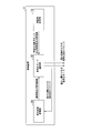
- FIG. 1 is a block diagram showing a functional configuration of an evaluation device 1 according to an embodiment of the present invention.
- the evaluation device 1 is configured to include an original image storage unit 10, a decoded image storage unit 20, and an encoding mode selection unit 30.
- the evaluation device 1 is implemented, for example, as a part of an encoder.
- the original image storage unit 10 stores the original image to be encoded.
- the decoded image storage unit 20 stores a decoded image that is a decoded image of the encoded original image.
- the original image storage unit 10 and the decoded image storage unit 20 are realized by, for example, flash memory, HDD (Hard Disk Drive), SDD (Solid State Drive), RAM (Random Access Memory; readable / writable memory), registers, and the like. ..
- the encoding mode selection unit 30 acquires information indicating the encoding target block and the original image for the adjacent viewpoint from the original image storage unit 10. Further, the encoding mode selection unit 30 acquires the decoded image for the adjacent viewpoint from the decoded image storage unit 20. The coding mode selection unit 30 calculates the distortion amount (change amount) of the coding distortion based on the information indicating the coding target block, the original image for the adjacent viewpoint, and the decoded image for the adjacent viewpoint. The coding mode selection unit 30 selects the coding mode that minimizes the distortion amount. The coding mode selection unit 30 uses the H.264 standard. Similar to the selection of the coding mode performed in H.265 / HEVC (High Efficiency Video Coding), the cost (distortion amount) evaluation formula is calculated each time one coding mode is determined.
- H.264 standard Similar to the selection of the coding mode performed in H.265 / HEVC (High Efficiency Video Coding), the cost (distortion amount) evaluation formula is calculated each time one coding mode is
- the coding mode selection unit 30 obtains a coded block and a decoded block by performing coding and decoding on the coding target block according to the selected coding mode.
- the coding mode selection unit 30 outputs the information indicating the coding mode in which the distortion amount is the minimum and the coded block in which the distortion amount is the minimum to an external device. Further, the coding mode selection unit 30 stores the decoded block having the smallest distortion amount in the decoded image storage unit 20.
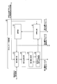
- FIG. 2 is a block diagram showing a functional configuration of the coding mode selection unit 30 of the evaluation device 1 according to the embodiment of the present invention.
- the coding mode selection unit 30 includes a coding unit 31, a decoding unit 32, a difference calculation unit 33, a distortion amount calculation unit 34, a distortion amount comparison unit 35, and a coding mode.
- the distortion amount storage unit 36 is included.
- the encoding unit 31 acquires information indicating the encoding target block and the original image for the adjacent viewpoint from the original image storage unit 10.
- the encoding unit 31 determines the encoding mode to be tried from the encoding modes stored in the encoding mode / distortion amount storage unit 36.
- the encoding unit 31 obtains an encoded block by encoding the target block to be encoded according to the determined encoding mode.
- the encoding unit 31 outputs the encoded block to the decoding unit 32. Further, the encoding unit 31 outputs the encoded block having the minimum distortion amount, which is obtained by repeating the above processing, to an external device.
- the decoding unit 32 acquires the encoded block output from the encoding unit 31.
- the decoding unit 32 obtains a decoded block by decoding the coded block.
- the decoding unit 32 outputs the decoded block to the difference calculation unit 33.
- the encoding unit 31 outputs the decoded block having the minimum distortion amount, which is obtained by repeating the above process, to the external device.
- the difference calculation unit 33 acquires, from the original image storage unit 10, information indicating the encoding target block and the original image for the adjacent viewpoint. Further, the difference calculation unit 33 acquires the decoded image for the adjacent viewpoint from the decoded image storage unit 20. Further, the difference calculation unit 33 acquires, from the decoding unit 32, a decoded block relating to the position of the coding target block and the adjacent viewpoint at the same position on the screen.
- the difference calculation unit 33 determines the difference value between the pixel value of the encoded block in the original image for the adjacent viewpoint and the pixel value of the block at the same position in the decoded image for the adjacent viewpoint, and the encoded block of the original image for the adjacent viewpoint.
- the difference value between the pixel value and the pixel value of the decoded block acquired from the decoding unit 32 is calculated for each pixel.
- the difference calculation unit 33 outputs the calculated difference value to the distortion amount calculation unit 34.
- the distortion amount calculation unit 34 acquires the difference value output from the difference calculation unit 33.
- the distortion amount calculation unit 34 calculates the distortion amount by substituting the acquired difference values into the evaluation formula and performing the calculation.
- the distortion amount calculation unit 34 outputs the calculation result of the calculation result by the evaluation formula to the distortion amount comparison unit 35.
- the distortion amount comparison unit 35 acquires the calculation result output from the distortion amount calculation unit 34.
- the distortion amount comparison unit 35 stores the acquired calculation result in the encoding mode / distortion amount storage unit 36. Further, the distortion amount comparison unit 35 acquires the minimum value of the calculation results so far from the encoding mode / distortion amount storage unit 36.
- the distortion amount comparison unit 35 compares the above calculation result with the minimum value of the calculation results so far.
- the distortion amount comparing unit 35 determines the value of the minimum value stored in the encoding mode / distortion amount storage unit 36 according to the calculation result. Update. Further, when the calculation result is smaller than the minimum value of the calculation results up to then, the distortion amount comparison unit 35 stores the encoding with the minimum distortion amount stored in the encoding mode / distortion amount storage unit 36. The value of the variable indicating the mode is updated with the value indicating the encoding mode determined by the encoding unit 31.
- the coding mode / distortion amount storage unit 36 stores the minimum value of the calculation results up to that point and the value of the variable indicating the coding mode with the minimum distortion amount.
- the encoding mode / distortion amount storage unit 36 is realized by, for example, a flash memory, an HDD, an SDD, a RAM, a register, or the like.
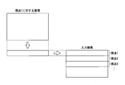
- the linearly blended input viewpoint image input to the evaluation device 1 is an image that is vertically stacked after subsampling images for a plurality of viewpoints, as shown in FIG.
- the original image with respect to the adjacent viewpoint and the decoded image with respect to the adjacent viewpoint, which are input to the difference calculation unit 33, are areas (partial images in the original image and the decoded image) corresponding to the same position as the target block on the screen. ).
- the encoding target block is the image area ar1 of the image for the viewpoint A
- the original image for the adjacent viewpoint and the decoded image for the adjacent viewpoint, which are input to the difference calculation unit 33 are the viewpoint B. May be only the part of the image area ar2 of the image.
- the coding block is a set of pixels having coordinates (x, y), as shown in FIG.
- the block to be encoded needs to be selected from images for viewpoints other than the viewpoint first encoded in the input image (that is, other than viewpoint 1 in FIG. 4). This is because, in the evaluation procedure described below, the evaluation of the coding target block is performed using the image for the adjacent viewpoint coded immediately before the viewpoint corresponding to the coding target block. Note that, for an image for a viewpoint that is first encoded, for example, in general, H.264 is used. It suffices to select the coding mode based on the calculation of the squared error, as is done in H.265 / HEVC.
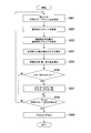
- FIG. 3 is a flowchart showing the operation of the coding mode selection unit 30 of the evaluation device 1 according to the embodiment of the present invention.
- W and H are the number of pixels, for example.
- the encoding unit 31 acquires information indicating the encoding target block and the original image for the adjacent viewpoint.
- the encoding unit 31 determines the value of Pred_tmp, which is a variable indicating the encoding mode to be newly tried (step S001), and then encodes the target block to be encoded in the encoding mode, thereby performing encoding. Get the block.
- the decoding unit 32 obtains a decoded block by decoding the coded block (step S002).
- the difference calculation unit 33 acquires, from the original image storage unit 10, information indicating the encoding target block and the original image for the adjacent viewpoint. Further, the difference calculation unit 33 acquires the decoded image for the adjacent viewpoint from the decoded image storage unit 20. In addition, the difference calculation unit 33 acquires, from the decoding unit 32, the decoded block relating to the adjacent viewpoint at the same position on the screen as the position of the block to be encoded (step S003). Then, the difference calculation unit 33 calculates the difference value between the pixel value of the original image and the pixel value of the decoded image and the difference value between the pixel value of the original image and the pixel value of the decoded block for each pixel ( Step S004).
- the distortion amount calculation unit 34 calculates the distortion amount by substituting the difference value calculated by the difference calculation unit 33 into the following expression (2), which is an evaluation expression, to perform calculation (step S005).
- D (x, y) is the difference between the pixel value of the coordinates (x, y) in the original image for the first viewpoint and the pixel value of the coordinates (x, y) in the decoded image for the first viewpoint.
- d ⁇ (x, y) is a pixel value of coordinates (x, y) in the original image for the second viewpoint and a pixel value of coordinates (x, y) in the decoded image for the second viewpoint.
- the distortion amount comparison unit 35 stores the calculation result calculated by the distortion amount calculation unit 34 in the encoding mode / distortion amount storage unit 36 as the value of cost_tmp which is a temporary variable. Then, the distortion amount comparison unit 35 compares cost_tmp with cost_min, which is the minimum value in the calculation result of Expression (2) up to that point (step S006).
- the distortion amount comparison unit 35 updates the cost_min value stored in the encoding mode / distortion amount storage unit 36 with the cost_tmp value.
- the distortion amount comparison unit 35 stores the value of Pred_min, which is a variable indicating the coding mode with the smallest distortion amount, which is stored in the coding mode / distortion amount storage unit 36. Is updated with the value of Pred_tmp (step S007).
- the coding mode selection unit 30 determines whether all coding modes have been tried (step S008). When all coding modes have been tried, the coding mode selection unit 30 outputs the value of Pred_min (step S009), and ends the operation shown in the flowchart of FIG. On the other hand, if there is a coding mode that has not been tried, the coding mode selection unit 30 repeats the same processing as above using the coding mode that has not been tried (return to step S001).
- the evaluation formula (2) is used as a substitute for the square error in the selection of the coding mode.
- the image quality can be evaluated by calculating the evaluation value of the entire image as follows. First, the squared error of the pixel value between the image for the first encoded viewpoint and the image for the last encoded viewpoint is calculated. Next, the evaluation formula of Expression (2) is calculated for the entire image except the image for the viewpoint to be encoded first. Then, these two calculation results are added.
- the coding distortion evaluation formula is represented by the following formula (3). ..
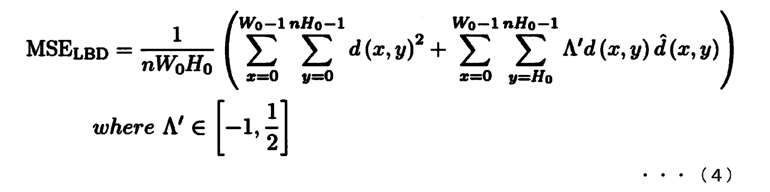
- Equation (4) Equation (4) is obtained. It is expected that the smaller the MSE LBD value shown below, the better the subjective image quality.
- the evaluation method for evaluating an image using the result of encoding up to the end has been described.
- the evaluation method according to the present invention is used as an index for determining an encoding parameter, for example, instead of the encoded image (the image obtained by decoding the encoded image), the result obtained by performing the Hadamard transform or the like is used. A certain conversion value may be used to perform a temporary evaluation with a lower calculation amount.
- the evaluation device 1 evaluates the coding quality of coded data of an image for a specific viewpoint (first viewpoint) in an input viewpoint image (multi-viewpoint image). It is a device.
- the evaluation device 1 determines the pixel value of the original image for the first viewpoint, the pixel value obtained from the encoded data of the image for the first viewpoint, and the second viewpoint different from the first viewpoint. Assessing the coding quality of the coded data of the image for the first viewpoint by associating the pixel value of the original image with the pixel value obtained from the coded data of the image for the second viewpoint.
- the coding mode selection unit 30 evaluation unit is provided.
- the evaluation device 1 can select the coding mode based on the evaluation value of the coding distortion.
- the conventional coding distortion evaluation scale does not sufficiently reflect the subjective image quality of the difference displayed on the linear blending display, whereas the evaluation apparatus 1 uses the entire image displayed on the linear blending display. That is, the subjective image quality of the input viewpoint image and the intermediate viewpoint image can be improved in a form suitable for the viewing mode and the content.
- a part or all of the evaluation device 1 in the above-described embodiment may be realized by a computer.
- the program for realizing this function may be recorded in a computer-readable recording medium, and the program recorded in this recording medium may be read by a computer system and executed.
- the “computer system” mentioned here includes an OS and hardware such as peripheral devices.
- the “computer-readable recording medium” refers to a portable medium such as a flexible disk, a magneto-optical disk, a ROM, a CD-ROM, or a storage device such as a hard disk built in a computer system.
- the "computer-readable recording medium” means to hold a program dynamically for a short time like a communication line when transmitting the program through a network such as the Internet or a communication line such as a telephone line.
- a volatile memory inside a computer system that serves as a server or a client in that case may hold a program for a certain period of time.
- the program may be for realizing a part of the functions described above, and may be a program that can realize the functions described above in combination with a program already recorded in a computer system, It may be realized by using hardware such as PLD (Programmable Logic Device) and FPGA (Field Programmable Gate Array).
Landscapes
- Engineering & Computer Science (AREA)
- Multimedia (AREA)
- Signal Processing (AREA)
- Health & Medical Sciences (AREA)
- Biomedical Technology (AREA)
- General Health & Medical Sciences (AREA)
- Compression Or Coding Systems Of Tv Signals (AREA)
- Testing, Inspecting, Measuring Of Stereoscopic Televisions And Televisions (AREA)
Abstract
多視点画像における第一の視点に対する画像の符号化データの符号化品質を評価する評価装置は、前記第一の視点に対する原画像の画素値と、前記第一の視点に係る符号化データから得られた画素値と、前記第一の視点とは異なる第二の視点に対する原画像の画素値と、前記第二の視点に係る符号化データから得られた画素値と、を関連付けることで前記第一の視点に係る符号化データの符号化品質を評価する評価部を備える。
Description
本発明は、評価装置、評価方法、及びプログラムに関する。
高臨場感を表現するためには滑らかな運動視差の表現が重要である。運動視差の表現方式としては多眼表示があるが視域の切換えが発生する。多眼表示の指向性密度を向上した超多眼表示又は高密度指向性表示では運動視差は滑らかになるものの連続的な運動視差を表現するには多くの画像数が必要となる。そこで、複数の画像をリニアブレンディングすることにより少ない画像数で連続的な運動視差を表現する表示技術が提案されている。リニアブレンディングは、隣接した2つのカメラによってそれぞれ撮像された2つの画像に対して線形補完を行うことによって、これらのカメラの中間に位置する視点(以下、「中間視点」という。)に対する画像を生成する手法である(例えば、非特許文献1)。このリニアブレンディングを用いて裸眼3D(three-dimensional;3次元)表示を実現するディスプレイを、リニアブレンディングディスプレイという(例えば、非特許文献2)。リニアブレンディングディスプレイは、視点の方向に応じて異なる光線を表示することができる。リニアブレンディングディスプレイは、カメラアレイにより撮像された多視点画像から中間視点に相当する画像を生成し、視点の位置に応じた画像を出力する。これにより、視聴者は、移動に伴って変化する視点の位置にそれぞれ対応する画像を見ることができるため、立体感を得ることができる。以下、リニアブレンディングディスプレイに入力される多視点画像のことを「入力視点画像」、入力視点画像からリニアブレンディングにより生成される画像のことを「中間視点画像」と呼ぶことにする。
ところで、非可逆圧縮方式による画像データの符号化・復号においては、原画像と復号画像との間に画素値の差(符号化歪み)が生じる。一般に、符号化歪みの歪み量が大きいと主観画質に影響を及ぼすため、歪み量及び符号量の双方を小さくするように符号化モードの選択が行われる。従来、この歪み量を表す評価指標として、原画像の画素値と復号画像の画素値との二乗誤差が用いられている。二乗誤差SEは、以下の式(1)によって表される。

ここで、W及びHは、符号化対象ブロックにおける水平方向の画素数及び垂直方向の画素数をそれぞれ表す。また、d(x,y)は、符号化対象ブロック内の座標(x,y)の画素における、原画像の画素値と復号画像の画素値との差分値である。一般的な符号化モードの選択においては、この二乗誤差SEと推定符号量とを一定の比率で足し合わせるコスト関数を最小化するように、符号化モードが選択される。
M.Date et al., "Real-time viewpoint image synthesis using strips of multi-camera images," Proc. of SPIE-IS&T, Vol.9391 939109-7, 17 March 2015.
伊達宗和他, "視覚的に等価なライトフィールド フラットパネル3Dディスプレイ,"第22回日本バーチャルリアリティ学会大会論文集, 1B4-04, 2017年9月
上述した符号化歪みの歪み量の評価では、視点ごとに独立して評価が行われる。しかしながら、リニアブレンディングディスプレイに表示される画像に対し、視点ごとに独立して歪み量の評価を行った場合、生成される中間視点画像における歪み量が正しく考慮されないことがある。この点について、以下に具体例を挙げて説明する。
図6及び図7は、リニアブレンディングによる中間視点画像における符号化歪みを説明するための図である。図6(A)及び図6(B)は、互いに隣接した視点である視点A及び視点Bに対する画像におけるそれぞれの歪み量と、視点A及び視点Bの中間視点画像における歪み量とについて、2つのケースを例示したものである。なお、中間視点とは、2つの視点の中間に位置する視点の集合に含まれる任意の視点である。図6において、黒丸は原画像の画素値を、及び白丸は復号画像の画素値を表す。また、原画像の画素値から復号画像の画素値へ伸びる矢印は両者の差分を表す。また、視点Aに対する画像の座標(x,y)における差分値をd(x,y)と表し、視点Bに対する画像の座標(x,y)における差分値をd^(x,y)と表す。
図6に示すように、視点Aにおける原画像と復号画像との差分値d(x,y)は、ケース1(図6(A))とケース2(図6(B))とにおいて等しい。また、視点Bにおける原画像と復号画像との差分値d^(x,y)は、ケース1とケース2とにおいて符号が異なるが、これらの絶対値は等しい。そのため、従来の評価方法に従って視点ごとに二乗誤差を計算した場合、ケース1とケース2とでは同じ評価値になり、選択される符号化モードも同一になる。しかしながら、以下に説明する2つの観点から、ケース1とケース2とにおける符号化歪みは互いに区別して評価されるべきである。
まず、視点Aと視点Bとの間の特定の中間視点に視点が固定されている場合において、原画像に近い画像を出力するという観点で符号化歪みの評価を考える。固定された中間視点画像は、視点Aに対する画像と視点Bに対する画像が線形にブレンディングされたものとなる。そのため、符号化歪みの歪み量は中間視点の位置に応じて変化する。図6(A)に示すように、ケース1においては、原画像の画素値と復号画像の画素値との大小関係が視点Aと視点Bとの間で逆転する。これにより、中間視点画像における符号化歪みの歪み量は、視点Aにおける歪み量及び視点Bにおける歪み量と比べて小さくなる。一方、図6(B)に示すように、ケース2においては、原画像の画素値と復号画像の画素値との大小関係が視点Aと視点Bとの間で逆転しない。これにより、中間視点画像における符号化歪みの歪み量は、視点Aにおける歪み量と視点Bにおける歪み量との中間程度の歪み量になる。したがって、ケース1とケース2とでは、ケース1のほうが中間視点画像における符号化歪みの歪み量はより小さくなる。視聴者が任意の位置からリニアブレンディングディスプレイを見る際、視聴されるのは離散的に存在する入力視点画像よりも連続的に存在する中間視点画像である場合が多い。そのため、原画像に近い画像を出力するという観点では、ケース1による符号化歪みの評価値を出力する符号化モードが優先的に選択されることが望ましい。
次に、視聴者の視点が視点Aから視点Bに向かって移動する場合において、画素値の変化を本来の意図どおりに表示させるという観点で符号化歪みの評価を考える。図7に示すように、視点Aにおける符号化歪みの歪み量と視点Bにおける符号化歪みの歪み量とが、それぞれ図6と同様の歪み量である2つのケースを考える。図7に示すように、視点Aに対する画像から視点Bに対する画像への画素値の移り変わりを考えた場合、原画像においては、ケース1及びケース2ともに画素値は増加している。一方、復号画像においては、ケース2では原画像と同様に画素値が増加しているが、ケース1では画素値が減少している。そのため、視点を移動した場合の画素値の変化が本来意図したとおりに、すなわち符号化を行わない場合と同様に表示されるという観点では、ケース2による符号化歪みの評価値を出力する符号化モードが優先的に選択されることが望ましい。なお、符号化を行わない場合と同様な表示とは、原画像を用いて中間視点の画像を生成した場合の表示とほぼ同様な表示である。
以上のことから、中間視点画像が原画像と近くなることを優先する場合にはケース1に相当する符号化モードを、視点移動時における画素値の変化が本来意図したとおりに表示されることを優先する場合にはケース2に相当する符号化モードを選択することが望ましい。なお、実際には、視聴形態やコンテンツに応じてケース1及びケース2の両者のバランスを考慮し、符号化モードが決定されるべきである。例えば映画館等のように観客の視点がある程度固定されている場合、及び視聴距離が長く移動時の視線の角度変化が小さい場合等にはケース1に相当する符号化モードが優先的に選択され、観客が常に動き回る場合、及び視聴距離が短く移動時の視線の角度変化が大きい場合等にはケース2に相当する符号化モードが優先的に選択されることが望ましい。
しかしながら、二乗誤差による符号化歪みの評価を視点ごとに独立して行う従来の評価方法では、上述したように、ケース1における符号化歪みに対する評価値とケース2における符号化歪みに対する評価値とは同一となり、区別が出来ない。そのため、入力視点画像に対し、従来の評価方法を用いた場合には、符号化時に上記ケース1またはケース2に相当する符号化モードを優先的に選択することができないため、主観画質が最大化できないという課題がある。
本発明はこのような状況を鑑みてなされたもので、リニアブレンディングディスプレイにより表示される画像全体、すなわち入力視点画像及び中間視点画像の主観画質を向上させることができる技術の提供を目的としている。
本発明の一態様は、多視点画像における第一の視点に対する画像の符号化データの符号化品質を評価する評価装置であって、前記第一の視点に対する原画像の画素値と、前記第一の視点に係る符号化データから得られた画素値と、前記第一の視点とは異なる第二の視点に対する原画像の画素値と、前記第二の視点に係る符号化データから得られた画素値と、を関連付けることで前記第一の視点に係る符号化データの符号化品質を評価する評価部を備える評価装置である。
また、本発明の一態様は、上記の評価装置であって、前記評価部は、前記第二の視点に対する原画像の画素値と、前記第二の視点に係る符号化データから得られた画素値と、を用いることにより、前記多視点画像を構成する画像にはない、前記第一の視点及び前記第二の視点とは異なる第三の視点に係る評価を前記第一の視点に係る符号化データの符号化品質の評価に反映する。
また、本発明の一態様は、上記の評価装置であって、前記第三の視点は、前記第一の視点と前記第二の視点の中間に位置する視点の集合に含まれる任意の視点であり、前記評価部は、前記第一の視点に対する原画像と前記第二の視点に対する原画像とに基づく前記第三の視点に対する画像の画素値と、前記第一の視点に係る符号化データから得られた画素値と前記第二の視点に係る符号化データから得られた画素値とに基づく前記第三の視点に対する画像の画素値と、の差分値を用いて前記第一の視点に係る符号化データの符号化品質を評価する。
また、本発明の一態様は、上記の評価装置であって、前記第三の視点は、前記第一の視点と前記第二の視点の中間に位置する視点の集合に含まれる任意の視点であり、前記評価部は、前記第一の視点に対する原画像の画素値と、前記第二の視点に対する原画像の画素値と、前記第一の視点に対する原画像と前記第二の視点に対する原画像とに基づく前記第三の視点に対する画像の画素値と、のうち少なくとも2つの画素値の変化量と、前記第一の視点に係る符号化データから得られた画素値と、前記第二の視点に係る符号化データから得られた画素値と、前記第一の視点に係る符号化データから得られた画素値と前記第二の視点に係る符号化データから得られた画素値とに基づいて得られる前記第三の視点に対する画像の画素値と、のうち少なくとも2つの画素値の変化量と、を用いて前記第一の視点に係る符号化データの符号化品質を評価する。
また、本発明の一態様は、上記の評価装置であって、前記評価部は、前記第三の視点に対する画像の画素値同士の変化量を用いて、前記第一の視点に係る符号化データの符号化品質を評価する。
また、本発明の一態様は、上記の評価装置であって、前記評価部は、以下の評価式によって計算されるSELBDの値を用いて、前記第一の視点に係る符号化データの符号化品質を評価する。

ここで、W及びHは、前記第一の視点に対する原画像における、水平方向の画素数及び垂直方向の画素数をそれぞれ表す。また、d(x,y)は、前記第一の視点に対する原画像における座標(x,y)の画素値と前記第一の視点に対する復号画像における座標(x,y)の画素値との差分値を表し、d^(x,y)は、前記第二の視点に対する原画像における座標(x,y)の画素値と前記第二の視点に対する復号画像における座標(x,y)の画素値との差分値を表す。
また、本発明の一態様は、多視点画像における第一の視点に対する画像の符号化データの符号化品質を評価する評価方法であって、前記第一の視点に対する原画像の画素値と、前記第一の視点に係る符号化データから得られた画素値と、前記第一の視点とは異なる第二の視点に対する原画像の画素値と、前記第二の視点に係る符号化データから得られた画素値と、を関連付けることで前記第一の視点に係る符号化データの符号化品質を評価する評価ステップを有する評価方法である。
また、本発明の一態様は、上記の評価装置としてコンピュータを機能させるためのプログラムである。
本発明により、リニアブレンディングディスプレイにより表示される画像全体、すなわち入力視点画像及び中間視点画像の主観画質を向上させることができる。
<実施形態>
以下、本発明の一実施形態に係る評価装置、評価方法、及びプログラムについて、図面を参照しながら説明する。以下に説明する評価装置等は、入力視点画像を符号化した際の符号化歪みを評価するものである。以下に説明する評価装置等は、符号化された画像のみではなく、符号化された画像を用いて推定された視点の符号化歪みも考慮して、符号化された画像の符号化歪みの評価を行う。この評価結果は、多視点映像そのものの評価に用いることができるほか、例えば、多視点映像を符号化する際の符号化パラメータを決定するための指標としても用いることができる。
以下、本発明の一実施形態に係る評価装置、評価方法、及びプログラムについて、図面を参照しながら説明する。以下に説明する評価装置等は、入力視点画像を符号化した際の符号化歪みを評価するものである。以下に説明する評価装置等は、符号化された画像のみではなく、符号化された画像を用いて推定された視点の符号化歪みも考慮して、符号化された画像の符号化歪みの評価を行う。この評価結果は、多視点映像そのものの評価に用いることができるほか、例えば、多視点映像を符号化する際の符号化パラメータを決定するための指標としても用いることができる。
[評価装置の構成]
図1は、本発明の一実施形態に係る評価装置1の機能構成を示すブロック図である。図1に示すように、評価装置1は、原画像記憶部10と、復号画像記憶部20と、符号化モード選択部30と、を含んで構成される。評価装置1は、例えばエンコーダの一部として実装される。
図1は、本発明の一実施形態に係る評価装置1の機能構成を示すブロック図である。図1に示すように、評価装置1は、原画像記憶部10と、復号画像記憶部20と、符号化モード選択部30と、を含んで構成される。評価装置1は、例えばエンコーダの一部として実装される。
原画像記憶部10は、符号化の対象となる原画像を格納する。復号画像記憶部20は、符号化された原画像が復号された画像である復号画像を記憶する。原画像記憶部10及び復号画像記憶部20は、例えば、フラッシュメモリ、HDD(Hard Disk Drive)、SDD(Solid State Drive)、RAM(Random Access Memory;読み書き可能なメモリ)、レジスタ等によって実現される。
符号化モード選択部30は、原画像記憶部10から、符号化対象ブロックを示す情報、及び隣接視点に対する原画像を取得する。また、符号化モード選択部30は、復号画像記憶部20から、隣接視点に対する復号画像を取得する。符号化モード選択部30は、符号化対象ブロックを示す情報、隣接視点に対する原画像、及び隣接視点に対する復号画像に基づいて、符号化歪みの歪み量(変化量)を算出する。符号化モード選択部30は、歪み量が最少となる符号化モードを選択する。符号化モード選択部30は、H.265/HEVC(High Efficiency Video Coding)で行われる符号化モードの選択と同様に、符号化モードをひとつ決定するごとにコスト(歪み量)の評価式を計算する。
符号化モード選択部30は、符号化対象ブロックに対して、選択された符号化モードによって符号化及び復号を行うことにより、符号化済みブロック及び復号済みブロックを得る。符号化モード選択部30は、歪み量が最少となる符号化モードを示す情報、及び歪み量が最少となる符号化済みブロックを外部の装置へ出力する。また、符号化モード選択部30は、歪み量が最少となる復号済みブロックを復号画像記憶部20に格納する。
[符号化モード選択部の構成]
以下、符号化モード選択部30の構成について更に詳しく説明する。
図2は、本発明の一実施形態に係る評価装置1の符号化モード選択部30の機能構成を示すブロック図である。図2に示すように、符号化モード選択部30は、符号化部31と、復号部32と、差分算出部33と、歪み量算出部34と、歪み量比較部35と、符号化モード・歪み量記憶部36と、を含んで構成される。
以下、符号化モード選択部30の構成について更に詳しく説明する。
図2は、本発明の一実施形態に係る評価装置1の符号化モード選択部30の機能構成を示すブロック図である。図2に示すように、符号化モード選択部30は、符号化部31と、復号部32と、差分算出部33と、歪み量算出部34と、歪み量比較部35と、符号化モード・歪み量記憶部36と、を含んで構成される。
符号化部31は、原画像記憶部10から、符号化対象ブロックを示す情報、及び隣接視点に対する原画像を取得する。符号化部31は、符号化モード・歪み量記憶部36に記憶された符号化モードの中から、試行する符号化モードを決定する。符号化部31は、決定された符号化モードによって符号化対象ブロックの符号化を行うことにより、符号化済みブロックを得る。符号化部31は、符号化済みブロックを復号部32へ出力する。また、符号化部31は、上記の処理を繰り返すことによって得られる、歪み量が最少となる符号化済みブロックを外部の装置へ出力する。
復号部32は、符号化部31から出力された符号化済みブロックを取得する。復号部32は、符号化済みブロックに対して復号を行うことにより、復号済みブロックを得る。復号部32は、復号済みブロックを差分算出部33へ出力する。また、符号化部31は、上記の処理を繰り返すことによって得られる、歪み量が最少となる復号済みブロックを外部の装置へ出力する。
差分算出部33は、原画像記憶部10から、符号化対象ブロックを示す情報、及び隣接視点に対する原画像を取得する。また、差分算出部33は、復号画像記憶部20から、隣接視点に対する復号画像を取得する。また、差分算出部33は、復号部32から、上記符号化対象ブロックの位置と画面上において同位置にあたる隣接視点に係る復号済みブロックを取得する。
そして、差分算出部33は、隣接視点に対する原画像における符号化ブロックの画素値と隣接視点に対する復号画像における同位置のブロックの画素値との差分値、及び隣接視点に対する原画像における符号化ブロックの画素値と復号部32から取得した復号済みブロックの画素値との差分値を画素ごとにそれぞれ算出する。差分算出部33は、算出された差分値を歪み量算出部34へ出力する。
歪み量算出部34は、差分算出部33から出力された差分値を取得する。歪み量算出部34は、取得した差分値をそれぞれ評価式に代入して計算を行うことにより、歪み量を算出する。歪み量算出部34は、評価式による計算結果の計算結果を歪み量比較部35へ出力する。
歪み量比較部35は、歪み量算出部34から出力された計算結果を取得する。歪み量比較部35は、取得した計算結果を、符号化モード・歪み量記憶部36に記憶させる。また、歪み量比較部35は、符号化モード・歪み量記憶部36から、それまでの計算結果の最小値を取得する。歪み量比較部35は、上記計算結果と、それまでの計算結果の最小値とを比較する。
歪み量比較部35は、それまでの計算結果の最小値よりも上記計算結果のほうが小さい場合、符号化モード・歪み量記憶部36に記憶されている当該最小値の値を、上記計算結果によって更新する。また、歪み量比較部35は、それまでの計算結果の最小値よりも上記計算結果のほうが小さい場合、符号化モード・歪み量記憶部36に記憶されている、歪み量が最少となる符号化モードを示す変数の値を、符号化部31によって決定された上記符号化モードを示す値によって更新する。
符号化モード・歪み量記憶部36は、それまでの計算結果の最小値、及び歪み量が最少となる符号化モードを示す変数の値を記憶する。符号化モード・歪み量記憶部36は、例えば、フラッシュメモリ、HDD、SDD、RAM、レジスタ等によって実現される。
なお、評価装置1に入力されるリニアブレンディングされた入力視点画像は、図4に示すように、複数の視点に対する画像がそれぞれサブサンプリングされた上で、縦方向に積み重ねられた画像である。なお、差分算出部33に入力される隣接視点に対する原画像及び隣接視点に対する復号画像は、画面上において符号化対象ブロックと同位置に相当する領域(原画像内及び復号画像内の部分的な画像)であってもよい。例えば図5に示すように、符号化対象ブロックが、視点Aに対する画像の画像領域ar1である場合、差分算出部33に入力される、隣接視点に対する原画像及び隣接視点に対する復号画像は、視点Bに対する画像の画像領域ar2の部分のみであってもよい。なお、符号化ブロックは、図5に示すように、座標(x,y)からなる画素の集合である。
なお、符号化対象ブロックは、入力画像内において最初に符号化される視点以外(すなわち、図4においては、視点1以外)の視点に対する画像の中から選択される必要がある。これは、以下に説明する評価手順において、符号化対象ブロックに係る評価を、当該符号化対象ブロックに対応する視点の一つ前に符号化される隣接視点に対する画像を用いて行うためである。なお、最初に符号化される視点視点に対する画像に対しては、例えば、一般的にH.265/HEVCで行われるような、二乗誤差の計算に基づく符号化モードの選択を行えばよい。
[符号化モード選択部の動作]
以下、符号化モード選択部30の動作について説明する。
図3は、本発明の一実施形態に係る評価装置1の符号化モード選択部30の動作を示すフローチャートである。ここでは、水平方向のサイズがWであり、垂直方向のサイズがHである符号化ブロックの符号化を行う場合について説明する。なお、W及びHは、例えば画素数である。
以下、符号化モード選択部30の動作について説明する。
図3は、本発明の一実施形態に係る評価装置1の符号化モード選択部30の動作を示すフローチャートである。ここでは、水平方向のサイズがWであり、垂直方向のサイズがHである符号化ブロックの符号化を行う場合について説明する。なお、W及びHは、例えば画素数である。
符号化部31は、符号化対象ブロックを示す情報、及び隣接視点に対する原画像を取得する。符号化部31は、新たに試行する符号化モードを示す変数であるPred_tmpの値を決定した後(ステップS001)、当該符号化モードによって符号化対象ブロックの符号化を行うことにより、符号化済みブロックを得る。復号部32は、符号化済みブロックに対して復号を行うことにより、復号済みブロックを得る(ステップS002)。
差分算出部33は、原画像記憶部10から、符号化対象ブロックを示す情報、及び隣接視点に対する原画像を取得する。また、差分算出部33は、復号画像記憶部20から、隣接視点に対する復号画像を取得する。また、差分算出部33は、復号部32から、符号化対象ブロックの位置と画面上において同位置にあたる隣接視点に係る復号済みブロックを取得する(ステップS003)。そして、差分算出部33は、原画像の画素値と復号画像の画素値との差分値、及び原画像の画素値と復号済みブロックの画素値との差分値を、画素ごとにそれぞれ算出する(ステップS004)。
歪み量算出部34は、差分算出部33によって算出された差分値を、評価式である以下の式(2)に代入して計算を行うことにより、歪み量を算出する(ステップS005)。

ここで、W及びHは、前記第一の視点に対する原画像における、水平方向の画素数及び垂直方向の画素数をそれぞれ表す。また、d(x,y)は、前記第一の視点に対する原画像における座標(x,y)の画素値と前記第一の視点に対する復号画像における座標(x,y)の画素値との差分値を表し、d^(x,y)は、前記第二の視点に対する原画像における座標(x,y)の画素値と前記第二の視点に対する復号画像における座標(x,y)の画素値との差分値を表す。
ここで、Λ=1とした場合には、式(2)は、原画像に近い画像を出力するという観点での符号化歪みの評価式となる。また、Λ=-2とした場合、式(2)は、視点を移動した場合の画素値の変化が本来意図したとおりに、すなわち符号化を行わない場合と同様に表示されるという観点での符号化歪みの評価式となる。なお、符号化を行わない場合と同様な表示とは、原画像を用いて中間視点の画像を生成した場合の表示とほぼ同様な表示である。
歪み量比較部35は、歪み量算出部34によって算出された計算結果を、一時変数であるcost_tmpの値として符号化モード・歪み量記憶部36に記憶させる。そして、歪み量比較部35は、cost_tmpと、それまでの式(2)の計算結果における最小値であるcost_minとを比較する(ステップS006)。
歪み量比較部35は、cost_minよりもcost_tmpのほうが小さい場合、符号化モード・歪み量記憶部36に記憶されているcost_minの値を、cost_tmpの値によって更新する。また、歪み量比較部35は、cost_minよりもcost_tmpのほうが小さい場合、符号化モード・歪み量記憶部36に記憶されている、歪み量が最少となる符号化モードを示す変数であるPred_minの値を、上記Pred_tmpの値によって更新する(ステップS007)。
符号化モード選択部30は、全ての符号化モードを試行済みであるか否かを判定する(ステップS008)。全ての符号化モードを試行済みである場合、符号化モード選択部30は、Pred_minの値を出力し(ステップS009)、図3のフローチャートに示す動作を終了する。一方、試行済みでない符号化モードがある場合、符号化モード選択部30は、試行済みでない符号化モードを用いて上記と同様の処理を繰り返す(ステップS001に戻る)。
<その他の実施形態>
なお、上述した実施形態では、リニアブレンディングディスプレイにおける画像を対象とした符号化歪みの評価方法について述べたが、式(2)におけるΛの値を負の値とした場合には、この評価方法は、一般的な多視点画像を対象とした符号化歪みの評価にも用いることができる。
なお、上述した実施形態では、リニアブレンディングディスプレイにおける画像を対象とした符号化歪みの評価方法について述べたが、式(2)におけるΛの値を負の値とした場合には、この評価方法は、一般的な多視点画像を対象とした符号化歪みの評価にも用いることができる。
一般的な多視点画像においては、画面の切り替えによる多視点表示、及び左右の目に別々の映像を出力する立体視表示において中間視点が生成されない。そのため、上記課題におけるケース1について考慮する必要がない。一方、上記課題におけるケース2は、隣接視点の符号化歪みの整合性を意味するため、主観画質に影響することが考えられる。そのため、Λの値を負の値として隣接視点の符号化歪みとの相関を考慮することによって、主観画質の向上を図ることができる。
なお、上述した実施形態では、符号化モードの選択において、二乗誤差の代替として式(2)の評価式を用いた。この他、例えば以下のように画像全体の評価値を計算することによって、画質評価を行うこともできる。まず、最初に符号化される視点に対する画像と最後に符号化されるの視点に対する画像との間における画素値の二乗誤差を計算する。次に、最初に符号化される視点に対する画像を除く画像全体に対して、式(2)の評価式を計算する。そして、これら2つの計算結果を足し合わせる。ここで、各視点に対する画像の水平方向のサイズをW0、垂直方向のサイズをH0、及び視点数をnとした場合、符号化歪みの評価式は以下の式(3)によって表される。

次に、解像度に関する依存性を無くすため、上記の式(3)の評価式をさらに画像の画素数、及び2で除算することで、MSE(Mean Squared Error;平均二乗誤差)を拡張した以下の式(4)が得られる。以下に示すMSELBDの値が小さいほど、より主観画質が良くなることが期待される。
さらに画素値の階調に関する依存性を無くすため、上記の式(4)をピークとなる信号値でスケーリングすることで、既存のPSNR(Peak Signal-to-Noise ratio;ピーク信号対雑音比)に対応する以下の式(5)が得られ、これにより以下の式(6)が得られる。以下に示すPSNRLBDの値が大きいほど、より主観画質が良くなることが期待される。


なお、上述した実施形態では、最後まで符号化を行った結果を用いて画像を評価する評価方法について述べた。しかしながら、本発明に係る評価方法を、例えば符号化パラメータを決定するための指標として用いる場合には、符号化された画像(を復号した画像)に代えて、例えばアダマール変換等を行った結果である変換値を用いて、より低演算量となる仮の評価を行うようにしてもよい。
以上説明したように、本発明の実施形態に係る評価装置1は、入力視点画像(多視点画像)における特定の視点(第一の視点)に対する画像の符号化データの符号化品質を評価する評価装置である。評価装置1は、前記第一の視点に対する原画像の画素値と、前記第一の視点に対する画像に係る符号化データから得られた画素値と、第一の視点とは異なる第二の視点に対する原画像の画素値と、前記第二の視点に対する画像に係る符号化データから得られた画素値と、を関連付けることで、前記第一の視点に対する画像に係る符号化データの符号化品質を評価する符号化モード選択部30(評価部)を備える。
上記の構成を備えることによって、本発明の実施形態に係る評価装置1は、符号化歪みの評価値に基づいた符号化モードを選択することができる。これにより、従来の符号化歪みの評価尺度では、リニアブレンディングディスプレイに表示された差異の主観画質を十分に反映していないのに対し、評価装置1は、リニアブレンディングディスプレイにより表示される画像全体、すなわち入力視点画像及び中間視点画像の主観画質を、視聴形態やコンテンツの内容に適した形で向上させることができる。
上述した実施形態における評価装置1の一部又は全部を、コンピュータで実現するようにしてもよい。その場合、この機能を実現するためのプログラムをコンピュータ読み取り可能な記録媒体に記録して、この記録媒体に記録されたプログラムをコンピュータシステムに読み込ませ、実行することによって実現してもよい。なお、ここでいう「コンピュータシステム」とは、OSや周辺機器等のハードウェアを含むものとする。また、「コンピュータ読み取り可能な記録媒体」とは、フレキシブルディスク、光磁気ディスク、ROM、CD-ROM等の可搬媒体、コンピュータシステムに内蔵されるハードディスク等の記憶装置のことをいう。さらに「コンピュータ読み取り可能な記録媒体」とは、インターネット等のネットワークや電話回線等の通信回線を介してプログラムを送信する場合の通信線のように、短時間の間、動的にプログラムを保持するもの、その場合のサーバやクライアントとなるコンピュータシステム内部の揮発性メモリのように、一定時間プログラムを保持しているものも含んでもよい。また上記プログラムは、上述した機能の一部を実現するためのものであっても良く、さらに上述した機能をコンピュータシステムにすでに記録されているプログラムとの組み合わせで実現できるものであってもよく、PLD(Programmable Logic Device)やFPGA(Field Programmable Gate Array)等のハードウェアを用いて実現されるものであってもよい。
以上、図面を参照して本発明の実施形態を説明してきたが、上記実施形態は本発明の例示に過ぎず、本発明が上記実施形態に限定されるものではないことは明らかである。したがって、本発明の技術思想及び要旨を逸脱しない範囲で構成要素の追加、省略、置換、及びその他の変更を行ってもよい。
1…評価装置、10…原画像記憶部、20…復号画像記憶部、30…符号化モード選択部、31…符号化部、32…復号部、33…差分算出部、34…歪み量算出部、35…歪み量比較部、36…符号化モード・歪み量記憶部
Claims (8)
- 多視点画像における第一の視点に対する画像の符号化データの符号化品質を評価する評価装置であって、
前記第一の視点に対する原画像の画素値と、前記第一の視点に係る符号化データから得られた画素値と、前記第一の視点とは異なる第二の視点に対する原画像の画素値と、前記第二の視点に係る符号化データから得られた画素値と、を関連付けることで前記第一の視点に係る符号化データの符号化品質を評価する評価部
を備える評価装置。 - 前記評価部は、
前記第二の視点に対する原画像の画素値と、前記第二の視点に係る符号化データから得られた画素値と、を用いることにより、前記多視点画像を構成する画像にはない、前記第一の視点及び前記第二の視点とは異なる第三の視点に係る評価を前記第一の視点に係る符号化データの符号化品質の評価に反映する
請求項1に記載の評価装置。 - 前記第三の視点は、前記第一の視点と前記第二の視点の中間に位置する視点の集合に含まれる任意の視点であり、
前記評価部は、
前記第一の視点に対する原画像と前記第二の視点に対する原画像とに基づく前記第三の視点に対する画像の画素値と、前記第一の視点に係る符号化データから得られた画素値と前記第二の視点に係る符号化データから得られた画素値とに基づく前記第三の視点に対する画像の画素値と、の差分値を用いて前記第一の視点に係る符号化データの符号化品質を評価する
請求項2に記載の評価装置。 - 前記第三の視点は、前記第一の視点と前記第二の視点の中間に位置する視点の集合に含まれる任意の視点であり、
前記評価部は、
前記第一の視点に対する原画像の画素値と、前記第二の視点に対する原画像の画素値と、前記第一の視点に対する原画像と前記第二の視点に対する原画像とに基づく前記第三の視点に対する画像の画素値と、のうち少なくとも2つの画素値の変化量と、
前記第一の視点に係る符号化データから得られた画素値と、前記第二の視点に係る符号化データから得られた画素値と、前記第一の視点に係る符号化データから得られた画素値と前記第二の視点に係る符号化データから得られた画素値とに基づいて得られる前記第三の視点に対する画像の画素値と、のうち少なくとも2つの画素値の変化量と、
を用いて前記第一の視点に係る符号化データの符号化品質を評価する
請求項2に記載の評価装置。 - 前記評価部は、
前記第三の視点に対する画像の画素値同士の変化量を用いて、前記第一の視点に係る符号化データの符号化品質を評価する
請求項4に記載の評価装置。 - 前記評価部は、
以下の評価式によって計算されるSELBDの値を用いて、前記第一の視点に係る符号化データの符号化品質を評価する
請求項3から請求項5のうちいずれか一項に記載の評価装置。

- 多視点画像における第一の視点に対する画像の符号化データの符号化品質を評価する評価方法であって、
前記第一の視点に対する原画像の画素値と、前記第一の視点に係る符号化データから得られた画素値と、前記第一の視点とは異なる第二の視点に対する原画像の画素値と、前記第二の視点に係る符号化データから得られた画素値と、を関連付けることで前記第一の視点に係る符号化データの符号化品質を評価する評価ステップ
を有する評価方法。 - 請求項1から請求項6のうちいずれか一項に記載の評価装置としてコンピュータを機能させるためのプログラム。
Priority Applications (1)
| Application Number | Priority Date | Filing Date | Title |
|---|---|---|---|
| US17/294,956 US11671624B2 (en) | 2018-11-21 | 2019-11-13 | Evaluation apparatus, evaluation method and program |
Applications Claiming Priority (2)
| Application Number | Priority Date | Filing Date | Title |
|---|---|---|---|
| JP2018218458A JP7168848B2 (ja) | 2018-11-21 | 2018-11-21 | 評価装置、評価方法、及びプログラム。 |
| JP2018-218458 | 2018-11-21 |
Publications (1)
| Publication Number | Publication Date |
|---|---|
| WO2020105520A1 true WO2020105520A1 (ja) | 2020-05-28 |
Family
ID=70774451
Family Applications (1)
| Application Number | Title | Priority Date | Filing Date |
|---|---|---|---|
| PCT/JP2019/044458 Ceased WO2020105520A1 (ja) | 2018-11-21 | 2019-11-13 | 評価装置、評価方法、及びプログラム。 |
Country Status (3)
| Country | Link |
|---|---|
| US (1) | US11671624B2 (ja) |
| JP (1) | JP7168848B2 (ja) |
| WO (1) | WO2020105520A1 (ja) |
Cited By (1)
| Publication number | Priority date | Publication date | Assignee | Title |
|---|---|---|---|---|
| CN111754493A (zh) * | 2020-06-28 | 2020-10-09 | 北京百度网讯科技有限公司 | 图像噪点强度评估方法、装置、电子设备及存储介质 |
Citations (5)
| Publication number | Priority date | Publication date | Assignee | Title |
|---|---|---|---|---|
| WO2008035665A1 (fr) * | 2006-09-20 | 2008-03-27 | Nippon Telegraph And Telephone Corporation | procédé DE CODAGE D'IMAGE, PROCÉDÉ DE DÉCODAGE, DISPOSITIF associÉ, DISPOSITIF DE DÉCODAGE D'IMAGE, programme associÉ, et support de stockage contenant le programme |
| JP2011199382A (ja) * | 2010-03-17 | 2011-10-06 | Fujifilm Corp | 画像評価装置、方法、及びプログラム |
| JP2012182785A (ja) * | 2011-02-07 | 2012-09-20 | Panasonic Corp | 映像再生装置および映像再生方法 |
| JP2013236134A (ja) * | 2012-05-02 | 2013-11-21 | Nippon Telegr & Teleph Corp <Ntt> | 3d映像品質評価装置及び方法及びプログラム |
| WO2014168121A1 (ja) * | 2013-04-11 | 2014-10-16 | 日本電信電話株式会社 | 画像符号化方法、画像復号方法、画像符号化装置、画像復号装置、画像符号化プログラム、および画像復号プログラム |
Family Cites Families (19)
| Publication number | Priority date | Publication date | Assignee | Title |
|---|---|---|---|---|
| BRPI0721077A2 (pt) * | 2006-12-28 | 2014-07-01 | Nippon Telegraph & Telephone | Método de codificação e método de decodificação de vídeo, aparelhos para os mesmos, programas para os mesmos, e meio de armazenamento o qual armazena os programas |
| JP2010157822A (ja) * | 2008-12-26 | 2010-07-15 | Victor Co Of Japan Ltd | 画像復号装置、画像符復号方法およびそのプログラム |
| RU2525850C2 (ru) * | 2009-02-12 | 2014-08-20 | Ниппон Телеграф Энд Телефон Корпорейшн | Способ кодирования многовидового изображения, способ декодирования многовидового изображения, устройство кодирования многовидового изображения, устройство декодирования многовидового изображения, компьютерно-читаемый носитель, содержащий программу кодирования многовидового изображения и компьютерно-читаемый носитель, содержащий программу декодирования многовидового изображения |
| CN101600108B (zh) * | 2009-06-26 | 2011-02-02 | 北京工业大学 | 一种多视点视频编码中的运动和视差联合估计方法 |
| JP5281632B2 (ja) * | 2010-12-06 | 2013-09-04 | 日本電信電話株式会社 | 多視点画像符号化方法,多視点画像復号方法,多視点画像符号化装置,多視点画像復号装置およびそれらのプログラム |
| CN102999911B (zh) * | 2012-11-27 | 2015-06-03 | 宁波大学 | 一种基于能量图的立体图像质量客观评价方法 |
| US10204658B2 (en) * | 2014-07-14 | 2019-02-12 | Sony Interactive Entertainment Inc. | System and method for use in playing back panorama video content |
| WO2016080354A1 (ja) * | 2014-11-17 | 2016-05-26 | 日本電信電話株式会社 | 映像品質推定装置、映像品質推定方法、および映像品質推定プログラム |
| FR3042368A1 (fr) * | 2015-10-08 | 2017-04-14 | Orange | Procede de codage et de decodage multi-vues, dispositif de codage et de decodage multi-vues et programmes d'ordinateur correspondants |
| US20170300318A1 (en) * | 2016-04-18 | 2017-10-19 | Accenture Global Solutions Limited | Identifying low-quality code |
| US11166034B2 (en) * | 2017-02-23 | 2021-11-02 | Netflix, Inc. | Comparing video encoders/decoders using shot-based encoding and a perceptual visual quality metric |
| US11006161B1 (en) * | 2017-12-11 | 2021-05-11 | Harmonic, Inc. | Assistance metadata for production of dynamic Over-The-Top (OTT) adjustable bit rate (ABR) representations using On-The-Fly (OTF) transcoding |
| KR102520626B1 (ko) * | 2018-01-22 | 2023-04-11 | 삼성전자주식회사 | 아티팩트 감소 필터를 이용한 영상 부호화 방법 및 그 장치, 영상 복호화 방법 및 그 장치 |
| US10659815B2 (en) * | 2018-03-08 | 2020-05-19 | At&T Intellectual Property I, L.P. | Method of dynamic adaptive streaming for 360-degree videos |
| US10931956B2 (en) * | 2018-04-12 | 2021-02-23 | Ostendo Technologies, Inc. | Methods for MR-DIBR disparity map merging and disparity threshold determination |
| US10440367B1 (en) * | 2018-06-04 | 2019-10-08 | Fubotv Inc. | Systems and methods for adaptively encoding video stream |
| US10990812B2 (en) * | 2018-06-20 | 2021-04-27 | Agora Lab, Inc. | Video tagging for video communications |
| US12204686B2 (en) * | 2018-06-20 | 2025-01-21 | Agora Lab, Inc. | Video tagging for video communications |
| US10735778B2 (en) * | 2018-08-23 | 2020-08-04 | At&T Intellectual Property I, L.P. | Proxy assisted panoramic video streaming at mobile edge |
-
2018
- 2018-11-21 JP JP2018218458A patent/JP7168848B2/ja active Active
-
2019
- 2019-11-13 US US17/294,956 patent/US11671624B2/en active Active
- 2019-11-13 WO PCT/JP2019/044458 patent/WO2020105520A1/ja not_active Ceased
Patent Citations (5)
| Publication number | Priority date | Publication date | Assignee | Title |
|---|---|---|---|---|
| WO2008035665A1 (fr) * | 2006-09-20 | 2008-03-27 | Nippon Telegraph And Telephone Corporation | procédé DE CODAGE D'IMAGE, PROCÉDÉ DE DÉCODAGE, DISPOSITIF associÉ, DISPOSITIF DE DÉCODAGE D'IMAGE, programme associÉ, et support de stockage contenant le programme |
| JP2011199382A (ja) * | 2010-03-17 | 2011-10-06 | Fujifilm Corp | 画像評価装置、方法、及びプログラム |
| JP2012182785A (ja) * | 2011-02-07 | 2012-09-20 | Panasonic Corp | 映像再生装置および映像再生方法 |
| JP2013236134A (ja) * | 2012-05-02 | 2013-11-21 | Nippon Telegr & Teleph Corp <Ntt> | 3d映像品質評価装置及び方法及びプログラム |
| WO2014168121A1 (ja) * | 2013-04-11 | 2014-10-16 | 日本電信電話株式会社 | 画像符号化方法、画像復号方法、画像符号化装置、画像復号装置、画像符号化プログラム、および画像復号プログラム |
Cited By (1)
| Publication number | Priority date | Publication date | Assignee | Title |
|---|---|---|---|---|
| CN111754493A (zh) * | 2020-06-28 | 2020-10-09 | 北京百度网讯科技有限公司 | 图像噪点强度评估方法、装置、电子设备及存储介质 |
Also Published As
| Publication number | Publication date |
|---|---|
| US20220021903A1 (en) | 2022-01-20 |
| JP2020088532A (ja) | 2020-06-04 |
| JP7168848B2 (ja) | 2022-11-10 |
| US11671624B2 (en) | 2023-06-06 |
Similar Documents
| Publication | Publication Date | Title |
|---|---|---|
| US20260006161A1 (en) | Image data encoding/decoding method and apparatus | |
| US20250350845A1 (en) | Image data encoding/decoding method and apparatus | |
| US10986342B2 (en) | 360-degree image encoding apparatus and method, and recording medium for performing the same | |
| US11405643B2 (en) | Sequential encoding and decoding of volumetric video | |
| CN109417642B (zh) | 用于高分辨率影像流的影像比特流生成方法和设备 | |
| US12425649B2 (en) | Image data encoding/decoding method and apparatus | |
| KR102827856B1 (ko) | 영상 신호를 처리하기 위한 방법 및 장치 | |
| JP6232076B2 (ja) | 映像符号化方法、映像復号方法、映像符号化装置、映像復号装置、映像符号化プログラム及び映像復号プログラム | |
| US20250350846A1 (en) | Image data encoding/decoding method and apparatus | |
| Merkle et al. | The effect of depth compression on multiview rendering quality | |
| KR20220093264A (ko) | 영상 데이터 부호화/복호화 방법 및 장치 | |
| KR102342870B1 (ko) | 인트라 예측 모드 기반 영상 처리 방법 및 이를 위한 장치 | |
| JP2020120322A (ja) | 距離画像符号化装置およびそのプログラム、ならびに、距離画像復号装置およびそのプログラム | |
| JP7168848B2 (ja) | 評価装置、評価方法、及びプログラム。 | |
| WO2015056712A1 (ja) | 動画像符号化方法、動画像復号方法、動画像符号化装置、動画像復号装置、動画像符号化プログラム、及び動画像復号プログラム | |
| WO2020105576A1 (ja) | 予測装置、予測方法、及びプログラム。 | |
| JP7393931B2 (ja) | 画像符号化装置およびそのプログラム、ならびに、画像復号装置およびそのプログラム | |
| WO2012128209A1 (ja) | 画像符号化装置、画像復号装置、プログラムおよび符号化データ | |
| JP6386466B2 (ja) | 映像符号化装置及び方法、及び、映像復号装置及び方法 | |
| WO2015098827A1 (ja) | 映像符号化方法、映像復号方法、映像符号化装置、映像復号装置、映像符号化プログラム及び映像復号プログラム | |
| US20260095562A1 (en) | Image data encoding/decoding method and apparatus | |
| Phi | Perceptually Optimized Plenoptic Data Representation and Coding | |
| JP7068925B2 (ja) | 予測符号化法決定装置、動画像符号化装置、及び動画像復号装置、並びにプログラム | |
| Demos | The Use of Flowfield Motion Compensation for 3-D Stereoscopic Moving Image Compression | |
| WO2012128211A1 (ja) | 画像符号化装置、画像復号装置、プログラムおよび符号化データ |
Legal Events
| Date | Code | Title | Description |
|---|---|---|---|
| 121 | Ep: the epo has been informed by wipo that ep was designated in this application |
Ref document number: 19886119 Country of ref document: EP Kind code of ref document: A1 |
|
| NENP | Non-entry into the national phase |
Ref country code: DE |
|
| 122 | Ep: pct application non-entry in european phase |
Ref document number: 19886119 Country of ref document: EP Kind code of ref document: A1 |