WO2012128209A1 - 画像符号化装置、画像復号装置、プログラムおよび符号化データ - Google Patents
画像符号化装置、画像復号装置、プログラムおよび符号化データ Download PDFInfo
- Publication number
- WO2012128209A1 WO2012128209A1 PCT/JP2012/056870 JP2012056870W WO2012128209A1 WO 2012128209 A1 WO2012128209 A1 WO 2012128209A1 JP 2012056870 W JP2012056870 W JP 2012056870W WO 2012128209 A1 WO2012128209 A1 WO 2012128209A1
- Authority
- WO
- WIPO (PCT)
- Prior art keywords
- format
- block
- image
- unit
- copy
- Prior art date
Links
Images


Classifications
-
- H—ELECTRICITY
- H04—ELECTRIC COMMUNICATION TECHNIQUE
- H04N—PICTORIAL COMMUNICATION, e.g. TELEVISION
- H04N19/00—Methods or arrangements for coding, decoding, compressing or decompressing digital video signals
- H04N19/10—Methods or arrangements for coding, decoding, compressing or decompressing digital video signals using adaptive coding
- H04N19/102—Methods or arrangements for coding, decoding, compressing or decompressing digital video signals using adaptive coding characterised by the element, parameter or selection affected or controlled by the adaptive coding
- H04N19/119—Adaptive subdivision aspects, e.g. subdivision of a picture into rectangular or non-rectangular coding blocks
-
- H—ELECTRICITY
- H04—ELECTRIC COMMUNICATION TECHNIQUE
- H04N—PICTORIAL COMMUNICATION, e.g. TELEVISION
- H04N13/00—Stereoscopic video systems; Multi-view video systems; Details thereof
- H04N13/10—Processing, recording or transmission of stereoscopic or multi-view image signals
- H04N13/106—Processing image signals
- H04N13/161—Encoding, multiplexing or demultiplexing different image signal components
-
- H—ELECTRICITY
- H04—ELECTRIC COMMUNICATION TECHNIQUE
- H04N—PICTORIAL COMMUNICATION, e.g. TELEVISION
- H04N19/00—Methods or arrangements for coding, decoding, compressing or decompressing digital video signals
- H04N19/10—Methods or arrangements for coding, decoding, compressing or decompressing digital video signals using adaptive coding
- H04N19/169—Methods or arrangements for coding, decoding, compressing or decompressing digital video signals using adaptive coding characterised by the coding unit, i.e. the structural portion or semantic portion of the video signal being the object or the subject of the adaptive coding
- H04N19/17—Methods or arrangements for coding, decoding, compressing or decompressing digital video signals using adaptive coding characterised by the coding unit, i.e. the structural portion or semantic portion of the video signal being the object or the subject of the adaptive coding the unit being an image region, e.g. an object
- H04N19/176—Methods or arrangements for coding, decoding, compressing or decompressing digital video signals using adaptive coding characterised by the coding unit, i.e. the structural portion or semantic portion of the video signal being the object or the subject of the adaptive coding the unit being an image region, e.g. an object the region being a block, e.g. a macroblock
-
- H—ELECTRICITY
- H04—ELECTRIC COMMUNICATION TECHNIQUE
- H04N—PICTORIAL COMMUNICATION, e.g. TELEVISION
- H04N19/00—Methods or arrangements for coding, decoding, compressing or decompressing digital video signals
- H04N19/50—Methods or arrangements for coding, decoding, compressing or decompressing digital video signals using predictive coding
- H04N19/597—Methods or arrangements for coding, decoding, compressing or decompressing digital video signals using predictive coding specially adapted for multi-view video sequence encoding
Definitions
- the present invention relates to an image encoding device, an image decoding device, a program, and encoded data.
- a texture image that is a general two-dimensional image that represents the subject space with the color of each subject and the background, and an image that represents the subject space with the distance from the viewpoint to each subject and the background.
- There is a method of recording in association with two types of image data hereinafter referred to as “distance image”).
- a distance image is an image that expresses a distance value (depth value) from a viewpoint to a corresponding point in a subject space for each pixel.
- This distance image can be acquired, for example, by a distance measuring device such as a depth camera installed in the vicinity of the camera that records the texture image.
- a distance image can be acquired by analyzing a plurality of texture images obtained by photographing with a multi-viewpoint camera, and many analysis methods have been proposed.
- distance values are expressed in 256 levels (8-bit luminance values) in the Moving Picture Experts Group (MPEG), which is a working group of the International Organization for Standardization / International Electrotechnical Commission (ISO / IEC).
- MPEG Moving Picture Experts Group
- ISO / IEC International Electrotechnical Commission
- the standard MPEG-C part3 is defined, and a standard distance image is an 8-bit grayscale image.
- a subject located in front is expressed as white and a subject located in the back is expressed in black.
- a single pixel value tends to appear in a wider area than the texture image. For example, even if a person wearing a fancy pattern is drawn on the texture image, the distance value of the clothes portion is almost constant in the distance image.
- the distance from the viewpoint of each pixel constituting the subject image drawn in the texture image is known from the distance image, so that the subject has the maximum depth. It can be restored as a three-dimensional shape expressed in 256 stages. Furthermore, by projecting the 3D shape onto the 2D plane geometrically, the original texture image is converted into a texture image in the subject space when the subject is photographed from another angle within a certain range from the original angle. It is possible to convert. That is, since a 3D shape can be restored when viewed from an arbitrary angle within a certain range by a set of texture images and distance images, a free viewpoint image of 3D shapes can be obtained by using multiple sets of texture images and distance images. Can be expressed with a small amount of data.
- H. As in the case of H.264, a technique for compressing and encoding video by efficiently eliminating temporal or spatial redundancy in the video is known (for example, Non-Patent Document 1).
- a technique for compressing and encoding video by efficiently eliminating temporal or spatial redundancy in the video is known (for example, Non-Patent Document 1).
- the redundancy that each video has Can be eliminated, and the data amount of each video transmitted to the decoding device can be further reduced.
- the integer precision DCT transform is an approximation of the real number precision DCT transform (ordinary DCT), and has a feature that the amount of calculation is smaller than that.
- the Hadamard transform has a smaller amount of computation than the integer precision DCT, and is used for transforming a block (DC block) generated by collecting only DC components.
- This orthogonal transform is used to calculate the correlation within the block. In the H.264 standard, it is used for a maximum of 16 ⁇ 16 pixel blocks. That is, the correlation between pixels in a 16 ⁇ 16 pixel block is used for information compression.
- the H.264 standard also employs a method called intra prediction encoding in order to further compress information.
- the pixel value of the encoding target block is predicted using an encoded pixel adjacent to the encoding target block.
- information compression is performed by orthogonally transforming the difference from the predicted value.
- the orthogonal transformation described above only uses the correlation within the block of 16 ⁇ 16 pixels at the maximum, but by using this method of predictive coding within the screen, the compression using the correlation with the adjacent pixels is performed. Can do.
- Distance video is usually used to generate a video with a different viewpoint from the one that captured the texture video after decoding, but blur and block noise are major factors that degrade the quality of the synthesized video. This is because the position / continuity of the contour portion of the subject is very important for the quality of the composite image in the distance video.
- the contour of the subject of the texture image is continuous but the contour of the corresponding distance image is discontinuous, the contour of the subject of the synthesized texture image is also discontinuous. That is, H.I.
- the H.264 standard is an extremely efficient method for encoding video consisting of natural images using an objective measure such as PSNR (Peak Signal-to-Noise Ratio) as an index. It cannot be said that it is an efficient method for special images that are used only to synthesize viewpoint images. Even when the PSNR is the same, the quality of the synthesized video is generally higher especially when the contour portion of the subject matches the texture video corresponding thereto.
- PSNR Peak Signal-to-Noise Ratio
- the present invention has been made in view of such circumstances, and an image encoding device capable of reducing the amount of encoded data of a distance image as compared with the conventional one and the encoding supplied from the image encoding device.
- An object of the present invention is to provide an image decoding apparatus that decodes a distance image from data.
- a first aspect of the present invention is a pixel group that configures a division unit that divides a distance image into rectangular blocks of a predetermined size, and an encoded block around an encoding target block divided by the division unit. Is copied based on a predetermined copy format, and the encoding approximation block approximating the encoding target block and the encoding target block divided by the dividing unit are used by using a predetermined drawing format.
- a drawing format approximating unit that accumulates depth value information of the used drawing format, a selection unit that selects one of the copy approximating unit, and the drawing format approximating unit, and the encoding target block
- a code word generation unit for transmitting a code word generated based on the format identification information of the copy format or drawing format selected for the information and the accumulated depth value information.
- the drawing format may include two depth values and define only the boundary of the depth values.
- the selection unit may select one of the copy formats, one of the drawing formats, or one combination of one copying format and one drawing format. You may choose.
- one of the two depth values may be determined from a pixel group constituting an encoded block around the encoding target block.
- the depth value determined from the pixel group constituting the encoded block around the encoding target block is determined in advance from the pixel position defined for each drawing format. Also good.
- the depth value determined from the pixel group constituting the encoded block around the encoding target block is applied to one of the two regions included in the drawing format. Whether to do this may be defined in advance for each drawing format.
- the depth values accumulated using the drawing format are approximated using all the depth values included in the encoding target block, It may be a depth value at which distortion is minimized.
- the combination method of one copy format and one drawing format is to create an approximate block based on each copy format, and among the two areas included in each drawing format, Only the area opposite to the area adopted from the surrounding pixel group may be obtained by overwriting the approximate block.
- the selection unit may select a pixel that minimizes distortion with the input block for all pixels of the encoding target block.
- the selection unit weights the distortion of the input block with respect to all the pixels of the encoding target block as it approaches the end of the block, and calculates the weighted distortion. You may make it select what minimizes.
- the selection unit weights only the bottom row and the right end column of the block with respect to the distortion of the input block with respect to all pixels of the encoding target block. You may make it select what minimizes distortion.
- the selection section includes one copy format, two copy formats, one drawing format, or one copy format. One of the combinations of one drawing format may be selected.
- the two selections from among the copy formats are accompanied by the order of copying, and after copying in the first copy format first, the second copy format May be used for the second copy type by overwriting only the pixel group in contact with the depth value different from the depth value held by each of the pixel groups used for copying.
- the depth value quantization unit may be associated with a quantization parameter used when encoding a texture image paired with the distance image.
- an analysis unit that analyzes a codeword of an encoded distance image received from an image encoding device and a holding that holds a depth value group obtained by analysis by the analysis unit
- a decoding unit that restores the distance image for each block using a predetermined copy format or a predetermined drawing format based on the identification information of the format obtained by analysis by the analysis unit and the depth group, It is an image decoding apparatus provided with.
- a computer of an image encoding apparatus is configured to divide a distance image into rectangular blocks of a predetermined size, and codes around a block to be encoded divided by the dividing unit.
- a copy approximating unit approximating the encoding target block, and the encoding target block divided by the dividing unit have a predetermined drawing format A selection that selects one of a drawing format approximating unit, a copy approximating unit, and a drawing format approximating unit for approximating the encoding target block by using and storing the depth value information of the used drawing format Means, format identification information of the copy format or drawing format selected for the encoding target block, and the accumulated depth value information
- the generated codeword is a program for functioning as a code word generating means for transmitting.
- the fourth aspect of the present invention is obtained by analyzing the computer of the image decoding apparatus by the analyzing means for analyzing the codeword of the encoded distance image received from the image encoding apparatus, and the analyzing means.
- the distance image for each block using a predetermined copying format or a predetermined drawing format based on the holding means for holding the depth value group, the identification information in the format obtained by the analysis by the analyzing means, and the depth group Is a program for functioning as decryption means for restoring.
- encoded data of a distance image is obtained by copying an encoded pixel group around a block according to a preset copy format for each block of the image. Or by approximating the block by using a drawing format prepared in advance, and selecting one format from the copy format and drawing format, and if a drawing format is selected, the depth value used for it is stored.
- the encoded data is encoded based on the selected format number and accumulated depth value information.
- an encoding device capable of reducing the code amount of encoded data of a distance image and a decoding device that decodes a distance image from encoded data supplied from the encoding device are realized. The effect that it can be obtained.
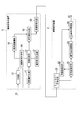
- FIG. 1 is a block diagram showing the configuration of the embodiment.
- reference numeral 1 denotes an image encoding device that inputs a distance image, performs an encoding process on the input distance image, and transmits the image via a transmission path.
- Reference numeral 2 denotes an image decoding apparatus that receives a distance image that has been subjected to encoding processing via a transmission path, decodes the distance image that has been subjected to encoding processing, and outputs a distance image.
- the image encoding device 1 includes a dividing unit 11, a process determining unit 12, a copy format determining unit 13, a drawing format determining unit 14, a depth value accumulating unit 15, and a code word generating unit 16.
- the image decoding apparatus 2 includes a codeword analysis unit 21, a depth value holding unit 22, a copy format development unit 23, and a drawing format development unit 24.
- the dividing unit 11 divides the input distance image D1 into a plurality of blocks. For example, block division is performed with 16 ⁇ 16 pixels as one block. Then, the dividing unit 11 outputs the blocks as an encoding target block to the processing determination unit in the raster scan order from the upper left block.
- the processing determination unit 12 determines which copy format is optimal for this encoding target block, which drawing format is optimal, and whether it is better to use the two in combination.
- the copy format will be explained. 2 to 9 are examples of types of copy formats.
- the 16 ⁇ 16 pixel block located at the lower right is the encoding target block B, and the other blocks are the encoded adjacent blocks.
- each grid in each block represents a pixel
- a line with an arrow represents a copy destination of the pixel.
- the encoding target block B is created by copying the pixel in the bottom row of the encoded block adjacent thereto.
- the encoding target block B all the pixel groups located in the n-th column from the left copy the n-th pixel from the left in the bottom row of the adjacent block above.
- FIG. 10 shows one extracted from the group of arrows in FIG. In this case, as shown in FIG. 11, the pixel shown in black is copied as the ninth pixel from the left of the bottom row of the adjacent block.
- Adjacent pixels are H. As in the H.264 standard, it is effective to encode a distance image by copying it and using it as it is instead of using it as a predicted value. This is due to the following reason. That is, since the distance image represents the distance to the subject, the range of the same depth value is increased to some extent. Then, except for the contour portion of the subject, the value rarely changes abruptly in units of pixels. Therefore, the probability that the adjacent blocks have the same depth value is very high. In addition, by copying adjacent pixels in this way, when the contour is continuous from the adjacent block to the encoding target block B, the continuity of the contour is maintained and various types of directions are prepared. By doing so, it is possible to deal with contours extending in various directions.
- FIG. 12 is a diagram schematically representing a distance image
- FIG. 13 is a diagram obtained by dividing FIG. 12 into blocks.
- one block represents a 16 ⁇ 16 pixel block.
- a boundary line extending horizontally across the blocks B1 to B6 is the contour of the subject.
- FIG. 14 shows an example of a drawing format.
- Each square represents a block of 16 ⁇ 16 pixels, and a line drawn therein represents a boundary of depth values.
- the drawing format P1 is a block composed of a single depth value.
- the drawing format P2 is a drawing format in which blocks are vertically divided at a ratio of 1: 3 in the horizontal direction.
- the model assumes that the number of depth values included in one block is two.
- the depth is reduced to two depth values, but the number of formats is limited, so that the compression efficiency can be increased.
- the type of this format is not limited to that shown in FIG. 14, and for example, there may be a drawing format as shown in FIG.
- the drawing format defines only the boundary of the depth value, and for the depth value, it is determined which neighboring pixel to be encoded is used for each drawing format. For example, with respect to the drawing format P2 shown in FIG. 14, the value of the pixel located on the uppermost side of the pixel column adjacent to the left side is set as the depth value of the left part, and Use the value as the depth value for the right part. Then, for each drawing format, a distortion (sum of squares of differences in depth values) with the input image is calculated.
- the drawing format determination unit 14 selects the format that best approximates the boundary line of the depth value for the encoding target block B.
- the process determination unit 12 determines the optimum usage from the drawing format determination unit 14 and the copy format determination unit 12 described above.
- the encoding target block B is (1) approximated by a copy format using an adjacent pixel group using only a copy format determination unit, and (2) approximated by a rendering format using only a drawing format determination unit. , (3) Approximate using both copy format and drawing format.
- the distortion (sum of squares of differences) between the input distance image in the pixel group included in the rightmost row of the encoding target block B and the pixel group included in the lowermost row.
- each weight is compared with other parts and calculated for each form, and the form with the smallest distortion is determined as the optimum form.
- a function that is weighted closer to the block boundary may be used. By doing so, it is possible to reduce the contour shift at the boundary with the adjacent block on the right side or the lower side of the encoding target block B, which is effective in maintaining the continuity of the contour.
- the process determination unit 12 shows information indicating which of the above approximation methods (1), (2), and (3) is encoded, and the selected drawing format when encoded by the drawing format.
- the output information is output to the codeword generation unit 16, and the information indicating the selected copy format is output to the codeword generation unit 16.
- the depth value storage unit 15 holds the input distance depth value until all the blocks included in one image are encoded by the processing determination unit 12, and one image is completely encoded. Then, the accumulated depth value group is output to the codeword generation unit 16.
- the codeword generation unit 16 assigns a codeword composed of binary values “0” or “1” to the input depth value information.
- FIG. 16 is an example of a code word generated by the code word generation unit 16 for one image.
- X1 to X5 each represent a code word consisting of binary values.
- each of X1 to X5 has a fixed length. It is assumed that the fixed length of each bit is transmitted to the decoding side in advance or before encoding or the like and is known on the decoding side.
- FIG. 17 is a diagram showing the configuration of the code word shown in FIG. X1 represents the number of transmitted depth values for this encoding target image. For example, when an image having 1024 ⁇ 768 pixels is divided into 16 ⁇ 16 pixel blocks, since the total number of blocks is 3072, the depth value is 3072 at the maximum, which can be represented by 12 bits.
- X2 is the number of depth values arranged in order by the number represented by X1. For example, when the distance depth value is represented by a value of 0 to 255, each depth value can be represented by 8 bits.
- the code word consisting of two of X3 and X4 is repeated by the number of blocks in the encoding target image.
- X3 is information indicating which of the approximation methods (1), (2), and (3) is used, and “0” when only the copy format is used (the above method (1)). When only the drawing format is used (the above-described method (2)) is “10”, and when both the copy format and the drawing format are used (the above-described method (3)) is “11”.
- X4 is identification information for identifying a copy format or a drawing format.
- Approximation method (1) or approximation method (3) is selected in X3, Represents identification information.
- approximation method 2 is selected in X3, it represents identification information in a drawing format.
- the codeword length is 3 bits for copy format representation and 4 bits for drawing format representation.
- X5 exists only when the approximation method (3) is selected in X3, and represents the identification information of the drawing format with the codeword length set to 4 bits.
- the process determination unit 12 encodes the input distance image for each block by the series of processing operations described above.
- the process determining unit 12 determines the rendering format because there is no pixel of the encoded adjacent block to be copied.
- the block B7 is output to the unit 14 to obtain the optimum drawing format P1 (see FIG. 14).
- the process determination unit 12 causes the drawing format determination unit 14 to output a single depth value (for example, value 60) constituting this block to the depth value storage unit 15.
- the depth value accumulation unit 15 accumulates this value 60 inside.
- the process determination unit 12 outputs identification information indicating that the drawing format P1 has been selected and information indicating that the value has been stored in the depth value storage unit 15 to the codeword creation unit 16.
- the codeword creation unit 16 When the codeword creation unit 16 generates a codeword according to the codeword generation rule shown in FIG. 17, a codeword with X3 “10” and X4 “0000” is generated.
- the copy format shown in FIG. 3 is selected.
- the copy format identification information shown in FIGS. 2 to 9 is assigned to 1 to 8 (“000” to “111”), respectively.
- the first X3 is 0, and X4 is 001.
- X3 is 0, and X4 is 001.
- the copy format is the format shown in FIG.
- the block other than the leftmost block has the same distortion as the copy format shown in FIG. 2 and that shown in FIG. You may choose.
- the block B1 is input to the process determination unit 12.
- the processing determination unit 12 causes the copy format determination unit 13 to calculate distortion for each format. This distortion may be distortion of all pixels in the block, or may be weighted distortion as described above. For this block, the distortion is constant in any format.
- the process determination unit 12 causes the drawing format determination unit 14 to calculate distortion for each format.
- the drawing format P13 shown in FIG. 14 has the least distortion.
- the codeword is 10 for X3 and 1100 for X4 (the identification information of the drawing format P13 is 13).
- the depth value (for example, value 90) included in the lower right corner of the block B1 is output to the depth value accumulation unit 15.
- the block after encoding at this time is a block B11 shown in FIG.
- block B2 to block B4 are sequentially input to the processing determination unit 12 in the same manner as the processing operation described above.
- Each code word at that time is similarly selected from the block B2 to the block B4 in the copy format determination unit 13 in the copy format determination unit 13, and the code word X3 is 0 and X4 is 001.
- Blocks after encoding at this time are blocks B21 to B41 shown in FIG.
- the copy format determination unit 13 selects the format shown in FIG.
- the codeword is 0 for X3 and 101 for X4.
- the block after encoding at this time is a block B51 shown in FIG.
- two types of copying formats are used together.
- code words may be defined for each combination of two copy formats.
- the distortion is approximately the same. Either may be selected as long as the distortion is the same.
- the depth value group accumulated in the depth value accumulation unit 15 and the total number thereof are output to the codeword generation unit 16, and X1 and X2 Are generated, and codewords X1 to X5 are transmitted as encoded distance images via the transmission path.
- the codeword analysis unit 21 receives the encoded distance image transmitted via the transmission path, divides the received encoded distance image into codewords X1 to X5, and transmits X1 and X2 to the depth value holding unit 22. And X3 to X5 are output to the copy format developing unit 23.
- the depth value holding unit 22 sequentially outputs the depth values to the drawing format developing unit 24 as necessary.
- the copy format developing unit 23 performs drawing on the block encoded in the copy format, and outputs the result to the drawing format developing unit 24.
- the drawing format development unit 24 performs drawing on the block encoded in the drawing format.
- X1 and X2 are output to the depth value holding unit 22.
- the head of X2 is a depth value 60 when the block B7 is encoded in the drawing format.
- the second is the depth value 90 when the block B1 is encoded in the drawing format.
- the code word 100000 for the block B 7 is input to the drawing format development unit 24.
- the drawing format developing unit 24 analyzes that X3 is 10 and X4 is 0000, selects the drawing format P1, and acquires the first depth value 60 from the depth value holding unit 22. Then, the first block is drawn in the drawing format P1 using the depth value 60.
- the X3 and X4 are output to the copy format developing unit 23.
- the copy format developing unit 23 does not perform any processing since X3 is 10, and ends the decoding of this block.
- the code word 0001 for the block on the right side of the block B7 is input to the drawing format developing unit 24.
- the drawing format developing unit 24 analyzes that X3 is 0 and X4 is 001, and outputs X3 and X4 to the copy format developing unit without performing any processing.
- the copy format developing unit uses the copy format shown in FIG. 7 to copy the pixel group included in the right end column of the block B7 in the horizontal direction. By sequentially performing such processing and decoding, the encoded distance image is decoded and the distance image is restored.
- FIG. 19 is a block diagram showing a modified configuration of the image encoding device 1 and the image decoding device 2 shown in FIG.
- the image coding apparatus 1 shown in FIG. 19 is different from the image coding apparatus 1 shown in FIG. 1 in that a depth quantization unit 17 and an entropy coding unit 18 are newly provided.
- the image decoding device 2 shown in FIG. 19 is different from the image decoding device 2 shown in FIG. 1 in that an entropy decoding unit 25 is newly provided.
- the depth quantization unit 17 quantizes the depth value of the block output from the dividing unit 11.
- the quantization step may be defined in advance.
- the quantization parameter qP used in the H.264 standard or the like may be used and associated with the value. Or you may make it match
- floor (x) is a function representing the maximum integer not exceeding x.
- the distance image can be simplified, and the subsequent encoding accuracy using the drawing format and the copying format can be improved. Further, by performing quantization in advance in this way, the number of bits allocated to X2 shown in FIG. 17 can be limited to a number of bits sufficient to express the quantization step s. It becomes compression of.
- the entropy encoder 18 further compresses the information by entropy encoding the encoded distance image generated by the codeword generator 16.
- the entropy decoding unit 25 decodes the encoded distance image that has been entropy encoded.
- arithmetic coding, lexicographic coding, adaptive arithmetic coding for adaptively updating each occurrence probability table and codebook, adaptive lexicographic coding, and the like can be applied.
- This method is a method for compressing and encoding a single distance image.
- H.264 standard can also be applied. That is, H.I. Only the I frame in the H.264 standard adopts the method of the present invention, and the B frame and the P frame are H.264.
- the H.264 standard may be used.
- the block size is described as 16 ⁇ 16 pixels.
- the block size is not limited to this and may be 8 ⁇ 8 pixels or 4 ⁇ 4 pixels.
- H.C. Like the macro block of the H.264 standard, the size may be variable in units of blocks.
- the copy format can be used without change, and the drawing format may be reduced as it is.
- the same method can be used for rectangular blocks such as 16 ⁇ 8 pixels and 8 ⁇ 16 pixels. In this case, as for the copy format, only the pixels corresponding to the rectangle may be used, and as the drawing format, a linear scale from square to those rectangles may be used.
- Determination of which of these various sizes and shapes to use is made, for example, from combinations of block shape, size, copy format or drawing format with the smallest distortion for each block of 16 ⁇ 16 pixels. This may be done by selecting the one that minimizes the distortion.
- an arrow extending from the dividing unit 11 to the process determining unit illustrated in FIG. 1 means a flow of a plurality of data output from the divided data to the process determining unit 12 after being divided into various shapes.
- an encoding device capable of reducing the code amount of encoded data of a distance image as compared with the prior art and a decoding device that decodes a distance image from encoded data supplied from the encoding device are realized. be able to.
- a program for realizing the functions of the processing units in FIGS. 1 and 19 is recorded on a computer-readable recording medium, and the program recorded on the recording medium is read into a computer system and executed to execute an image. You may perform an encoding process and an image decoding process.
- the “computer system” includes an OS and hardware such as peripheral devices.
- the “computer system” includes a WWW system having a homepage providing environment (or display environment).
- the “computer-readable recording medium” refers to a storage device such as a flexible medium, a magneto-optical disk, a portable medium such as a ROM or a CD-ROM, and a hard disk incorporated in a computer system.
- the “computer-readable recording medium” refers to a volatile memory (RAM) in a computer system that becomes a server or a client when a program is transmitted via a network such as the Internet or a communication line such as a telephone line. In addition, those holding programs for a certain period of time are also included.
- RAM volatile memory
- the program may be transmitted from a computer system storing the program in a storage device or the like to another computer system via a transmission medium or by a transmission wave in the transmission medium.
- the “transmission medium” for transmitting the program refers to a medium having a function of transmitting information, such as a network (communication network) such as the Internet or a communication line (communication line) such as a telephone line.
- the program may be for realizing a part of the functions described above. Furthermore, what can implement
Landscapes
- Engineering & Computer Science (AREA)
- Multimedia (AREA)
- Signal Processing (AREA)
- Compression Or Coding Systems Of Tv Signals (AREA)
- Compression Of Band Width Or Redundancy In Fax (AREA)
- Testing, Inspecting, Measuring Of Stereoscopic Televisions And Televisions (AREA)
Abstract
画像符号化装置は、距離画像を所定サイズの矩形のブロックに分割する分割部と、分割部により分割された符号化対象ブロック周囲の符号化済みブロックを構成する画素群を所定の複写形式に基づき複写することにより、符号化対象ブロックを近似する複写近似部と、分割部により分割された符号化対象ブロックを所定の描画形式を用いることによって符号化対象ブロックを近似するとともに、用いた描画形式の深度値の情報を蓄積する描画形式近似部と、複写近似部と、描画形式近似部のいずれかを選択する選択部と、符号化対象ブロックに対して選択した複写形式または描画形式の形式識別情報と蓄積した深度値の情報に基づいて生成した符号語を伝送する符号語生成部と、を備える。
Description
本発明は、画像符号化装置、画像復号装置、プログラムおよび符号化データに関する。
本願は、2011年3月18日に、日本に出願された特願2011-060979号に基づき優先権を主張し、その内容をここに援用する。
本願は、2011年3月18日に、日本に出願された特願2011-060979号に基づき優先権を主張し、その内容をここに援用する。
被写体の三次元形状を、正確に、且つ、効率良く記録することは重要なテーマであり、従来からさまざまな方法が提案されている。その方法の一つとして、被写空間を各被写体および背景の色で表現した一般的な二次元画像であるテクスチャ画像と、被写空間を各被写体および背景までの視点からの距離で表現した画像(以下、「距離画像」と呼ぶ)との二種類の画像データを関連付けて記録する方法がある。距離画像とは、画素ごとに、被写空間中の対応する地点までの視点からの距離値(深度値)を表現する画像である。この距離画像は、例えば、テクスチャ画像を記録するカメラ近傍に設置された、デプスカメラ等の測距装置によって取得できる。あるいは、多視点カメラの撮影によって得られる複数のテクスチャ画像を解析することによっても距離画像を取得することができ、その解析手法も数多く提案されている。
また、距離画像に関する規格として、国際標準化機構/国際電機標準会議(ISO/IEC)のワーキンググループであるMoving Picture Experts Group(MPEG)において、距離値を256段階(8ビットの輝度値)で表現する規格であるMPEG-C part3が定められており、標準的な距離画像は8ビットのグレースケール画像となる。また、視点からの距離が近いほど高い輝度値を割り当てるように規定されているため、標準的な距離画像では、手前に位置する被写体ほど白く、奥に位置する被写体ほど黒く表現される。距離画像の特徴として、テクスチャ画像と比べてより広い領域において単一の画素値が表れる傾向が強いと言える。例えば、テクスチャ画像に派手な柄の服を着ている人物が描かれていても、距離画像においては、服の部分の距離値がほぼ一定になる。
同一の被写空間を表現したテクスチャ画像と距離画像とが得られれば、テクスチャ画像に描画されている被写体像を構成する各画素の視点からの距離が距離画像から分かるため、被写体を奥行きが最大256段階で表現される三次元形状として復元することができる。さらに、三次元形状を二次元平面上に幾何的に投影することにより、元のテクスチャ画像を、元の角度から一定範囲にある別の角度から被写体を撮影した場合の被写空間のテクスチャ画像に変換することが可能である。すなわち、1組のテクスチャ画像および距離画像によって一定範囲にある任意の角度から見たときの三次元形状を復元できるため、複数組のテクスチャ画像および距離画像を用いることにより三次元形状の自由視点画像を少ないデータ量で表すことが可能である。
ところで、動画圧縮規格であるH.264のように、映像が内部に持つ時間的あるいは空間的な冗長性を効率良く排除することにより、映像を圧縮符号化する技術が知られている(例えば、非特許文献1)。この技術を用いた符号化装置により、テクスチャ映像(テクスチャ画像を各フレームとする映像)と距離映像(距離画像を各フレームとする映像)との各映像を符号化すると、各映像が有する冗長性を排除することが可能となり、復号装置に伝送される各映像のデータ量をさらに削減することができる。
このH.264規格では、画像の変換方式に、整数精度DCT変換と、アダマール変換との、2つの変換方式が採用されている。これらはともに、直交変換方式である。整数精度DCT変換は、実数精度DCT変換(通常のDCT)の近似であり、それと比べて演算量が少ないことを特徴とする。アダマール変換は、整数精度DCTよりもさらに演算量が少なく、直流成分だけを集めて生成したブロック(DCブロック)の変換に用いられる。
この直交変換は、ブロック内の相関を算出することに用いられるが、H.264規格では、最大で16×16の画素ブロックに対して用いる。すなわち、16×16の画素ブロック内の画素間の相関は情報圧縮に利用される。これらの方式は、自然画の圧縮において、適切なビットレートの範囲内では極めて効率的に情報を圧縮できるが、極端にビットレートが低くなると、画像が全体的にぼやけ、ブロックノイズが現れるという特徴を有している。
この直交変換は、ブロック内の相関を算出することに用いられるが、H.264規格では、最大で16×16の画素ブロックに対して用いる。すなわち、16×16の画素ブロック内の画素間の相関は情報圧縮に利用される。これらの方式は、自然画の圧縮において、適切なビットレートの範囲内では極めて効率的に情報を圧縮できるが、極端にビットレートが低くなると、画像が全体的にぼやけ、ブロックノイズが現れるという特徴を有している。
また、H.264規格は、より情報を圧縮するために、画面内予測符号化という方式も採用している。これは、符号化対象ブロックに隣接する符号化済み画素などを使用して、符号化対象ブロックの画素値を予測するものである。符号化対象ブロックでは、その予測値との差分を直交変換することによって情報圧縮を行う。上述の直交変換は最大で16×16画素のブロック内の相関を利用するに留まったが、この画面内予測符号化という方式を併用することで、隣接画素との相関も利用した圧縮を行うことができる。
「ITU-T 勧告 H.264」,International Telecommunication Union - Telecommunication Standardization Sector,2009年3月
しかしながら、H.264規格で規格されている圧縮符号化技術を距離映像に適応したとき、極端にビットレートが低い環境下において、上述したように、ぼやけやブロックノイズが現れる。これは、距離映像の符号化のビットレートを低下させていくと、整数精度DCT変換やアダマール変換などの直交変換した変換係数に割り当てるビット数が少なくなっていくことにより量子化歪みが増大し、ブロック内の全ての画素が直流成分の値のみとなってしまうためである。
距離映像は通常、復号後に、テクスチャ映像を撮影した視点とは別の視点の映像を生成するために用いられるが、その際、ぼやけやブロックノイズは合成映像の品質を劣化させる大きな要因となる。その理由は、距離映像において、被写体の輪郭部分の位置・連続性が、合成画像の品質に対して非常に重要であるからである。テクスチャ画像の被写体の輪郭が連続であるにも関わらず、それに対応する距離画像の輪郭が不連続である場合、合成されたテクスチャ画像の被写体の輪郭も不連続となってしまう。すなわち、H.264規格は自然画から成る映像を、PSNR(Peak Signal-to-Noise Ratio)などの客観的尺度を指標とし、符号化するために極めて効率的な方式であるが、距離映像のように、任意視点の映像を合成するためだけに用いられる特殊な映像に対しては、効率的な方式であるとは言えない。同じPSNRでも、特に被写体の輪郭部分が、それに対応するテクスチャ映像と一致している方が、合成映像の品質が一般的に高くなる。
本発明は、このような事情に鑑みてなされたもので、距離画像の符号化データの符号量を従来よりも削減することができる画像符号化装置およびこの画像符号化装置から供給された符号化データから距離画像を復号する画像復号装置を提供することを目的とする。
(1) 本発明の第1の態様は、距離画像を所定サイズの矩形のブロックに分割する分割部と、前記分割部により分割された符号化対象ブロック周囲の符号化済みブロックを構成する画素群を所定の複写形式に基づき複写することにより、前記符号化対象ブロックを近似する複写近似部と、前記分割部により分割された符号化対象ブロックを所定の描画形式を用いることによって前記符号化対象ブロックを近似するとともに、用いた前記描画形式の深度値の情報を蓄積する描画形式近似部と、前記複写近似部と、前記描画形式近似部のいずれかを選択する選択部と、前記符号化対象ブロックに対して選択した複写形式または描画形式の形式識別情報と蓄積した前記深度値の情報に基づいて生成した符号語を伝送する符号語生成部と、を備える画像符号化装置である。
(2) なお、本発明の第1の態様において、前記分割部により分割されたブロックの深度値を量子化する深度量子化部をさらに備えてもよい。
(3) なお、本発明の第1の態様において、前記描画形式は、2つの深度値を含み、深度値の境界のみを規定してもよい。
(4) なお、本発明の第1の態様において、前記選択部は、複写形式の中から1つ、あるいは描画形式の中から1つ、あるいは複写形式1つと描画形式1つの組み合わせを1つのいずれかを選択してもよい。
(5) なお、本発明の第1の態様において、前記2つのうち1つの深度値を、符号化対象ブロック周囲の符号化済みブロックを構成する画素群から決定してもよい。
(6) なお、本発明の第1の態様において、前記符号化対象ブロック周囲の符号化済みブロックを構成する画素群から決定する深度値は、予め描画形式ごとに規定する画素位置から決定してもよい。
(7) なお、本発明の第1の態様において、前記符号化対象ブロック周囲の符号化済みブロックを構成する画素群から決定する深度値を、描画形式に含まれる2つの領域のいずれかに適用するかについて、各描画形式ごとに予め規定してもよい。
(8) なお、本発明の第1の態様において、前記描画形式に用いて蓄積される深度値は、符号化対象ブロックに含まれる全ての深度値を用いて近似したときに、入力ブロックとの歪みが最も小さくなる深度値としてもよい。
(9) なお、本発明の第1の態様において、複写形式1つと描画形式1つの組み合わせ方法は、各複写形式に基づいて近似ブロックを作成し、各描画形式に含まれる2つの領域のうち、周囲の画素群から採用する方の領域とは逆の領域のみを前記近似ブロックに上書きすることによって得るようにしてもよい。
(10) なお、本発明の第1の態様において、前記選択部は、符号化対象ブロックの全画素に対し、入力ブロックとの歪みを最小とするものを選択するようにしてもよい。
(11) なお、本発明の第1の態様において、前記選択部は、符号化対象ブロックの全画素に対し、入力ブロックとの歪みを、ブロックの端に近付くほど重み付けし、その重み付けした歪みを最小とするものを選択するようにしてもよい。
(12) なお、本発明の第1の態様において、前記選択部は、符号化対象ブロックの全画素に対し、入力ブロックとの歪みを、ブロックの最下行および右端列のみ重み付けし、その重み付けした歪みを最小少とするものを選択するようにしてもよい。
(13) なお、本発明の第1の態様において、前記選択部は、複写形式の中から1つ、あるいは複写形式の中から2つ、あるいは描画形式の中から1つ、あるいは複写形式1つと描画形式1つの組み合わせを1つ、のいずれかを選択するようにしてもよい。
(14) なお、本発明の第1の態様において、前記複写形式の中からの2つの選択は、その複写の順序を伴い、先に1つめの複写形式で複写した後、2つめの複写形式を、複写に用いる画素群のうち、それぞれが保持する深度値とは異なる深度値と接している画素群のみを、2つめの複写形式に対して用い、上書きするようにしてもよい。
(15) なお、本発明の第1の態様において、前記深度値量子化部は、前記距離画像と対をなすテクスチャ画像の符号化の際に用いる量子化パラメータと対応づけられるようにしてもよい。
(16) 本発明の第2の態様は、画像符号化装置から受信した符号化距離画像の符号語を解析する解析部と、前記解析部により解析して得られた深度値群を保持する保持部と、前記解析部により解析して得られた形式の識別情報と、前記深度群に基づき、所定の複写形式または所定の描画形式を用いてブロック毎に前記距離画像を復元する復号部と、を備える画像復号装置である。
(17) 本発明の第3の態様は、画像符号化装置のコンピュータを、距離画像を所定サイズの矩形のブロックに分割する分割手段と、前記分割手段により分割された符号化対象ブロック周囲の符号化済みブロックを構成する画素群を所定の複写形式に基づき複写することにより、前記符号化対象ブロックを近似する複写近似手段と、前記分割手段により分割された符号化対象ブロックを所定の描画形式を用いることによって前記符号化対象ブロックを近似するとともに、用いた前記描画形式の深度値の情報を蓄積する描画形式近似手段と、前記複写近似手段と、前記描画形式近似手段のいずれかを選択する選択手段と、前記符号化対象ブロックに対して選択した複写形式または描画形式の形式識別情報と蓄積した前記深度値の情報に基づいて生成した符号語を伝送する符号語生成手段として機能させるためのプログラムである。
(18) 本発明の第4の態様は、画像復号装置のコンピュータを、画像符号化装置から受信した符号化距離画像の符号語を解析する解析手段と、前記解析手段により解析して得られた深度値群を保持する保持手段と、前記解析手段により解析して得られた形式の識別情報と、前記深度群に基づき、所定の複写形式または所定の描画形式を用いてブロック毎に前記距離画像を復元する復号手段として機能させるためのプログラムである。
(19) 本発明の第5の態様は、距離画像の符号化データであって、画像の各ブロックに対し、ブロック周囲の符号化済み画素群を予め設定した複写形式に従って複写することによりそのブロックを近似し、あるいは予め用意した描画形式を用いることによってそのブロックを近似し、これら複写形式と描画形式から1つの形式を選択し、描画形式を選択した場合には、それに用いた深度値を蓄積し、選択した形式の番号および蓄積した深度値の情報に基づいて符号化した符号化データである。
本発明によれば、距離画像の符号化データの符号量を従来よりも削減することができる符号化装置およびこの符号化装置から供給された符号化データから距離画像を復号する復号装置を実現することができるという効果が得られる。
以下、図面を参照して、本発明の一実施形態による画像符号化装置および画像復号装置を説明する。図1は同実施形態の構成を示すブロック図である。この図において、符号1は、距離画像を入力し、入力した距離画像に符号化処理を施して伝送路を介して伝送を行う画像符号化装置である。符号2は、伝送路を介して符号化処理が施された距離画像を受信し、符号化処理が施された距離画像を復号して距離画像を出力する画像復号装置である。画像符号化装置1は、分割部11、処理判定部12、複写形式判定部13、描画形式判定部14、深度値蓄積部15及び符号語生成部16から構成される。画像復号装置2は、符号語解析部21、深度値保持部22、複写形式展開部23及び描画形式展開部24とから構成する。
始めに、図1に示す画像符号装置1の処理動作を説明する。距離画像が入力されると、分割部11は、入力した距離画像D1を複数のブロックに分割する。例えば16×16画素を1つのブロックとしてブロック分割を行う。そして、分割部11は、ラスタスキャン順に、左上のブロックから順に、処理判定部に対して符号化対象ブロックとして出力する。処理判定部12は、この符号化対象ブロックに対し、どの複写形式が最適か、あるいは、どの描画形式が最適か、そして、それら2つを併用する方がよいかを判定する。
ここで、複写形式について説明する。図2~図9は、複写形式の種類の一例である。図2~図9において、右下に位置する16×16画素のブロックが符号化対象ブロックBであり、それ以外が符号化済みの隣接ブロックである。図2~図9において、各ブロック内の方眼一つ一つは画素を表現しており、矢印付きの線は、画素の複写先を表現している。例えば、図2において、符号化対象ブロックBは、その上に隣接する符号化済みブロックの最下行の画素を複写して作成する。具体的には、符号化対象ブロックBにおいて、左からn列目に位置する画素群は全て、上に隣接するブロックの最下行の左からn番目の画素を複写する。その他の図においても同様である。矢印の意味をさらに説明すると、例えば図8の矢印群のうちの一つを抜き出して示したものが図10である。この場合、図11に示すように黒く塗り潰して示した画素が、上に隣接するブロックの最下行左から9番目の画素を複写するということになる。
隣接画素をH.264規格のように、予測値として利用するのではなく、このように複写してそのまま利用することは、距離画像の符号化においては有効である。これは以下の理由による。すなわち、距離画像は被写体との距離を表しているため、同じ深度値の一まとまりの範囲は、ある程度大きくなる。そして、被写体の輪郭部分以外では、値が画素単位で急激に変化することは稀である。したがって、隣接ブロック同士で、同じ深度値を持つ確率が非常に高いからである。また、このように隣接画素を複写することによって、その隣接ブロックから符号化対象ブロックBに亘って輪郭が連続している場合、その輪郭の連続性が保たれ、なおかつさまざまな方向の形式を用意しておくことにより、さまざまな方向に伸びる輪郭に対応することができる。
図12は距離画像を模式的に表現した図であり、図13は、図12をブロックに分割した図である。図13において、1つのブロックは、16×16画素のブロックを表している。例えば、ブロックB1~B6に亘って水平に伸びている境界線が、被写体の輪郭である。ブロックB2~B4のブロックがそれぞれ符号化対象ブロックBの時、図3に表される複写形式を選択して適用すれば、符号化対象ブロックBを非常に良く近似できることは明らかである。
さらに、図13に示すブロックB6のように、上側からと左側からとの両方から、輪郭が繋がっている場合などに対し、複写形式を、その順番とともに2種類選択してもよい。
まず最初に、図3に示す複写形式によって複写を行った後、図2に示す複写形式によって複写を行い、既に同じ深度値で複写された列以外の列を上書きする、というルールを適用すれば、符号化対象ブロックBを非常に良く近似できることは明らかである。
まず最初に、図3に示す複写形式によって複写を行った後、図2に示す複写形式によって複写を行い、既に同じ深度値で複写された列以外の列を上書きする、というルールを適用すれば、符号化対象ブロックBを非常に良く近似できることは明らかである。
次に、描画形式判定部14について説明する。図14は、描画形式の一例であり、各正方形は、それぞれ16×16画素のブロックを表しており、その中にひかれた線は、深度値の境界を表している。描画形式P1は単一の深度値からなるブロックである。描画形式P2は、ブロックを水平方向に1:3の割合で垂直に区切った描画形式である。図14に示す例では、一つのブロックに含まれる深度値の数は2であるという仮定をしたモデルとなっている。これにより、3つ以上の異なる深度値が一つのブロックに含まれる場合、2つの深度値に縮退してしまうことにはなるが、形式の数が限られるため、圧縮効率を高めることが可能となる。他の形式についても同様である。この形式の種類については、図14に示したものに限らず、例えば図15に示すような描画形式があってもよい。
描画形式は、深度値の境界のみ規定し、深度値については、描画形式ごとに符号化済みのどの隣接画素を使用するかを決めておく。例えば、図14に示す描画形式P2については、左側に隣接する画素列の最も上側に位置する画素の値を左側の部分の深度値として、上側に隣接する画素行の最も右側に位置する画素の値を右側の部分の深度値として、それぞれ使用する。そして、各描画形式毎に、入力画像との歪み(深度値の差分の二乗和)を算出する。
しかし、これだけでは、符号化済みの隣接ブロックには含まれない深度値が符号化対象ブロックBに含まれる場合には、精度よく近似することはできないため、符号化対象ブロックBに含まれる深度値の中で、先の計算によっては使用されなかったその他の深度値がある場合、それぞれを使用して同じように、歪みを算出する。このように、隣接ブロックには含まれない深度値を使用した場合、その深度値を深度値蓄積部15に出力する。以上のように、描画形式判定部14では、符号化対象ブロックBに対し、最もよく深度値の境界線を近似する形式を選択する。
処理判定部12では、前述した描画形式判定部14と複写形式判定部12とから最適な使用方法を判定する。具体的には、符号化対象ブロックBを、(1)複写形式判定部のみを使用し、隣接画素群による複写形式で近似する、(2)描画形式判定部のみ使用し、描画形式で近似する、(3)複写形式と描画形式の両方を使用して近似する、のいずれかを選択する。
ここで、(3)描画形式と複写形式の両方を使用して近似する方法について説明する。
この場合、図2~図9に示した複写形式それぞれに対し、図14に示した描画形式を総当たりに組み合わせ、描画形式に含まれる2つの領域のうち、周囲の画素群から採用しない方の領域のみを上書きして符号化対象ブロックBを作成する。そして、それぞれについて、符号化対象ブロックB内全画素の、入力画像に対する歪みを計算する。最も歪みの少ない組み合わせが最適な組み合わせとなる。
この場合、図2~図9に示した複写形式それぞれに対し、図14に示した描画形式を総当たりに組み合わせ、描画形式に含まれる2つの領域のうち、周囲の画素群から採用しない方の領域のみを上書きして符号化対象ブロックBを作成する。そして、それぞれについて、符号化対象ブロックB内全画素の、入力画像に対する歪みを計算する。最も歪みの少ない組み合わせが最適な組み合わせとなる。
次に、前述の近似方法(1)、(2)、(3)のいずれを選択するかについて説明する。まず、符号化対象ブロックBの全画素に対する歪みを共通の基準とし、前述の近似方法(1)、(2)、(3)のそれぞれについて、その歪みを計算し、最も歪みの少ないものを選択するといった方法が考えられる。しかし、本発明の方法は、符号化済みブロックは、その後のブロックに伝播していくという特徴を有するため、ブロックの境界、特にその後に符号化対象となるブロックとの境界となる、右端列あるいは最下行に位置する画素についての歪みを少なくすることが重要となる。したがって、どの複写形式が最適かの判定については、符号化対象ブロックBの右端の行に含まれる画素群と、最下行に含まれる画素群における、入力距離画像との歪み(差分の二乗和)に対し、他の部分と比べ重み付けした上で、各形式について算出し、最も歪みが小さくなる形式を最適な形式とする。あるいは、ブロックの境界に近いほど重み付けされるような関数を用いるなどしてもよい。このようにすることにより、符号化対象ブロックBの右側や下側の隣接ブロックとの境界における輪郭のずれを少なくすることができるため、輪郭の連続性保持に有効である。
ところで、画像内の最上行に位置するブロックについては、上側の隣接ブロックが存在しないため、図3、図9の2種類の形式と、図5、図6、図7の3種類の形式の、合計5種類の形式について計算を行う。図5~7については、上側の隣接ブロックの画素群も参照しているが、符号化対象ブロックBが画像内の最上行に位置している場合は、上側の隣接ブロックの画素群の代わりに、左側の隣接ブロックの画素群のうち、上端の画素を複写するものとする。同様に、画像内の左端列に位置するブロックについては、左側の隣接ブロックが存在しないため、図2、図4、図8の3種類の形式に加え、図5~図7の3種類の、合計6種類の形式について計算を行う。先ほどと同様、参照できない画素については、上側の隣接画素群の左端の画素を用いる。そのほか、画像内の右端列に位置するブロックについては、図4と図8の形式について、上側の隣接画素群の右端の画素を用いる。ここで、上端左端のブロックについては符号化済みの隣接ブロックが存在しないため、複写形式は採用しない。
次に、処理判定部12は、前述の近似方法(1)、(2)、(3)のいずれによって符号化したかを示す情報ならびに、描画形式により符号化した場合は選択した描画形式を示す情報、深度値蓄積部15に深度値を出力した場合は出力したという情報、また、複写形式により符号化した場合は選択した複写形式を示す情報を符号語生成部16に対して出力する。
深度値蓄積部15では、一枚の画像に含まれる全てのブロックが処理判定部12によって符号化されるまで、入力された距離深度値を保持しておき、一枚の画像が符号化され終わると、蓄積した深度値群を符号語生成部16に対して出力する。符号語生成部16では、入力された深度値の情報に対し、「0」か「1」の二値で構成する符号語を割り当てる。図16は、一枚の画像に対し符号語生成部16が生成する符号語の一例である。図16において、X1~X5はそれぞれ二値からなる符号語を表している。ここでは、X1~X5のそれぞれは、固定長であるとする。そして、それぞれが何ビットの固定長であるかについては、予め、あるいは、符号化の前などに復号側に伝送され、復号側で既知であるとする。図17は、図16に示す符号語の構成を示す図である。X1は、この符号化対象画像に関し、伝送される深度値の数を表す。例えば1024×768画素を有する画像を16×16画素のブロックに分割する場合、総ブロック数は3072個であるから、深度値は最大でも3072個となるため、それは12ビットで表すことができる。
X2は、X1で表される個数だけ、深度値を順に並べたものである。例えば、距離深度値が0~255の値で表されている場合、それぞれの深度値は、8ビットで表すことができる。次に、符号化対象画像内のブロック数だけ、X3とX4との2つからなる符号語を繰り返す。X3は、前述の近似方法(1)、(2)、(3)のいずれによって符号化したかを示す情報であり、複写形式のみを使用した場合(前述の方法(1))は「0」、描画形式のみを使用した場合(前述の方法(2))は「10」、複写形式と描画形式の両方を使用した場合(前述の方法(3))は「11」となる。
X4は、複写形式あるいは描画形式を識別する識別情報である。ここでは、複写形式を図2~図9の8通り、描画形式を図14に示した13通りとし、X3にて近似方法(1)または近似方法(3)が選択されたときには、複写形式の識別情報を表し、また、X3にて近似方法2が選択されたときには、描画形式の識別情報を表す。符号語長は複写形式表現には3ビット、描画形式表現には4ビットである。X5は、X3にて近似方法(3)が選択された場合に限り存在し、符号語長を同じく4ビットとして、描画形式の識別情報を表す。
以上説明した一連の処理動作によって、処理判定部12が、入力距離画像を、ブロック毎に符号化する動作を、図13を参照して説明する。まず、ブロックB7のブロックが処理判定部12に分割部11から入力されると、このブロックには複写の対象となる符号化済み隣接ブロックの画素が存在しないので、処理判定部12は描画形式判定部14にこのブロックB7を出力し、最適な描画形式P1(図14参照)を得る。このとき、参照する深度値は存在しないので、処理判定部12は描画形式判定部14に対し、このブロックを構成する単一の深度値(例えば値60)を深度値蓄積部15に出力させる。深度値蓄積部15は、この値60を内部に蓄積する。また、処理判定部12は、描画形式P1を選択したという識別情報と、深度値蓄積部15に値を蓄積したことを示す情報を、符号語作成部16に対して出力する。符号語作成部16が、図17に示す符号語生成規則にしたがって符号語を生成すると、X3が「10」、X4が「0000」という符号語が生成されることになる。
次に、その右隣のブロックが処理判定部12に入力されると、図17に示す符号語の割り当てが行われているとすると、複写形式を使用することが、割り当てるビット数を少なく抑えられるため、図3に示す複写形式を選択する。ここでは、図2~図9に表す複写形式の識別情報はそれぞれ1~8(「000」~「111」)に割り当てられているとする。この場合、図17に示すように、最初のX3は0、X4は001となる。さらに右隣のブロックについても、これと同様の処理となるので、X3は0、X4は001となる。これが、ブロックB1の手前(図13参照)まで繰り返される。ただし、2、3行目それぞれ左端のブロックについては、複写形式が図2で示される形式になるため、符号語X4は000となる。また、2、3行目に含まれるブロックのうち、左端のブロック以外のブロックについては、複写形式が図2で示されるものと、図3で示されるものと、歪みは等しくなるため、いずれを選択してもよい。
次に、ブロックB1が処理判定部12に入力される。処理判定部12は、複写形式判定部13において各形式に対して歪みを計算させる。この歪みとは、ブロック内全画素の歪みでもよいし、上述したように、重み付けした歪みでもよい。このブロックの場合、どの形式においても歪みは一定となる。次に、処理判定部12は、描画形式判定部14において、各形式に対して歪みを計算させる。このとき、図14に示す描画形式P13の形式が最も歪みの少ないものとなる。符号語は、X3が10、X4が1100となる(描画形式P13の識別情報を13とした)。そして、ブロックB1の右下隅に含まれる深度値(例えば値90)を深度値蓄積部15に対して出力する。このときの符号化後のブロックは、図18に示すブロックB11のようになる。
次に、ブロックB2~ブロックB4が順に、前述した処理動作と同様に、処理判定部12に入力される。その時の各符号語は、ブロックB2~ブロックB4にかけて、同様に、複写形式判定部13において図7に示す複写形式を選択し、符号語はX3が0、X4が001となる。このときの符号化後のブロックは、図18に示すブロックB21~ブロックB41のようになる。
次に、ブロックB5のブロックについて、複写形式判定部13において、図7に示した形式が選択される。符号語はX3が0、X4が101となる。このときの符号化後のブロックは図18に示すブロックB51のようになる。ブロックB6のような入力ブロックに対しては、前述したように、2種類の複写形式を併用する。図17に示す符号語生成規則のX4にはそのような場合の符号語を定義していないが、例えば1001以降に、2つの複写形式の各組み合わせについて、符号語を定義すればよい。また、このブロックの場合、複写形式(図7)と描画形式(図14の描画形式P3)とを組み合わせても、歪みは同程度となる。歪みが同じであればどちらを選択してもよい。
このようにして、符号化処理を行い、一枚の画像について処理が終了した後、深度値蓄積部15に蓄積された深度値群とその総数が符号語生成部16に出力され、X1とX2が生成されて、符号語X1~X5が符号化距離画像として伝送路を介して伝送されることになる。
次に、図1に示す画像復号装置2の処理動作について説明する。符号語解析部21は、伝送路を介して伝送された符号化距離画像を受信し、受信した符号化距離画像を符号語X1~X5に分割し、X1、X2を深度値保持部22に対して出力し、X3~X5を複写形式展開部23に出力する。深度値保持部22は、必要に応じて、順に、深度値を描画形式展開部24に出力する。複写形式展開部23は、複写形式で符号化されたブロックに対して描画を行い、その結果を描画形式展開部24に出力する。描画形式展開部24は、描画形式で符号化されたブロックに対して描画を行う。このような処理によって、符号化側で符号化した入力距離画像を復号し、距離画像D2を出力する。
図13を参照して前述した具体例に沿って説明する。まず、X1とX2については、深度値保持部22に出力する。このとき、X2の先頭は、ブロックB7を描画形式で符号化したときの深度値60である。同様に、2番目は、ブロックB1を描画形式で符号化したときの深度値90である。
次に、ブロックB7に対する符号語100000が描画形式展開部24に入力される。
描画形式展開部24はX3が10、X4が0000であると解析し、描画形式P1を選択するとともに、深度値保持部22から先頭の深度値60を取得する。そして、深度値60を用いて描画形式P1の形式で、最初のブロックを描画する。また、そのX3とX4を複写形式展開部23に出力する。複写形式展開部23は、X3が10であることから何も処理を行わず、このブロックの復号を終了する。
描画形式展開部24はX3が10、X4が0000であると解析し、描画形式P1を選択するとともに、深度値保持部22から先頭の深度値60を取得する。そして、深度値60を用いて描画形式P1の形式で、最初のブロックを描画する。また、そのX3とX4を複写形式展開部23に出力する。複写形式展開部23は、X3が10であることから何も処理を行わず、このブロックの復号を終了する。
次に、ブロックB7の右隣のブロックに対する符号語0001が描画形式展開部24に入力される。描画形式展開部24はX3が0、X4が001であると解析し、何も処理を行わず、X3、X4を複写形式展開部に出力する。複写形式展開部は、図7の複写形式を用い、ブロックB7の右端列に含まれる画素群を水平方向に複写する。このような処理を順次行い、復号することにより符号化距離画像が復号されて距離画像が復元されることになる。
次に、図19を参照して、図1に示す画像符号化装置1と画像復号装置2の変形例を説明する。図19は、図1に示す画像符号化装置1と画像復号装置2を変形した構成を示すブロック図である。図19に示す画像符号化装置1が図1に示す画像符号化装置1と異なる点は、新たに深度量子化部17とエントロピー符号化部18を設けた点である。また、図19に示す画像復号装置2が図1に示す画像復号装置2と異なる点は、エントロピー復号部25を新たに設けた点である。
深度量子化部17は、分割部11から出力するブロックの深度値を量子化する。量子化ステップについては、予め規定してもよいし、例えばH.264規格などで用いられている量子化パラメータqPを用い、その値に対応づけてもよい。あるいは、この距離画像と対応するテクスチャ画像の符号化の際に用いるqPの値と対応づけてもよい。量子化パラメータqPとの対応づけは、例えば量子化パラメータqPの最大値51のときの量子化ステップを決め(例えば16=2の4乗)、それを基に各qPに対する量子化ステップを決めるようにしてもよい。この場合量子化ステップsは、
s=24+floor(51-qP/6)
と表すことができる。ここでfloor(x)はxを越えない最大の整数を表す関数である。
s=24+floor(51-qP/6)
と表すことができる。ここでfloor(x)はxを越えない最大の整数を表す関数である。
このように、先に深度値を適切に量子化しておくことによって、距離画像が単純化され、その後の、描画形式と複写形式を用いた符号化の精度を向上させることができる。さらに、このように事前に量子化を行っておくことによって、図17に示すX2に割り当てるビット数を、その量子化ステップsを表現するのに十分なビット数に制限することができ、さらなる情報の圧縮となる。
エントロピー符号化部18は、符号語生成部16によって生成した符号化距離画像を、エントロピー符号化することによって情報をさらに圧縮する。エントロピー復号部25は、エントロピー符号化された符号化距離画像を復号する。この方式としては、算術符号化や辞書式符号化、それにそれぞれの発生確率テーブルやコードブックを適応的に更新する適応的算術符号化、適応的辞書式符号化などが適用可能である。また、この方式は一枚の距離画像を圧縮符号化するための方式であるが、異なる時刻に対応する複数の画像間の冗長性の除去に関しては、H.264規格を適用することもできる。すなわち、H.264規格におけるIフレームのみ、本発明の方式を採用し、BフレームやPフレームに関してはH.264規格を使用するなどしてもよい。
なお、前述した説明においては、ブロックサイズを16×16画素として説明したが、このサイズに限らず、8×8画素や4×4画素でもよい。さらに、H.264規格のマクロブロックと同様、ブロック単位でそのサイズを可変にしてもよい。それらの場合においても、複写形式については変わらず使用でき、描画形式については、そのまま縮尺したものを使用すればよい。さらに、16×8画素や8×16画素など、長方形のブロックに対しても同じ方式が使用できる。この場合、複写形式については、その長方形が該当する画素のみを用いればよいし、描画形式については、正方形からそれら長方形に線形縮尺したものを使用すればよい。これら、さまざまなサイズ、形のブロックのいずれを使うかの決定は、例えば、16×16画素のブロック毎に、最も歪みが小さくなるブロック形状、サイズ、複写形式あるいは描画形式、の組み合わせの中から、歪みを最少にするものを選択することによって行われるなどしてよい。この場合、図1に示す分割部11から処理判定部に伸びる矢印は、さまざまな形状に分割したデータを分割から処理判定部12に出力する複数のデータの流れを意味することになる。
以上説明したように、距離画像の符号化データの符号量を従来よりも削減することができる符号化装置およびこの符号化装置から供給された符号化データから距離画像を復号する復号装置を実現することができる。
なお、図1、19における各処理部の機能を実現するためのプログラムをコンピュータ読み取り可能な記録媒体に記録して、この記録媒体に記録されたプログラムをコンピュータシステムに読み込ませ、実行することにより画像符号化処理・画像復号処理を行ってもよい。なお、ここでいう「コンピュータシステム」とは、OSや周辺機器等のハードウェアを含むものとする。また、「コンピュータシステム」は、ホームページ提供環境(あるいは表示環境)を備えたWWWシステムも含むものとする。また、「コンピュータ読み取り可能な記録媒体」とは、フレキシブルディスク、光磁気ディスク、ROM、CD-ROM等の可搬媒体、コンピュータシステムに内蔵されるハードディスク等の記憶装置のことをいう。さらに「コンピュータ読み取り可能な記録媒体」とは、インターネット等のネットワークや電話回線等の通信回線を介してプログラムが送信された場合のサーバやクライアントとなるコンピュータシステム内部の揮発性メモリ(RAM)のように、一定時間プログラムを保持しているものも含むものとする。
また、上記プログラムは、このプログラムを記憶装置等に格納したコンピュータシステムから、伝送媒体を介して、あるいは、伝送媒体中の伝送波により他のコンピュータシステムに伝送されてもよい。ここで、プログラムを伝送する「伝送媒体」は、インターネット等のネットワーク(通信網)や電話回線等の通信回線(通信線)のように情報を伝送する機能を有する媒体のことをいう。また、上記プログラムは、前述した機能の一部を実現するためのものであってもよい。さらに、前述した機能をコンピュータシステムにすでに記録されているプログラムとの組み合わせで実現できるもの、いわゆる差分ファイル(差分プログラム)であってもよい。
距離画像の符号化・復号を行うことが不可欠な用途に適用できる。
1・・・画像符号化装置、11・・・分割部、12・・・処理判定部、13・・・複写形式判定部、14・・・描画形式判定部、15・・・深度値蓄積部、16・・・符号語生成部、17・・・深度値量子化部、18・・・エントロピー符号化部、2・・・画像復号装置、21・・・符号語解析部、22・・・深度値保持部、23・・・複写形式展開部、24・・・描画形式展開部、25・・・エントロピー復号部
Claims (19)
- 距離画像を所定サイズの矩形のブロックに分割する分割部と、
前記分割部により分割された符号化対象ブロック周囲の符号化済みブロックを構成する画素群を所定の複写形式に基づき複写することにより、前記符号化対象ブロックを近似する複写近似部と、
前記分割部により分割された符号化対象ブロックを所定の描画形式を用いることによって前記符号化対象ブロックを近似するとともに、用いた前記描画形式の深度値の情報を蓄積する描画形式近似部と、
前記複写近似部と、前記描画形式近似部のいずれかを選択する選択部と、
前記符号化対象ブロックに対して選択した複写形式または描画形式の形式識別情報と蓄積した前記深度値の情報に基づいて生成した符号語を伝送する符号語生成部と、
を備える画像符号化装置。 - 前記分割部により分割されたブロックの深度値を量子化する深度量子化部をさらに備える請求項1に記載の画像符号化装置。
- 前記描画形式は、2つの深度値を含み、深度値の境界のみを規定する請求項1に記載の画像符号化装置。
- 前記選択部は、複写形式の中から1つ、あるいは描画形式の中から1つ、あるいは複写形式1つと描画形式1つの組み合わせを1つのいずれかを選択する請求項1に記載の画像符号化装置。
- 前記2つのうち1つの深度値を、符号化対象ブロック周囲の符号化済みブロックを構成する画素群から決定する請求項3に記載の画像符号化装置。
- 前記符号化対象ブロック周囲の符号化済みブロックを構成する画素群から決定する深度値は、予め描画形式ごとに規定する画素位置から決定する請求項5に記載の画像符号化装置。
- 前記符号化対象ブロック周囲の符号化済みブロックを構成する画素群から決定する深度値を、描画形式に含まれる2つの領域のいずれかに適用するかについて、各描画形式ごとに予め規定する請求項5に記載の画像符号化装置。
- 前記描画形式に用いて蓄積される深度値は、符号化対象ブロックに含まれる全ての深度値を用いて近似したときに、入力ブロックとの歪みが最も小さくなる深度値とする請求項5に記載の画像符号化装置。
- 複写形式1つと描画形式1つの組み合わせ方法は、各複写形式に基づいて近似ブロックを作成し、各描画形式に含まれる2つの領域のうち、周囲の画素群から採用する方の領域とは逆の領域のみを前記近似ブロックに上書きすることによって得る請求項4に記載の画像符号化装置。
- 前記選択部は、符号化対象ブロックの全画素に対し、入力ブロックとの歪みを最小とするものを選択する請求項1に記載の画像符号化装置。
- 前記選択部は、符号化対象ブロックの全画素に対し、入力ブロックとの歪みを、ブロックの端に近付くほど重み付けし、その重み付けした歪みを最小とするものを選択する請求項1に記載の画像符号化装置。
- 前記選択部は、符号化対象ブロックの全画素に対し、入力ブロックとの歪みを、ブロックの最下行および右端列のみ重み付けし、その重み付けした歪みを最小少とするものを選択する請求項1に記載の画像符号化装置。
- 前記選択部は、複写形式の中から1つ、あるいは複写形式の中から2つ、あるいは描画形式の中から1つ、あるいは複写形式1つと描画形式1つの組み合わせを1つ、のいずれかを選択する請求項1に記載の画像符号化装置。
- 前記複写形式の中からの2つの選択は、その複写の順序を伴い、先に1つめの複写形式で複写した後、2つめの複写形式を、複写に用いる画素群のうち、それぞれが保持する深度値とは異なる深度値と接している画素群のみを、2つめの複写形式に対して用い、上書きする請求項13に記載の画像符号化装置。
- 前記深度値量子化部は、前記距離画像と対をなすテクスチャ画像の符号化の際に用いる量子化パラメータと対応づけられる請求項2に記載の画像符号化装置。
- 画像符号化装置から受信した符号化距離画像の符号語を解析する解析部と、
前記解析部により解析して得られた深度値群を保持する保持部と、
前記解析部により解析して得られた形式の識別情報と、前記深度群に基づき、所定の複写形式または所定の描画形式を用いてブロック毎に前記距離画像を復元する復号部と、
を備える画像復号装置。 - 画像符号化装置のコンピュータを、
距離画像を所定サイズの矩形のブロックに分割する分割手段と、
前記分割手段により分割された符号化対象ブロック周囲の符号化済みブロックを構成する画素群を所定の複写形式に基づき複写することにより、前記符号化対象ブロックを近似する複写近似手段と、
前記分割手段により分割された符号化対象ブロックを所定の描画形式を用いることによって前記符号化対象ブロックを近似するとともに、用いた前記描画形式の深度値の情報を蓄積する描画形式近似手段と、
前記複写近似手段と、前記描画形式近似手段のいずれかを選択する選択手段と、
前記符号化対象ブロックに対して選択した複写形式または描画形式の形式識別情報と蓄積した前記深度値の情報に基づいて生成した符号語を伝送する符号語生成手段として機能させるためのプログラム。 - 画像復号装置のコンピュータを、
画像符号化装置から受信した符号化距離画像の符号語を解析する解析手段と、
前記解析手段により解析して得られた深度値群を保持する保持手段と、
前記解析手段により解析して得られた形式の識別情報と、前記深度群に基づき、所定の複写形式または所定の描画形式を用いてブロック毎に前記距離画像を復元する復号手段として機能させるためのプログラム。 - 距離画像の符号化データであって、画像の各ブロックに対し、ブロック周囲の符号化済み画素群を予め設定した複写形式に従って複写することによりそのブロックを近似し、あるいは予め用意した描画形式を用いることによってそのブロックを近似し、これら複写形式と描画形式から1つの形式を選択し、描画形式を選択した場合には、それに用いた深度値を蓄積し、選択した形式の番号および蓄積した深度値の情報に基づいて符号化した符号化データ。
Applications Claiming Priority (2)
| Application Number | Priority Date | Filing Date | Title |
|---|---|---|---|
| JP2011060979A JP2014112748A (ja) | 2011-03-18 | 2011-03-18 | 画像符号化装置および画像復号装置 |
| JP2011-060979 | 2011-03-18 |
Publications (1)
| Publication Number | Publication Date |
|---|---|
| WO2012128209A1 true WO2012128209A1 (ja) | 2012-09-27 |
Family
ID=46879356
Family Applications (1)
| Application Number | Title | Priority Date | Filing Date |
|---|---|---|---|
| PCT/JP2012/056870 WO2012128209A1 (ja) | 2011-03-18 | 2012-03-16 | 画像符号化装置、画像復号装置、プログラムおよび符号化データ |
Country Status (2)
| Country | Link |
|---|---|
| JP (1) | JP2014112748A (ja) |
| WO (1) | WO2012128209A1 (ja) |
Families Citing this family (3)
| Publication number | Priority date | Publication date | Assignee | Title |
|---|---|---|---|---|
| JP6614824B2 (ja) | 2015-06-26 | 2019-12-04 | キヤノン株式会社 | 画像処理装置、画像処理システム、撮像装置、画像処理方法およびプログラム |
| JP6645151B2 (ja) * | 2015-12-07 | 2020-02-12 | 富士通株式会社 | 投影装置、投影方法及び投影用コンピュータプログラム |
| US20210183109A1 (en) * | 2018-04-11 | 2021-06-17 | InterDigitai VC Holdings, Inc. | Method and apparatus for encoding/decoding a point cloud representing a 3d object |
Citations (2)
| Publication number | Priority date | Publication date | Assignee | Title |
|---|---|---|---|---|
| WO2009089032A2 (en) * | 2008-01-10 | 2009-07-16 | Thomson Licensing | Methods and apparatus for illumination compensation of intra-predicted video |
| WO2009131703A2 (en) * | 2008-04-25 | 2009-10-29 | Thomson Licensing | Coding of depth signal |
-
2011
- 2011-03-18 JP JP2011060979A patent/JP2014112748A/ja not_active Withdrawn
-
2012
- 2012-03-16 WO PCT/JP2012/056870 patent/WO2012128209A1/ja active Application Filing
Patent Citations (2)
| Publication number | Priority date | Publication date | Assignee | Title |
|---|---|---|---|---|
| WO2009089032A2 (en) * | 2008-01-10 | 2009-07-16 | Thomson Licensing | Methods and apparatus for illumination compensation of intra-predicted video |
| WO2009131703A2 (en) * | 2008-04-25 | 2009-10-29 | Thomson Licensing | Coding of depth signal |
Non-Patent Citations (1)
| Title |
|---|
| KUNIO NOBORI ET AL.: "Layered image coding using range data", 1998 NEN EIZO MEDIA SHORI SYMPOSIUM DAI 3 KAI SYMPOSIUM SHIRYO, vol. IMPS98, 28 October 1998 (1998-10-28), pages 57 - 58 * |
Also Published As
| Publication number | Publication date |
|---|---|
| JP2014112748A (ja) | 2014-06-19 |
Similar Documents
| Publication | Publication Date | Title |
|---|---|---|
| KR102599446B1 (ko) | 인트라 예측 모드에 기초하여 변환 인덱스 코딩을 수행하는 방법 및 이를 위한 장치 | |
| JP7085009B2 (ja) | マルチ符号ビット隠蔽及び残差符号予測を和合する方法及び装置 | |
| JP5421408B2 (ja) | αチャンネル映像復号化装置、αチャンネル復号化方法及び記録媒体 | |
| JP5700970B2 (ja) | 画像シーケンスを表す符号化データストリームの復号方法と画像シーケンスの符号化方法 | |
| US10237576B2 (en) | 3D-HEVC depth video information hiding method based on single-depth intra mode | |
| KR101758954B1 (ko) | 디코더 및 방법 | |
| US11432012B2 (en) | Method and apparatus for encoding and decoding digital images or video streams | |
| TW201220855A (en) | Image encoding method and apparatus, image decoding method and apparatus, and programs therefor | |
| KR20150129096A (ko) | 인코더 및 방법 | |
| Dib et al. | Light field compression using Fourier disparity layers | |
| US10687068B1 (en) | Method for compressing light field data using variable block-size four-dimensional transforms and bit-plane decomposition | |
| US11871035B2 (en) | Image coding method on basis of transform, and apparatus therefor | |
| US11882289B2 (en) | Transform-based image coding method and device therefor | |
| CN112019845B (zh) | 对点云进行编码的方法、装置以及存储介质 | |
| Santos et al. | Lossless coding of light field images based on minimum-rate predictors | |
| KR102391402B1 (ko) | 이미지를 인코딩하고 디코딩하기 위한 방법, 이미지를 인코딩하고 디코딩하기 위한 디바이스 및 상응하는 컴퓨터 프로그램 | |
| CN116848843A (zh) | 可切换的密集运动向量场插值 | |
| US20240283976A1 (en) | Transform-based video coding method, and device therefor | |
| WO2012128209A1 (ja) | 画像符号化装置、画像復号装置、プログラムおよび符号化データ | |
| US20230269385A1 (en) | Systems and methods for improving object tracking in compressed feature data in coding of multi-dimensional data | |
| JP5307681B2 (ja) | 画像符号化構造の自動生成方法,画像符号化構造の自動生成装置およびそのプログラム | |
| WO2012153771A1 (ja) | 画像符号化装置、画像符号化方法、画像符号化プログラム、画像復号装置、画像復号方法及び画像復号プログラム | |
| JP2019036772A (ja) | 動画像符号化装置、動画像符号化方法、及び動画像符号化プログラム | |
| JP2013017128A (ja) | イントラ予測モード推定装置、画像符号化装置、画像復号装置、及びプログラム | |
| US10750206B2 (en) | Method for encoding and decoding images, device for encoding and decoding images, and corresponding computer programs |
Legal Events
| Date | Code | Title | Description |
|---|---|---|---|
| 121 | Ep: the epo has been informed by wipo that ep was designated in this application |
Ref document number: 12761175 Country of ref document: EP Kind code of ref document: A1 |
|
| NENP | Non-entry into the national phase |
Ref country code: DE |
|
| 122 | Ep: pct application non-entry in european phase |
Ref document number: 12761175 Country of ref document: EP Kind code of ref document: A1 |
|
| NENP | Non-entry into the national phase |
Ref country code: JP |