WO2020105447A1 - 流体圧式打撃装置 - Google Patents
流体圧式打撃装置Info
- Publication number
- WO2020105447A1 WO2020105447A1 PCT/JP2019/043632 JP2019043632W WO2020105447A1 WO 2020105447 A1 WO2020105447 A1 WO 2020105447A1 JP 2019043632 W JP2019043632 W JP 2019043632W WO 2020105447 A1 WO2020105447 A1 WO 2020105447A1
- Authority
- WO
- WIPO (PCT)
- Prior art keywords
- chamber
- fluid pressure
- fluid
- piston
- cylinder
- Prior art date
- Legal status (The legal status is an assumption and is not a legal conclusion. Google has not performed a legal analysis and makes no representation as to the accuracy of the status listed.)
- Ceased
Links
Images



Classifications
-
- B—PERFORMING OPERATIONS; TRANSPORTING
- B25—HAND TOOLS; PORTABLE POWER-DRIVEN TOOLS; MANIPULATORS
- B25D—PERCUSSIVE TOOLS
- B25D9/00—Portable percussive tools with fluid-pressure drive, i.e. driven directly by fluids, e.g. having several percussive tool bits operated simultaneously
- B25D9/14—Control devices for the reciprocating piston
- B25D9/145—Control devices for the reciprocating piston for hydraulically actuated hammers having an accumulator
-
- B—PERFORMING OPERATIONS; TRANSPORTING
- B25—HAND TOOLS; PORTABLE POWER-DRIVEN TOOLS; MANIPULATORS
- B25D—PERCUSSIVE TOOLS
- B25D17/00—Details of, or accessories for, portable power-driven percussive tools
- B25D17/02—Percussive tool bits
-
- B—PERFORMING OPERATIONS; TRANSPORTING
- B25—HAND TOOLS; PORTABLE POWER-DRIVEN TOOLS; MANIPULATORS
- B25D—PERCUSSIVE TOOLS
- B25D9/00—Portable percussive tools with fluid-pressure drive, i.e. driven directly by fluids, e.g. having several percussive tool bits operated simultaneously
- B25D9/14—Control devices for the reciprocating piston
- B25D9/16—Valve arrangements therefor
- B25D9/18—Valve arrangements therefor involving a piston-type slide valve
-
- B—PERFORMING OPERATIONS; TRANSPORTING
- B25—HAND TOOLS; PORTABLE POWER-DRIVEN TOOLS; MANIPULATORS
- B25D—PERCUSSIVE TOOLS
- B25D2209/00—Details of portable percussive tools with fluid-pressure drive, i.e. driven directly by fluids, e.g. having several percussive tool bits operated simultaneously
- B25D2209/002—Pressure accumulators
Definitions
- the present disclosure relates to a fluid pressure impact device.
- a fluid pressure type striking device used for crushing concrete or rock is a cylindrical cylinder, a piston fitted in the cylinder and slidable in the cylinder in the axial direction, and a piston at one end in the axial direction of the cylinder.
- the rod-shaped chisel is inserted so that the portion projects.
- the piston slides in the cylinder toward one end side in the axial direction, the piston strikes the chisel, and the chisel further projects from one end of the cylinder.
- the piston is designed to slide in the cylinder to one end side or the other end side in the axial direction using fluid pressure, and there are various means for sliding the piston.
- a piston front chamber (hereinafter referred to as a first chamber) is defined by an inner peripheral surface of a cylinder and an outer peripheral surface of a piston, and is located at one end side (chisel side) in the axial direction. ) Has been formed.
- the piston reciprocates in the axial direction of the cylinder.
- the piston is pushed out of the first chamber and slides toward the other axial end of the cylinder.
- the piston slides toward one end side in the axial direction.
- a first aspect of the present disclosure is a fluid pressure type striking device, which includes a cylindrical cylinder, a piston fitted inside the cylinder and slidable in the axial direction of the cylinder, and one end in the axial direction of the cylinder. It has a rod-shaped chisel that protrudes from one end of the cylinder by being inserted and fitted so that a part of it protrudes, and the piston slides and strikes one end side in the axial direction of the cylinder.
- the first chamber has a first chamber, a second chamber, and a third chamber that are divided from the one end side in the axial direction toward the other end side in the axial direction by the inner peripheral surface of the cylinder and the outer peripheral surface of the piston.
- a flow path is formed so that a fluid can be supplied to the first chamber from a fluid supply unit having a fluid pressure higher than that of the first chamber.
- a flow passage is formed that can supply fluid to the first chamber from the fluid supply unit that has a higher fluid pressure than the first chamber when the chisel is hit by the piston. Therefore, even when the chisel is hit by the piston, the fluid is supplied to the first chamber and the low pressure state in the first chamber is relieved. Therefore, it is possible to suppress the occurrence of cavitation in the first chamber.
- the "low pressure state” means a state in which the fluid pressure is relatively low compared to the immediately preceding state.
- the fluid supply unit may include a second chamber. According to this, since the second chamber is in the vicinity of the first chamber, the fluid can be supplied to the first chamber more quickly. Therefore, it becomes easy to relieve the low pressure state in the first chamber when the chisel is hit by the piston, and it is possible to further suppress the occurrence of cavitation.
- the fluid supply unit may include a third chamber. According to this, since the third chamber has a high fluid pressure when the piston strikes the chisel, a large amount of fluid can be supplied to the first chamber. Therefore, the low pressure state in the first chamber is more easily alleviated, and the occurrence of cavitation can be further suppressed.
- a check valve that allows fluid to flow into the first chamber from the fluid supply unit but prevents fluid from flowing from the first chamber to the fluid supply unit in the flow path.
- At least a part of the flow passage may be provided with a throttle portion that narrows the passage of the fluid. According to this, an appropriate amount of fluid flows into the first chamber from the fluid supply unit via the flow path provided with the throttle unit. Therefore, the low pressure state of the first chamber can be relaxed within an appropriate range.
- the fluid supply unit includes a second chamber and a third chamber, and a fluid flows from the second chamber to the first chamber in a flow path between the first chamber and the second chamber.
- a check valve for preventing the fluid from flowing from the first chamber to the second chamber is provided, and the passage of the fluid is narrow in at least a part of the flow passages of the first chamber and the third chamber. It is also possible to provide a narrowed portion.
- the fluid flows backward from the first chamber even to the second chamber, which tends to have a lower fluid pressure than the third chamber. There is no end. That is, since the high fluid pressure state of the first chamber is maintained, the low pressure state of the first chamber can be alleviated while operating the fluid pressure type striking device efficiently. On the other hand, it is possible to prevent an excessive amount of fluid from flowing from the third chamber to the first chamber from the third chamber, which tends to have a higher fluid pressure than the second chamber. Therefore, the low-pressure state of the first chamber can be relaxed while reducing the influence on the function of the third chamber.
- a fourth chamber defined by the inner peripheral surface of the cylinder and the outer peripheral surface of the piston is provided between the second chamber and the third chamber, and the fourth chamber is provided in the fluid supply unit. It may be included so that the fluid can be supplied from the fourth chamber to the first chamber when the piston strikes the chisel.
- the fluid can be supplied from the fourth chamber to the first chamber when the piston strikes the chisel, the fluid can be supplied to the first chamber at an appropriate timing. Therefore, the low-pressure state of the first chamber can be alleviated more accurately, and the occurrence of cavitation can be more accurately suppressed.
- the third chamber may be constantly in a high fluid pressure state. According to this, since the third chamber is constantly in the high fluid pressure state, the striking force with which the piston strikes the chisel becomes large. Therefore, the piston receives a stronger repulsive force from the chisel and slides to the other end side in the axial direction of the cylinder, so that the first chamber is likely to be in a lower pressure state. Therefore, when the third chamber is always in the high fluid pressure state, the frequency of cavitation originally increases.
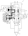
- FIGS. 1 to 5 a fluid pressure type striking device according to the embodiment and its operation will be described with reference to FIGS. 1 to 5.
- the upward direction and the downward direction in the state of actually being used for crushing concrete, rock, etc. (Figs. 1 to 5) will be referred to as "upward”.
- the fluid pressure type impact device 1 is a hydraulic type that uses oil as a fluid, for example.
- the hydraulic striking device 1 has a cylinder 2, a piston 3, and a chisel 4.
- the cylinder 2 is a tubular member having an inner peripheral surface 2a.
- a piston 3 is fitted inside the inner peripheral surface 2 a of the cylinder 2.
- the piston 3 has a cylindrical first small diameter portion 3a, a first large diameter portion 3b, an intermediate portion 3c, a second large diameter portion 3d, and a second small diameter portion in order from the upper side to the lower side. 3e.
- the upper ring-shaped surface of the first large diameter portion 3b is set as the piston upper pressure receiving surface 3u.
- the lower ring-shaped surface of the second large diameter portion is set as the piston lower pressure receiving surface 3v.
- the area of the piston upper pressure receiving surface 3u is set smaller than the area of the piston lower pressure receiving surface 3v.
- the first chamber 5 is provided from one end side in the axial direction of the cylinder 2 (lower side in the drawing) toward the other end side in the axial direction (upper side in the drawing).
- the second chamber 6, the pilot chamber 8 and the third chamber 7 are each formed as a ring-shaped groove. That is, the first chamber 5, the second chamber 6, the pilot chamber 8 and the third chamber 7 are defined by the inner peripheral surface 2 a of the cylinder 2 and the outer peripheral surface 3 s of the piston 3. Further, the arrangement of the first chamber 5, the second chamber 6, the pilot chamber 8, and the third chamber 7 depends on the position of the piston 3 to be described later during the reciprocating motion in the axial direction (the vertical direction in the drawing).
- the third chamber 7 and the pilot chamber 8 are connected or disconnected, and the second chamber 6 and the pilot chamber 8 are connected or disconnected.
- the chisel 4 is a pile-shaped member, and includes a tip portion 4a having a pierceable shape and a flat rear end surface (top surface in the drawing) 4c from the lower side to the upper side. It has a rear end portion 4b.
- the chisel 4 is inserted from an opening at one end (lower end in the drawing) of the cylinder 2 in the axial direction, and the tip portion 4a which is a part of the chisel 4 is installed so as to project from one end of the cylinder 2 in the axial direction.
- the rear end surface 4 c of the chisel 4 is further hit from the one end of the cylinder 2 by being hit by the piston 3.
- first chamber 5 and the second chamber 6 are connected by a first flow path (flow path) 11.
- a check valve 13 is provided in the middle of the first flow path. The check valve 13 allows the oil to flow from the second chamber 6 into the first chamber 5, but prevents the oil from flowing from the first chamber 5 into the second chamber 6.
- the first chamber 5 and the third chamber 7 are communicated with each other by a second flow passage 12.
- a part of the second flow passage 12 or the entire second flow passage 12 has a throttle portion 14.
- the throttle portion 14 is a portion where the passage of oil is set to be narrow, and does not allow the oil to flow more than necessary.
- the fluid pressure impact device 1 further includes a hydraulic pump 10, a switching valve 30, an oil tank 50, and an accumulator 60.
- the hydraulic pump 10 is in constant communication with the third chamber 7 in the cylinder 2 via a passage 24 branched from the passage 21.
- the hydraulic pump 10 continues to supply the fluid to the third chamber 7 through the passage 24 during the operation of the fluid pressure striking device 1. Therefore, the third chamber 7 is always in a high fluid pressure state.
- the switching valve 30 has a role of switching the stroke direction of the piston 3.
- the switching valve 30 includes a switching valve cylinder 31 and a valve 32.
- the switching valve cylinder 31 has a tubular shape, and an opening at the upper end and an opening at the lower end are connected by a communication passage 37.
- the valve 32 is fitted in the switching valve cylinder 31 so as to be slidable in the axial direction (vertical direction in the drawing).
- the valve 32 has a columnar valve first small diameter portion 32a, a valve first large diameter portion 32b, a connecting portion 32c, a valve second large diameter portion 32d, and a valve second small diameter portion 32e, which are arranged in this order from the bottom to the top. ..
- the ring-shaped surface on the lower side of the valve first large diameter portion 32b is set as a valve lower pressure receiving surface 32v.
- the ring-shaped surface on the upper side of the valve second large diameter portion 32d is set as the valve upper pressure receiving surface 32u.
- the area of the valve lower pressure receiving surface 32v is set smaller than the area of the valve upper pressure receiving surface 32u.
- a valve high pressure chamber 33, a valve reversal chamber 34, a valve low pressure chamber 35, and a valve pilot chamber 36 are formed as ring-shaped grooves on the inner wall of the switching valve cylinder 31 from the bottom to the top.
- the valve high-pressure chamber 33, the valve reversal chamber 34, the valve low-pressure chamber 35, and the valve pilot chamber 36 are arranged according to the valve high-pressure chamber 33 depending on the position of the valve 32, which will be described later, during the reciprocating movement in the vertical direction.
- the valve reversal chamber 34 is connected or disconnected, and the valve low pressure chamber 35 and the valve reversal chamber 34 are connected or disconnected.
- valve high pressure chamber 33 is always in communication with the hydraulic pump 10 via the passage 21.
- the hydraulic pump 10 continues to supply oil to the valve high pressure chamber 33 via the passage 21. Therefore, the valve high pressure chamber 33 is always in a high fluid pressure state.
- the valve reversal chamber 34 communicates with the first chamber 5 via the passage 22.
- the valve low pressure chamber 35 communicates with the second chamber 6 via the passage 25.
- the valve pilot chamber 36 communicates with the pilot chamber 8 via the passage 26.
- the oil tank 50 communicates with the second chamber 6 via a passage 27 communicating with the oil tank 50, which is a receiving place for the discharged oil.
- the accumulator 60 is internally provided with a chamber 60a having a contracting force, and communicates with the passages 21, 23 and 24, the third chamber 7 and the valve that communicate with the passages 21, 23 and 24. It serves to keep the fluid pressure in the high-pressure chamber 33 from decreasing. For example, when the fluid pressure drops, the accumulator 60 discharges the oil previously taken into the chamber 60a by the chamber 60a due to the contracting force. With such a function, the accumulator 60 can suppress the fluid pressures of the passages 21, 23, 24 communicating with each other, the third chamber 7 communicating with the passages 21, 23, 24 and the valve high pressure chamber 33 from decreasing.
- FIG. 2 shows a state immediately after the piston 3 hits the rear end surface 4c of the chisel 4. That is, the tip end 4a of the chisel 4 is in a state of being pressed against a crushed portion such as concrete or bedrock.
- the hydraulic pump 10 continues to supply oil to the third chamber 7 via the passage 21 and the passage 24 branched from the passage 21. Further, the hydraulic pump 10 continues to supply oil to the valve high pressure chamber 33 via the passage 21. Therefore, the third chamber 7 and the valve high pressure chamber 33 are in a high fluid pressure state.
- the pilot chamber 8 communicates with the third chamber 7 depending on the position of the piston 3 as shown in FIG.
- the valve reversal chamber 34 and the valve high pressure chamber 33 communicate with each other. Therefore, the pilot chamber 8 and the valve reversal chamber 34 are in a high fluid pressure state.
- the pilot chamber 8 communicates with the valve pilot chamber 36 via the passage 26.
- the valve reversal chamber 34 communicates with the first chamber 5 via the passage 22. Therefore, the valve pilot chamber 36 and the first chamber 5 are also in a high fluid pressure state.
- the first chamber 5 and the third chamber 7 shown in FIG. 2 are both in a high fluid pressure state, and the same fluid pressure is applied to the piston upper pressure receiving surface 3u and the piston lower pressure receiving surface 3v per unit area. ..
- the piston lower pressure receiving surface 3v is set to be wider than the piston upper pressure receiving surface 3u. Therefore, in the state where the fluid pressure applied per unit area is the same, the piston 3 moves toward the other end side (upper side in the drawing) of the cylinder 2 in the axial direction as shown by the arrow A in FIG.
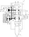
- FIG. 3 shows a state in which the piston 3 moves toward the other end of the cylinder 2 in the axial direction and reaches the top dead center.
- the first large-diameter portion 3b closes the gap between the third chamber 7 and the pilot chamber 8, so that the third chamber 7 and the pilot chamber 8 are cut off from each other.
- the second chamber 6 and the pilot chamber 8 communicate with each other.
- oil does not flow into the pilot chamber 8.
- the second chamber 6 communicates with the oil tank 50 via the passage 27. Therefore, the pilot chamber 8 communicating with the second chamber 6 is in a low fluid pressure state.
- the pilot chamber 8 communicates with the valve pilot chamber 36 via the passage 26. Therefore, the valve pilot chamber 36 is also in a low fluid pressure state.
- valve pilot chamber 36 shown in FIG. 3 is in a low fluid pressure state.
- the valve high pressure chamber 33 communicates with the hydraulic pump 10 via the passage 21. Therefore, the valve high pressure chamber 33 is kept in a high fluid pressure state. Therefore, the valve high pressure chamber 33 is in a high fluid pressure state, and the high fluid pressure presses the valve lower pressure receiving surface 32v, so that the valve 32 moves in the direction of the arrow B, that is, toward the upper side in the drawing.
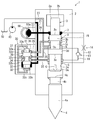
- FIG. 4 shows a state in which the valve 32 has moved upward and has reached the top dead center.
- the valve first large diameter portion 32 b closes the space between the valve high pressure chamber 33 and the valve reversal chamber 34.
- the valve high-pressure chamber 33 and the valve reversal chamber 34 are cut off from each other.
- the valve second large diameter portion 32d does not exist between the valve reversal chamber 34 and the valve low pressure chamber 35.
- the valve reversal chamber 34 communicates with the valve low pressure chamber 35.
- the valve low-pressure chamber 35 communicates with the second chamber 6 via the passage 25, and the second chamber 6 communicates with the oil tank 50 via the passage 27.
- the valve reversal chamber 34 communicating with the valve low pressure chamber 35 is in a low fluid pressure state.
- the first chamber 5 communicates with the valve reversing chamber 34 via the passage 22. Therefore, the first chamber 5 is also in a low fluid pressure state.
- the third chamber 7 communicates with the hydraulic pump 10 via the passage 21 and the passage 24. Therefore, the third chamber 7 is kept in a high fluid pressure state. Therefore, the inside of the third chamber 7 is in a high fluid pressure state, and the high fluid pressure presses the upper pressure receiving surface 3u, so that the high fluid pressure of the piston 3 is in the direction of arrow C, that is, one end side in the axial direction (lower side in the drawing). Move towards.
- FIG. 5 shows a state at the moment when the piston 3 moves toward one end side in the axial direction and the piston 3 hits the rear end surface 4c of the chisel 4.
- the first large-diameter portion 3b closes the space between the second chamber 6 and the pilot chamber 8 so that the second chamber 6 and the pilot chamber 8 are in communication with each other.
- the first large-diameter portion 3b of the piston 3 does not exist between the third chamber 7 and the pilot chamber 8, so that the third chamber 7 and the pilot chamber 8 communicate with each other.
- the third chamber 7 communicates with the hydraulic pump 10 via the passages 21 and 24. Therefore, both the third chamber 7 and the pilot chamber 8 are in a high fluid pressure state.
- the pilot chamber 8 communicates with the valve pilot chamber 36 via the passage 26. Therefore, the valve pilot chamber 36 is also in a high fluid pressure state. Further, the valve high pressure chamber 33 communicates with the hydraulic pump 10 via the passage 21. Therefore, the valve high pressure chamber 33 is also in a high fluid pressure state.
- the movement of the piston 3 expands the area of the third chamber 7, and the oil flows into the expanded area, so that the fluid pressure of the passages 21, 23, 24 and the third chamber 7 temporarily decreases.
- the oil previously stored in the one chamber 60a of the accumulator 60 at the stage of FIG. 3 is discharged by the contracting force of the one chamber 60a.
- both the valve high pressure chamber 33 and the valve pilot chamber 36 shown in FIG. 5 are in a high fluid pressure state.
- the area of the valve lower pressure receiving surface 32v is set smaller than the area of the valve upper pressure receiving surface 32u. Therefore, when the fluid pressure applied per unit area is the same, the valve 32 moves in the direction of arrow D, that is, in the downward direction in the drawing.
- the valve second large diameter portion 32d closes the gap between the valve low pressure chamber 35 and the valve reversal chamber 34 as shown in FIG. As a result, the valve low pressure chamber 35 and the valve reversal chamber 34 are cut off from each other.
- valve large diameter portion 32b does not exist between the valve high pressure chamber 33 and the valve reversing chamber 34.
- the valve high pressure chamber 33 and the valve reversal chamber 34 communicate with each other.
- the valve high pressure chamber 33 communicates with the hydraulic pump 10 via the passage 21. Therefore, the valve reversal chamber 34 communicating with the valve high pressure chamber 33 is also in a high fluid pressure state.
- the first chamber 5, which communicates with the valve reversing chamber 34 via the passage 22, also becomes in a high fluid pressure state.
- the fluid pressure type striking device 1 repeats the operation of FIGS. 2 to 5 while the oil is continuously supplied from the hydraulic pump 10.
- the piston 3 reciprocates in the axial direction of the cylinder 2 and repeatedly strikes the chisel 4.
- the tip portion 4a of the chisel 4 is repeatedly pressed against the crushing portion, and the crushing portion is crushed.
- the oil in the first chamber 5 is normally lowered.
- the oil in the first chamber 5 is rapidly boiled and vaporized, or the gas dissolved in the liquid is released from the liquid to generate bubbles inside the oil. , There is concern about cavitation and erosion.
- the fluid pressure striking device 1 has a first flow path 11 that connects the first chamber 5 and the second chamber 6.
- first chamber 5 becomes lower in pressure than the second chamber 6 when the piston 3 hits the chisel 4
- oil flows from the second chamber 6 into the first chamber 5 via the first flow path 11.
- the low pressure state in the first chamber 5 can be relieved.
- the second chamber 6 is near the first chamber 5, oil can be supplied to the first chamber 5 more quickly. Therefore, the low pressure state in the first chamber 5 when the chisel 4 is struck by the piston 3 is easily alleviated, and the occurrence of cavitation can be further suppressed.
- a check valve 13 is provided in the middle of the first flow path 11.
- the check valve 13 allows the oil to flow from the second chamber 6 into the first chamber 5, but prevents the oil from flowing from the first chamber 5 into the second chamber 6. Thereby, even when the first chamber 5 is switched from the low fluid pressure to the high fluid pressure, the fluid does not flow backward from the first chamber 5 to the second chamber 6. That is, since the high fluid pressure state of the first chamber 5 is maintained, the low pressure state of the first chamber 5 can be alleviated while operating the fluid pressure striking device 1 efficiently.
- the fluid pressure striking device 1 has a second flow path 12 that connects the first chamber 5 and the third chamber 7. Since the first chamber 5 has a lower pressure than the third chamber 7 when the piston 3 strikes the chisel, oil flows from the third chamber 7 into the first chamber 5 through the second flow path 12. Since the third chamber 7 has a high fluid pressure when the piston 3 strikes the chisel 4, a large amount of oil can be supplied to the first chamber 5. For this reason, the low pressure state in the first chamber 5 is more easily alleviated, and the occurrence of cavitation can be further suppressed.
- a part of the second flow passage 12 or the entire second flow passage 12 has a throttle portion 14.
- the throttle portion 14 is a portion where the passage of oil is set to be narrow, and does not allow the oil to flow more than necessary.
- an appropriate amount of oil flows from the third chamber 7 into the first chamber 5 via the flow path provided with the throttle portion 14. Therefore, the low pressure state of the first chamber 5 can be relaxed within an appropriate range without reducing the fluid pressure of the third chamber 7 to an extremely low level.
- the third chamber 7 is always in communication with the hydraulic pump 10. Therefore, the third chamber 7 is always in a high fluid pressure state. Since the third chamber 7 is constantly in the high fluid pressure state, the impact force with which the piston 3 is impacted by the chisel 4 becomes large. Therefore, the piston 3 receives a stronger repulsive force from the chisel 4 and slides to the other end side in the axial direction of the cylinder 2, so that the first chamber 5 is likely to be in a lower pressure state. Therefore, when the third chamber 7 is constantly in the high fluid pressure state, the frequency of cavitation originally increases.
- the low pressure of the first chamber 5 is reduced.
- the state can be relaxed, and the high occurrence frequency of cavitation peculiar to the case where the third chamber 7 is constantly in the high fluid pressure state can be suppressed.
- a fourth chamber 9 can be provided between the second chamber 6 and the third chamber 7.
- the fourth chamber 9 is formed by a ring-shaped groove provided on the inner peripheral surface 2 a of the cylinder 2. That is, the fourth chamber 9 is defined by the inner peripheral surface 2 a of the cylinder 2 and the outer peripheral surface 3 s of the piston 3.
- the fourth chamber 9 communicates with the first chamber 5 at the same time as the second channel 12 communicating with the third chamber 7 from the first chamber 5 or in place of the second channel 12.
- a third flow path (flow path) 15 can be provided. That is, the fluid supply unit may include the fourth chamber 9 in addition to the third chamber 7, or the fourth chamber 9 may be included in place of the third chamber 7.
- the first large diameter portion 3b of the piston 3 blocks between the third chamber 7 and the fourth chamber 9. Therefore, the third chamber 7 and the fourth chamber 9 are in communication with each other.
- the first large diameter portion 3b of the piston 3 also ends in one end side of the cylinder 2 in the axial direction. Move to.
- the first large diameter portion 3b of the piston 3 does not block the third chamber 7 and the fourth chamber 9, and the third chamber 7 and the fourth chamber 9 communicate with each other.
- the third chamber 7 communicates with the hydraulic pump 10 via the passage 21 and the passage 24. Therefore, the third chamber 7 is in a high fluid pressure state. Therefore, the fourth chamber 9 communicating with the third chamber 7 is also in a high fluid pressure state.
- the fluid supply unit is the third chamber 7 and the second flow path 12 is provided, oil is continuously supplied from the third chamber 7 to the first chamber 5 while the piston 3 is descending.
- the fluid supply unit includes the fourth chamber 9 instead of the third chamber 7, as shown in FIGS.
- the inflow of oil from 9 to the first chamber 5 through the third flow path 15 is limited only when the piston 3 strikes the chisel 4. Therefore, it is possible to avoid wasteful oil outflow from the third chamber 7. That is, it is possible to more reliably suppress the occurrence of cavitation in the first chamber 5 while efficiently moving the fluid pressure impact device.
- the fluid pressure type impact device 1 is a hydraulic type that employs oil as a fluid, but the fluid is not particularly limited as long as it is a liquid fluid in which cavitation can occur, and may be water or the like.
- the third chamber 7 is always in a high fluid pressure state, but when the first chamber 5 is in a high fluid pressure state, the third chamber 7 is in a low fluid pressure state, and vice versa. When the first chamber 5 is in a low fluid pressure state, the third chamber 7 is in a high fluid pressure state, so that the piston 3 may reciprocate in the axial direction of the cylinder 2.
- the first chamber 5 and the second chamber 6 are provided between the inner peripheral surface 2a of the cylinder 2 and the outer peripheral surface 3s of the piston 3.
- the third chamber 7, the pilot chamber 8 or the fourth chamber 9 are formed.
- the first chamber 5, the second chamber 6, the third chamber 7, the pilot chamber 8, or the fourth chamber 9 is formed. It may be formed.
- the fluid pressure type striking device 1 has both the first flow passage 11 and the second flow passage 12, but has only the first flow passage 11, the second flow passage 12, or the third flow passage 15. May be
- the check valve 13 is provided in the first flow passage 11, but may be provided in the second flow passage 12 or the third flow passage 15. Although the narrowed portion 14 is included in the second flow passage 12, it may be provided in the first flow passage 11 or the third flow passage 15.
- the fluid supply unit capable of supplying the fluid to the first chamber is the second chamber, the third chamber, or the fourth chamber in the above-described embodiment, but the fluid supply unit is used when the piston strikes the chisel. It is sufficient that the fluid can be supplied to the extent that the low pressure state of the first chamber can be relaxed.
- a separate hydraulic tank may be provided to supply fluid to the first chamber as needed.
- Example 1 In the first embodiment, only the first flow passage 11 (and the check valve 13) in the fluid pressure striking device 1 shown in FIG. 1 described above is provided, and the second flow passage 12 (and the throttle portion 14) is provided.
- the fluid pressure in the first chamber 5 and the gas pressure in the gas chamber 2b were measured when there was no gas.
- the results of Example 1 are shown in FIG.
- X represents the gas pressure in the gas chamber 2b.
- Y represents the fluid pressure in the first chamber 5.
- H indicates the time when the piston 3 hits the chisel 4.
- V shifts from FIG. 5 to FIG.
- the chamber 5 also shows the time when it is in a high fluid pressure state.
- the comparative example is a case in which both the first flow passage 11 (and the check valve 13) and the second flow passage 12 (and the throttle portion 14) in the fluid pressure type striking device 1 shown in FIG.
- the fluid pressure in the first chamber 5 and the gas pressure in the gas chamber 2b were measured.
- the results of the comparative example are shown in FIG. FIG. 9 is represented by the same method as FIG.
- Example 1 As shown in FIG. 5, when the piston 3 hits the chisel 4 (at the time point H in FIG. 6), the fluid pressure in the first chamber 5 decreases, but When the first chamber 5 reaches the high pressure state (time V in FIG. 6), the fluid pressure in the first chamber 5 becomes smaller than that in the comparative example (see FIG. 9). There is. It is considered that this is because even if bubbles are generated, the rapid collapse of the bubbles is suppressed, so that the high pressure state is also suppressed. That is, it is considered that Example 1 can suppress the rapid collapse of bubbles as compared with the comparative example, and suppresses the occurrence of cavitation and erosion accompanying it. It is considered that this is because the first flow path 11 (and the check valve 13) is provided to alleviate the low pressure state of the first chamber 5 when the piston 3 strikes the chisel 4.
- Example 2 when the piston 3 hits the chisel 4 as shown in FIG. 5 (time H in FIG. 7), the fluid pressure in the first chamber 5 decreases, but When the first chamber 5 reaches the high pressure state (time V in FIG. 7), the fluid pressure in the first chamber 5 becomes smaller than that in the comparative example (see FIG. 9). There is. It is considered that this is because even if bubbles are generated, the rapid collapse of the bubbles is suppressed, so that the high pressure state is also suppressed. That is, it is considered that Example 2 can suppress the rapid collapse of bubbles as compared with the Comparative Example, and suppresses the occurrence of cavitation and erosion accompanying it.
- the second flow path 12 (and the throttle portion 14) is provided, and the low pressure state of the first chamber 5 when the piston 3 strikes the chisel 4 is relaxed. Moreover, the degree of the high pressure state of the second embodiment is smaller than that of the first embodiment. It is considered that this is because the fluid pressure in the third chamber 7 is higher than the fluid pressure in the second chamber 6 and sufficient oil is supplied to the first chamber 5.
- Example 3 when the piston 3 hits the chisel 4 as shown in FIG. 5 (at the point H in FIG. 8), the fluid pressure in the first chamber 5 decreases, but When the first chamber 5 reaches the high pressure state (time V in FIG. 8), the fluid pressure in the first chamber 5 becomes smaller than that in the comparative example (see FIG. 9). There is. It is considered that this is because even if bubbles are generated, the rapid collapse of the bubbles is suppressed, so that the high pressure state is also suppressed. That is, it is considered that Example 3 can suppress the rapid collapse of bubbles as compared with the comparative example, and suppresses the occurrence of cavitation and erosion accompanying it.
- the first flow passage 11 and the check valve 13
- the second flow passage 12 and the throttle portion 14
- the third embodiment is smaller in the high pressure state than the first and second embodiments. It is considered that this is because the oil was properly supplied from both the second chamber 6 and the third chamber 7.
Landscapes
- Engineering & Computer Science (AREA)
- Mechanical Engineering (AREA)
- Physics & Mathematics (AREA)
- Fluid Mechanics (AREA)
- Percussive Tools And Related Accessories (AREA)
Priority Applications (2)
| Application Number | Priority Date | Filing Date | Title |
|---|---|---|---|
| US17/296,538 US11850717B2 (en) | 2018-11-22 | 2019-11-07 | Fluid pressure striking device |
| EP19886108.0A EP3885076A4 (en) | 2018-11-22 | 2019-11-07 | Fluid pressure striking device |
Applications Claiming Priority (2)
| Application Number | Priority Date | Filing Date | Title |
|---|---|---|---|
| JP2018219081A JP7171035B2 (ja) | 2018-11-22 | 2018-11-22 | 流体圧式打撃装置 |
| JP2018-219081 | 2018-11-22 |
Publications (1)
| Publication Number | Publication Date |
|---|---|
| WO2020105447A1 true WO2020105447A1 (ja) | 2020-05-28 |
Family
ID=70773416
Family Applications (1)
| Application Number | Title | Priority Date | Filing Date |
|---|---|---|---|
| PCT/JP2019/043632 Ceased WO2020105447A1 (ja) | 2018-11-22 | 2019-11-07 | 流体圧式打撃装置 |
Country Status (4)
| Country | Link |
|---|---|
| US (1) | US11850717B2 (https=) |
| EP (1) | EP3885076A4 (https=) |
| JP (1) | JP7171035B2 (https=) |
| WO (1) | WO2020105447A1 (https=) |
Families Citing this family (1)
| Publication number | Priority date | Publication date | Assignee | Title |
|---|---|---|---|---|
| KR102317232B1 (ko) * | 2020-01-08 | 2021-10-22 | 주식회사 현대에버다임 | 유압 브레이커 |
Citations (6)
| Publication number | Priority date | Publication date | Assignee | Title |
|---|---|---|---|---|
| JPS6393577A (ja) * | 1986-10-08 | 1988-04-23 | 日本ニユ−マチツク工業株式会社 | 衝撃動工具 |
| JPH07214479A (ja) * | 1994-02-02 | 1995-08-15 | Matsuda Astec Kk | 油圧衝撃工具 |
| JP2015163425A (ja) * | 2014-01-30 | 2015-09-10 | 古河ロックドリル株式会社 | 液圧式打撃装置 |
| JP2015163426A (ja) | 2014-01-30 | 2015-09-10 | 古河ロックドリル株式会社 | 液圧式打撃装置 |
| JP2016140929A (ja) * | 2015-01-30 | 2016-08-08 | 古河ロックドリル株式会社 | 液圧式打撃装置、並びにバルブタイミングの切換方法およびバルブポートの設定方法 |
| JP2018138321A (ja) * | 2017-02-24 | 2018-09-06 | 古河ロックドリル株式会社 | 液圧式打撃装置 |
Family Cites Families (11)
| Publication number | Priority date | Publication date | Assignee | Title |
|---|---|---|---|---|
| US3780621A (en) | 1971-06-07 | 1973-12-25 | Atlas Copco Ab | Hydraulic fluid actuated percussion tool |
| JPS5837569Y2 (ja) | 1980-05-19 | 1983-08-24 | 株式会社 帝国鑿岩機製作所 | 打撃装置 |
| US4401030A (en) * | 1981-06-15 | 1983-08-30 | Gator Manufacturing, Inc. | Portable marking tool |
| DE3221758A1 (de) * | 1982-06-09 | 1983-12-15 | Hartmann & Lämmle GmbH & Co KG, 7255 Rutesheim | Hydraulische antriebsvorrichtung |
| GB9314145D0 (en) * | 1993-07-08 | 1993-08-18 | Savair Ltd | Pneumatic cylinder and control valve therefor |
| DE4404009C1 (de) | 1994-02-09 | 1995-04-27 | Klemm Guenter | Fluidbetätigter Schlaghammer |
| EP1731271A1 (de) * | 2005-06-09 | 2006-12-13 | Netter Gmbh | Pneumatisch arbeitender Klopfer sowie Verfahren zum Betreiben eines pneumatisch arbeitenden Klopfers |
| US8968204B2 (en) * | 2006-06-12 | 2015-03-03 | Transonic Systems, Inc. | System and method of perivascular pressure and flow measurement |
| US20080236297A1 (en) | 2007-01-23 | 2008-10-02 | Geoff Van Fleet | Acoustically compatible insert for an ultrasonic probe |
| JP2013233595A (ja) * | 2010-08-27 | 2013-11-21 | Teisaku:Kk | 流体圧式打撃装置 |
| US10335043B2 (en) | 2015-04-06 | 2019-07-02 | Thomas Jefferson University | Implantable vital sign sensor |
-
2018
- 2018-11-22 JP JP2018219081A patent/JP7171035B2/ja active Active
-
2019
- 2019-11-07 WO PCT/JP2019/043632 patent/WO2020105447A1/ja not_active Ceased
- 2019-11-07 US US17/296,538 patent/US11850717B2/en active Active
- 2019-11-07 EP EP19886108.0A patent/EP3885076A4/en active Pending
Patent Citations (6)
| Publication number | Priority date | Publication date | Assignee | Title |
|---|---|---|---|---|
| JPS6393577A (ja) * | 1986-10-08 | 1988-04-23 | 日本ニユ−マチツク工業株式会社 | 衝撃動工具 |
| JPH07214479A (ja) * | 1994-02-02 | 1995-08-15 | Matsuda Astec Kk | 油圧衝撃工具 |
| JP2015163425A (ja) * | 2014-01-30 | 2015-09-10 | 古河ロックドリル株式会社 | 液圧式打撃装置 |
| JP2015163426A (ja) | 2014-01-30 | 2015-09-10 | 古河ロックドリル株式会社 | 液圧式打撃装置 |
| JP2016140929A (ja) * | 2015-01-30 | 2016-08-08 | 古河ロックドリル株式会社 | 液圧式打撃装置、並びにバルブタイミングの切換方法およびバルブポートの設定方法 |
| JP2018138321A (ja) * | 2017-02-24 | 2018-09-06 | 古河ロックドリル株式会社 | 液圧式打撃装置 |
Non-Patent Citations (1)
| Title |
|---|
| See also references of EP3885076A4 |
Also Published As
| Publication number | Publication date |
|---|---|
| US11850717B2 (en) | 2023-12-26 |
| EP3885076A4 (en) | 2022-08-10 |
| US20220024012A1 (en) | 2022-01-27 |
| EP3885076A1 (en) | 2021-09-29 |
| JP2020082256A (ja) | 2020-06-04 |
| JP7171035B2 (ja) | 2022-11-15 |
Similar Documents
| Publication | Publication Date | Title |
|---|---|---|
| CN105916634B (zh) | 液压式冲击装置 | |
| WO2012026571A1 (ja) | 流体圧式打撃装置 | |
| JP6228234B2 (ja) | 可変容積蓄圧器 | |
| US10472797B2 (en) | Two step hydraulic breaker with automatic stroke adjustment | |
| KR20160118210A (ko) | 액압식 타격 장치 | |
| KR101751409B1 (ko) | 유압타격장치용 타격몸체 | |
| KR102593990B1 (ko) | 액압식 타격장치 | |
| CN102410275A (zh) | 无阀控自配流气液联合做功式冲击器 | |
| CN105710845B (zh) | 具有可变冲程控制的液压锤 | |
| WO2020105447A1 (ja) | 流体圧式打撃装置 | |
| KR101797659B1 (ko) | 자동 윤활유 공급장치, 그 제어방법 및 자동 윤활유 공급장치를 구비하는 유압 브레이커 | |
| CA2808373C (en) | Membrane pump and method for adjusting same | |
| JP6480201B2 (ja) | 液圧式打撃装置 | |
| JP2015532370A (ja) | 掘削機用の流体ハンマー装置 | |
| KR101490597B1 (ko) | 유압브레이커 | |
| JP6757682B2 (ja) | 液圧式打撃装置 | |
| JP2017078507A (ja) | 片ロッド形複動油圧シリンダ | |
| KR101384752B1 (ko) | 유압 해머 장치 | |
| JP2759497B2 (ja) | 打撃工具 | |
| KR101644473B1 (ko) | 타격 효율을 향상시키는 부스팅 장치를 갖는 타격장치 | |
| RU2443863C2 (ru) | Устройство ударного действия | |
| KR101626519B1 (ko) | 유압 브레이커 | |
| JP2020082256A5 (https=) | ||
| RU2291299C1 (ru) | Устройство ударного действия | |
| JPH0763940B2 (ja) | 衝撃動工具 |
Legal Events
| Date | Code | Title | Description |
|---|---|---|---|
| 121 | Ep: the epo has been informed by wipo that ep was designated in this application |
Ref document number: 19886108 Country of ref document: EP Kind code of ref document: A1 |
|
| NENP | Non-entry into the national phase |
Ref country code: DE |
|
| ENP | Entry into the national phase |
Ref document number: 2019886108 Country of ref document: EP Effective date: 20210622 |