WO2020105327A1 - 偏光板積層体 - Google Patents
偏光板積層体Info
- Publication number
- WO2020105327A1 WO2020105327A1 PCT/JP2019/040857 JP2019040857W WO2020105327A1 WO 2020105327 A1 WO2020105327 A1 WO 2020105327A1 JP 2019040857 W JP2019040857 W JP 2019040857W WO 2020105327 A1 WO2020105327 A1 WO 2020105327A1
- Authority
- WO
- WIPO (PCT)
- Prior art keywords
- polarizing plate
- layer
- resin
- retardation
- plate
- Prior art date
- Legal status (The legal status is an assumption and is not a legal conclusion. Google has not performed a legal analysis and makes no representation as to the accuracy of the status listed.)
- Ceased
Links
Images


Classifications
-
- B—PERFORMING OPERATIONS; TRANSPORTING
- B32—LAYERED PRODUCTS
- B32B—LAYERED PRODUCTS, i.e. PRODUCTS BUILT-UP OF STRATA OF FLAT OR NON-FLAT, e.g. CELLULAR OR HONEYCOMB, FORM
- B32B7/00—Layered products characterised by the relation between layers; Layered products characterised by the relative orientation of features between layers, or by the relative values of a measurable parameter between layers, i.e. products comprising layers having different physical, chemical or physicochemical properties; Layered products characterised by the interconnection of layers
- B32B7/02—Physical, chemical or physicochemical properties
- B32B7/023—Optical properties
-
- G—PHYSICS
- G02—OPTICS
- G02B—OPTICAL ELEMENTS, SYSTEMS OR APPARATUS
- G02B5/00—Optical elements other than lenses
- G02B5/30—Polarising elements
-
- G—PHYSICS
- G02—OPTICS
- G02F—OPTICAL DEVICES OR ARRANGEMENTS FOR THE CONTROL OF LIGHT BY MODIFICATION OF THE OPTICAL PROPERTIES OF THE MEDIA OF THE ELEMENTS INVOLVED THEREIN; NON-LINEAR OPTICS; FREQUENCY-CHANGING OF LIGHT; OPTICAL LOGIC ELEMENTS; OPTICAL ANALOGUE/DIGITAL CONVERTERS
- G02F1/00—Devices or arrangements for the control of the intensity, colour, phase, polarisation or direction of light arriving from an independent light source, e.g. switching, gating or modulating; Non-linear optics
- G02F1/01—Devices or arrangements for the control of the intensity, colour, phase, polarisation or direction of light arriving from an independent light source, e.g. switching, gating or modulating; Non-linear optics for the control of the intensity, phase, polarisation or colour
- G02F1/13—Devices or arrangements for the control of the intensity, colour, phase, polarisation or direction of light arriving from an independent light source, e.g. switching, gating or modulating; Non-linear optics for the control of the intensity, phase, polarisation or colour based on liquid crystals, e.g. single liquid crystal display cells
-
- G—PHYSICS
- G02—OPTICS
- G02F—OPTICAL DEVICES OR ARRANGEMENTS FOR THE CONTROL OF LIGHT BY MODIFICATION OF THE OPTICAL PROPERTIES OF THE MEDIA OF THE ELEMENTS INVOLVED THEREIN; NON-LINEAR OPTICS; FREQUENCY-CHANGING OF LIGHT; OPTICAL LOGIC ELEMENTS; OPTICAL ANALOGUE/DIGITAL CONVERTERS
- G02F1/00—Devices or arrangements for the control of the intensity, colour, phase, polarisation or direction of light arriving from an independent light source, e.g. switching, gating or modulating; Non-linear optics
- G02F1/01—Devices or arrangements for the control of the intensity, colour, phase, polarisation or direction of light arriving from an independent light source, e.g. switching, gating or modulating; Non-linear optics for the control of the intensity, phase, polarisation or colour
- G02F1/13—Devices or arrangements for the control of the intensity, colour, phase, polarisation or direction of light arriving from an independent light source, e.g. switching, gating or modulating; Non-linear optics for the control of the intensity, phase, polarisation or colour based on liquid crystals, e.g. single liquid crystal display cells
- G02F1/133—Constructional arrangements; Operation of liquid crystal cells; Circuit arrangements
- G02F1/1333—Constructional arrangements; Manufacturing methods
- G02F1/1335—Structural association of cells with optical devices, e.g. polarisers or reflectors
-
- G—PHYSICS
- G02—OPTICS
- G02F—OPTICAL DEVICES OR ARRANGEMENTS FOR THE CONTROL OF LIGHT BY MODIFICATION OF THE OPTICAL PROPERTIES OF THE MEDIA OF THE ELEMENTS INVOLVED THEREIN; NON-LINEAR OPTICS; FREQUENCY-CHANGING OF LIGHT; OPTICAL LOGIC ELEMENTS; OPTICAL ANALOGUE/DIGITAL CONVERTERS
- G02F1/00—Devices or arrangements for the control of the intensity, colour, phase, polarisation or direction of light arriving from an independent light source, e.g. switching, gating or modulating; Non-linear optics
- G02F1/01—Devices or arrangements for the control of the intensity, colour, phase, polarisation or direction of light arriving from an independent light source, e.g. switching, gating or modulating; Non-linear optics for the control of the intensity, phase, polarisation or colour
- G02F1/13—Devices or arrangements for the control of the intensity, colour, phase, polarisation or direction of light arriving from an independent light source, e.g. switching, gating or modulating; Non-linear optics for the control of the intensity, phase, polarisation or colour based on liquid crystals, e.g. single liquid crystal display cells
- G02F1/133—Constructional arrangements; Operation of liquid crystal cells; Circuit arrangements
- G02F1/1333—Constructional arrangements; Manufacturing methods
- G02F1/1335—Structural association of cells with optical devices, e.g. polarisers or reflectors
- G02F1/13363—Birefringent elements, e.g. for optical compensation
-
- G—PHYSICS
- G09—EDUCATION; CRYPTOGRAPHY; DISPLAY; ADVERTISING; SEALS
- G09F—DISPLAYING; ADVERTISING; SIGNS; LABELS OR NAME-PLATES; SEALS
- G09F9/00—Indicating arrangements for variable information in which the information is built-up on a support by selection or combination of individual elements
- G09F9/30—Indicating arrangements for variable information in which the information is built-up on a support by selection or combination of individual elements in which the desired character or characters are formed by combining individual elements
Definitions
- the present invention relates to a polarizing plate laminate, and also relates to a retardation plate laminate and an image display device.
- an image display device configured to emit linearly polarized light that has passed through a linearly polarizing plate after passing through a retardation film may have rainbow-colored spots when viewed with polarized sunglasses. Occurs.
- An object of the present invention is to provide an image display device in which a reduction in visibility and the occurrence of rainbow color spots are suppressed when the image display device is viewed with polarized sunglasses on. Moreover, it aims at providing the polarizing plate laminated body and retardation plate laminated body used for manufacture of such an image display apparatus.
- the present invention provides the following polarizing plate laminate, retardation plate laminate, and image display device.
- a linear polarizing plate, a retardation plate, and a light diffusion layer are provided in this order,
- the absorption axis of the linear polarizing plate and the slow axis of the retardation plate are non-parallel and non-orthogonal,
- the in-plane retardation value Re (550) at the measurement wavelength of 550 nm of the retardation plate is 3000 nm or more
- a polarizing plate laminate in which the internal haze of the light diffusion layer is 60% or more.
- a retardation plate and a light diffusion layer are provided in this order,
- the in-plane retardation value Re (550) at the measurement wavelength of 550 nm of the retardation plate is 3000 nm or more,
- a retardation plate laminate in which the internal haze value of the light diffusion layer is 60% or more.
- An image display panel that emits image light composed of linearly polarized light The retardation plate laminate according to [8] arranged on the viewing side of the image display panel, The image display device, wherein the retardation plate laminate is arranged such that the light diffusion layer is located on the viewing side of the retardation plate.
- the image display device according to [9] wherein the image display panel includes an image forming element.
- the polarizing plate laminate of the present invention has a constitution in which a linear polarizing plate is laminated on the retardation plate laminate of the present invention, and the linear polarizing plate is laminated on the retardation plate constituting the retardation plate laminate. ..
- FIG. 1 is a schematic sectional view schematically showing an example of a polarizing plate laminate of the present invention.
- the polarizing plate laminated body 10 includes a linear polarizing plate 11, a retardation plate 12, and a light diffusion layer 13 which are laminated in this order.
- the polarizing plate laminate 10 is arranged in the image display device, it is arranged so that the light diffusion layer 13 side is the viewing side on the front side of the image display device.
- the angle formed by the absorption axis of the linear polarizing plate 11 and the slow axis of the retardation plate 12 is non-parallel and non-orthogonal, for example, 1 ° to 89 °, and 30 °. It may be up to 60 °.
- FIG. 2 is a schematic sectional view schematically showing another example of the polarizing plate laminate of the present invention.
- the polarizing plate laminate 10 in addition to the layer structure shown in FIG. 1, the polarizing plate laminate 10 further includes an adhesive layer 14 laminated on the surface of the linear polarizing plate 11 opposite to the retardation plate 12. The configuration may be provided.
- the polarizing plate laminate 10 shown in FIGS. 1 and 2 may be configured to further include a front plate laminated on the surface of the light diffusion layer 13 opposite to the retardation plate 12.
- the polarizing plate laminate 10 satisfies the following condition i and condition ii. i)
- the in-plane retardation value Re (550) at the measurement wavelength of 550 nm of the retardation plate 12 is 3000 nm or more.
- the internal haze of the light diffusion layer 13 is 60% or more.
- the polarizing plate laminate 10 can suppress the reduction in visibility and the occurrence of iridescent color spots when the image display device is viewed with polarized sunglasses. ..
- the thickness of the polarizing plate laminate 10 is preferably 30 ⁇ m to 500 ⁇ m, more preferably 30 ⁇ m to 200 ⁇ m, and further preferably 30 ⁇ m to 150 ⁇ m from the viewpoint of thinning.
- the retardation plate 12 is an optical element having a function of providing a phase difference between an electric field vibration direction (polarization plane) of incident light and an electric field vibration direction orthogonal to the electric field vibration direction.
- the retardation plate 12 according to the present invention has an in-plane retardation value Re (550) of 3000 nm or more at a measurement wavelength of 550 nm.
- the in-plane retardation value Re of the retardation plate 12 is such that the refractive index in the in-plane slow axis direction is nx, the refractive index in the in-plane fast axis direction (direction orthogonal to the in-plane slow axis direction) is ny,
- the in-plane retardation value Re (550) of the retardation plate 12 makes it easy to configure the polarizing plate laminate 10 that suppresses the occurrence of iridescent color spots when the image display device is viewed with polarized sunglasses. From this viewpoint, it is preferably 3500 nm or more.
- the in-plane retardation value Re (550) of the retardation plate 12 is preferably 30,000 nm or less.
- the retardation plate 12 includes a stretched film and a layer formed by using a liquid crystal compound (hereinafter referred to as “liquid crystal layer”).
- liquid crystal layer a liquid crystal compound
- other layers used in the manufacturing process of the liquid crystal layer may be incorporated in the polarizing plate laminate 10 together with the liquid crystal layer.
- the retardation plate 12 that is a target for calculating the optical characteristics of the above formula (1) means only a layer that exhibits a retardation, that is, a stretched film or a liquid crystal layer.
- the retardation plate 12 may be a single layer or multiple layers.
- the in-plane retardation Re may be obtained by the above formula (1) to find the in-plane retardation of the single-layer retardation plate 12 itself.
- the in-plane retardation of the multi-layer retardation plate 12 may be obtained by the equation (1), or the in-plane retardation of each layer constituting the multi-layer retardation plate 12 may be calculated.
- the retardation value Re may be obtained, and the in-plane retardation value Re of the multi-layer retardation plate 12 may be combined and calculated from these by a known method.
- a stretched film is usually obtained by stretching a substrate.
- a roll in which the base material is wound around a roll is prepared, and the base material is continuously unwound from the winding body and unwound.
- the substrate is transferred to the heating furnace.
- the set temperature of the heating furnace is in the range of near the glass transition temperature (° C) of the substrate to [glass transition temperature +100] (° C), preferably near the glass transition temperature (° C) to [glass transition temperature +50] (° C) The range is.
- a uniaxial or biaxial thermal stretching treatment is performed by stretching the substrate in a traveling direction, or in a direction orthogonal to the traveling direction, adjusting the conveying direction and tension to incline at an arbitrary angle.
- the stretching ratio is usually 1.1 to 6 times, preferably 1.1 to 3.5 times.
- the method for stretching in the oblique direction is not particularly limited as long as the orientation axis can be continuously tilted at a desired angle, and a known stretching method can be adopted. Examples of such stretching methods include the methods described in JP-A-50-83482 and JP-A-2-113920.
- the thickness after stretching is determined by the thickness before stretching and the stretching ratio.
- the base material is usually a transparent base material.
- the transparent base material means a base material having a transparency capable of transmitting light, particularly visible light, and the transparency means a characteristic that a transmittance for a light ray having a wavelength of 380 to 780 nm is 80% or more.
- polyolefin resins such as polyethylene and polypropylene; cyclic polyolefin resins such as norbornene polymers; polyester resins such as polyethylene terephthalate and polyethylene naphthalate; (meth) acrylic acid, poly (meth) acrylic acid methyl ester, etc.
- (Meth) acrylic acid type resin cellulose ester type resin such as triacetyl cellulose, diacetyl cellulose and cellulose acetate propionate; vinyl alcohol type resin such as polyvinyl alcohol and polyvinyl acetate; polycarbonate type resin; polystyrene type resin; Arylate-based resin; polysulfone-based resin; polyether-sulfone-based resin; polyamide-based resin; polyimide-based resin; polyetherketone-based resin; polyphenylene sulfide-based resin; polyphenylene oxide-based resin, and mixtures and copolymers thereof.
- cellulose ester type resin such as triacetyl cellulose, diacetyl cellulose and cellulose acetate propionate
- vinyl alcohol type resin such as polyvinyl alcohol and polyvinyl acetate
- polycarbonate type resin polystyrene type resin
- Arylate-based resin polysulfone-based resin
- polyether-sulfone-based resin
- polyethylene terephthalate polymethacrylic acid ester, cellulose ester, cyclic olefin resin or polycarbonate is preferable.
- (meth) acrylic acid means “at least one of acrylic acid and methacrylic acid”.
- Cellulose ester is one in which some or all of the hydroxyl groups contained in cellulose have been esterified, and can be easily obtained from the market. Further, the cellulose ester base material can be easily obtained from the market. Examples of commercially available cellulose ester substrates include "Fujitac (registered trademark) film” (Fuji Film Co., Ltd.); “KC8UX2M”, “KC8UY” and “KC4UY” (Konica Minolta Opto Co., Ltd.) and the like. ..
- Examples of the (meth) acrylic resin include homopolymers of methacrylic acid alkyl ester or acrylic acid alkyl ester, and copolymers of methacrylic acid alkyl ester and acrylic acid alkyl ester.
- Specific examples of the methacrylic acid alkyl ester include methyl methacrylate, ethyl methacrylate and propyl methacrylate
- specific examples of the acrylic acid alkyl ester include methyl acrylate, ethyl acrylate and propyl acrylate.
- a (meth) acrylic resin a commercially available general-purpose (meth) acrylic resin can be used.
- As the (meth) acrylic resin a so-called impact resistant (meth) acrylic resin may be used.
- (meth) acrylic means at least one selected from acrylic and methacrylic.
- (meth) acryloyl means at least one selected from acrylic and methacrylic.
- (meth) acrylate means at least one selected from acrylic and methacrylic.
- the rubber particles are preferably acrylic particles.
- the acrylic rubber particles have rubber elasticity obtained by polymerizing an acrylic monomer such as butyl acrylate or 2-ethylhexyl acrylate, which has an acrylic acid alkyl ester as a main component, in the presence of a polyfunctional monomer. It is a particle.
- the acrylic rubber particles may be particles in which such particles having rubber elasticity are formed in a single layer, or may be a multilayer structure having at least one rubber elastic layer.
- acrylic rubber particles having a multi-layered structure those having a rubber elastic particle as described above as a core and surrounding the particles with a hard methacrylic acid alkyl ester-based polymer, a hard methacrylic acid alkyl ester-based polymer are used.
- the rubber particles formed of the elastic layer usually have an average diameter of about 50 to 400 nm.
- the content of rubber particles in the (meth) acrylic resin is usually about 5 to 50 parts by mass per 100 parts by mass of the (meth) acrylic resin. Since the (meth) acrylic resin and the acrylic rubber particles are commercially available in the state where they are mixed, the commercially available products can be used. Examples of commercially available (meth) acrylic resins containing acrylic rubber particles include “HT55X” and “Technoloy S001” sold by Sumitomo Chemical Co., Ltd. "Technoloy S001" is sold in film form.
- Cycloolefin resins are easily available from the market. Examples of commercially available cyclic olefin resins include "Topas” (registered trademark) [Ticona (Germany)], “Arton” (registered trademark) [JSR Corporation], “ZEONOR” (registered trademark) [Japan] Zeon Corporation], “ZEONEX” (registered trademark) [Japan Zeon Corporation] and “Apel” (registered trademark) [Mitsui Chemicals, Inc.]. Such a cyclic olefin resin can be used as a substrate by forming a film by a known means such as a solvent casting method or a melt extrusion method.
- cyclic olefin resin base material a commercially available cyclic olefin resin base material can also be used.
- Commercially available cyclic olefin resin base materials include "ESCINA” (registered trademark) [Sekisui Chemical Co., Ltd.], “SCA40” (registered trademark) [Sekisui Chemical Co., Ltd.], “Zeonoa Film” (registered trademark) ) [Optes Corporation] and "Arton Film” (registered trademark) [JSR Corporation].
- the cyclic olefin-based resin is a copolymer of a cyclic olefin and an aromatic compound having a chain olefin or a vinyl group
- the content ratio of the structural unit derived from the cyclic olefin is equal to all structural units of the copolymer. On the other hand, it is usually 50 mol% or less, preferably 15 to 50 mol%.
- the chain olefin include ethylene and propylene
- examples of the aromatic compound having a vinyl group include styrene, ⁇ -methylstyrene and alkyl-substituted styrene.
- the cyclic olefin resin is a ternary copolymer of a cyclic olefin, a chain olefin, and an aromatic compound having a vinyl group
- the content ratio of the structural unit derived from the chain olefin is usually 5 to 80 mol% based on the total structural units of the copolymer. Is.
- Such a terpolymer has the advantage that the amount of expensive cyclic olefin used can be relatively small in the production thereof.
- the thickness of the stretched film forming the retardation plate 12 is not particularly limited, but is preferably 1 to 50 ⁇ m, more preferably 1 to 30 ⁇ m from the viewpoint of thinning.
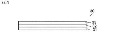
- FIG. 3 is a schematic cross-sectional view schematically showing an example of the liquid crystal laminate 30 obtained in the manufacturing process of the liquid crystal layer 33 which is the retardation plate 12.
- the liquid crystal laminate 30 is formed by laminating a base material layer 31, an alignment layer 32, and a liquid crystal layer 33 in this order.
- the base material layer 31 has a function as a support layer that supports the alignment layer 32 and the liquid crystal layer 33 formed on the base material layer 31.
- the base material layer 31 is preferably a film made of a resin material.
- the resin material for example, a resin material excellent in transparency, mechanical strength, thermal stability, stretchability, etc. is used.
- polyolefin resins such as polyethylene and polypropylene; cyclic polyolefin resins such as norbornene polymers; polyester resins such as polyethylene terephthalate and polyethylene naphthalate; (meth) acrylic acid, poly (meth) acrylic acid methyl ester, etc.
- (Meth) acrylic acid type resin cellulose ester type resin such as triacetyl cellulose, diacetyl cellulose and cellulose acetate propionate; vinyl alcohol type resin such as polyvinyl alcohol and polyvinyl acetate; polycarbonate type resin; polystyrene type resin; Arylate-based resin; polysulfone-based resin; polyether-sulfone-based resin; polyamide-based resin; polyimide-based resin; polyetherketone-based resin; polyphenylene sulfide-based resin; polyphenylene oxide-based resin, and mixtures and copolymers thereof.
- cellulose ester type resin such as triacetyl cellulose, diacetyl cellulose and cellulose acetate propionate
- vinyl alcohol type resin such as polyvinyl alcohol and polyvinyl acetate
- polycarbonate type resin polystyrene type resin
- Arylate-based resin polysulfone-based resin
- polyether-sulfone-based resin
- the base material layer 31 may be a single layer obtained by mixing one kind or two or more kinds of the above-mentioned resins, or may have a multilayer structure of two or more layers. When it has a multi-layered structure, the resin forming each layer may be the same or different.
- Optional additives may be added to the resin material forming the resin film.
- the additives include an ultraviolet absorber, an antioxidant, a lubricant, a plasticizer, a release agent, an anti-coloring agent, a flame retardant, a nucleating agent, an antistatic agent, a pigment, and a coloring agent.
- the thickness of the base material layer 31 is not particularly limited, but generally it is preferably 5 to 200 ⁇ m, more preferably 10 to 200 ⁇ m, and more preferably 10 to 150 ⁇ m in view of workability such as strength and handleability. It is more preferable that there is.
- At least the surface of the base material layer 31 on the side where the alignment layer 32 is formed may be subjected to corona treatment, plasma treatment, flame treatment, or the like.
- a primer layer or the like may be formed.
- the alignment layer 32 has an alignment regulating force for aligning the liquid crystal compounds contained in the liquid crystal layer 33 formed on the alignment layers 32 in a desired direction.
- the alignment layer 32 include an alignment polymer layer formed of an alignment polymer, a photo alignment polymer layer formed of a photo alignment polymer, and a glob alignment layer having an uneven pattern or a plurality of grooves (grooves) on the layer surface. be able to.
- the thickness of the alignment layer 32 is usually 0.01 to 10 ⁇ m, preferably 0.01 to 5 ⁇ m.
- the oriented polymer layer can be formed by applying a composition in which an oriented polymer is dissolved in a solvent to the base material layer 31 to remove the solvent, and performing a rubbing treatment if necessary.
- the orientation control force can be arbitrarily adjusted depending on the surface state of the orientation polymer and the rubbing conditions.
- the photoalignable polymer layer can be formed by applying a composition containing a polymer or monomer having a photoreactive group and a solvent to the base material layer 31 and irradiating it with polarized light.
- the alignment regulating force can be arbitrarily adjusted by the polarized light irradiation conditions for the photo-alignment polymer.
- the groove alignment layer is, for example, a method of forming an uneven pattern by performing exposure, development, etc. through an exposure mask having a patterned slit on the photosensitive polyimide film surface, a plate-shaped master having grooves on the surface, and active.
- the liquid crystal layer 33 can be formed using a known liquid crystal compound.
- the type of liquid crystal compound is not particularly limited, and a rod-shaped liquid crystal compound, a discotic liquid crystal compound, and a mixture thereof can be used.
- the liquid crystal compound may be a polymer liquid crystal compound, a polymerizable liquid crystal compound, or a mixture thereof.
- Examples of the liquid crystal compound include, for example, JP-A-11-513019, JP-A-2005-289980, JP-A-2007-108732, JP-A-2010-244038, JP-A-2010-31223, and JP-A-2010-31223. Liquid crystal compounds described in 2010-270108, JP2011-6360A, JP2011-207765A, JP2016-81035A, WO2017 / 043438 and JP2011-207765A. Is mentioned.
- a composition containing the polymerizable liquid crystal compound is applied onto the alignment layer 32 to form a coating film, and the coating film is cured to form the liquid crystal layer 33.
- the thickness of the liquid crystal layer 33 is preferably 0.5 ⁇ m to 10 ⁇ m, more preferably 0.5 to 5 ⁇ m.
- the composition containing the polymerizable liquid crystal compound may contain a polymerization initiator, a polymerizable monomer, a surfactant, a solvent, an adhesion improver, a plasticizer, an aligning agent and the like.
- a method of applying the composition containing the polymerizable liquid crystal compound a known method such as a die coating method can be mentioned.
- Examples of the method for curing the composition containing the polymerizable liquid crystal compound include known methods such as irradiation with active energy rays (for example, ultraviolet rays).
- the liquid crystal laminate 30 may be laminated in a state in which the layer structure shown in FIG. 3 is maintained, or the base material layer 31 may be peeled off to form “alignment layer 32 / liquid crystal layer 33”.
- the liquid crystal layer 33 may be laminated by separating the base material layer 31 and the alignment layer 32 from each other. From the viewpoint of thinning, it is preferable that the base layer 31, or the base layer 31 and the alignment layer 32 are laminated in a separated state.
- the timing of peeling the base material layer 31, or the base material layer 31 and the alignment layer 32 from the liquid crystal laminate 30 is not particularly limited, and, for example, the liquid crystal layer 33 side may be different from the other in the polarizing plate laminate 10. It can be peeled after being attached to a layer (for example, the linear polarizing plate 11).
- the internal haze of the retardation plate 12 is usually 5% or less, preferably 3% or less, and may be 0 (zero)%.
- the slow axis of the retardation plate 12 is not parallel to the angle (absolute value) with the absorption axis of the linear polarizing plate 11, and is also non-orthogonal, for example, 1 ° to 89 °, preferably 10 ° to 80 °, more preferably 20 ° to 70 °, particularly preferably 30 ° to 60 °, may be 35 ° to 55 °, or may be 40 ° to 50 °, Ideally, it is 45 °.
- the light diffusion layer is an optical element having a function of diffusing incident light.
- the light diffusing layer 13 according to the present invention has an internal haze of 60% or more.
- the internal haze of the light diffusion layer 13 is a haze other than the haze (surface haze) due to the surface shape of the light diffusion layer 13 among all the haze.
- the surface haze of the light diffusion layer 13 is preferably less than 1%.
- the total light transmittance (Tt) is the sum of the parallel light transmittance (Tp) and the diffuse light transmittance (Td) that are transmitted coaxially with the incident light.
- the total light transmittance (Tt) and the diffuse light transmittance (Td) are values measured according to JIS K7361.
- the “internal haze” and the “surface haze” of the light diffusion layer 13 are as described above by bonding a triacetyl cellulose film having a total haze of substantially zero to the viewing side of the light diffusion layer 13 using glycerin.
- the total haze of the sample is measured by the “total haze” measuring method.
- the total haze measured here can be regarded as an internal haze because the surface haze resulting from the surface of the light diffusion layer 13 on the viewing side is canceled by the laminated triacetyl cellulose film.
- the surface haze is the difference between the total haze and the internal haze.
- the internal haze of the light diffusion layer 13 is preferably designed according to the in-plane retardation value Re (550) of the retardation plate 12.
- the in-plane retardation value Re (550) is in the range of 3000 nm or more, for example, 3000 nm or more and 3500 nm.
- the number of It is presumed that if the number of colors that reach the naked eye is small, the effect of the light diffusing plate 13 is relatively low, and it becomes easy to form rainbow color spots without becoming white light. Therefore, it is presumed that if the internal haze of the light diffusion layer 13 is increased, it is easier to suppress the formation of iridescent color spots.
- the internal haze of the light diffusion layer 13 is 100% or less, preferably 85% or less.
- the light diffusion layer 13 may be configured to include a transparent resin and transparent fine particles having a refractive index different from that of the transparent resin.
- the translucent fine particles function as a light diffusing agent.
- the internal haze of the light diffusing layer 13 is the particle diameter of the light transmitting fine particles, the ratio of the thickness of the light diffusing layer to the particle diameter of the light transmitting fine particles, the refractive index difference between the light transmitting resin and the light transmitting fine particles, It can be adjusted by adjusting the blending amount of the light-sensitive fine particles. If the difference in refractive index between the transparent resin and the transparent fine particles is large, the internal haze tends to increase, and if it is small, the internal haze tends to decrease. If the amount of the translucent fine particles is large, the internal haze tends to increase, and if the amount is small, the internal haze tends to decrease.
- a light diffusing adhesive layer containing an adhesive translucent resin and translucent fine particles having a refractive index different from that of the translucent resin can be preferably used.
- the adhesive translucent resin include acrylic, rubber, urethane, silicone, and polyvinyl ether base polymers.
- the transparent fine particles fine particles made of an inorganic compound or fine particles made of an organic compound (polymer) can be used.
- the difference in refractive index between the adhesive translucent resin and the translucent fine particles is, for example, 0.01 or more, and is 0.01 or more and 0.5 or less in consideration of brightness and visibility when used as an image display device.
- the refractive index of the tacky transparent resin is usually around 1.4, the following can be preferably mentioned as the fine particles made of an inorganic compound or an organic compound used as the transparent fine particles.
- Examples of the translucent fine particles made of an inorganic compound include aluminum oxide (refractive index 1.76) and silicon oxide (refractive index 1.45).
- Examples of the translucent fine particles made of an organic compound include melamine beads (refractive index 1.57), polymethyl methacrylate beads (refractive index 1.49), methyl methacrylate / styrene copolymer resin beads (refractive index 1 .50 to 1.59), polycarbonate beads (refractive index 1.55), polyethylene beads (refractive index 1.53), polystyrene beads (refractive index 1.6), polyvinyl chloride beads (refractive index 1.46), Examples thereof include epoxy resin beads (refractive index 1.5 to 1.6) and silicone resin beads (refractive index 1.46).
- the epoxy resin beads, polymethyl methacrylate beads, and silicone resin beads have excellent dispersibility in the acrylic copolymer and are uniform and good. Since such a light diffusing property can be obtained, it is suitable as a light transmitting fine particle which is a light diffusing agent.
- the light diffusing agent is preferably spherical and monodisperse with uniform light diffusion.
- the average particle size of the transparent fine particles is preferably in the range of 0.1 to 20 ⁇ m. If the average particle size is less than 0.1 ⁇ m, it is difficult to achieve the internal haze of 60% or more. On the other hand, if the average particle size exceeds 20 ⁇ m, the contrast of the image is adversely affected, and if it is larger than the image pitch of the display, glare occurs. From the above points, the average particle size of the translucent fine particles is preferably in the range of 0.5 to 10 ⁇ m, and particularly preferably in the range of 1 to 6 ⁇ m.
- the average particle size of the transparent fine particles is a value measured using, for example, an ultracentrifugal automatic particle size distribution measuring device.
- the blending amount of the transparent fine particles is appropriately determined in consideration of the target internal haze and the brightness of the image display device to which it is applied, but in general, the adhesiveness of the light diffusing layer is adjusted.
- the range of 1 to 40 parts by mass is preferable, and the range of 3 to 30 parts by mass is more preferable, relative to 100 parts by mass of the transparent resin.
- the content is less than 1 part by mass, it becomes difficult to achieve the internal haze of 60% or more.
- the content of the translucent fine particles is 40 parts by mass or more, the resolution of the screen of the image display device may be deteriorated and blurring may occur.
- the adhesive translucent resin may contain a crosslinking agent.
- the cross-linking agent is not particularly limited, and any one can be appropriately selected and used from those conventionally used as a cross-linking agent in acrylic pressure-sensitive adhesive resins.
- examples of such a cross-linking agent include polyisocyanate compounds, epoxy resins, melamine resins, urea resins, dialdehydes, methylol polymers, aziridine compounds, genus chelate compounds, metal alkoxides, metal salts, and the like. Compounds are preferably used.
- the transparent resin of the present invention as long as the object of the present invention is not impaired, if desired, various additives that are usually used in acrylic transparent resins, such as tackifiers, antioxidants, ultraviolet rays. Absorbers, light stabilizers, softeners and the like can be added.
- the thickness of the light-diffusing pressure-sensitive adhesive layer containing the translucent fine particles is determined according to its adhesive strength and the like, but is usually in the range of 1 to 50 ⁇ m. From the viewpoint of reducing the thickness of the polarizing plate laminate 10, it is desirable to apply a thin coating within a range that does not impair properties such as workability and durability.
- the thickness of the light-diffusing adhesive layer is 3 to 30 ⁇ m, which maintains good processability and high durability, and maintains the brightness when the image display device is viewed from the front or obliquely, It is preferable from the viewpoint of preventing bleeding or blurring of the displayed image.
- a composition composed of an adhesive translucent resin and translucent fine particles is applied onto the retardation plate 12 to form a light diffusion adhesive layer to form the light diffusion layer 13.
- the linear polarizing plate 11 refers to a film including a polarizing film and a protective film attached to one side or both sides of the polarizing film.
- the protective film included in the linear polarizing plate 11 may have a surface treatment layer such as a hard coat layer, an antireflection layer, or an antistatic layer described later.
- the polarizing film and the protective film can be laminated via, for example, an adhesive layer or a pressure-sensitive adhesive layer.
- the members included in the linear polarizing plate 11 will be described below.
- Polarizing film A polarizing film absorbs linearly polarized light having a vibration plane parallel to its absorption axis and transmits linearly polarized light having a vibration plane orthogonal to the absorption axis (parallel to the transmission axis).
- the mold can be a polarizing film.
- a polarizing film a uniaxially stretched polyvinyl alcohol-based resin film in which a dichroic dye is adsorbed and oriented can be suitably used.
- the polarizing film includes, for example, a step of uniaxially stretching a polyvinyl alcohol-based resin film; a step of adsorbing a dichroic dye by dyeing the polyvinyl alcohol-based resin film with a dichroic dye; It can be produced by a method including a step of treating the alcohol-based resin film with a cross-linking solution such as a boric acid aqueous solution; and a step of washing with water after the treatment with the cross-linking solution.
- a cross-linking solution such as a boric acid aqueous solution
- polyvinyl alcohol resin saponified polyvinyl acetate resin
- examples of the polyvinyl acetate-based resin include polyvinyl acetate, which is a homopolymer of vinyl acetate, and copolymers with other monomers copolymerizable with vinyl acetate.
- examples of other monomers copolymerizable with vinyl acetate include unsaturated carboxylic acids, olefins, vinyl ethers, unsaturated sulfonic acids, and (meth) acrylamides having an ammonium group.
- the saponification degree of the polyvinyl alcohol resin is usually 85 to 100 mol%, preferably 98 mol% or more.
- the polyvinyl alcohol-based resin may be modified, and for example, polyvinyl formal or polyvinyl acetal modified with aldehydes may be used.
- the average degree of polymerization of the polyvinyl alcohol resin is usually 1,000 to 10,000, preferably 1,500 to 5,000.
- the average degree of polymerization of the polyvinyl alcohol resin can be determined according to JIS K 6726.
- a film produced from such a polyvinyl alcohol resin is used as a raw film for a polarizing film.
- the method for forming the polyvinyl alcohol-based resin is not particularly limited, and a known method is adopted.
- the thickness of the polyvinyl alcohol-based original film is not particularly limited, but it is preferable to use a film having a thickness of 5 to 35 ⁇ m in order to make the thickness of the polarizing film 15 ⁇ m or less. More preferably, it is 20 ⁇ m or less.
- the uniaxial stretching of the polyvinyl alcohol resin film can be performed before, at the same time as, or after the dyeing of the dichroic dye.
- the uniaxial stretching may be performed before or during the crosslinking treatment.
- uniaxial stretching may be performed at these plural stages.
- uniaxially stretching When uniaxially stretching, it may be uniaxially stretched between rolls having different peripheral speeds, or may be uniaxially stretched using a heat roll.
- the uniaxial stretching may be dry stretching in which the stretching is performed in the atmosphere, or wet stretching in which the polyvinyl alcohol-based resin film is swollen with a solvent or water.
- the draw ratio is usually 3 to 8 times.
- a method for dyeing a polyvinyl alcohol resin film with a dichroic dye for example, a method of immersing the film in an aqueous solution containing the dichroic dye is adopted.
- the dichroic pigment iodine or a dichroic organic dye is used.
- the polyvinyl alcohol resin film is preferably immersed in water before the dyeing treatment.
- the boric acid-containing aqueous solution preferably contains potassium iodide.
- the thickness of the polarizing film is usually 30 ⁇ m or less, preferably 15 ⁇ m or less, more preferably 13 ⁇ m or less, further preferably 10 ⁇ m or less, and particularly preferably 8 ⁇ m or less.
- the thickness of the polarizing film is usually 2 ⁇ m or more, preferably 3 ⁇ m or more.
- a cured film in which a liquid crystal compound is polymerized and a dichroic dye is aligned may be used.
- the dichroic dye those having absorption in the wavelength range of 380 to 800 nm can be used, and organic dyes are preferably used. Examples of dichroic dyes include azo compounds.
- the liquid crystal compound is a liquid crystal compound that can be polymerized while being aligned, and can have a polymerizable group in its molecule. Further, as described in WO2011 / 024891, a polarizing film may be formed from a dichroic dye having liquid crystallinity.
- the polarization degree of the luminosity correction of the polarizing film is preferably 90% or more, more preferably 95% or more.
- the upper limit is not particularly limited, but is 99.9999% or less.
- the visibility-corrected single transmittance of the polarizing film is preferably 35% or more, and more preferably 40% or more.
- the upper limit is not particularly limited, but is 49.9% or less.
- the protective film laminated on one side or both sides of the polarizing film can be a translucent (preferably optically transparent) thermoplastic resin.
- the protective film is, for example, a polyolefin resin such as a chain polyolefin resin (polypropylene resin or the like) or a cyclic polyolefin resin (norbornene resin or the like); a cellulose resin such as triacetyl cellulose or diacetyl cellulose; polyethylene terephthalate.
- Polyester resin such as polybutylene terephthalate; Polycarbonate resin; (Meth) acrylic acid resin such as methyl methacrylate resin; Polystyrene resin; Polyvinyl chloride resin; Acrylonitrile-butadiene-styrene resin; Acrylonitrile Styrene resin; polyvinyl acetate resin; polyvinylidene chloride resin; polyamide resin; polyacetal resin; modified polyphenylene ether resin; polysulfone resin; polyethersulfone resin; polyarylate resin; polyamideimide resin It may be a film made of a polyimide resin or the like.
- chain polyolefin resin polyethylene resin (polyethylene resin which is a homopolymer of ethylene or a copolymer mainly composed of ethylene), polypropylene resin (a polypropylene resin which is a homopolymer of propylene or propylene is mainly used)
- a copolymer composed of two or more kinds of chain olefins can be mentioned.
- Cyclic polyolefin resin is a general term for resins polymerized with cyclic olefin as a polymerized unit, and is described in, for example, JP-A-1-240517, JP-A-3-14882, and JP-A-3-122137. Resins.
- cyclic polyolefin resins include ring-opening (co) polymers of cyclic olefins, addition polymers of cyclic olefins, copolymers of cyclic olefins with chain olefins such as ethylene and propylene (typically Are random copolymers), graft polymers obtained by modifying these with unsaturated carboxylic acids or their derivatives, and their hydrides.
- norbornene-based resins using norbornene-based monomers such as norbornene and polycyclic norbornene-based monomers as the cyclic olefin are preferably used.
- the polyester-based resin is a resin having an ester bond other than the following cellulose ester-based resins, and is generally composed of a polycondensate of a polyvalent carboxylic acid or its derivative and a polyvalent alcohol.
- a divalent dicarboxylic acid or its derivative can be used, and examples thereof include terephthalic acid, isophthalic acid, dimethyl terephthalate, and dimethyl naphthalenedicarboxylate.
- a divalent diol can be used as the polyhydric alcohol, and examples thereof include ethylene glycol, propanediol, butanediol, neopentyl glycol, and cyclohexanedimethanol.
- a typical example of the polyester resin is polyethylene terephthalate, which is a polycondensate of terephthalic acid and ethylene glycol.
- (Meth) acrylic acid type resin is a resin whose main constituent monomer is a compound having a (meth) acryloyl group.
- Specific examples of the (meth) acrylic acid-based resin include, for example, poly (meth) acrylic acid ester such as polymethylmethacrylate; methylmethacrylate- (meth) acrylic acid copolymer; methylmethacrylate- (meth) acrylic.
- Acid ester copolymer methyl methacrylate-acrylic acid ester- (meth) acrylic acid copolymer; methyl (meth) acrylate-styrene copolymer (MS resin etc.); methyl methacrylate and alicyclic hydrocarbon group
- a copolymer with a compound having for example, methyl methacrylate-cyclohexyl methacrylate copolymer, methyl methacrylate-norbornyl (meth) acrylate copolymer).
- a polymer having poly (meth) acrylic acid C1-6 alkyl ester as a main component such as methyl poly (meth) acrylate is used, and more preferably, methyl methacrylate is a main component (50 to 100% by weight).
- % Preferably 70 to 100% by weight) methyl methacrylate resin.
- Cellulose ester resin is an ester of cellulose and fatty acid.
- Specific examples of the cellulose ester-based resin include cellulose triacetate, cellulose diacetate, cellulose tripropionate, and cellulose dipropionate.
- these copolymers and those in which a part of the hydroxyl groups are modified with other substituents are also included.
- cellulose triacetate triacetyl cellulose is particularly preferable.
- Polycarbonate resin is an engineering plastic made of a polymer in which monomer units are bonded via a carbonate group.
- the thickness of the protective film is usually 1 to 100 ⁇ m, but from the viewpoint of strength and handleability, it is preferably 5 to 60 ⁇ m, more preferably 10 to 55 ⁇ m, and further preferably 15 to 40 ⁇ m.
- the protective films attached to both sides of the polarizing film may be made of the same kind of thermoplastic resin or different kinds of thermoplastic resins.
- the thickness may be the same or different. Furthermore, they may have the same phase difference characteristic or different phase difference characteristics.
- At least one of the protective films has a hard coat layer, an antiglare layer, a light diffusing layer, an antireflection layer, a low refractive index layer, an electrostatic charge on its outer surface (the surface opposite to the polarizing film). It may be provided with a surface treatment layer (coating layer) such as an antifouling layer and an antifouling layer.
- the thickness of the protective film includes the thickness of the surface treatment layer.
- the protective film may have a retardation value, or may have no retardation value, that is, a protective film having an in-plane retardation value Re (550) of usually 10 nm or less, ideally 0 nm. It may be.
- Re in-plane retardation value
- the protective film disposed on the viewing side of the polarizing film has a retardation value, that is, when the in-plane retardation value exceeds 10 nm, the slow axis of this protective film serves as the absorption axis of the linear polarizing plate 11.
- the angle is usually less than 10 °, or more than 80 ° and 90 ° or less, preferably 7 ° or less or 83 ° or more, more preferably 5 ° or less or 85 ° or more, and particularly preferably 2 Or less, or 98 ° or more, ideally 0 °, or 90 °.
- the protective film can be attached to the polarizing film via, for example, an adhesive layer or a pressure-sensitive adhesive layer.
- an adhesive layer a pressure-sensitive adhesive layer.
- a water-based adhesive, an active energy ray-curable adhesive or a thermosetting adhesive can be used, and preferably a water-based adhesive or an active energy ray-curable adhesive. What is mentioned later can be used as the adhesive layer.
- water-based adhesive examples include an adhesive composed of a polyvinyl alcohol-based resin aqueous solution and a water-based two-component urethane-based emulsion adhesive. Above all, a water-based adhesive composed of a polyvinyl alcohol-based resin aqueous solution is preferably used.
- the polyvinyl alcohol-based resin examples include vinyl alcohol homopolymers obtained by saponifying polyvinyl acetate, which is a homopolymer of vinyl acetate, as well as copolymers of vinyl acetate and other monomers copolymerizable therewith.
- a polyvinyl alcohol-based copolymer obtained by saponifying a polymer, a modified polyvinyl alcohol-based polymer obtained by partially modifying a hydroxyl group thereof, or the like can be used.
- the water-based adhesive may contain a crosslinking agent such as an aldehyde compound (glyoxal or the like), an epoxy compound, a melamine compound, a methylol compound, an isocyanate compound, an amine compound, a polyvalent metal salt or the like.
- a drying step for removing water contained in the water-based adhesive after the polarizing film and the protective film are bonded together After the drying step, a curing step of curing at a temperature of 20 to 45 ° C., for example, may be provided.
- the active energy ray-curable adhesive is an adhesive containing a curable compound that is cured by irradiation with active energy rays such as ultraviolet rays, visible light, electron beams, and X-rays, and is preferably an ultraviolet ray curable adhesive agent. Is.
- the above-mentioned curable compound can be a cationically polymerizable curable compound or a radically polymerizable curable compound.
- the cationically polymerizable curable compound include epoxy compounds (compounds having one or more epoxy groups in the molecule) and oxetane compounds (one or more oxetane rings in the molecule). Or a combination thereof.
- the radical-polymerizable curable compound include a (meth) acrylic compound (compound having one or more (meth) acryloyloxy groups in the molecule) and a radical-polymerizable double bond. Other vinyl compounds or combinations thereof may be mentioned.
- the active energy ray-curable adhesive usually further contains a cationic polymerization initiator and / or a radical polymerization initiator for initiating a curing reaction of the curable compound.
- a surface activation treatment may be performed on at least one of the pasting surfaces in order to enhance the adhesiveness.
- dry treatment such as corona treatment, plasma treatment, discharge treatment (glow discharge treatment, etc.), flame treatment, ozone treatment, UV ozone treatment, ionizing actinic ray treatment (ultraviolet treatment, electron beam treatment, etc.)
- Ultrasonic treatment using a solvent such as water or acetone, saponification treatment, wet treatment such as anchor coating treatment can be mentioned.
- These surface activation treatments may be performed alone or in combination of two or more.
- Various coating methods such as a doctor blade, a wire bar, a die coater, a comma coater, and a gravure coater can be used for coating the adhesive.
- the adhesive for attaching these protective films may be the same kind of adhesive or different kinds of adhesives.
- the pressure-sensitive adhesive layer 14 is laminated on the surface of the polarizing plate 11 of the polarizing plate laminate 10 shown in FIG. 2 and is used to bond the polarizing plate laminate 10 to an optical element in the image display device.
- the optical element in the image display device include an image forming element.
- the pressure-sensitive adhesive layer 14 can be composed of a pressure-sensitive adhesive composition containing a resin such as a (meth) acrylic resin, a rubber resin, a urethane resin, an ester resin, a silicone resin, or a polyvinyl ether resin as a main component. Above all, a pressure-sensitive adhesive composition containing a (meth) acrylic resin as a base polymer, which is excellent in transparency, weather resistance, heat resistance, etc., is preferable.
- the pressure-sensitive adhesive composition may be an active energy ray curable type or a thermosetting type.
- the thickness of the pressure-sensitive adhesive layer 14 is usually 3 to 30 ⁇ m, preferably 3 to 25 ⁇ m.
- Examples of the (meth) acrylic resin (base polymer) used in the pressure-sensitive adhesive composition include butyl (meth) acrylate, ethyl (meth) acrylate, isooctyl (meth) acrylate, and 2- (meth) acrylic acid.
- a polymer or copolymer having one or more (meth) acrylic acid ester monomers such as ethylhexyl as a monomer is preferably used. It is preferable to copolymerize a polar monomer with the base polymer.
- Examples of polar monomers include (meth) acrylic acid, 2-hydroxypropyl (meth) acrylate, hydroxyethyl (meth) acrylate, (meth) acrylamide, N, N-dimethylaminoethyl (meth) acrylate, glycidyl ( Examples thereof include monomers having a carboxyl group, a hydroxyl group, an amide group, an amino group, an epoxy group and the like such as (meth) acrylate.
- the pressure-sensitive adhesive composition may contain only the above base polymer, but usually further contains a crosslinking agent.
- a cross-linking agent a metal ion having a valence of 2 or more and forming a carboxylic acid metal salt with a carboxyl group; a polyamine compound forming an amide bond with a carboxyl group; Examples thereof include epoxy compounds and polyols that form an ester bond with a carboxyl group; and polyisocyanate compounds that form an amide bond with a carboxyl group. Of these, polyisocyanate compounds are preferable.
- the adhesive layer 14 has a total haze of 5% or less from the viewpoint of ensuring the brightness of the image display device to which the polarizing plate laminate 10 is applied and making it difficult to cause bleeding or blurring of the display image. It is preferably in the range of 0 to 2%, more preferably 0 to 0.2%.
- the front plate is not limited in material and thickness as long as it is a plate that can transmit light, and may be composed of only one layer or may be composed of two or more layers. Examples thereof include a resin plate (for example, a resin plate, a resin sheet, a resin film, etc.), a glass plate (for example, a glass plate, a glass film, etc.), and a touch sensor panel described later.
- a resin plate for example, a resin plate, a resin sheet, a resin film, etc.
- a glass plate for example, a glass plate, a glass film, etc.
- a touch sensor panel described later.
- the thickness of the front plate may be, for example, 30 ⁇ m or more and 2,000 ⁇ m or less, preferably 50 ⁇ m or more and 1,000 ⁇ m or less, and more preferably 50 ⁇ m or more and 500 ⁇ m or less.
- the resin plate is not limited as long as it can transmit light.
- the resin constituting the resin plate such as a resin film include triacetyl cellulose, acetyl cellulose butyrate, ethylene-vinyl acetate copolymer, propionyl cellulose, butyryl cellulose, acetyl propionyl cellulose, polyester, polystyrene, and the like.
- Polyamide polyetherimide, poly (meth) acrylic, polyimide, polyethersulfone, polysulfone, polyethylene, polypropylene, polymethylpentene, polyvinyl chloride, polyvinylidene chloride, polyvinyl alcohol, polyvinyl acetal, polyether ketone, polyether ether ketone Examples thereof include films formed of polymers such as polyether sulfone, polymethylmethacrylate, polyethylene terephthalate, polybutylene terephthalate, polyethylene naphthalate, polycarbonate, and polyamide-imide. These polymers may be used alone or in combination of two or more. From the viewpoint of improving strength and transparency, a resin film formed of a polymer such as polyimide, polyamide, or polyamide-imide is preferable.
- the front plate is preferably a film in which a hard coat layer is provided on at least one surface of the base film from the viewpoint of hardness.
- a film made of the above resin can be used as the substrate film.
- the hard coat layer may be formed on one surface of the base film or may be formed on both surfaces.
- the hard coat layer is, for example, a cured layer of an ultraviolet curable resin.
- the ultraviolet curable resin include acrylic resin, silicone resin, polyester resin, urethane resin, amide resin, epoxy resin and the like.
- tempered glass for display is preferably used as the glass plate.
- the front plate When the polarizing plate laminate 10 is used in an image display device, the front plate has not only a function of protecting the front surface (screen) of the display device (function as a window film) but also a function as a touch sensor, a blue light. It may have a cut function or the like.
- the touch sensor panel is not limited to a detection method as long as it is a sensor that can detect a touched position, and a resistive film method, a capacitive coupling method, an optical sensor. Examples thereof include touch sensor panels of a method, an ultrasonic method, an electromagnetic induction coupling method, a surface acoustic wave method, and the like. A resistance film type and a capacitive coupling type touch sensor panel are preferably used because of low cost.
- An example of a resistive film type touch sensor panel is a pair of substrates arranged to face each other, an insulating spacer sandwiched between the pair of substrates, and a transparent film provided as a resistive film on the inner front surface of each substrate. It is composed of a conductive film and a touch position detection circuit.
- a resistive film type touch sensor panel when the surface of the front plate is touched, the opposing resistive films are short-circuited, and a current flows through the resistive film.
- the touch position detection circuit detects the voltage change at this time, and the touched position is detected.
- An example of a capacitive coupling type touch sensor panel is composed of a substrate, a position detection transparent electrode provided on the entire surface of the substrate, and a touch position detection circuit.
- the image display device provided with the capacitive coupling type touch sensor panel, when the surface of the front plate is touched, the transparent electrode is grounded via the electrostatic capacitance of the human body at the touched point.
- the touch position detection circuit detects the grounding of the transparent electrode, and the touched position is detected.
- the thickness of the touch sensor panel may be, for example, 5 ⁇ m or more and 2,000 ⁇ m or less, or may be 5 ⁇ m or more and 100 ⁇ m or less.
- Examples of the laminating layer that can be used for laminating each member of the polarizing plate laminate 10 include a pressure-sensitive adhesive layer and an adhesive layer.
- As the adhesive layer the above description of the adhesive layer 14 is applied.
- As the adhesive layer the above description of the adhesive layer that can be used to bond the protective film to the polarizing film is applied.
- the polarizing plate laminate 10 may include layers other than the above layers.
- a retardation layer may be laminated on the surface of the linear polarizing plate 11 opposite to the retardation plate 12.
- the retardation layer may be one layer or two or more layers. Examples of the two retardation layers include those that function as a 1 ⁇ 2 wavelength layer, a 1 ⁇ 4 wavelength layer, a positive C plate, a wavelength dispersive 1 ⁇ 4 wavelength layer, and the like.
- the polarizing plate laminate 10 can be configured as a circularly polarizing plate by appropriately setting the type and the stacking order of the retardation layers.
- the polarizing plate laminate 10 is arranged on the viewing side of the image forming element in a direction in which the light diffusion layer 13 is located on the viewing side of the linear polarizing plate 11, and an image display device including the polarizing plate laminate 10 and the image forming element. Can be configured.
- the image display device configured in this manner includes a liquid crystal display device, an organic electroluminescence (EL) display device, an inorganic electroluminescence (EL) display device, a touch panel display device, an electron emission display device (for example, an electric field emission display device ( FED), surface field emission display (SED)), electronic paper (display using electronic ink or electrophoretic element), plasma display, projection display (eg grating light valve (GLV) display, digital micro). Examples include display devices having a mirror device (DMD) and piezoelectric ceramic displays.
- the liquid crystal display device includes any of a transmissive liquid crystal display device, a transflective liquid crystal display device, a reflective liquid crystal display device, a direct-view liquid crystal display device, a projection liquid crystal display device, and the like.
- These image display devices may be image display devices that display two-dimensional images or stereoscopic image display devices that display three-dimensional images.
- the image forming element is a liquid crystal cell.
- the polarizing plate laminate 10 used on the viewing side of the liquid crystal cell may have a role of extracting linearly polarized light in a specific direction from the light emitted from the liquid crystal cell and forming image light. it can.
- the image display device is an organic electroluminescence (EL) display device
- the image forming element is an organic EL element.
- the polarizing plate laminated body 10 arranged and used on the viewing side of the organic EL element may be a circularly polarizing plate having an antireflection function.
- the polarizing plate laminate 10 has a retardation plate 12 and a light diffusing layer 13 laminated, and is manufactured as a retardation plate laminate not including the linear polarizing plate 11, and the retardation plate laminate has a linear polarization. It may be manufactured so that the layer structure of the polarizing plate laminate 10 can be obtained when laminated in the image display device including the plate 11.
- a laminate of the linear polarizing plate 11 and the image forming element is referred to as an image display panel. That is, a retardation plate laminate, which is a laminate of the retardation plate 12 and the light diffusion layer 13, is laminated on the linear polarizing plate 11 side of the image display panel so that the light diffusion layer 13 is located on the viewing side.
- An image display device can be configured.
- the sample prepared as described above can be regarded as having zero surface haze because the transparent film is attached to the surface of the pressure-sensitive adhesive layer from which light is emitted. Therefore, the internal haze can be regarded as the same value as the total haze value calculated by the equation (2).
- Phase plate 1 As the retardation plate 1, DIAFOIL T140E38 [E84E95-CTE] (PET, thickness 38 ⁇ m) manufactured by Mitsubishi Chemical Corporation was used. The in-plane retardation value Re (550) was 1800 nm.
- Phase plate 2 As the retardation plate 2, Cosmo Shine SRF (Super Retardation Film) (thickness 30 ⁇ m) manufactured by Toyobo Co., Ltd. was used.
- the in-plane retardation value Re (550) was 2500 nm.
- Phase plate 3 As the retardation plate 3, Cosmo Shine A4100 (thickness 100 ⁇ m) manufactured by Toyobo Co., Ltd. was used.
- the in-plane retardation value Re (550) was 3200 nm.
- Phase plate 4 As the retardation plate 4, Cosmoshine SRF (Super Retardation Film) (thickness 50 ⁇ m) manufactured by Toyobo Co., Ltd. was used.
- the in-plane retardation value Re (550) was 4200 nm.
- Phase plate 5 As the retardation plate 5, Cosmo Shine SRF (Super Retardation Film) (thickness 100 ⁇ m) manufactured by Toyobo Co., Ltd. was used.
- the in-plane retardation value Re (550) was 8400 nm.
- Phase plate 6 As the retardation plate 6, Cosmo Shine SRF (Super Retardation Film) (thickness 200 ⁇ m) manufactured by Toyobo Co., Ltd. was used.
- the in-plane retardation value Re (550) was 16000 nm.
- protective film A triacetyl cellulose film with a thickness of 20 ⁇ m [trade name “ZRG20SL” manufactured by Fuji Film Co., Ltd., in-plane retardation Re (550) is 0 (zero) nm] (TAC)
- Protective film B a film in which a hard coat layer having a thickness of 3 ⁇ m is formed on a triacetyl cellulose film having a thickness of 25 ⁇ m [trade name “KC2UA (2UA-TAC)” manufactured by Konica Corporation, in-plane retardation Re (550) is 0 ( Zero) nm].
- the water-based adhesive is a polyamide epoxy-based additive that is a water-soluble epoxy resin obtained by dissolving 3 parts of carboxyl group-modified polyvinyl alcohol [trade name "KL-318" obtained from Kuraray Co., Ltd.] in 100 parts of water. 1.5 parts of [trade name "SUMIREZ RESIN 650 (30)" manufactured by Taoka Chemical Industry Co., Ltd., an aqueous solution having a solid content concentration of 30%] was added.
- Adhesive layer A Sheet-shaped adhesive layer having a thickness of 5 ⁇ m (“NCF # L2” manufactured by Lintec Corporation)
- Adhesive layer B Sheet-shaped adhesive layer having a thickness of 25 ⁇ m (“P-3132” manufactured by Lintec Corporation)
- Light diffusion layer 1 Silicone resin fine particles (manufactured by Momentive Performance Materials Co., trade name “Tospearl 130”) in an organic solvent solution in which a urethane acrylate oligomer is blended with a copolymer of butyl acrylate and acrylic acid, and an isocyanate crosslinking agent is further added. An average particle diameter of 3.0 ⁇ m and a refractive index of 1.43) was added, and the mixture was sufficiently stirred to prepare a coating liquid for forming a light-diffusing pressure-sensitive adhesive layer. The blending amount of the silicone resin fine particles was adjusted so that the internal haze of the obtained light diffusion layer was 55%.
- a pressure-sensitive adhesive layer (light diffusion layer 1) was obtained.
- the internal haze of the pressure-sensitive adhesive layer (light diffusion layer 1) was 55%.
- the light diffusing layer 1 is the light diffusing layer 1 except that the blending amount of the silicone resin fine particles in the coating liquid for forming the light diffusing adhesive layer is adjusted so as to have the internal haze shown in Table 1.
- Light diffusing layers 2 to 5 were prepared in the same manner as in. Table 1 shows the internal haze of the light diffusion layers 2 to 5.
- the light diffusion layer 1 was prepared in the same manner as the light diffusion layer 1 except that the silicone resin fine particles were not added.
- the internal haze of the light diffusion layer 6 is less than 1% (measurement limit), and is substantially 0%.
- the light diffusion layers shown in Tables 2-1 to 2-3 are attached to the surface of the retardation plate on the side opposite to the polarizing plate, and "light diffusion layer / retardation plate / adhesive layer A / protective film” is attached.
- a polarizing plate laminate having a layer structure of "A / polarizing film / protective film B / adhesive layer B" was produced.
- Linear polarizing plate for testing The optical characteristics of the test linear polarizing plate were measured with a spectrophotometer with an integrating sphere (V7100, manufactured by JASCO Corporation). The MD transmittance and the TD transmittance are obtained in the wavelength range of 380 nm to 780 nm, and the single transmittance and the polarization degree at each wavelength are calculated based on the following formulas (3) and (4).
- the luminosity correction was performed by the 2 degree visual field (C light source), and the luminosity correction single transmittance (Ty) and the luminosity correction polarization degree (Py) were obtained.
- the test polarizing plate had Ty of 42.0% and Py of 99.99%.
- the “MD transmittance” is the transmittance when the direction of the polarized light emitted from the Glan-Thompson prism and the transmission axis of the test polarizing plate are made parallel, and in the formulas (3) and (4), MD ".
Landscapes
- Physics & Mathematics (AREA)
- Nonlinear Science (AREA)
- General Physics & Mathematics (AREA)
- Optics & Photonics (AREA)
- Chemical & Material Sciences (AREA)
- Crystallography & Structural Chemistry (AREA)
- Mathematical Physics (AREA)
- Engineering & Computer Science (AREA)
- Theoretical Computer Science (AREA)
- Polarising Elements (AREA)
- Liquid Crystal (AREA)
Abstract
〔要約〕 〔課題〕偏光サングラスをかけた状態で画像表示装置を視認した場合における、視認性低下及び虹色の色斑の発生が抑制された画像表示装置の作製に用いられる偏光板積層体(10)を提供することを目的とする。 〔解決手段〕直線偏光板(11)と、位相差板(12)と、光拡散層(13)とをこの順に備え、前記位相差板(12)の測定波長550nmでの面内位相差値Re(550)が3000nm以上であり、前記直線偏光板(11)の吸収軸と前記位相差板(12)の遅相軸とは非平行であり、かつ非直交であり、前記光拡散層(13)の内部ヘイズが60%以上である偏光板積層体(10)。
Description
本発明は、偏光板積層体に関し、位相差板積層体及び画像表示装置にも関する。
画像表示装置として、直線偏光板を通過した直線偏光が画像光として出射されるものが知られている。このような画像表示装置では、偏光サングラスをかけた状態で画像表示装置を視認した場合に、偏光サングラスの吸収軸と画像光である直線偏光の偏光軸とのなす角度によっては、視認性に問題が生じる場合がある。かかる問題を解決するために、画像表示装置において画像光の偏光性を調整する位相差フィルムを設けることが知られている(特開2015-108832号公報、特開2017-97087号公報等)。
しかしながら、直線偏光板を通過した直線偏光について、位相差フィルムを通過させてから出射させる構成の画像表示装置は、偏光サングラスをかけた状態で視認した場合に、虹色の色斑が生じる場合が生じる。
本発明は、偏光サングラスをかけた状態で画像表示装置を視認した場合における、視認性低下及び虹色の色斑の発生が抑制された画像表示装置を提供することを目的とする。また、このような画像表示装置の作製に用いられる偏光板積層体及び位相差板積層体を提供することを目的とする。
本発明は、以下に示す偏光板積層体、位相差板積層体、及び画像表示装置を提供する。
〔1〕 直線偏光板と、位相差板と、光拡散層とをこの順に備え、
前記直線偏光板の吸収軸と前記位相差板の遅相軸とは非平行であり、かつ非直交であって、
前記位相差板の測定波長550nmでの面内位相差値Re(550)が3000nm以上であり、
前記光拡散層の内部ヘイズが60%以上である、偏光板積層体。
〔2〕 前記位相差板の測定波長550nmでの面内位相差値Re(550)が50000nm以下である、〔1〕に記載の偏光板積層体。
〔3〕 前記光拡散層の内部ヘイズが90%以下である、〔1〕または〔2〕に記載の偏光板積層体。
〔4〕 前記直線偏光板の前記位相差板と反対側の面上に積層される粘着剤層をさらに備える、〔1〕~〔3〕のいずれか1項に記載の偏光板積層体。
〔5〕 前記光拡散層の前記位相差板と反対側の面上に積層される前面板をさらに備える、〔1〕~〔4〕のいずれか1項に記載の偏光板積層体。
〔6〕 画像形成素子と、
前記画像形成素子の視認側に配置される〔1〕~〔5〕のいずれか1項に記載の偏光板積層体とを備え、
前記偏光板積層体は、前記光拡散層が前記直線偏光板よりも視認側に位置する向きで配置される、画像表示装置。
〔7〕 前記画像形成素子は、液晶セルまたは有機EL素子である、〔6〕に記載の画像表示装置。
〔8〕 位相差板と、光拡散層とをこの順に備え、
前記位相差板の測定波長550nmでの面内位相差値Re(550)が3000nm以上であり、
前記光拡散層の内部ヘイズ値が60%以上である、位相差板積層体。
〔9〕 直線偏光からなる画像光を出射する画像表示パネルと、
前記画像表示パネルの視認側に配置される〔8〕に記載の位相差板積層体とを備え、
前記位相差板積層体は、前記光拡散層が前記位相差板よりも視認側に位置する向きで配置される、画像表示装置。
〔10〕 前記画像表示パネルは、画像形成素子を備える、〔9〕に記載の画像表示装置。
〔1〕 直線偏光板と、位相差板と、光拡散層とをこの順に備え、
前記直線偏光板の吸収軸と前記位相差板の遅相軸とは非平行であり、かつ非直交であって、
前記位相差板の測定波長550nmでの面内位相差値Re(550)が3000nm以上であり、
前記光拡散層の内部ヘイズが60%以上である、偏光板積層体。
〔2〕 前記位相差板の測定波長550nmでの面内位相差値Re(550)が50000nm以下である、〔1〕に記載の偏光板積層体。
〔3〕 前記光拡散層の内部ヘイズが90%以下である、〔1〕または〔2〕に記載の偏光板積層体。
〔4〕 前記直線偏光板の前記位相差板と反対側の面上に積層される粘着剤層をさらに備える、〔1〕~〔3〕のいずれか1項に記載の偏光板積層体。
〔5〕 前記光拡散層の前記位相差板と反対側の面上に積層される前面板をさらに備える、〔1〕~〔4〕のいずれか1項に記載の偏光板積層体。
〔6〕 画像形成素子と、
前記画像形成素子の視認側に配置される〔1〕~〔5〕のいずれか1項に記載の偏光板積層体とを備え、
前記偏光板積層体は、前記光拡散層が前記直線偏光板よりも視認側に位置する向きで配置される、画像表示装置。
〔7〕 前記画像形成素子は、液晶セルまたは有機EL素子である、〔6〕に記載の画像表示装置。
〔8〕 位相差板と、光拡散層とをこの順に備え、
前記位相差板の測定波長550nmでの面内位相差値Re(550)が3000nm以上であり、
前記光拡散層の内部ヘイズ値が60%以上である、位相差板積層体。
〔9〕 直線偏光からなる画像光を出射する画像表示パネルと、
前記画像表示パネルの視認側に配置される〔8〕に記載の位相差板積層体とを備え、
前記位相差板積層体は、前記光拡散層が前記位相差板よりも視認側に位置する向きで配置される、画像表示装置。
〔10〕 前記画像表示パネルは、画像形成素子を備える、〔9〕に記載の画像表示装置。
本発明の偏光板積層体を用いることにより、偏光サングラスをかけた状態で画像表示装置を視認した場合における、視認性低下及び虹色の色斑の発生が抑制された画像表示装置を提供することができる。本発明の偏光板積層体は、本発明の位相差板積層体に直線偏光板を積層した構成であり、この直線偏光板は位相差板積層体を構成する位相差板の上に積層される。
以下、図面を参照しながら本発明の偏光板積層体及び画像表示装置について説明する。
[偏光板積層体]
図1は、本発明の偏光板積層体の一例を模式的に示す概略断面図である。図1に示すように、偏光板積層体10は、直線偏光板11、位相差板12、光拡散層13がこの順に積層されている。偏光板積層体10を画像表示装置に配置する場合には、画像表示装置の前面側に光拡散層13側が視認側となるように配置される。偏光板積層体10において、直線偏光板11の吸収軸と位相差板12の遅相軸とが為す角度は非平行であり、また非直交であり、例えば1°~89°であり、30°~60°であってもよい。
[偏光板積層体]
図1は、本発明の偏光板積層体の一例を模式的に示す概略断面図である。図1に示すように、偏光板積層体10は、直線偏光板11、位相差板12、光拡散層13がこの順に積層されている。偏光板積層体10を画像表示装置に配置する場合には、画像表示装置の前面側に光拡散層13側が視認側となるように配置される。偏光板積層体10において、直線偏光板11の吸収軸と位相差板12の遅相軸とが為す角度は非平行であり、また非直交であり、例えば1°~89°であり、30°~60°であってもよい。
図2は、本発明の偏光板積層体の他の例を模式的に示す概略断面図である。図2に示すように、偏光板積層体10は、図1に示す層構成に加えて、直線偏光板11の位相差板12とは反対側の面上に積層される粘着剤層14をさらに備える構成であってもよい。
図1及び図2に示す偏光板積層体10は、光拡散層13の位相差板12とは反対側の面上に積層される前面板をさらに備える構成であってもよい。
偏光板積層体10は、以下の条件i及び条件iiを満たす。
i)位相差板12の測定波長550nmでの面内位相差値Re(550)が3000nm以上である。
ii)光拡散層13の内部ヘイズが60%以上である。
i)位相差板12の測定波長550nmでの面内位相差値Re(550)が3000nm以上である。
ii)光拡散層13の内部ヘイズが60%以上である。
偏光板積層体10は、上記の条件i及びiiを満たすことにより、偏光サングラスをかけた状態で画像表示装置を視認した場合における視認性低下及び虹色の色斑の発生を抑制することができる。
偏光板積層体10の厚みは、薄型化の観点から、30μm~500μmであることが好ましく、30μm~200μmであることがより好ましく、30μm~150μmであることがさらに好ましい。
<位相差板12>
位相差板は、入射光の電界振動方向(偏光面)と、これに直交する電界振動方向との間に位相差を与える機能を有する光学素子である。本発明にかかる位相差板12は、測定波長550nmでの面内位相差値Re(550)が3000nm以上である。位相差板12の面内位相差値Reは、面内遅相軸方向の屈折率をnx、面内進相軸方向(面内遅相軸方向と直交する方向)の屈折率をny、位相差板の厚みをdとするとき、下記式(1):
Re=(nx-ny)×d (1)
で定義される。
位相差板は、入射光の電界振動方向(偏光面)と、これに直交する電界振動方向との間に位相差を与える機能を有する光学素子である。本発明にかかる位相差板12は、測定波長550nmでの面内位相差値Re(550)が3000nm以上である。位相差板12の面内位相差値Reは、面内遅相軸方向の屈折率をnx、面内進相軸方向(面内遅相軸方向と直交する方向)の屈折率をny、位相差板の厚みをdとするとき、下記式(1):
Re=(nx-ny)×d (1)
で定義される。
位相差板12の面内位相差値Re(550)は、偏光サングラスをかけた状態で画像表示装置を視認した場合における虹色の色斑の発生を抑制する偏光板積層体10を構成しやすいという観点から、3500nm以上であることが好ましい。位相差板12の面内位相差値Re(550)は、30000nm以下であることが好ましい。
位相差板12としては、延伸フィルム、液晶化合物を用いることにより形成される層(以下、「液晶層」という)が挙げられる。位相差板12が液晶層である場合は、液晶層の製造工程で用いた他の層(配向膜層、基材層)が液晶層とともに偏光板積層体10内に組み込まれていてもよい。ただし、上記式(1)の光学特性を算出する対象となる位相差板12は、位相差を発現する層のみ、すなわち延伸フィルムや液晶層を意味する。位相差板12は、単層であっても複層であってもよい。面内位相差Reは位相差板12が単層である場合には、上記式(1)により、単層の位相差板12そのものの面内位相差を求めればよい。位相差板12が複層の場合には、複層の位相差板12の面内位相差を式(1)により求めてもよいし、複層の位相差板12を構成する各層の面内位相差値Reを求め、これらから公知の方法により複層の位相差板12の面内位相差値Reを合成して算出してもよい。
(延伸フィルムである位相差板)
位相差板12が延伸フィルムである場合について説明する。延伸フィルムは通常、基材を延伸することで得られる。基材を延伸する方法としては、例えば、基材がロールに巻き取られているロール(巻き取り体)を準備し、かかる巻き取り体から、基材を連続的に巻き出し、巻き出された基材を加熱炉へと搬送する。加熱炉の設定温度は、基材のガラス転移温度近傍(℃)~[ガラス転移温度+100](℃)の範囲、好ましくは、ガラス転移温度近傍(℃)~[ガラス転移温度+50](℃)の範囲とする。当該加熱炉においては、基材の進行方向へ、又は進行方向と直交する方向へ延伸する際に、搬送方向や張力を調整し任意の角度に傾斜をつけて一軸又は二軸の熱延伸処理を行う。延伸の倍率は、通常1.1~6倍であり、好ましくは1.1~3.5倍である。
位相差板12が延伸フィルムである場合について説明する。延伸フィルムは通常、基材を延伸することで得られる。基材を延伸する方法としては、例えば、基材がロールに巻き取られているロール(巻き取り体)を準備し、かかる巻き取り体から、基材を連続的に巻き出し、巻き出された基材を加熱炉へと搬送する。加熱炉の設定温度は、基材のガラス転移温度近傍(℃)~[ガラス転移温度+100](℃)の範囲、好ましくは、ガラス転移温度近傍(℃)~[ガラス転移温度+50](℃)の範囲とする。当該加熱炉においては、基材の進行方向へ、又は進行方向と直交する方向へ延伸する際に、搬送方向や張力を調整し任意の角度に傾斜をつけて一軸又は二軸の熱延伸処理を行う。延伸の倍率は、通常1.1~6倍であり、好ましくは1.1~3.5倍である。
また、斜め方向に延伸する方法としては、連続的に配向軸を所望の角度に傾斜させることができるものであれば、特に限定されず、公知の延伸方法が採用できる。このような延伸方法は例えば、特開昭50-83482号公報や特開平2-113920号公報に記載された方法を挙げることができる。延伸することでフィルムに位相差性を付与する場合、延伸後の厚みは、延伸前の厚みや延伸倍率によって決定される。
前記基材は通常透明基材である。透明基材とは、光、特に可視光を透過し得る透明性を有する基材を意味し、透明性とは、波長380~780nmにわたる光線に対しての透過率が80%以上となる特性をいう。具体的には、ポリエチレン、ポリプロピレンなどのポリオレフィン系樹脂;ノルボルネン系ポリマーなどの環状ポリオレフィン系樹脂;ポリエチレンテレフタレート、ポリエチレンナフタレートなどのポリエステル系樹脂;(メタ)アクリル酸、ポリ(メタ)アクリル酸メチルなどの(メタ)アクリル酸系樹脂;トリアセチルセルロース、ジアセチルセルロース及びセルロースアセテートプロピオネートなどのセルロースエステル系樹脂;ポリビニルアルコール及びポリ酢酸ビニルなどのビニルアルコール系樹脂;ポリカーボネート系樹脂;ポリスチレン系樹脂;ポリアリレート系樹脂;ポリスルホン系樹脂;ポリエーテルスルホン系樹脂;ポリアミド系樹脂;ポリイミド系樹脂;ポリエーテルケトン系樹脂;ポリフェニレンスルフィド系樹脂;ポリフェニレンオキシド系樹脂、及びこれらの混合物、共重合物等を挙げることができる。入手のしやすさや透明性の観点から、ポリエチレンテレフタレート、ポリメタクリル酸エステル、セルロースエステル、環状オレフィン系樹脂またはポリカーボネートが好ましい。なお、上記「(メタ)アクリル酸」とは、「アクリル酸及びメタクリル酸の少なくとも1種」を意味する。
セルロースエステルは、セルロースに含まれる水酸基の一部または全部が、エステル化されたものであり、市場から容易に入手することができる。また、セルロースエステル基材も市場から容易に入手することができる。市販のセルロースエステル基材としては、例えば、“フジタック(登録商標)フィルム”(富士フィルム(株));“KC8UX2M”、“KC8UY”及び“KC4UY”(コニカミノルタオプト(株))などが挙げられる。
(メタ)アクリル系樹脂としては、例えば、メタクリル酸アルキルエステル又はアクリル酸アルキルエステルの単独重合体や、メタクリル酸アルキルエステルとアクリル酸アルキルエステルとの共重合体などが挙げられる。メタクリル酸アルキルエステルとして具体的には、メチルメタクリレート、エチルメタクリレート、プロピルメタクリレートなどが、またアクリル酸アルキルエステルとして具体的には、メチルアクリレート、エチルアクリレート、プロピルアクリレートなどがそれぞれ挙げられる。かかる(メタ)アクリル系樹脂には、汎用の(メタ)アクリル系樹脂として市販されているものが使用できる。(メタ)アクリル系樹脂として、耐衝撃(メタ)アクリル樹脂と呼ばれるものを使用してもよい。
本明細書において「(メタ)アクリル」とは、アクリル及びメタクリルから選択される少なくとも一方を意味する。「(メタ)アクリロイル」、「(メタ)アクリレート」等においても同様である。
さらなる機械的強度向上のために、(メタ)アクリル系樹脂にゴム粒子を含有させることも好ましい。ゴム粒子は、アクリル系のものが好ましい。ここで、アクリル系ゴム粒子とは、ブチルアクリレートや2-エチルヘキシルアクリレートのようなアクリル酸アルキルエステルを主成分とするアクリル系モノマーを、多官能モノマーの存在下に重合させて得られるゴム弾性を有する粒子である。アクリル系ゴム粒子は、このようなゴム弾性を有する粒子が単層で形成されたものであってもよいし、ゴム弾性層を少なくとも一層有する多層構造体であってもよい。多層構造のアクリル系ゴム粒子としては、上記のようなゴム弾性を有する粒子を核とし、その周りを硬質のメタクリル酸アルキルエステル系重合体で覆ったもの、硬質のメタクリル酸アルキルエステル系重合体を核とし、その周りを上記のようなゴム弾性を有するアクリル系重合体で覆ったもの、また硬質の核の周りをゴム弾性のアクリル系重合体で覆い、さらにその周りを硬質のメタクリル酸アルキルエステル系重合体で覆ったものなどが挙げられる。弾性層で形成されるゴム粒子は、その平均直径が通常50~400nm程度の範囲にある。
(メタ)アクリル系樹脂におけるゴム粒子の含有量は、(メタ)アクリル系樹脂100質量部あたり、通常5~50質量部程度である。(メタ)アクリル系樹脂及びアクリル系ゴム粒子は、それらを混合した状態で市販されているので、その市販品を用いることができる。アクリル系ゴム粒子が配合された(メタ)アクリル系樹脂の市販品の例として、住友化学(株)から販売されている“HT55X”や“テクノロイ S001”などが挙げられる。“テクノロイ S001”は、フィルムの形で販売されている。
環状オレフィン系樹脂は、市場から容易に入手できる。市販の環状オレフィン系樹脂としては、“Topas”(登録商標)[Ticona社(独)]、“アートン”(登録商標)[JSR(株)]、“ゼオノア(ZEONOR)”(登録商標)[日本ゼオン(株)]、“ゼオネックス(ZEONEX)”(登録商標)[日本ゼオン(株)]及び“アペル”(登録商標)[三井化学(株)]が挙げられる。このような環状オレフィン系樹脂を、例えば、溶剤キャスト法、溶融押出法などの公知の手段により製膜して、基材とすることができる。また、市販されている環状オレフィン系樹脂基材を用いることもできる。市販の環状オレフィン系樹脂基材としては、“エスシーナ”(登録商標)[積水化学工業(株)]、“SCA40”(登録商標)[積水化学工業(株)]、“ゼオノアフィルム”(登録商標)[オプテス(株)]及び“アートンフィルム”(登録商標)[JSR(株)]が挙げられる。
環状オレフィン系樹脂が、環状オレフィンと、鎖状オレフィンやビニル基を有する芳香族化合物との共重合体である場合、環状オレフィンに由来する構造単位の含有割合は、共重合体の全構造単位に対して、通常50モル%以下、好ましくは15~50モル%の範囲である。鎖状オレフィンとしては、エチレン及びプロピレンが挙げられ、ビニル基を有する芳香族化合物としては、スチレン、α-メチルスチレン及びアルキル置換スチレンが挙げられる。環状オレフィン系樹脂が、環状オレフィンと、鎖状オレフィンと、ビニル基を有する芳香族化合物との三元共重合体である場合、鎖状オレフィンに由来する構造単位の含有割合は、共重合体の全構造単位に対して、通常5~80モル%であり、ビニル基を有する芳香族化合物に由来する構造単位の含有割合は、共重合体の全構造単位に対して、通常5~80モル%である。このような三元共重合体は、その製造において、高価な環状オレフィンの使用量を比較的少なくすることができるという利点がある。
位相差板12を構成する延伸フィルムの厚さは特に限定されないが、薄型化の観点から、1~50μmであることが好ましく、1~30μmであることがさらに好ましい。
(液晶層である位相差層)
位相差板12が液晶層である場合について説明する。図3は、位相差板12である液晶層33の製造工程で得られる液晶積層体30の一例を模式的に示す概略断面図である。図3に示すように、液晶積層体30は、基材層31、配向層32、液晶層33がこの順に積層されてなる。基材層31は、基材層31上に形成される配向層32及び液晶層33を支持する支持層としての機能を有する。基材層31は、樹脂材料で形成されたフィルムであることが好ましい。
位相差板12が液晶層である場合について説明する。図3は、位相差板12である液晶層33の製造工程で得られる液晶積層体30の一例を模式的に示す概略断面図である。図3に示すように、液晶積層体30は、基材層31、配向層32、液晶層33がこの順に積層されてなる。基材層31は、基材層31上に形成される配向層32及び液晶層33を支持する支持層としての機能を有する。基材層31は、樹脂材料で形成されたフィルムであることが好ましい。
樹脂材料としては、例えば、透明性、機械的強度、熱安定性、延伸性等に優れる樹脂材料が用いられる。具体的には、ポリエチレン、ポリプロピレンなどのポリオレフィン系樹脂;ノルボルネン系ポリマーなどの環状ポリオレフィン系樹脂;ポリエチレンテレフタレート、ポリエチレンナフタレートなどのポリエステル系樹脂;(メタ)アクリル酸、ポリ(メタ)アクリル酸メチルなどの(メタ)アクリル酸系樹脂;トリアセチルセルロース、ジアセチルセルロース及びセルロースアセテートプロピオネートなどのセルロースエステル系樹脂;ポリビニルアルコール及びポリ酢酸ビニルなどのビニルアルコール系樹脂;ポリカーボネート系樹脂;ポリスチレン系樹脂;ポリアリレート系樹脂;ポリスルホン系樹脂;ポリエーテルスルホン系樹脂;ポリアミド系樹脂;ポリイミド系樹脂;ポリエーテルケトン系樹脂;ポリフェニレンスルフィド系樹脂;ポリフェニレンオキシド系樹脂、及びこれらの混合物、共重合物等を挙げることができる。これらの樹脂のうち、環状ポリオレフィン系樹脂、ポリエステル系樹脂、セルロースエステル系樹脂及び(メタ)アクリル酸系樹脂のいずれか又はこれらの混合物を用いることが好ましい。なお、上記「(メタ)アクリル酸」とは、「アクリル酸及びメタクリル酸の少なくとも1種」を意味する。
基材層31は、上記の樹脂1種類又は2種以上を混合した単層であってもよく、2層以上の多層構造を有していてもよい。多層構造を有する場合、各層をなす樹脂は同じであってもよく異なっていてもよい。
樹脂フィルムをなす樹脂材料には、任意の添加剤が添加されていてもよい。添加剤としては、例えば、紫外線吸収剤、酸化防止剤、滑剤、可塑剤、離型剤、着色防止剤、難燃剤、核剤、帯電防止剤、顔料、及び着色剤等が挙げられる。
基材層31の厚さは、特に限定されないが、一般には強度や取扱い性等の作業性の点から5~200μmであることが好ましく、10~200μmであることがより好ましく、10~150μmであることがさらに好ましい。
基材層31と配向層32との密着性を向上させるために、少なくとも基材層31の配向層32が形成される側の表面にコロナ処理、プラズマ処理、火炎処理等を行ってもよく、プライマー層等を形成してもよい。なお、基材層31、又は基材層31及び配向層32を剥離して位相差層とする場合には、剥離界面での密着力を調整することによって剥離を容易とすることができる。
配向層32は、これらの配向層32上に形成される液晶層33に含まれる液晶化合物を所望の方向に液晶配向させる、配向規制力を有する。配向層32としては、配向性ポリマーで形成された配向性ポリマー層、光配向ポリマーで形成された光配向性ポリマー層、層表面に凹凸パターンや複数のグルブ(溝)を有するグルブ配向層を挙げることができる。
配向層32の厚みは、通常0.01~10μmであり、0.01~5μmであることが好ましい。
配向層32の厚みは、通常0.01~10μmであり、0.01~5μmであることが好ましい。
配向性ポリマー層は、配向性ポリマーを溶剤に溶解した組成物を基材層31に塗布して溶剤を除去し、必要に応じてラビング処理をして形成することができる。この場合、配向規制力は、配向性ポリマーで形成された配向性ポリマー層では、配向性ポリマーの表面状態やラビング条件によって任意に調整することが可能である。
光配向性ポリマー層は、光反応性基を有するポリマー又はモノマーと溶剤とを含む組成物を基材層31に塗布し、偏光を照射することによって形成することができる。この場合、配向規制力は、光配向性ポリマー層では、光配向性ポリマーに対する偏光照射条件等によって任意に調整することが可能である。
グルブ配向層は、例えば感光性ポリイミド膜表面にパターン形状のスリットを有する露光用マスクを介して露光、現像等を行って凹凸パターンを形成する方法、表面に溝を有する板状の原盤に、活性エネルギー線硬化性樹脂の未硬化の層を形成し、この層を基材層31に転写して硬化する方法、基材層31に活性エネルギー線硬化性樹脂の未硬化の層を形成し、この層に、凹凸を有するロール状の原盤を押し当てる等により凹凸を形成して硬化させる方法等によって形成することができる。
液晶層33は、公知の液晶化合物を用いて形成することができる。液晶化合物の種類は特に限定されず、棒状液晶化合物、円盤状液晶化合物、及びこれらの混合物を用いることができる。また、液晶化合物は、高分子液晶化合物であってもよく、重合性液晶化合物であってもよく、これらの混合物であってもよい。液晶化合物としては、例えば、特表平11-513019号公報、特開2005-289980号公報、特開2007-108732号公報、特開2010-244038号公報、特開2010-31223号公報、特開2010-270108号公報、特開2011-6360号公報、特開2011-207765号公報、特開2016-81035号公報、国際公開第2017/043438号及び特表2011-207765号公報に記載の液晶化合物が挙げられる。
例えば、重合性液晶化合物を用いる場合には、重合性液晶化合物を含む組成物を、配向層32上に塗布して塗膜を形成し、この塗膜を硬化させることによって、液晶層33を形成することができる。液晶層33の厚みは、0.5μm~10μmであることが好ましく、0.5~5μmであることがさらに好ましい。
重合性液晶化合物を含む組成物は、液晶化合物以外に、重合開始剤、重合性モノマー、界面活性剤、溶剤、密着改良剤、可塑剤、配向剤等が含まれていてもよい。重合性液晶化合物を含む組成物の塗布方法としては、ダイコーティング法等の公知の方法が挙げられる。重合性液晶化合物を含む組成物の硬化方法としては、活性エネルギー線(例えば紫外線)を照射する等の公知の方法が挙げられる。
偏光板積層体10内においては、液晶積層体30は、図3に示す層構成を維持した状態で積層されていてもよいし、基材層31が剥離されて「配向層32/液晶層33」の層構成として積層されていてもよいし、又は基材層31及び配向層32が剥離されて液晶層33のみが積層されていてもよい。薄膜化の観点からは、基材層31、又は基材層31及び配向層32が剥離された状態で積層されている構成が好ましい。液晶積層体30からの、基材層31、又は基材層31及び配向層32の剥離のタイミングは特に限定されることはなく、例えば、液晶層33側を偏光板積層体10内における他の層(例えば、直線偏光板11)に貼合させた後に剥離することができる。
位相差板12の内部ヘイズは通常5%以下、好ましくは3%以下であり、0(ゼロ)%であってもよい。
位相差板12の遅相軸は、直線偏光板11の吸収軸との為す角度(絶対値)、は非平行であり、また非直交であって、例えば1°~89°であり、好ましくは10°~80°、更に好ましくは20°~70°、特に好ましくは30°~60°であって、35°~55°であってもよいし、40°~50°であってもよく、理想的には45°である。
<光拡散層13>
光拡散層は、入射光を拡散させる機能を有する光学素子である。本発明にかかる光拡散層13は、内部ヘイズが60%以上である。光拡散層13の内部ヘイズとは、全ヘイズのうち、光拡散層13の表面形状に起因するヘイズ(表面ヘイズ)以外のヘイズである。光拡散層13の表面ヘイズは1%未満であることが好ましい。
光拡散層は、入射光を拡散させる機能を有する光学素子である。本発明にかかる光拡散層13は、内部ヘイズが60%以上である。光拡散層13の内部ヘイズとは、全ヘイズのうち、光拡散層13の表面形状に起因するヘイズ(表面ヘイズ)以外のヘイズである。光拡散層13の表面ヘイズは1%未満であることが好ましい。
ここで、「全ヘイズ」とは、光拡散層13に光を照射して透過した光線の全量を表す全光線透過率(Tt)と、光拡散層13により拡散されて透過した拡散光線透過率(Td)との比から下記式(2):
全ヘイズ(%)=(Td/Tt)×100 (2)
により求められる。
全ヘイズ(%)=(Td/Tt)×100 (2)
により求められる。
全光線透過率(Tt)は、入射光と同軸のまま透過した平行光線透過率(Tp)と拡散光線透過率(Td)の和である。全光線透過率(Tt)及び拡散光線透過率(Td)は、JIS K 7361に準拠して測定される値である。
光拡散層13の「内部ヘイズ」及び「表面ヘイズ」は、光拡散層13の視認側に、全ヘイズが実質的にゼロであるトリアセチルセルロースフィルムを、グリセリンを用いて貼合し、上記した「全ヘイズ」の測定方法によりかかる試料の全ヘイズを測定する。ここで測定された全ヘイズは、光拡散層13の視認側の表面に起因する表面ヘイズが、貼合されたトリアセチルセルロースフィルムによって打ち消されることから、内部ヘイズとみなすことができる。なお、表面ヘイズは、全ヘイズと内部ヘイズとの差となる。
光拡散層13の内部ヘイズは、位相差板12の面内位相差値Re(550)に応じて設計することが好ましい。偏光サングラスをかけた状態で画像表示装置を視認した場合における虹色の色斑の発生をより抑制する観点から、面内位相差値Re(550)が3000nm以上の範囲内で、例えば3000nm以上3500nm以下である場合には、光拡散層13の内部ヘイズを60%以上の範囲内で、例えば70%以上とすることが好ましい。
位相差板12の面内位相差値Re(550)が低いほど、直線偏光板11を透過した後、位相差板12を透過し、更に偏光サングラスを透過して肉眼に届く光に含まれる色の数が少なくなる。肉眼に届く色の数が少ないと、光拡散板13による効果が相対的に低くなって、白色光とならずに虹色の色斑を形成しやすくなると推測される。このため、光拡散層13の内部ヘイズを高くすれば、虹色の色斑の形成をより抑制しやすくなると推測される。したがって、位相差板12の面内位相差値Re(550)が低いほど(3500nm以下)、光拡散層13の内部ヘイズを高くして(70%以上)、虹色の色斑の発生を抑制する効果を上げることが好ましいと考えられる。
その一方で、位相差板12の面内位相差Re(550)が高いほど、直線偏光板11、位相差板12および偏光サングラスを透過して肉眼に届く光に含まれる色の数は多くなり、光拡散板13による効果が大きくなって、白色光となり易く、虹色の色斑の形成をより抑制できると考えられる。このため、位相差板12の面内位相差Re(550)が3500nmを超える場合には、光拡散板13の内部ヘイズが70%未満であっても、虹色の色斑の発生を十分に抑制し易いと考えられる。
光拡散層13の内部ヘイズは、100%以下であり、好ましくは85%以下である。
光拡散層13としては、透光性樹脂と、かかる透光性樹脂と屈折率が異なる透光性微粒子とを含む構成が挙げられる。かかる構成において、透光性微粒子が光拡散剤として機能する。光拡散層13の内部ヘイズは、透光性微粒子の粒子径、光拡散層の厚みと透光性微粒子の粒子径との比、透光性樹脂と透光性微粒子との屈折率差、透光性微粒子の配合量等により調整することができる。透光性樹脂と透光性微粒子との屈折率差が大きいと内部ヘイズは大きくなる傾向にあり、小さいと内部ヘイズは小さくなる傾向にある。透光性微粒子の配合量が多いと内部ヘイズが大きくなる傾向にあり、少ないと内部ヘイズは小さくなる傾向にある。
光拡散層13としては、粘着性の透光性樹脂と、かかる透光性樹脂と屈折率が異なる透光性微粒子とを含む光拡散粘着層を好適に用いることができる。粘着性の透光性樹脂としては、具体的には、例えば、アクリル系、ゴム系、ウレタン系、シリコーン系、ポリビニルエーテル系などのベースポリマーが挙げられる。
透光性微粒子としては、無機化合物からなる微粒子や有機化合物(ポリマー)からなる微粒子を用いることができる。粘着性の透光性樹脂と透光性微粒子との屈折率差は、例えば0.01以上であり、画像表示装置とした場合の明るさや視認性を考慮すると0.01以上0.5以下とすることが好ましい。粘着性の透光性樹脂の屈折率が通常1.4前後であることから、透光性微粒子として使用される無機化合物または有機化合物からなる微粒子として下記のものを好ましく挙げることができる。
無機化合物からなる透光性微粒子としては、例えば、酸化アルミニウム(屈折率1.76)、酸化ケイ素(屈折率1.45)などを挙げることができる。
有機化合物からなる透光性微粒子としては、例えば、メラミンビーズ(屈折率1.57)、ポリメタクリル酸メチルビーズ(屈折率1.49)、メタクリル酸メチル/スチレン共重合体樹脂ビーズ(屈折率1.50~1.59)、ポリカーボネートビーズ(屈折率1.55)、ポリエチレンビーズ(屈折率1.53)、ポリスチレンビーズ(屈折率1.6)、ポリ塩化ビニルビーズ(屈折率1.46)、エポキシ樹脂ビーズ(屈折率1.5~1.6)、シリコーン樹脂ビーズ(屈折率1.46)などが挙げられる。
さらに粘着性の透光性樹脂の成分としてアクリル系共重合体を選択したときは、エポキシ樹脂ビーズ、ポリメタクリル酸メチルビーズ、シリコーン樹脂ビーズがアクリル系共重合体に対する分散性が優れ、均一で良好な光拡散性が得られることから光拡散剤である透光性微粒子として好適である。また、光拡散剤としては、光拡散が均一な球状かつ単分散性のものが好ましい。
透光性微粒子の平均粒径は、0.1~20μmの範囲であることが好ましい。平均粒径が0.1μm未満であると内部ヘイズ60%以上を実現するのが難しくなる。一方、平均粒径が20μmを超えると、画像のコントラストに悪影響を与え、さらに、ディスプレイの画像ピッチより大きくなる場合にはギラツキが発生する。以上の点より、透光性微粒子の平均粒径は0.5~10μmの範囲が好ましく、特に1~6μmの範囲が好ましい。ここで透光性微粒子の平均粒径は、例えば、超遠心式自動粒度分布測定装置を用いて測定する値とする。
透光性微粒子の配合量は、目標とする内部ヘイズや、それが適用される画像表示装置の明るさなどを考慮して、適宜決められるが、一般には、光拡散層を構成する粘着性の透光性樹脂100質量部に対して、1~40質量部の範囲が好ましく、3~30質量部の範囲がさらに好ましい。この含有量が1質量部未満であると内部ヘイズ60%以上を実現するのが難しくなる。一方、透光性微粒子の含有量が40質量部以上であると、画像表示装置の画面の解像度が低下、ボヤケが発生する懸念がある。
また、粘着性の透光性樹脂には、所望により、架橋剤を含有させることができる。この架橋剤としては、特に制限はなく、従来アクリル系の粘着性樹脂において架橋剤として慣用されているものの中から、任意のものを適宜選択して用いることができる。このような架橋剤としては、例えばポリイソシアネート化合物、エポキシ樹脂、メラミン樹脂、尿素樹脂、ジアルデヒド類、メチロールポリマー、アジリジン系化合物、属キレート化合物、金属アルコキシド、金属塩などが挙げられるが、ポリイソシアネート化合物が好ましく用いられる。
本発明の透光性樹脂には、本発明の目的が損なわれない範囲で、所望によりアクリル系の透光性樹脂に通常使用されている各種添加剤、例えば粘着付与剤、酸化防止剤、紫外線吸収剤、光安定剤、軟化剤などを添加することができる。
透光性微粒子が配合された光拡散粘着層の厚みは、その接着力などに応じて決定されるが、通常は1~50μmの範囲である。偏光板積層体10の薄型化の観点から、加工性や耐久性などの特性を損なわない範囲で薄く塗るのが望ましい。光拡散粘着層の厚みは3~30μmとするのが、良好な加工性を保ち、高い耐久性を示し、また画像表示装置を正面から見た場合や斜めから見た場合の明るさを保ち、表示像のにじみやボケが生じにくくする観点から、好適である。
光拡散層13は、例えば、粘着性の透光性樹脂と透光性微粒子とからなる組成物を、位相差板12上に塗布して光拡散粘着層を形成し光拡散層13とすることができる。
<直線偏光板11>
直線偏光板11は、偏光フィルムと、偏光フィルムの片面、もしくは両面に貼合された保護フィルムとからなるフィルムのことをいう。直線偏光板11が備える保護フィルムは、後述のハードコート層、反射防止層、帯電防止層などの表面処理層を有していてもよい。偏光フィルムと保護フィルムとは、例えば接着剤層や粘着剤層を介して積層することができる。直線偏光板11が備える部材について、以下に説明する。
直線偏光板11は、偏光フィルムと、偏光フィルムの片面、もしくは両面に貼合された保護フィルムとからなるフィルムのことをいう。直線偏光板11が備える保護フィルムは、後述のハードコート層、反射防止層、帯電防止層などの表面処理層を有していてもよい。偏光フィルムと保護フィルムとは、例えば接着剤層や粘着剤層を介して積層することができる。直線偏光板11が備える部材について、以下に説明する。
(1)偏光フィルム
偏光フィルムは、その吸収軸に平行な振動面をもつ直線偏光を吸収し、吸収軸に直交する(透過軸と平行な)振動面をもつ直線偏光を透過する性質を有する吸収型の偏光フィルムであることができる。偏光フィルムとしては、一軸延伸されたポリビニルアルコール系樹脂フィルムに二色性色素を吸着配向させた偏光フィルムを好適に用いることができる。
偏光フィルムは、例えば、ポリビニルアルコール系樹脂フィルムを一軸延伸する工程;ポリビニルアルコール系樹脂フィルムを二色性色素で染色することにより二色性色素を吸着させる工程;二色性色素が吸着されたポリビニルアルコール系樹脂フィルムをホウ酸水溶液等の架橋液で処理する工程;及び、架橋液による処理後に水洗する工程を含む方法によって製造できる。
偏光フィルムは、その吸収軸に平行な振動面をもつ直線偏光を吸収し、吸収軸に直交する(透過軸と平行な)振動面をもつ直線偏光を透過する性質を有する吸収型の偏光フィルムであることができる。偏光フィルムとしては、一軸延伸されたポリビニルアルコール系樹脂フィルムに二色性色素を吸着配向させた偏光フィルムを好適に用いることができる。
偏光フィルムは、例えば、ポリビニルアルコール系樹脂フィルムを一軸延伸する工程;ポリビニルアルコール系樹脂フィルムを二色性色素で染色することにより二色性色素を吸着させる工程;二色性色素が吸着されたポリビニルアルコール系樹脂フィルムをホウ酸水溶液等の架橋液で処理する工程;及び、架橋液による処理後に水洗する工程を含む方法によって製造できる。
ポリビニルアルコール系樹脂としては、ポリ酢酸ビニル系樹脂をケン化したものを用いることができる。ポリ酢酸ビニル系樹脂としては、酢酸ビニルの単独重合体であるポリ酢酸ビニルの他、酢酸ビニルと共重合可能な他の単量体との共重合体等が挙げられる。酢酸ビニルに共重合可能な他の単量体の例は、不飽和カルボン酸類、オレフィン類、ビニルエーテル類、不飽和スルホン酸類、及びアンモニウム基を有する(メタ)アクリルアミド類等を含む。
ポリビニルアルコール系樹脂のケン化度は通常、85~100mol%であり、98mol%以上が好ましい。ポリビニルアルコール系樹脂は変性されていてもよく、例えば、アルデヒド類で変性されたポリビニルホルマール又はポリビニルアセタール等を用いることもできる。ポリビニルアルコール系樹脂の平均重合度は通常、1000~10000であり、1500~5000が好ましい。ポリビニルアルコール系樹脂の平均重合度は、JIS K 6726に準拠して求めることができる。
このようなポリビニルアルコール系樹脂を製膜したものが、偏光フィルムの原反フィルムとして用いられる。ポリビニルアルコール系樹脂を製膜する方法は、特に限定されるものではなく、公知の方法が採用される。ポリビニルアルコール系原反フィルムの厚みは特に制限されないが、偏光フィルムの厚みを15μm以下とするためには、5~35μmのものを用いることが好ましい。より好ましくは、20μm以下である。
ポリビニルアルコール系樹脂フィルムの一軸延伸は、二色性色素の染色前、染色と同時、又は染色の後に行うことができる。一軸延伸を染色の後で行う場合、この一軸延伸は、架橋処理の前又は架橋処理中に行ってもよい。また、これらの複数の段階で一軸延伸を行ってもよい。
一軸延伸にあたっては、周速の異なるロール間で一軸に延伸してもよいし、熱ロールを用いて一軸に延伸してもよい。また一軸延伸は、大気中で延伸を行う乾式延伸であってもよいし、溶剤や水を用いてポリビニルアルコール系樹脂フィルムを膨潤させた状態で延伸を行う湿式延伸であってもよい。延伸倍率は通常、3~8倍である。
ポリビニルアルコール系樹脂フィルムを二色性色素で染色する方法としては、例えば、該フィルムを二色性色素が含有された水溶液に浸漬する方法が採用される。二色性色素としては、ヨウ素や二色性有機染料が用いられる。なお、ポリビニルアルコール系樹脂フィルムは、染色処理の前に水への浸漬処理を施しておくことが好ましい。
二色性色素による染色後の架橋処理としては通常、染色されたポリビニルアルコール系樹脂フィルムをホウ酸含有水溶液に浸漬する方法が採用される。二色性色素としてヨウ素を用いる場合、このホウ酸含有水溶液は、ヨウ化カリウムを含有することが好ましい。
偏光フィルムの厚みは、通常30μm以下であり、好ましくは15μm以下であり、より好ましくは13μm以下であり、さらに好ましくは10μm以下であり、特に好ましくは8μm以下である。偏光フィルムの厚みは、通常2μm以上であり、3μm以上であることが好ましい。
偏光フィルムとしては、例えば特開2016-170368号公報に記載されるように、液晶化合物が重合した硬化膜中に、二色性色素が配向したものを使用してもよい。二色性色素としては、波長380~800nmの範囲内に吸収を有するものを用いることができ、有機染料を用いることが好ましい。二色性色素として、例えば、アゾ化合物が挙げられる。液晶化合物は、配向したまま重合することができる液晶化合物であり、分子内に重合性基を有することができる。また、WO2011/024891に記載されるように、液晶性を有する二色性色素から偏光フィルムを形成してもよい。
偏光フィルムの視感度補正偏光度は、90%以上であることが好ましく、95%以上であることがより好ましい。上限値は、特に限定されないが、99.9999%以下である。また、偏光フィルムの視感度補正単体透過率は、35%以上であることが好ましく、40%以上であることがより好ましい。上限値は、特に限定されないが、49.9%以下である。積層体が、このような性能の偏光フィルムを備えることで、反射光が漏れにくくなり、色付きを目立たなくすることができる。
(2)保護フィルム
偏光フィルムの片面または両面に積層される保護フィルムは、透光性を有する(好ましくは光学的に透明な)熱可塑性樹脂であることができる。保護フィルムは、例えば、鎖状ポリオレフィン系樹脂(ポリプロピレン系樹脂等)、環状ポリオレフィン系樹脂(ノルボルネン系樹脂等)のようなポリオレフィン系樹脂;トリアセチルセルロース、ジアセチルセルロースのようなセルロース系樹脂;ポリエチレンテレフタレート、ポリブチレンテレフタレートのようなポリエステル系樹脂;ポリカーボネート系樹脂;メタクリル酸メチル系樹脂のような(メタ)アクリル酸系樹脂;ポリスチレン系樹脂;ポリ塩化ビニル系樹脂;アクリロニトリル・ブタジエン・スチレン系樹脂;アクリロニトリル・スチレン系樹脂;ポリ酢酸ビニル系樹脂;ポリ塩化ビニリデン系樹脂;ポリアミド系樹脂;ポリアセタール系樹脂;変性ポリフェニレンエーテル系樹脂;ポリスルホン系樹脂;ポリエーテルスルホン系樹脂;ポリアリレート系樹脂;ポリアミドイミド系樹脂;ポリイミド系樹脂等からなるフィルムであることができる。
偏光フィルムの片面または両面に積層される保護フィルムは、透光性を有する(好ましくは光学的に透明な)熱可塑性樹脂であることができる。保護フィルムは、例えば、鎖状ポリオレフィン系樹脂(ポリプロピレン系樹脂等)、環状ポリオレフィン系樹脂(ノルボルネン系樹脂等)のようなポリオレフィン系樹脂;トリアセチルセルロース、ジアセチルセルロースのようなセルロース系樹脂;ポリエチレンテレフタレート、ポリブチレンテレフタレートのようなポリエステル系樹脂;ポリカーボネート系樹脂;メタクリル酸メチル系樹脂のような(メタ)アクリル酸系樹脂;ポリスチレン系樹脂;ポリ塩化ビニル系樹脂;アクリロニトリル・ブタジエン・スチレン系樹脂;アクリロニトリル・スチレン系樹脂;ポリ酢酸ビニル系樹脂;ポリ塩化ビニリデン系樹脂;ポリアミド系樹脂;ポリアセタール系樹脂;変性ポリフェニレンエーテル系樹脂;ポリスルホン系樹脂;ポリエーテルスルホン系樹脂;ポリアリレート系樹脂;ポリアミドイミド系樹脂;ポリイミド系樹脂等からなるフィルムであることができる。
鎖状ポリオレフィン系樹脂としては、ポリエチレン樹脂(エチレンの単独重合体であるポリエチレン樹脂や、エチレンを主体とする共重合体)、ポリプロピレン樹脂(プロピレンの単独重合体であるポリプロピレン樹脂や、プロピレンを主体とする共重合体)のような鎖状オレフィンの単独重合体の他、2種以上の鎖状オレフィンからなる共重合体を挙げることができる。
環状ポリオレフィン系樹脂は、環状オレフィンを重合単位として重合される樹脂の総称であり、例えば、特開平1-240517号公報、特開平3-14882号公報、特開平3-122137号公報等に記載されている樹脂が挙げられる。環状ポリオレフィン系樹脂の具体例を挙げれば、環状オレフィンの開環(共)重合体、環状オレフィンの付加重合体、環状オレフィンとエチレン、プロピレンのような鎖状オレフィンとの共重合体(代表的にはランダム共重合体)、及びこれらを不飽和カルボン酸やその誘導体で変性したグラフト重合体、並びにそれらの水素化物である。中でも、環状オレフィンとしてノルボルネンや多環ノルボルネン系モノマーのようなノルボルネン系モノマーを用いたノルボルネン系樹脂が好ましく用いられる。
ポリエステル系樹脂は、下記セルロースエステル系樹脂を除く、エステル結合を有する樹脂であり、多価カルボン酸又はその誘導体と多価アルコールとの重縮合体からなるものが一般的である。多価カルボン酸又はその誘導体としては2価のジカルボン酸又はその誘導体を用いることができ、例えばテレフタル酸、イソフタル酸、ジメチルテレフタレート、ナフタレンジカルボン酸ジメチルが挙げられる。多価アルコールとしては2価のジオールを用いることができ、例えばエチレングリコール、プロパンジオール、ブタンジオール、ネオペンチルグリコール、シクロヘキサンジメタノールが挙げられる。ポリエステル系樹脂の代表例として、テレフタル酸とエチレングリコールの重縮合体であるポリエチレンテレフタレートが挙げられる。
(メタ)アクリル酸系樹脂は、(メタ)アクリロイル基を有する化合物を主な構成モノマーとする樹脂である。(メタ)アクリル酸系樹脂の具体例は、例えば、ポリメタクリル酸メチルのようなポリ(メタ)アクリル酸エステル;メタクリル酸メチル-(メタ)アクリル酸共重合体;メタクリル酸メチル-(メタ)アクリル酸エステル共重合体;メタクリル酸メチル-アクリル酸エステル-(メタ)アクリル酸共重合体;(メタ)アクリル酸メチル-スチレン共重合体(MS樹脂等);メタクリル酸メチルと脂環族炭化水素基を有する化合物との共重合体(例えば、メタクリル酸メチル-メタクリル酸シクロヘキシル共重合体、メタクリル酸メチル-(メタ)アクリル酸ノルボルニル共重合体等)を含む。好ましくは、ポリ(メタ)アクリル酸メチルのようなポリ(メタ)アクリル酸C1-6アルキルエステルを主成分とする重合体が用いられ、より好ましくは、メタクリル酸メチルを主成分(50~100重量%、好ましくは70~100重量%)とするメタクリル酸メチル系樹脂が用いられる。
セルロースエステル系樹脂は、セルロースと脂肪酸とのエステルである。セルロースエステル系樹脂の具体例は、セルローストリアセテート、セルロースジアセテート、セルローストリプロピオネート、セルロースジプロピオネートを含む。また、これらの共重合物や、水酸基の一部が他の置換基で修飾されたものも挙げられる。これらの中でも、セルローストリアセテート(トリアセチルセルロース)が特に好ましい。
ポリカーボネート系樹脂は、カルボナート基を介してモノマー単位が結合された重合体からなるエンジニアリングプラスチックである。
保護フィルムの厚みは通常1~100μmであるが、強度や取扱性等の観点から5~60μmであることが好ましく、10~55μmであることがより好ましく、15~40μmであることがさらに好ましい。
偏光フィルムの両面に貼合される保護フィルムは、同種の熱可塑性樹脂で構成されていてもよいし、異種の熱可塑性樹脂で構成されていてもよい。また、厚みが同じであってもよいし、異なっていてもよい。さらに、同じ位相差特性を有していてもよいし、異なる位相差特性を有していてもよい。
上述のように、保護フィルムの少なくともいずれか一方は、その外面(偏光フィルムとは反対側の面)に、ハードコート層、防眩層、光拡散層、反射防止層、低屈折率層、帯電防止層、防汚層のような表面処理層(コーティング層)を備えるものであってもよい。なお、保護フィルムの厚みは、表面処理層の厚みを含んだものである。
保護フィルムは、位相差値を有するものであってもよいし、位相差値を有しないもの、即ち面内位相差値Re(550)が通常10nm以下、理想的には0nmである保護フィルムであってもよい。偏光フィルムの視認側に配置される保護フィルムが位相差値を有する場合、すなわち、その面内位相差値が10nmを超える場合、この保護フィルムの遅相軸が直線偏光板11の吸収軸となす角度(絶対値)は通常10°未満であるか、または80°を超え90°以下であり、好ましくは7°以下または83°以上、更に好ましくは5°以下または85°以上、とりわけ好ましくは2°以下または98°以上、理想的には0°であるか、または90°である。
保護フィルムは、例えば接着剤層または粘着剤層を介して偏光フィルムに貼合することができる。接着剤層を形成する接着剤としては、水系接着剤、活性エネルギー線硬化性接着剤又は熱硬化性接着剤を用いることができ、好ましくは水系接着剤、活性エネルギー線硬化性接着剤である。粘着剤層としては後述のものが使用できる。
水系接着剤としては、ポリビニルアルコール系樹脂水溶液からなる接着剤、水系二液型ウレタン系エマルジョン接着剤等が挙げられる。中でもポリビニルアルコール系樹脂水溶液からなる水系接着剤が好適に用いられる。ポリビニルアルコール系樹脂としては、酢酸ビニルの単独重合体であるポリ酢酸ビニルをケン化処理して得られるビニルアルコールホモポリマーのほか、酢酸ビニルとこれに共重合可能な他の単量体との共重合体をケン化処理して得られるポリビニルアルコール系共重合体、又はそれらの水酸基を部分的に変性した変性ポリビニルアルコール系重合体等を用いることができる。水系接着剤は、アルデヒド化合物(グリオキザール等)、エポキシ化合物、メラミン系化合物、メチロール化合物、イソシアネート化合物、アミン化合物、多価金属塩等の架橋剤を含むことができる。
水系接着剤を使用する場合は、偏光フィルムと保護フィルムとを貼合した後、水系接着剤中に含まれる水を除去するための乾燥工程を実施することが好ましい。乾燥工程後、例えば20~45℃の温度で養生する養生工程を設けてもよい。
上記活性エネルギー線硬化性接着剤とは、紫外線、可視光、電子線、X線のような活性エネルギー線の照射によって硬化する硬化性化合物を含有する接着剤であり、好ましくは紫外線硬化性接着剤である。
上記硬化性化合物は、カチオン重合性の硬化性化合物やラジカル重合性の硬化性化合物であることができる。カチオン重合性の硬化性化合物としては、例えば、エポキシ系化合物(分子内に1個又は2個以上のエポキシ基を有する化合物)や、オキセタン系化合物(分子内に1個又は2個以上のオキセタン環を有する化合物)、又はこれらの組み合わせを挙げることができる。ラジカル重合性の硬化性化合物としては、例えば、(メタ)アクリル系化合物(分子内に1個又は2個以上の(メタ)アクリロイルオキシ基を有する化合物)や、ラジカル重合性の二重結合を有するその他のビニル系化合物、又はこれらの組み合わせを挙げることができる。カチオン重合性の硬化性化合物とラジカル重合性の硬化性化合物とを併用してもよい。活性エネルギー線硬化性接着剤は通常、上記硬化性化合物の硬化反応を開始させるためのカチオン重合開始剤及び/又はラジカル重合開始剤をさらに含む。
偏光フィルムと保護フィルムとを貼合するにあたっては、接着性を高めるために、これらの少なくともいずれか一方の貼合面に表面活性化処理を施してもよい。表面活性化処理としては、コロナ処理、プラズマ処理、放電処理(グロー放電処理等)、火炎処理、オゾン処理、UVオゾン処理、電離活性線処理(紫外線処理、電子線処理等)のような乾式処理;水やアセトン等の溶媒を用いた超音波処理、ケン化処理、アンカーコート処理のような湿式処理を挙げることができる。これらの表面活性化処理は、単独で行ってもよいし、2つ以上を組み合わせてもよい。接着剤の塗工には、例えば、ドクターブレード、ワイヤーバー、ダイコーター、カンマコーター、グラビアコーターなど、種々の塗工方式が利用できる。
偏光フィルムの両面に保護フィルムが貼合される場合においてこれらの保護フィルムを貼合するための接着剤は、同種の接着剤であってもよいし異種の接着剤であってもよい。
<粘着剤層14>
粘着剤層14は、図2に示す偏光板積層体10の偏光板11の表面に積層され、偏光板積層体10を画像表示装置内の光学素子に貼合するために用いられる。画像表示装置内の光学素子としては、例えば、画像形成素子が挙げられる。
粘着剤層14は、図2に示す偏光板積層体10の偏光板11の表面に積層され、偏光板積層体10を画像表示装置内の光学素子に貼合するために用いられる。画像表示装置内の光学素子としては、例えば、画像形成素子が挙げられる。
粘着剤層14は、(メタ)アクリル系、ゴム系、ウレタン系、エステル系、シリコーン系、ポリビニルエーテル系のような樹脂を主成分とする粘着剤組成物で構成することができる。中でも、透明性、耐候性、耐熱性等に優れる(メタ)アクリル系樹脂をベースポリマーとする粘着剤組成物が好適である。粘着剤組成物は、活性エネルギー線硬化型、熱硬化型であってもよい。粘着剤層14の厚みは、通常3~30μmであり、好ましくは3~25μmである。
粘着剤組成物に用いられる(メタ)アクリル系樹脂(ベースポリマー)としては、例えば、(メタ)アクリル酸ブチル、(メタ)アクリル酸エチル、(メタ)アクリル酸イソオクチル、(メタ)アクリル酸2-エチルヘキシルのような(メタ)アクリル酸エステルの1種又は2種以上をモノマーとする重合体又は共重合体が好適に用いられる。ベースポリマーには、極性モノマーを共重合させることが好ましい。極性モノマーとしては、例えば、(メタ)アクリル酸、(メタ)アクリル酸2-ヒドロキシプロピル、(メタ)アクリル酸ヒドロキシエチル、(メタ)アクリルアミド、N,N-ジメチルアミノエチル(メタ)アクリレート、グリシジル(メタ)アクリレートのような、カルボキシル基、水酸基、アミド基、アミノ基、エポキシ基等を有するモノマーを挙げることができる。
粘着剤組成物は、上記ベースポリマーのみを含むものであってもよいが、通常は架橋剤をさらに含有する。架橋剤としては、2価以上の金属イオンであって、カルボキシル基との間でカルボン酸金属塩を形成するもの;ポリアミン化合物であって、カルボキシル基との間でアミド結合を形成するもの;ポリエポキシ化合物やポリオールであって、カルボキシル基との間でエステル結合を形成するもの;ポリイソシアネート化合物であって、カルボキシル基との間でアミド結合を形成するものが例示される。中でも、ポリイソシアネート化合物が好ましい。
粘着剤層14は、その偏光板積層体10が適用された画像表示装置の明るさを確保するとともに、表示像のにじみやボケを生じにくくする観点から、全ヘイズが5%以下であることが好ましく、より好ましくは0~2%の範囲であり、さらに好ましくは0~0.2%である。
<前面板>
前面板は、光を透過可能な板状体であれば、材料及び厚みは限定されることはなく、また1層のみから構成されてよく、2層以上から構成されてもよい。その例としては、樹脂製の板状体(例えば樹脂板、樹脂シート、樹脂フィルム等)、ガラス製の板状体(例えばガラス板、ガラスフィルム等)、後述のタッチセンサパネルが挙げられる。
前面板は、光を透過可能な板状体であれば、材料及び厚みは限定されることはなく、また1層のみから構成されてよく、2層以上から構成されてもよい。その例としては、樹脂製の板状体(例えば樹脂板、樹脂シート、樹脂フィルム等)、ガラス製の板状体(例えばガラス板、ガラスフィルム等)、後述のタッチセンサパネルが挙げられる。
前面板の厚みは、例えば30μm以上2,000μm以下であってよく、好ましくは50μm以上1,000μm以下であり、より好ましくは50μm以上500μm以下である。
前面板が樹脂製の板状体である場合、樹脂製の板状体は、光を透過可能なものであれば限定されることはない。樹脂フィルム等の樹脂製の板状体を構成する樹脂としては、例えばトリアセチルセルロース、アセチルセルロースブチレート、エチレン-酢酸ビニル共重合体、プロピオニルセルロース、ブチリルセルロース、アセチルプロピオニルセルロース、ポリエステル、ポリスチレン、ポリアミド、ポリエーテルイミド、ポリ(メタ)アクリル、ポリイミド、ポリエーテルスルホン、ポリスルホン、ポリエチレン、ポリプロピレン、ポリメチルペンテン、ポリ塩化ビニル、ポリ塩化ビニリデン、ポリビニルアルコール、ポリビニルアセタール、ポリエーテルケトン、ポリエーテルエーテルケトン、ポリエーテルスルホン、ポリメチルメタアクリレート、ポリエチレンテレフタレート、ポリブチレンテレフタレート、ポリエチレンナフタレート、ポリカーボネート、ポリアミドイミドなどの高分子で形成されたフィルムが挙げられる。これらの高分子は、単独でまたは2種以上混合して用いることができる。強度及び透明性向上の観点から好ましくはポリイミド、ポリアミド、ポリアミドイミドなどの高分子で形成された樹脂フィルムである。
前面板は、硬度の観点から好ましくは基材フィルムの少なくとも一方の面にハードコート層が設けられたフィルムである。基材フィルムとしては、上記樹脂からできたフィルムを用いることができる。ハードコート層は、基材フィルムの一方の面に形成されていてもよいし、両方の面に形成されていてもよい。ハードコート層を設けることにより、硬度及びスクラッチ性を向上させた樹脂フィルムとすることができる。ハードコート層は、例えば紫外線硬化型樹脂の硬化層である。紫外線硬化型樹脂としては、例えばアクリル系樹脂、シリコーン系樹脂、ポリエステル系樹脂、ウレタン系樹脂、アミド系樹脂、エポキシ系樹脂等が挙げられる。
前面板がガラス板である場合、ガラス板は、ディスプレイ用強化ガラスが好ましく用いられる。
偏光板積層体10が画像表示装置に用いられる場合、前面板は、表示装置の前面(画面)を保護する機能(ウィンドウフィルムとしての機能)を有するのみではなく、タッチセンサとしての機能、ブルーライトカット機能等を有するものであってもよい。
前面板がタッチセンサパネルである場合、タッチセンサパネルは、タッチされた位置を検出可能なセンサであれば、検出方式は限定されることはなく、抵抗膜方式、静電容量結合方式、光センサ方式、超音波方式、電磁誘導結合方式、表面弾性波方式等のタッチセンサパネルが例示される。低コストであることから、抵抗膜方式、静電容量結合方式のタッチセンサパネルが好適に用いられる。
抵抗膜方式のタッチセンサパネルの一例は、互いに対向配置された一対の基板と、それら一対の基板の間に挟持された絶縁性スペーサーと、各基板の内側の前面に抵抗膜として設けられた透明導電膜と、タッチ位置検知回路とにより構成されている。抵抗膜方式のタッチセンサパネルを設けた画像表示装置においては、前面板の表面がタッチされると、対向する抵抗膜が短絡して、抵抗膜に電流が流れる。タッチ位置検知回路が、このときの電圧の変化を検知し、タッチされた位置が検出される。
静電容量結合方式のタッチセンサパネルの一例は、基板と、基板の全面に設けられた位置検出用透明電極と、タッチ位置検知回路とにより構成されている。静電容量結合方式のタッチセンサパネルを設けた画像表示装置においては、前面板の表面がタッチされると、タッチされた点で人体の静電容量を介して透明電極が接地される。タッチ位置検知回路が、透明電極の接地を検知し、タッチされた位置が検出される。
タッチセンサパネルの厚みは、例えば5μm以上2,000μm以下であってよく、5μm以上100μm以下であってもよい。
<貼合層>
偏光板積層体10の各部材を互いに積層するために使用することができる貼合層として、粘着剤層、接着剤層が挙げられる。粘着剤層としては、上記した粘着剤層14の説明が適用される。接着剤層としては、上記した偏光フィルムに保護フィルムを貼合するために用いることができる接着剤層の説明が適用される。
偏光板積層体10の各部材を互いに積層するために使用することができる貼合層として、粘着剤層、接着剤層が挙げられる。粘着剤層としては、上記した粘着剤層14の説明が適用される。接着剤層としては、上記した偏光フィルムに保護フィルムを貼合するために用いることができる接着剤層の説明が適用される。
<その他の層>
偏光板積層体10は、上記した層以外の層を含むものであってもよい。例えば、直線偏光板11の位相差板12とは反対側の表面上に位相差層が積層されているものであってもよい。位相差層は、1層であってもよく、2層以上であってもよい。2層の位相差層としては、例えば、1/2波長層、1/4波長層、ポジティブCプレート、波長分散性の1/4波長層等として機能するものを挙げることができる。かかる位相差層の種類及び積層順を適宜設定することにより、偏光板積層体10を円偏光板として構成することもできる。
偏光板積層体10は、上記した層以外の層を含むものであってもよい。例えば、直線偏光板11の位相差板12とは反対側の表面上に位相差層が積層されているものであってもよい。位相差層は、1層であってもよく、2層以上であってもよい。2層の位相差層としては、例えば、1/2波長層、1/4波長層、ポジティブCプレート、波長分散性の1/4波長層等として機能するものを挙げることができる。かかる位相差層の種類及び積層順を適宜設定することにより、偏光板積層体10を円偏光板として構成することもできる。
[偏光板積層体10の用途]
偏光板積層体10は、光拡散層13が直線偏光板11よりも視認側に位置する向きで画像形成素子の視認側に配置されて、偏光板積層体10及び画像形成素子を含む画像表示装置を構成することができる。このようにして構成される画像表示装置としては、液晶表示装置、有機エレクトロルミネッセンス(EL)表示装置、無機エレクトロルミネッセンス(EL)表示装置、タッチパネル表示装置、電子放出表示装置(例えば電場放出表示装置(FED)、表面電界放出表示装置(SED))、電子ペーパー(電子インクや電気泳動素子を用いた表示装置)、プラズマ表示装置、投射型表示装置(例えばグレーティングライトバルブ(GLV)表示装置、デジタルマイクロミラーデバイス(DMD)を有する表示装置)及び圧電セラミックディスプレイなどが挙げられる。液晶表示装置は、透過型液晶表示装置、半透過型液晶表示装置、反射型液晶表示装置、直視型液晶表示装置及び投写型液晶表示装置などのいずれをも含む。これらの画像表示装置は、2次元画像を表示する画像表示装置であってもよいし、3次元画像を表示する立体画像表示装置であってもよい。
偏光板積層体10は、光拡散層13が直線偏光板11よりも視認側に位置する向きで画像形成素子の視認側に配置されて、偏光板積層体10及び画像形成素子を含む画像表示装置を構成することができる。このようにして構成される画像表示装置としては、液晶表示装置、有機エレクトロルミネッセンス(EL)表示装置、無機エレクトロルミネッセンス(EL)表示装置、タッチパネル表示装置、電子放出表示装置(例えば電場放出表示装置(FED)、表面電界放出表示装置(SED))、電子ペーパー(電子インクや電気泳動素子を用いた表示装置)、プラズマ表示装置、投射型表示装置(例えばグレーティングライトバルブ(GLV)表示装置、デジタルマイクロミラーデバイス(DMD)を有する表示装置)及び圧電セラミックディスプレイなどが挙げられる。液晶表示装置は、透過型液晶表示装置、半透過型液晶表示装置、反射型液晶表示装置、直視型液晶表示装置及び投写型液晶表示装置などのいずれをも含む。これらの画像表示装置は、2次元画像を表示する画像表示装置であってもよいし、3次元画像を表示する立体画像表示装置であってもよい。
画像表示装置が液晶表示装置である場合、画像形成素子は液晶セルである。液晶セルの視認側に配置して用いられる偏光板積層体10としては、液晶セルから出射される光の中から、特定方向の直線偏光を取り出し画像光を形成する役割を担うものとすることができる。画像表示装置が有機エレクトロルミネッセンス(EL)表示装置である場合、画像形成素子は有機EL素子である。有機EL素子の視認側に配置して用いられる偏光板積層体10としては、円偏光板であって反射防止機能を有するものとすることができる。
偏光板積層体10は、位相差板12と光拡散層13とが積層されており、直線偏光板11を含まない位相差板積層体として製造されて、かかる位相差板積層体が、直線偏光板11を含む画像表示装置内に積層された時点で偏光板積層体10の層構成が得られるように製造されるものであってもよい。本明細書においては、直線偏光板11と画像形成素子との積層体を画像表示パネルとする。すなわち、画像表示パネルの直線偏光板11側に、位相差板12と光拡散層13との積層体である位相差板積層体を、光拡散層13が視認側に位置するように積層して画像表示装置を構成することができる。
以下、実施例及び比較例を示して本発明をさらに具体的に説明するが、本発明はこれらの例によって限定されるものではない。以下、使用量、含有量を表す部及び%は、特に断りのない限り質量基準である。なお、以下の例における各物性の測定は、次の方法で行った。
(1)位相差板の厚みの測定
位相差板の厚みは、接触式膜厚計(株式会社ニコン製のZC-101)を用いて測定した。
位相差板の厚みは、接触式膜厚計(株式会社ニコン製のZC-101)を用いて測定した。
(2)位相差板の面内位相差値Re(550)の測定
位相差板の面内位相差値Re(550)は、位相差計(王子計測機器株式会社製のKOBRA-WPR)を用い、23℃の温度において測定した値に基づいて算出した。
位相差板の面内位相差値Re(550)は、位相差計(王子計測機器株式会社製のKOBRA-WPR)を用い、23℃の温度において測定した値に基づいて算出した。
(3)粘着剤層の内部ヘイズの測定
粘着剤層のセパレータが貼合されている表面とは反対側の露出面を無アルカリガラスに貼合し、粘着剤層からセパレータを剥離し、セパレータの剥離により露出した粘着剤層の表面に透明フィルム(ゼオノア、ZF14-013、日本ゼオン株式会社製)を貼り付けて測定対象のサンプルを準備した。上記作製したサンプルのガラス面に光入射し、積分球式光線透過率測定装置(スガ試験機株式会社製「Haze Meter Hz-V3」)を用いて、JIS K7105に準拠して、拡散透過率 Hd(%)と全光線透過率 Ht(%)を測定した。そして、上記した式(2)により全ヘイズを算出した。なお、上記のようにして準備したサンプルは、粘着剤層の光が出射する表面に透明フィルムが貼合されているため、表面ヘイズがゼロであるとみなすことができる。したがって、内部ヘイズは、式(2)により算出される全ヘイズの値と同じ値とみなすことができる。
粘着剤層のセパレータが貼合されている表面とは反対側の露出面を無アルカリガラスに貼合し、粘着剤層からセパレータを剥離し、セパレータの剥離により露出した粘着剤層の表面に透明フィルム(ゼオノア、ZF14-013、日本ゼオン株式会社製)を貼り付けて測定対象のサンプルを準備した。上記作製したサンプルのガラス面に光入射し、積分球式光線透過率測定装置(スガ試験機株式会社製「Haze Meter Hz-V3」)を用いて、JIS K7105に準拠して、拡散透過率 Hd(%)と全光線透過率 Ht(%)を測定した。そして、上記した式(2)により全ヘイズを算出した。なお、上記のようにして準備したサンプルは、粘着剤層の光が出射する表面に透明フィルムが貼合されているため、表面ヘイズがゼロであるとみなすことができる。したがって、内部ヘイズは、式(2)により算出される全ヘイズの値と同じ値とみなすことができる。
[位相差板の準備]
(位相差板1)
位相差板1として、三菱ケミカル株式会社製のダイヤホイルT140E38 [E84E95-CTE](PET、厚み38μm)を使用した。面内位相差値Re(550)は1800nmであった。
(位相差板1)
位相差板1として、三菱ケミカル株式会社製のダイヤホイルT140E38 [E84E95-CTE](PET、厚み38μm)を使用した。面内位相差値Re(550)は1800nmであった。
(位相差板2)
位相差板2として、東洋紡株式会社製のコスモシャインSRF(Super Retardation Film)(厚み30μm)を使用した。面内位相差値Re(550)は2500nmであった。
位相差板2として、東洋紡株式会社製のコスモシャインSRF(Super Retardation Film)(厚み30μm)を使用した。面内位相差値Re(550)は2500nmであった。
(位相差板3)
位相差板3として、東洋紡株式会社製のコスモシャインA4100(厚み100μm)を使用した。面内位相差値Re(550)は3200nmであった。
位相差板3として、東洋紡株式会社製のコスモシャインA4100(厚み100μm)を使用した。面内位相差値Re(550)は3200nmであった。
(位相差板4)
位相差板4として、東洋紡株式会社製のコスモシャインSRF(Super Retardation Film)(厚み50μm)を使用した。面内位相差値Re(550)は4200nmであった。
位相差板4として、東洋紡株式会社製のコスモシャインSRF(Super Retardation Film)(厚み50μm)を使用した。面内位相差値Re(550)は4200nmであった。
(位相差板5)
位相差板5として、東洋紡株式会社製のコスモシャインSRF(Super Retardation Film)(厚み100μm)を使用した。面内位相差値Re(550)は8400nmであった。
位相差板5として、東洋紡株式会社製のコスモシャインSRF(Super Retardation Film)(厚み100μm)を使用した。面内位相差値Re(550)は8400nmであった。
(位相差板6)
位相差板6として、東洋紡株式会社製のコスモシャインSRF(Super Retardation Film)(厚み200μm)を使用した。面内位相差値Re(550)は16000nmであった。
位相差板6として、東洋紡株式会社製のコスモシャインSRF(Super Retardation Film)(厚み200μm)を使用した。面内位相差値Re(550)は16000nmであった。
[偏光板の作製]
(偏光フィルムの作製)
厚み20μmのポリビニルアルコールフィルム(平均重合度約2400、ケン化度99.9モル%以上)を、乾式延伸により約4倍に一軸延伸し、さらに緊張状態を保ったまま、40℃の純水に40秒間浸漬した後、ヨウ素/ヨウ化カリウム/水の重量比が0.052/5.7/100の水溶液に28℃で30秒間浸漬して染色処理を行った。その後、ヨウ化カリウム/ホウ酸/水の重量比が11.0/6.2/100の水溶液に70℃で120秒間浸漬した。引き続き、8℃の純水で15秒間洗浄した後、300Nの張力で保持した状態で、60℃で50秒間、次いで75℃で20秒間乾燥して、ポリビニルアルコールフィルムにヨウ素が吸着配向している厚み7μmの偏光フィルムを得た。
(偏光フィルムの作製)
厚み20μmのポリビニルアルコールフィルム(平均重合度約2400、ケン化度99.9モル%以上)を、乾式延伸により約4倍に一軸延伸し、さらに緊張状態を保ったまま、40℃の純水に40秒間浸漬した後、ヨウ素/ヨウ化カリウム/水の重量比が0.052/5.7/100の水溶液に28℃で30秒間浸漬して染色処理を行った。その後、ヨウ化カリウム/ホウ酸/水の重量比が11.0/6.2/100の水溶液に70℃で120秒間浸漬した。引き続き、8℃の純水で15秒間洗浄した後、300Nの張力で保持した状態で、60℃で50秒間、次いで75℃で20秒間乾燥して、ポリビニルアルコールフィルムにヨウ素が吸着配向している厚み7μmの偏光フィルムを得た。
(保護フィルムの準備)
下記の保護フィルムAおよび保護フィルムBを準備した。
保護フィルムA:厚み20μmのトリアセチルセルロースフィルム〔富士フィルム株式会社製の商品名「ZRG20SL」、面内位相差Re(550)は0(ゼロ)nm〕(TAC)、
保護フィルムB:厚み25μmのトリアセチルセルロースフィルムに厚み3μmのハードコート層を形成したフィルム〔コニカ株式会社製の商品名「KC2UA(2UA-TAC)」、面内位相差Re(550)は0(ゼロ)nm〕。
下記の保護フィルムAおよび保護フィルムBを準備した。
保護フィルムA:厚み20μmのトリアセチルセルロースフィルム〔富士フィルム株式会社製の商品名「ZRG20SL」、面内位相差Re(550)は0(ゼロ)nm〕(TAC)、
保護フィルムB:厚み25μmのトリアセチルセルロースフィルムに厚み3μmのハードコート層を形成したフィルム〔コニカ株式会社製の商品名「KC2UA(2UA-TAC)」、面内位相差Re(550)は0(ゼロ)nm〕。
(偏光板の作製)
偏光フィルムの一方の面に、水系接着剤を塗布し、保護フィルムAを貼り合わせた。偏光フィルムのもう一方の面に、水系接着剤を塗布し、保護フィルムBを貼り合わせた。その後、乾燥させて偏光板を得た。前記水系接着剤は、水100部に対して、カルボキシル基変性ポリビニルアルコール〔株式会社クラレから入手した商品名「KL-318」〕を3部溶解させ、水溶性エポキシ樹脂であるポリアミドエポキシ系添加剤〔田岡化学工業株式会社製の商品名「スミレーズレジン 650(30)」、固形分濃度30%の水溶液〕を1.5部添加したものを用いた。
偏光フィルムの一方の面に、水系接着剤を塗布し、保護フィルムAを貼り合わせた。偏光フィルムのもう一方の面に、水系接着剤を塗布し、保護フィルムBを貼り合わせた。その後、乾燥させて偏光板を得た。前記水系接着剤は、水100部に対して、カルボキシル基変性ポリビニルアルコール〔株式会社クラレから入手した商品名「KL-318」〕を3部溶解させ、水溶性エポキシ樹脂であるポリアミドエポキシ系添加剤〔田岡化学工業株式会社製の商品名「スミレーズレジン 650(30)」、固形分濃度30%の水溶液〕を1.5部添加したものを用いた。
[粘着剤層の準備]
下記の粘着剤層Aおよび粘着剤層Bを準備した。
粘着剤層A:厚み5μmのシート状の粘着剤層(リンテック株式会社製の「NCF#L2」)
粘着剤層B:厚み25μmのシート状の粘着剤層(リンテック株式会社製の「P-3132」)
下記の粘着剤層Aおよび粘着剤層Bを準備した。
粘着剤層A:厚み5μmのシート状の粘着剤層(リンテック株式会社製の「NCF#L2」)
粘着剤層B:厚み25μmのシート状の粘着剤層(リンテック株式会社製の「P-3132」)
[光拡散層の作製]
(光拡散層1)
アクリル酸ブチルとアクリル酸の共重合体にウレタンアクリレートオリゴマーが配合され、さらにイソシアネート系架橋剤が添加された有機溶剤溶液にシリコーン樹脂微粒子(モメンティブ・パフォーマンス・マテリアル社製、商品名「トスパール130」、平均粒径3.0μm、屈折率1.43)を加え、十分に撹拌して光拡散性の粘着剤層形成用の塗工液を調製した。シリコーン樹脂微粒子の配合量は、得られる光拡散層の内部ヘイズが55%となるように調整した。離型処理が施された厚さ38μmのポリエチレンテレフタレートフィルム(剥離フィルム)の離型処理面に粘着剤層形成用の塗工液を塗工し、乾燥して、25μmの厚みで形成されたシート状の粘着剤層(光拡散層1)を得た。かかる粘着剤層(光拡散層1)の内部ヘイズは55%であった。
(光拡散層1)
アクリル酸ブチルとアクリル酸の共重合体にウレタンアクリレートオリゴマーが配合され、さらにイソシアネート系架橋剤が添加された有機溶剤溶液にシリコーン樹脂微粒子(モメンティブ・パフォーマンス・マテリアル社製、商品名「トスパール130」、平均粒径3.0μm、屈折率1.43)を加え、十分に撹拌して光拡散性の粘着剤層形成用の塗工液を調製した。シリコーン樹脂微粒子の配合量は、得られる光拡散層の内部ヘイズが55%となるように調整した。離型処理が施された厚さ38μmのポリエチレンテレフタレートフィルム(剥離フィルム)の離型処理面に粘着剤層形成用の塗工液を塗工し、乾燥して、25μmの厚みで形成されたシート状の粘着剤層(光拡散層1)を得た。かかる粘着剤層(光拡散層1)の内部ヘイズは55%であった。
(光拡散層2~5)
光拡散層1とは、光拡散性の粘着剤層形成用の塗工液におけるシリコーン樹脂微粒子の配合量を、それぞれ表1に示す内部ヘイズとなるように調整した点以外は、光拡散層1と同様にして、光拡散層2~5を作製した。表1に、かかる光拡散層2~5の内部ヘイズを示す。
光拡散層1とは、光拡散性の粘着剤層形成用の塗工液におけるシリコーン樹脂微粒子の配合量を、それぞれ表1に示す内部ヘイズとなるように調整した点以外は、光拡散層1と同様にして、光拡散層2~5を作製した。表1に、かかる光拡散層2~5の内部ヘイズを示す。
(光拡散層6)
光拡散層1とは、シリコーン樹脂微粒子を加えなかった点以外は光拡散層1と同様にして光拡散層6を作成した。光拡散層6の内部ヘイズは1%(測定限界)未満であり、実質的に0%である。
光拡散層1とは、シリコーン樹脂微粒子を加えなかった点以外は光拡散層1と同様にして光拡散層6を作成した。光拡散層6の内部ヘイズは1%(測定限界)未満であり、実質的に0%である。

[偏光板積層体の作製(実施例1~15、比較例1~20)]
表2-1~表2‐4に示す位相差板と上記偏光板とを粘着剤層Aを介して、位相差板の遅相軸と偏光板の吸収軸とが45°の角度を為すように貼り合わせ、また偏光板の位相差板側とは反対側の面に粘着剤層Bを貼り合わせて、「位相差板/粘着剤層A/保護フィルムA/偏光フィルム/保護フィルムB/粘着剤層B」の層構成の光学積層体を作製した。
さらに、位相差板の偏光板とは反対側の面に表2-1~表2-3に示す光拡散層を貼り合わせて、「光拡散層/位相差板/粘着剤層A/保護フィルムA/偏光フィルム/保護フィルムB/粘着剤層B」の層構成の偏光板積層体を作製した。
表2-1~表2‐4に示す位相差板と上記偏光板とを粘着剤層Aを介して、位相差板の遅相軸と偏光板の吸収軸とが45°の角度を為すように貼り合わせ、また偏光板の位相差板側とは反対側の面に粘着剤層Bを貼り合わせて、「位相差板/粘着剤層A/保護フィルムA/偏光フィルム/保護フィルムB/粘着剤層B」の層構成の光学積層体を作製した。
さらに、位相差板の偏光板とは反対側の面に表2-1~表2-3に示す光拡散層を貼り合わせて、「光拡散層/位相差板/粘着剤層A/保護フィルムA/偏光フィルム/保護フィルムB/粘着剤層B」の層構成の偏光板積層体を作製した。
[有機EL表示装置の作製(実施例1~15、比較例1~20)]
マイクロキャビティ構造を有する有機EL表示装置(VIVO社製、製品名「X20Plus」)のパネルに貼り付けられている偏光板を剥がし取り、代わりに、上記で得られた偏光板積層体の粘着剤層Bのセパレータを剥離して粘着剤層Bを介して偏光板積層体を貼り合わせて有機EL表示装置を得た。
マイクロキャビティ構造を有する有機EL表示装置(VIVO社製、製品名「X20Plus」)のパネルに貼り付けられている偏光板を剥がし取り、代わりに、上記で得られた偏光板積層体の粘着剤層Bのセパレータを剥離して粘着剤層Bを介して偏光板積層体を貼り合わせて有機EL表示装置を得た。
[評価]
得られた有機EL表示装置について、試験用直線偏光板を介して白表示の画像を観察した。観察は、試験用直線偏光板の透過軸と、上記にて貼り合わせた偏光板積層体の透過軸とが直交する状態で行った。観察された画像に基づいて、虹色の色斑及び画像視認性について以下の基準で評価した。評価結果を表2-1~表2-3に示す。
得られた有機EL表示装置について、試験用直線偏光板を介して白表示の画像を観察した。観察は、試験用直線偏光板の透過軸と、上記にて貼り合わせた偏光板積層体の透過軸とが直交する状態で行った。観察された画像に基づいて、虹色の色斑及び画像視認性について以下の基準で評価した。評価結果を表2-1~表2-3に示す。
(虹色の色斑の評価)
A:虹色の色斑が見えない。
B:虹色の色斑が薄く見える。
C:虹色の色斑がはっきり見える。
A:虹色の色斑が見えない。
B:虹色の色斑が薄く見える。
C:虹色の色斑がはっきり見える。
(画像視認性の評価)
A:白色画像をはっきり視認することができる。
B:白色画像が少しぼやけて視認される。
A:白色画像をはっきり視認することができる。
B:白色画像が少しぼやけて視認される。
(試験用直線偏光板)
試験用直線偏光板の光学特性を、積分球付き分光光度計(日本分光株式会社製、V7100)にて測定した。波長380nm~780nmの範囲においてMD透過率とTD透過率を求め、以下に示す式(3)、式(4)に基づいて各波長における単体透過率、偏光度を算出し、さらにJIS Z 8701の2度視野(C光源)により視感度補正を行い、視感度補正単体透過率(Ty)及び視感度補正偏光度(Py)を求めた。試験用偏光板のTyは42.0%であり、Pyは99.99%であった。
試験用直線偏光板の光学特性を、積分球付き分光光度計(日本分光株式会社製、V7100)にて測定した。波長380nm~780nmの範囲においてMD透過率とTD透過率を求め、以下に示す式(3)、式(4)に基づいて各波長における単体透過率、偏光度を算出し、さらにJIS Z 8701の2度視野(C光源)により視感度補正を行い、視感度補正単体透過率(Ty)及び視感度補正偏光度(Py)を求めた。試験用偏光板のTyは42.0%であり、Pyは99.99%であった。
上記において、「MD透過率」とは、グラントムソンプリズムから出る偏光の向きと試験用偏光板の透過軸を平行にしたときの透過率であり、式(3)及び式(4)においては「MD」と表す。また、「TD透過率」とは、グラントムソンプリズムから出る偏光の向きと試験用偏光板の透過軸を直交にしたときの透過率であり、式(3)及び式(4)においては「TD」と表す。
単体透過率(%)=(MD+TD)/2 (3)
偏光度(%)={(MD-TD)/(MD+TD)}×100 (4)
単体透過率(%)=(MD+TD)/2 (3)
偏光度(%)={(MD-TD)/(MD+TD)}×100 (4)
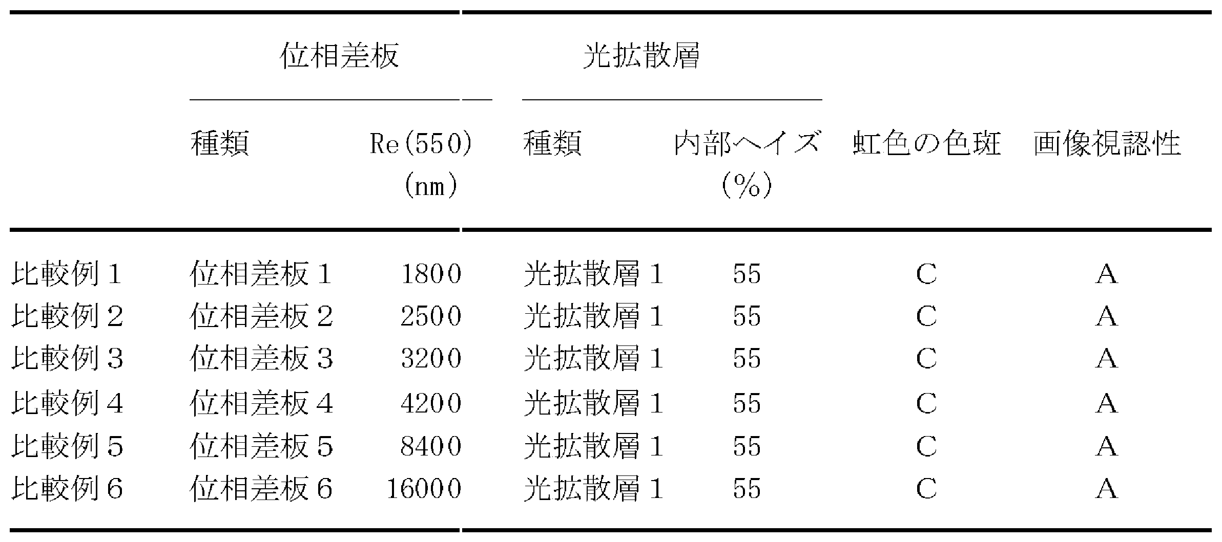


10 偏光板積層体、11 直線偏光板、12 位相差板、13 光拡散層、30 液晶積層体、31 基材層、32 配向層、33 液晶層。
Claims (10)
- 直線偏光板と、位相差板と、光拡散層とをこの順に備え、
前記直線偏光板の吸収軸と前記位相差板の遅相軸とは非平行であり、かつ非直交であって、
前記位相差板の測定波長550nmでの面内位相差値Re(550)が3000nm以上であり、
前記光拡散層の内部ヘイズが60%以上である、偏光板積層体。 - 前記位相差板の測定波長550nmでの面内位相差値Re(550)が50000nm以下である、請求項1に記載の偏光板積層体。
- 前記光拡散層の内部ヘイズが90%以下である、請求項1または2に記載の偏光板積層体。
- 前記直線偏光板の前記位相差板と反対側の面上に積層される粘着剤層をさらに備える、請求項1~3のいずれか1項に記載の偏光板積層体。
- 前記光拡散層の前記位相差板と反対側の面上に積層される前面板をさらに備える、請求項1~4のいずれか1項に記載の偏光板積層体。
- 画像形成素子と、
前記画像形成素子の視認側に配置される請求項1~5のいずれか1項に記載の偏光板積層体とを備え、
前記偏光板積層体は、前記光拡散層が前記直線偏光板よりも視認側に位置する向きで配置される、画像表示装置。 - 前記画像形成素子は、液晶セルまたは有機EL素子である、請求項6に記載の画像表示装置。
- 位相差板と、光拡散層とをこの順に備え、
前記位相差板の測定波長550nmでの面内位相差値Re(550)が3000nm以上であり、
前記光拡散層の内部ヘイズ値が60%以上である、位相差板積層体。 - 直線偏光からなる画像光を出射する画像表示パネルと、
前記画像表示パネルの視認側に配置される請求項8に記載の位相差板積層体とを備え、
前記位相差板積層体は、前記光拡散層が前記位相差板よりも視認側に位置する向きで配置される、画像表示装置。 - 前記画像表示パネルは、画像形成素子を備える、請求項9に記載の画像表示装置。
Applications Claiming Priority (4)
| Application Number | Priority Date | Filing Date | Title |
|---|---|---|---|
| JP2018-219448 | 2018-11-22 | ||
| JP2018219448 | 2018-11-22 | ||
| JP2019063538A JP2020091463A (ja) | 2018-11-22 | 2019-03-28 | 偏光板積層体 |
| JP2019-063538 | 2019-03-28 |
Publications (1)
| Publication Number | Publication Date |
|---|---|
| WO2020105327A1 true WO2020105327A1 (ja) | 2020-05-28 |
Family
ID=70773969
Family Applications (1)
| Application Number | Title | Priority Date | Filing Date |
|---|---|---|---|
| PCT/JP2019/040857 Ceased WO2020105327A1 (ja) | 2018-11-22 | 2019-10-17 | 偏光板積層体 |
Country Status (1)
| Country | Link |
|---|---|
| WO (1) | WO2020105327A1 (ja) |
Cited By (1)
| Publication number | Priority date | Publication date | Assignee | Title |
|---|---|---|---|---|
| WO2022047945A1 (zh) * | 2020-09-07 | 2022-03-10 | Tcl华星光电技术有限公司 | 显示面板 |
Citations (4)
| Publication number | Priority date | Publication date | Assignee | Title |
|---|---|---|---|---|
| JP2009036818A (ja) * | 2007-07-31 | 2009-02-19 | Konica Minolta Opto Inc | 防眩性フィルム、防眩性反射防止フィルム、偏光板および画像表示装置 |
| JP2011039228A (ja) * | 2009-08-10 | 2011-02-24 | Sumitomo Chemical Co Ltd | 複合偏光板およびtnモード液晶パネル |
| JP2018013774A (ja) * | 2016-07-08 | 2018-01-25 | 日東電工株式会社 | 光学部材及び液晶表示装置 |
| JP2018060060A (ja) * | 2016-10-05 | 2018-04-12 | 株式会社サンリッツ | 偏光板および液晶表示装置 |
-
2019
- 2019-10-17 WO PCT/JP2019/040857 patent/WO2020105327A1/ja not_active Ceased
Patent Citations (4)
| Publication number | Priority date | Publication date | Assignee | Title |
|---|---|---|---|---|
| JP2009036818A (ja) * | 2007-07-31 | 2009-02-19 | Konica Minolta Opto Inc | 防眩性フィルム、防眩性反射防止フィルム、偏光板および画像表示装置 |
| JP2011039228A (ja) * | 2009-08-10 | 2011-02-24 | Sumitomo Chemical Co Ltd | 複合偏光板およびtnモード液晶パネル |
| JP2018013774A (ja) * | 2016-07-08 | 2018-01-25 | 日東電工株式会社 | 光学部材及び液晶表示装置 |
| JP2018060060A (ja) * | 2016-10-05 | 2018-04-12 | 株式会社サンリッツ | 偏光板および液晶表示装置 |
Cited By (2)
| Publication number | Priority date | Publication date | Assignee | Title |
|---|---|---|---|---|
| WO2022047945A1 (zh) * | 2020-09-07 | 2022-03-10 | Tcl华星光电技术有限公司 | 显示面板 |
| US11709389B2 (en) | 2020-09-07 | 2023-07-25 | Tcl China Star Optoelectronics Technology Co., Ltd. | Display panel |
Similar Documents
| Publication | Publication Date | Title |
|---|---|---|
| US9740044B2 (en) | Set of polarizing plates having a young's modulus and front-plate-integrated liquid crystal display panel comprising the same | |
| CN106415339B (zh) | 光学层叠体及图像显示装置 | |
| US20160252660A1 (en) | Polarizing plate | |
| JP6690907B2 (ja) | 光学積層体、複合偏光板及び液晶表示装置 | |
| CN110208890A (zh) | 圆偏振板 | |
| KR101727870B1 (ko) | 편광판의 셋트 및 전면판 일체형 액정 표시 패널 | |
| KR102891809B1 (ko) | 원편광판 및 표시 장치 | |
| KR101757062B1 (ko) | 편광판 및 액정 표시 장치 | |
| CN110632693B (zh) | 层叠体 | |
| JP7533719B2 (ja) | 偏光板 | |
| TW201634260A (zh) | 偏光板、液晶面板及液晶顯示裝置 | |
| JP2020101815A (ja) | 偏光板セット | |
| KR20190086571A (ko) | 편광판의 제조 방법 | |
| KR20170021755A (ko) | 곡면 화상 표시 패널용 볼록면측 편광판 | |
| CN111465657A (zh) | 固化性组合物、光学层叠体及图像显示装置 | |
| JP2020091463A (ja) | 偏光板積層体 | |
| JP2009157343A (ja) | 偏光板およびそれを用いた液晶表示装置 | |
| KR20170021754A (ko) | 곡면 화상 표시 패널용 편광판 | |
| WO2020105327A1 (ja) | 偏光板積層体 | |
| CN111479876A (zh) | 固化性组合物、光学层叠体及图像显示装置 | |
| TW202321742A (zh) | 光學積層體及圖像顯示裝置 | |
| JP2021060607A (ja) | 積層体 | |
| JP7451922B2 (ja) | 自発光型画像表示装置 | |
| JP2022191315A (ja) | 円偏光板 | |
| TW202232150A (zh) | 積層直線偏光板 |
Legal Events
| Date | Code | Title | Description |
|---|---|---|---|
| 121 | Ep: the epo has been informed by wipo that ep was designated in this application |
Ref document number: 19887533 Country of ref document: EP Kind code of ref document: A1 |
|
| NENP | Non-entry into the national phase |
Ref country code: DE |
|
| 122 | Ep: pct application non-entry in european phase |
Ref document number: 19887533 Country of ref document: EP Kind code of ref document: A1 |