WO2020105232A1 - 測定結果受信装置および測定装置ならびにこれらの方法、プログラムおよび記録媒体 - Google Patents
測定結果受信装置および測定装置ならびにこれらの方法、プログラムおよび記録媒体Info
- Publication number
- WO2020105232A1 WO2020105232A1 PCT/JP2019/031223 JP2019031223W WO2020105232A1 WO 2020105232 A1 WO2020105232 A1 WO 2020105232A1 JP 2019031223 W JP2019031223 W JP 2019031223W WO 2020105232 A1 WO2020105232 A1 WO 2020105232A1
- Authority
- WO
- WIPO (PCT)
- Prior art keywords
- measurement
- measurement result
- receiving
- sampling interval
- unit
- Prior art date
- Legal status (The legal status is an assumption and is not a legal conclusion. Google has not performed a legal analysis and makes no representation as to the accuracy of the status listed.)
- Ceased
Links
Images




Classifications
-
- G—PHYSICS
- G08—SIGNALLING
- G08C—TRANSMISSION SYSTEMS FOR MEASURED VALUES, CONTROL OR SIMILAR SIGNALS
- G08C17/00—Arrangements for transmitting signals characterised by the use of a wireless electrical link
- G08C17/02—Arrangements for transmitting signals characterised by the use of a wireless electrical link using a radio link
-
- G—PHYSICS
- G01—MEASURING; TESTING
- G01D—MEASURING NOT SPECIALLY ADAPTED FOR A SPECIFIC VARIABLE; ARRANGEMENTS FOR MEASURING TWO OR MORE VARIABLES NOT COVERED IN A SINGLE OTHER SUBCLASS; TARIFF METERING APPARATUS; MEASURING OR TESTING NOT OTHERWISE PROVIDED FOR
- G01D9/00—Recording measured values
-
- G—PHYSICS
- G08—SIGNALLING
- G08C—TRANSMISSION SYSTEMS FOR MEASURED VALUES, CONTROL OR SIMILAR SIGNALS
- G08C15/00—Arrangements characterised by the use of multiplexing for the transmission of a plurality of signals over a common path
-
- G—PHYSICS
- G08—SIGNALLING
- G08C—TRANSMISSION SYSTEMS FOR MEASURED VALUES, CONTROL OR SIMILAR SIGNALS
- G08C17/00—Arrangements for transmitting signals characterised by the use of a wireless electrical link
-
- H—ELECTRICITY
- H04—ELECTRIC COMMUNICATION TECHNIQUE
- H04J—MULTIPLEX COMMUNICATION
- H04J3/00—Time-division multiplex systems
- H04J3/02—Details
- H04J3/06—Synchronising arrangements
-
- H—ELECTRICITY
- H04—ELECTRIC COMMUNICATION TECHNIQUE
- H04W—WIRELESS COMMUNICATION NETWORKS
- H04W24/00—Supervisory, monitoring or testing arrangements
- H04W24/10—Scheduling measurement reports ; Arrangements for measurement reports
-
- H—ELECTRICITY
- H04—ELECTRIC COMMUNICATION TECHNIQUE
- H04W—WIRELESS COMMUNICATION NETWORKS
- H04W56/00—Synchronisation arrangements
- H04W56/0035—Synchronisation arrangements detecting errors in frequency or phase
Definitions
- the present invention relates to processing of measurement results received from a plurality of measuring instruments.
- a measurement result receiving apparatus is a measurement result receiving apparatus that performs measurement at predetermined sampling intervals according to respective reference clocks and receives the measurement results from a plurality of measuring instruments that transmit the measurement results. And a sampling interval conversion unit that converts the measurement result into a measurement value associated with a common sampling interval.
- the measurement result receiving device configured as described above performs measurement at a predetermined sampling interval according to each reference clock, and receives the measurement result from a plurality of measuring instruments that transmit the measurement result.
- a receiving unit receives the measurement result from the plurality of measuring devices.
- a sampling interval conversion unit converts the measurement result into a measurement value associated with a common sampling interval.
- the measurement result receiving apparatus to the plurality of measuring instruments, a transmission unit that transmits a measurement start signal indicating the start of measurement and a predetermined time elapsed signal indicating that a predetermined time has elapsed from the start of the measurement. It may be provided.
- the receiving unit may perform faster communication than the transmitting unit.
- the sampling interval conversion unit based on the predetermined time and the number of the measurement results received from each of the plurality of measuring devices, each of the plurality of measuring devices.
- the sampling interval deriving unit for deriving the sampling interval in 1) and the measurement value deriving unit for deriving the measurement value based on the measurement result and the derived sampling interval may be provided.
- the measurement value derivation unit may derive the measurement value by interpolating the measurement result.
- the measurement result is any two or more of temperature, humidity, voltage, current, resistance, strain, speed, acceleration, rotation, magnetic field, position, altitude, pressure, and illuminance. May be included.
- the wireless data logger may include the measurement result receiving device according to the present invention.
- a measuring device includes a reference clock, a measuring unit that performs measurement at a predetermined sampling interval according to the reference clock, a measurement result transmitting unit that transmits a measurement result by the measuring unit, and a measurement start signal indicating measurement start. And a control signal receiving unit that receives a predetermined time elapsed signal indicating that a predetermined time has elapsed from the start of the measurement, and the measurement result transmitting unit performs faster communication than the control signal receiving unit. Is composed of.
- the measuring device there is a reference clock.
- the measuring unit measures at a predetermined sampling interval according to the reference clock.
- the measurement result transmission unit transmits the measurement result by the measurement unit.
- the control signal receiving unit receives a measurement start signal indicating the start of measurement and a predetermined time elapsed signal indicating that a predetermined time has elapsed from the start of the measurement.
- the measurement result transmitting unit performs faster communication than the control signal receiving unit.
- the measurement result includes any two or more of temperature, humidity, voltage, current, resistance, strain, speed, acceleration, rotation, magnetic field, position, altitude, pressure, and illuminance. You may leave it.
- the wireless data logger may be equipped with the measuring device according to the present invention.
- the present invention is a measurement result receiving method for performing measurement at a predetermined sampling interval according to each reference clock, and receiving the measurement result from a plurality of measurement devices transmitting the measurement result, wherein the measurement is performed from the plurality of measurement devices.
- the measurement result receiving method includes a receiving step of receiving a result and a sampling interval converting step of converting the measurement result into a measurement value associated with a common sampling interval.
- the present invention is a program for performing a measurement result receiving process of performing measurement at a predetermined sampling interval according to each reference clock and receiving the measurement result from a plurality of measuring instruments that transmit the measurement result,
- the measurement result receiving process includes a receiving step of receiving the measurement results from the plurality of measuring devices, and a sampling interval conversion step of converting the measurement results into a measurement value associated with a common sampling interval. It is a program.
- the present invention is a computer recording a program for causing a computer to perform a measurement result receiving process of performing measurement at a predetermined sampling interval according to each reference clock and receiving the measurement result from a plurality of measuring instruments transmitting the measurement result.
- the present invention shows a reference clock generation step of generating a reference clock, a measurement step of performing measurement at a predetermined sampling interval according to the reference clock, a measurement result transmission step of transmitting a measurement result of the measurement step, and a measurement start.
- the present invention shows a reference clock generation step of generating a reference clock, a measurement step of performing measurement at a predetermined sampling interval according to the reference clock, a measurement result transmission step of transmitting a measurement result of the measurement step, and a measurement start.
- a control signal receiving step of receiving a measurement start signal and a predetermined time elapsed signal indicating that a predetermined time has elapsed from the start of the measurement, wherein the measurement result transmitting step is faster than the control signal receiving step. It is a program for causing a computer to execute a measurement process for performing.
- the present invention shows a reference clock generation step of generating a reference clock, a measurement step of performing measurement at a predetermined sampling interval according to the reference clock, a measurement result transmission step of transmitting a measurement result of the measurement step, and a measurement start.
- a control signal receiving step of receiving a measurement start signal and a predetermined time elapsed signal indicating that a predetermined time has elapsed from the start of the measurement, wherein the measurement result transmitting step is faster than the control signal receiving step.
- It is a computer-readable recording medium in which a program for causing a computer to execute the measurement processing for performing is recorded.
- FIG. 6 is a graph showing the measurement results when the measurement target amount from the start of measurement to a predetermined time T is measured at a predetermined sampling interval according to each reference clock 2d of the measuring device 2, and when the sampling interval is correct (FIG. (A)), the sampling interval is too short (FIG. 5 (b)), and the sampling interval is too long (FIG. 5 (c)).
- FIG. 6 is a graph for explaining conversion of measurement results into measurement values associated with a common sampling interval, where the sampling interval is correct (FIG. 6A) and the sampling interval is too short (FIG. b)) shows the case where the sampling interval is too long (FIG. 6 (c)).
- FIG. 1 is a diagram showing a configuration of a wireless communication system according to an embodiment of the present invention.
- the wireless communication system according to the embodiment of the present invention includes a measurement result receiving device 1 and a plurality of measuring devices 2.
- the measuring device 2 may measure the voltage, temperature or strain (other than humidity, current, resistance, velocity, acceleration, rotation, magnetic field, position, altitude, etc.) of an object to be measured (for example, but not limited to an automobile or a semiconductor). Pressure or illuminance may be measured), and the measurement result is wirelessly transmitted to the measurement result receiving device 1.
- the measurement result may be any two or more of voltage, temperature, strain, humidity, current, resistance, speed, acceleration, rotation, magnetic field, position, altitude, pressure, and illuminance.
- the plurality of measuring devices 2 perform measurement at a predetermined sampling interval (for example, 1 ms) according to each reference clock (for example, 1 kHz).
- the measurement result receiving device 1 wirelessly receives the measurement result transmitted from the measuring device 2. Further, the measurement result receiving device 1 wirelessly transmits a control signal for controlling the measurement to the measuring device 2.
- the control signal is, for example, a measurement start signal indicating the start of measurement, a predetermined time elapsed signal indicating that a predetermined time T (for example, 2 seconds) has elapsed from the start of measurement, and instructs the measuring device 2 to transmit the measurement result. It includes a transmission instruction signal.
- the measurement result receiving device 1 is configured such that, for example, a router for wireless communication (for high speed communication) is connected to a normal personal computer by wire, and a wireless LAN unit (for low speed communication) is connected to a USB port of the normal personal computer. ) Is connected.
- sending and receiving measurement results is faster than sending and receiving control signals.
- the transmission and reception of the measurement result is performed by WiFi, for example.
- FIG. 2 is a functional block diagram showing the configuration of the measuring device 2 according to the embodiment of the present invention.
- the measuring device 2 according to the embodiment of the present invention includes a low speed receiving unit (control signal receiving unit) 2a, a control signal extracting unit 2b, a measuring unit 2c, a reference clock 2d, a measurement result transmitting unit 2e, and a high speed transmitting unit (measurement result transmitting unit). Part) 2f.
- the low-speed receiving unit (control signal receiving unit) 2a receives a control signal (for example, the above-mentioned measurement start signal, predetermined time elapsed signal, and predetermined time elapsed signal).
- a control signal for example, the above-mentioned measurement start signal, predetermined time elapsed signal, and predetermined time elapsed signal.
- the control signal extraction unit 2b extracts the control signal from the low speed reception unit 2a and transmits it to the measurement unit 2c.
- the measurement unit 2c measures according to the control signal. For example, the measurement unit 2c starts the measurement when receiving the measurement start signal. When the measurement unit 2c receives the predetermined time elapsed signal, the measurement unit 2c collects the measurement results from the start of measurement to the reception of the predetermined time elapsed signal in a transmittable state. When the measurement unit 2c receives the transmission instruction signal, the measurement unit 2c provides the measurement result transmission unit 2e with the measurement results from the start of measurement until the reception of the signal for the predetermined time.
- the reference clock 2d gives a reference clock signal to the measuring unit 2c.
- the measuring unit 2c measures at a predetermined sampling interval.
- the frequency of the reference clock signal should be the same in all measuring devices 2 (1 kHz, for example), but a slight error occurs.
- the measurement result transmission unit 2e gives the measurement result received from the measurement unit 2c to the high speed transmission unit 2f.
- the high-speed transmission unit (measurement result transmission unit) 2f transmits the measurement result obtained by the measurement unit 2c to the measurement result reception device 1.
- the high speed transmission unit 2f performs higher speed communication than the low speed reception unit 2a.
- the transmission of the high-speed transmission unit 2f is performed by WiFi, for example.
- the high-speed transmission unit 2f may receive information regarding the measurement result from the measurement result receiving device 1. Further, the low-speed receiving unit 2a may transmit information regarding the control signal to the measurement result receiving device 1.
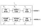
- FIG. 3 is a functional block diagram showing the configuration of the measurement result receiving device 1 according to the embodiment of the present invention.
- the measurement result receiving apparatus 1 includes a control signal source 1a, a control signal transmitting unit 1b, a low speed transmitting unit 1c, a high speed receiving unit 1d, a measurement result extracting unit 1e, and a measurement result processing unit 1f.
- the control signal source 1a outputs a control signal (for example, the above-described measurement start signal, predetermined time elapsed signal, and predetermined time elapsed signal).
- a control signal for example, the above-described measurement start signal, predetermined time elapsed signal, and predetermined time elapsed signal.
- the control signal transmission unit 1b receives the control signal from the control signal source 1a and transmits it to the low speed transmission unit 1c.
- the low-speed transmitter 1c transmits a control signal to the plurality of measuring instruments 2.
- the high-speed receiver 1d receives the measurement results from the plurality of measuring devices 2.
- the high-speed receiving unit 1d performs higher-speed communication than the low-speed transmitting unit 1c.
- the reception of the high-speed receiving unit 1d is performed by WiFi, for example.
- the measurement result extraction unit 1e extracts the measurement result from the content received by the high-speed reception unit 1d.
- the measurement result processing unit 1f receives the measurement result from the measurement result extracting unit 1e and processes the measurement result.
- the high-speed receiving unit 1d may send information about the measurement result to the measuring device 2. Further, the low-speed transmission unit 1c may receive information regarding the control signal from the measuring device 2.
- FIG. 4 is a functional block diagram showing the configuration of the measurement result processing unit 1f according to the embodiment of the present invention.
- the measurement result processing unit 1f according to the embodiment of the present invention includes a measurement number extraction unit 1f-1, a sampling interval derivation unit 1f-2, a time characteristic extraction unit 1f-4, and a synchronization unit (measurement value derivation unit) 1f-6.
- the sampling interval deriving unit 1f-2 and the synchronization unit (measurement value deriving unit) 1f-6 correspond to the sampling interval converting unit.
- the time characteristic extraction unit 1f-4 extracts the characteristic of the measurement result with respect to time (that is, the time characteristic) from the measurement result and supplies it to the synchronization unit 1f-6.
- the measurement frequency extraction unit 1f-1 extracts the number of times of measurement from the measurement result in the measurement result from the start of measurement until the reception of a signal for a predetermined time, and supplies it to the sampling interval derivation unit 1f-2.
- the predetermined time T is 2 seconds and the original value of the frequency of the reference clock is 1 kHz
- the sampling interval is too short
- the sampling interval is too short.
- the sampling interval deriving unit 1f-2 and the synchronizing unit 1f-6 convert the measurement result into a measurement value associated with a common sampling interval.
- the sampling interval deriving unit 1f-2 determines a plurality of times based on the predetermined time T and the numbers Na, Nb, and Nc of measurement results received from each of the plurality of measuring devices 2 (received from the measurement number extracting unit 1f-1). The sampling interval in each of the measuring devices 2 is derived.
- FIG. 5 is a graph showing the measurement results when the measurement target amount from the start of measurement to a predetermined time T is measured at a predetermined sampling interval according to each reference clock 2d of the measuring instrument 2, and the sampling interval is correct.
- the sampling interval is too short (FIG. 5B), and the sampling interval is too long (FIG. 5C).
- FIG. 5 it is assumed that each of the measuring devices 2 measures a common measurement target.
- the sampling interval is set to tb. Then, the measurement results are obtained for the times tb, 2tb, 3tb, ... And the time when the measurement results are obtained is shifted earlier than when the sampling interval is correct. If, in such a situation, it is assumed that the measurement result is obtained for the time 1, 2, 3, ... ms, it will be an erroneous measurement. Therefore, it is necessary to match the measurement results obtained for the times tb, 2tb, 3tb, ... With the measurement results obtained for the times ta, 2ta, 3ta ,.
- the sampling interval is set to tc. Then, the measurement result is obtained for the time tc, 2tc, 3tc, ... And the time when the measurement result is obtained is shifted later than when the sampling interval is correct. If, in such a situation, it is assumed that the measurement result is obtained for the time 1, 2, 3, ... ms, it will be an erroneous measurement. Therefore, it is necessary to match the measurement results obtained for the times tc, 2tc, 3tc, ... With the measurement results obtained for the times ta, 2ta, 3ta ,.
- FIG. 6 is a graph for explaining the conversion of the measurement result into a measurement value associated with a common sampling interval.
- FIG. 6A When the sampling interval is correct (FIG. 6A), when the sampling interval is too short. (FIG. 6B) shows a case where the sampling interval is too long (FIG. 6C).
- the measurement result will be the measurement value as it is.
- interpolation is not limited to linear interpolation, and other interpolations (for example, least squares method) may be used.
- the control signal source 1a of the measurement result receiving device 1 outputs a measurement start signal.
- the measurement start signal is transmitted from the low-speed transmission unit 1c to the plurality of measuring devices 2.
- the measuring device 2 receives the measurement start signal by the low-speed receiving unit 2a.
- the measuring unit 2c starts the measurement.
- the measurement is performed at predetermined sampling intervals according to the reference clock signal output by the reference clock 2d. However, a slight error occurs in each reference clock 2d, and the sampling interval is too short (see FIG. 5B) or too long (see FIG. 5C).
- the control signal source 1a of the measurement result receiving device 1 outputs a signal for a predetermined time.
- the predetermined time elapsed signal is transmitted from the low speed transmission unit 1c to the plurality of measuring devices 2.
- the measurement unit 2c of the measuring device 2 receives the signal for the predetermined time, the measurement result from the start of measurement to the reception of the signal for the predetermined time (measurement result from time 0 to T: see FIG. 5) is ready for transmission. Put together.
- control signal source 1a of the measurement result receiving device 1 outputs a transmission instruction signal.
- the transmission instruction signal is transmitted from the low-speed transmission unit 1c to the plurality of measuring devices 2.
- the measuring unit 2c of the measuring instrument 2 Upon receiving the transmission instruction signal, the measuring unit 2c of the measuring instrument 2 sends the measurement result from the start of measurement until the reception of the signal for a predetermined time (measurement result from time 0 to T: see FIG. 5) to the measurement result transmitting unit 2e. give.
- the measurement result is transmitted from the high speed transmission unit 2f to the measurement result receiving device 1.
- the measurement result of each measuring device 2 is received by the high-speed receiving unit 1d and processed by the measurement result processing unit 1f.
- the measurement number extraction unit 1f-1 extracts the number of times of measurement (Na, Nb, Nc) in the measurement result (measurement result of time 0 to T) from the measurement result.
- the synchronization unit 1f-6 receives the sampling intervals ta, tb, and tc from the sampling interval deriving unit 1f-2, receives the time characteristic from the time characteristic extracting unit 1f-4, and measures the measurement values associated with the common sampling interval ta. Is derived (see FIG. 6).
- linear interpolation is performed between the measurement result at time Ntc and the measurement result at time (N + 1) tc, so that at time (N + 1) ta, Derive the measured value (illustrated by ⁇ ).
- each measurement result of the measuring device 2 is converted into a measurement value at the sampling interval ta. By aligning them, the measurement results of the measuring instruments 2 can be synchronized.
- the transmission / reception of the measurement result is faster than the transmission / reception of the control signal. Therefore, a large-volume measurement result can be received and processed by the measurement result receiving device 1.
- the measurement result receiving device 1 and the measurement device 2 form a wireless data logger.
- the above embodiment can be realized as follows.
- a program for realizing each of the above-mentioned parts for example, each part of the measurement result receiving device 1 or each part of the measuring instrument 2 is recorded. Read the media and install it on the hard disk. Even with such a method, the above function can be realized.
Landscapes
- Engineering & Computer Science (AREA)
- Computer Networks & Wireless Communication (AREA)
- Physics & Mathematics (AREA)
- General Physics & Mathematics (AREA)
- Signal Processing (AREA)
- Arrangements For Transmission Of Measured Signals (AREA)
- Recording Measured Values (AREA)
Abstract
【課題】測定器の各々が有する基準クロックの周波数に誤差が生じた場合であっても、測定器の各々の測定結果の同期をとる。 【解決手段】測定結果受信装置1が、各々の基準クロック2dに従って所定のサンプリング間隔ta、tb、tcで測定を行い、測定結果を送信する複数の測定器2から測定結果を受信する。測定結果受信装置1は、複数の測定器2から測定結果を受信する受信部1dと、測定結果を、共通のサンプリング間隔taに対応づけられた測定値に変換するサンプリング間隔変換部1f-2、1f-6とを備える。
Description
本発明は、複数の測定器から受信した測定結果の処理に関する。
従来より、複数の測定器から測定結果を無線により受信して処理することが知られている(例えば、特許文献1の要約を参照)。複数の測定器は各々が有する基準クロックにしたがい所定のサンプリング間隔ごとに測定を行う。
しかしながら、上記のような従来技術によれば、測定器の各々が有する基準クロックの周波数に誤差が生じた場合、測定器の各々の測定結果の同期をとることができない。
そこで、本発明は、測定器の各々が有する基準クロックの周波数に誤差が生じた場合であっても、測定器の各々の測定結果の同期をとることを課題とする。
本発明にかかる測定結果受信装置は、各々の基準クロックに従って所定のサンプリング間隔で測定を行い、測定結果を送信する複数の測定器から該測定結果を受信する測定結果受信装置であって、前記複数の測定器から前記測定結果を受信する受信部と、前記測定結果を、共通のサンプリング間隔に対応づけられた測定値に変換するサンプリング間隔変換部とを備えるように構成される。
上記のように構成された測定結果受信装置は、各々の基準クロックに従って所定のサンプリング間隔で測定を行い、測定結果を送信する複数の測定器から該測定結果を受信する。受信部が、前記複数の測定器から前記測定結果を受信する。サンプリング間隔変換部が、前記測定結果を、共通のサンプリング間隔に対応づけられた測定値に変換する。
なお、本発明にかかる測定結果受信装置は、前記複数の測定器へ、測定開始を示す測定開始信号と、該測定開始から所定時間経過したことを示す所定時間経過信号とを送信する送信部を備えるようにしてもよい。
なお、本発明にかかる測定結果受信装置は、前記受信部が、前記送信部よりも、高速な通信を行うようにしてもよい。
なお、本発明にかかる測定結果受信装置は、前記サンプリング間隔変換部が、前記所定時間と、前記複数の測定器の各々から受信した前記測定結果の個数とに基づき、前記複数の測定器の各々におけるサンプリング間隔を導出するサンプリング間隔導出部と、前記測定結果と導出されたサンプリング間隔とに基づき、前記測定値を導出する測定値導出部とを有するようにしてもよい。
なお、本発明にかかる測定結果受信装置は、前記測定値導出部が、前記測定結果を補間することにより、前記測定値を導出するようにしてもよい。
なお、本発明にかかる測定結果受信装置は、前記測定結果が、温度、湿度、電圧、電流、抵抗、歪み、速度、加速度、回転、磁界、位置、高度、圧力、照度のいずれか2つ以上を含むようにしてもよい。
なお、本発明にかかる測定結果受信装置を無線データロガーが備えるようにしてもよい。
本発明にかかる測定装置は、基準クロックと、該基準クロックに従って所定のサンプリング間隔で測定を行う測定部と、該測定部による測定結果を送信する測定結果送信部と、測定開始を示す測定開始信号と、該測定開始から所定時間経過したことを示す所定時間経過信号とを受信する制御信号受信部とを備え、前記測定結果送信部が、前記制御信号受信部よりも、高速な通信を行うように構成される。
上記のように構成された測定装置によれば、基準クロックがある。測定部が、該基準クロックに従って所定のサンプリング間隔で測定を行う。測定結果送信部が、該測定部による測定結果を送信する。制御信号受信部が、測定開始を示す測定開始信号と、該測定開始から所定時間経過したことを示す所定時間経過信号とを受信する。前記測定結果送信部が、前記制御信号受信部よりも、高速な通信を行う。
なお、本発明にかかる測定装置は、前記測定結果が、温度、湿度、電圧、電流、抵抗、歪み、速度、加速度、回転、磁界、位置、高度、圧力、照度のいずれか2つ以上を含むようにしてもよい。
なお、本発明にかかる測定装置を無線データロガーが備えるようにしてもよい。
本発明は、各々の基準クロックに従って所定のサンプリング間隔で測定を行い、測定結果を送信する複数の測定器から該測定結果を受信する測定結果受信方法であって、前記複数の測定器から前記測定結果を受信する受信工程と、前記測定結果を、共通のサンプリング間隔に対応づけられた測定値に変換するサンプリング間隔変換工程とを備えた測定結果受信方法である。
本発明は、各々の基準クロックに従って所定のサンプリング間隔で測定を行い、測定結果を送信する複数の測定器から該測定結果を受信する測定結果受信処理をコンピュータに実行させるためのプログラムであって、前記測定結果受信処理が、前記複数の測定器から前記測定結果を受信する受信工程と、前記測定結果を、共通のサンプリング間隔に対応づけられた測定値に変換するサンプリング間隔変換工程とを備えたプログラムである。
本発明は、各々の基準クロックに従って所定のサンプリング間隔で測定を行い、測定結果を送信する複数の測定器から該測定結果を受信する測定結果受信処理をコンピュータに実行させるためのプログラムを記録したコンピュータによって読み取り可能な記録媒体であって、前記測定結果受信処理が、前記複数の測定器から前記測定結果を受信する受信工程と、前記測定結果を、共通のサンプリング間隔に対応づけられた測定値に変換するサンプリング間隔変換工程とを備えた記録媒体である。
本発明は、基準クロックを生成する基準クロック生成工程と、該基準クロックに従って所定のサンプリング間隔で測定を行う測定工程と、該測定工程による測定結果を送信する測定結果送信工程と、測定開始を示す測定開始信号と、該測定開始から所定時間経過したことを示す所定時間経過信号とを受信する制御信号受信工程とを備え、前記測定結果送信工程が、前記制御信号受信工程よりも、高速な通信を行う測定方法である。
本発明は、基準クロックを生成する基準クロック生成工程と、該基準クロックに従って所定のサンプリング間隔で測定を行う測定工程と、該測定工程による測定結果を送信する測定結果送信工程と、測定開始を示す測定開始信号と、該測定開始から所定時間経過したことを示す所定時間経過信号とを受信する制御信号受信工程とを備え、前記測定結果送信工程が、前記制御信号受信工程よりも、高速な通信を行う測定処理をコンピュータに実行させるためのプログラムである。
本発明は、基準クロックを生成する基準クロック生成工程と、該基準クロックに従って所定のサンプリング間隔で測定を行う測定工程と、該測定工程による測定結果を送信する測定結果送信工程と、測定開始を示す測定開始信号と、該測定開始から所定時間経過したことを示す所定時間経過信号とを受信する制御信号受信工程とを備え、前記測定結果送信工程が、前記制御信号受信工程よりも、高速な通信を行う測定処理をコンピュータに実行させるためのプログラムを記録したコンピュータによって読み取り可能な記録媒体である。
以下、本発明の実施形態を図面を参照しながら説明する。
図1は、本発明の実施形態にかかる無線通信システムの構成を示す図である。本発明の実施形態にかかる無線通信システムは、測定結果受信装置1および複数の測定器2を備える。
測定器2は、測定対象(例えば、自動車または半導体であるが、それに限定されない)の電圧、温度または歪み(他にも、湿度、電流、抵抗、速度、加速度、回転、磁界、位置、高度、圧力、照度でもよい)を測定し、その測定結果を測定結果受信装置1に無線により送信する。なお、測定結果は、電圧、温度、歪み、湿度、電流、抵抗、速度、加速度、回転、磁界、位置、高度、圧力、照度のいずれか2つ以上であってもよい。複数の測定器2は、各々の基準クロック(例えば、1kHz)に従って所定のサンプリング間隔(例えば、1ms)で測定を行う。
測定結果受信装置1は、測定器2から送信された測定結果を無線により受信する。また、測定結果受信装置1は、測定器2へ、測定を制御するための制御信号を無線により送信する。制御信号は、例えば、測定開始を示す測定開始信号と、測定の開始から所定時間T(例えば、2秒)経過したことを示す所定時間経過信号と、測定器2に測定結果の送信を指示する送信指示信号を含む。
なお、測定結果受信装置1は、例えば、通常のパーソナルコンピュータに無線通信用のルータ(高速通信用)を有線により接続し、さらに、その通常のパーソナルコンピュータのUSBポートに無線LANユニット(低速通信用)を接続したものである。
なお、測定結果の送受信は、制御信号の送受信よりも、高速である。測定結果の送受信は、例えば、WiFiにより行われる。
図2は、本発明の実施形態にかかる測定器2の構成を示す機能ブロック図である。本発明の実施形態にかかる測定器2は、低速受信部(制御信号受信部)2a、制御信号抽出部2b、測定部2c、基準クロック2d、測定結果伝達部2e、高速送信部(測定結果送信部)2fを備える。
低速受信部(制御信号受信部)2aは、制御信号(例えば、上述の測定開始信号、所定時間経過信号および所定時間経過信号)を受信する。
制御信号抽出部2bは、低速受信部2aから、制御信号を抽出して、測定部2cへ伝達する。
測定部2cは、制御信号に即して、測定を行う。例えば、測定部2cは、測定開始信号を受けると、測定を開始する。測定部2cは、所定時間経過信号を受けると、測定開始から所定時間経過信号を受けるまでの測定結果を、送信可能な状態にまとめる。測定部2cは、送信指示信号を受けると、測定開始から所定時間経過信号を受けるまでの測定結果を、測定結果伝達部2eに与える。
基準クロック2dは、測定部2cに基準クロック信号を与える。この基準クロック信号に従って、測定部2cが所定のサンプリング間隔で測定を行う。なお、基準クロック信号の周波数は、本来、いずれの測定器2においても同じであるべきものであるが(例えば、1kHz)、微妙に誤差が生じる。
測定結果伝達部2eは、測定部2cから受けた測定結果を、高速送信部2fに与える。
高速送信部(測定結果送信部)2fは、測定部2cによる測定結果を、測定結果受信装置1へ送信する。高速送信部2fは、低速受信部2aよりも、高速な通信を行う。高速送信部2fの送信は、例えば、WiFiにより行われる。
なお、高速送信部2fは、測定結果に関する情報を、測定結果受信装置1から受信するようにしてもよい。また、低速受信部2aは、制御信号に関する情報を、測定結果受信装置1へ送信するようにしてもよい。
図3は、本発明の実施形態にかかる測定結果受信装置1の構成を示す機能ブロック図である。
本発明の実施形態にかかる測定結果受信装置1は、制御信号源1a、制御信号伝達部1b、低速送信部1c、高速受信部1d、測定結果抽出部1e、測定結果処理部1fを備える。
制御信号源1aは、制御信号(例えば、上述の測定開始信号、所定時間経過信号および所定時間経過信号)を出力する。
制御信号伝達部1bは、制御信号源1aから制御信号を受けて、低速送信部1cに伝達する。
低速送信部1cは、複数の測定器2へ、制御信号を送信する。
高速受信部1dは、複数の測定器2から、測定結果を受信する。なお、高速受信部1dは、低速送信部1cよりも、高速な通信を行う。高速受信部1dの受信は、例えば、WiFiにより行われる。
測定結果抽出部1eは、高速受信部1dの受信内容から、測定結果を抽出する。
測定結果処理部1fは、測定結果抽出部1eから測定結果を受け、測定結果を処理する。
なお、高速受信部1dは、測定結果に関する情報を、測定器2へ送信するようにしてもよい。また、低速送信部1cは、制御信号に関する情報を、測定器2から受信するようにしてもよい。
図4は、本発明の実施形態にかかる測定結果処理部1fの構成を示す機能ブロック図である。本発明の実施形態にかかる測定結果処理部1fは、測定回数抽出部1f-1、サンプリング間隔導出部1f-2、時間特性抽出部1f-4、同期部(測定値導出部)1f-6を有する。なお、サンプリング間隔導出部1f-2および同期部(測定値導出部)1f-6が、サンプリング間隔変換部に相当する。
時間特性抽出部1f-4は、測定結果から、時間に対する測定結果の特性(すなわち、時間特性)を抽出し、同期部1f-6に与える。
測定回数抽出部1f-1は、測定結果から、測定開始から所定時間経過信号を受けるまでの測定結果において測定が行われた回数を抽出し、サンプリング間隔導出部1f-2に与える。例えば、所定時間Tが2秒かつ基準クロックの周波数の本来の値が1kHzの場合、サンプリング間隔が正しい測定器2(測定回数Na=2000回)(サンプリング間隔=1ms)、サンプリング間隔が短すぎる測定器2(測定回数Nb>Na、例えばNb=2010回)、サンプリング間隔が長すぎる測定器2(測定回数Nc<Na、例えばNc=1995回)から測定結果を受信した場合、Na、Nb、Ncを、測定結果から抽出し、サンプリング間隔導出部1f-2に与える。
サンプリング間隔導出部1f-2および同期部1f-6は、測定結果を、共通のサンプリング間隔に対応づけられた測定値に変換する。
サンプリング間隔導出部1f-2は、所定時間Tと、複数の測定器2の各々から受信した測定結果の個数Na、Nb、Nc(測定回数抽出部1f-1から受ける)とに基づき、複数の測定器2の各々におけるサンプリング間隔を導出する。
例えば、サンプリング間隔導出部1f-2によれば、サンプリング間隔が正しい測定器2(測定回数Na)についてはT/Na(=ta=1ms)、サンプリング間隔が短すぎる測定器2(測定回数Nb)についてはT/Nb(=tb)、サンプリング間隔が長すぎる測定器2(測定回数Nc)についてはT/Nc(=tc)がサンプリング間隔として導出される。
同期部(測定値導出部)1f-6は、測定結果(から抽出された時間特性)と、サンプリング間隔導出部1f-2により導出されたサンプリング間隔T/Na(=ta=1ms)、T/Nb(=tb)、T/Nc(=tc)とに基づき、共通のサンプリング間隔に対応づけられた測定値を導出する。なお、測定結果を補間することにより、測定値を導出することができる。
測定結果の補間による測定値の導出法を以下に説明する。
図5は、測定開始から所定時間Tまでの測定対象量を、測定器2の各々の基準クロック2dに従って所定のサンプリング間隔で測定を行った場合の測定結果を示すグラフであり、サンプリング間隔が正しい場合(図5(a))、サンプリング間隔が短すぎる場合(図5(b))、サンプリング間隔が長すぎる場合(図5(c))を示す。なお、図5においては、測定器2の各々が、共通の測定対象を測定しているものと仮定している。
まず、図5(a)を参照して、サンプリング間隔が正しい場合、そのサンプリング間隔をta(=1ms)とする。すると、測定結果は、時間ta、2ta、3ta、…(すなわち、1、2、3、…ms)について得られる。
次に、図5(b)を参照して、サンプリング間隔が短すぎる場合、そのサンプリング間隔をtbとする。すると、測定結果は、時間tb、2tb、3tb、…について得られ、サンプリング間隔が正しい場合よりも、測定結果が得られる時間が前にずれる。もし、このような状況で、時間1、2、3、…msについて、測定結果が得られたとみなせば、それは誤った測定となる。そこで、時間tb、2tb、3tb、…について得られた測定結果を、時間ta、2ta、3ta、…(すなわち、1、2、3、…ms)ついて得られた測定結果にあわせる必要がある。
次に、図5(c)を参照して、サンプリング間隔が長すぎる場合、そのサンプリング間隔をtcとする。すると、測定結果は、時間tc、2tc、3tc、…について得られ、サンプリング間隔が正しい場合よりも、測定結果が得られる時間が後にずれる。もし、このような状況で、時間1、2、3、…msについて、測定結果が得られたとみなせば、それは誤った測定となる。そこで、時間tc、2tc、3tc、…について得られた測定結果を、時間ta、2ta、3ta、…(すなわち、1、2、3、…ms)ついて得られた測定結果にあわせる必要がある。
図6は、測定結果の、共通のサンプリング間隔に対応づけられた測定値への変換を説明するためのグラフであり、サンプリング間隔が正しい場合(図6(a))、サンプリング間隔が短すぎる場合(図6(b))、サンプリング間隔が長すぎる場合(図6(c))を示す。ただし、図6におけるNは、1以上T/ta(=2000)以下の整数である。
共通のサンプリング間隔としては、正しいサンプリング間隔(1ms)を使用する。
まず、サンプリング間隔が正しい場合(図6(a)参照)は、測定結果がそのまま測定値となる。
次に、サンプリング間隔が短すぎる場合(図6(b)参照)は、時間Ntbと時間(N+1)tbとの間に時間Ntaがある。よって、時間Ntbのときの測定結果と、時間(N+1)tbのときの測定結果との間で直線補間を行えば、時間Ntaのときの測定値(黒丸印●で図示)を得ることができる。なお、サンプリング間隔導出部1f-2により、tbは、T/Nbとして求めることができる。同様に、時間(N+1)tbのときの測定結果と、時間(N+2)tbのときの測定結果との間で直線補間を行えば、時間(N+1)taのときの測定値(●で図示)を得ることができる。
次に、サンプリング間隔が長すぎる場合(図6(c)参照)は、時間Ntcと時間(N+1)tcとの間に時間(N+1)taがある。よって、時間Ntcのときの測定結果と、時間(N+1)tcのときの測定結果との間で直線補間を行えば、時間(N+1)taのときの測定値(●で図示)を得ることができる。なお、サンプリング間隔導出部1f-2により、tcは、T/Ncとして求めることができる。同様に、時間(N+1)tcのときの測定結果と、時間(N+2)tcのときの測定結果との間で直線補間を行えば、時間(N+2)taのときの測定値(●で図示)を得ることができる。
ただし、補間は、直線補間に限らず、他の補間(例えば、最小二乗法など)を用いてもかまわない。
次に、本発明の実施形態の動作を説明する。
まず、測定結果受信装置1の制御信号源1aが測定開始信号を出力する。測定開始信号は、低速送信部1cから、複数の測定器2へ送信される。測定器2は、低速受信部2aにより、測定開始信号を受信する。そして、測定部2cが測定を開始する。測定は、基準クロック2dの出力する基準クロック信号に従って、所定のサンプリング間隔で行われる。ただし、各々の基準クロック2dには微妙に誤差が生じ、サンプリング間隔が短すぎたり(図5(b)参照)、長すぎたりするもの(図5(c)参照)が生じる。
次に、測定結果受信装置1の制御信号源1aが所定時間経過信号を出力する。所定時間経過信号は、低速送信部1cから、複数の測定器2へ送信される。測定器2の測定部2cは、所定時間経過信号を受けると、測定開始から所定時間経過信号を受けるまでの測定結果(時間0~Tの測定結果:図5参照)を、送信可能な状態にまとめる。
さらに、測定結果受信装置1の制御信号源1aが送信指示信号を出力する。送信指示信号は、低速送信部1cから、複数の測定器2へ送信される。測定器2の測定部2cは、送信指示信号を受けると、測定開始から所定時間経過信号を受けるまでの測定結果(時間0~Tの測定結果:図5参照)を、測定結果伝達部2eに与える。この測定結果は、高速送信部2fから測定結果受信装置1へ送信される。
各々の測定器2の測定結果は、高速受信部1dにより受信され、測定結果処理部1fにより処理される。
まず、測定回数抽出部1f-1が、測定結果から、測定結果(時間0~Tの測定結果)において測定が行われた回数(Na、Nb、Nc)を抽出する。サンプリング間隔導出部1f-2が、これらの回数(Na、Nb、Nc)および所定時間Tから、測定器2の各々におけるサンプリング間隔T/Na(=ta=1ms)、T/Nb(=tb)、T/Nc(=tc)を導出する。同期部1f-6は、サンプリング間隔導出部1f-2からサンプリング間隔ta、tb、tcを受け、時間特性抽出部1f-4から時間特性を受け、共通のサンプリング間隔taに対応づけられた測定値を導出する(図6参照)。
例えば、図6(b)を参照して、時間Ntbのときの測定結果と、時間(N+1)tbのときの測定結果との間で直線補間を行うことにより、時間Ntaのときの測定値(●で図示)を導出する。
例えば、図6(c)を参照して、時間Ntcのときの測定結果と、時間(N+1)tcのときの測定結果との間で直線補間を行うことにより、時間(N+1)taのときの測定値(●で図示)を導出する。
本発明の実施形態によれば、測定器2の各々が有する基準クロック2dの周波数に誤差が生じた場合であっても、測定器2の各々の測定結果を、サンプリング間隔taでの測定値にそろえることにより、測定器2の各々の測定結果の同期をとることができる。
さらに、本発明の実施形態によれば、測定結果の送受信は、制御信号の送受信よりも、高速である。よって、大容量の測定結果も、測定結果受信装置1により受信および処理することができる。
なお、測定結果受信装置1および測定装置2が、無線データロガーを構成する。
また、上記の実施形態は、以下のようにして実現できる。CPU、ハードディスク、メディア(USBメモリ、CD-ROMなど)読み取り装置を備えたコンピュータに、上記の各部分、例えば測定結果受信装置1の各部分または測定器2の各部分を実現するプログラムを記録したメディアを読み取らせて、ハードディスクにインストールする。このような方法でも、上記の機能を実現できる。
1 測定結果受信装置
1a 制御信号源
1b 制御信号伝達部
1c 低速送信部
1d 高速受信部
1e 測定結果抽出部
1f 測定結果処理部
1f-1 測定回数抽出部
1f-2 サンプリング間隔導出部
1f-4 時間特性抽出部
1f-6 同期部(測定値導出部)
2 測定器
2a 低速受信部(制御信号受信部)
2b 制御信号抽出部
2c 測定部
2d 基準クロック
2e 測定結果伝達部
2f 高速送信部(測定結果送信部)
Na、Nb、Nc 測定回数
ta、tb、tc サンプリング間隔
T 所定時間
1a 制御信号源
1b 制御信号伝達部
1c 低速送信部
1d 高速受信部
1e 測定結果抽出部
1f 測定結果処理部
1f-1 測定回数抽出部
1f-2 サンプリング間隔導出部
1f-4 時間特性抽出部
1f-6 同期部(測定値導出部)
2 測定器
2a 低速受信部(制御信号受信部)
2b 制御信号抽出部
2c 測定部
2d 基準クロック
2e 測定結果伝達部
2f 高速送信部(測定結果送信部)
Na、Nb、Nc 測定回数
ta、tb、tc サンプリング間隔
T 所定時間
Claims (16)
- 各々の基準クロックに従って所定のサンプリング間隔で測定を行い、測定結果を送信する複数の測定器から該測定結果を受信する測定結果受信装置であって、
前記複数の測定器から前記測定結果を受信する受信部と、
前記測定結果を、共通のサンプリング間隔に対応づけられた測定値に変換するサンプリング間隔変換部と、
を備えた測定結果受信装置。 - 請求項1に記載の測定結果受信装置であって、
前記複数の測定器へ、測定開始を示す測定開始信号と、該測定開始から所定時間経過したことを示す所定時間経過信号とを送信する送信部を備えた測定結果受信装置。 - 請求項2に記載の測定結果受信装置であって、
前記受信部が、前記送信部よりも、高速な通信を行う測定結果受信装置。 - 請求項2に記載の測定結果受信装置であって、
前記サンプリング間隔変換部が、
前記所定時間と、前記複数の測定器の各々から受信した前記測定結果の個数とに基づき、前記複数の測定器の各々におけるサンプリング間隔を導出するサンプリング間隔導出部と、
前記測定結果と導出されたサンプリング間隔とに基づき、前記測定値を導出する測定値導出部とを有する測定結果受信装置。 - 請求項4に記載の測定結果受信装置であって、
前記測定値導出部が、前記測定結果を補間することにより、前記測定値を導出する測定結果受信装置。 - 請求項1に記載の測定結果受信装置であって、
前記測定結果が、温度、湿度、電圧、電流、抵抗、歪み、速度、加速度、回転、磁界、位置、高度、圧力、照度のいずれか2つ以上を含む、
測定結果受信装置。 - 請求項1ないし6のいずれか一項に記載の測定結果受信装置を備えた無線データロガー。
- 基準クロックと、
該基準クロックに従って所定のサンプリング間隔で測定を行う測定部と、
該測定部による測定結果を送信する測定結果送信部と、
測定開始を示す測定開始信号と、該測定開始から所定時間経過したことを示す所定時間経過信号とを受信する制御信号受信部と、
を備え、
前記測定結果送信部が、前記制御信号受信部よりも、高速な通信を行う測定装置。 - 請求項8に記載の測定装置であって、
前記測定結果が、温度、湿度、電圧、電流、抵抗、歪み、速度、加速度、回転、磁界、位置、高度、圧力、照度のいずれか2つ以上を含む、
測定装置。 - 請求項8または9に記載の測定装置を備えた無線データロガー。
- 各々の基準クロックに従って所定のサンプリング間隔で測定を行い、測定結果を送信する複数の測定器から該測定結果を受信する測定結果受信方法であって、
前記複数の測定器から前記測定結果を受信する受信工程と、
前記測定結果を、共通のサンプリング間隔に対応づけられた測定値に変換するサンプリング間隔変換工程と、
を備えた測定結果受信方法。 - 各々の基準クロックに従って所定のサンプリング間隔で測定を行い、測定結果を送信する複数の測定器から該測定結果を受信する測定結果受信処理をコンピュータに実行させるためのプログラムであって、
前記測定結果受信処理が、
前記複数の測定器から前記測定結果を受信する受信工程と、
前記測定結果を、共通のサンプリング間隔に対応づけられた測定値に変換するサンプリング間隔変換工程と、
を備えたプログラム。 - 各々の基準クロックに従って所定のサンプリング間隔で測定を行い、測定結果を送信する複数の測定器から該測定結果を受信する測定結果受信処理をコンピュータに実行させるためのプログラムを記録したコンピュータによって読み取り可能な記録媒体であって、
前記測定結果受信処理が、
前記複数の測定器から前記測定結果を受信する受信工程と、
前記測定結果を、共通のサンプリング間隔に対応づけられた測定値に変換するサンプリング間隔変換工程と、
を備えた記録媒体。 - 基準クロックを生成する基準クロック生成工程と、
該基準クロックに従って所定のサンプリング間隔で測定を行う測定工程と、
該測定工程による測定結果を送信する測定結果送信工程と、
測定開始を示す測定開始信号と、該測定開始から所定時間経過したことを示す所定時間経過信号とを受信する制御信号受信工程と、
を備え、
前記測定結果送信工程が、前記制御信号受信工程よりも、高速な通信を行う測定方法。 - 基準クロックを生成する基準クロック生成工程と、
該基準クロックに従って所定のサンプリング間隔で測定を行う測定工程と、
該測定工程による測定結果を送信する測定結果送信工程と、
測定開始を示す測定開始信号と、該測定開始から所定時間経過したことを示す所定時間経過信号とを受信する制御信号受信工程と、
を備え、
前記測定結果送信工程が、前記制御信号受信工程よりも、高速な通信を行う測定処理をコンピュータに実行させるためのプログラム。 - 基準クロックを生成する基準クロック生成工程と、
該基準クロックに従って所定のサンプリング間隔で測定を行う測定工程と、
該測定工程による測定結果を送信する測定結果送信工程と、
測定開始を示す測定開始信号と、該測定開始から所定時間経過したことを示す所定時間経過信号とを受信する制御信号受信工程と、
を備え、
前記測定結果送信工程が、前記制御信号受信工程よりも、高速な通信を行う測定処理をコンピュータに実行させるためのプログラムを記録したコンピュータによって読み取り可能な記録媒体。
Priority Applications (1)
| Application Number | Priority Date | Filing Date | Title |
|---|---|---|---|
| US17/278,501 US11902813B2 (en) | 2018-11-21 | 2019-08-07 | Measurement result receiving apparatus, measuring apparatus, and method, program, and recording medium for the same |
Applications Claiming Priority (2)
| Application Number | Priority Date | Filing Date | Title |
|---|---|---|---|
| JP2018218001A JP7189743B2 (ja) | 2018-11-21 | 2018-11-21 | 測定結果受信装置および測定装置ならびにこれらの方法、プログラムおよび記録媒体 |
| JP2018-218001 | 2018-11-21 |
Publications (1)
| Publication Number | Publication Date |
|---|---|
| WO2020105232A1 true WO2020105232A1 (ja) | 2020-05-28 |
Family
ID=70774188
Family Applications (1)
| Application Number | Title | Priority Date | Filing Date |
|---|---|---|---|
| PCT/JP2019/031223 Ceased WO2020105232A1 (ja) | 2018-11-21 | 2019-08-07 | 測定結果受信装置および測定装置ならびにこれらの方法、プログラムおよび記録媒体 |
Country Status (4)
| Country | Link |
|---|---|
| US (1) | US11902813B2 (ja) |
| JP (1) | JP7189743B2 (ja) |
| TW (1) | TWI729455B (ja) |
| WO (1) | WO2020105232A1 (ja) |
Families Citing this family (1)
| Publication number | Priority date | Publication date | Assignee | Title |
|---|---|---|---|---|
| JP6586076B2 (ja) * | 2013-03-15 | 2019-10-02 | フルークコーポレイションFluke Corporation | 分離した無線モバイル装置を用いて赤外線画像に可視的な視聴覚の注釈付け |
Citations (4)
| Publication number | Priority date | Publication date | Assignee | Title |
|---|---|---|---|---|
| JP2003242583A (ja) * | 2002-02-18 | 2003-08-29 | Yokogawa Electric Corp | 測定データ同期システムおよび測定データ同期方法 |
| JP2007206848A (ja) * | 2006-01-31 | 2007-08-16 | Kajima Corp | 複数点計測装置および複数点計測方法 |
| JP2012047585A (ja) * | 2010-08-26 | 2012-03-08 | Asahi Kasei Electronics Co Ltd | サンプリング機能付きセンサデバイス及びそれを用いたセンサデータ処理システム |
| US20180198545A1 (en) * | 2017-01-10 | 2018-07-12 | Infineon Technologies Ag | Synchronization mechanism for high speed sensor interface |
Family Cites Families (9)
| Publication number | Priority date | Publication date | Assignee | Title |
|---|---|---|---|---|
| JP2005202517A (ja) | 2004-01-13 | 2005-07-28 | Sanyo Electric Co Ltd | 無線装置 |
| WO2006001416A1 (ja) * | 2004-06-29 | 2006-01-05 | Nikon Corporation | 管理方法及び管理システム、並びにプログラム |
| JP4856407B2 (ja) | 2005-08-10 | 2012-01-18 | 株式会社ミツトヨ | 測定情報送受信装置および測定システム |
| JP2007188299A (ja) | 2006-01-13 | 2007-07-26 | Tokyo Electric Power Co Inc:The | 多点計測システム及び多点計測方法 |
| US8792380B2 (en) * | 2012-08-24 | 2014-07-29 | Accedian Networks Inc. | System for establishing and maintaining a clock reference indicating one-way latency in a data network |
| US10534065B2 (en) * | 2014-06-24 | 2020-01-14 | Here Global B.V. | Estimation of a level for an observation data set |
| US10555781B2 (en) * | 2017-11-15 | 2020-02-11 | Stryker Corporation | High bandwidth and low latency hybrid communication techniques for a navigation system |
| US20190223125A1 (en) * | 2018-01-12 | 2019-07-18 | Linear Technology Holding Llc | Measurement synchronization across networks |
| EP3859624B1 (en) * | 2018-09-26 | 2026-03-04 | Medipal Holdings Corporation | Received order management system, received order management method, and program |
-
2018
- 2018-11-21 JP JP2018218001A patent/JP7189743B2/ja active Active
-
2019
- 2019-08-07 WO PCT/JP2019/031223 patent/WO2020105232A1/ja not_active Ceased
- 2019-08-07 US US17/278,501 patent/US11902813B2/en active Active
- 2019-08-14 TW TW108128916A patent/TWI729455B/zh not_active IP Right Cessation
Patent Citations (4)
| Publication number | Priority date | Publication date | Assignee | Title |
|---|---|---|---|---|
| JP2003242583A (ja) * | 2002-02-18 | 2003-08-29 | Yokogawa Electric Corp | 測定データ同期システムおよび測定データ同期方法 |
| JP2007206848A (ja) * | 2006-01-31 | 2007-08-16 | Kajima Corp | 複数点計測装置および複数点計測方法 |
| JP2012047585A (ja) * | 2010-08-26 | 2012-03-08 | Asahi Kasei Electronics Co Ltd | サンプリング機能付きセンサデバイス及びそれを用いたセンサデータ処理システム |
| US20180198545A1 (en) * | 2017-01-10 | 2018-07-12 | Infineon Technologies Ag | Synchronization mechanism for high speed sensor interface |
Also Published As
| Publication number | Publication date |
|---|---|
| JP2020085579A (ja) | 2020-06-04 |
| US20220038930A1 (en) | 2022-02-03 |
| TWI729455B (zh) | 2021-06-01 |
| TW202035951A (zh) | 2020-10-01 |
| JP7189743B2 (ja) | 2022-12-14 |
| US11902813B2 (en) | 2024-02-13 |
Similar Documents
| Publication | Publication Date | Title |
|---|---|---|
| JP5329309B2 (ja) | 同期記録システム及び同期記録方法 | |
| US9158644B2 (en) | Autonomous, multi-channel USB data acquisition transducers | |
| JP5080202B2 (ja) | 時刻同期処理システム、時刻情報配信装置、時刻同期処理装置、時刻情報配信プログラム、および時刻同期処理プログラム | |
| JP4926752B2 (ja) | 分散計測システムおよびその方法 | |
| CN104106301A (zh) | 基于在音频信道上所通信的信息的设备匹配 | |
| EP2977772A1 (en) | Signal processing system, signal processing method, and signal processing program | |
| JP2013228245A (ja) | 振動測定システムおよび振動測定方法 | |
| CN103684729A (zh) | 时钟同步装置及方法 | |
| US20070219751A1 (en) | Sensor network data alignment with post-process resampling | |
| US20110016232A1 (en) | Time stamping apparatus and method for network timing synchronization | |
| JP7189743B2 (ja) | 測定結果受信装置および測定装置ならびにこれらの方法、プログラムおよび記録媒体 | |
| CN105917587B (zh) | 利用多个相关器确定信号发送和频率偏移 | |
| WO2007132551A1 (ja) | 保護リレー装置、保護リレー装置の制御方法および制御プログラム | |
| JP3827888B2 (ja) | 電流差動継電装置の伝送同期方式 | |
| CN104796370B (zh) | 一种水声通信的信号同步方法、系统及水声通信系统 | |
| CN107801107B (zh) | 虚拟时反被动测向机的上位机多数据融合接口实现方法 | |
| CN114401062A (zh) | 信噪比调整方法、装置、电子设备及存储介质 | |
| JP2004221704A (ja) | 無線システムおよびサーバーおよび移動局 | |
| KR20110082678A (ko) | 교정신호를 이용한 무선 진동 계측 시스템 간의 시간 동기화 방법 | |
| JP5603976B1 (ja) | 通信品質制御方法、信号処理装置、及び、通信品質制御プログラム | |
| JP6893070B2 (ja) | 情報通信システム | |
| JP2006038694A (ja) | データサンプリングシステム | |
| JP6572136B2 (ja) | 通信システム、通信装置、第二装置、通信方法及びコンピュータプログラム | |
| JP6312588B2 (ja) | 通信機器の時刻同期システム | |
| JP6893071B2 (ja) | 情報通信システム |
Legal Events
| Date | Code | Title | Description |
|---|---|---|---|
| 121 | Ep: the epo has been informed by wipo that ep was designated in this application |
Ref document number: 19886737 Country of ref document: EP Kind code of ref document: A1 |
|
| NENP | Non-entry into the national phase |
Ref country code: DE |
|
| 122 | Ep: pct application non-entry in european phase |
Ref document number: 19886737 Country of ref document: EP Kind code of ref document: A1 |