WO2020105211A1 - 炭化珪素エピタキシャル基板の製造装置 - Google Patents
炭化珪素エピタキシャル基板の製造装置Info
- Publication number
- WO2020105211A1 WO2020105211A1 PCT/JP2019/026260 JP2019026260W WO2020105211A1 WO 2020105211 A1 WO2020105211 A1 WO 2020105211A1 JP 2019026260 W JP2019026260 W JP 2019026260W WO 2020105211 A1 WO2020105211 A1 WO 2020105211A1
- Authority
- WO
- WIPO (PCT)
- Prior art keywords
- silicon carbide
- rotating shaft
- susceptor
- manufacturing apparatus
- cylindrical portion
- Prior art date
- Legal status (The legal status is an assumption and is not a legal conclusion. Google has not performed a legal analysis and makes no representation as to the accuracy of the status listed.)
- Ceased
Links
Images




Classifications
-
- C—CHEMISTRY; METALLURGY
- C30—CRYSTAL GROWTH
- C30B—SINGLE-CRYSTAL GROWTH; UNIDIRECTIONAL SOLIDIFICATION OF EUTECTIC MATERIAL OR UNIDIRECTIONAL DEMIXING OF EUTECTOID MATERIAL; REFINING BY ZONE-MELTING OF MATERIAL; PRODUCTION OF A HOMOGENEOUS POLYCRYSTALLINE MATERIAL WITH DEFINED STRUCTURE; SINGLE CRYSTALS OR HOMOGENEOUS POLYCRYSTALLINE MATERIAL WITH DEFINED STRUCTURE; AFTER-TREATMENT OF SINGLE CRYSTALS OR A HOMOGENEOUS POLYCRYSTALLINE MATERIAL WITH DEFINED STRUCTURE; APPARATUS THEREFOR
- C30B25/00—Single-crystal growth by chemical reaction of reactive gases, e.g. chemical vapour-deposition growth
- C30B25/02—Epitaxial-layer growth
- C30B25/12—Substrate holders or susceptors
-
- C—CHEMISTRY; METALLURGY
- C30—CRYSTAL GROWTH
- C30B—SINGLE-CRYSTAL GROWTH; UNIDIRECTIONAL SOLIDIFICATION OF EUTECTIC MATERIAL OR UNIDIRECTIONAL DEMIXING OF EUTECTOID MATERIAL; REFINING BY ZONE-MELTING OF MATERIAL; PRODUCTION OF A HOMOGENEOUS POLYCRYSTALLINE MATERIAL WITH DEFINED STRUCTURE; SINGLE CRYSTALS OR HOMOGENEOUS POLYCRYSTALLINE MATERIAL WITH DEFINED STRUCTURE; AFTER-TREATMENT OF SINGLE CRYSTALS OR A HOMOGENEOUS POLYCRYSTALLINE MATERIAL WITH DEFINED STRUCTURE; APPARATUS THEREFOR
- C30B29/00—Single crystals or homogeneous polycrystalline material with defined structure characterised by the material or by their shape
- C30B29/10—Inorganic compounds or compositions
- C30B29/36—Carbides
Definitions
- the present disclosure relates to a silicon carbide (SiC) epitaxial substrate manufacturing apparatus.
- SiC silicon carbide
- Patent Document 1 JP-A-2018-108916 describes a hot wall type CVD (Chemical Vapor Deposition) apparatus.
- the CVD device described in Patent Document 1 has a quartz tube, a heating element, a rotating susceptor, and an induction heating coil.
- the heating element and the rotating susceptor are placed inside the quartz tube.
- the induction heating coil is wound around the outer peripheral surface of the quartz tube.
- the induction heating coil induction-heats the heating element when energized.
- the silicon carbide substrate placed on the rotary susceptor is also heated.
- a rotary shaft connected to a drive mechanism is attached to the rotary susceptor.
- Raw gas and carrier gas are supplied into the chamber of the hot wall CVD apparatus. Thereby, the epitaxial layer is crystal-grown on the silicon carbide substrate.
- the rotary susceptor is configured to rotate by rotating the rotary shaft.
- a silicon carbide epitaxial substrate manufacturing apparatus includes a rotary susceptor on which the silicon carbide substrate is mounted, and a cylindrical rotary shaft attached to the rotary susceptor.
- a shield plate is formed on the inner peripheral surface of the rotary shaft so as to extend so as to intersect the central axis of the rotary shaft.
- a silicon carbide epitaxial substrate manufacturing apparatus includes a rotary susceptor on which the silicon carbide substrate is mounted, and a cylindrical rotary shaft attached to the rotary susceptor.
- the rotating shaft has a first cylindrical portion and a second cylindrical portion. The lower end of the first cylindrical portion is fitted into the upper end of the second cylindrical portion by point contact or line contact.
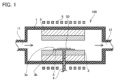
- FIG. 1 is a sectional view of the manufacturing apparatus 100.
- FIG. 2 is an enlarged cross-sectional view of the rotary shaft 4 in the manufacturing apparatus 100.
- FIG. 3 is a process drawing for forming an epitaxial layer on silicon carbide substrate 50.
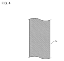
- FIG. 4 is an enlarged cross-sectional view of rotating shaft 4a in the silicon carbide epitaxial substrate manufacturing apparatus according to the first comparative example.
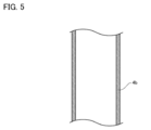
- FIG. 5 is an enlarged cross-sectional view of rotating shaft 4b in the silicon carbide epitaxial substrate manufacturing apparatus according to the second comparative example.
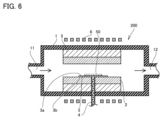
- FIG. 6 is a sectional view of the manufacturing apparatus 200.
- FIG. 7 is an enlarged cross-sectional view of the rotary shaft 4 in the manufacturing apparatus 200.
- FIG. 8 is a partial side view of the fitting portion between the first cylindrical portion 43 and the second cylindrical portion 44.
- An object of the present disclosure is to provide an apparatus for manufacturing a silicon carbide epitaxial substrate capable of suppressing nonuniformity of temperature on the rotating susceptor. [Effect of the present disclosure] According to the manufacturing apparatus for a silicon carbide epitaxial substrate according to the present disclosure, it is possible to suppress temperature nonuniformity on the rotating susceptor.
- a silicon carbide epitaxial substrate manufacturing apparatus includes a rotary susceptor on which the silicon carbide substrate is mounted, and a cylindrical rotary shaft attached to the rotary susceptor.
- a shield plate is formed on the inner peripheral surface of the rotary shaft so as to extend so as to intersect the central axis of the rotary shaft.
- the radiation through the cavity formed inside the rotating shaft is suppressed by the shield plate.
- heat radiation from the rotary susceptor via the rotary shaft is suppressed, and uneven temperature on the rotary susceptor can be suppressed.
- a silicon carbide epitaxial substrate manufacturing apparatus includes a rotary susceptor on which the silicon carbide substrate is placed, and a cylindrical rotary shaft attached to the rotary susceptor.
- the rotating shaft has a first cylindrical portion and a second cylindrical portion. The lower end of the first cylindrical portion is fitted into the upper end of the second cylindrical portion by point contact or line contact.
- the first cylindrical portion and the second cylindrical portion are fitted by point contact or line contact, and the heat transfer resistance increases at the fitting portion. There is. Therefore, according to the silicon carbide epitaxial substrate manufacturing apparatus of (2) above, heat radiation from the rotary susceptor via the rotary shaft is suppressed, and nonuniform temperature on the rotary susceptor can be suppressed.
- a shield plate extending so as to intersect the central axis of the rotary shaft may be formed on the inner peripheral surface of the rotary shaft.
- heat radiation from the rotary susceptor via the rotary shaft is further suppressed, and nonuniformity of temperature on the rotary susceptor can be further suppressed.
- the rotary shaft may be formed of silicon nitride, alumina, sapphire or zirconia.
- the above-mentioned material forming the rotating shaft is a material having a relatively low thermal conductivity, according to the silicon carbide epitaxial substrate manufacturing apparatus of (4) above, heat radiation to the outside of the chamber via the rotating shaft is further improved. As a result, the nonuniformity of the temperature on the rotating susceptor can be further suppressed.
- manufacturing apparatus 100 The configuration of the silicon carbide epitaxial substrate manufacturing apparatus (hereinafter, referred to as manufacturing apparatus 100) according to the first embodiment will be described below.
- the manufacturing apparatus 100 is a horizontal hot wall CVD apparatus.
- the manufacturing apparatus 100 includes a quartz tube 1, a heating element 2, a rotary susceptor 3, a rotary shaft 4, a heat insulating member 5, and an induction heating coil 6.
- the quartz tube 1 has a tubular shape. One end and the other end of the quartz tube 1 in the longitudinal direction are closed. A gas introduction pipe 11 is provided at one end of the quartz tube 1 in the longitudinal direction, and a gas discharge pipe 12 is provided at the other end of the quartz tube 1 in the longitudinal direction. The gas introduction pipe 11 and the gas discharge pipe 12 communicate with the inside of the quartz pipe 1.
- a carbon raw material gas, a silicon raw material gas, an impurity raw material gas and a carrier gas are introduced into the quartz pipe 1.
- propane (C 3 H 8 ) gas is used as the carbon source gas.
- silicon source gas for example, silane (SiH 4 ) gas is used.
- impurity raw material gas for example, ammonia (NH 3 ) gas and nitrogen (N 2 ) gas are used.
- Hydrogen (H 2 ) gas for example, is used as the carrier gas.
- the gas exhaust pipe 12 exhausts the gas remaining in the quartz pipe 1 after the epitaxial layer described later is formed on the silicon carbide substrate 50. In addition, in FIG. 1, the flows of these gases are indicated by arrows.
- the heating element 2 has a tubular shape.
- the heating element is made of graphite, for example.
- the heating element 2 is arranged inside the quartz tube 1. In the following, the space inside the heating element 2 may be referred to as a chamber.
- the rotary susceptor 3 has a first main surface 3a and a second main surface 3b. Silicon carbide substrate 50 (silicon carbide substrate 50 is shown by a dotted line in FIG. 1) is placed on first main surface 3a. The second main surface 3b is the surface opposite to the first main surface 3a.
- the rotary susceptor 3 is arranged inside the heating element 2.
- the rotary susceptor 3 is made of graphite, for example.
- the surface of the rotary susceptor 3 may be coated with silicon carbide.
- Rotating susceptor 3 may be made of silicon carbide.
- the rotary shaft 4 has a cylindrical shape.
- the rotary shaft 4 is attached to the rotary susceptor 3 (second main surface 3b) at one end.
- the rotating shaft 4 is attached to a drive mechanism (not shown) at the other end.
- the rotating shaft 4 extends in a direction intersecting the first main surface 3a and the second main surface 3b.
- the rotary shaft 4 is rotationally driven around its central axis by a drive mechanism. As a result, the rotary susceptor 3 rotates about its central axis.
- the rotating shaft 4 is made of a material having heat resistance and low thermal conductivity.
- the rotating shaft 4 is preferably made of a material whose thermal conductivity decreases as the temperature rises in a temperature range of at least 1000 ° C. or less.
- the thermal conductivity of the material forming the rotating shaft 4 is preferably 20 W / m ⁇ K or less when measured at 1000 ° C.
- the rotating shaft 4 is made of, for example, silicon nitride, alumina, sapphire, zirconia, or the like.
- FIG. 2 is an enlarged sectional view of the rotary shaft 4 in the manufacturing apparatus 100.
- a shield plate 41 and a shield plate 42 are formed on the inner peripheral surface of the rotary shaft 4.
- the shield plate 41 and the shield plate 42 extend from the inner peripheral surface of the rotating shaft 4 in a direction intersecting the central axis of the rotating shaft 4. At least a part of the shielding plate 41 is preferably separated from the inner peripheral surface of the rotating shaft 4. It is preferable that the shield plate 41 and the shield plate 42 have the same shape and are arranged at positions symmetrical with respect to the central axis of the rotation shaft 4. Further, it is preferable that the shield plate 41 and the shield plate 42 are formed so that no gap is formed when viewed from the rotary susceptor 3 side.
- the heat insulating member 5 is arranged between the heating element 2 and the quartz tube 1 so as to surround the outer peripheral surface of the heating element 2.
- the heat insulating member 5, the heating element 2 and the quartz tube 1 are formed with through holes for inserting the rotary shaft 4.
- the induction heating coil 6 is wound around the outer peripheral surface of the quartz tube 1. When the induction heating coil 6 is energized, it induction-heats the heating element 2 and the rotary susceptor 3. Silicon carbide substrate 50 is heated by heat conduction from rotary susceptor 3 and radiation from heating element 2 and rotary susceptor 3. Since the heat insulating member 5 is arranged between the heating element 2 and the quartz tube 1, the quartz tube 1 is hardly heated.
- FIG. 3 is a process drawing for forming an epitaxial layer on silicon carbide substrate 50.
- an epitaxial layer is formed on silicon carbide substrate 50 by performing preparatory step S1, placement step S2, temperature raising step S3, and epitaxial growth step S4.
- silicon carbide substrate 50 is prepared.
- Preparation of silicon carbide substrate 50 is performed, for example, by slicing an ingot made of a silicon carbide single crystal. This slicing is preferably performed so that the main surface of silicon carbide substrate 50 is inclined at a predetermined angle in a predetermined crystal orientation with respect to a predetermined crystal plane.
- the predetermined crystal plane is, for example, the ⁇ 0001 ⁇ plane
- the predetermined crystal orientation is the ⁇ 11-20> direction
- the predetermined angle is, for example, 2 ° or more and 6 ° or less.
- the silicon carbide substrate 50 prepared in the preparation step S1 is mounted on the rotary susceptor 3.
- the steps after the mounting step S2 are performed inside the manufacturing apparatus 100.
- the temperature raising step S3 by energizing the induction heating coil 6, the temperature inside the chamber is raised to a predetermined temperature.
- a raw material gas carbon raw material gas, silicon raw material gas, impurity raw material gas
- a carrier gas By reacting this source gas on the surface of silicon carbide substrate 50 placed on rotating susceptor 3, an epitaxial layer made of a single crystal of silicon carbide is formed on silicon carbide substrate 50.
- FIG. 4 is an enlarged cross-sectional view of rotating shaft 4a in the silicon carbide epitaxial substrate manufacturing apparatus according to the first comparative example.
- the silicon carbide epitaxial substrate manufacturing apparatus according to the first comparative example has the same configuration as manufacturing apparatus 100, except that rotary shaft 4a is used instead of rotary shaft 4.
- the rotating shaft 4a has a columnar shape. That is, since the rotating shaft 4a is formed of a solid member, the heat retained by the rotating susceptor 3 is easily released through the rotating shaft 4a by heat conduction, and the temperature on the rotating susceptor 3 is uniform. It is easy to lose the sex.
- FIG. 5 is an enlarged cross-sectional view of rotating shaft 4b in the silicon carbide epitaxial substrate manufacturing apparatus according to the second comparative example.
- the silicon carbide epitaxial substrate manufacturing apparatus according to the second comparative example has the same configuration as manufacturing apparatus 100, except that rotary shaft 4b is used instead of rotary shaft 4.
- the rotating shaft 4b has a cylindrical shape. That is, since the rotating shaft 4b is formed of a hollow member, the heat retained by the rotating susceptor 3 is less likely to be released through the rotating shaft 4a due to heat conduction. However, the rotating shaft 4b cannot prevent the heat held by the rotating susceptor 3 from being radiated through the internal space of the rotating shaft 4b.
- the shield plate 41 and the shield are provided on the inner peripheral surface of the rotating shaft 4. Since the plate 42 is formed, heat release from the rotary susceptor 3 due to radiation is suppressed. As described above, according to the manufacturing apparatus 100, the heat release from the rotary susceptor 3 via the rotary shaft 4 is suppressed as compared with the silicon carbide epitaxial substrate manufacturing apparatuses according to the first comparative example and the second comparative example. Therefore, it is possible to suppress the temperature nonuniformity on the rotary susceptor 3.
- the temperature nonuniformity on the rotating susceptor 3 causes the temperature nonuniformity on the silicon carbide substrate 50 placed thereon.
- the nonuniform temperature on silicon carbide substrate 50 causes the nonuniform carrier concentration in the epitaxial layer grown on silicon carbide substrate 50. Therefore, according to the manufacturing apparatus 100, it is possible to improve the uniformity of carrier concentration in the epitaxial layer.
- manufacturing apparatus 200 The configuration of a silicon carbide epitaxial substrate manufacturing apparatus (hereinafter, referred to as manufacturing apparatus 200) according to the second embodiment will be described below.
- manufacturing apparatus 200 The difference from the configuration of the manufacturing apparatus 100 will be mainly described, and repeated description will not be repeated.
- FIG. 6 is a sectional view of the manufacturing apparatus 200.
- the manufacturing apparatus 200 is a horizontal hot wall CVD apparatus.
- the manufacturing apparatus 200 includes a quartz tube 1, a heating element 2, a rotary susceptor 3, a rotary shaft 4, a heat insulating member 5, and an induction heating coil 6.
- a shield plate 41 and a shield plate 42 are formed on the inner peripheral surface of the rotating shaft 4.
- the configuration of the manufacturing apparatus 200 is common to the configuration of the manufacturing apparatus 100.
- the shield plate 41 and the shield plate 42 may not be formed on the inner peripheral surface of the rotating shaft 4.
- the rotary shaft 4 is divided into a plurality of parts in the direction along the central axis of the rotary shaft 4 (not shown in FIG. 6).
- FIG. 7 is an enlarged sectional view of the rotary shaft 4 in the manufacturing apparatus 200.
- FIG. 8 is a partial side view of the fitting portion between the first cylindrical portion 43 and the second cylindrical portion 44.
- the rotary shaft 4 is divided into a plurality of parts in a direction along the central axis of the rotary shaft 4. More specifically, the rotating shaft 4 has a first cylindrical portion 43 and a second cylindrical portion 44.
- the configuration of the manufacturing apparatus 200 is different from the configuration of the manufacturing apparatus 100.
- the first cylindrical portion 43 is located above the second cylindrical portion 44 (close to the rotary susceptor 3).
- the first cylindrical portion 43 and the second cylindrical portion 44 have a cylindrical shape.
- the first cylindrical portion 43 is attached to the rotary susceptor 3 (second main surface 3b) at its upper end portion.
- the second cylindrical portion 44 is attached to the lower end of the first cylindrical portion 43 at its upper end.
- the first cylindrical portion 43 is fitted into the upper end of the second cylindrical portion 44 at its lower end in point contact.
- the first cylindrical portion 43 may be fitted into the upper end portion of the second cylindrical portion 44 in line contact with the lower end portion thereof.
- the outer diameter of the lower end portion 43a of the first cylindrical portion 43 is smaller than the inner diameter of the upper end portion 44a of the second cylindrical portion 44.
- the lower end portion 43a of the first cylindrical portion 43 is inserted into the upper end portion 44a of the second cylindrical portion 44.
- the outer peripheral surface of the lower end portion 43a of the first cylindrical portion 43 and the inner peripheral surface of the upper end portion 44a of the second cylindrical portion 44 are in point contact or line contact with each other.
- the end surface on the lower end side of the first cylindrical portion 43 and the end surface on the upper end side of the second cylindrical portion 44 are in point contact or line contact with each other.
- a convex portion 43b is provided on the lower end side end surface of the first cylindrical portion 43, and a concave portion 44b is provided on the upper end side end surface of the second cylindrical portion 44.
- the operation of the manufacturing apparatus 200 is similar to that of the manufacturing apparatus 100. Therefore, the description of the operation of the manufacturing apparatus 200 is omitted here.
- the first cylindrical portion 43 and the second cylindrical portion 44 are fitted by point contact or line contact.
- the heat transfer resistance is large. Therefore, according to the manufacturing apparatus 200, heat radiation from the rotary susceptor 3 via the rotary shaft 4 is suppressed, and nonuniform temperature on the rotary susceptor 3 can be suppressed.
- the horizontal hot-wall CVD apparatus is given as an example of the manufacturing apparatus 100 and the manufacturing apparatus 200, but the manufacturing apparatus 100 and the manufacturing apparatus 200 may be a vertical hot-wall CVD apparatus.
Landscapes
- Chemical & Material Sciences (AREA)
- Engineering & Computer Science (AREA)
- Crystallography & Structural Chemistry (AREA)
- Materials Engineering (AREA)
- Metallurgy (AREA)
- Organic Chemistry (AREA)
- Inorganic Chemistry (AREA)
- Chemical Kinetics & Catalysis (AREA)
- General Chemical & Material Sciences (AREA)
- Chemical Vapour Deposition (AREA)
- Crystals, And After-Treatments Of Crystals (AREA)
Abstract
本開示の一態様に係る炭化珪素エピタキシャル基板の製造装置は、炭化珪素基板が載置される回転サセプタと、回転サセプタに取り付けられた円筒形状の回転軸とを備える。回転軸の内周面には、回転軸の中心軸と交差するように延在している遮蔽板が形成されている。
Description
本開示は、炭化珪素(SiC)エピタキシャル基板の製造装置に関する。本出願は、2018年11月20日に出願した日本特許出願である特願2018-217224号に基づく優先権を主張する。当該日本特許出願に記載された全ての記載内容は、参照によって本明細書に援用される。
例えば特許文献1(特開2018-108916号公報)には、ホットウォール式のCVD(Chemical Vapor Deposition)装置が記載されている。特許文献1に記載のCVD装置は、石英管と、発熱体と、回転サセプタと、誘導加熱コイルとを有している。
発熱体及び回転サセプタは、石英管の内部に配置されている。誘導加熱コイルは、石英管の外周面に沿って巻き回されている。誘導加熱コイルは、通電されることにより、発熱体を誘導加熱する。発熱体が発熱することにより、回転サセプタ上に載置された炭化珪素基板も加熱される。回転サセプタは、駆動機構に接続された回転軸が取り付けられている。
ホットウォール式CVD装置のチャンバ内には、原料ガス及びキャリアガスが供給される。これにより、炭化珪素基板上にエピタキシャル層が結晶成長する。この際、回転サセプタは、回転軸を回転駆動させることにより自転するように構成されている。
本開示の一態様に係る炭化珪素エピタキシャル基板の製造装置は、炭化珪素基板が載置される回転サセプタと、回転サセプタに取り付けられた円筒形状の回転軸とを備える。回転軸の内周面には、回転軸の中心軸と交差するように延在している遮蔽板が形成されている。
本開示の他の態様に係る炭化珪素エピタキシャル基板の製造装置は、炭化珪素基板が載置される回転サセプタと、回転サセプタに取り付けられた円筒形状の回転軸とを備える。回転軸は、第1円筒部と第2円筒部とを有している。第1円筒部の下端部は、第2円筒部の上端部に点接触又は線接触で嵌合されている。
[本開示が解決しようとする課題]
特許文献1に記載のCVD装置において、回転サセプタが保持している熱は、回転軸を介してチャンバの外部へと排出される。そのため、回転サセプタ上において温度の不均一が生じてしまう。
特許文献1に記載のCVD装置において、回転サセプタが保持している熱は、回転軸を介してチャンバの外部へと排出される。そのため、回転サセプタ上において温度の不均一が生じてしまう。
本開示の目的は、回転サセプタ上の温度の不均一を抑制することができる炭化珪素エピタキシャル基板の製造装置を提供することである。
[本開示の効果]
本開示に係る炭化珪素エピタキシャル基板の製造装置によると、回転サセプタ上の温度の不均一を抑制することができる。
[本開示の効果]
本開示に係る炭化珪素エピタキシャル基板の製造装置によると、回転サセプタ上の温度の不均一を抑制することができる。
[本開示に係る実施形態の説明]
まず、本開示に係る実施形態を列記して説明する。
まず、本開示に係る実施形態を列記して説明する。
(1)本開示の一態様に係る炭化珪素エピタキシャル基板の製造装置は、炭化珪素基板が載置される回転サセプタと、回転サセプタに取り付けられた円筒形状の回転軸とを備えている。回転軸の内周面には、回転軸の中心軸と交差するように延在している遮蔽板が形成されている。
上記(1)の炭化珪素エピタキシャル基板の製造装置においては、回転軸の内部に形成された空洞を介した輻射が、遮蔽板により抑制される。その結果、回転軸を介した回転サセプタからの放熱が抑制され、回転サセプタ上の温度の不均一を抑制することができる。
(2)本開示の他の態様に係る炭化珪素エピタキシャル基板の製造装置は、炭化珪素基板が載置される回転サセプタと、回転サセプタに取り付けられた円筒形状の回転軸とを備えている。回転軸は、第1円筒部と、第2円筒部とを有している。第1円筒部の下端部は、第2円筒部の上端部に点接触又は線接触で嵌合されている。
上記(2)の炭化珪素エピタキシャル基板の製造装置においては、第1円筒部と第2円筒部とが点接触又は線接触で嵌合されており、当該嵌合部において伝熱抵抗が大きくなっている。そのため、上記(2)の炭化珪素エピタキシャル基板の製造装置によると、回転軸を介した回転サセプタからの放熱が抑制され、回転サセプタ上の温度の不均一を抑制することができる。
(3)上記(2)の炭化珪素エピタキシャル基板の製造装置において、回転軸の内周面には、回転軸の中心軸と交差するように延在している遮蔽板が形成されていてもよい。
上記(3)の炭化珪素エピタキシャル基板の製造装置によると、回転軸を介した回転サセプタからの放熱がさらに抑制され、回転サセプタ上の温度の不均一をさらに抑制することができる。
(4)上記(1)~上記(3)の炭化珪素エピタキシャル基板の製造装置において、回転軸は、窒化珪素、アルミナ、サファイア又はジルコニアで形成されていてもよい。
回転軸を構成する上記の材料は熱伝導率が相対的に低い材料であるため、上記(4)の炭化珪素エピタキシャル基板の製造装置によると、回転軸を介したチャンバの外部への放熱がさらに抑制され、回転サセプタ上の温度の不均一をさらに抑制することができる。
[本開示に係る実施形態の詳細]
本開示に係る実施形態の詳細を、図面を参酌しながら説明する。なお、以下の図面においては、同一又は相当する部分に同一の参照記号を付すものとし、重複する説明は繰り返さないものとする。
本開示に係る実施形態の詳細を、図面を参酌しながら説明する。なお、以下の図面においては、同一又は相当する部分に同一の参照記号を付すものとし、重複する説明は繰り返さないものとする。
(第1実施形態)
以下に、第1実施形態に係る炭化珪素エピタキシャル基板の製造装置(以下においては、製造装置100という)の構成を説明する。
以下に、第1実施形態に係る炭化珪素エピタキシャル基板の製造装置(以下においては、製造装置100という)の構成を説明する。
図1は、製造装置100の断面図である。図1に示されるように、製造装置100は、横型のホットウォール式CVD装置である。製造装置100は、石英管1と、発熱体2と、回転サセプタ3と、回転軸4と、断熱部材5と、誘導加熱コイル6とを有している。
石英管1は、筒状の形状を有している。石英管1の長手方向における一方端及び他方端は、閉塞されている。石英管1の長手方向における一方端には、ガス導入管11が設けられており、石英管1の長手方向における他方端には、ガス排出管12が設けられている。ガス導入管11及びガス排出管12は、石英管1の内部に連通している。
ガス導入管11からは、石英管1の内部に炭素原料ガス、珪素原料ガス、不純物原料ガス及びキャリアガスが導入される。炭素原料ガスには、例えば、プロパン(C3H8)ガスが用いられる。珪素原料ガスには、例えばシラン(SiH4)ガスが用いられる。不純物原料ガスには、例えばアンモニア(NH3)ガス及び窒素(N2)ガスが用いられる。キャリアガスには、例えば水素(H2)ガスが用いられる。ガス排出管12からは、後述するエピタキシャル層が炭化珪素基板50上に形成された後に石英管1内に残存するガスが排出される。なお、図1中において、これらのガスの流れは、矢印で示されている。
発熱体2は、筒状の形状を有している。発熱体は、例えば黒鉛で形成されている。発熱体2は、石英管1の内部に配置されている。なお、以下においては、発熱体2の内部の空間を、チャンバということがある。
回転サセプタ3は、第1主面3aと第2主面3bとを有している。第1主面3a上には、炭化珪素基板50(炭化珪素基板50は、図1中において点線で示されている)が載置されている。第2主面3bは、第1主面3aの反対面である。回転サセプタ3は発熱体2の内部に配置されている。回転サセプタ3は、例えば黒鉛で形成されている。回転サセプタ3の表面は炭化珪素によりコーティングされていてもよい。回転サセプタ3は、炭化珪素で形成されていてもよい。
回転軸4は、円筒形状を有している。回転軸4は、一方端において、回転サセプタ3(第2主面3b)に取り付けられている。回転軸4は、他方端において、駆動機構(図示せず)に取り付けられている。回転軸4は、第1主面3a及び第2主面3bに交差する方向に延在している。回転軸4は、駆動機構により、その中心軸周りに回転駆動される。その結果、回転サセプタ3は、その中心軸周りに回転することになる。
回転軸4は、耐熱性があり、かつ、熱伝導率が低い材料で形成されている。回転軸4は、少なくとも1000℃以下の温度範囲において、温度上昇に伴って熱伝導率が低下する材料で構成されていることが好ましい。回転軸4を構成する材料の熱伝導率は、1000℃で測定した際に、20W/m・K以下であることが好ましい。回転軸4は、例えば、窒化珪素、アルミナ、サファイア、ジルコニア等で形成されている。
図2は、製造装置100における回転軸4の拡大断面図である。図2に示されるように、回転軸4の内周面には遮蔽板41及び遮蔽板42が形成されている。遮蔽板41及び遮蔽板42は、回転軸4の内周面から、回転軸4の中心軸に交差する方向に延在している。遮蔽板41は、少なくとも一部において、回転軸4の内周面から離間していることが好ましい。遮蔽板41及び遮蔽板42は、互いに同一の形状を有しており、回転軸4の中心軸に関して対称な位置に配置されていることが好ましい。また、遮蔽板41及び遮蔽板42は、回転サセプタ3側から見て隙間が生じないように形成されていることが好ましい。
図1に示されるように、断熱部材5は、発熱体2の外周面を取り囲むように、発熱体2と石英管1との間に配置されている。なお、断熱部材5、発熱体2及び石英管1には、回転軸4を挿通するための貫通穴が形成されている。
誘導加熱コイル6は、石英管1の外周面に沿って巻き回されている。誘導加熱コイル6は、通電されることにより、発熱体2及び回転サセプタ3を誘導加熱する。炭化珪素基板50は、回転サセプタ3からの熱伝導並びに発熱体2及び回転サセプタ3からの輻射により、加熱される。なお、発熱体2と石英管1との間には断熱部材5が配置されているため、石英管1は殆ど加熱されない。
以下に、製造装置100の動作を説明する。図3は、炭化珪素基板50上にエピタキシャル層を形成する際の工程図である。図3に示されるように、準備工程S1、載置工程S2、昇温工程S3及びエピタキシャル成長工程S4が行われることにより、炭化珪素基板50上にエピタキシャル層が形成される。
準備工程S1においては、炭化珪素基板50が準備される。炭化珪素基板50の準備は、例えば、炭化珪素単結晶からなるインゴットをスライスすることにより行われる。このスライスは、炭化珪素基板50の主面が所定の結晶面に対して所定の結晶方位において所定の角度だけ傾くように行われることが好ましい。この所定の結晶面は例えば{0001}面であり、この所定の結晶方位は<11-20>方向であり、所定の角度は例えば2°以上6°以下である。このスライスが行われた後に、炭化珪素基板50の表面は、研磨されてもよい。
載置工程S2においては、準備工程S1において準備された炭化珪素基板50が、回転サセプタ3上に載置される。載置工程S2以降の工程は、製造装置100の内部において行われる。
昇温工程S3においては、誘導加熱コイル6に通電することにより、チャンバ内が所定の温度まで昇温される。
エピタキシャル成長工程S4においては、ガス導入管11を介して、チャンバ内に原料ガス(炭素原料ガス、珪素原料ガス、不純物原料ガス)及びキャリアガスが導入される。この原料ガスが回転サセプタ3上に載置された炭化珪素基板50の表面において反応することにより、炭化珪素の単結晶からなるエピタキシャル層が、炭化珪素基板50上に形成される。
以下に、製造装置100の効果を比較例と対比しながら説明する。
図4は、第1比較例に係る炭化珪素エピタキシャル基板の製造装置における回転軸4aの拡大断面図である。第1比較例に係る炭化珪素エピタキシャル基板の製造装置は、回転軸4に代えて回転軸4aが用いられている点を除き、製造装置100と同一の構成を有している。
図4は、第1比較例に係る炭化珪素エピタキシャル基板の製造装置における回転軸4aの拡大断面図である。第1比較例に係る炭化珪素エピタキシャル基板の製造装置は、回転軸4に代えて回転軸4aが用いられている点を除き、製造装置100と同一の構成を有している。
図4に示されるように、回転軸4aは、円柱形状を有している。すなわち、回転軸4aは、中実の部材で形成されているため、回転サセプタ3が保持している熱は、熱伝導により回転軸4aを介して放出されやすく、回転サセプタ3上における温度の均一性が損なわれやすい。
図5は、第2比較例に係る炭化珪素エピタキシャル基板の製造装置における回転軸4bの拡大断面図である。第2比較例に係る炭化珪素エピタキシャル基板の製造装置は、回転軸4に代えて回転軸4bが用いられている点を除き、製造装置100と同一の構成を有している。
図5に示されるように、回転軸4bは、円筒形状を有している。すなわち、回転軸4bは、中空の部材で形成されているため、回転サセプタ3が保持している熱は、熱伝導により回転軸4aを介して放出されにくい。しかしながら、回転軸4bは回転サセプタ3の保持している熱が回転軸4bの内部空間を介して輻射により放出されてしまうことを抑制できない。
一方で、製造装置100においては、回転軸4が円筒形状を有している(回転軸4が中空部材で形成されている)ことに加え、回転軸4の内周面に遮蔽板41及び遮蔽板42が形成されているため、輻射による回転サセプタ3からの熱の放出が抑制されている。このように、製造装置100によると、第1比較例及び第2比較例に係る炭化珪素エピタキシャル基板の製造装置と比較して、回転軸4を介した回転サセプタ3からの熱の放出を抑制することができ、回転サセプタ3上における温度の不均一が抑制できる。
なお、回転サセプタ3上における温度の不均一は、その上に載置されている炭化珪素基板50上における温度の不均一の原因となる。炭化珪素基板50上における温度の不均一は、炭化珪素基板50上に成長するエピタキシャル層中におけるキャリア濃度の不均一の原因となる。そのため、製造装置100によると、エピタキシャル層中におけるキャリア濃度の均一性を高めることが可能となる。
(第2実施形態)
以下に、第2実施形態に係る炭化珪素エピタキシャル基板の製造装置(以下においては、製造装置200という)の構成を説明する。ここでは、製造装置100の構成と異なる点を主に説明し、重複する説明は繰り返さない。
以下に、第2実施形態に係る炭化珪素エピタキシャル基板の製造装置(以下においては、製造装置200という)の構成を説明する。ここでは、製造装置100の構成と異なる点を主に説明し、重複する説明は繰り返さない。
図6は、製造装置200の断面図である。図6に示されるように、製造装置200は、横型のホットウォール式CVD装置である。製造装置200は、石英管1と、発熱体2と、回転サセプタ3と、回転軸4と、断熱部材5と、誘導加熱コイル6とを有している。回転軸4の内周面には、遮蔽板41及び遮蔽板42が形成されている。これらの点に関して、製造装置200の構成は、製造装置100の構成と共通している。但し、製造装置200においては、回転軸4の内周面に遮蔽板41及び遮蔽板42が形成されていなくてもよい。また、後述するように、製造装置200において、回転軸4は、回転軸4の中心軸に沿う方向において、複数の部分に分割されている(図6中において図示せず)。
図7は、製造装置200における回転軸4の拡大断面図である。図8は、第1円筒部43と第2円筒部44との嵌合部における部分側面図である。図7及び8に示されるように、回転軸4は、回転軸4の中心軸に沿う方向において、複数の部分に分割されている。より具体的には、回転軸4は、第1円筒部43と、第2円筒部44とを有している。この点に関して、製造装置200の構成は、製造装置100の構成と異なっている。
第1円筒部43は、第2円筒部44の上方に位置している(回転サセプタ3に近い位置にある)。第1円筒部43及び第2円筒部44は、円筒形状を有している。第1円筒部43は、その上端部において、回転サセプタ3(第2主面3b)に取り付けられている。第2円筒部44は、その上端部において、第1円筒部43の下端部に取り付けられている。
第1円筒部43は、その下端部において、第2円筒部44の上端部と点接触で嵌合されている。第1円筒部43は、その下端部において、第2円筒部44の上端部と線接触で嵌合されていてもよい。
より具体的には、図7に示されるように、第1円筒部43の下端部43aにおける外径は、第2円筒部44の上端部44aにおける内径よりも小さくなっている。第1円筒部43の下端部43aが、第2円筒部44の上端部44aに挿入されている。この際、第1円筒部43の下端部43aにおける外周面と第2円筒部44の上端部44aにおける内周面とは互いに点接触又は線接触している。第1円筒部43の下端側の端面と第2円筒部44の上端側における端面とは、互いに点接触又は線接触している。図8に示されるように、第1円筒部43の下端側の端面には凸部43bが設けられており、第2円筒部44の上端側の端面には凹部44bが設けられている。凸部43bが凹部44bに点接触又は線接触するように挿入されることにより、第1円筒部43の第2円筒部44に対する回転軸4の中心軸周りの相対的な回転が抑止されている。
製造装置200の動作は、製造装置100の動作と同様である。そのため、ここでは、製造装置200の動作に関する説明は省略する。
以下に、製造装置200の効果を説明する。ここでは、製造装置100の効果と異なる点を主に説明し、重複する説明は繰り返さない。
製造装置200においては、第1円筒部43と第2円筒部44とが点接触又は線接触で嵌合されている。当該嵌合部においては、第1円筒部43と第2円筒部44との接触部位が限定されているため、伝熱抵抗が大きくなっている。そのため、製造装置200によると、回転軸4を介した回転サセプタ3からの放熱が抑制され、回転サセプタ3上の温度の不均一を抑制することができる。
(変形例)
上記においては、製造装置100及び製造装置200の例として、横型のホットウォール式CVD装置を挙げたが、製造装置100及び製造装置200は、縦型のホットウォール式CVD装置であってもよい。
上記においては、製造装置100及び製造装置200の例として、横型のホットウォール式CVD装置を挙げたが、製造装置100及び製造装置200は、縦型のホットウォール式CVD装置であってもよい。
今回開示された実施の形態は全ての点で例示であって、制限的なものではないと考えられるべきである。本発明の範囲は、上記した実施形態ではなく、請求の範囲によって示され、請求の範囲と均等の意味及び範囲内での全ての変更が含まれることが意図される。
1 石英管、11 ガス導入管、12 ガス排出管、2 発熱体、3 回転サセプタ、3a 第1主面、3b 第2主面、4,4a,4b 回転軸、41,42 遮蔽板、43 第1円筒部、43a 下端部、43b 凸部、44 第2円筒部、44a 上端部、44b 凹部、5 断熱部材、6 誘導加熱コイル、100,200 製造装置、S1 準備工程、S2 載置工程、S3 昇温工程、S4 エピタキシャル成長工程、50 炭化珪素基板
Claims (4)
- 炭化珪素基板が載置される回転サセプタと、
前記回転サセプタに取り付けられた円筒形状の回転軸とを備え、
前記回転軸の内周面には、前記回転軸の中心軸と交差するように延在している遮蔽板が形成されている、炭化珪素エピタキシャル基板の製造装置。 - 炭化珪素基板が載置される回転サセプタと、
前記回転サセプタに取り付けられた円筒形状の回転軸とを備え、
前記回転軸は、第1円筒部と、第2円筒部とを有しており、
前記第1円筒部の下端部は、前記第2円筒部の上端部に点接触又は線接触で嵌合されている、炭化珪素エピタキシャル基板の製造装置。 - 前記回転軸の内周面には、前記回転軸の中心軸と交差するように延在している遮蔽板が形成されている、請求項2に記載の炭化珪素エピタキシャル基板の製造装置。
- 前記回転軸は、窒化珪素、アルミナ、サファイア又はジルコニアで形成されている、請求項1~請求項3のいずれか1項に記載の炭化珪素エピタキシャル基板の製造装置。
Priority Applications (1)
| Application Number | Priority Date | Filing Date | Title |
|---|---|---|---|
| JP2020558075A JPWO2020105211A1 (ja) | 2018-11-20 | 2019-07-02 | 炭化珪素エピタキシャル基板の製造装置 |
Applications Claiming Priority (2)
| Application Number | Priority Date | Filing Date | Title |
|---|---|---|---|
| JP2018217224 | 2018-11-20 | ||
| JP2018-217224 | 2018-11-20 |
Publications (1)
| Publication Number | Publication Date |
|---|---|
| WO2020105211A1 true WO2020105211A1 (ja) | 2020-05-28 |
Family
ID=70773989
Family Applications (1)
| Application Number | Title | Priority Date | Filing Date |
|---|---|---|---|
| PCT/JP2019/026260 Ceased WO2020105211A1 (ja) | 2018-11-20 | 2019-07-02 | 炭化珪素エピタキシャル基板の製造装置 |
Country Status (2)
| Country | Link |
|---|---|
| JP (1) | JPWO2020105211A1 (ja) |
| WO (1) | WO2020105211A1 (ja) |
Cited By (1)
| Publication number | Priority date | Publication date | Assignee | Title |
|---|---|---|---|---|
| WO2024257580A1 (ja) * | 2023-06-16 | 2024-12-19 | 住友電気工業株式会社 | 炭化珪素エピタキシャル基板、炭化珪素半導体装置の製造方法および炭化珪素エピタキシャル基板の製造方法 |
Citations (5)
| Publication number | Priority date | Publication date | Assignee | Title |
|---|---|---|---|---|
| JPH06204134A (ja) * | 1992-12-29 | 1994-07-22 | Nippei Toyama Corp | バイアス電極付昇降回転テーブル装置 |
| JPH0997765A (ja) * | 1995-09-29 | 1997-04-08 | Toshiba Corp | 基板処理装置 |
| JPH10165875A (ja) * | 1996-12-06 | 1998-06-23 | Dainippon Screen Mfg Co Ltd | 基板回転保持装置および回転式基板処理装置 |
| JP2005285939A (ja) * | 2004-03-29 | 2005-10-13 | Sharp Corp | 気相成長装置および気相成長方法 |
| JP2008171933A (ja) * | 2007-01-10 | 2008-07-24 | Sumitomo Electric Ind Ltd | 半導体製造装置 |
-
2019
- 2019-07-02 WO PCT/JP2019/026260 patent/WO2020105211A1/ja not_active Ceased
- 2019-07-02 JP JP2020558075A patent/JPWO2020105211A1/ja active Pending
Patent Citations (5)
| Publication number | Priority date | Publication date | Assignee | Title |
|---|---|---|---|---|
| JPH06204134A (ja) * | 1992-12-29 | 1994-07-22 | Nippei Toyama Corp | バイアス電極付昇降回転テーブル装置 |
| JPH0997765A (ja) * | 1995-09-29 | 1997-04-08 | Toshiba Corp | 基板処理装置 |
| JPH10165875A (ja) * | 1996-12-06 | 1998-06-23 | Dainippon Screen Mfg Co Ltd | 基板回転保持装置および回転式基板処理装置 |
| JP2005285939A (ja) * | 2004-03-29 | 2005-10-13 | Sharp Corp | 気相成長装置および気相成長方法 |
| JP2008171933A (ja) * | 2007-01-10 | 2008-07-24 | Sumitomo Electric Ind Ltd | 半導体製造装置 |
Cited By (1)
| Publication number | Priority date | Publication date | Assignee | Title |
|---|---|---|---|---|
| WO2024257580A1 (ja) * | 2023-06-16 | 2024-12-19 | 住友電気工業株式会社 | 炭化珪素エピタキシャル基板、炭化珪素半導体装置の製造方法および炭化珪素エピタキシャル基板の製造方法 |
Also Published As
| Publication number | Publication date |
|---|---|
| JPWO2020105211A1 (ja) | 2021-09-30 |
Similar Documents
| Publication | Publication Date | Title |
|---|---|---|
| JP5001349B2 (ja) | サセプタ及びこれを備える半導体製造装置 | |
| JP5394188B2 (ja) | 化学気相蒸着装置 | |
| JP4262763B2 (ja) | 半導体製造装置および半導体製造方法 | |
| US9194056B2 (en) | Film-forming apparatus and method | |
| KR20080081823A (ko) | 복사 가열을 이용한 마이크로배치 증착 챔버 | |
| KR20130111029A (ko) | 화학 기상 증착 장치용 서셉터 및 이를 구비하는 화학 기상 증착 장치 | |
| KR101420126B1 (ko) | 성막 장치 및 성막 방법 | |
| CN111261548B (zh) | SiC化学气相沉积装置和SiC外延晶片的制造方法 | |
| JP2009135228A (ja) | 気相成長装置および気相成長方法 | |
| CN111033692B (zh) | 气相生长方法 | |
| US12309888B2 (en) | Heated substrate support | |
| WO2020105211A1 (ja) | 炭化珪素エピタキシャル基板の製造装置 | |
| JP6562546B2 (ja) | ウェハ支持台、ウェハ支持体、化学気相成長装置 | |
| US20210217648A1 (en) | Susceptor and chemical vapor deposition apparatus | |
| JP7143638B2 (ja) | 炭化珪素エピタキシャル基板の製造方法 | |
| JP5208850B2 (ja) | 成膜装置 | |
| WO2020105212A1 (ja) | 炭化珪素エピタキシャル基板の製造装置 | |
| JP4916736B2 (ja) | 半導体結晶の成長装置 | |
| JP7419704B2 (ja) | 化学的気相成長装置 | |
| JP2007042846A (ja) | ハイドライド気相成長装置、iii族窒化物半導体基板の製造方法及びiii族窒化物半導体基板 | |
| JP2013016562A (ja) | 気相成長方法 | |
| JPH097956A (ja) | 半導体熱処理用電気抵抗発熱体 | |
| CN115637490A (zh) | 集成式分子束外延坩埚制作方法、外延坩埚及分子束源炉 | |
| JP2013135190A (ja) | 半導体製造装置及び成膜方法 | |
| JP2007234775A (ja) | 半導体製造装置 |
Legal Events
| Date | Code | Title | Description |
|---|---|---|---|
| 121 | Ep: the epo has been informed by wipo that ep was designated in this application |
Ref document number: 19886468 Country of ref document: EP Kind code of ref document: A1 |
|
| ENP | Entry into the national phase |
Ref document number: 2020558075 Country of ref document: JP Kind code of ref document: A |
|
| NENP | Non-entry into the national phase |
Ref country code: DE |
|
| 122 | Ep: pct application non-entry in european phase |
Ref document number: 19886468 Country of ref document: EP Kind code of ref document: A1 |