WO2020105159A1 - 磁性体粒子の操作方法及び装置 - Google Patents
磁性体粒子の操作方法及び装置Info
- Publication number
- WO2020105159A1 WO2020105159A1 PCT/JP2018/043106 JP2018043106W WO2020105159A1 WO 2020105159 A1 WO2020105159 A1 WO 2020105159A1 JP 2018043106 W JP2018043106 W JP 2018043106W WO 2020105159 A1 WO2020105159 A1 WO 2020105159A1
- Authority
- WO
- WIPO (PCT)
- Prior art keywords
- magnetic
- gel
- layer
- treatment liquid
- magnetic particles
- Prior art date
- Legal status (The legal status is an assumption and is not a legal conclusion. Google has not performed a legal analysis and makes no representation as to the accuracy of the status listed.)
- Ceased
Links
Images



Classifications
-
- C—CHEMISTRY; METALLURGY
- C12—BIOCHEMISTRY; BEER; SPIRITS; WINE; VINEGAR; MICROBIOLOGY; ENZYMOLOGY; MUTATION OR GENETIC ENGINEERING
- C12N—MICROORGANISMS OR ENZYMES; COMPOSITIONS THEREOF; PROPAGATING, PRESERVING, OR MAINTAINING MICROORGANISMS; MUTATION OR GENETIC ENGINEERING; CULTURE MEDIA
- C12N15/00—Mutation or genetic engineering; DNA or RNA concerning genetic engineering, vectors, e.g. plasmids, or their isolation, preparation or purification; Use of hosts therefor
- C12N15/09—Recombinant DNA-technology
- C12N15/10—Processes for the isolation, preparation or purification of DNA or RNA
- C12N15/1003—Extracting or separating nucleic acids from biological samples, e.g. pure separation or isolation methods; Conditions, buffers or apparatuses therefor
- C12N15/1006—Extracting or separating nucleic acids from biological samples, e.g. pure separation or isolation methods; Conditions, buffers or apparatuses therefor by means of a solid support carrier, e.g. particles, polymers
- C12N15/1013—Extracting or separating nucleic acids from biological samples, e.g. pure separation or isolation methods; Conditions, buffers or apparatuses therefor by means of a solid support carrier, e.g. particles, polymers by using magnetic beads
-
- B—PERFORMING OPERATIONS; TRANSPORTING
- B01—PHYSICAL OR CHEMICAL PROCESSES OR APPARATUS IN GENERAL
- B01J—CHEMICAL OR PHYSICAL PROCESSES, e.g. CATALYSIS OR COLLOID CHEMISTRY; THEIR RELEVANT APPARATUS
- B01J19/00—Chemical, physical or physico-chemical processes in general; Their relevant apparatus
- B01J19/08—Processes employing the direct application of electric or wave energy, or particle radiation; Apparatus therefor
- B01J19/087—Processes employing the direct application of electric or wave energy, or particle radiation; Apparatus therefor employing electric or magnetic energy
-
- B—PERFORMING OPERATIONS; TRANSPORTING
- B03—SEPARATION OF SOLID MATERIALS USING LIQUIDS OR USING PNEUMATIC TABLES OR JIGS; MAGNETIC OR ELECTROSTATIC SEPARATION OF SOLID MATERIALS FROM SOLID MATERIALS OR FLUIDS; SEPARATION BY HIGH-VOLTAGE ELECTRIC FIELDS
- B03C—MAGNETIC OR ELECTROSTATIC SEPARATION OF SOLID MATERIALS FROM SOLID MATERIALS OR FLUIDS; SEPARATION BY HIGH-VOLTAGE ELECTRIC FIELDS
- B03C1/00—Magnetic separation
- B03C1/005—Pretreatment specially adapted for magnetic separation
-
- B—PERFORMING OPERATIONS; TRANSPORTING
- B03—SEPARATION OF SOLID MATERIALS USING LIQUIDS OR USING PNEUMATIC TABLES OR JIGS; MAGNETIC OR ELECTROSTATIC SEPARATION OF SOLID MATERIALS FROM SOLID MATERIALS OR FLUIDS; SEPARATION BY HIGH-VOLTAGE ELECTRIC FIELDS
- B03C—MAGNETIC OR ELECTROSTATIC SEPARATION OF SOLID MATERIALS FROM SOLID MATERIALS OR FLUIDS; SEPARATION BY HIGH-VOLTAGE ELECTRIC FIELDS
- B03C1/00—Magnetic separation
- B03C1/005—Pretreatment specially adapted for magnetic separation
- B03C1/01—Pretreatment specially adapted for magnetic separation by addition of magnetic adjuvants
-
- B—PERFORMING OPERATIONS; TRANSPORTING
- B03—SEPARATION OF SOLID MATERIALS USING LIQUIDS OR USING PNEUMATIC TABLES OR JIGS; MAGNETIC OR ELECTROSTATIC SEPARATION OF SOLID MATERIALS FROM SOLID MATERIALS OR FLUIDS; SEPARATION BY HIGH-VOLTAGE ELECTRIC FIELDS
- B03C—MAGNETIC OR ELECTROSTATIC SEPARATION OF SOLID MATERIALS FROM SOLID MATERIALS OR FLUIDS; SEPARATION BY HIGH-VOLTAGE ELECTRIC FIELDS
- B03C1/00—Magnetic separation
- B03C1/02—Magnetic separation acting directly on the substance being separated
- B03C1/025—High gradient magnetic separators
- B03C1/031—Component parts; Auxiliary operations
- B03C1/033—Component parts; Auxiliary operations characterised by the magnetic circuit
- B03C1/0332—Component parts; Auxiliary operations characterised by the magnetic circuit using permanent magnets
-
- B—PERFORMING OPERATIONS; TRANSPORTING
- B03—SEPARATION OF SOLID MATERIALS USING LIQUIDS OR USING PNEUMATIC TABLES OR JIGS; MAGNETIC OR ELECTROSTATIC SEPARATION OF SOLID MATERIALS FROM SOLID MATERIALS OR FLUIDS; SEPARATION BY HIGH-VOLTAGE ELECTRIC FIELDS
- B03C—MAGNETIC OR ELECTROSTATIC SEPARATION OF SOLID MATERIALS FROM SOLID MATERIALS OR FLUIDS; SEPARATION BY HIGH-VOLTAGE ELECTRIC FIELDS
- B03C1/00—Magnetic separation
- B03C1/02—Magnetic separation acting directly on the substance being separated
- B03C1/28—Magnetic plugs and dipsticks
- B03C1/284—Magnetic plugs and dipsticks with associated cleaning means, e.g. retractable non-magnetic sleeve
-
- B—PERFORMING OPERATIONS; TRANSPORTING
- B03—SEPARATION OF SOLID MATERIALS USING LIQUIDS OR USING PNEUMATIC TABLES OR JIGS; MAGNETIC OR ELECTROSTATIC SEPARATION OF SOLID MATERIALS FROM SOLID MATERIALS OR FLUIDS; SEPARATION BY HIGH-VOLTAGE ELECTRIC FIELDS
- B03C—MAGNETIC OR ELECTROSTATIC SEPARATION OF SOLID MATERIALS FROM SOLID MATERIALS OR FLUIDS; SEPARATION BY HIGH-VOLTAGE ELECTRIC FIELDS
- B03C1/00—Magnetic separation
- B03C1/02—Magnetic separation acting directly on the substance being separated
- B03C1/28—Magnetic plugs and dipsticks
- B03C1/288—Magnetic plugs and dipsticks disposed at the outer circumference of a recipient
-
- B—PERFORMING OPERATIONS; TRANSPORTING
- B03—SEPARATION OF SOLID MATERIALS USING LIQUIDS OR USING PNEUMATIC TABLES OR JIGS; MAGNETIC OR ELECTROSTATIC SEPARATION OF SOLID MATERIALS FROM SOLID MATERIALS OR FLUIDS; SEPARATION BY HIGH-VOLTAGE ELECTRIC FIELDS
- B03C—MAGNETIC OR ELECTROSTATIC SEPARATION OF SOLID MATERIALS FROM SOLID MATERIALS OR FLUIDS; SEPARATION BY HIGH-VOLTAGE ELECTRIC FIELDS
- B03C2201/00—Details of magnetic or electrostatic separation
- B03C2201/18—Magnetic separation whereby the particles are suspended in a liquid
-
- B—PERFORMING OPERATIONS; TRANSPORTING
- B03—SEPARATION OF SOLID MATERIALS USING LIQUIDS OR USING PNEUMATIC TABLES OR JIGS; MAGNETIC OR ELECTROSTATIC SEPARATION OF SOLID MATERIALS FROM SOLID MATERIALS OR FLUIDS; SEPARATION BY HIGH-VOLTAGE ELECTRIC FIELDS
- B03C—MAGNETIC OR ELECTROSTATIC SEPARATION OF SOLID MATERIALS FROM SOLID MATERIALS OR FLUIDS; SEPARATION BY HIGH-VOLTAGE ELECTRIC FIELDS
- B03C2201/00—Details of magnetic or electrostatic separation
- B03C2201/26—Details of magnetic or electrostatic separation for use in medical or biological applications
-
- C—CHEMISTRY; METALLURGY
- C12—BIOCHEMISTRY; BEER; SPIRITS; WINE; VINEGAR; MICROBIOLOGY; ENZYMOLOGY; MUTATION OR GENETIC ENGINEERING
- C12M—APPARATUS FOR ENZYMOLOGY OR MICROBIOLOGY; APPARATUS FOR CULTURING MICROORGANISMS FOR PRODUCING BIOMASS, FOR GROWING CELLS OR FOR OBTAINING FERMENTATION OR METABOLIC PRODUCTS, i.e. BIOREACTORS OR FERMENTERS
- C12M1/00—Apparatus for enzymology or microbiology
Definitions
- the present invention relates to a magnetic particle operating method and apparatus for performing a process such as extraction of nucleic acid using magnetic particles.
- a device for manipulating magnetic particles (hereinafter, also simply referred to as a device) for performing the above-mentioned treatment has a treatment liquid layer composed of a washing liquid or the like and a gel layer alternately arranged in the longitudinal direction of the container in a tubular container. (See Patent Documents 1 and 2).
- a sample layer containing magnetic particles adsorbing a target component is arranged at one end of the device.
- a magnetic source is arranged outside the sample layer of the device to collect magnetic particles in the sample by a magnetic field.
- the magnetic particles having the target component adsorbed move in the device following the operation of the magnetic force source.
- the magnetic particles with the target component adsorbed can be passed through the gel layer by slowly moving the magnetic force source to the other end of the device.
- the treatment liquid layer is composed of a cleaning liquid
- the magnetic force source when the magnetic force source is quickly reciprocated in the longitudinal direction of the device in the treatment liquid layer, the magnetic particles cannot follow the operation of the magnetic force source and are dispersed in the cleaning liquid. To do. By this operation, the contaminant components adhering to the target component are washed off in the treatment liquid layer.
- the magnetic particles are moved to the eluent layer located at the other end of the device, and the target component is released from the magnetic particles in the eluent layer.
- part of the gel in the gel layer often enters the treatment liquid layer together with the magnetic particles and adheres to the inner wall surface of the treatment liquid layer.
- the magnetic particles dispersed in the treatment liquid layer come into contact with the gel attached to the inner wall surface, the magnetic particles are captured by the gel, resulting in a problem that the recovery rate of the target component is lowered.
- the present invention is intended to suppress the decrease in the recovery rate of the target component due to the gel attached to the inner wall surface of the treatment liquid layer.
- the method according to the present invention includes a first method and a second method.
- the magnetic particles in the magnetic particle manipulation device in which the treatment liquid layer and the gel layer are layered in the tubular container in the longitudinal direction of the tubular container are magnetically supplied from the outside of the magnetic particle manipulation device. It is a method of operating by.
- a first method according to the present invention is that, after passing the gel layer through the magnetic particles, the magnetic source is moved to move the magnetic particles in the treatment liquid layer adjacent to the gel layer.
- the operating speed of the magnetic source within a range of a certain distance from the gel layer through which the magnetic particles have passed is greater than the certain distance from the gel layer.
- the operation speed is set to be slower than the operating speed of the magnetic force source within a remote range.
- the operating speed of the magnetic force source within the range of the constant distance is set to a speed at which the magnetic particles are not captured by the gel existing within the range of the constant distance. By doing so, the magnetic particles trapped by the gel that has entered the treatment liquid layer can be further reduced.
- a second method according to the present invention is characterized in that, after passing the gel layer through the magnetic particles, when moving the magnetic particles in the treatment liquid layer adjacent to the gel layer, the magnetic particles
- the magnetic force source is automatically operated along the longitudinal direction of the tubular container within a range farther than a certain distance from the gel layer through which the magnetic field has passed.
- the magnetic force source is operated within a range farther than the constant distance from the gel layer, so that the magnetic substance is present in the gel that may exist within the constant distance from the gel layer.
- the particles can be prevented from being trapped. As a result, it is possible to reduce the magnetic particles captured by the gel that has entered the treatment liquid layer.
- the operating speed of the magnetic force source in a certain range closest to the gel layer in the operating range of the magnetic force source in the treatment liquid layer is in a range other than the certain range of the operating range. It may be slower than the operating speed of the magnetic force source. By doing so, even when the gel has penetrated into the treatment liquid layer to a position separated from the gel layer by a certain distance or more, it is possible to reduce the magnetic particles captured by such gel.
- a first device and a second device exist as devices according to the present invention.
- magnetic particles in a magnetic particle operation device in which a treatment liquid layer and a gel layer are layered in a tubular container in the longitudinal direction of the tubular container are operated from the outside of the magnetic particle operation device.
- the control unit causes the magnetic particles to move in the treatment liquid layer adjacent to the gel layer after the magnetic particles pass through the gel layer.
- the magnetic force source is operated in the longitudinal direction of the tubular device, and the operating speed of the magnetic force source within a range of a certain distance from the gel layer through which the magnetic particles pass is larger than the certain distance from the gel layer. It is configured to be slower than the operating speed of the magnetic force source in a remote range. Since the operating speed of the magnetic force source within the range of a certain distance from the gel layer is controlled to be slower than the operating speed within a range farther than the certain distance from the gel layer, it is within the range of the certain distance from the gel layer. It becomes difficult for the magnetic particles to be captured by the gel that may be present. As a result, it is possible to reduce the amount of magnetic particles captured by the gel that has entered the treatment liquid layer.
- the operating speed of the magnetic force source within the range of the constant distance is set to a speed at which the magnetic particles are not captured by the gel existing within the range of the constant distance. By doing so, the magnetic particles trapped by the gel that has entered the treatment liquid layer can be further reduced.
- the control unit when the control unit causes the magnetic particles to pass through the gel layer and then causes the magnetic particles to move in the treatment liquid layer adjacent to the gel layer.
- the magnetic force source is operated so that the magnetic particles do not enter within a certain distance from the gel layer through which the magnetic particles pass.
- the magnetic force source is controlled to operate within a range farther than the constant distance from the gel layer, so that the magnetic force exists within the constant distance from the gel layer. It is possible to prevent the magnetic particles from being captured by the obtained gel. As a result, it is possible to reduce the magnetic particles captured by the gel that has entered the treatment liquid layer.
- the control unit sets an operating speed of the magnetic force source in a constant range closest to the gel layer in an operating range of the magnetic force source in the treatment liquid layer to the constant speed in the operating range. It may be configured to be slower than the operating speed of the magnetic force source in a range other than the range. By doing so, even when the gel has penetrated into the treatment liquid layer to a position separated from the gel layer by a certain distance or more, it is possible to reduce the magnetic particles captured by such gel.
- the certain distance in the method and apparatus of the present invention may be a distance equal to or longer than the distance that the gel of the gel layer penetrates into the treatment liquid layer when the magnetic particles pass through the gel layer.
- the distance that the gel penetrates into the treatment liquid layer when the magnetic particles pass through the gel layer can be determined in advance by experiment, for example.
- the magnetic particles are moved so that the magnetic particles do not enter within the range of the distance where the gel penetrates from the gel layer to the treatment liquid layer, that is, the magnetic force source is present in the range where the gel does not exist in the treatment liquid layer.
- By moving the magnetic particles it is possible to prevent the magnetic particles dispersed in the treatment liquid layer from being captured by the gel attached to the inner wall surface of the treatment liquid layer, and prevent the recovery rate of the target component from decreasing.
- the edge of the gel that has penetrated into the treatment liquid layer can be optically detected from the difference in the reflectance or the transmittance between the treatment liquid and the gel, and it is also possible to obtain the constant distance based on that. it can. By doing so, it is possible to accurately grasp the penetration distance of the gel into the treatment liquid layer, and it is possible to more reliably prevent the magnetic particles from being trapped by the gel that has entered the treatment liquid layer.
- the magnetic particle manipulation device used in the method and apparatus of the present invention may be one in which the treatment liquid layer and the gel layer are alternately laminated in the tubular container.
- the present invention is not limited to such a device for manipulating magnetic particles, and may include one treatment liquid layer and one gel layer.
- the operating speed of the magnetic force source within a range of a certain distance from the gel layer is farther from the gel layer than the certain distance. Since it is slower than the operating speed of the magnetic force source within the above range, it is possible to reduce the magnetic particles captured by the gel that has penetrated into the treatment liquid layer, and it is possible to suppress the reduction in the recovery rate of the target component.
- the magnetic force source when moving the magnetic particles in the treatment liquid layer, the magnetic force source is operated within a range farther than the certain distance from the gel layer.
- the magnetic particles captured by the gel can be reduced, and the decrease in the recovery rate of the target component can be suppressed.
- the operating speed of the magnetic force source within a range of a certain distance from the gel layer is farther from the gel layer than the certain distance. Since it is controlled to be slower than the operating speed within the above range, it is possible to reduce the magnetic particles trapped in the gel that has penetrated into the treatment liquid layer, and it is possible to suppress a decrease in the recovery rate of the target component.
- the magnetic force source when the magnetic particles are moved in the treatment liquid layer, the magnetic force source is controlled so as to operate within a range farther than a certain distance from the gel layer. It is possible to reduce the amount of magnetic particles trapped in the gel that has entered the liquid layer, and it is possible to prevent the recovery rate of the target component from decreasing.
- FIG. 1 is a schematic cross-sectional configuration diagram showing an example of an apparatus for manipulating magnetic particles in a magnetic particle manipulation device.
- FIG. 7 is a diagram sequentially showing steps of moving magnetic particles from the gel layer to the treatment liquid layer in the same example. It is a figure which shows an example of operation of the magnetic substance particle in a process liquid layer. It is a figure which shows the other example of operation of the magnetic substance particle in a process liquid layer. It is a conceptual diagram which shows the Example which optically detects the edge part of the gel which invaded in the process liquid layer.
- FIG. 1 schematically shows the configuration of an apparatus for manipulating magnetic particles within the magnetic particle manipulation device 100.
- This apparatus includes a front panel 2 having a recess 4 for fitting the magnetic particle operation device 100, and a magnetic source 8, a holding block 10, a ball screw 12 and a stepping motor 14 behind the front panel 2. I have it.
- the magnetic particle manipulating device 100 used in this example includes a sample layer 102, a gel layer 108, a treatment liquid layer 104, a gel layer 108, a treatment liquid layer 104, and a gel in a longitudinal direction from one end side inside a tubular container.
- the layer 108 and the eluent layer 106 are layered.
- the treatment liquid layer 104 and the gel layer 108 thus alternately laminated is an example of a magnetic particle operating device, and a magnetic body including one treatment liquid layer 104 and one gel layer 108 is provided. Particle manipulation devices are also covered by the present invention.
- the sample constituting the sample layer 102 contains magnetic particles that have captured a target substance such as nucleic acid.
- the treatment liquid layer 104 is composed of a treatment liquid for treating the target substance captured by the magnetic particles.
- Examples of the processing liquid include a cleaning liquid for removing contaminants from the target substance captured by the magnetic particles.
- the eluent that constitutes the eluate layer 106 is for dissolving the target substance that has been subjected to separation / purification and the like through the treatment liquid layer 104, and pure water can be used, for example.
- the magnetic force source 8 is used to apply a magnetic force to the magnetic particles in the magnetic particle operation device 100 to operate from the outside, and is realized by, for example, a permanent magnet.
- the ball screw 12 is provided parallel to the longitudinal direction of the magnetic particle operation device 100 fitted in the recess 4 of the front panel 2, and is rotated by the stepping motor 14.
- the holding block 10 is screwed into the ball screw 12, and is configured to move in the axial direction of the ball screw 12 when the ball screw 12 rotates.
- the holding block 10, the ball screw 12, and the stepping motor 14 constitute a moving mechanism for moving the magnetic force source 8 in the longitudinal direction of the magnetic particle operation device 100.
- An opening for exposing the magnetic force source 8 to the magnetic particle operating device 100 fitted in the depression 4 is provided on the bottom surface of the depression 4 of the front panel 2.
- the magnetic force source 8 is held in the vicinity of the magnetic particle operation device 100 fitted in the recess by the holding block 10, and the magnetic particle operation device 100 is lengthened as the holding block 10 moves in the axial direction of the ball screw 12. Move in the direction.
- the magnetic particles in the magnetic particle operation device 100 follow the operation of the magnetic force source 8 by the action of the magnetic force from the magnetic force source 8 and move in the magnetic particle operation device 100 in the longitudinal direction.
- An openable cover 16 that covers the front panel 2 is provided. Inside the cover 16, a pressing plate 18 for pressing the magnetic particle operating device 100 fitted in the recess 4 toward the magnetic force source 8 when the cover 16 is closed is attached via an elastic member 20. There is. When the cover 16 is closed, the pressing plate 18 comes into contact with the magnetic particle operation device 100 and is biased toward the magnetic particle operation device 100 side by the elastic member 20, whereby the warp of the magnetic particle operation device 100 is corrected. To be done.
- the operation of the stepping motor 14 is controlled by the control unit 26.
- the control unit 26 can be realized by an electronic circuit including an arithmetic element and a storage medium.
- the control unit 26 moves the magnetic particles to the treatment liquid layers 104 while causing the magnetic force source 8 to follow the magnetic particles, and reciprocates in the longitudinal direction of the magnetic substance particle operation device 100 in each treatment liquid layer 104, thereby processing liquid.
- the magnetic particles are caused to move, and a predetermined process for the target component captured by the magnetic particles, for example, a cleaning process in which a contaminated component is roughly flowed, is performed.
- the control unit 26 slowly moves the magnetic force source 8 downward when allowing the magnetic particles to pass through the gel layer 108.
- the gel of the gel layer 108 enters the treatment liquid layer 104 together with the magnetic particles and adheres to the inner wall surface of the treatment liquid layer 104.
- the magnetic force source 8 is quickly operated within the range where the gel is attached to the inner wall surface of the treatment liquid layer 104, the magnetic particles may be captured by the gel that has entered the treatment liquid layer 104. Therefore, when the control unit 26 performs a predetermined treatment on the target component in the treatment liquid layer 104, the magnetic force source 8 performs an operation of making the magnetic particles hard to be captured by the gel in the treatment liquid layer 104.
- the operation of the stepping motor 14 is controlled.
- the operating speed of the magnetic force source 8 within the range of the constant distance L from the gel layer 108 may be slower than that within the range of the constant distance L far from the gel layer 108.
- the operating speed of the magnetic force source 8 within a certain distance L from the gel layer 108 is preferably such a speed that the gel existing within the certain distance L does not trap the magnetic particles, for example, from the gel layer 108. The speed is less than half the operating speed within a range farther than the fixed distance L.
- the constant distance L from the gel layer 108 may be a distance equal to or longer than a distance that allows the gel to enter the treatment liquid layer 104 when the magnetic particles pass through the gel layer 108. Then, when the magnetic particles are moved in the treatment liquid layer 104, it is possible to reduce the trapping of the magnetic particles by the gel that has entered the treatment liquid layer 104, and prevent the recovery rate of the target component from decreasing. it can.
- FIG. 4 shows as a continuation of the operation of FIGS. 2A and 2B.
- C) ′ it is possible to operate the magnetic force source 8 only within a range farther than the constant distance L from the gel layer 108. That is, the top dead center of the reciprocating motion of the magnetic force source 8 is a position farther than the constant distance L from the gel layer 108.
- the constant distance L from the gel layer 108 may be a distance equal to or longer than the distance that allows the gel to enter the treatment liquid layer 104 when the magnetic particles pass through the gel layer 108. Then, when the magnetic particles are moved in the treatment liquid layer 104, it is possible to reduce the trapping of the magnetic particles by the gel that has entered the treatment liquid layer 104, and prevent the recovery rate of the target component from decreasing. it can.
- the operating speed of the magnetic force source 8 in a region close to the gel layer 108 is higher than the operating speed in other regions. May be late. Then, even if the gel exists in the operating range of the magnetic force source 8, it is possible to prevent the magnetic particles from being captured by the gel.
- the control unit 26 causes the magnetic force source 8 to perform the operation as shown in FIG. 3C or FIG. 4C ′ when performing a predetermined process on the target component in the process liquid layer 104. , Controls the operation of the stepping motor 14.
- the position of the boundary between each treatment liquid layer 104 and the gel layer 108 of the magnetic particle operation device 100 is standardized, and the control unit 26 determines where the boundary position between each treatment liquid layer 104 and the gel layer 108 is. I know in advance if there is any.
- the distance that the gel can penetrate into the treatment liquid layer 104 when the magnetic particles pass through the gel layer 108 can be understood to some extent by experiments. Therefore, by storing the distance L in consideration of the penetration distance, which is experimentally grasped in advance, in the control unit 26, it is possible to perform a predetermined process without lowering the recovery rate of the target component.
- a detection unit 30 may be provided that optically detects the end of the gel that has entered the treatment liquid layer 104 due to a change in the reflectance or transmittance of light.
- the control unit 26 detects the position of the end of the gel that has entered the treatment liquid layer 104 by the detection unit 30 after the magnetic particles have passed through the gel layer 108, and the gel layer is detected based on the position. It is preferably configured to determine a constant distance L from 108. In that case, when the control unit 26 uses the constant distance L determined by the detection unit 30 to move the magnetic particles in the treatment liquid layer 104, the control unit 26 shown in FIG. 3 (C) or FIG. 4 (C) ′.
Landscapes
- Chemical & Material Sciences (AREA)
- Health & Medical Sciences (AREA)
- Engineering & Computer Science (AREA)
- Biomedical Technology (AREA)
- Genetics & Genomics (AREA)
- Life Sciences & Earth Sciences (AREA)
- Organic Chemistry (AREA)
- Zoology (AREA)
- Bioinformatics & Cheminformatics (AREA)
- Wood Science & Technology (AREA)
- General Engineering & Computer Science (AREA)
- Biotechnology (AREA)
- General Health & Medical Sciences (AREA)
- Crystallography & Structural Chemistry (AREA)
- Biophysics (AREA)
- Biochemistry (AREA)
- Molecular Biology (AREA)
- Plant Pathology (AREA)
- Analytical Chemistry (AREA)
- Physics & Mathematics (AREA)
- Microbiology (AREA)
- Toxicology (AREA)
- Chemical Kinetics & Catalysis (AREA)
- Physical Or Chemical Processes And Apparatus (AREA)
- Manipulator (AREA)
- Apparatus Associated With Microorganisms And Enzymes (AREA)
- Electrochromic Elements, Electrophoresis, Or Variable Reflection Or Absorption Elements (AREA)
- Microscoopes, Condenser (AREA)
Abstract
処理液層の内側壁面に付着したゲルに起因した目的成分の回収率の低下を抑制する。磁性体粒子にゲル層を通過させた後、そのゲル層に隣接する処理液層内において磁性体粒子に運動させる際に、磁性体粒子が通過したゲル層から一定距離の範囲内に磁性体粒子が入らないように、磁力源を管状容器の長手方向に沿って自動的に動作させる。
Description
本発明は、磁性体粒子を用いて核酸等の抽出といった処理を行なうための磁性体粒子操作方法及び装置に関するものである。
核酸等の目的成分を吸着させた磁性体粒子をデバイス内に収容し、デバイスの外部から磁性体粒子に対して磁場を作用させて磁性体粒子をデバイス内で移動させることで、目的成分の抽出といった処理を行なうことが提案され、実施もなされている。
上記の処理を行なうための磁性体粒子操作デバイス(以下、単にデバイスともいう)は、チューブ状の容器内に洗浄液等からなる処理液層とゲル層とが容器の長手方向に交互に配置されたものである(特許文献1、特許文献2を参照。)。
磁性体粒子操作デバイスにおいて、目的成分を吸着させた磁性体粒子を含む試料層はデバイスの一方の端部に配置される。デバイスの試料層の外部に磁力源を配置して試料中の磁性体粒子を磁場によって収集する。これにより、目的成分が吸着した磁性体粒子は、磁力源の動作に追随してデバイス内を移動するようになる。
目的成分が吸着した磁性体粒子は、磁力源をデバイスの他端側へゆっくりと移動させることによってゲル層を通過させることができる。処理液層が洗浄液からなるものである場合、処理液層において磁力源をデバイスの長手方向へ素早く往復運動させると、磁性体粒子が磁力源の動作に追随することができずに洗浄液中に分散する。この動作により、目的成分に付着していた夾雑成分が処理液層において洗い落とされる。
上記の処理が終了した後、磁性体粒子をデバイスの他方の端部に配置された溶出液層まで移動させ、溶出液層にて目的成分を磁性体粒子から遊離させる。
磁性体粒子にゲル層を通過させる際、ゲル層内のゲルの一部が磁性体粒子とともに処理液層内へ侵入し、処理液層の内側壁面に付着することが多い。その場合、処理液層内で分散させた磁性体粒子が内側壁面に付着したゲルと接触するとゲルに磁性体粒子が捕捉され、結果的に目的成分の回収率が低下するという問題があった。
そこで、本発明は、処理液層の内側壁面に付着したゲルに起因した目的成分の回収率の低下を抑制することを目的とするものである。
本発明に係る方法として第1の方法と第2の方法がある。いずれの方法も、管状容器内に前記管状容器の長手方向に処理液層とゲル層とが重層されている磁性体粒子操作デバイス内の磁性体粒子を前記磁性体粒子操作デバイスの外側から磁力源により操作する方法である。
本発明に係る第1の方法は、前記磁性体粒子に前記ゲル層を通過させた後、そのゲル層に隣接する前記処理液層内において前記磁性体粒子に運動させるために前記磁力源を前記管状容器の長手方向に沿って自動的に動作させる際に、前記磁性体粒子が通過した前記ゲル層から一定距離の範囲内における前記磁力源の動作速度を前記ゲル層から前記一定距離よりも大きく離れた範囲内における前記磁力源の動作速度よりも遅くするというものである。ゲル層から一定距離の範囲内における磁力源の動作速度を前記ゲル層から前記一定距離よりも大きく離れた範囲内における前記磁力源の動作速度よりも遅くすることで、ゲル層からの一定距離の範囲内に存在し得るゲルに磁性体粒子が捕捉されにくくなる。これにより、処理液層内へ侵入したゲルに捕捉される磁性体粒子を低減できる。
上記第1の方法において、前記一定距離の範囲内における前記磁力源の動作速度を、前記一定距離の範囲内に存在するゲルに前記磁性体粒子を捕捉させない速度にすることが好ましい。そうすれば、処理液層内へ侵入したゲルに捕捉される磁性体粒子をさらに低減できる。
本発明に係る第2の方法は、前記磁性体粒子に前記ゲル層を通過させた後、そのゲル層に隣接する前記処理液層内において前記磁性体粒子に運動させる際に、前記磁性体粒子が通過した前記ゲル層から一定距離よりも大きく離れた範囲内において前記磁力源を前記管状容器の長手方向に沿って自動的に動作させるというものである。処理液層内において磁性体粒子を運動させる際に、磁力源をゲル層から一定距離よりも大きく離れた範囲内において動作させるので、ゲル層から一定距離の範囲内に存在し得るゲルに磁性体粒子が捕捉されることを防止できる。これにより、処理液層内へ侵入したゲルに捕捉される磁性体粒子を低減することができる。
上記第2の方法において、前記処理液層内における前記磁力源の動作範囲のうち前記ゲル層に最も近い一定範囲における前記磁力源の動作速度を前記動作範囲のうちの前記一定範囲以外の範囲における前記磁力源の動作速度よりも遅くするようにしてもよい。そうすれば、ゲル層から一定距離以上に離れた位置までゲルが処理液層内へ侵入している場合でも、そのようなゲルに捕捉される磁性体粒子を低減することができる。
本発明に係る装置として第1の装置と第2の装置が存在する。いずれの装置も、管状容器内に前記管状容器の長手方向に処理液層とゲル層とが重層されている磁性体粒子操作デバイス内の磁性体粒子を前記磁性体粒子操作デバイスの外側から操作するための装置であって、前記磁性体粒子操作デバイス内の前記磁性体粒子に対して作用させる磁力を発する磁力源と、前記磁力源を前記磁性体粒子操作デバイスの前記管状容器の長手方向に沿って移動させる移動機構と、前記移動機構の動作を制御する制御部と、を備えている。
本発明に係る第1の装置では、前記制御部が、前記磁性体粒子に前記ゲル層を通過させた後、そのゲル層に隣接する前記処理液層内において前記磁性体粒子に運動させるために前記磁力源を前記管状デバイスの長手方向に動作させ、かつ、前記磁性体粒子が通過した前記ゲル層から一定距離の範囲内における前記磁力源の動作速度を前記ゲル層から前記一定距離よりも大きく離れた範囲内における前記磁力源の動作速度よりも遅くするように構成されている。ゲル層から一定距離の範囲内における磁力源の動作速度が前記ゲル層から前記一定距離よりも大きく離れた範囲内における動作速度よりも遅く制御されるので、ゲル層からの一定距離の範囲内に存在し得るゲルに磁性体粒子が捕捉されにくくなる。これにより、処理液層内へ侵入したゲルに捕捉される磁性体粒子を低減できる。
上記第1の装置においては、前記一定距離の範囲内における前記磁力源の動作速度を、前記一定距離の範囲内に存在するゲルに前記磁性体粒子を捕捉させない速度にすることが好ましい。そうすれば、処理液層内へ侵入したゲルに捕捉される磁性体粒子をさらに低減できる。
本発明に係る第2の装置では、前記制御部が、前記磁性体粒子に前記ゲル層を通過させた後、そのゲル層に隣接する前記処理液層内において前記磁性体粒子に運動させる際に、前記磁性体粒子が通過した前記ゲル層から一定距離の範囲内に前記磁性体粒子が入らないように、前記磁力源を動作させるように構成されている。処理液層内において磁性体粒子を運動させる際に、磁力源がゲル層から一定距離よりも大きく離れた範囲内において動作するように制御されるので、ゲル層から一定距離の範囲内に存在し得るゲルに磁性体粒子が捕捉されることを防止できる。これにより、処理液層内へ侵入したゲルに捕捉される磁性体粒子を低減することができる。
上記第2の装置において、前記制御部は、前記処理液層内における前記磁力源の動作範囲のうち前記ゲル層に最も近い一定範囲における前記磁力源の動作速度を前記動作範囲のうちの前記一定範囲以外の範囲における前記磁力源の動作速度よりも遅くするように構成されていてもよい。そうすれば、ゲル層から一定距離以上に離れた位置までゲルが処理液層内へ侵入している場合でも、そのようなゲルに捕捉される磁性体粒子を低減することができる。
本発明の方法及び装置における前記一定距離とは、前記磁性体粒子が前記ゲル層を通過する際に前記ゲル層のゲルが前記処理液層内へ侵入した距離以上の距離であってよい。磁性体粒子がゲル層を通過する際にゲルが処理液層内へ侵入する距離は、例えば、予め実験によって求めておくことができる。このように、ゲル層から処理液層へゲルが侵入した距離の範囲内に磁性体粒子が入らないように磁性体粒子を運動させる、すなわち、処理液層においてゲルの存在しない範囲内で磁力源を移動させることで、処理液層内で分散した磁性体粒子が処理液層の内側壁面に付着したゲルに捕捉されることを抑制でき、目的成分の回収率の低下を防止できる。
また、前記処理液層内へ侵入したゲルの端部は、処理液とゲルとの反射率又は透過率の違いから光学的に検出することができ、それに基づいて前記一定距離を取得することもできる。そうすれば、処理液層へのゲルの侵入距離を正確に把握でき、処理液層へ侵入したゲルに磁性体粒子が捕捉されることをより確実に防止できる。
本発明の方法及び装置において用いられる前記磁性体粒子操作デバイスは、前記処理液層と前記ゲル層とが前記管状容器内において交互に重層されているものであってよい。なお、本発明はそのような磁性体粒子操作デバイスに限定されず、処理液層とゲル層をそれぞれ1層ずつ備えているものであってもよい。
本発明に係る第1の方法では、処理液層内において磁性体粒子を運動させる際に、ゲル層から一定距離の範囲内における磁力源の動作速度を前記ゲル層から前記一定距離よりも大きく離れた範囲内における前記磁力源の動作速度よりも遅くするので、処理液層内へ侵入したゲルに捕捉される磁性体粒子を低減でき、目的成分の回収率の低下を抑制することができる。
本発明に係る第2の方法では、処理液層内において磁性体粒子を運動させる際に、磁力源をゲル層から一定距離よりも大きく離れた範囲内において動作させるので、処理液層内へ侵入したゲルに捕捉される磁性体粒子を低減でき、目的成分の回収率の低下を抑制することができる。
本発明に係る第1の装置では、処理液層内において磁性体粒子を運動させる際に、ゲル層から一定距離の範囲内における磁力源の動作速度が前記ゲル層から前記一定距離よりも大きく離れた範囲内における動作速度よりも遅く制御されるので、処理液層内へ侵入したゲルに捕捉される磁性体粒子を低減でき、目的成分の回収率の低下を抑制することができる。
本発明に係る第2の装置では、処理液層内において磁性体粒子を運動させる際に、磁力源がゲル層から一定距離よりも大きく離れた範囲内において動作するように制御されるので、処理液層内へ侵入したゲルに捕捉される磁性体粒子を低減でき、目的成分の回収率の低下を抑制することができる。
以下、図面を参照して、磁性体粒子操作デバイス内で磁性体粒子を操作するための装置及び方法の実施例について説明する。
図1は、磁性体粒子操作デバイス100内で磁性体粒子を操作するための装置の構成を概略的に示している。この装置は、磁性体粒子操作デバイス100を嵌め込むための窪み4を有する前面パネル2を備えているとともに、前面パネル2の背後に、磁力源8、保持ブロック10、ボールネジ12及びステッピングモータ14を備えている。
この実施例で使用される磁性体粒子操作デバイス100は、管状容器の内部において一端側から長手方向に、試料層102、ゲル層108、処理液層104、ゲル層108、処理液層104、ゲル層108、溶出液層106が重層されたものである。なお、このように処理液層104とゲル層108とが交互に重層されたものは磁性体粒子操作デバイスの一例であり、処理液層104とゲル層108とをそれぞれ1層ずつ備えた磁性体粒子操作デバイスも本発明の対象となる。
試料層102を構成する試料には核酸などの目的物質を捕捉した磁性体粒子が含まれている。処理液層104は、磁性体粒子に捕捉された目的物質の処理を行なうための処理液からなる。処理液としては、磁性体粒子に捕捉された目的物質から夾雑成分を取り除くための洗浄液が挙げられる。溶出液層106を構成する溶出液は、処理液層104を経て分離・精製等の処理がなされた目的物質を溶解させるためのものであり、例えば純水を用いることができる。
磁力源8は、磁性体粒子操作デバイス100内の磁性体粒子に磁力を作用させて外部から操作するためのものであり、例えば永久磁石によって実現される。ボールネジ12は、前面パネル2の窪み4に嵌め込まれる磁性体粒子操作デバイス100の長手方向と平行に設けられており、ステッピングモータ14によって回転させられる。保持ブロック10はボールネジ12と螺合しており、ボールネジ12が回転することによってボールネジ12の軸方向へ移動するようになっている。保持ブロック10、ボールネジ12及びステッピングモータ14は磁力源8を磁性体粒子操作デバイス100の長手方向へ移動させるための移動機構を構成する。
前面パネル2の窪み4の底面に、窪み4に嵌め込まれた磁性体粒子操作デバイス100に対して磁力源8を露出させるための開口が設けられている。磁力源8は、保持ブロック10によって窪みに嵌め込まれる磁性体粒子操作デバイス100の近傍で保持されており、保持ブロック10がボールネジ12の軸方向への移動に伴って磁性体粒子操作デバイス100の長手方向へ移動する。磁性体粒子操作デバイス100内の磁性体粒子は、磁力源8からの磁力の作用によって磁力源8の動作に追随し、磁性体粒子操作デバイス100内を長手方向へ移動する。
前面パネル2を覆う開閉式のカバー16が設けられている。カバー16の内側には、カバー16が閉じられたときに窪み4に嵌め込まれた磁性体粒子操作デバイス100を磁力源8側へ押圧するための押圧板18が弾性部材20を介して取り付けられている。カバー16が閉じられると、押圧板18は、磁性体粒子操作デバイス100と当接するとともに弾性部材20によって磁性体粒子操作デバイス100側へ付勢され、これによって磁性体粒子操作デバイス100の反りが矯正される。
ステッピングモータ14の動作は制御部26によって制御される。制御部26は、演算素子や記憶媒体を備えた電子回路によって実現することができる。制御部26は、磁力源8に磁性体粒子を追随させながら各処理液層104へ移行させ、各処理液層104にて磁性体粒子操作デバイス100の長手方向へ往復動させることにより、処理液層104内において磁性体粒子に運動させ、磁性体粒子に捕捉された目的成分に対する所定の処理、例えば夾雑成分を荒い流す洗浄処理、を実施するように構成されている。
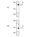
制御部26は、磁性体粒子にゲル層108を通過させる際に、磁力源8をゆっくりと下方へ移動させる。このとき、図2(A)及び(B)に示されているように、ゲル層108のゲルが磁性体粒子とともに処理液層104へ侵入し、処理液層104内の内側壁面に付着することが多い。処理液層104内の内側壁面にゲルが付着している範囲内で磁力源8を素早く動作させると、磁性体粒子が処理液層104内に侵入したゲルに捕捉される虞がある。そこで、制御部26は、処理液層104内において目的成分に対する所定の処理を実施する際、処理液層104内において磁性体粒子をゲルに捕捉されにくくする動作を磁力源8が行なうように、ステッピングモータ14の動作を制御する。
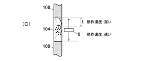
処理液層104内において磁性体粒子をゲルに捕捉されにくくする磁力源8の動作の一例として、図2(A)及び(B)の動作の続きとして示されている図3(C)のように、ゲル層108から一定距離Lの範囲内での磁力源8の動作速度を、ゲル層108から一定距離Lよりも大きく離れた範囲内におけるものよりも遅くすることが挙げられる。ゲル層108から一定距離Lの範囲内での磁力源8の動作速度は、一定距離L内に存在するゲルに磁性体粒子を捕捉させないような速度であることが好ましく、例えば、ゲル層108から一定距離Lよりも大きく離れた範囲内における動作速度の半分以下の速度である。
この場合、ゲル層108からの一定距離Lは、磁性体粒子にゲル層108を通過させる際に処理液層104へゲルが侵入し得る距離以上の距離であってよい。そうすれば、処理液層104にて磁性体粒子に運動させる際に、磁性体粒子が処理液層104内に侵入したゲルに捕捉されることを低減でき、目的成分の回収率の低下を防止できる。
また、処理液層104内において磁性体粒子をゲルに捕捉されにくくする磁力源8の動作の他の例として、図2(A)及び(B)の動作の続きとして示されている図4(C)’のように、ゲル層108から一定距離Lよりも大きく離れた範囲内においてのみ磁力源8を動作させることが挙げられる。すなわち、磁力源8の往復動の上死点は、ゲル層108から一定距離Lよりも大きく離れた位置である。
この場合も、ゲル層108からの一定距離Lは、磁性体粒子にゲル層108を通過させる際に処理液層104へゲルが侵入し得る距離以上の距離であってよい。そうすれば、処理液層104にて磁性体粒子に運動させる際に、磁性体粒子が処理液層104内に侵入したゲルに捕捉されることを低減でき、目的成分の回収率の低下を防止できる。
なお、ゲル層108から一定距離Lよりも大きく離れた範囲内においてのみ磁力源8を動作させる場合に、ゲル層108に近い領域での磁力源8の動作速度を他の領域での動作速度よりも遅くしてもよい。そうすれば、万が一、磁力源8の動作範囲内にゲルが存在する場合でも、磁性体粒子がゲルに捕捉されることを抑制できる。
制御部26は、処理液層104内において目的成分に対する所定の処理を実施する際、磁力源8が図3(C)又は図4(C)’に示されているような動作を行なうように、ステッピングモータ14の動作を制御する。
ここで、磁性体粒子操作デバイス100の各処理液層104とゲル層108との境界の位置は規格化されており、制御部26は各処理液層104とゲル層108との境界位置がどこにあるかを予め把握している。
磁性体粒子にゲル層108を通過させる際に処理液層104へゲルが侵入し得る距離は、実験によりある程度把握することができる。したがって、予め実験的により把握された侵入距離を考慮した距離Lを制御部26に記憶させておくことで、目的成分の回収率を低下させずに所定の処理を実施することができる。
また、図5に示されているように、光の反射率や透過率の変化により処理液層104内に侵入したゲルの端部を光学的に検知する検知部30を設けてもよい。この場合、制御部26は、磁性体粒子にゲル層108を通過させた後、検知部30によって処理液層104内に侵入したゲルの端部の位置を検知し、その位置に基づいてゲル層108からの一定距離Lを割り出すように構成されることが好ましい。その場合、制御部26は、検知部30を用いて割り出した一定距離Lを用いて、処理液層104内において磁性体粒子に運動させる際に、図3(C)又は図4(C)’に示されているような動作を磁力源8に行なわせるように構成することができる。そうすれば、処理液層104内に侵入したゲルに磁性体粒子が捕捉されることを確実に低減することができ、目的成分の回収率の低下を防止できる。
2 前面パネル
4 窪み
6 開口
8 磁力源
10 保持ブロック
12 ボールネジ
14 ステッピングモータ
16 カバー
18 押圧板
20 弾性部材
22 マイクロセンサ
24 ピン
26 制御部
100 磁性体粒子操作デバイス
102 試料層
104 処理液層
106 溶出液層
108 ゲル層
4 窪み
6 開口
8 磁力源
10 保持ブロック
12 ボールネジ
14 ステッピングモータ
16 カバー
18 押圧板
20 弾性部材
22 マイクロセンサ
24 ピン
26 制御部
100 磁性体粒子操作デバイス
102 試料層
104 処理液層
106 溶出液層
108 ゲル層
Claims (16)
- 管状容器内に前記管状容器の長手方向に処理液層とゲル層とが重層されている磁性体粒子操作デバイス内の磁性体粒子を前記磁性体粒子操作デバイスの外側から磁力源により操作する方法であって、
前記磁性体粒子に前記ゲル層を通過させた後、そのゲル層に隣接する前記処理液層内において前記磁性体粒子に運動させるために前記磁力源を前記管状容器の長手方向に沿って自動的に動作させる際に、前記磁性体粒子が通過した前記ゲル層から一定距離の範囲内における前記磁力源の動作速度を前記ゲル層から前記一定距離よりも大きく離れた範囲内における前記磁力源の動作速度よりも遅くする、方法。 - 前記一定距離の範囲内における前記磁力源の動作速度は、前記一定距離の範囲内に存在するゲルに前記磁性体粒子を捕捉させない速度である、請求項1に記載の方法。
- 管状容器内に前記管状容器の長手方向に処理液層とゲル層とが重層されている磁性体粒子操作デバイス内の磁性体粒子を前記磁性体粒子操作デバイスの外側から磁力源により操作する方法であって、
前記磁性体粒子に前記ゲル層を通過させた後、そのゲル層に隣接する前記処理液層内において前記磁性体粒子に運動させる際に、前記磁性体粒子が通過した前記ゲル層から一定距離よりも大きく離れた範囲内において前記磁力源を前記管状容器の長手方向に沿って自動的に動作させる、方法。 - 前記処理液層内における前記磁力源の動作範囲のうち前記ゲル層に最も近い一定範囲における前記磁力源の動作速度を前記動作範囲のうちの前記一定範囲以外の範囲における前記磁力源の動作速度よりも遅くする、請求項3に記載の方法。
- 前記一定距離は、前記磁性体粒子が前記ゲル層を通過する際に前記ゲル層のゲルが前記処理液層内へ侵入した距離以上の距離である、請求項1から4のいずれか一項に記載の方法。
- 前記一定距離は予め実験により求められた距離である、請求項5に記載の方法。
- 前記処理液層内へ侵入したゲルの端部を光学的に検出することにより、前記一定距離を取得する、請求項5に記載の方法。
- 前記磁性体粒子操作デバイスは、前記処理液層と前記ゲル層とが前記管状容器内において交互に重層されているものである、請求項1から7のいずれか一項に記載の方法。
- 管状容器内に前記管状容器の長手方向に処理液層とゲル層とが重層されている磁性体粒子操作デバイス内の磁性体粒子を前記磁性体粒子操作デバイスの外側から操作するための装置であって、
前記磁性体粒子操作デバイス内の前記磁性体粒子に対して作用させる磁力を発する磁力源と、
前記磁力源を前記磁性体粒子操作デバイスの前記管状容器の長手方向に沿って移動させる移動機構と、
前記移動機構の動作を制御する制御部であって、前記磁性体粒子に前記ゲル層を通過させた後、そのゲル層に隣接する前記処理液層内において前記磁性体粒子に運動させるために前記磁力源を前記管状デバイスの長手方向に動作させ、かつ、前記磁性体粒子が通過した前記ゲル層から一定距離の範囲内における前記磁力源の動作速度を前記ゲル層から前記一定距離よりも大きく離れた範囲内における前記磁力源の動作速度よりも遅くするように構成された制御部と、を備えている装置。 - 前記一定距離の範囲内における前記磁力源の動作速度は、前記一定距離の範囲内に存在するゲルに前記磁性体粒子を捕捉させない速度である、請求項8に記載の装置。
- 管状容器内に前記管状容器の長手方向に処理液層とゲル層とが重層されている磁性体粒子操作デバイス内の磁性体粒子を前記磁性体粒子操作デバイスの外側から操作するための装置であって、
前記磁性体粒子操作デバイス内の前記磁性体粒子に対して作用させる磁力を発する磁力源と、
前記磁力源を前記磁性体粒子操作デバイスの前記管状容器の長手方向に沿って移動させる移動機構と、
前記移動機構の動作を制御する制御部であって、前記磁性体粒子に前記ゲル層を通過させた後、そのゲル層に隣接する前記処理液層内において前記磁性体粒子に運動させる際に、前記磁性体粒子が通過した前記ゲル層から一定距離よりも大きく離れた範囲内において前記磁力源を動作させるように構成された制御部と、を備えている装置。 - 前記制御部は、前記処理液層内における前記磁力源の動作範囲のうち前記ゲル層に最も近い一定範囲における前記磁力源の動作速度を前記動作範囲のうちの前記一定範囲以外の範囲における前記磁力源の動作速度よりも遅くするように構成されている、請求項10に記載の方法。
- 前記一定距離は、前記磁性体粒子が前記ゲル層を通過する際に前記ゲル層のゲルが前記処理液層内へ侵入した距離以上の距離である、請求項8から11のいずれか一項に記載の装置。
- 前記一定距離は予め設定されたものである。請求項13に記載の装置。
- 前記処理液層内へ侵入したゲルの端部を光学的に検出する検知部をさらに備え、
前記制御部は、前記検知部により検知された前記ゲルの端部の位置に基づいて前記一定距離を取得するように構成されている、請求項12に記載の装置。 - 前記磁性体粒子操作デバイスは、前記処理液層と前記ゲル層とが前記管状容器内において交互に重層されているものである、請求項9から15のいずれか一項に記載の装置。
Priority Applications (4)
| Application Number | Priority Date | Filing Date | Title |
|---|---|---|---|
| CN201880098707.7A CN112912170A (zh) | 2018-11-22 | 2018-11-22 | 磁性粒子的操作方法及装置 |
| PCT/JP2018/043106 WO2020105159A1 (ja) | 2018-11-22 | 2018-11-22 | 磁性体粒子の操作方法及び装置 |
| JP2020557094A JP7334745B2 (ja) | 2018-11-22 | 2018-11-22 | 磁性体粒子の操作方法及び装置 |
| US17/292,941 US12163123B2 (en) | 2018-11-22 | 2018-11-22 | Method and device for manipulating magnetic particles |
Applications Claiming Priority (1)
| Application Number | Priority Date | Filing Date | Title |
|---|---|---|---|
| PCT/JP2018/043106 WO2020105159A1 (ja) | 2018-11-22 | 2018-11-22 | 磁性体粒子の操作方法及び装置 |
Publications (1)
| Publication Number | Publication Date |
|---|---|
| WO2020105159A1 true WO2020105159A1 (ja) | 2020-05-28 |
Family
ID=70774468
Family Applications (1)
| Application Number | Title | Priority Date | Filing Date |
|---|---|---|---|
| PCT/JP2018/043106 Ceased WO2020105159A1 (ja) | 2018-11-22 | 2018-11-22 | 磁性体粒子の操作方法及び装置 |
Country Status (4)
| Country | Link |
|---|---|
| US (1) | US12163123B2 (ja) |
| JP (1) | JP7334745B2 (ja) |
| CN (1) | CN112912170A (ja) |
| WO (1) | WO2020105159A1 (ja) |
Cited By (1)
| Publication number | Priority date | Publication date | Assignee | Title |
|---|---|---|---|---|
| JP2020110741A (ja) * | 2019-01-08 | 2020-07-27 | 株式会社島津製作所 | 磁性粒子操作装置 |
Citations (5)
| Publication number | Priority date | Publication date | Assignee | Title |
|---|---|---|---|---|
| JPS63108265A (ja) * | 1986-10-25 | 1988-05-13 | Nippon Telegr & Teleph Corp <Ntt> | レ−ザ磁気免疫測定方法 |
| JP2014221061A (ja) * | 2010-12-21 | 2014-11-27 | 株式会社島津製作所 | 管内で対象成分を操作するための操作管 |
| WO2015113047A2 (en) * | 2014-01-27 | 2015-07-30 | Brevitest Technologies, Llc | Discontinuous fluidic systems for point-of-care analyte measurement |
| WO2016079779A1 (ja) * | 2014-11-17 | 2016-05-26 | 株式会社島津製作所 | 粒子操作方法および粒子操作用装置 |
| JP2016117032A (ja) * | 2014-12-22 | 2016-06-30 | 株式会社島津製作所 | 磁性体粒子操作用装置 |
Family Cites Families (4)
| Publication number | Priority date | Publication date | Assignee | Title |
|---|---|---|---|---|
| ES2388110T3 (es) * | 2006-12-12 | 2012-10-09 | Koninklijke Philips Electronics N.V. | Dispositivo de sensor microelectrónico para detectar partículas de marcador |
| JP5678565B2 (ja) * | 2009-12-08 | 2015-03-04 | Jnc株式会社 | 磁性微粒子およびその製造方法 |
| JP6323550B2 (ja) * | 2014-05-23 | 2018-05-16 | 株式会社島津製作所 | 磁性体粒子の操作方法 |
| CN205420433U (zh) * | 2016-03-14 | 2016-08-03 | 郭亮甫 | 磁性吸附转移棒 |
-
2018
- 2018-11-22 US US17/292,941 patent/US12163123B2/en active Active
- 2018-11-22 JP JP2020557094A patent/JP7334745B2/ja active Active
- 2018-11-22 WO PCT/JP2018/043106 patent/WO2020105159A1/ja not_active Ceased
- 2018-11-22 CN CN201880098707.7A patent/CN112912170A/zh active Pending
Patent Citations (5)
| Publication number | Priority date | Publication date | Assignee | Title |
|---|---|---|---|---|
| JPS63108265A (ja) * | 1986-10-25 | 1988-05-13 | Nippon Telegr & Teleph Corp <Ntt> | レ−ザ磁気免疫測定方法 |
| JP2014221061A (ja) * | 2010-12-21 | 2014-11-27 | 株式会社島津製作所 | 管内で対象成分を操作するための操作管 |
| WO2015113047A2 (en) * | 2014-01-27 | 2015-07-30 | Brevitest Technologies, Llc | Discontinuous fluidic systems for point-of-care analyte measurement |
| WO2016079779A1 (ja) * | 2014-11-17 | 2016-05-26 | 株式会社島津製作所 | 粒子操作方法および粒子操作用装置 |
| JP2016117032A (ja) * | 2014-12-22 | 2016-06-30 | 株式会社島津製作所 | 磁性体粒子操作用装置 |
Cited By (2)
| Publication number | Priority date | Publication date | Assignee | Title |
|---|---|---|---|---|
| JP2020110741A (ja) * | 2019-01-08 | 2020-07-27 | 株式会社島津製作所 | 磁性粒子操作装置 |
| JP7147564B2 (ja) | 2019-01-08 | 2022-10-05 | 株式会社島津製作所 | 磁性粒子操作装置 |
Also Published As
| Publication number | Publication date |
|---|---|
| JP7334745B2 (ja) | 2023-08-29 |
| US20220002709A1 (en) | 2022-01-06 |
| JPWO2020105159A1 (ja) | 2021-10-07 |
| US12163123B2 (en) | 2024-12-10 |
| CN112912170A (zh) | 2021-06-04 |
Similar Documents
| Publication | Publication Date | Title |
|---|---|---|
| EP3742347B1 (en) | Deep machine learning methods and apparatus for robotic grasping | |
| CN107433373B (zh) | 线放电加工系统 | |
| JP7234393B2 (ja) | 容器および検査キット | |
| CN109153016A (zh) | 微流体中的磁导管 | |
| US8371743B2 (en) | Method for suspending or re-suspending particles in a solution and apparatus adapted thereto | |
| RU2713490C2 (ru) | Сборка-мишень и система производства изотопов с вибрационным устройством | |
| US9841419B2 (en) | Sensor device and a method of sampling | |
| JP7334745B2 (ja) | 磁性体粒子の操作方法及び装置 | |
| US8512459B2 (en) | Pre-concentration device and method for ion mobility detection apparatus | |
| US20130319087A1 (en) | Bubble reduction device, chromatography device, bubble reduction method, and bubble reduction program | |
| WO2020008463A2 (en) | System, apparatus and method for computerized automatic diagnosis | |
| JP7522537B2 (ja) | 磁性粒子操作装置 | |
| US12201994B2 (en) | Magnetic particle manipulating apparatus | |
| CN114341648B (zh) | 用于在阀门处捕获流体的系统和方法 | |
| KR20200115350A (ko) | 액추에이터 지원형 위치 결정 시스템 및 방법 | |
| US20220399180A1 (en) | Sample Delivery, Data Acquisition, and Analysis, and Automation Thereof, in Charged-Particle-Beam Microscopy | |
| JP7147564B2 (ja) | 磁性粒子操作装置 | |
| US10168258B2 (en) | Sample holder for acoustic treatment | |
| JP5063481B2 (ja) | 生体試料分析装置に用いられる誤作動防止機構 | |
| JPWO2019187293A1 (ja) | 分離装置及び分離方法 | |
| WO2020129365A1 (ja) | 磁性体粒子操作デバイス | |
| CN1837796A (zh) | 荧光x射线分析仪、荧光x射线分析方法及分析程序 | |
| KR20150072617A (ko) | 희토류가 함유된 나노파티클 포집장치 | |
| JP2023039620A (ja) | 回収装置および回収方法 | |
| KR20150139355A (ko) | 중금속 이온 샘플 전처리용 미세 유체 칩 및 이를 이용하는 중금속 이온 샘플 전처리 장치와 방법 |
Legal Events
| Date | Code | Title | Description |
|---|---|---|---|
| 121 | Ep: the epo has been informed by wipo that ep was designated in this application |
Ref document number: 18940737 Country of ref document: EP Kind code of ref document: A1 |
|
| ENP | Entry into the national phase |
Ref document number: 2020557094 Country of ref document: JP Kind code of ref document: A |
|
| NENP | Non-entry into the national phase |
Ref country code: DE |
|
| 122 | Ep: pct application non-entry in european phase |
Ref document number: 18940737 Country of ref document: EP Kind code of ref document: A1 |