WO2020105110A1 - 変倍光学系、光学機器、および変倍光学系の製造方法 - Google Patents
変倍光学系、光学機器、および変倍光学系の製造方法Info
- Publication number
- WO2020105110A1 WO2020105110A1 PCT/JP2018/042793 JP2018042793W WO2020105110A1 WO 2020105110 A1 WO2020105110 A1 WO 2020105110A1 JP 2018042793 W JP2018042793 W JP 2018042793W WO 2020105110 A1 WO2020105110 A1 WO 2020105110A1
- Authority
- WO
- WIPO (PCT)
- Prior art keywords
- lens group
- negative lens
- optical system
- negative
- positive
- Prior art date
- Legal status (The legal status is an assumption and is not a legal conclusion. Google has not performed a legal analysis and makes no representation as to the accuracy of the status listed.)
- Ceased
Links
Images






Classifications
-
- G—PHYSICS
- G02—OPTICS
- G02B—OPTICAL ELEMENTS, SYSTEMS OR APPARATUS
- G02B27/00—Optical systems or apparatus not provided for by any of the groups G02B1/00 - G02B26/00, G02B30/00
- G02B27/64—Imaging systems using optical elements for stabilisation of the lateral and angular position of the image
- G02B27/646—Imaging systems using optical elements for stabilisation of the lateral and angular position of the image compensating for small deviations, e.g. due to vibration or shake
-
- G—PHYSICS
- G02—OPTICS
- G02B—OPTICAL ELEMENTS, SYSTEMS OR APPARATUS
- G02B13/00—Optical objectives specially designed for the purposes specified below
- G02B13/001—Miniaturised objectives for electronic devices, e.g. portable telephones, webcams, PDAs, small digital cameras
- G02B13/0015—Miniaturised objectives for electronic devices, e.g. portable telephones, webcams, PDAs, small digital cameras characterised by the lens design
- G02B13/002—Miniaturised objectives for electronic devices, e.g. portable telephones, webcams, PDAs, small digital cameras characterised by the lens design having at least one aspherical surface
- G02B13/0045—Miniaturised objectives for electronic devices, e.g. portable telephones, webcams, PDAs, small digital cameras characterised by the lens design having at least one aspherical surface having five or more lenses
-
- G—PHYSICS
- G02—OPTICS
- G02B—OPTICAL ELEMENTS, SYSTEMS OR APPARATUS
- G02B13/00—Optical objectives specially designed for the purposes specified below
- G02B13/02—Telephoto objectives, i.e. systems of the type + - in which the distance from the front vertex to the image plane is less than the equivalent focal length
-
- G—PHYSICS
- G02—OPTICS
- G02B—OPTICAL ELEMENTS, SYSTEMS OR APPARATUS
- G02B15/00—Optical objectives with means for varying the magnification
- G02B15/14—Optical objectives with means for varying the magnification by axial movement of one or more lenses or groups of lenses relative to the image plane for continuously varying the equivalent focal length of the objective
- G02B15/145—Optical objectives with means for varying the magnification by axial movement of one or more lenses or groups of lenses relative to the image plane for continuously varying the equivalent focal length of the objective having five groups only
- G02B15/1451—Optical objectives with means for varying the magnification by axial movement of one or more lenses or groups of lenses relative to the image plane for continuously varying the equivalent focal length of the objective having five groups only the first group being positive
- G02B15/145105—Optical objectives with means for varying the magnification by axial movement of one or more lenses or groups of lenses relative to the image plane for continuously varying the equivalent focal length of the objective having five groups only the first group being positive arranged +-+--
-
- G—PHYSICS
- G02—OPTICS
- G02B—OPTICAL ELEMENTS, SYSTEMS OR APPARATUS
- G02B15/00—Optical objectives with means for varying the magnification
- G02B15/14—Optical objectives with means for varying the magnification by axial movement of one or more lenses or groups of lenses relative to the image plane for continuously varying the equivalent focal length of the objective
- G02B15/16—Optical objectives with means for varying the magnification by axial movement of one or more lenses or groups of lenses relative to the image plane for continuously varying the equivalent focal length of the objective with interdependent non-linearly related movements between one lens or lens group, and another lens or lens group
- G02B15/20—Optical objectives with means for varying the magnification by axial movement of one or more lenses or groups of lenses relative to the image plane for continuously varying the equivalent focal length of the objective with interdependent non-linearly related movements between one lens or lens group, and another lens or lens group having an additional movable lens or lens group for varying the objective focal length
Definitions
- the first aspect of the present invention is A first positive lens group having a positive refractive power arranged closest to the object side, a first negative lens group having a negative refractive power arranged on the image side of the first positive lens group, and the first negative lens group A plurality of lens groups including a second negative lens group having a negative refractive power and arranged on the image side of the lens group; The distance between adjacent lens groups changes during zooming, The first negative lens group is movable so as to include a component in a direction orthogonal to the optical axis as a vibration isolation lens group, The second negative lens group moves along the optical axis when focused, The first negative lens group is a variable power optical system further having a lens that satisfies the following conditional expression. 1.910 ⁇ nd1n However, nd1n: Refractive index for d line (wavelength 587.6 nm)
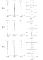
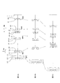
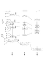
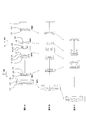
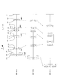
- 1A, 1B, and 1C are cross-sectional views of the variable power optical system according to Example 1 in the wide-angle end state, the intermediate focal length state, and the telephoto end state, respectively.
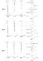
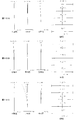
- 2A, 2B, and 2C are aberration diagrams of the variable power optical system according to Example 1 upon focusing on an object at infinity in the wide-angle end state, the intermediate focal length state, and the telephoto end state, respectively.
- 3A, 3B, and 3C are cross-sectional views of the variable power optical system according to the second example in a wide-angle end state, an intermediate focal length state, and a telephoto end state, respectively.
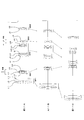
- 7A, 7B, and 7C are cross-sectional views of the variable power optical system according to the fourth example in a wide-angle end state, an intermediate focal length state, and a telephoto end state, respectively.
- 8A, 8B, and 8C are graphs showing various aberrations of the variable power optical system according to Example 4 upon focusing on an object at infinity in the wide-angle end state, the intermediate focal length state, and the telephoto end state, respectively.
- 9A, 9B, and 9C are cross-sectional views of the variable power optical system according to the fifth example in a wide-angle end state, an intermediate focal length state, and a telephoto end state, respectively.
- 10A, 10B and 10C are graphs showing various aberrations of the variable power optical system according to Example 5 upon focusing on an object at infinity in a wide-angle end state, an intermediate focal length state, and a telephoto end state, respectively.
- 11A, 11B, and 11C are cross-sectional views of the variable power optical system according to Example 6 in the wide-angle end state, intermediate focal length state, and telephoto end state, respectively.
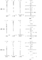
- 12A, 12B, and 12C are aberration diagrams of the variable power optical system according to the sixth example upon focusing on an object at infinity in the wide-angle end state, the intermediate focal length state, and the telephoto end state, respectively.
- FIG. 13A, 13B, and 13C are cross-sectional views of the variable power optical system according to the seventh example in a wide-angle end state, an intermediate focal length state, and a telephoto end state, respectively.
- 14A, 14B, and 14C are aberration diagrams of the variable power optical system according to Example 7 upon focusing on an object at infinity in the wide-angle end state, the intermediate focal length state, and the telephoto end state, respectively.
- FIG. 15 is a diagram showing a configuration of a camera including a variable power optical system.
- FIG. 16 is a flowchart showing the outline of the method of manufacturing the variable power optical system.
- variable power optical system of the present embodiment has a first positive lens unit having a positive refractive power arranged closest to the object side and a first positive lens unit having a negative refractive power arranged on the image side of the first positive lens unit. It has a plurality of lens groups including one negative lens group and a second negative lens group having a negative refractive power and arranged on the image side of the first negative lens group.
- the distance changes and the first negative lens group is movable so as to include a component in a direction orthogonal to the optical axis as a vibration reduction lens group, and the second negative lens group is moved along the optical axis during focusing.
- the first negative lens group further has a lens that satisfies the following conditional expression. (1) 1.910 ⁇ nd1n However, nd1n: Refractive index for d line (wavelength 587.6 nm)
- the second negative lens group moves along the optical axis at the time of focusing.
- the second negative lens group arranged on the image side as the focusing lens group in this way, a change in image magnification is suppressed, and the ratio of the amount of change in the image plane to the movement of the second negative lens group during focusing is adjusted. Can be large.
- the conditional expression (1) is a conditional expression for defining the refractive index of at least one lens among the lenses forming the first negative lens group.
- the variable power optical system of the present embodiment can satisfactorily correct astigmatism and field curvature by using a glass material whose first negative lens group satisfies the conditional expression (1).
- variable power optical system of the present embodiment satisfies the following conditional expression (2).
- (2) 0.200 ⁇ (-f1n) / ⁇ (fw * ft) ⁇ 0.400
- f1n focal length of the first negative lens group
- fw focal length of the entire zoom optical system in the wide-angle end state
- ft focal length of the entire zoom optical system in the telephoto end state
- Conditional expression (2) defines an appropriate range for the ratio of the focal length of the first negative lens unit to the geometric mean value of the focal lengths of the variable power optical system in the wide-angle end state and the telephoto end state. Is a conditional expression for doing so.
- conditional expression (2) by satisfying conditional expression (2), the lateral magnification of the first negative lens group becomes an appropriate value, the influence of camera shake or the like is suppressed during image stabilization, and image blurring is suppressed. It can be corrected well.
- conditional expression (2) of the variable power optical system of the present embodiment falls below the lower limit value, it becomes difficult to correct coma and astigmatism. Further, since the focal length of the first negative lens group is shortened, the lateral magnification of the first negative lens group is changed, and the influence on the image shift due to the change in the direction vertical to the optical axis becomes large.
- the lower limit values of conditional expression (2) are set to 0.220, 0.230, 0.235, 0.240, 0.245, 0.250, 0. It is preferably 255, 0.260, 0.265, and more preferably 0.270.
- variable power optical system of the present embodiment satisfies the following conditional expression (3).
- (3) 0.200 ⁇ (-f2n) / ⁇ (fw * ft) ⁇ 1.000
- f2n focal length of the second negative lens group
- fw focal length of the entire zoom optical system in the wide-angle end state
- ft focal length of the entire zoom optical system in the telephoto end state
- Conditional expression (3) defines an appropriate range for the ratio of the focal length of the second negative lens unit and the geometric mean value of the focal lengths of the variable power optical system in the wide-angle end state and the telephoto end state. Is a conditional expression for doing so.
- the variable power optical system of the present embodiment can satisfactorily correct various aberrations during focusing and can be downsized.
- the corresponding value of the conditional expression (3) of the variable power optical system of the present embodiment falls below the lower limit value, the focal length of the second negative lens group becomes short, so that the field curvature generated in the second negative lens group.
- the aberration becomes large, and it becomes difficult to correct the aberration when focusing.
- the lower limit values of conditional expression (3) are set to 0.300, 0.350, 0.400, 0.425, 0.450, 0.475, 0. It is preferably 500, 0.510, 0.520, and more preferably 0.530.
- variable power optical system of the present embodiment satisfies the following conditional expression (4).
- ⁇ 1nt lateral magnification of the first negative lens group in the telephoto end state
- ⁇ 2nt lateral magnification of the second negative lens group in the telephoto end state
- Conditional expression (4) is a conditional expression for defining an appropriate range for the ratio of the lateral magnification of the first negative lens group in the telephoto end state to the lateral magnification of the second negative lens group in the telephoto end state. ..
- the variable power optical system of the present embodiment can suppress the occurrence of spherical aberration and image plane distortion in the first negative lens group and the second negative lens group.
- the corresponding value of the conditional expression (4) of the variable power optical system of the present embodiment is less than the lower limit value, the focal length of the second negative lens group becomes short, so that the field curvature generated in the second negative lens group.
- the aberration becomes large, and it becomes difficult to correct the aberration when focusing.
- the lower limit values of conditional expression (4) are set to -0.950, -0.925, -0.900, -0.880, -0.860,-. It is preferably 0.850, -0.840, -0.825, -0.810, and further -0.800.
- Conditional expression (5) is an amount of movement of the first negative lens unit at the time of zooming from the wide-angle end state to the telephoto end state when the direction of movement to the image side is the positive direction, and the zooming optical system. Is a conditional expression for defining an appropriate range for the ratio of the geometrical mean value of the focal length in the wide-angle end state and the focal length in the telephoto end state.
- the variable power optical system of the present embodiment can favorably correct spherical aberration and image plane distortion by satisfying conditional expression (5).
- the focal length of the first negative lens group becomes long, so that the moving amount of the first negative lens group at the time of variable power changes.
- the spherical aberration and the distortion of the image plane become large.
- the focal length of the other lens group becomes short and the spherical aberration generated in the other lens group becomes large.
- the upper limit values of conditional expression (5) are set to 0.230, 0.220, 0.210, 0.200, 0.195, 0.190, 0. 185, 0.180, 0.175, and more preferably 0.170.
- the corresponding value of the conditional expression (5) of the variable power optical system of the present embodiment is less than the lower limit value, the focal length of the first negative lens group becomes short, so spherical aberration generated in the first negative lens group and The field curvature aberration becomes large.
- the lower limit values of conditional expression (5) are set to 0.070, 0.080, 0.090, 0.095, 0.100, 0.105, 0. It is preferably 110, 0.115, 0.120, and more preferably 0.125.
- variable power optical system of the present embodiment it is desirable that the first negative lens group has, in order from the object side, a first negative lens, a second negative lens, and a positive lens.
- the variable power optical system of the present embodiment can prevent light rays outside the angle of view from undergoing multiple reflection and reaching the image pickup surface.
- variable power optical system of the present embodiment it is desirable that the second negative lens group includes a positive lens and a negative lens. With this configuration, the variable power optical system of the present embodiment can suppress the occurrence of chromatic aberration and field curvature aberration when focusing on a very close distance.
- variable power optical system of the present embodiment it is desirable that an aperture stop is arranged between the first negative lens group and the second negative lens group. As described above, by disposing the negative lens group after the aperture stop, the variable power optical system of the present embodiment can suppress the fluctuation of the angle of view during focusing.
- variable power optical system of the present embodiment is arranged such that the first positive lens group, the first negative lens group, the second positive lens group having a positive refractive power, and the second negative lens group are arranged in this order from the object side. It is desirable to have a lens group. As a result, the variable power optical system of the present embodiment is small in size and can realize high optical performance capable of favorably correcting various aberrations.
- variable power optical system of the present embodiment is arranged such that the first positive lens group, the first negative lens group, the second positive lens group having a positive refractive power, and the second negative lens group are arranged in this order from the object side. It is desirable to have a lens group and satisfy the following conditional expression (6). (6) 0.500 ⁇ f2p / (-f1n) ⁇ 1.500 However, f2p: focal length of the second positive lens group f1n: focal length of the first negative lens group
- variable power optical system of the present embodiment includes, in order from the object side, the first positive lens group, the first negative lens group, the second positive lens group having a positive refractive power, and the second negative lens group.
- the focal length of the first negative lens group becomes short, and the spherical aberration and the field curvature generated in the first negative lens group. Aberration becomes large.
- the upper limit values of the conditional expression (6) are set to 1.400, 1.360, 1.330, 1.300, 1.275, 1.250, 1. It is preferably 225, 1.200, 1.175, and more preferably 1.150.
- the focal length of the first negative lens group becomes long, and therefore the movement of the first negative lens group during zooming.
- the amount becomes large, and the fluctuations of spherical aberration and field curvature aberration become large.
- the focal length of the second positive lens group becomes short, the spherical aberration generated in the second positive lens group becomes large.
- the lower limit values of conditional expression (6) are set to 0.700, 0.750, 0.800, 0.850, 0.875, 0.900, 0. It is preferably set to 925, 0.950, 0.975, or 1.000.
- variable power optical system of the present embodiment is arranged such that the first positive lens group, the first negative lens group, the second positive lens group having a positive refractive power, and the second negative lens group are arranged in this order from the object side. It is desirable to have a lens group and satisfy the following conditional expression (7).
- X2p The amount of movement of the second positive lens group during zooming from the wide-angle end state to the telephoto end state when the direction of movement to the image side is the positive direction
- fw The zooming optical system in the wide-angle end state
- Focal length ft of the whole system Focal length of the whole system of the variable power optical system in the telephoto end state
- variable power optical system of the present embodiment includes, in order from the object side, the first positive lens group, the first negative lens group, the second positive lens group having a positive refractive power, and the second negative lens group.
- Conditional expression (7) is an amount of movement of the second positive lens unit at the time of zooming from the wide-angle end state to the telephoto end state when the direction of movement to the image side is the positive direction, and the zooming optical system. Is a conditional expression for defining an appropriate range for the ratio of the geometrical mean value of the focal length in the wide-angle end state and the focal length in the telephoto end state.
- the variable power optical system of the present embodiment can satisfactorily correct various aberrations including coma by satisfying the conditional expression (7).
- the upper limit of conditional expression (7) is set to -0.030, -0.040, -0.050, -0.060, -0.070,-. It is preferably 0.080, -0.090, -0.100, -0.110, and more preferably -0.120.
- conditional expression (7) of the variable power optical system of the present embodiment falls below the lower limit value
- the power of the second positive lens group becomes strong, and spherical aberration is excessively corrected in the telephoto end state. ..
- the lower limit values of conditional expression (7) are set to ⁇ 0.280, ⁇ 0.270, ⁇ 0.260, ⁇ 0.250, ⁇ 0.240, ⁇ It is preferably 0.230, -0.220, -0.210, -0.205, and more preferably -0.200.
- variable power optical system of the present embodiment is arranged such that the first positive lens group, the first negative lens group, the second positive lens group having a positive refractive power, and the second negative lens group are arranged in this order from the object side. It is desirable that the first positive lens group has a lens group and moves during zooming. With this configuration, the variable power optical system of the present embodiment suppresses fluctuations in spherical aberration and field curvature aberration during variable power, enables efficient variable power, and realizes miniaturization.
- variable power optical system of the present embodiment satisfies the following conditional expression (8).
- (8) 0.150 ⁇ Bfaw / fw ⁇ 0.500
- Bfaw Air-converted back focus of the entire zoom optical system in the wide-angle end state
- fw Focal length of the entire zoom optical system in the aperture end state
- Conditional expression (8) defines an appropriate range for the ratio between the air-converted back focus of the entire zoom optical system in the wide-angle end state and the focal length of the entire zoom optical system in the wide-angle end state. Is a conditional expression of.
- the variable power optical system of the present embodiment can favorably correct various aberrations such as coma in the wide-angle end state.
- conditional expression (8) of the variable power optical system of the present embodiment exceeds the upper limit value, the air-equivalent back focus becomes too large for the focal length of the variable power optical system in the wide-angle end state, so that the wide-angle end is increased. It becomes difficult to correct various aberrations such as coma in the state.
- the upper limit values of conditional expression (8) are set to 0.460, 0.450, 0.440, 0.420, 0.400, 0.390, 0. It is preferably 380, 0.370, and more preferably 0.360.
- the corresponding value of the conditional expression (8) for the variable power optical system of the present embodiment is less than the lower limit value, the back focus becomes too small with respect to the focal length of the variable power optical system in the wide-angle end state, so It becomes difficult to correct various aberrations such as coma in the state.
- the lower limit of conditional expression (8) is set to 0.170, 0.180, 0.190, 0.200, 0.210, and 0.220. Preferably.
- Conditional expression (9) is a conditional expression for defining an appropriate range of the total angle of view of the variable power optical system in the wide-angle end state.
- the variable power optical system of the present embodiment has a wide angle of view and is able to favorably correct field curvature aberration and distortion.
- the upper limit of conditional expression (9) it is preferable to set the upper limit of conditional expression (9) to 43.000 °. Further, in order to secure the effect of the present embodiment, it is preferable to set the upper limit value of the conditional expression (9) to 40.000 °, 38.000 °, 36.000 °, and further 35.000 °. In order to secure the effect of this embodiment, it is preferable to set the lower limit of conditional expression (9) to 22.000 °. Further, in order to secure the effect of the present embodiment, it is preferable that the lower limit value of conditional expression (9) is set to 24.000 °, 25.000 °, 26.000 °, and further 27.000 °.
- variable power optical system of the present embodiment satisfies the following conditional expression (10). (10) 1.500 ⁇ ( ⁇ 1nt-1) * ⁇ Rt ⁇ 4.500
- ⁇ 1nt Lateral magnification of the first negative lens group in the telephoto end state
- ⁇ Rt Composite lateral magnification of all lens groups arranged closer to the image side than the first negative lens group in the telephoto end state
- Conditional expression (10) is defined by the lateral magnification of the first negative lens group in the telephoto end state and the combined lateral magnification of all the lens groups arranged closer to the image side than the first negative lens group in the telephoto end state. It is a conditional expression for defining an appropriate range for the product.
- the variable power optical system of the present embodiment can favorably correct coma aberration and field curvature aberration by satisfying conditional expression (10). Further, the deterioration of the optical performance when decentered is small, which is preferable.
- conditional expression (10) of the variable power optical system of the present embodiment exceeds the upper limit value, the power of the first negative lens group becomes strong, so that it becomes difficult to correct coma and astigmatism.
- the upper limit of conditional expression (10) are set to 4.300, 4.200, 4.100, 4.000, 3.900, 3.800, 3. It is preferably 700, 3.600, and more preferably 3.500.
- variable power optical system of the present embodiment satisfies the following conditional expression (11).
- (11) 0.500 ⁇ m12tw / fw ⁇ 2.000
- m12tw Amount of change in distance between the first positive lens unit and the first negative lens unit during zooming from the wide-angle end state to the telephoto end state
- fw Focal length of the entire zoom optical system in the wide-angle end state
- Conditional expression (11) is an amount of change in the distance between the first positive lens group and the first negative lens group during zooming from the wide-angle end state to the telephoto end state, and the zooming optical system in the wide-angle end state. This is a conditional expression for defining an appropriate range for the ratio with the focal length of the entire system.
- the variable power optical system of the present embodiment can satisfactorily correct various aberrations such as spherical aberration and chromatic aberration in the telephoto end state.
- the corresponding value of the conditional expression (11) of the variable power optical system of the present embodiment exceeds the upper limit value, the powers of the first positive lens group and the first negative lens group become weak, and it becomes difficult to correct spherical aberration. I will end up. In addition, the total length of the variable power optical system increases.
- the upper limit values of the conditional expression (11) are set to 1.800, 1.700, 1.650, 1.600, 1.550, 1.500, 1.00. It is preferably 450, 1.400, 1.350, and more preferably 1.300.
- conditional expression (11) of the variable power optical system of the present embodiment falls below the lower limit value
- the power of the first positive lens group becomes strong, and it becomes difficult to correct spherical aberration, axial chromatic aberration, and lateral chromatic aberration.
- the lower limit values of conditional expression (11) are set to 0.700, 0.800, 0.850, 0.900, 0.950, 1.000, 1. It is preferably 050, more preferably 1.100.
- variable power optical system of the present embodiment satisfies the following conditional expression (12). (12) 0.150 ⁇ (-f1n) / f1p ⁇ 0.350
- f1n focal length of the first negative lens group
- f1p focal length of the first positive lens group
- the conditional expression (12) is a conditional expression for defining an appropriate range for the ratio of the focal length of the first negative lens group and the focal length of the first positive lens group.
- the variable power optical system of the present embodiment can suppress variations in various aberrations such as spherical aberration during zooming from the wide-angle end state to the telephoto end state. ..
- the corresponding value of the conditional expression (12) of the variable power optical system of the present embodiment is less than the lower limit value, the refractive power of the first negative lens group becomes too strong, so that the spherical aberration at the time of zooming becomes large. It becomes difficult to suppress the variation of various aberrations.
- the lower limit of conditional expression (12) it is preferable to set the lower limit values of the conditional expression (12) to 0.170, 0.180, 0.190, 0.200, and 0.210.
- variable power optical system of the present embodiment is arranged such that the first positive lens group, the first negative lens group, the second positive lens group having a positive refractive power, and the second negative lens group are arranged in this order from the object side. It is desirable to have a lens group and a third negative lens group having a negative refractive power, and to satisfy the following conditional expression (13). (13) 0.010 ⁇ (-f3n) / f1p ⁇ 3.000 However, f3n: focal length of the third negative lens group f1p: focal length of the first positive lens group
- variable power optical system of the present embodiment includes, in order from the object side, the first positive lens group, the first negative lens group, the second positive lens group having a positive refractive power, and the second negative lens group. And the third negative lens group having a negative refractive power, it is possible to realize a small size and high optical performance capable of excellently correcting various aberrations.
- the conditional expression (13) is a conditional expression for defining an appropriate range for the ratio of the focal length of the third negative lens group and the focal length of the first positive lens group.
- the corresponding value of the conditional expression (13) of the variable power optical system of the present embodiment exceeds the upper limit value, the refracting power of the first positive lens unit becomes too strong, and therefore various coma aberrations at the time of variable power are brought about. It becomes difficult to suppress variation in aberration.
- the upper limit values of the conditional expression (13) are set to 2.600, 2.400, 2.200, 2.000, 1.800, 1.700, 1. It is preferably 600, more preferably 1.500.
- the corresponding value of the conditional expression (13) of the variable power optical system of the present embodiment is lower than the lower limit value, the refracting power of the first negative lens unit becomes too strong, and therefore the coma aberration at the time of zooming is reduced. It becomes difficult to suppress the variation of various aberrations.
- the lower limit values of conditional expression (13) are set to 0.100, 0.150, 0.200, 0.250, 0.300, 0.350, 0. It is preferably 400, 0.450, 0.500 or even 0.550.
- variable power optical system of the present embodiment is arranged such that the first positive lens group, the first negative lens group, the second positive lens group having a positive refractive power, and the second negative lens group are arranged in this order from the object side. It is desirable to have a lens group and a third negative lens group having a negative refractive power, and to satisfy the following conditional expression (14). (14) 0.050 ⁇ f2n / f3n ⁇ 1.500 However, f2n: focal length of the second negative lens group f3n: focal length of the third negative lens group
- variable power optical system of the present embodiment includes, in order from the object side, the first positive lens group, the first negative lens group, the second positive lens group having a positive refractive power, and the second negative lens group. And the third negative lens group having a negative refractive power, it is possible to realize a small size and high optical performance capable of excellently correcting various aberrations.
- conditional expression (14) is a conditional expression for defining an appropriate range for the ratio of the focal length of the second negative lens group and the focal length of the third negative lens group.
- the variable power optical system of the present embodiment is capable of satisfactorily correcting various aberrations such as field curvature during zooming from the wide-angle end state to the telephoto end state by satisfying conditional expression (14). You can
- conditional expression (14) of the variable power optical system of the present embodiment exceeds the upper limit value, the refracting power of the third negative lens group becomes too strong. It becomes difficult to satisfactorily correct various aberrations.
- the upper limit of conditional expression (14) is set to 1.300, 1.200, 1.100, 1.000, 0.950, and further 0.900. Preferably.
- the corresponding value of the conditional expression (14) of the variable power optical system of the present embodiment is less than the lower limit value, the refracting power of the second negative lens group becomes too strong, and therefore the field curvature at the time of zooming. It becomes difficult to satisfactorily correct various aberrations including the above.
- the lower limit of conditional expression (14) is set to 0.150, 0.200, 0.225, 0.250, 0.275, 0.290, and 0. It is preferably set to 300.
- variable power optical system of the present embodiment is arranged such that the first positive lens group, the first negative lens group, the second positive lens group having a positive refractive power, and the second negative lens group are arranged in this order from the object side. It is desirable to have a lens group and a third negative lens group having a negative refractive power, and to satisfy the following conditional expression (15). (15) 0.080 ⁇ (RR-RF) / (RR + RF) ⁇ 1.000 However, RR: radius of curvature of lens surface closest to image side of third negative lens group RF: radius of curvature of lens surface closest to object side of third negative lens group
- variable power optical system of the present embodiment includes, in order from the object side, the first positive lens group, the first negative lens group, the second positive lens group having a positive refractive power, and the second negative lens group. And the third negative lens group having a negative refractive power, it is possible to realize a small size and high optical performance capable of excellently correcting various aberrations.
- conditional expression (15) is a conditional expression that defines the shape of the most image-side lens surface of the third negative lens group and the shape of the most object-side lens surface of the third negative lens group.
- the variable power optical system of the present embodiment can satisfactorily correct coma and field curvature in the telephoto end state by satisfying conditional expression (15).
- conditional expression (15) of the variable power optical system of the present embodiment exceeds the upper limit value, it becomes difficult to correct various aberrations such as coma.
- the upper limit values of conditional expression (15) are set to 0.900, 0.850, 0.800, 0.775, 0.750, 0.725, 0. It is preferably 700, 0.690, and more preferably 0.680.
- the lower limit of conditional expression (15) is set to 0.090, 0.095, 0.100, 0.105, 0.110, 0.115, and 0. .120 is preferable.
- variable power optical system of the present embodiment is arranged such that the first positive lens group, the first negative lens group, the second positive lens group having a positive refractive power, and the second negative lens group are arranged in this order from the object side. It is desirable to have a lens group and a third negative lens group having a negative refractive power, and to satisfy the following conditional expression (16). (16) -10.000 ⁇ RF / Bfaw ⁇ -1.500 RF: radius of curvature of the lens surface of the third negative lens group closest to the object side Bfaw: air-converted back focus of the entire zoom optical system in the wide-angle end state
- variable power optical system of the present embodiment includes, in order from the object side, the first positive lens group, the first negative lens group, the second positive lens group having a positive refractive power, and the second negative lens group. And the third negative lens group having a negative refractive power, it is possible to realize a small size and high optical performance capable of excellently correcting various aberrations.
- Conditional expression (16) defines an appropriate range of the ratio of the radius of curvature of the lens surface of the third negative lens group closest to the object side to the air-equivalent back focus of the entire variable-magnification optical system in the wide-angle end state. Is a conditional expression for The variable power optical system of the present embodiment can satisfactorily correct the field curvature by satisfying the conditional expression (16). It is also effective in reducing the generation of ghosts.
- the upper limit of conditional expression (16) is set to -1.700, -1.800, -1.900, -2,000, and -2.100. Preferably.
- the lower limit values of the conditional expression (16) are set to ⁇ 8,000, ⁇ 7,000, ⁇ 6,000, ⁇ 5,500, ⁇ 5.000, ⁇ It is preferably set to 4.500, -4000, and more preferably -3.800.
- the optical device of this embodiment has a variable power optical system having the above-described configuration. As a result, it is possible to realize an optical device in which the optical performance is improved and the vibration-proof lens group is downsized.
- the method of manufacturing a variable power optical system includes a first positive lens unit having a positive refractive power arranged closest to the object side and a negative refractive power arranged on the image side of the first positive lens unit.
- a method of manufacturing a variable power optical system having a plurality of lens groups including a first negative lens group having the following: and a second negative lens group having a negative refractive power and arranged on the image side of the first negative lens group. It is configured such that the distance between adjacent lens groups changes during zooming, and the first negative lens group is configured to be movable so as to include a component in a direction orthogonal to the optical axis as a vibration isolation lens group.
- the second negative lens group is configured to move along the optical axis at the time of focusing, and the first negative lens group is further configured to include a lens satisfying the following conditional expression. It is a method of manufacturing an optical system. (1) 1.910 ⁇ nd1n However, nd1n: Refractive index for d line (wavelength 587.6 nm)
- FIG. 1A, 1B, and 1C are cross-sectional views of the variable power optical system according to Example 1 in the wide-angle end state, the intermediate focal length state, and the telephoto end state, respectively.
- the arrow below each lens group in FIG. 1A indicates the moving direction of each lens group during zooming from the wide-angle end state to the intermediate focal length state.
- the arrow below each lens group in FIG. 1B indicates the moving direction of each lens group during zooming from the intermediate focal length state to the telephoto end state.
- the variable power optical system according to the present example is, in order from the object side, the first positive lens group GP1 having a positive refractive power which is the first lens group, and the first positive lens group GP1 having a negative refractive power which is the second lens group.
- the negative lens group GN1 the second positive lens group GP2 that is the third lens group and has positive refractive power
- the second negative lens group GN2 that is the fourth lens group that has negative refractive power
- the fifth lens group and a third negative lens group GN3 having a negative refracting power.
- the first negative lens group GN1 includes, in order from the object side, a negative meniscus lens L21 having a convex surface directed toward the object side, and a cemented negative lens including a biconcave negative lens L22 and a biconvex positive lens L23.
- the first positive lens group GP1 moves to the object side
- the first negative lens group GN1 moves to the image side
- the second positive lens group GP2 moves to the object side
- the second negative lens group GN2 moves.
- the third negative lens group GN3 moves to the object side.
- D0 indicates the distance from the object to the lens surface closest to the object
- the magnification indicates the photographing magnification.
- f represents the focal length of the entire variable power optical system
- Dn (n is an integer) represents a variable distance between the nth surface and the (n + 1) th surface.
- W indicates the wide-angle end state
- M indicates the intermediate focal length state
- T indicates the telephoto end state.
- the [lens group data] shows the starting surface number ST and the focal length f of each lens group. In [Conditional expression corresponding value], the corresponding value of each conditional expression is shown.
- the first positive lens group GP1 moves to the object side
- the first negative lens group GN1 moves to the image side
- the second positive lens group GP2 moves to the object side
- the second negative lens group GN2 moves.
- the third negative lens group GN3 moves to the object side.
- the first positive lens group GP1 is, in order from the object side, a biconvex lens L11, and a cemented positive lens including a negative meniscus lens L12 having a convex surface facing the object side and a positive meniscus lens L13 having a convex surface facing the object side. Consists of.
- the first negative lens group GN1 includes, in order from the object side, a negative meniscus lens L21 having a convex surface directed toward the object side, and a cemented negative lens including a biconcave negative lens L22 and a biconvex positive lens L23.
- the first positive lens group GP1 moves to the object side
- the first negative lens group GN1 moves to the image side
- the second positive lens group GP2 moves to the object side
- the second negative lens group GN2 moves.
- the third negative lens group GN3 moves to the object side.
- FIGS. 6A, 6B and 6C are graphs showing various aberrations of the variable power optical system according to Example 3 upon focusing on an object at infinity in a wide-angle end state, an intermediate focal length state and a telephoto end state, respectively.
- the zoom lens according to Example 3 has high optical performance in which various aberrations are favorably corrected from the wide-angle end state to the telephoto end state.
- the first negative lens group GN1 is composed of, in order from the object side, a biconcave negative lens L21, and a cemented negative lens consisting of a biconcave negative lens L22 and a positive meniscus lens L23 having a convex surface facing the object side.
- the second negative lens group GN2 is composed of, in order from the object side, a cemented negative lens composed of a biconvex positive lens L41 and a biconcave negative lens L42.
- an image sensor (not shown) composed of CCD, CMOS, etc. is arranged on the image plane I.
- the variable power optical system has a distance between the first positive lens group GP1 and the first negative lens group GN1 at the time of zooming from the wide-angle end state to the telephoto end state.
- the distance between the first negative lens group GN1 and the second positive lens group GP2, the distance between the second positive lens group GP2 and the second negative lens group GN2, and the distance between the second negative lens group GN2 and the third negative lens group GN3 are As changing, the first positive lens group GP1, the first negative lens group GN1, the second positive lens group GP2, the second negative lens group GN2, and the third negative lens group GN3 move along the optical axis.
- variable power optical system performs focusing from an object at infinity to a near object by moving the second negative lens group GN2 to the image side along the optical axis.
- Table 4 below shows values of specifications of the variable power optical system according to the present embodiment.
- the first positive lens group GP1 includes, in order from the object side, a biconvex positive lens L11, a negative positive meniscus lens L12 having a convex surface facing the object side, and a positive meniscus lens L13 having a convex surface facing the object side. Consists of.
- the second negative lens group GN2 is composed of, in order from the object side, a cemented negative lens composed of a biconvex positive lens L41 and a biconcave negative lens L42.
- an image sensor (not shown) composed of CCD, CMOS, etc. is arranged on the image plane I.
- the first positive lens group GP1 moves to the object side
- the first negative lens group GN1 moves to the image side
- the second positive lens group GP2 moves to the object side
- the second negative lens group GN2 moves.
- the third negative lens group GN3 moves to the object side.
- variable power optical system performs focusing from an object at infinity to a near object by moving the second negative lens group GN2 to the image side along the optical axis.
- the first negative lens group GN1 as the image stabilizing lens group is moved so as to include the component in the direction orthogonal to the optical axis, so that image plane correction is performed when an image blur occurs, that is, image stabilization is performed. Shake.
- FIGS. 10A, 10B and 10C are graphs showing various aberrations of the variable power optical system according to Example 5 upon focusing on an object at infinity in a wide-angle end state, an intermediate focal length state, and a telephoto end state, respectively.
- the zoom lens according to Example 5 has high optical performance in which various aberrations are favorably corrected from the wide-angle end state to the telephoto end state.
- FIG. 11A, 11B, and 11C are cross-sectional views of the variable power optical system according to the sixth example in a wide-angle end state, an intermediate focal length state, and a telephoto end state, respectively.
- the arrow below each lens group in FIG. 11A indicates the moving direction of each lens group during zooming from the wide-angle end state to the intermediate focal length state.
- the arrow below each lens group in FIG. 11B indicates the moving direction of each lens group during zooming from the intermediate focal length state to the telephoto end state.
- the variable power optical system according to the present example is, in order from the object side, the first positive lens group GP1 having a positive refractive power which is the first lens group, and the first positive lens group GP1 having a negative refractive power which is the second lens group.
- the negative lens group GN1 the second positive lens group GP2 that is the third lens group and has positive refractive power
- the second negative lens group GN2 that is the fourth lens group that has negative refractive power
- the fifth lens group and a third negative lens group GN3 having a negative refracting power.
- the first positive lens group GP1 includes, in order from the object side, a biconvex positive lens L11, a negative positive meniscus lens L12 having a convex surface facing the object side, and a positive meniscus lens L13 having a convex surface facing the object side. Consists of.
- the first negative lens group GN1 includes, in order from the object side, a negative meniscus lens L21 having a convex surface directed toward the object side, a cemented negative lens of a biconcave negative lens L22 and a biconvex positive lens L23, and an object side. And a negative meniscus lens L24 having a concave surface facing toward.
- the second positive lens group GP2 includes, in order from the object side, a positive lens cemented with a biconvex positive lens L31 and a negative meniscus lens L32 having a concave surface facing the object side, and a positive meniscus lens L33 having a convex surface facing the object side.
- the second negative lens group GN2 is composed of, in order from the object side, a cemented negative lens composed of a biconvex positive lens L41 and a biconcave negative lens L42.
- the third negative lens group GN3 includes, in order from the object side, a positive meniscus lens L51 having a concave surface facing the object side and a negative meniscus lens L52 having a concave surface facing the object side.
- an image sensor (not shown) composed of CCD, CMOS, etc. is arranged on the image plane I.
- the variable power optical system has a distance between the first positive lens group GP1 and the first negative lens group GN1 at the time of zooming from the wide-angle end state to the telephoto end state.
- the distance between the first negative lens group GN1 and the second positive lens group GP2, the distance between the second positive lens group GP2 and the second negative lens group GN2, and the distance between the second negative lens group GN2 and the third negative lens group GN3 are As changing, the first positive lens group GP1, the first negative lens group GN1, the second positive lens group GP2, the second negative lens group GN2, and the third negative lens group GN3 move along the optical axis.
- the first positive lens group GP1 moves to the object side
- the first negative lens group GN1 moves to the image side
- the second positive lens group GP2 moves to the object side
- the second negative lens group GN2 moves.
- the third negative lens group GN3 moves to the object side.
- variable power optical system performs focusing from an object at infinity to a near object by moving the second negative lens group GN2 to the image side along the optical axis.
- the first negative lens group GN1 as the image stabilizing lens group is moved so as to include the component in the direction orthogonal to the optical axis, so that image plane correction is performed when an image blur occurs, that is, image stabilization is performed. Shake.
- Table 6 below lists values of specifications of the variable power optical system according to the present embodiment.
- the variable power optical system according to the present example is, in order from the object side, the first positive lens group GP1 having a positive refractive power which is the first lens group, and the first positive lens group GP1 having a negative refractive power which is the second lens group.
- the negative lens group GN1 the second positive lens group GP2 that is the third lens group and has positive refractive power
- the second negative lens group GN2 that is the fourth lens group that has negative refractive power
- the fifth lens group and a third negative lens group GN3 having a negative refracting power.
- the first positive lens group GP1 includes, in order from the object side, a biconvex positive lens L11, a negative positive meniscus lens L12 having a convex surface facing the object side, and a positive meniscus lens L13 having a convex surface facing the object side. Consists of.
- the first negative lens group GN1 includes, in order from the object side, a negative meniscus lens L21 having a convex surface directed toward the object side, and a cemented negative lens including a biconcave negative lens L22 and a biconvex positive lens L23.
- the second negative lens group GN2 is composed of, in order from the object side, a cemented negative lens composed of a biconvex positive lens L41 and a biconcave negative lens L42.
- the third negative lens group GN3 includes, in order from the object side, a positive meniscus lens L51 having a concave surface facing the object side and a negative meniscus lens L52 having a concave surface facing the object side.
- an image sensor (not shown) composed of CCD, CMOS, etc. is arranged on the image plane I.
- the variable power optical system has a distance between the first positive lens group GP1 and the first negative lens group GN1 at the time of zooming from the wide-angle end state to the telephoto end state.
- the distance between the first negative lens group GN1 and the second positive lens group GP2, the distance between the second positive lens group GP2 and the second negative lens group GN2, and the distance between the second negative lens group GN2 and the third negative lens group GN3 are As changing, the first positive lens group GP1, the first negative lens group GN1, the second positive lens group GP2, the second negative lens group GN2, and the third negative lens group GN3 move along the optical axis.
- variable power optical system performs focusing from an object at infinity to a near object by moving the second negative lens group GN2 to the image side along the optical axis.
- the first negative lens group GN1 as the image stabilizing lens group is moved so as to include the component in the direction orthogonal to the optical axis, so that image plane correction is performed when an image blur occurs, that is, image stabilization is performed. Shake.
- Table 7 lists values of specifications of the variable power optical system according to the present embodiment.
- 14A, 14B, and 14C are aberration diagrams of the variable power optical system according to Example 7 upon focusing on an object at infinity in the wide-angle end state, the intermediate focal length state, and the telephoto end state, respectively.
- the zoom lens according to Example 7 has high optical performance in which various aberrations are favorably corrected from the wide-angle end state to the telephoto end state.
- variable power optical system having high optical performance capable of excellently correcting various aberrations from the wide-angle end state to the telephoto end state, and reducing the size of the vibration-proof lens group is realized. can do.
- variable power optical system of the present application shows one specific example of the present invention, and the present invention is not limited to these.
- the following contents can be appropriately adopted as long as the optical performance of the variable power optical system of the present embodiment is not impaired.
- the focal length in the wide-angle end state is about 50 to 70 mm in terms of 35 mm.
- the variable power optical system of the present application has a variable power ratio of about 2.7 to 6 times.
- the F number in the wide-angle end state is about 3.5 to 4.5
- in the telephoto end state is about 5.6 to 7.0.
- variable power optical system of the present embodiment is shown to have a five-group configuration
- the present embodiment is not limited to this, and variable power optical systems of other group configurations (for example, six groups) are configured. You can also do it.
- a configuration may be adopted in which a lens or a lens group is added to the most object side or the most image side of the variable power optical system of each of the above embodiments.
- a lens or a lens group may be added between adjacent lens groups.
- the lens group may be composed of at least one lens.
- the second negative lens group is the focusing lens group.
- a focusing lens group can be applied to autofocus, and is also suitable for driving by a motor for autofocus, for example, an ultrasonic motor, a stepping motor, a VCM motor or the like.
- the first negative lens group is the anti-vibration lens group.
- the present invention is not limited to this. It is also possible to adopt a configuration in which vibration isolation is performed by moving so as to include components in different directions or by rotationally moving (swinging) in the in-plane direction including the optical axis.
- the lens surface of the lens constituting the variable power optical system of each of the above-described embodiments may be a spherical surface or a flat surface, or may be an aspherical surface.
- the lens surface is a spherical surface or a flat surface, lens processing and assembly adjustment are facilitated, and deterioration of optical performance due to an error in lens processing and assembly adjustment can be prevented, which is preferable. Further, even if the image plane is deviated, the drawing performance is less deteriorated, which is preferable.
- the lens surface is an aspherical surface, any of an aspherical surface obtained by grinding, a glass mold aspherical surface formed by molding glass into an aspherical shape, or a composite type aspherical surface in which a resin provided on the glass surface is formed into an aspherical shape Good.
- the lens surface may be a diffractive surface, and the lens may be a gradient index lens (GRIN lens) or a plastic lens.
- an antireflection film having a high transmittance in a wide wavelength range may be provided on the lens surface of the lens constituting the variable power optical system of each of the above-described embodiments. As a result, flare and ghost can be reduced and high optical performance with high contrast can be achieved.
- FIG. 15 is a view showing the arrangement of a camera provided with the variable power optical system of this embodiment.
- the camera 1 is a lens-interchangeable mirrorless camera that includes, as the taking lens 2, the variable power optical system according to the first embodiment.
- the camera 1 In the camera 1, light from an object (subject) (not shown) is condensed by the taking lens 2 and passes through an OLED (Optical low pass filter) (not shown) on the image pickup surface of the image pickup unit 3. A subject image is formed on. Then, the subject image is photoelectrically converted by the photoelectric conversion element provided in the imaging unit 3 to generate an image of the subject. This image is displayed on an EVF (Electronic view finder) 4 provided in the camera 1. This allows the photographer to observe the subject through the EVF 4. When the photographer presses a release button (not shown), the image of the subject generated by the imaging unit 3 is stored in a memory (not shown). In this way, the photographer can photograph an object with the camera 1.
- OLED Optical low pass filter
- variable power optical system according to the first example mounted on the camera 1 as the taking lens 2 is a high optical system capable of favorably correcting various aberrations from the wide-angle end state to the telephoto end state as described above.
- the anti-vibration lens group has a high performance and is downsized. That is, the present camera 1 has high optical performance capable of satisfactorily correcting various aberrations, and can realize downsizing of the image stabilizing lens group. Even if a camera having the variable power optical system according to the second to seventh embodiments is mounted as the taking lens 2, the same effect as that of the camera 1 can be obtained.
- variable power optical system according to each of the above-described embodiments is mounted on a single-lens reflex type camera having a quick return mirror and observing an object with a finder optical system, the same effect as that of the camera 1 can be obtained. it can.
- FIG. 16 is a flowchart showing the outline of the method for manufacturing the optical system of the present embodiment.
- the optical system manufacturing method according to the present embodiment shown in FIG. 16 includes a first positive lens group having a positive refractive power arranged closest to the object side and a negative lens group arranged on the image side of the first positive lens group.
- the method includes the following steps S1 to S4.
- Step S1 Configured so that the distance between adjacent lens groups changes during zooming.
- Step S2 The first negative lens group is configured to be movable so as to include a component in a direction orthogonal to the optical axis as an anti-vibration lens group.
- Step S3 The second negative lens group is configured to move along the optical axis when focused.
- Step S4 The first negative lens group is further configured to include a lens that satisfies the following conditional expression (1).
- (1) 1.910 ⁇ nd1n
- nd1n Refractive index for d line (wavelength 587.6 nm)
- variable power optical system having high optical performance capable of favorably correcting various aberrations and having a downsized vibration-proof lens group is provided. It can be manufactured.
Landscapes
- Physics & Mathematics (AREA)
- General Physics & Mathematics (AREA)
- Optics & Photonics (AREA)
- Nonlinear Science (AREA)
- Lenses (AREA)
- Adjustment Of Camera Lenses (AREA)
Abstract
Description
最も物体側に配置された正の屈折力を有する第1正レンズ群と、前記第1正レンズ群の像側に配置された負の屈折力を有する第1負レンズ群と、前記第1負レンズ群より像側に配置された負の屈折力を有する第2負レンズ群とを含む複数のレンズ群を有し、
変倍時に、隣り合うレンズ群の間隔が変化し、
前記第1負レンズ群は、防振レンズ群として光軸と直交する方向の成分を含むように移動可能であり、
前記第2負レンズ群は、合焦時に光軸に沿って移動し、
前記第1負レンズ群はさらに、以下の条件式を満足するレンズを有する変倍光学系。
1.910<nd1n
ただし、
nd1n:d線(波長587.6nm)に対する屈折率
最も物体側に配置された正の屈折力を有する第1正レンズ群と、前記第1正レンズ群の像側に配置された負の屈折力を有する第1負レンズ群と、前記第1負レンズ群より像側に配置された負の屈折力を有する第2負レンズ群とを含む複数のレンズ群を有する変倍光学系の製造方法であって、
変倍時に、隣り合うレンズ群の間隔が変化するように構成し、
前記第1負レンズ群が、防振レンズ群として光軸と直交する方向の成分を含むように移動可能に構成し、
前記第2負レンズ群が、合焦時に光軸に沿って移動するように構成し、
前記第1負レンズ群がさらに、以下の条件式を満足するレンズを有するように構成する変倍光学系の製造方法。
1.910<nd1n
ただし、
nd1n:d線(波長587.6nm)に対する屈折率
本実施形態の変倍光学系は、最も物体側に配置された正の屈折力を有する第1正レンズ群と、前記第1正レンズ群の像側に配置された負の屈折力を有する第1負レンズ群と、前記第1負レンズ群より像側に配置された負の屈折力を有する第2負レンズ群とを含む複数のレンズ群を有し、変倍時に、隣り合うレンズ群の間隔が変化し、前記第1負レンズ群は、防振レンズ群として光軸と直交する方向の成分を含むように移動可能であり、前記第2負レンズ群は、合焦時に光軸に沿って移動し、前記第1負レンズ群はさらに、以下の条件式を満足するレンズを有する。
(1)1.910<nd1n
ただし、
nd1n:d線(波長587.6nm)に対する屈折率
(2)0.200<(-f1n)/√(fw*ft)<0.400
ただし、
f1n:前記第1負レンズ群の焦点距離
fw:広角端状態における前記変倍光学系全系の焦点距離
ft:望遠端状態における前記変倍光学系全系の焦点距離
(3)0.200<(-f2n)/√(fw*ft)<1.000
ただし、
f2n:前記第2負レンズ群の焦点距離
fw:広角端状態における前記変倍光学系全系の焦点距離
ft:望遠端状態における前記変倍光学系全系の焦点距離
(4)-1.000<β1nt/β2nt<-0.300
ただし、
β1nt:望遠端状態における前記第1負レンズ群の横倍率
β2nt:望遠端状態における前記第2負レンズ群の横倍率
(5)0.050<X1n/√(fw*ft)<0.250
ただし、
X1n:像側への移動の向きを正方向としたときの、広角端状態から望遠端状態への変倍時の前記第1負レンズ群の移動量
fw:広角端状態における前記変倍光学系全系の焦点距離
ft:望遠端状態における前記変倍光学系全系の焦点距離
(6)0.500<f2p/(-f1n)<1.500
ただし、
f2p:前記第2正レンズ群の焦点距離
f1n:前記第1負レンズ群の焦点距離
(7)-0.300<X2p/√(fw*ft)<0.000
ただし、
X2p:像側への移動の向きを正方向としたときの、広角端状態から望遠端状態への変倍時の前記第2正レンズ群の移動量
fw:広角端状態における前記変倍光学系全系の焦点距離
ft:望遠端状態における前記変倍光学系全系の焦点距離
(8)0.150<Bfaw/fw<0.500
ただし、
Bfaw:広角端状態における前記変倍光学系全系の空気換算バックフォーカス
fw:口角端状態における前記変倍光学系全系の焦点距離
(9)20.000°<2ωw<45.000°
ただし、
2ωw:広角端状態における前記変倍光学系の全画角
本実施形態の効果を確実なものとするために、条件式(9)の下限値を22.000°にすることが好ましい。また、本実施形態の効果をより確実にするために、条件式 (9)の下限値を24.000°、25.000°、26.000°、さらに27.000°にすることが好ましい。
(10)1.500<(β1nt-1)*βRt<4.500
ただし、
β1nt:望遠端状態における前記第1負レンズ群の横倍率
βRt:望遠端状態における前記第1負レンズ群よりも像側に配置された全てのレンズ群の合成横倍率
(11)0.500<m12tw/fw<2.000
ただし、
m12tw:広角端状態から望遠端状態への変倍時の前記第1正レンズ群と前記第1負レンズ群との間隔の変化量
fw:広角端状態における前記変倍光学系全系の焦点距離
(12)0.150<(-f1n)/f1p<0.350
ただし、
f1n:前記第1負レンズ群の焦点距離
f1p:前記第1正レンズ群の焦点距離
(13)0.010<(-f3n)/f1p<3.000
ただし、
f3n:前記第3負レンズ群の焦点距離
f1p:前記第1正レンズ群の焦点距離
(14)0.050<f2n/f3n<1.500
ただし、
f2n:前記第2負レンズ群の焦点距離
f3n:前記第3負レンズ群の焦点距離
(15)0.080<(RR-RF)/(RR+RF)<1.000
ただし、
RR:前記第3負レンズ群の最も像側のレンズ面の曲率半径
RF:前記第3負レンズ群の最も物体側のレンズ面の曲率半径
(16)-10.000<RF/Bfaw<-1.500
RF:前記第3負レンズ群の最も物体側のレンズ面の曲率半径
Bfaw:広角端状態における前記変倍光学系全系の空気換算バックフォーカス
(1)1.910<nd1n
ただし、
nd1n:d線(波長587.6nm)に対する屈折率
(第1実施例)
図1A、図1Bおよび図1Cはそれぞれ、第1実施例に係る変倍光学系の広角端状態、中間焦点距離状態および望遠端状態における断面図である。
図1A中の各レンズ群の下の矢印は、広角端状態から中間焦点距離状態への変倍の際の各レンズ群の移動方向を示している。図1B中の各レンズ群の下の矢印は、中間焦点距離状態から望遠端状態への変倍の際の各レンズ群の移動方向を示している。
表1において、fは焦点距離、BFはバックフォーカスすなわち最も像側のレンズ面から像面Iまでの光軸上の距離を示す。
[面データ]において、mは物体側から数えた光学面の順番、rは曲率半径、dは面間隔(第n面(nは整数)と第n+1面との間隔)、ndはd線(波長587.6nm)に対する屈折率、νdはd線(波長587.6nm)に対するアッベ数をそれぞれ示している。また、OPは物体面、Dn(nは整数)は可変の面間隔、STは開口絞り、Iは像面をそれぞれ示している。なお、曲率半径r=∞は平面を示している。空気の屈折率nd=1.00000の記載は省略している。
[レンズ群データ]には、各レンズ群の始面番号STと焦点距離fを示す。
[条件式対応値]には、各条件式の対応値をそれぞれ示す。
なお、以上に述べた表1の符号は、後述する各実施例の表においても同様に用いるものとする。
[面データ]
m r d nd νd
OP ∞
1 87.93190 4.100 1.51680 64.1
2 303555.26000 0.100
3 121.99600 2.300 1.60342 38.0
4 42.16570 6.300 1.48749 70.3
5 450.00450 D5
6 539.75280 1.200 1.77250 49.6
7 44.56390 2.596
8 -40.08110 1.200 1.80610 41.0
9 53.94500 2.200 1.94595 18.0
10 -287.19930 D10
11 81.30600 4.750 1.49700 81.6
12 -24.71700 1.300 1.85026 32.4
13 -81.98450 0.100
14 35.58090 2.650 1.51823 58.8
15 66022.91900 2.000
16 ST 11.870
17 71.97160 1.700 1.90200 25.3
18 30.66560 0.965
19 82.45900 2.230 1.74400 44.8
20 -82.45900 0.100
21 32.77810 2.250 1.79500 45.3
22 115.59770 D22
23 38.49580 2.560 1.80518 25.4
24 -75.09340 1.300 1.80610 41.0
25 21.42360 D25
26 -51.00010 3.420 1.58913 61.2
27 -20.93150 0.310
28 -24.80380 1.250 1.91082 35.2
29 -82.90360 D29
I ∞
[各種データ]
変倍比 4.71
W M T
f 51.50 86.28 242.80
FNo 4.63 5.10 6.34
ω 16.1 9.4 3.3
Y 14.50 14.50 14.50
TL 161.202 176.253 204.667
BF 16.906 23.174 38.120
BF(空気換算長)16.906 23.174 38.120
[可変間隔データ]
W M T
D0 ∞ ∞ ∞
倍率 - - -
f 51.50 86.28 242.80
D5 11.800 36.593 73.195
D10 37.855 24.078 3.134
D22 6.151 8.639 3.000
D25 29.739 25.019 28.466
D29 16.906 23.174 38.120
[レンズ群データ]
ST f
第1正レンズ群GP1 1 141.50
第1負レンズ群GN1 6 -32.88
第2正レンズ群GP2 11 33.68
第2負レンズ群GN2 23 -66.49
第3負レンズ群GN3 26 -113.67
[条件式対応値]
(1)nd1n=1.946
(2)(-f1n)/√(fw*ft)=0.294
(3)(-f2n)/√(fw*ft)=0.595
(4)β1nt/β2nt=-0.734
(5)X1n/√(fw*ft)=0.160
(6)f2p/(-f1n)=1.024
(7)X2p/√(fw*ft)=-0.150
(8)Bfaw/fw=0.328
(9)2ωw=32.297°
(10)(β1nt-1)*βRt=2.990
(11)m12tw/fw=1.192
(12)(-f1n)/f1p=0.232
(13)(-f3n)/f1p=0.803
(14)f2n/f3n=0.585
(15)(RR-RF)/(RR+RF)=0.238
(16)RF/Bfaw=-3.017
図3A、図3Bおよび図3Cはそれぞれ、第2実施例に係る変倍光学系の広角端状態、中間焦点距離状態および望遠端状態における断面図である。
図3A中の各レンズ群の下の矢印は、広角端状態から中間焦点距離状態への変倍の際の各レンズ群の移動方向を示している。図3B中の各レンズ群の下の矢印は、中間焦点距離状態から望遠端状態への変倍の際の各レンズ群の移動方向を示している。
[面データ]
m r d nd νd
OP ∞
1 93.89670 4.243 1.51680 64.1
2 -1137.60310 0.200
3 120.67270 2.300 1.60342 38.0
4 42.51470 6.300 1.48749 70.3
5 337.43420 D5
6 -92.89570 1.450 1.74400 44.8
7 62.46930 1.456
8 -77.48380 1.450 1.79952 42.1
9 30.83830 2.780 1.92286 20.9
10 338.71580 D10
11 -904.06660 2.214 1.80610 41.0
12 -46.99250 0.100
13 44.29830 4.100 1.49700 81.6
14 -29.19740 1.300 2.00100 29.1
15 -197.75100 2.000
16 ST 15.500
17 84.89920 1.300 1.85026 32.4
18 48.64540 0.470 1.00000
19 99.43000 2.868 1.62299 58.1
20 -37.99330 0.100
21 61.34970 1.602 1.48749 70.3
22 200.00000 D22
23 41.49380 2.750 1.79504 28.7
24 -39.97280 1.400 1.80440 39.6
25 23.36740 D25
26 -52.32020 2.766 1.53172 48.8
27 -24.78880 0.609
28 -27.81550 1.150 1.83400 37.2
29 -121.04380 D29
I ∞
[各種データ]
変倍比 4.72
W M T
f 51.51 84.96 242.88
FNo 4.59 4.86 6.31
ω 15.9 9.4 3.3
Y 14.50 14.50 14.50
TL 160.482 175.164 203.122
BF 12.355 16.729 38.705
BF(空気換算長)12.355 16.729 38.705
[可変間隔データ]
W M T
D0 ∞ ∞ ∞
倍率 - - -
f 51.51 84.96 242.88
D5 11.800 38.203 72.641
D10 38.397 24.496 3.000
D22 3.618 6.802 3.000
D25 33.903 28.525 25.366
D29 12.355 16.729 38.705
[レンズ群データ]
ST f
第1正レンズ群GP1 1 145.31
第1負レンズ群GN1 6 -33.97
第2正レンズ群GP2 11 35.17
第2負レンズ群GN2 23 -71.56
第3負レンズ群GN3 26 -86.27
[条件式対応値]
(1)nd1n=1.923
(2)(-f1n)/√(fw*ft)=0.304
(3)(-f2n)/√(fw*ft)=0.640
(4)β1nt/β2nt=-0.714
(5)X1n/√(fw*ft)=0.163
(6)f2p/(-f1n)=1.035
(7)X2p/√(fw*ft)=-0.154
(8)Bfaw/fw=0.240
(9)2ωw=31.854°
(10)(β1nt-1)*βRt=3.040
(11)m12tw/fw=1.181
(12)(-f1n)/f1p=0.234
(13)(-f3n)/f1p=0.594
(14)f2n/f3n=0.829
(15)(RR-RF)/(RR+RF)=0.396
(16)RF/Bfaw=-4.235
各収差図から明らかなように、第2実施例に係るズームレンズは、広角端状態から望遠端状態に亘って諸収差が良好に補正され、高い光学性能を有することがわかる。
図5A、図5Bおよび図5Cはそれぞれ、第3実施例に係る変倍光学系の広角端状態、中間焦点距離状態および望遠端状態における断面図である。
図5A中の各レンズ群の下の矢印は、広角端状態から中間焦点距離状態への変倍の際の各レンズ群の移動方向を示している。図5B中の各レンズ群の下の矢印は、中間焦点距離状態から望遠端状態への変倍の際の各レンズ群の移動方向を示している。
[面データ]
m r d nd νd
OP ∞
1 85.79135 4.163 1.51680 64.1
2 -21581.11600 0.200
3 106.31189 2.300 1.60342 38.0
4 40.99918 5.805 1.48749 70.3
5 217.68087 D5
6 116.23286 1.400 1.78590 44.2
7 34.74553 2.700
8 -36.56350 1.400 1.78590 44.2
9 58.57482 2.025 1.94595 18.0
10 -215.47554 D10
11 78.51586 4.305 1.49700 81.6
12 -24.01014 1.300 2.00100 29.1
13 -69.47425 0.100
14 37.52112 2.769 1.74400 44.8
15 356.77312 2.000
16 ST 9.567
17 66.52484 1.300 1.95000 29.4
18 29.40073 1.300
19 135.60665 2.350 1.79952 42.1
20 -56.95917 0.100
21 30.08650 2.350 1.62299 58.1
22 114.10158 D22
23 36.98000 2.700 1.79504 28.7
24 -38.17047 1.400 1.80440 39.6
25 21.71795 D25
26 -58.00000 3.400 1.53172 48.8
27 -21.24736 0.598
28 -27.04205 1.150 1.91082 35.2
29 -112.40885 D29
I ∞
[各種データ]
変倍比 4.71
W M T
f 51.60 86.50 242.99
FNo 4.63 5.23 6.33
ω 16.2 9.5 3.4
Y 14.50 14.50 14.50
TL 159.517 176.163 204.962
BF 15.441 23.366 41.940
BF(空気換算長)15.441 23.366 41.940
[可変間隔データ]
W M T
D0 ∞ ∞ ∞
倍率 - - -
f 51.60 86.50 242.99
D5 11.800 36.104 75.112
D10 37.219 24.327 3.000
D22 3.874 5.974 3.000
D25 34.500 29.709 25.227
D29 15.441 23.366 41.940
[レンズ群データ]
ST f
第1正レンズ群GP1 1 146.89
第1負レンズ群GN1 6 -33.04
第2正レンズ群GP2 11 33.07
第2負レンズ群GN2 23 -71.59
第3負レンズ群GN3 26 -106.43
[条件式対応値]
(1)nd1n=1.946
(2)(-f1n)/√(fw*ft)=0.295
(3)(-f2n)/√(fw*ft)=0.640
(4)β1nt/β2nt=-0.705
(5)X1n/√(fw*ft)=0.160
(6)f2p/(-f1n)=1.001
(7)X2p/√(fw*ft)=-0.146
(8)Bfaw/fw=0.299
(9)2ωw=32.316°
(10)(β1nt-1)*βRt=2.991
(11)m12tw/fw=1.227
(12)(-f1n)/f1p=0.225
(13)(-f3n)/f1p=0.725
(14)f2n/f3n=0.673
(15)(RR-RF)/(RR+RF)=0.319
(16)RF/Bfaw=-3.756
各収差図から明らかなように、第3実施例に係るズームレンズは、広角端状態から望遠端状態に亘って諸収差が良好に補正され、高い光学性能を有することがわかる。
図7A、図7Bおよび図7Cはそれぞれ、第4実施例に係る変倍光学系の広角端状態、中間焦点距離状態および望遠端状態における断面図である。
図7A中の各レンズ群の下の矢印は、広角端状態から中間焦点距離状態への変倍の際の各レンズ群の移動方向を示している。図7B中の各レンズ群の下の矢印は、中間焦点距離状態から望遠端状態への変倍の際の各レンズ群の移動方向を示している。
[面データ]
m r d nd νd
OP ∞
1 102.02360 4.018 1.51680 64.1
2 23725.55500 0.200
3 124.20660 2.300 1.62004 36.4
4 46.74590 6.448 1.48749 70.3
5 2520.57410 D5
6 -108.36330 1.500 1.71999 50.3
7 67.45060 1.732
8 -93.87760 1.500 1.78590 44.2
9 25.84960 2.766 1.92286 20.9
10 95.38820 D10
11 356.21330 2.426 1.80610 41.0
12 -49.97960 0.100
13 43.50590 4.168 1.49700 81.6
14 -29.17280 1.300 2.00100 29.1
15 -549.62290 2.000
16 ST 14.664
17 102.25240 1.300 1.80518 25.4
18 61.57290 1.785
19 -112.53220 2.112 1.74100 52.8
20 -33.22100 0.100
21 44.64520 2.092 1.48749 70.3
22 3129.20700 D22
23 36.81260 2.689 1.79504 28.7
24 -56.40380 1.400 1.80440 39.6
25 22.49860 D25
26 -105.25910 3.471 1.53172 48.8
27 -25.72550 0.100
28 -29.26300 1.117 1.83400 37.2
29 -519.07190 D29
I ∞
[各種データ]
変倍比 4.72
W M T
f 51.51 85.02 242.99
FNo 4.56 5.08 6.30
ω 15.9 9.5 3.3
Y 14.50 14.50 14.50
TL 161.982 177.717 204.877
BF 12.355 21.015 38.805
BF(空気換算長)12.355 21.015 38.805
[可変間隔データ]
W M T
D0 ∞ ∞ ∞
倍率 - - -
f 51.51 85.02 242.99
D5 13.441 37.627 74.711
D10 35.676 23.863 2.974
D22 2.936 6.237 2.000
D25 36.287 27.687 25.101
D29 12.355 21.015 38.805
[レンズ群データ]
ST f
第1正レンズ群GP1 1 142.30
第1負レンズ群GN1 6 -32.29
第2正レンズ群GP2 11 35.53
第2負レンズ群GN2 23 -79.58
第3負レンズ群GN3 26 -88.56
[条件式対応値]
(1)nd1n=1.923
(2)(-f1n)/√(fw*ft)=0.289
(3)(-f2n)/√(fw*ft)=0.712
(4)β1nt/β2nt=-0.797
(5)X1n/√(fw*ft)=0.164
(6)f2p/(-f1n)=1.100
(7)X2p/√(fw*ft)=-0.128
(8)Bfaw/fw=0.240
(9)2ωw=31.780°
(10)(β1nt-1)*βRt=3.020
(11)m12tw/fw=1.190
(12)(-f1n)/f1p=0.227
(13)(-f3n)/f1p=0.622
(14)f2n/f3n=0.899
(15)(RR-RF)/(RR+RF)=0.663
(16)RF/Bfaw=-8.520
各収差図から明らかなように、第4実施例に係るズームレンズは、広角端状態から望遠端状態に亘って諸収差が良好に補正され、高い光学性能を有することがわかる。
図9A、図9Bおよび図9Cはそれぞれ、第5実施例に係る変倍光学系の広角端状態、中間焦点距離状態および望遠端状態における断面図である。
図9A中の各レンズ群の下の矢印は、広角端状態から中間焦点距離状態への変倍の際の各レンズ群の移動方向を示している。図9B中の各レンズ群の下の矢印は、中間焦点距離状態から望遠端状態への変倍の際の各レンズ群の移動方向を示している。
[面データ]
m r d nd νd
OP ∞
1 89.51110 3.900 1.51680 64.1
2 -6223.14480 0.100
3 121.42130 2.300 1.60342 38.0
4 42.38070 6.292 1.48749 70.3
5 500.00010 D5
6 6605.01980 0.980 1.77250 49.6
7 45.10060 2.290
8 -41.11830 1.200 1.78590 44.2
9 62.10660 2.079 1.94595 18.0
10 -284.90000 D10
11 90.49660 4.093 1.49700 81.6
12 -25.57740 1.300 1.85026 32.4
13 -63.88090 0.100
14 33.09670 2.552 1.51680 64.1
15 190.90280 2.000
16 ST 13.262
17 81.00000 1.300 1.71736 29.6
18 28.85130 1.055
19 90.00000 2.050 1.71999 50.3
20 -84.72400 0.100
21 30.60250 2.000 1.71999 50.3
22 101.01010 D22
23 40.74300 2.800 1.79504 28.7
24 -34.71910 1.300 1.80440 39.6
25 22.08130 D25
26 -38.89500 3.054 1.61272 58.5
27 -21.08970 0.100
28 -25.00540 1.250 1.91082 35.2
29 -52.25280 D29
I ∞
[各種データ]
変倍比 4.73
W M T
f 51.41 86.25 242.92
FNo 4.64 5.14 6.17
ω 16.1 9.4 3.3
Y 14.50 14.50 14.50
TL 161.541 175.521 204.303
BF 16.655 25.663 43.155
BF(空気換算長)16.655 25.663 43.155
[可変間隔データ]
W M T
D0 ∞ ∞ ∞
倍率 - - -
f 51.41 86.25 242.92
D5 11.800 35.130 72.602
D10 39.007 24.446 3.000
D22 6.543 9.225 3.000
D25 30.077 23.599 25.088
D29 16.655 25.663 43.155
[レンズ群データ]
ST f
第1正レンズ群GP1 1 139.16
第1負レンズ群GN1 6 -32.82
第2正レンズ群GP2 11 34.57
第2負レンズ群GN2 23 -64.26
第3負レンズ群GN3 26 -196.02
[条件式対応値]
(1)nd1n=1.946
(2)(-f1n)/√(fw*ft)=0.293
(3)(-f2n)/√(fw*ft)=0.575
(4)β1nt/β2nt=-0.740
(5)X1n/√(fw*ft)=0.161
(6)f2p/(-f1n)=1.054
(7)X2p/√(fw*ft)=-0.161
(8)Bfaw/fw=0.324
(9)2ωw=32.294°
(10)(β1nt-1)*βRt=2.990
(11)m12tw/fw=1.183
(12)(-f1n)/f1p=0.236
(13)(-f3n)/f1p=1.409
(14)f2n/f3n=0.328
(15)(RR-RF)/(RR+RF)=0.147
(16)RF/Bfaw=-2.335
各収差図から明らかなように、第5実施例に係るズームレンズは、広角端状態から望遠端状態に亘って諸収差が良好に補正され、高い光学性能を有することがわかる。
図11A、図11Bおよび図11Cはそれぞれ、第6実施例に係る変倍光学系の広角端状態、中間焦点距離状態および望遠端状態における断面図である。
図11A中の各レンズ群の下の矢印は、広角端状態から中間焦点距離状態への変倍の際の各レンズ群の移動方向を示している。図11B中の各レンズ群の下の矢印は、中間焦点距離状態から望遠端状態への変倍の際の各レンズ群の移動方向を示している。
[面データ]
m r d nd νd
OP ∞
1 93.47132 4.090 1.51680 64.1
2 -1133.57750 0.100
3 117.38090 2.300 1.60342 38.0
4 41.05760 6.300 1.48749 70.3
5 450.00000 D5
6 268.80000 1.200 1.79952 42.1
7 48.94615 2.300
8 -47.17533 1.200 1.79500 45.3
9 47.57821 2.220 1.94595 18.0
10 -261.40114 0.650
11 -88.50282 1.000 1.95375 32.3
12 -457.30902 D12
13 74.45320 4.690 1.49700 81.6
14 -26.85628 1.250 1.90366 31.3
15 -70.82707 0.100
16 34.87737 2.530 1.56883 56.0
17 753.45804 2.000
18 ST 14.926
19 63.90081 1.650 1.90200 25.3
20 26.15260 0.955
21 85.00000 2.210 1.74400 44.8
22 -85.00010 0.100
23 24.32112 2.360 1.74400 44.8
24 64.74483 D24
25 40.01001 2.490 1.80518 25.4
26 -52.73825 1.250 1.80440 39.6
27 21.52211 D27
28 -39.08091 3.320 1.56384 60.7
29 -20.68916 0.320
30 -24.78916 1.250 1.91082 35.2
31 -53.86318 D31
I ∞
[各種データ]
変倍比 4.77
W M T
f 51.27 86.15 244.63
FNo 4.64 5.28 6.43
ω 16.2 9.4 3.3
Y 14.50 14.50 14.50
TL 161.206 175.694 205.728
BF 17.347 23.137 40.477
BF(空気換算長)17.347 23.137 40.477
[可変間隔データ]
W M T
D0 ∞ ∞ ∞
倍率 - - -
f 51.27 86.15 244.63
D5 11.400 34.720 70.201
D12 36.081 22.431 3.000
D24 4.763 7.799 3.000
D27 28.854 24.848 26.290
D31 17.347 23.137 40.477
[レンズ群データ]
ST f
第1正レンズ群GP1 1 137.12
第1負レンズ群GN1 6 -30.39
第2正レンズ群GP2 13 33.93
第2負レンズ群GN2 25 -63.78
第3負レンズ群GN3 28 -155.58
[条件式対応値]
(1)nd1n=1.954
(2)(-f1n)/√(fw*ft)=0.272
(3)(-f2n)/√(fw*ft)=0.570
(4)β1nt/β2nt=-0.645
(5)X1n/√(fw*ft)=0.128
(6)f2p/(-f1n)=1.117
(7)X2p/√(fw*ft)=-0.168
(8)Bfaw/fw=0.338
(9)2ωw=32.329°
(10)(β1nt-1)*βRt=3.252
(11)m12tw/fw=1.147
(12)(-f1n)/f1p=0.222
(13)(-f3n)/f1p=1.135
(14)f2n/f3n=0.410
(15)(RR-RF)/(RR+RF)=0.159
(16)RF/Bfaw=-2.253
各収差図から明らかなように、第6実施例に係るズームレンズは、広角端状態から望遠端状態に亘って諸収差が良好に補正され、高い光学性能を有することがわかる。
図13A、図13Bおよび図13Cはそれぞれ、第7実施例に係る変倍光学系の広角端状態、中間焦点距離状態および望遠端状態における断面図である。
図13A中の各レンズ群の下の矢印は、広角端状態から中間焦点距離状態への変倍の際の各レンズ群の移動方向を示している。図13B中の各レンズ群の下の矢印は、中間焦点距離状態から望遠端状態への変倍の際の各レンズ群の移動方向を示している。
[面データ]
m r d nd νd
OP ∞
1 92.46664 4.090 1.51680 64.1
2 -1965.97730 0.100
3 130.30808 2.300 1.60342 38.0
4 43.48647 6.300 1.48749 70.3
5 450.00000 D5
6 268.80354 1.200 1.77250 49.6
7 44.43348 2.590
8 -37.26227 1.200 1.80610 41.0
9 52.74280 2.220 1.94595 18.0
10 -328.24497 D10
11 49.79080 4.690 1.49700 81.6
12 -28.17550 1.250 1.90366 31.3
13 -81.07604 0.100
14 35.34536 2.530 1.56883 56.0
15 -578.67604 2.000
16 ST 12.554
17 44.40415 1.650 1.90200 25.3
18 21.10839 0.955
19 85.00000 2.210 1.74400 44.8
20 -85.00010 0.100
21 19.81161 2.360 1.74400 44.8
22 33.30793 D22
23 38.31794 2.490 1.80518 25.4
24 -34.14118 1.250 1.80440 39.6
25 20.46917 D25
26 -37.68147 3.320 1.56384 60.7
27 -19.16939 0.320
28 -23.26939 1.250 1.91082 35.2
29 -48.50735 D29
I ∞
[各種データ]
変倍比 4.77
W M T
f 51.25 86.18 244.50
FNo 4.64 5.26 6.42
ω 16.3 9.4 3.3
Y 14.50 14.50 14.50
TL 157.670 170.584 203.302
BF 17.052 20.583 40.472
BF(空気換算長)17.052 20.583 40.472
[可変間隔データ]
W M T
D0 ∞ ∞ ∞
倍率 - - -
f 51.25 86.18 244.50
D5 11.400 36.275 71.915
D10 39.608 23.775 3.000
D22 3.000 7.122 3.754
D25 27.581 23.800 25.132
D29 17.052 20.583 40.472
[レンズ群データ]
ST f
第1正レンズ群GP1 1 146.90
第1負レンズ群GN1 6 -32.36
第2正レンズ群GP2 11 33.16
第2負レンズ群GN2 23 -60.42
第3負レンズ群GN3 26 -191.47
[条件式対応値]
(1)nd1n=1.946
(2)(-f1n)/√(fw*ft)=0.289
(3)(-f2n)/√(fw*ft)=0.540
(4)β1nt/β2nt=-0.533
(5)X1n/√(fw*ft)=0.133
(6)f2p/(-f1n)=1.025
(7)X2p/√(fw*ft)=-0.194
(8)Bfaw/fw=0.333
(9)2ωw=32.519°
(10)(β1nt-1)*βRt=3.280
(11)m12tw/fw=1.181
(12)(-f1n)/f1p=0.220
(13)(-f3n)/f1p=1.303
(14)f2n/f3n=0.316
(15)(RR-RF)/(RR+RF)=0.126
(16)RF/Bfaw=-2.210
各収差図から明らかなように、第7実施例に係るズームレンズは、広角端状態から望遠端状態に亘って諸収差が良好に補正され、高い光学性能を有することがわかる。
なお、本願の変倍光学系は、広角端状態における焦点距離が35mm換算で50~70mm程度である。また、本願の変倍光学系は、変倍比が2.7~6倍程度である。さらに、本願の変倍光学系は、広角端状態におけるFナンバーが3.5~4.5程度であり、望遠端状態における5.6~7.0程度である。
図15は本実施形態の変倍光学系を備えたカメラの構成を示す図である。
図15に示すようにカメラ1は、撮影レンズ2として上記第1実施例に係る変倍光学系を備えたレンズ交換式のミラーレスカメラである。
また、撮影者によって不図示のレリーズボタンが押されると、撮像部3で生成された被写体の画像が不図示のメモリに記憶される。このようにして、撮影者は本カメラ1による被写体の撮影を行うことができる。
図16は本実施形態の光学系の製造方法の概略を示すフロー図である。
図16に示す本実施形態の光学系の製造方法は、最も物体側に配置された正の屈折力を有する第1正レンズ群と、前記第1正レンズ群の像側に配置された負の屈折力を有する第1負レンズ群と、前記第1負レンズ群より像側に配置された負の屈折力を有する第2負レンズ群とを含む複数のレンズ群を有する変倍光学系の製造方法であって、以下のステップS1~S4を含むものである。
ステップS2:前記第1負レンズ群が、防振レンズ群として光軸と直交する方向の成分を含むように移動可能に構成する。
ステップS3:前記第2負レンズ群が、合焦時に光軸に沿って移動するように構成する。
ステップS4:前記第1負レンズ群がさらに、以下の条件式(1)を満足するレンズを有するように構成する。
(1)1.910<nd1n
ただし、
nd1n:d線(波長587.6nm)に対する屈折率
GP2 第2正レンズ群 GN2 第2負レンズ群
GN3 第3負レンズ群 ST 開口絞り
I 像面 1 カメラ
2 撮影レンズ
Claims (23)
- 最も物体側に配置された正の屈折力を有する第1正レンズ群と、前記第1正レンズ群の像側に配置された負の屈折力を有する第1負レンズ群と、前記第1負レンズ群より像側に配置された負の屈折力を有する第2負レンズ群とを含む複数のレンズ群を有し、
変倍時に、隣り合うレンズ群の間隔が変化し、
前記第1負レンズ群は、防振レンズ群として光軸と直交する方向の成分を含むように移動可能であり、
前記第2負レンズ群は、合焦時に光軸に沿って移動し、
前記第1負レンズ群はさらに、以下の条件式を満足するレンズを有する変倍光学系。
1.910<nd1n
ただし、
nd1n:d線(波長587.6nm)に対する屈折率 - 以下の条件式を満足する請求項1に記載の変倍光学系。
0.200<(-f1n)/√(fw*ft)<0.400
ただし、
f1n:前記第1負レンズ群の焦点距離
fw:広角端状態における前記変倍光学系全系の焦点距離
ft:望遠端状態における前記変倍光学系全系の焦点距離 - 以下の条件式を満足する請求項1または2に記載の変倍光学系。
0.200<(-f2n)/√(fw*ft)<1.000
ただし、
f2n:前記第2負レンズ群の焦点距離
fw:広角端状態における前記変倍光学系全系の焦点距離
ft:望遠端状態における前記変倍光学系全系の焦点距離 - 以下の条件式を満足する請求項1から3の何れか一項に記載の変倍光学系。
-1.000<β1nt/β2nt<-0.300
ただし、
β1nt:望遠端状態における前記第1負レンズ群の横倍率
β2nt:望遠端状態における前記第2負レンズ群の横倍率 - 以下の条件式を満足する請求項1から4の何れか一項に記載の変倍光学系。
0.050<X1n/√(fw*ft)<0.250
ただし、
X1n:像側への移動の向きを正方向としたときの、広角端状態から望遠端状態への変倍時の前記第1負レンズ群の移動量
fw:広角端状態における前記変倍光学系全系の焦点距離
ft:望遠端状態における前記変倍光学系全系の焦点距離 - 前記第1負レンズ群は、物体側から順に、第1の負レンズと、第2の負レンズと、正レンズとを有する請求項1から5の何れか一項に記載の変倍光学系。
- 前記第2負レンズ群は、物体側から順に、正レンズと、負レンズとからなる請求項1から6の何れか一項に記載の変倍光学系。
- 前記第1負レンズ群と前記第2負レンズ群との間に開口絞りが配置されている請求項1から7の何れか一項に記載の変倍光学系。
- 物体側から順に、前記第1正レンズ群と、前記第1負レンズ群と、正の屈折力を有する第2正レンズ群と、前記第2負レンズ群とを有する請求項1から8の何れか一項に記載の変倍光学系。
- 物体側から順に、前記第1正レンズ群と、前記第1負レンズ群と、正の屈折力を有する第2正レンズ群と、前記第2負レンズ群とを有し、
以下の条件式を満足する請求項1から9の何れか一項に記載の変倍光学系。
0.500<f2p/(-f1n)<1.500
ただし、
f2p:前記第2正レンズ群の焦点距離
f1n:前記第1負レンズ群の焦点距離 - 物体側から順に、前記第1正レンズ群と、前記第1負レンズ群と、正の屈折力を有する第2正レンズ群と、前記第2負レンズ群とを有し、
以下の条件式を満足する請求項1から10の何れか一項に記載の変倍光学系。
-0.300<X2p/√(fw*ft)<0.000
ただし、
X2p:像側への移動の向きを正方向としたときの、広角端状態から望遠端状態への変倍時の前記第2正レンズ群の移動量
fw:広角端状態における前記変倍光学系全系の焦点距離
ft:望遠端状態における前記変倍光学系全系の焦点距離 - 物体側から順に、前記第1正レンズ群と、前記第1負レンズ群と、正の屈折力を有する第2正レンズ群と、前記第2負レンズ群とを有し、
変倍時に、前記第1正レンズ群は移動する請求項1から11の何れか一項に記載の変倍光学系。 - 以下の条件式を満足する請求項1から12の何れか一項に記載の変倍光学系。
0.150<Bfaw/fw<0.500
ただし、
Bfaw:広角端状態における前記変倍光学系全系の空気換算バックフォーカス
fw:広角端状態における前記変倍光学系全系の焦点距離 - 以下の条件式を満足する請求項1から13の何れか一項に記載の変倍光学系。
20.000°<2ωw<45.000°
ただし、
2ωw:広角端状態における前記変倍光学系の全画角 - 以下の条件式を満足する請求項1から14の何れか一項に記載の変倍光学系。
1.500<(β1nt-1)*βRt<4.500
ただし、
β1nt:望遠端状態における前記第1負レンズ群の横倍率
βRt:望遠端状態における前記第1負レンズ群よりも像側に配置された全てのレンズ群の合成横倍率 - 以下の条件式を満足する請求項1から15の何れか一項に記載の変倍光学系。
0.500<m12tw/fw<2.000
ただし、
m12tw:広角端状態から望遠端状態への変倍時の前記第1正レンズ群と前記第1負レンズ群との間隔の変化量
fw:広角端状態における前記変倍光学系全系の焦点距離 - 以下の条件式を満足する請求項1から16の何れか一項に記載の変倍光学系。
0.150<(-f1n)/f1p<0.350
ただし、
f1n:前記第1負レンズ群の焦点距離
f1p:前記第1正レンズ群の焦点距離 - 物体側から順に、前記第1正レンズ群と、前記第1負レンズ群と、正の屈折力を有する第2正レンズ群と、前記第2負レンズ群と、負の屈折力を有する第3負レンズ群とを有し、
以下の条件式を満足する請求項1から17の何れか一項に記載の変倍光学系。
0.010<(-f3n)/f1p<3.000
ただし、
f3n:前記第3負レンズ群の焦点距離
f1p:前記第1正レンズ群の焦点距離 - 物体側から順に、前記第1正レンズ群と、前記第1負レンズ群と、正の屈折力を有する第2正レンズ群と、前記第2負レンズ群と、負の屈折力を有する第3負レンズ群とを有し、
以下の条件式を満足する請求項1から18の何れか一項に記載の変倍光学系。
0.050<f2n/f3n<1.500
ただし、
f2n:前記第2負レンズ群の焦点距離
f3n:前記第3負レンズ群の焦点距離 - 物体側から順に、前記第1正レンズ群と、前記第1負レンズ群と、正の屈折力を有する第2正レンズ群と、前記第2負レンズ群と、負の屈折力を有する第3負レンズ群とを有し、
以下の条件式を満足する請求項1から19の何れか一項に記載の変倍光学系。
0.080<(RR-RF)/(RR+RF)<1.000
ただし、
RR:前記第3負レンズ群の最も像側のレンズ面の曲率半径
RF:前記第3負レンズ群の最も物体側のレンズ面の曲率半径 - 物体側から順に前記第1正レンズ群と、前記第1負レンズ群と、正の屈折力を有する第2正レンズ群と、前記第2負レンズ群と、負の屈折力を有する第3負レンズ群とを有し、
以下の条件式を満足する請求項1から20の何れか一項に記載の変倍光学系。
-10.000<RF/Bfaw<-1.500
RF:前記第3負レンズ群の最も物体側のレンズ面の曲率半径
Bfaw:広角端状態における前記変倍光学系全系の空気換算バックフォーカス - 請求項1から21の何れか一項に記載の変倍光学系を備えた光学機器。
- 最も物体側に配置された正の屈折力を有する第1正レンズ群と、前記第1正レンズ群の像側に配置された負の屈折力を有する第1負レンズ群と、前記第1負レンズ群より像側に配置された負の屈折力を有する第2負レンズ群とを含む複数のレンズ群を有する変倍光学系の製造方法であって、
変倍時に、隣り合うレンズ群の間隔が変化するように構成し、
前記第1負レンズ群が、防振レンズ群として光軸と直交する方向の成分を含むように移動可能に構成し、
前記第2負レンズ群が、合焦時に光軸に沿って移動するように構成し、
前記第1負レンズ群がさらに、以下の条件式を満足するレンズを有するように構成する変倍光学系の製造方法。
1.910<nd1n
ただし、
nd1n:d線(波長587.6nm)に対する屈折率
Priority Applications (5)
| Application Number | Priority Date | Filing Date | Title |
|---|---|---|---|
| US17/279,566 US12332413B2 (en) | 2018-11-20 | 2018-11-20 | Variable magnification optical system, optical equipment, and method for producing variable magnification optical system |
| JP2020557058A JP7147869B2 (ja) | 2018-11-20 | 2018-11-20 | 変倍光学系、光学機器、および変倍光学系の製造方法 |
| PCT/JP2018/042793 WO2020105110A1 (ja) | 2018-11-20 | 2018-11-20 | 変倍光学系、光学機器、および変倍光学系の製造方法 |
| CN201880096833.9A CN112601998B (zh) | 2018-11-20 | 2018-11-20 | 变倍光学系统以及光学设备 |
| US19/234,050 US20250306347A1 (en) | 2018-11-20 | 2025-06-10 | Variable magnification optical system, optical equipment, and method for producing variable magnification optical system |
Applications Claiming Priority (1)
| Application Number | Priority Date | Filing Date | Title |
|---|---|---|---|
| PCT/JP2018/042793 WO2020105110A1 (ja) | 2018-11-20 | 2018-11-20 | 変倍光学系、光学機器、および変倍光学系の製造方法 |
Related Child Applications (2)
| Application Number | Title | Priority Date | Filing Date |
|---|---|---|---|
| US17/279,566 A-371-Of-International US12332413B2 (en) | 2018-11-20 | 2018-11-20 | Variable magnification optical system, optical equipment, and method for producing variable magnification optical system |
| US19/234,050 Continuation US20250306347A1 (en) | 2018-11-20 | 2025-06-10 | Variable magnification optical system, optical equipment, and method for producing variable magnification optical system |
Publications (1)
| Publication Number | Publication Date |
|---|---|
| WO2020105110A1 true WO2020105110A1 (ja) | 2020-05-28 |
Family
ID=70774667
Family Applications (1)
| Application Number | Title | Priority Date | Filing Date |
|---|---|---|---|
| PCT/JP2018/042793 Ceased WO2020105110A1 (ja) | 2018-11-20 | 2018-11-20 | 変倍光学系、光学機器、および変倍光学系の製造方法 |
Country Status (4)
| Country | Link |
|---|---|
| US (2) | US12332413B2 (ja) |
| JP (1) | JP7147869B2 (ja) |
| CN (1) | CN112601998B (ja) |
| WO (1) | WO2020105110A1 (ja) |
Citations (6)
| Publication number | Priority date | Publication date | Assignee | Title |
|---|---|---|---|---|
| JP2014199421A (ja) * | 2013-03-13 | 2014-10-23 | キヤノン株式会社 | ズームレンズ及びそれを有する撮像装置 |
| JP2014228721A (ja) * | 2013-05-23 | 2014-12-08 | 株式会社タムロン | ズームレンズ及び撮像装置 |
| JP2015018124A (ja) * | 2013-07-11 | 2015-01-29 | 株式会社タムロン | ズームレンズ及び撮像装置 |
| JP2018054989A (ja) * | 2016-09-30 | 2018-04-05 | キヤノン株式会社 | 光学系およびそれを有する光学機器 |
| WO2018066649A1 (ja) * | 2016-10-07 | 2018-04-12 | 株式会社ニコン | 変倍光学系、光学機器および変倍光学系の製造方法 |
| WO2018066648A1 (ja) * | 2016-10-07 | 2018-04-12 | 株式会社ニコン | 変倍光学系、光学機器および変倍光学系の製造方法 |
Family Cites Families (4)
| Publication number | Priority date | Publication date | Assignee | Title |
|---|---|---|---|---|
| JP3397686B2 (ja) * | 1997-05-30 | 2003-04-21 | キヤノン株式会社 | ズームレンズ及びそれを有する光学機器 |
| JP4323584B2 (ja) | 1998-04-30 | 2009-09-02 | キヤノン株式会社 | 防振機能を有した変倍光学系 |
| JP5498260B2 (ja) * | 2010-05-24 | 2014-05-21 | 株式会社タムロン | ズームレンズユニット |
| JP6261299B2 (ja) * | 2013-11-27 | 2018-01-17 | キヤノン株式会社 | ズームレンズ及びそれを有する撮像装置 |
-
2018
- 2018-11-20 US US17/279,566 patent/US12332413B2/en active Active
- 2018-11-20 WO PCT/JP2018/042793 patent/WO2020105110A1/ja not_active Ceased
- 2018-11-20 CN CN201880096833.9A patent/CN112601998B/zh active Active
- 2018-11-20 JP JP2020557058A patent/JP7147869B2/ja active Active
-
2025
- 2025-06-10 US US19/234,050 patent/US20250306347A1/en active Pending
Patent Citations (6)
| Publication number | Priority date | Publication date | Assignee | Title |
|---|---|---|---|---|
| JP2014199421A (ja) * | 2013-03-13 | 2014-10-23 | キヤノン株式会社 | ズームレンズ及びそれを有する撮像装置 |
| JP2014228721A (ja) * | 2013-05-23 | 2014-12-08 | 株式会社タムロン | ズームレンズ及び撮像装置 |
| JP2015018124A (ja) * | 2013-07-11 | 2015-01-29 | 株式会社タムロン | ズームレンズ及び撮像装置 |
| JP2018054989A (ja) * | 2016-09-30 | 2018-04-05 | キヤノン株式会社 | 光学系およびそれを有する光学機器 |
| WO2018066649A1 (ja) * | 2016-10-07 | 2018-04-12 | 株式会社ニコン | 変倍光学系、光学機器および変倍光学系の製造方法 |
| WO2018066648A1 (ja) * | 2016-10-07 | 2018-04-12 | 株式会社ニコン | 変倍光学系、光学機器および変倍光学系の製造方法 |
Also Published As
| Publication number | Publication date |
|---|---|
| JPWO2020105110A1 (ja) | 2021-09-27 |
| US20210396976A1 (en) | 2021-12-23 |
| US12332413B2 (en) | 2025-06-17 |
| CN112601998B (zh) | 2023-04-21 |
| CN112601998A (zh) | 2021-04-02 |
| US20250306347A1 (en) | 2025-10-02 |
| JP7147869B2 (ja) | 2022-10-05 |
Similar Documents
| Publication | Publication Date | Title |
|---|---|---|
| CN107850763B (zh) | 变倍光学系统以及光学装置 | |
| CN110573924B (zh) | 变倍光学系统、光学装置和制造变倍光学系统的方法 | |
| CN110520777B (zh) | 变倍光学系统、光学装置和制造变倍光学系统的方法 | |
| JP2012008264A (ja) | 撮影レンズ、撮影レンズを備えた光学機器、撮影レンズの製造方法 | |
| CN111492292A (zh) | 变倍光学系统、光学装置、变倍光学系统的制造方法 | |
| CN112368624B (zh) | 变倍光学系统、光学设备以及变倍光学系统的制造方法 | |
| JP6725000B2 (ja) | 変倍光学系、光学装置、変倍光学系の製造方法 | |
| JP7202547B2 (ja) | 変倍光学系、光学機器 | |
| CN110494786B (zh) | 变倍光学系统、光学装置和制造变倍光学系统的方法 | |
| CN110546544B (zh) | 变倍光学系统、光学装置和制造变倍光学系统的方法 | |
| JP7228136B2 (ja) | 変倍光学系、光学機器 | |
| JP5958018B2 (ja) | ズームレンズ、撮像装置 | |
| CN107209350B (zh) | 变倍光学系统以及光学装置 | |
| JP6512227B2 (ja) | 変倍光学系、及び光学装置 | |
| JP7254271B2 (ja) | 変倍光学系、光学機器 | |
| JP6354137B2 (ja) | ズームレンズ及び光学機器 | |
| JP6070055B2 (ja) | 変倍光学系、光学装置、変倍光学系の製造方法 | |
| JP7217869B2 (ja) | 変倍光学系、光学機器 | |
| JP7207420B2 (ja) | 変倍光学系、光学機器 | |
| JP7147869B2 (ja) | 変倍光学系、光学機器、および変倍光学系の製造方法 | |
| JP7103432B2 (ja) | 変倍光学系、光学機器、および変倍光学系の製造方法 | |
| CN107209349B (zh) | 变倍光学系统及光学装置 | |
| JP6070053B2 (ja) | 変倍光学系、光学装置、変倍光学系の製造方法 | |
| EP3351988A1 (en) | Variable magnification optical system, optical device, imaging device, and production method for variable magnification optical system | |
| CN108139575A (zh) | 变倍光学系统、光学装置、摄像装置、变倍光学系统的制造方法 |
Legal Events
| Date | Code | Title | Description |
|---|---|---|---|
| 121 | Ep: the epo has been informed by wipo that ep was designated in this application |
Ref document number: 18940814 Country of ref document: EP Kind code of ref document: A1 |
|
| ENP | Entry into the national phase |
Ref document number: 2020557058 Country of ref document: JP Kind code of ref document: A |
|
| NENP | Non-entry into the national phase |
Ref country code: DE |
|
| 122 | Ep: pct application non-entry in european phase |
Ref document number: 18940814 Country of ref document: EP Kind code of ref document: A1 |
|
| WWG | Wipo information: grant in national office |
Ref document number: 17279566 Country of ref document: US |