WO2020100560A1 - 偏光子保護フィルム、偏光板および画像表示装置 - Google Patents
偏光子保護フィルム、偏光板および画像表示装置 Download PDFInfo
- Publication number
- WO2020100560A1 WO2020100560A1 PCT/JP2019/042013 JP2019042013W WO2020100560A1 WO 2020100560 A1 WO2020100560 A1 WO 2020100560A1 JP 2019042013 W JP2019042013 W JP 2019042013W WO 2020100560 A1 WO2020100560 A1 WO 2020100560A1
- Authority
- WO
- WIPO (PCT)
- Prior art keywords
- protective film
- polarizer protective
- polarizer
- polarizing plate
- resin
- Prior art date
- Legal status (The legal status is an assumption and is not a legal conclusion. Google has not performed a legal analysis and makes no representation as to the accuracy of the status listed.)
- Ceased
Links
Images

Classifications
-
- G—PHYSICS
- G02—OPTICS
- G02B—OPTICAL ELEMENTS, SYSTEMS OR APPARATUS
- G02B1/00—Optical elements characterised by the material of which they are made; Optical coatings for optical elements
- G02B1/10—Optical coatings produced by application to, or surface treatment of, optical elements
- G02B1/14—Protective coatings, e.g. hard coatings
-
- H—ELECTRICITY
- H10—SEMICONDUCTOR DEVICES; ELECTRIC SOLID-STATE DEVICES NOT OTHERWISE PROVIDED FOR
- H10K—ORGANIC ELECTRIC SOLID-STATE DEVICES
- H10K59/00—Integrated devices, or assemblies of multiple devices, comprising at least one organic light-emitting element covered by group H10K50/00
- H10K59/80—Constructional details
- H10K59/8791—Arrangements for improving contrast, e.g. preventing reflection of ambient light
-
- G—PHYSICS
- G02—OPTICS
- G02B—OPTICAL ELEMENTS, SYSTEMS OR APPARATUS
- G02B5/00—Optical elements other than lenses
- G02B5/02—Diffusing elements; Afocal elements
-
- G—PHYSICS
- G02—OPTICS
- G02B—OPTICAL ELEMENTS, SYSTEMS OR APPARATUS
- G02B5/00—Optical elements other than lenses
- G02B5/02—Diffusing elements; Afocal elements
- G02B5/0205—Diffusing elements; Afocal elements characterised by the diffusing properties
- G02B5/0236—Diffusing elements; Afocal elements characterised by the diffusing properties the diffusion taking place within the volume of the element
- G02B5/0242—Diffusing elements; Afocal elements characterised by the diffusing properties the diffusion taking place within the volume of the element by means of dispersed particles
-
- G—PHYSICS
- G02—OPTICS
- G02B—OPTICAL ELEMENTS, SYSTEMS OR APPARATUS
- G02B5/00—Optical elements other than lenses
- G02B5/30—Polarising elements
-
- G—PHYSICS
- G02—OPTICS
- G02B—OPTICAL ELEMENTS, SYSTEMS OR APPARATUS
- G02B5/00—Optical elements other than lenses
- G02B5/30—Polarising elements
- G02B5/3025—Polarisers, i.e. arrangements capable of producing a definite output polarisation state from an unpolarised input state
- G02B5/3033—Polarisers, i.e. arrangements capable of producing a definite output polarisation state from an unpolarised input state in the form of a thin sheet or foil, e.g. Polaroid
-
- G—PHYSICS
- G02—OPTICS
- G02F—OPTICAL DEVICES OR ARRANGEMENTS FOR THE CONTROL OF LIGHT BY MODIFICATION OF THE OPTICAL PROPERTIES OF THE MEDIA OF THE ELEMENTS INVOLVED THEREIN; NON-LINEAR OPTICS; FREQUENCY-CHANGING OF LIGHT; OPTICAL LOGIC ELEMENTS; OPTICAL ANALOGUE/DIGITAL CONVERTERS
- G02F1/00—Devices or arrangements for the control of the intensity, colour, phase, polarisation or direction of light arriving from an independent light source, e.g. switching, gating or modulating; Non-linear optics
- G02F1/01—Devices or arrangements for the control of the intensity, colour, phase, polarisation or direction of light arriving from an independent light source, e.g. switching, gating or modulating; Non-linear optics for the control of the intensity, phase, polarisation or colour
- G02F1/13—Devices or arrangements for the control of the intensity, colour, phase, polarisation or direction of light arriving from an independent light source, e.g. switching, gating or modulating; Non-linear optics for the control of the intensity, phase, polarisation or colour based on liquid crystals, e.g. single liquid crystal display cells
- G02F1/133—Constructional arrangements; Operation of liquid crystal cells; Circuit arrangements
- G02F1/1333—Constructional arrangements; Manufacturing methods
- G02F1/1335—Structural association of cells with optical devices, e.g. polarisers or reflectors
- G02F1/133528—Polarisers
-
- H—ELECTRICITY
- H05—ELECTRIC TECHNIQUES NOT OTHERWISE PROVIDED FOR
- H05B—ELECTRIC HEATING; ELECTRIC LIGHT SOURCES NOT OTHERWISE PROVIDED FOR; CIRCUIT ARRANGEMENTS FOR ELECTRIC LIGHT SOURCES, IN GENERAL
- H05B33/00—Electroluminescent light sources
- H05B33/02—Details
-
- H—ELECTRICITY
- H10—SEMICONDUCTOR DEVICES; ELECTRIC SOLID-STATE DEVICES NOT OTHERWISE PROVIDED FOR
- H10K—ORGANIC ELECTRIC SOLID-STATE DEVICES
- H10K59/00—Integrated devices, or assemblies of multiple devices, comprising at least one organic light-emitting element covered by group H10K50/00
- H10K59/50—OLEDs integrated with light modulating elements, e.g. with electrochromic elements, photochromic elements or liquid crystal elements
Definitions
- the present invention relates to a polarizer protective film, a polarizing plate and an image display device.
- the present invention has been made to solve the above conventional problems, and its main purpose is to provide a polarizer protective film provided with a light diffusion function without narrowing the luminance viewing angle.
- the polarizer protective film of the present invention is composed of a resin film containing a resin as a matrix and light-diffusing fine particles dispersed in the matrix, and has a surface having an uneven shape, and with respect to the entire cross-sectional area A in the uneven portion.
- the ratio B / A of the cross-sectional area B of the recess is 50% or more.
- the refractive index n M of the matrix and the refractive index n P of the light diffusing fine particles satisfy the following relationship:
- the height H of the convex portion in the irregular shape is 3 ⁇ m or more.
- the above-mentioned light polarizer protective film contains the above-mentioned light diffusing fine particles in the convex part in the above-mentioned uneven shape.
- the convex portion in the concavo-convex shape has an intersection when seen in a plan view.
- the above-mentioned polarizer protection film has an area ratio of the above-mentioned crevices to 50% or more to the whole area in plane view.
- a polarizing plate is provided. This polarizing plate has a polarizer and the above-mentioned polarizer protective film laminated on the polarizer via an adhesive layer.
- the polarizer protective film is arranged such that the surface having the uneven shape is on the side of the polarizer.
- a substantially low-refractive-index portion is defined by the concave and convex portions at the interface between the polarizer and the polarizer protective film.
- the difference (n F ⁇ n L ) between the refractive index n L of the low refractive index portion and the refractive index n F of the polarizer protective film is 0.2 or more.
- the ratio T / H of the thickness T of the adhesive layer and the height H of the convex portion in the uneven shape is 50% or less.
- an image display device is provided. This image display device is provided with the above polarizing plate on the back side.
- the light-diffusing fine particles are dispersed in the polarizer protective film, and at least one surface thereof is provided with a concavo-convex shape, and the sectional area ratio of the concavities in the concavo-convex shape is set to a predetermined value or more.
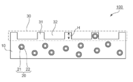
- FIG. 1 is a schematic cross-sectional view of a polarizer protective film according to one embodiment of the present invention.
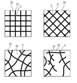
- FIG. 3 is a schematic plan view showing a representative example of a plan view shape of a convex portion on an uneven surface in a polarizer protective film according to an embodiment of the present invention.
- 1 is a schematic cross-sectional view of a polarizing plate according to an embodiment of the present invention.
- FIG. 1 is a schematic cross-sectional view of a polarizer protective film according to one embodiment of the present invention.
- the polarizer protective film 100 of the illustrated example is composed of a resin film containing a resin as the matrix 10 and the light diffusing fine particles 20 dispersed in the matrix 10. With such a structure, light diffusion performance is imparted to the polarizer protective film itself.
- the polarizer protective film can also serve as the light diffusion film, and the polarizer protective film becomes a part of the polarizing plate, so that the polarizing plate is provided with the light diffusion performance and is significantly thinned at the same time. can do.
- the refractive index n M of the matrix and the refractive index n P of the light diffusing fine particles preferably satisfy the following relationship:
- is more preferably 0.07 or more, still more preferably 0.10 or more.
- may be, for example, 0.20. With such a configuration, even better light diffusion performance can be realized.
- the resin and the light diffusing fine particles that constitute the matrix will be described later in Sections A-2 and A-3, respectively.
- the surface 30 of the polarizer protective film 100 has an uneven shape.
- the uneven surface 30 has a convex portion 31 and a concave portion (air portion or void portion) 32.
- the ratio B / A of the cross-sectional area B of the concave portion to the cross-sectional area A of the entire uneven surface is 50% or more, typically more than 50%, preferably 60% or more, more preferably 70% or more. Is.
- the upper limit of the ratio B / A may be 90%, for example. When the ratio B / A is in such a range, sufficient brightness can be exhibited, and a good diffusion performance is imparted to the polarizer protective film while maintaining a wide brightness viewing angle, and the polarizer protective film is provided.
- the adhesive strength between the polarizer protective film and the polarizer can be secured when is laminated on the polarizer.
- the cross-sectional area A of the entire uneven surface is the area of a portion surrounded by a line connecting the surfaces of the convex portions, a line connecting the bottoms of the concave portions, and vertical lines at both ends of the film (for reference,
- the cross-sectional area B of each recess is the cross-sectional area B of each recess 32 (the line connecting the wall of the adjacent protrusion to the surface of the protrusion and the bottom of the recess).
- the area enclosed by and) is the total.
- the ratio B / A can correspond to the porosity.
- the height H of the convex portion 31 on the uneven surface is preferably 3 ⁇ m or more, more preferably 5 ⁇ m or more, and further preferably 10 ⁇ m or more.
- the upper limit of the height H of the protrusion may be, for example, 15 ⁇ m.
- a substantially low-refractive-index portion defined by a recess air portion or void
- a substantially low-refractive-index portion defined by a recess air portion or void
- good light diffusing performance can be realized and the luminance viewing angle can be increased.
- a polarizer (polarizing plate) and a light diffusing film are separately placed, and as a result, an air layer is interposed between the polarizing plate and the light diffusing film. While the air layer hinders the reduction in thickness, the retroreflection of the air layer maintains a large luminance viewing angle. If the polarizing plate and the light diffusing film are integrated, it is possible to reduce the thickness and integrate the functions, but the elimination of the air layer reduces the luminance viewing angle.
- the polarizer protective film is provided with light diffusing performance, and by forming a point bond, the polarizing plate is provided with a desired light diffusing performance and a brightness viewing angle is increased. Can be maintained large (wide). Further, according to the embodiment of the present invention, since the polarizer protective film itself has a light diffusing property and also serves as a light diffusing film, a remarkable thinning is realized by a synergistic effect with the effect of eliminating the air layer. it can.
- the planar view shape of the convex portion 31 may be a regular shape (for example, a lattice shape) or an irregular shape as shown in FIG. 2, for example.
- the convex portion 31 preferably has an intersection C when seen in a plan view, as shown in FIG. 2. In other words, the convex portion extends in two or more directions.
- the pitch of the protrusions (the distance between the protrusions) is preferably 1000 ⁇ m or less, more preferably 500 ⁇ m or less, and further preferably 100 ⁇ m or less.
- a bias with an angle of 1 to 90 degrees may be provided.
- the pitch means an average pitch, and preferably has a distribution such that 50% or less is within ⁇ 50% of the average value of the pitch.
- the area ratio of the concave portion 32 to the entire area when the uneven surface is viewed in plan is preferably 50% or more, preferably 60% or more, and more preferably 70% or more.
- the upper limit of the area ratio of the recess may be 90%, for example.
- the convex portion 31 includes the light diffusing fine particles 20. With such a configuration, better diffusion performance is imparted, and even with a uniform uneven pattern, it is possible to reduce uneven optical interference with the pixels of the liquid crystal panel.
- the uneven surface can be formed by any appropriate method.
- the uneven shape can be formed by, for example, a surface roughening method or a method of giving unevenness by fine particles. Specific examples of the surface roughening method include embossing and sandblasting.
- the uneven surface (uneven shape) can be typically formed by shaping the surface of the melt-extruded film with an embossing roll.
- any suitable resin capable of forming a polarizer protective film can be adopted.
- a resin include (meth) acrylic resin, polyester resin (for example, polyethylene terephthalate (PET)), cycloolefin resin (for example, norbornene resin), cellulose resin (for example, triacetyl resin).
- PET polyethylene terephthalate
- cycloolefin resin for example, norbornene resin
- cellulose resin for example, triacetyl resin
- TAC cellulose
- polyvinyl alcohol-based resin polycarbonate-based resin, polyamide-based resin, polyimide-based resin, polyether sulfone-based resin, polysulfone-based resin, polystyrene-based resin, polyolefin-based resin, and acetate-based resin.
- (meth) acrylic resins may be used alone or in combination of two or more. From the viewpoint of optical properties, transparency and versatility, (meth) acrylic resins, polyester resins and cycloolefin resins are preferable, and (meth) acrylic resins are more preferable.
- (meth) acryl means acryl and / or methacryl.
- any appropriate (meth) acrylic resin can be adopted as the (meth) acrylic resin.
- the acrylic resin typically contains an alkyl (meth) acrylate as a main component as a monomer unit.
- the alkyl (meth) acrylate constituting the main skeleton of the acrylic resin include linear or branched alkyl groups having 1 to 18 carbon atoms. These can be used alone or in combination.
- any appropriate copolymerization monomer may be introduced into the acrylic resin by copolymerization. The type, number, copolymerization ratio, etc. of such copolymerized monomers can be appropriately set according to the purpose.
- the constituent components (monomer units) of the main skeleton of the acrylic resin will be described later with reference to the general formula (2).
- the acrylic resin may preferably have at least one selected from a glutarimide unit, a lactone ring unit, a maleic anhydride unit, a maleimide unit and a glutaric anhydride unit.
- the acrylic resin having a lactone ring unit is described in, for example, Japanese Patent Application Laid-Open No. 2008-181078, and the description of that publication is incorporated herein by reference.
- the glutarimide unit is preferably represented by the following general formula (1):
- R 1 and R 2 each independently represent hydrogen or an alkyl group having 1 to 8 carbon atoms
- R 3 is an alkyl group having 1 to 18 carbon atoms or 3 to 12 carbon atoms. Is a cycloalkyl group or an aryl group having 6 to 10 carbon atoms.
- R 1 and R 2 are each independently hydrogen or a methyl group
- R 3 is hydrogen, a methyl group, a butyl group or a cyclohexyl group. More preferably, R 1 is a methyl group, R 2 is hydrogen and R 3 is a methyl group.
- the alkyl (meth) acrylate is typically represented by the following general formula (2):
- R 4 represents a hydrogen atom or a methyl group
- R 5 represents a hydrogen atom or an optionally substituted aliphatic or alicyclic hydrocarbon group having 1 to 6 carbon atoms. Show.
- the substituent include halogen and hydroxyl group.
- Specific examples of the alkyl (meth) acrylate include methyl (meth) acrylate, ethyl (meth) acrylate, n-propyl (meth) acrylate, n-butyl (meth) acrylate, and t-methacrylate.
- R 5 is preferably a hydrogen atom or a methyl group.
- a particularly preferred alkyl (meth) acrylate is methyl acrylate or methyl methacrylate.
- the acrylic resin may include only a single glutarimide unit, or may include a plurality of glutarimide units having different R 1 , R 2 and R 3 in the general formula (1).
- the content ratio of the glutarimide unit in the acrylic resin is preferably 2 mol% to 50 mol%, more preferably 2 mol% to 45 mol%, further preferably 2 mol% to 40 mol%, particularly preferably 2 mol%. % To 35 mol%, most preferably 3 to 30 mol%.
- the content ratio is less than 2 mol%, the effects (for example, high optical properties, high mechanical strength, excellent adhesion with a polarizer, and thinning) derived from the glutarimide unit are sufficiently exhibited. May not be performed. If the content ratio exceeds 50 mol%, for example, heat resistance and transparency may be insufficient.
- the acrylic resin may include only a single alkyl (meth) acrylate unit, or may include a plurality of alkyl (meth) acrylate units having different R 4 and R 5 in the general formula (2). Good.
- the content ratio of the alkyl (meth) acrylate unit in the acrylic resin is preferably 50 mol% to 98 mol%, more preferably 55 mol% to 98 mol%, further preferably 60 mol% to 98 mol%, particularly preferably Is 65 mol% to 98 mol%, most preferably 70 mol% to 97 mol%.
- the content ratio is less than 50 mol%, the effects (for example, high heat resistance and high transparency) derived from the alkyl (meth) acrylate unit may not be sufficiently exhibited.
- the content ratio is more than 98 mol%, the resin becomes brittle and easily cracked, high mechanical strength cannot be sufficiently exhibited, and productivity may be deteriorated.
- the above acrylic resin may contain units other than the glutarimide unit and the alkyl (meth) acrylate unit.
- the acrylic resin can contain, for example, 0 wt% to 10 wt% of an unsaturated carboxylic acid unit that is not involved in the intramolecular imidization reaction described below.
- the content ratio of the unsaturated carboxylic acid unit is preferably 0% by weight to 5% by weight, more preferably 0% by weight to 1% by weight. When the content is within such a range, transparency, retention stability and moisture resistance can be maintained.
- the acrylic resin may contain a copolymerizable vinyl monomer unit (other vinyl monomer unit) other than the above.
- other vinyl-based monomers include acrylonitrile, methacrylonitrile, ethacrylonitrile, allyl glycidyl ether, maleic anhydride, itaconic anhydride, N-methylmaleimide, N-ethylmaleimide, N-cyclohexylmaleimide, acryl Aminoethyl acid, propylaminoethyl acrylate, dimethylaminoethyl methacrylate, ethylaminopropyl methacrylate, cyclohexylaminoethyl methacrylate, N-vinyldiethylamine, N-acetylvinylamine, allylamine, methallylamine, N-methylallylamine, 2 -Isopropenyl-oxazoline, 2-vinyl-oxazoline,
- styrene-based monomers such as styrene and ⁇ -methylstyrene.
- the content ratio of the other vinyl-based monomer unit is preferably 0 to 1% by weight, and more preferably 0 to 0.1% by weight. Within such a range, it is possible to suppress the development of undesired retardation and the decrease in transparency.
- the imidization ratio of the acrylic resin is preferably 2.5% to 20.0%.
- the imidization ratio is represented by the ratio of glutarimide units and alkyl (meth) acrylate units. This ratio can be obtained, for example, from the NMR spectrum or IR spectrum of the acrylic resin.
- the imidization ratio can be determined by 1 H-NMR measurement of the resin using 1 HNMR BRUKER AvanceIII (400 MHz).
- the peak area derived from the O—CH 3 proton of the alkyl (meth) acrylate in the vicinity of 3.5 ppm to 3.8 ppm is A
- the peak area of N-CH 3 in the glutarimide in the vicinity of 3.0 ppm to 3.3 ppm is B
- Imidization ratio Im (%) ⁇ B / (A + B) ⁇ ⁇ 100
- the above acrylic resin has a Tg (glass transition temperature) of preferably 110 ° C. or higher, more preferably 115 ° C. or higher, further preferably 120 ° C. or higher, particularly preferably 125 ° C. or higher, most preferably 130 ° C. or higher.
- Tg glass transition temperature
- the upper limit of Tg is preferably 300 ° C or lower, more preferably 290 ° C or lower, further preferably 285 ° C or lower, particularly preferably 200 ° C or lower, and most preferably 160 ° C or lower.
- Tg glass transition temperature
- the above acrylic resin can be manufactured, for example, by the following method.
- This method comprises: (I) an alkyl (meth) acrylate monomer corresponding to an alkyl (meth) acrylate unit represented by the general formula (2), an unsaturated carboxylic acid monomer and / or a precursor monovalent thereof.
- a copolymer (a) by copolymerizing the polymer with the polymer; and (II) treating the copolymer (a) with an imidizing agent to obtain a copolymer (a) in the copolymer (a).
- Light Diffusing Fine Particles As the light diffusing fine particles, any appropriate one can be used. Specific examples include inorganic fine particles and polymer fine particles.
- the light diffusing fine particles are preferably polymer fine particles.
- the material of the polymer particles include silicone resin, (meth) acrylic resin (eg, polymethylmethacrylate), polystyrene resin, polyurethane resin, and melamine resin. Since these resins have excellent dispersibility in the matrix and an appropriate difference in refractive index from the matrix, a polarizer protective film having excellent light diffusion performance can be obtained. Preferred are silicone resins and polymethylmethacrylate.
- the shape of the light diffusing fine particles may be, for example, a spherical shape, a flat shape, or an irregular shape.
- the light diffusing fine particles may be used alone or in combination of two or more kinds.
- the volume average particle diameter of the light diffusing fine particles is preferably 1 ⁇ m to 10 ⁇ m, more preferably 1.5 ⁇ m to 6 ⁇ m. By setting the volume average particle diameter in the above range, a polarizer protective film having excellent light diffusion performance can be obtained.
- the volume average particle diameter can be measured using, for example, an ultracentrifugal automatic particle size distribution measuring device.
- the refractive index of the light diffusing fine particles is preferably 1.30 to 1.70, more preferably 1.40 to 1.65.
- of the difference between the refractive index n P of the light diffusing fine particles and the refractive index n M of the matrix matrix is 0.05 or more as described above.
- the light diffusing fine particles may be, for example, core-shell fine particles having a core and a shell and different in refractive index between the core and the shell.
- GRIN (gradient index) fine particles may be used.
- Core shell fine particles and GRIN fine particles are described in, for example, JP-A-6-347617, JP-A-2003-262710, JP-A-2002-212245, JP-A-2002-214408, JP-A-2002-328207, and It is described in Japanese Patent Laid-Open No. 2010-077243 and Japanese Patent Laid-Open No. 2010-107616. The descriptions of these publications are incorporated herein by reference.
- the light-diffusing fine particles may have a refractive index modulation region 22 in which the refractive index changes substantially continuously outside the vicinity of the surface of the light-diffusing fine particles 21, as shown in FIG. 1, for example.
- the refractive index modulation region can be formed by, for example, introducing a specific ultrafine particle component into the matrix. With such a configuration, backscattering can be suppressed, and as a result, more excellent light diffusion performance can be realized. Details of the light diffusing fine particles in which the refractive index modulation region is formed are described in, for example, JP2012-88692A, JP2012-83741A, JP2012-83743A, and JP2012-83744A. It is described in. The descriptions in these publications are incorporated herein by reference.
- the content of the light diffusing fine particles in the polarizer protective film is preferably 0.3% by weight to 50% by weight, more preferably 1% by weight to 30% by weight, and further preferably 2.5% by weight to It is 20% by weight.
- a polarizer protective film having excellent light diffusing performance can be obtained.
- the polarizer protective film preferably has substantially optical isotropy.
- “having substantially optical isotropy” means that the in-plane retardation Re (550) is 0 nm to 10 nm.
- the in-plane retardation Re (550) is more preferably 0 nm to 5 nm, further preferably 0 nm to 3 nm, and particularly preferably 0 nm to 2 nm.
- Re (550) of the polarizer protective film is in such a range, it is possible to prevent adverse effects on display characteristics when a polarizing plate including the polarizer protective film is applied to an image display device.
- Re (550) is the in-plane retardation of the film measured with light having a wavelength of 550 nm at 23 ° C.
- nx is the refractive index in the direction in which the in-plane refractive index is maximum (that is, the slow axis direction)
- ny is the direction in the plane that is orthogonal to the slow axis (that is, the fast axis direction).
- the refractive index, and d is the film thickness (nm).
- the light transmittance is preferably 75% or more. It is more preferably 80% or more, still more preferably 85% or more. When the light transmittance is in such a range, desired optical characteristics can be secured.
- the light transmittance can be measured, for example, by a method according to ASTM-D-1003.
- the haze of the polarizer protective film is preferably 50% to 99%, more preferably 70% to 95%.
- the polarizer protective film preferably has the following characteristics.
- the difference between the light transmittances at 450 nm and 650 nm and the light transmittance at 550 nm is preferably within ⁇ 5%, more preferably within ⁇ 2%. is there.
- the brightness half-value angle (the angle at which the brightness is 50% of the front surface) is preferably 56 ° (28 ° on one side) or more, and more preferably 60 ° to 70 ° (30 on one side). ° to 35 °). Furthermore, the angle at which the luminance is 25% of the front is preferably 90 ° (45 ° on one side) or more, and more preferably 96 ° to 120 ° (48 ° to 60 ° on one side). According to the embodiments of the present invention, it is possible to impart excellent diffusion performance to the polarizer protective film and maintain a wide luminance viewing angle.
- the refractive index n F of the entire polarizer protective film is preferably 1.3 to 1.8, more preferably 1.4 to 1.6.
- the difference in refractive index between the low refractive index portion of the polarizing plate and the low refractive index portion defined by the point adhesion to the polarizer can be set within a desired range.
- the water vapor transmission rate of the polarizer protective film is preferably 300 g / m 2 ⁇ 24 hr or less, more preferably 250 g / m 2 ⁇ 24 hr or less, further preferably 200 g / m 2 ⁇ 24 hr or less, particularly preferably 150 g / m 2 ⁇ 24 hr.
- the following is most preferably 100 g / m 2 ⁇ 24 hr or less.
- FIG. 3 is a schematic sectional view of a polarizing plate according to an embodiment of the present invention.
- the polarizing plate 200 in the illustrated example includes a polarizer 130, and the polarizer protective film 100 described in the section A, which is laminated on the polarizer 130 via an adhesive layer 120.
- the polarizer protective film 100 is arranged such that the surface having the above-mentioned concavo-convex shape is on the side of the polarizer 130.
- the adhesive layer is composed of any suitable adhesive or pressure sensitive adhesive.
- the adhesive layer is typically formed of a water-based adhesive (for example, a vinyl alcohol-based adhesive) or an active energy ray-curable adhesive.
- the pressure-sensitive adhesive layer is typically formed of an acrylic pressure-sensitive adhesive.
- another protective film 140 is arranged on the opposite side of the polarizer from the protective film 100.
- the pressure-sensitive adhesive layer 150 is further provided as the outermost layer so that the polarizing plate can be attached to the image display cell.
- a separator (not shown) is detachably and temporarily attached to the surface of the pressure-sensitive adhesive layer 150 to protect the pressure-sensitive adhesive layer until the polarizing plate is actually used and to enable roll formation.
- the polarizing plate according to the embodiment of the present invention can be typically used as a back side polarizing plate of an image display device.
- the concave portions 32 on the uneven surface of the polarizer protective film are formed (by the above point adhesion).
- a substantial low refractive index portion 110 is defined.
- the refractive index n L of the low refractive index portion is preferably more than 1.0 and 1.3 or less, and more preferably more than 1.0 and 1.2 or less.
- the difference (n F ⁇ n L ) between the refractive index n L of the low refractive index portion and the refractive index n F of the polarizer protective film is preferably 0.2 or more, more preferably 0.25 or more.
- the upper limit of the difference (n F ⁇ n L ) may be 0.4, for example.
- the ratio T / H of the thickness T of the adhesive layer 120 and the height H of the convex portion in the uneven shape is preferably 50% or less, more preferably 30% or less.
- the lower limit of the ratio T / H can be, for example, 10%.
- the resin film forming the polarizer may be a single-layer resin film or a laminate of two or more layers.
- the polarizer composed of a single layer resin film include hydrophilic polymer films such as polyvinyl alcohol (PVA) film, partially formalized PVA film, and ethylene / vinyl acetate copolymer partially saponified film.
- hydrophilic polymer films such as polyvinyl alcohol (PVA) film, partially formalized PVA film, and ethylene / vinyl acetate copolymer partially saponified film.
- examples thereof include polyene oriented films such as those subjected to dyeing treatment and stretching treatment with a dichroic substance such as iodine or dichroic dye, dehydrated PVA products and dehydrochlorinated polyvinyl chloride products.
- a polarizer obtained by dyeing a PVA-based film with iodine and uniaxially stretching it is used because it has excellent optical properties.
- the above dyeing with iodine is performed, for example, by immersing the PVA film in an aqueous iodine solution.
- the stretching ratio of the uniaxial stretching is preferably 3 to 7 times. Stretching may be performed after the dyeing treatment or may be performed while dyeing. Further, it may be stretched and then dyed.
- the PVA film is subjected to swelling treatment, crosslinking treatment, washing treatment, drying treatment and the like. For example, by immersing a PVA-based film in water and washing it before dyeing, not only can the stains on the surface of the PVA-based film and the antiblocking agent be washed, but also the PVA-based film can be swollen to prevent uneven dyeing. Can be prevented.
- the polarizer obtained using the laminate include a laminate of a resin base material and a PVA-based resin layer (PVA-based resin film) laminated on the resin base material, or a resin base material and the resin.
- a polarizer obtained by using a laminate with a PVA-based resin layer formed by coating on a base material examples include a polarizer obtained by using a laminate with a PVA-based resin layer formed by coating on a base material.
- a polarizer obtained by using a laminate of a resin base material and a PVA-based resin layer formed by coating on the resin base material is, for example, a resin base material obtained by applying a PVA-based resin solution to the resin base material and drying the solution.
- a PVA-based resin layer is formed thereon to obtain a laminate of a resin substrate and a PVA-based resin layer; the laminate is stretched and dyed to form the PVA-based resin layer as a polarizer obtain.
- the stretching typically includes dipping the laminate in a boric acid aqueous solution and stretching. Further, the stretching may further include optionally stretching the laminate at high temperature (for example, 95 ° C. or higher) in the air before stretching in the boric acid aqueous solution.
- the resin base material / polarizer laminate thus obtained may be used as it is (that is, the resin base material may be used as a protective layer of the polarizer), and the resin base material is peeled from the resin base material / polarizer laminate.
- any appropriate protective layer may be laminated and used on the peeled surface depending on the purpose. Details of the method for manufacturing such a polarizer are described in, for example, Japanese Patent Application Laid-Open No. 2012-73580. The entire description of the publication is incorporated herein by reference.
- the thickness of the polarizer is, for example, 1 ⁇ m to 80 ⁇ m. In one embodiment, the thickness of the polarizer is preferably 1 ⁇ m to 20 ⁇ m, more preferably 3 ⁇ m to 15 ⁇ m.
- the polarizing plate described in the above section B can be applied to an image display device. Therefore, the present invention also includes an image display device using such a polarizing plate.
- the image display device typically includes the polarizing plate described in the above item B on the back side.
- the polarizing plate is typically arranged so that the polarizer protective film described in the item A is on the back side.
- Typical examples of the image display device include a liquid crystal display device and an organic electroluminescence (EL) display device. Since the image display device has a configuration well known in the industry, detailed description thereof will be omitted.
- Luminance Viewing Angle SJ8000 manufactured by LG was disassembled, the liquid crystal panel with a polarizing plate was taken out, and the polarizing plate obtained in each of Examples and Comparative Examples was mounted as a backlight side polarizing plate.
- the light diffusion film provided in the backlight unit of the product was cut out and reassembled only at the mounting location.
- the luminance of the mounted product thus obtained was measured using Ezconstrast manufactured by ELDIM. When the luminance in the front direction was 100%, the angle at which the luminance was 25% was measured on both sides of the diffusion, and the sum of the angles on both sides was taken as the luminance viewing angle.
- the measured luminance viewing angle was expressed as a ratio (%) when the luminance viewing angle when the polarizing plate and the light diffusion film were separately placed was 100.
- Example 1> (Preparation of polarizer protective film) 9 parts of silicone resin fine particles (volume average particle diameter 4.5 ⁇ m) as light diffusing fine particles are charged into 100 parts of methacrylic resin (manufactured by Kuraray Co., Ltd., product name “Parapet HR-S”) in a single-screw extruder. Then, while being melt extruded at 260 ° C., an uneven shape was formed on one surface by an embossing roll to obtain a film having a thickness of 50 ⁇ m. The sectional area ratio of the concave portions was 70%, and the height of the convex portions was 10 ⁇ m.
- Corona treatment (treatment condition: 55 W ⁇ min / m 2 ) was applied to one surface of the resin base material, and 90 parts by weight of polyvinyl alcohol (polymerization degree: 4200, saponification degree: 99.2 mol%) and aceto 10 parts by weight of acetyl-modified PVA (polymerization degree 1200, acetoacetyl modification degree of about 5%, saponification degree of 99.0 mol% or more, trade name "Gosephimmer Z200" manufactured by Nippon Synthetic Chemical Industry Co., Ltd.), and potassium iodide An aqueous solution containing 13 parts by weight was applied at room temperature and dried in an environment of 60 ° C.
- a laminate having a thickness of 13 ⁇ m, and a laminate was prepared.
- the obtained laminate was uniaxially stretched 2.4 times in the longitudinal direction (longitudinal direction) between rolls having different peripheral speeds in an oven at 140 ° C (in-air auxiliary stretching).
- the laminated body was immersed in an insolubilizing bath having a liquid temperature of 30 ° C. (boric acid aqueous solution obtained by mixing 4 parts by weight of boric acid with 100 parts by weight of water) for 30 seconds (insolubilization treatment). Then, it is immersed for 60 seconds in a dyeing bath having a liquid temperature of 30 ° C.
- the laminated body was immersed in a cleaning bath having a liquid temperature of 30 ° C. (an aqueous solution obtained by mixing 4 parts by weight of potassium iodide with 100 parts by weight of water) (cleaning treatment). In this way, a polarizer having a thickness of 5 ⁇ m was formed on the resin base material.
- the uneven surface of the polarizer protective film was bonded to the polarizer surface of the resin base material / polarizer laminate obtained above through a polyvinyl alcohol adhesive (thickness 2 ⁇ m) by point adhesion. It was Next, the resin substrate was peeled off, and a methacrylic resin film (thickness 40 ⁇ m) was attached to the peeled surface via a polyvinyl alcohol adhesive.
- the methacrylic resin film was prepared by introducing a methacrylic resin (Kuraray Co., Ltd., product name "Parapet HR-S”) into a single-screw extruder and melt-extruding at 260 ° C. In this way, a polarizing plate was obtained.
- the refractive index of the low refractive index portion substantially defined in the polarizing plate was 1.15.
- the obtained polarizing plate was subjected to the evaluations of (2) and (3) above. The results are shown in Table 1.
- Example 2 A polarizer protective film was produced in the same manner as in Example 1 except that the embossing roll was changed, and the cross-sectional area ratio of the recesses was 55%.
- a polarizing plate was produced in the same manner as in Example 1 except that this polarizer protective film was used.
- the refractive index of the low refractive index portion substantially defined in the polarizing plate was 1.22.
- the obtained polarizing plate was subjected to the same evaluations as in Example 1. The results are shown in Table 1.
- Example 1 In the same manner as in Example 1 except that the embossing roll was changed, a polarizer protective film in which the sectional area ratio of the recesses was 30% was produced. A polarizing plate was produced in the same manner as in Example 1 except that this polarizer protective film was used. The refractive index of the low refractive index portion substantially defined in the polarizing plate was 1.34. The obtained polarizing plate was subjected to the same evaluations as in Example 1. The results are shown in Table 1.
- the polarizer protective film of the present invention is suitable for use as a polarizing plate.
- the polarizing plate of the present invention is suitably used for an image display device.
- the image display device of the present invention is a mobile device such as a personal digital assistant (PDA), a smartphone, a mobile phone, a watch, a digital camera, and a portable game machine; , Household electric appliances such as microwave ovens; back monitors, monitors for car navigation systems, car audio systems, etc .; display devices such as digital signage, information monitors for commercial stores; security devices such as monitoring monitors; It can be used for various applications such as nursing / medical devices such as medical monitors and medical monitors.
- PDA personal digital assistant
Landscapes
- Physics & Mathematics (AREA)
- General Physics & Mathematics (AREA)
- Optics & Photonics (AREA)
- Chemical & Material Sciences (AREA)
- Nonlinear Science (AREA)
- Dispersion Chemistry (AREA)
- Mathematical Physics (AREA)
- Crystallography & Structural Chemistry (AREA)
- Polarising Elements (AREA)
- Electroluminescent Light Sources (AREA)
- Devices For Indicating Variable Information By Combining Individual Elements (AREA)
Abstract
輝度視野角を狭めることなく光拡散機能が付与された偏光子保護フィルムを提供する。 本発明の偏光子保護フィルムは、マトリックスとしての樹脂とマトリックスに分散された光拡散性微粒子とを含む樹脂フィルムで構成され、表面が凹凸形状を有し、凹凸部分における全体の断面積Aに対する凹部の断面積Bの比率B/Aが50%以上である。
Description
本発明は、偏光子保護フィルム、偏光板および画像表示装置に関する。
近年、画像表示装置(例えば、液晶表示装置、有機EL表示装置)の薄型化およびデザイン性の向上(例えば、狭ベゼル化)に対する要望が非常に強まっている。これに伴い、画像表示装置に用いられる光学部材および/または光学フィルムの一体化および/または機能の統合に対する要望も強まっている。そのような一体化または機能の統合の一例として、偏光子に光拡散フィルムを直接貼り合わせて偏光板に光拡散機能を付与することが提案されている。しかし、提案された技術は、輝度視野角が小さくなるという問題がある。
本発明は上記従来の課題を解決するためになされたものであり、その主たる目的は、輝度視野角を狭めることなく光拡散機能が付与された偏光子保護フィルムを提供することにある。
本発明の偏光子保護フィルムは、マトリックスとしての樹脂と該マトリックスに分散された光拡散性微粒子とを含む樹脂フィルムで構成され、表面が凹凸形状を有し、凹凸部分における全体の断面積Aに対する凹部の断面積Bの比率B/Aが50%以上である。
1つの実施形態においては、上記マトリックスの屈折率nMと上記光拡散性微粒子の屈折率nPとは、以下の関係を満足する:
|nP-nM|≧0.05。
1つの実施形態においては、上記凹凸形状における凸部の高さHは3μm以上である。
1つの実施形態においては、上記偏光子保護フィルムは、上記凹凸形状における凸部に上記光拡散性微粒子を含む。
1つの実施形態においては、上記偏光子保護フィルムは、平面視したときに上記凹凸形状における凸部が交差点を有する。
1つの実施形態においては、上記偏光子保護フィルムは、平面視したときの全体面積に対する上記凹部の面積比率が50%以上である。
本発明の別の局面によれば、偏光板が提供される。この偏光板は、偏光子と、該偏光子に接着層を介して積層された上記の偏光子保護フィルムと、を有する。該偏光子保護フィルムは、上記凹凸形状を有する表面が該偏光子側となるよう配置されている。
1つの実施形態においては、上記偏光子と上記偏光子保護フィルムとの界面に、上記凹凸形状の凹部による実質的な低屈折率部が規定されている。1つの実施形態においては、上記低屈折率部の屈折率nLと上記偏光子保護フィルムの屈折率nFとの差(nF-nL)は0.2以上である。
1つの実施形態においては、上記接着層の厚みTと上記凹凸形状における凸部の高さHとの比T/Hは50%以下である。
本発明のさらに別の局面によれば、画像表示装置が提供される。この画像表示装置は、上記の偏光板を背面側に備える。
1つの実施形態においては、上記マトリックスの屈折率nMと上記光拡散性微粒子の屈折率nPとは、以下の関係を満足する:
|nP-nM|≧0.05。
1つの実施形態においては、上記凹凸形状における凸部の高さHは3μm以上である。
1つの実施形態においては、上記偏光子保護フィルムは、上記凹凸形状における凸部に上記光拡散性微粒子を含む。
1つの実施形態においては、上記偏光子保護フィルムは、平面視したときに上記凹凸形状における凸部が交差点を有する。
1つの実施形態においては、上記偏光子保護フィルムは、平面視したときの全体面積に対する上記凹部の面積比率が50%以上である。
本発明の別の局面によれば、偏光板が提供される。この偏光板は、偏光子と、該偏光子に接着層を介して積層された上記の偏光子保護フィルムと、を有する。該偏光子保護フィルムは、上記凹凸形状を有する表面が該偏光子側となるよう配置されている。
1つの実施形態においては、上記偏光子と上記偏光子保護フィルムとの界面に、上記凹凸形状の凹部による実質的な低屈折率部が規定されている。1つの実施形態においては、上記低屈折率部の屈折率nLと上記偏光子保護フィルムの屈折率nFとの差(nF-nL)は0.2以上である。
1つの実施形態においては、上記接着層の厚みTと上記凹凸形状における凸部の高さHとの比T/Hは50%以下である。
本発明のさらに別の局面によれば、画像表示装置が提供される。この画像表示装置は、上記の偏光板を背面側に備える。
本発明によれば、偏光子保護フィルムに光拡散性微粒子を分散させ、かつ、その少なくとも一方の表面に凹凸形状を形成し、さらに、当該凹凸形状における凹部の断面積比を所定値以上とすることにより、輝度視野角を狭めることなく光拡散機能が付与された偏光子保護フィルムを実現することができる。
以下、図面を参照して本発明の実施形態について説明するが、本発明はこれらの実施形態に限定されない。なお、図面は見やすくするために模式的に表されており、縦、横および厚みの比率、凹凸の形状および精細さ等が実際とは異なっている。
A.偏光子保護フィルム
A-1.全体構成
図1は、本発明の1つの実施形態による偏光子保護フィルムの概略断面図である。図示例の偏光子保護フィルム100は、マトリックス10としての樹脂とマトリックス10に分散された光拡散性微粒子20とを含む樹脂フィルムで構成される。このような構成であれば、偏光子保護フィルム自体に光拡散性能が付与される。その結果、偏光子保護フィルムが光拡散フィルムを兼ねることができ、かつ、偏光子保護フィルムは偏光板の一部となるので、偏光板への光拡散性能の付与および顕著な薄型化を同時に実現することができる。マトリックスの屈折率nMと光拡散性微粒子の屈折率nPとは、好ましくは以下の関係を満足する:
|nP-nM|≧0.05。
|nP-nM|は、より好ましくは0.07以上であり、さらに好ましくは0.10以上である。|nP-nM|の上限は、例えば0.20であり得る。このような構成であれば、さらに良好な光拡散性能が実現され得る。なお、マトリックスを構成する樹脂および光拡散性微粒子については、それぞれ、A-2項およびA-3項で後述する。
A-1.全体構成
図1は、本発明の1つの実施形態による偏光子保護フィルムの概略断面図である。図示例の偏光子保護フィルム100は、マトリックス10としての樹脂とマトリックス10に分散された光拡散性微粒子20とを含む樹脂フィルムで構成される。このような構成であれば、偏光子保護フィルム自体に光拡散性能が付与される。その結果、偏光子保護フィルムが光拡散フィルムを兼ねることができ、かつ、偏光子保護フィルムは偏光板の一部となるので、偏光板への光拡散性能の付与および顕著な薄型化を同時に実現することができる。マトリックスの屈折率nMと光拡散性微粒子の屈折率nPとは、好ましくは以下の関係を満足する:
|nP-nM|≧0.05。
|nP-nM|は、より好ましくは0.07以上であり、さらに好ましくは0.10以上である。|nP-nM|の上限は、例えば0.20であり得る。このような構成であれば、さらに良好な光拡散性能が実現され得る。なお、マトリックスを構成する樹脂および光拡散性微粒子については、それぞれ、A-2項およびA-3項で後述する。
本発明の実施形態においては、偏光子保護フィルム100の表面30は凹凸形状を有する。凹凸表面30は、凸部31と凹部(空気部または空隙部)32とを有する。凹凸表面全体の断面積Aに対する凹部の断面積Bの比率B/Aは50%以上であり、代表的には50%を超えており、好ましくは60%以上であり、より好ましくは70%以上である。比率B/Aの上限は、例えば90%であり得る。比率B/Aがこのような範囲であれば、十分な輝度を発現させることができ、輝度視野角を広く維持しつつ偏光子保護フィルムに良好な拡散性能が付与されるとともに、偏光子保護フィルムが偏光子に積層される際に偏光子保護フィルムと偏光子との接着強度が確保され得る。なお、凹凸表面全体の断面積Aは、凸部の表面を結ぶ線と凹部の底を結ぶ線とフィルム両端の上下方向の線とで囲まれた部分の面積であり(参考として、当該部分の外側を破線で囲って図1に示す)、凹部の断面積Bは、それぞれの凹部32の断面積(隣接する凸部の壁の線と凸部の表面を結ぶ線と凹部の底を結ぶ線とで囲まれた部分の面積)の合計である。比率B/Aは空隙率に対応し得る。
凹凸表面における凸部31の高さHは、好ましくは3μm以上であり、より好ましくは5μm以上であり、さらに好ましくは10μm以上である。凸部の高さHの上限は、例えば15μmであり得る。凸部の高さがこのような範囲であれば、偏光子保護フィルムが偏光子に積層される際に、偏光子保護フィルムの凸部(実質的には、凸部の上部)のみが偏光子に接着され得る。なお、本明細書において、凸部のみの接着を便宜上「点接着」と称する場合がある。このような点接着により、点接着部分近傍に凹部(空気部または空隙部)による実質的な低屈折率部が規定される。その結果、良好な光拡散性能を実現するとともに輝度視野角を大きくすることができる。従来、画像表示装置において偏光子(偏光板)と光拡散フィルムとは別置きされ、その結果、偏光板と光拡散フィルムとの間には空気層が介在している。当該空気層は薄型化の障害となる一方で、当該空気層による再帰反射により輝度視野角が大きく維持される。偏光板と光拡散フィルムとを一体化すると薄型化および機能の統合は実現できるが、上記空気層の排除により輝度視野角が小さくなる。点接着部分近傍に低屈折率部を形成することにより、空気層が存在する場合と同様に光が効率的に再帰反射される。したがって、本発明の実施形態によれば、偏光子保護フィルムに光拡散性能を付与し、かつ、点接着を形成することにより、偏光板に所望の光拡散性能を付与するとともに、輝度視野角を大きく(広く)維持することができる。さらに、本発明の実施形態によれば、偏光子保護フィルム自体が光拡散性能を有し光拡散フィルムを兼ねるので、空気層の排除の効果との相乗的な効果により、顕著な薄型化が実現できる。
凹凸表面における凸部31の平面視形状は、任意の適切な形状が採用され得る。凸部の平面視形状は、例えば図2に示すように、規則性を有する形状(例えば、格子状)であってもよく、不規則形状であってもよい。凸部31は、好ましくは図2に示すように、平面視したときに交差点Cを有する。言い換えれば、凸部は、2方向以上の方向に延びる。凸部のピッチ(凸部と凸部との間隔)は、好ましくは1000μm以下であり、より好ましくは500μm以下であり、さらに好ましくは100μm以下である。凸部の平面視形状が規則性を有する場合、角度を1度~90度のバイアスを設けてもよい。凸部の平面視形状が不規則形状である場合、ピッチは平均ピッチを意味し、ピッチの平均値に対し±50%以内が5割以上となるような分布であることが好ましい。このような構成であれば、偏光子保護フィルムが偏光子に積層される際に偏光子保護フィルムと偏光子との接着強度が確保され、かつ、良好な表示品位が確保され得る。
凹凸表面を平面視したときの全体面積に対する凹部32の面積比率は、好ましくは50%以上であり、好ましくは60%以上であり、より好ましくは70%以上である。凹部の面積比率の上限は、例えば90%であり得る。凹部の面積比率がこのような範囲であれば、輝度視野角を広く維持しつつ偏光子保護フィルムに良好な拡散性能が付与されるとともに、偏光子保護フィルムが偏光子に積層される際に偏光子保護フィルムと偏光子との接着強度が確保され得る。
1つの実施形態においては、図1に示すように、凸部31に光拡散性微粒子20が含まれている。このような構成であれば、より良好な拡散性能が付与され、均一な凹凸パターンであっても、液晶パネルの画素などとの光学干渉ムラを低減することが可能である。
凹凸表面(凹凸形状)は、任意の適切な方法により形成され得る。凹凸形状は、例えば、粗面化方式、微粒子により凹凸を付与する方式により形成され得る。粗面化方式の具体例としては、エンボス加工、サンドブラストが挙げられる。凹凸表面(凹凸形状)は、代表的には、溶融押出したフィルムの表面をエンボスロールで賦形することにより形成され得る。
A-2.マトリックス
マトリックスを構成する樹脂としては、偏光子保護フィルムを形成し得る任意の適切な樹脂が採用され得る。このような樹脂の具体例としては、(メタ)アクリル系樹脂、ポリエステル系樹脂(例えば、ポリエチレンテレフタレート(PET))、シクロオレフィン系樹脂(例えば、ノルボルネン系樹脂)、セルロース系樹脂(例えば、トリアセチルセルロース(TAC))、ポリビニルアルコール系樹脂、ポリカーボネート系樹脂、ポリアミド系樹脂、ポリイミド系樹脂、ポリエーテルスルホン系樹脂、ポリスルホン系樹脂、ポリスチレン系樹脂、ポリオレフィン系樹脂、アセテート系樹脂が挙げられる。これらの樹脂は、単独で用いてもよく2種以上を併用してもよい。光学特性、透明性および汎用性の観点から、(メタ)アクリル系樹脂、ポリエステル系樹脂、シクロオレフィン系樹脂が好ましく、(メタ)アクリル系樹脂がさらに好ましい。なお、本明細書において「(メタ)アクリル」とは、アクリルおよび/またはメタクリルを意味する。
マトリックスを構成する樹脂としては、偏光子保護フィルムを形成し得る任意の適切な樹脂が採用され得る。このような樹脂の具体例としては、(メタ)アクリル系樹脂、ポリエステル系樹脂(例えば、ポリエチレンテレフタレート(PET))、シクロオレフィン系樹脂(例えば、ノルボルネン系樹脂)、セルロース系樹脂(例えば、トリアセチルセルロース(TAC))、ポリビニルアルコール系樹脂、ポリカーボネート系樹脂、ポリアミド系樹脂、ポリイミド系樹脂、ポリエーテルスルホン系樹脂、ポリスルホン系樹脂、ポリスチレン系樹脂、ポリオレフィン系樹脂、アセテート系樹脂が挙げられる。これらの樹脂は、単独で用いてもよく2種以上を併用してもよい。光学特性、透明性および汎用性の観点から、(メタ)アクリル系樹脂、ポリエステル系樹脂、シクロオレフィン系樹脂が好ましく、(メタ)アクリル系樹脂がさらに好ましい。なお、本明細書において「(メタ)アクリル」とは、アクリルおよび/またはメタクリルを意味する。
(メタ)アクリル系樹脂としては、任意の適切な(メタ)アクリル系樹脂が採用され得る。なお、記載の簡略化のため、以下、(メタ)アクリル系樹脂を単にアクリル系樹脂と称する。アクリル系樹脂は、代表的には、モノマー単位として、アルキル(メタ)アクリレートを主成分として含有する。アクリル系樹脂の主骨格を構成するアルキル(メタ)アクリレートとしては、直鎖状または分岐鎖状のアルキル基の炭素数1~18のものを例示できる。これらは単独であるいは組み合わせて使用することができる。さらに、アクリル系樹脂には、任意の適切な共重合モノマーを共重合により導入してもよい。このような共重合モノマーの種類、数、共重合比等は目的に応じて適切に設定され得る。アクリル系樹脂の主骨格の構成成分(モノマー単位)については、一般式(2)を参照しながら後述する。
アクリル系樹脂は、好ましくは、グルタルイミド単位、ラクトン環単位、無水マレイン酸単位、マレイミド単位および無水グルタル酸単位から選択される少なくとも1つを有していてもよい。ラクトン環単位を有するアクリル系樹脂は、例えば特開2008-181078号公報に記載されており、当該公報の記載は本明細書に参考として援用される。グルタルイミド単位は、好ましくは、下記一般式(1)で表される:

一般式(1)において、R1およびR2は、それぞれ独立して、水素または炭素数1~8のアルキル基を示し、R3は、炭素数1~18のアルキル基、炭素数3~12のシクロアルキル基、または炭素数6~10のアリール基を示す。一般式(1)において、好ましくは、R1およびR2は、それぞれ独立して水素またはメチル基であり、R3は水素、メチル基、ブチル基またはシクロヘキシル基である。より好ましくは、R1はメチル基であり、R2は水素であり、R3はメチル基である。
上記アルキル(メタ)アクリレートは、代表的には、下記一般式(2)で表される:
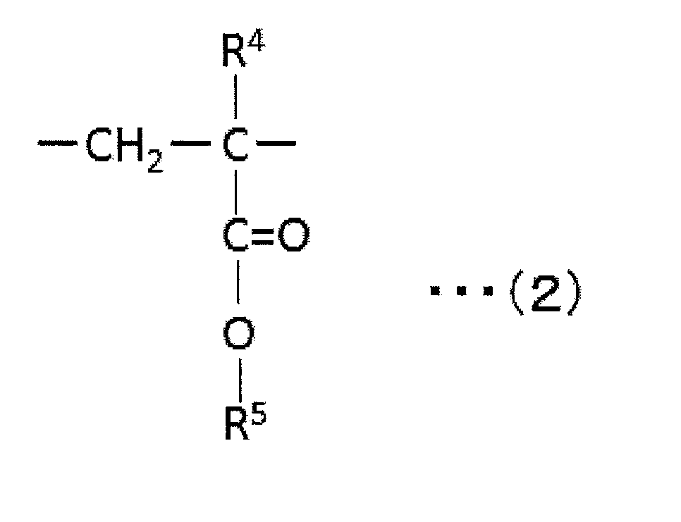
一般式(2)において、R4は、水素原子またはメチル基を示し、R5は、水素原子、あるいは、置換されていてもよい炭素数1~6の脂肪族または脂環式炭化水素基を示す。置換基としては、例えば、ハロゲン、水酸基が挙げられる。アルキル(メタ)アクリレートの具体例としては、(メタ)アクリル酸メチル、(メタ)アクリル酸エチル、(メタ)アクリル酸n-プロピル、(メタ)アクリル酸n-ブチル、(メタ)アクリル酸t-ブチル、(メタ)アクリル酸n-ヘキシル、(メタ)アクリル酸シクロヘキシル、(メタ)アクリル酸クロロメチル、(メタ)アクリル酸2-クロロエチル、(メタ)アクリル酸2-ヒドロキシエチル、(メタ)アクリル酸3-ヒドロキシプロピル、(メタ)アクリル酸2,3,4,5,6-ペンタヒドロキシヘキシルおよび(メタ)アクリル酸2,3,4,5-テトラヒドロキシペンチルが挙げられる。一般式(2)において、R5は、好ましくは、水素原子またはメチル基である。したがって、特に好ましいアルキル(メタ)アクリレートは、アクリル酸メチルまたはメタクリル酸メチルである。
上記アクリル系樹脂は、単一のグルタルイミド単位のみを含んでいてもよいし、上記一般式(1)におけるR1、R2およびR3が異なる複数のグルタルイミド単位を含んでいてもよい。
上記アクリル系樹脂におけるグルタルイミド単位の含有割合は、好ましくは2モル%~50モル%、より好ましくは2モル%~45モル%、さらに好ましくは2モル%~40モル%、特に好ましくは2モル%~35モル%、最も好ましくは3モル%~30モル%である。含有割合が2モル%より少ないと、グルタルイミド単位に由来して発現される効果(例えば、高い光学的特性、高い機械的強度、偏光子との優れた接着性、薄型化)が十分に発揮されないおそれがある。含有割合が50モル%を超えると、例えば、耐熱性、透明性が不十分となるおそれがある。
上記アクリル系樹脂は、単一のアルキル(メタ)アクリレート単位のみを含んでいてもよいし、上記一般式(2)におけるR4およびR5が異なる複数のアルキル(メタ)アクリレート単位を含んでいてもよい。
上記アクリル系樹脂におけるアルキル(メタ)アクリレート単位の含有割合は、好ましくは50モル%~98モル%、より好ましくは55モル%~98モル%、さらに好ましくは60モル%~98モル%、特に好ましくは65モル%~98モル%、最も好ましくは70モル%~97モル%である。含有割合が50モル%より少ないと、アルキル(メタ)アクリレート単位に由来して発現される効果(例えば、高い耐熱性、高い透明性)が十分に発揮されないおそれがある。上記含有割合が98モル%よりも多いと、樹脂が脆くて割れやすくなり、高い機械的強度が十分に発揮できず、生産性に劣るおそれがある。
上記アクリル系樹脂は、グルタルイミド単位およびアルキル(メタ)アクリレート単位以外の単位を含んでいてもよい。
1つの実施形態においては、アクリル系樹脂は、後述する分子内イミド化反応に関与していない不飽和カルボン酸単位を例えば0重量%~10重量%含有することができる。不飽和カルボン酸単位の含有割合は、好ましくは0重量%~5重量%であり、より好ましくは0重量%~1重量%である。含有量がこのような範囲であれば、透明性、滞留安定性および耐湿性を維持することができる。
1つの実施形態においては、アクリル系樹脂は、上記以外の共重合可能なビニル系単量体単位(他のビニル系単量体単位)を含有することができる。その他のビニル系単量体としては、例えば、アクリロニトリル、メタクリロニトリル、エタクリロニトリル、アリルグリシジルエーテル、無水マレイン酸、無水イタコン酸、N-メチルマレイミド、N-エチルマレイミド、N-シクロヘキシルマレイミド、アクリル酸アミノエチル、アクリル酸プロピルアミノエチル、メタクリル酸ジメチルアミノエチル、メタクリル酸エチルアミノプロピル、メタクリル酸シクロヘキシルアミノエチル、N-ビニルジエチルアミン、N-アセチルビニルアミン、アリルアミン、メタアリルアミン、N-メチルアリルアミン、2-イソプロペニル-オキサゾリン、2-ビニル-オキサゾリン、2-アクロイル-オキサゾリン、N-フェニルマレイミド、メタクリル酸フェニルアミノエチル、スチレン、α-メチルスチレン、p-グリシジルスチレン、p-アミノスチレン、2-スチリル-オキサゾリンなどがあげられる。これらは、単独で用いてもよく併用してもよい。好ましくは、スチレン、α-メチルスチレンなどのスチレン系単量体である。他のビニル系単量体単位の含有割合は、好ましくは0~1重量%であり、より好ましくは0~0.1重量%である。このような範囲であれば、所望でない位相差の発現および透明性の低下を抑制することができる。
上記アクリル系樹脂におけるイミド化率は、好ましくは2.5%~20.0%である。イミド化率がこのような範囲であれば、耐熱性、透明性および成形加工性に優れた樹脂が得られ、フィルム成形時のコゲの発生や機械的強度の低下が防止され得る。上記アクリル系樹脂において、イミド化率は、グルタルイミド単位とアルキル(メタ)アクリレート単位との比で表される。この比は、例えば、アクリル系樹脂のNMRスペクトル、IRスペクトル等から得ることができる。本実施形態においては、イミド化率は、1HNMR BRUKER AvanceIII(400MHz)を用いて、樹脂の1H-NMR測定により求めることができる。より具体的には、3.5ppmから3.8ppm付近のアルキル(メタ)アクリレートのO-CH3プロトン由来のピーク面積をAとし、3.0ppmから3.3ppm付近のグルタルイミドのN-CH3プロトン由来のピークの面積をBとして、次式により求められる。
イミド化率Im(%)={B/(A+B)}×100
イミド化率Im(%)={B/(A+B)}×100
上記アクリル系樹脂は、Tg(ガラス転移温度)が、好ましくは110℃以上、より好ましくは115℃以上、さらに好ましくは120℃以上、特に好ましくは125℃以上、最も好ましくは130℃以上である。Tgが110℃以上であれば、このような樹脂から得られた偏光子保護フィルムを含む偏光板は、耐久性に優れたものとなりやすい。Tgの上限値は、好ましくは300℃以下、より好ましくは290℃以下、さらに好ましくは285℃以下、特に好ましくは200℃以下、最も好ましくは160℃以下である。Tgがこのような範囲であれば、成形性に優れ得る。
上記アクリル系樹脂は、例えば、以下の方法で製造することができる。この方法は、(I)一般式(2)で表されるアルキル(メタ)アクリレート単位に対応するアルキル(メタ)アクリレート単量体と、不飽和カルボン酸単量体および/またはその前駆体単量体と、を共重合して共重合体(a)を得ること;および、(II)該共重合体(a)をイミド化剤にて処理することにより、当該共重合体(a)中のアルキル(メタ)アクリレート単量体単位と不飽和カルボン酸単量体および/またはその前駆体単量体単位の分子内イミド化反応を行い、一般式(1)で表されるグルタルイミド単位を共重合体中に導入すること;を含む。
上記アクリル系樹脂およびその製造方法の詳細については、例えば、特開2018-155812号公報および特開2018-155813号公報に記載されている。これらの公報の記載は、本明細書に参考として援用される。
A-3.光拡散性微粒子
光拡散性微粒子としては、任意の適切なものを用いることができる。具体例としては、無機微粒子、高分子微粒子が挙げられる。光拡散性微粒子は、好ましくは高分子微粒子である。高分子微粒子の材質としては、例えば、シリコーン樹脂、(メタ)アクリル系樹脂(例えば、ポリメタクリル酸メチル)、ポリスチレン樹脂、ポリウレタン樹脂、メラミン樹脂が挙げられる。これらの樹脂は、マトリックスに対する優れた分散性およびマトリックスとの適切な屈折率差を有するので、光拡散性能に優れた偏光子保護フィルムが得られ得る。好ましくは、シリコーン樹脂、ポリメタクリル酸メチルである。光拡散性微粒子の形状は、例えば、真球状、扁平状、不定形状であり得る。光拡散性微粒子は、単独で用いてもよく、2種以上を組み合わせて用いてもよい。
光拡散性微粒子としては、任意の適切なものを用いることができる。具体例としては、無機微粒子、高分子微粒子が挙げられる。光拡散性微粒子は、好ましくは高分子微粒子である。高分子微粒子の材質としては、例えば、シリコーン樹脂、(メタ)アクリル系樹脂(例えば、ポリメタクリル酸メチル)、ポリスチレン樹脂、ポリウレタン樹脂、メラミン樹脂が挙げられる。これらの樹脂は、マトリックスに対する優れた分散性およびマトリックスとの適切な屈折率差を有するので、光拡散性能に優れた偏光子保護フィルムが得られ得る。好ましくは、シリコーン樹脂、ポリメタクリル酸メチルである。光拡散性微粒子の形状は、例えば、真球状、扁平状、不定形状であり得る。光拡散性微粒子は、単独で用いてもよく、2種以上を組み合わせて用いてもよい。
光拡散性微粒子の体積平均粒子径は、好ましくは1μm~10μmであり、より好ましくは1.5μm~6μmである。体積平均粒子径を上記範囲にすることにより、優れた光拡散性能を有する偏光子保護フィルムを得ることができる。体積平均粒子径は、例えば、超遠心式自動粒度分布測定装置を用いて測定することができる。
光拡散性微粒子の屈折率は、好ましくは1.30~1.70であり、より好ましくは1.40~1.65である。
光拡散性微粒子の屈折率nPとマトリクスマトリックスの屈折率nMとの差の絶対値|nP-nM|は、上記のとおり0.05以上である。
光拡散性微粒子は、例えば、コアとシェルとを有しコアとシェルとの屈折率が異なるコアシェル微粒子であってもよく、微粒子の中心部から外側に向かって連続的に屈折率が変化するいわゆるGRIN(gradient index)微粒子であってもよい。コアシェル微粒子およびGRIN微粒子は、例えば、特開平6-347617号公報、特開2003-262710号公報、特開2002-212245号公報、特開2002-214408号公報、特開2002-328207号公報、特開2010-077243号公報、特開2010-107616号公報に記載されている。これらの公報の記載は、本明細書に参考として援用される。
光拡散性微粒子は、例えば図1に示すように、光拡散性微粒子21の表面近傍外部に屈折率が実質的に連続的に変化する屈折率変調領域22が形成されていてもよい。屈折率変調領域は、例えば、マトリックス中に特定の超微粒子成分を導入することにより形成され得る。このような構成であれば、後方散乱を抑制することができ、結果として、さらに優れた光拡散性能を実現することができる。屈折率変調領域が形成された光拡散性微粒子の詳細については、例えば、特開2012-88692号公報、特開2012-83741号公報、特開2012-83743号公報、特開2012-83744号公報に記載されている。これらの公報の記載は、本明細書に参考として援用される。
偏光子保護フィルムにおける光拡散性微粒子の含有量は、好ましくは0.3重量%~50重量%であり、より好ましくは1重量%~30重量%であり、さらに好ましくは2.5重量%~20重量%である。光拡散性微粒子の含有量がこのような範囲であれば、優れた光拡散性能を有する偏光子保護フィルムを得ることができる。
A-4.偏光子保護フィルムの特性
偏光子保護フィルムは、好ましくは、実質的に光学的に等方性を有する。本明細書において「実質的に光学的に等方性を有する」とは、面内位相差Re(550)が0nm~10nmであることをいう。面内位相差Re(550)は、より好ましくは0nm~5nmであり、さらに好ましくは0nm~3nmであり、特に好ましくは0nm~2nmである。偏光子保護フィルムのRe(550)がこのような範囲であれば、当該偏光子保護フィルムを含む偏光板を画像表示装置に適用した場合に表示特性に対する悪影響を防止することができる。なお、Re(550)は、23℃における波長550nmの光で測定したフィルムの面内位相差である。Re(550)は、式:Re(550)=(nx-ny)×dによって求められる。ここで、nxは面内の屈折率が最大になる方向(すなわち、遅相軸方向)の屈折率であり、nyは面内で遅相軸と直交する方向(すなわち、進相軸方向)の屈折率であり、dはフィルムの厚み(nm)である。
偏光子保護フィルムは、好ましくは、実質的に光学的に等方性を有する。本明細書において「実質的に光学的に等方性を有する」とは、面内位相差Re(550)が0nm~10nmであることをいう。面内位相差Re(550)は、より好ましくは0nm~5nmであり、さらに好ましくは0nm~3nmであり、特に好ましくは0nm~2nmである。偏光子保護フィルムのRe(550)がこのような範囲であれば、当該偏光子保護フィルムを含む偏光板を画像表示装置に適用した場合に表示特性に対する悪影響を防止することができる。なお、Re(550)は、23℃における波長550nmの光で測定したフィルムの面内位相差である。Re(550)は、式:Re(550)=(nx-ny)×dによって求められる。ここで、nxは面内の屈折率が最大になる方向(すなわち、遅相軸方向)の屈折率であり、nyは面内で遅相軸と直交する方向(すなわち、進相軸方向)の屈折率であり、dはフィルムの厚み(nm)である。
偏光子保護フィルムの厚み40μmにおける380nmでの光線透過率は、高ければ高いほど好ましい。具体的には、光線透過率は、好ましくは75%以上.より好ましくは80%以上、さらに好ましくは85%以上である。光線透過率がこのような範囲であれば、所望の光学特性を確保することができる。光線透過率は、例えば、ASTM-D-1003に準じた方法で測定され得る。
偏光子保護フィルムのヘイズは、好ましくは50%~99%であり、より好ましくは70%~95%である。
偏光子保護フィルムは、以下の特性を有することが好ましい。550nmでの光線透過率を100%とした時、450nmおよび650nmの光線透過率はそれぞれ、550nmでの光線透過率との差が好ましくは±5%以内であり、より好ましくは±2%以内である。
偏光子保護フィルムの輝度視野角については、輝度半値角(輝度が正面の50%となる角度)が好ましくは56°(片側28°)以上であり、より好ましくは60°~70°(片側30°~35°)である。さらに、輝度が正面の25%となる角度は、好ましくは90°(片側45°)以上であり、より好ましくは96°~120°(片側48°~60°)である。本発明の実施形態によれば、偏光子保護フィルムに優れた拡散性能を付与し、かつ、輝度視野角を広く維持することができる。
偏光子保護フィルム全体としての屈折率nFは、好ましくは1.3~1.8であり、より好ましくは1.4~1.6である。偏光子保護フィルムの屈折率がこのような範囲であれば、偏光板において偏光子との点接着により規定される低屈折率部との屈折率差を所望の範囲とすることができる。
偏光子保護フィルムの透湿度は、好ましくは300g/m2・24hr以下、より好ましくは250g/m2・24hr以下、さらに好ましくは200g/m2・24hr以下、特に好ましくは150g/m2・24hr以下、最も好ましくは100g/m2・24hr以下である。偏光子保護フィルムの透湿度がこのような範囲であれば、耐久性および耐湿性に優れた偏光板が得られ得る。
B.偏光板
上記A項に記載の本発明の偏光子保護フィルムは、偏光板に適用され得る。したがって、本発明は、そのような偏光子保護フィルムを用いた偏光板も包含する。図3は、本発明の1つの実施形態による偏光板の概略断面図である。図示例の偏光板200は、偏光子130と、偏光子130に接着層120を介して積層された上記A項に記載の偏光子保護フィルム100と、を有する。偏光子保護フィルム100は、上記凹凸形状を有する表面が偏光子130側となるよう配置されている。接着層は、任意の適切な接着剤または粘着剤で構成される。接着剤層は、代表的には、水系接着剤(例えば、ビニルアルコール系接着剤)または活性エネルギー線硬化型接着剤で形成される。粘着剤層は、代表的にはアクリル系粘着剤で形成される。実用的には、偏光子の保護フィルム100と反対側には、別の保護フィルム140が配置されている。実用的にはさらに、最外層として粘着剤層150が設けられ、偏光板の画像表示セルへの貼り付けを可能としている。なお、粘着剤層150表面にはセパレーター(図示せず)が剥離可能に仮着され、偏光板が実際に使用されるまで粘着剤層を保護するとともに、ロール形成を可能としている。本発明の実施形態による偏光板は、代表的には、画像表示装置の背面側偏光板として用いられ得る。
上記A項に記載の本発明の偏光子保護フィルムは、偏光板に適用され得る。したがって、本発明は、そのような偏光子保護フィルムを用いた偏光板も包含する。図3は、本発明の1つの実施形態による偏光板の概略断面図である。図示例の偏光板200は、偏光子130と、偏光子130に接着層120を介して積層された上記A項に記載の偏光子保護フィルム100と、を有する。偏光子保護フィルム100は、上記凹凸形状を有する表面が偏光子130側となるよう配置されている。接着層は、任意の適切な接着剤または粘着剤で構成される。接着剤層は、代表的には、水系接着剤(例えば、ビニルアルコール系接着剤)または活性エネルギー線硬化型接着剤で形成される。粘着剤層は、代表的にはアクリル系粘着剤で形成される。実用的には、偏光子の保護フィルム100と反対側には、別の保護フィルム140が配置されている。実用的にはさらに、最外層として粘着剤層150が設けられ、偏光板の画像表示セルへの貼り付けを可能としている。なお、粘着剤層150表面にはセパレーター(図示せず)が剥離可能に仮着され、偏光板が実際に使用されるまで粘着剤層を保護するとともに、ロール形成を可能としている。本発明の実施形態による偏光板は、代表的には、画像表示装置の背面側偏光板として用いられ得る。
図示例の実施形態においては、偏光子130(実質的には、接着層120)と偏光子保護フィルム100との界面に、偏光子保護フィルムの凹凸表面の凹部32による(上記の点接着による)実質的な低屈折率部110が規定されている。低屈折率部の屈折率nLは、好ましくは1.0を超えて1.3以下であり、より好ましくは1.0を超えて1.2以下である。低屈折率部の屈折率nLと偏光子保護フィルムの屈折率nFとの差(nF-nL)は、好ましくは0.2以上であり、より好ましくは0.25以上である。差(nF-nL)の上限は、例えば0.4であり得る。なお、低屈折率部の屈折率nLは、下記式で定義される。
nL=nM×(100%-凹部面積比率(%))+空気屈折率(1.0)×凹部面積比率(%)
nL=nM×(100%-凹部面積比率(%))+空気屈折率(1.0)×凹部面積比率(%)
1つの実施形態においては、接着層120の厚みTと凹凸形状における凸部の高さHとの比T/Hは、好ましくは50%以下であり、より好ましくは30%以下である。比T/Hがこのような範囲であれば、良好な点接着を実現することができる。比T/Hの下限は、例えば10%であり得る。
偏光子としては、任意の適切な偏光子が採用され得る。例えば、偏光子を形成する樹脂フィルムは、単層の樹脂フィルムであってもよく、二層以上の積層体であってもよい。
単層の樹脂フィルムから構成される偏光子の具体例としては、ポリビニルアルコール(PVA)系フィルム、部分ホルマール化PVA系フィルム、エチレン・酢酸ビニル共重合体系部分ケン化フィルム等の親水性高分子フィルムに、ヨウ素や二色性染料等の二色性物質による染色処理および延伸処理が施されたもの、PVAの脱水処理物やポリ塩化ビニルの脱塩酸処理物等ポリエン系配向フィルム等が挙げられる。好ましくは、光学特性に優れることから、PVA系フィルムをヨウ素で染色し一軸延伸して得られた偏光子が用いられる。
上記ヨウ素による染色は、例えば、PVA系フィルムをヨウ素水溶液に浸漬することにより行われる。上記一軸延伸の延伸倍率は、好ましくは3~7倍である。延伸は、染色処理後に行ってもよいし、染色しながら行ってもよい。また、延伸してから染色してもよい。必要に応じて、PVA系フィルムに、膨潤処理、架橋処理、洗浄処理、乾燥処理等が施される。例えば、染色の前にPVA系フィルムを水に浸漬して水洗することで、PVA系フィルム表面の汚れやブロッキング防止剤を洗浄することができるだけでなく、PVA系フィルムを膨潤させて染色ムラなどを防止することができる。
積層体を用いて得られる偏光子の具体例としては、樹脂基材と当該樹脂基材に積層されたPVA系樹脂層(PVA系樹脂フィルム)との積層体、あるいは、樹脂基材と当該樹脂基材に塗布形成されたPVA系樹脂層との積層体を用いて得られる偏光子が挙げられる。樹脂基材と当該樹脂基材に塗布形成されたPVA系樹脂層との積層体を用いて得られる偏光子は、例えば、PVA系樹脂溶液を樹脂基材に塗布し、乾燥させて樹脂基材上にPVA系樹脂層を形成して、樹脂基材とPVA系樹脂層との積層体を得ること;当該積層体を延伸および染色してPVA系樹脂層を偏光子とすること;により作製され得る。本実施形態においては、延伸は、代表的には積層体をホウ酸水溶液中に浸漬させて延伸することを含む。さらに、延伸は、必要に応じて、ホウ酸水溶液中での延伸の前に積層体を高温(例えば、95℃以上)で空中延伸することをさらに含み得る。得られた樹脂基材/偏光子の積層体はそのまま用いてもよく(すなわち、樹脂基材を偏光子の保護層としてもよく)、樹脂基材/偏光子の積層体から樹脂基材を剥離し、当該剥離面に目的に応じた任意の適切な保護層を積層して用いてもよい。このような偏光子の製造方法の詳細は、例えば特開2012-73580号公報に記載されている。当該公報は、その全体の記載が本明細書に参考として援用される。
偏光子の厚みは、例えば1μm~80μmである。1つの実施形態においては、偏光子の厚みは、好ましくは1μm~20μmであり、さらに好ましくは3μm~15μmである。
C.画像表示装置
上記B項に記載の偏光板は、画像表示装置に適用され得る。したがって、本発明は、そのような偏光板を用いた画像表示装置も包含する。画像表示装置は、代表的には、上記B項に記載の偏光板を背面側に備える。当該偏光板は、代表的には、上記A項に記載の偏光子保護フィルムが背面側となるように配置される。画像表示装置の代表例としては、液晶表示装置、有機エレクトロルミネセンス(EL)表示装置が挙げられる。画像表示装置は業界で周知の構成が採用されるので、詳細な説明は省略する。
上記B項に記載の偏光板は、画像表示装置に適用され得る。したがって、本発明は、そのような偏光板を用いた画像表示装置も包含する。画像表示装置は、代表的には、上記B項に記載の偏光板を背面側に備える。当該偏光板は、代表的には、上記A項に記載の偏光子保護フィルムが背面側となるように配置される。画像表示装置の代表例としては、液晶表示装置、有機エレクトロルミネセンス(EL)表示装置が挙げられる。画像表示装置は業界で周知の構成が採用されるので、詳細な説明は省略する。
以下、実施例によって本発明を具体的に説明するが、本発明はこれら実施例によって限定されるものではない。各特性の測定方法は以下の通りである。なお、特に明記しない限り、実施例における「部」および「%」は重量基準である。
(1)凹部の断面積比
実施例および比較例に用いた偏光子保護フィルムの断面を走査型電子顕微鏡で観察し、その画像から凹凸部分の全体断面積および凹部の断面積を測定し、凹凸部分の全体断面積に対する凹部の断面積比を求めた。凹凸部分を形成しなかった偏光子保護フィルムについては、断面積比をゼロ(0)とした。
(2)輝度
LG社製SJ8000を分解し、偏光板付液晶パネルを取り出し、バックライト側偏光板として、実施例および比較例で得られた偏光板を実装した。また、当該製品のバックライトユニットに設けられていた光拡散フィルムについては、実装箇所のみ切り抜き、組みなおした。このようにして得られた実装品について、ELDIM社製Ezconstrastを用いて正面方向の輝度を測定した。測定した輝度は、偏光板と光拡散フィルムを別置きした場合の正面輝度を100としたときの比率(%)として表した。
(3)輝度視野角
LG社製SJ8000を分解し、偏光板付液晶パネルを取り出し、バックライト側偏光板として、実施例および比較例で得られた偏光板を実装した。また、当該製品のバックライトユニットに設けられていた光拡散フィルムについては、実装箇所のみ切り抜き、組みなおした。このようにして得られた実装品について、ELDIM社製Ezconstrastを用いて輝度を測定した。正面方向の輝度を100%としたとき、25%の輝度となる角度を、拡散の両側で測定し、当該両側の角度を足したものを輝度視野角とした。測定した輝度視野角を、偏光板と光拡散フィルムを別置きした場合の輝度視野角を100としたときの比率(%)として表した。
実施例および比較例に用いた偏光子保護フィルムの断面を走査型電子顕微鏡で観察し、その画像から凹凸部分の全体断面積および凹部の断面積を測定し、凹凸部分の全体断面積に対する凹部の断面積比を求めた。凹凸部分を形成しなかった偏光子保護フィルムについては、断面積比をゼロ(0)とした。
(2)輝度
LG社製SJ8000を分解し、偏光板付液晶パネルを取り出し、バックライト側偏光板として、実施例および比較例で得られた偏光板を実装した。また、当該製品のバックライトユニットに設けられていた光拡散フィルムについては、実装箇所のみ切り抜き、組みなおした。このようにして得られた実装品について、ELDIM社製Ezconstrastを用いて正面方向の輝度を測定した。測定した輝度は、偏光板と光拡散フィルムを別置きした場合の正面輝度を100としたときの比率(%)として表した。
(3)輝度視野角
LG社製SJ8000を分解し、偏光板付液晶パネルを取り出し、バックライト側偏光板として、実施例および比較例で得られた偏光板を実装した。また、当該製品のバックライトユニットに設けられていた光拡散フィルムについては、実装箇所のみ切り抜き、組みなおした。このようにして得られた実装品について、ELDIM社製Ezconstrastを用いて輝度を測定した。正面方向の輝度を100%としたとき、25%の輝度となる角度を、拡散の両側で測定し、当該両側の角度を足したものを輝度視野角とした。測定した輝度視野角を、偏光板と光拡散フィルムを別置きした場合の輝度視野角を100としたときの比率(%)として表した。
<実施例1>
(偏光子保護フィルムの作製)
メタクリル系樹脂(クラレ社製、製品名「パラペットHR-S」)100部に対して、光拡散性微粒子としてのシリコーン樹脂微粒子(体積平均粒子径4.5μm)9部を単軸押出機に投入し、260℃で溶融押出しながら、エンボスロールで一方の表面に凹凸形状を賦形し、厚さ50μmのフィルムを得た。凹部の断面積比は70%であり、凸部の高さは10μmであった。
(偏光子保護フィルムの作製)
メタクリル系樹脂(クラレ社製、製品名「パラペットHR-S」)100部に対して、光拡散性微粒子としてのシリコーン樹脂微粒子(体積平均粒子径4.5μm)9部を単軸押出機に投入し、260℃で溶融押出しながら、エンボスロールで一方の表面に凹凸形状を賦形し、厚さ50μmのフィルムを得た。凹部の断面積比は70%であり、凸部の高さは10μmであった。
(偏光板の作製)
1.偏光子の作製
樹脂基材として、長尺状で、吸水率0.60%、Tg80℃、弾性率2.5GPaの非晶質ポリエチレンテレフタレートフィルム(厚み:100μm)を用いた。
樹脂基材の片面に、コロナ処理(処理条件:55W・min/m2)を施し、このコロナ処理面に、ポリビニルアルコール(重合度4200、ケン化度99.2モル%)90重量部、アセトアセチル変性PVA(重合度1200、アセトアセチル変性度約5%、ケン化度99.0モル%以上、日本合成化学工業社製、商品名「ゴーセファイマーZ200」)10重量部、およびヨウ化カリウム13重量部を含む水溶液を常温で塗布し、60℃環境下で乾燥して、厚み13μmのPVA系樹脂層を形成し、積層体を作製した。
得られた積層体を、140℃のオーブン内で周速の異なるロール間で縦方向(長手方向)に2.4倍に自由端一軸延伸した(空中補助延伸)。
次いで、積層体を、液温30℃の不溶化浴(水100重量部に対して、ホウ酸を4重量部配合して得られたホウ酸水溶液)に30秒間浸漬させた(不溶化処理)。
次いで、液温30℃の染色浴(水100重量部に対して、ヨウ素を0.4重量部配合し、ヨウ化カリウムを3.0重量部配合して得られたヨウ素水溶液)に60秒間浸漬させた(染色処理)。
次いで、液温30℃の架橋浴(水100重量部に対して、ヨウ化カリウムを3重量部配合し、ホウ酸を3重量部配合して得られたホウ酸水溶液)に30秒間浸漬させた(架橋処理)。
その後、積層体を、液温70℃のホウ酸水溶液(ホウ酸濃度3.0重量%)に浸漬させながら、周速の異なるロール間で縦方向(長手方向)に総延伸倍率が5.5倍となるように一軸延伸を行った(水中延伸)。
その後、積層体を液温30℃の洗浄浴(水100重量部に対して、ヨウ化カリウムを4重量部配合して得られた水溶液)に浸漬させた(洗浄処理)。
このようにして、樹脂基材上に厚み5μmの偏光子を形成した。
1.偏光子の作製
樹脂基材として、長尺状で、吸水率0.60%、Tg80℃、弾性率2.5GPaの非晶質ポリエチレンテレフタレートフィルム(厚み:100μm)を用いた。
樹脂基材の片面に、コロナ処理(処理条件:55W・min/m2)を施し、このコロナ処理面に、ポリビニルアルコール(重合度4200、ケン化度99.2モル%)90重量部、アセトアセチル変性PVA(重合度1200、アセトアセチル変性度約5%、ケン化度99.0モル%以上、日本合成化学工業社製、商品名「ゴーセファイマーZ200」)10重量部、およびヨウ化カリウム13重量部を含む水溶液を常温で塗布し、60℃環境下で乾燥して、厚み13μmのPVA系樹脂層を形成し、積層体を作製した。
得られた積層体を、140℃のオーブン内で周速の異なるロール間で縦方向(長手方向)に2.4倍に自由端一軸延伸した(空中補助延伸)。
次いで、積層体を、液温30℃の不溶化浴(水100重量部に対して、ホウ酸を4重量部配合して得られたホウ酸水溶液)に30秒間浸漬させた(不溶化処理)。
次いで、液温30℃の染色浴(水100重量部に対して、ヨウ素を0.4重量部配合し、ヨウ化カリウムを3.0重量部配合して得られたヨウ素水溶液)に60秒間浸漬させた(染色処理)。
次いで、液温30℃の架橋浴(水100重量部に対して、ヨウ化カリウムを3重量部配合し、ホウ酸を3重量部配合して得られたホウ酸水溶液)に30秒間浸漬させた(架橋処理)。
その後、積層体を、液温70℃のホウ酸水溶液(ホウ酸濃度3.0重量%)に浸漬させながら、周速の異なるロール間で縦方向(長手方向)に総延伸倍率が5.5倍となるように一軸延伸を行った(水中延伸)。
その後、積層体を液温30℃の洗浄浴(水100重量部に対して、ヨウ化カリウムを4重量部配合して得られた水溶液)に浸漬させた(洗浄処理)。
このようにして、樹脂基材上に厚み5μmの偏光子を形成した。
2.偏光板の作製
上記で得られた樹脂基材/偏光子の積層体の偏光子表面に、ポリビニルアルコール系接着剤(厚み2μm)を介して、偏光子保護フィルムの凹凸表面を点接着で貼り合わせた。次いで、樹脂基材を剥離し、当該剥離面にポリビニルアルコール系接着剤を介して、メタクリル系樹脂フィルム(厚み40μm)を貼り合わせた。なお、メタクリル系樹脂フィルムは、メタクリル系樹脂(クラレ社製、製品名「パラペットHR-S」)を単軸押出機に投入し、260℃で溶融押出することにより作製した。
このようにして、偏光板を得た。偏光板に実質的に規定された低屈折率部の屈折率は1.15であった。得られた偏光板を上記(2)および(3)の評価に供した。結果を表1に示す。
上記で得られた樹脂基材/偏光子の積層体の偏光子表面に、ポリビニルアルコール系接着剤(厚み2μm)を介して、偏光子保護フィルムの凹凸表面を点接着で貼り合わせた。次いで、樹脂基材を剥離し、当該剥離面にポリビニルアルコール系接着剤を介して、メタクリル系樹脂フィルム(厚み40μm)を貼り合わせた。なお、メタクリル系樹脂フィルムは、メタクリル系樹脂(クラレ社製、製品名「パラペットHR-S」)を単軸押出機に投入し、260℃で溶融押出することにより作製した。
このようにして、偏光板を得た。偏光板に実質的に規定された低屈折率部の屈折率は1.15であった。得られた偏光板を上記(2)および(3)の評価に供した。結果を表1に示す。
<実施例2>
エンボスロールを変更したこと以外は実施例1と同様にして、凹部の断面積比が55%の偏光子保護フィルムを作製した。この偏光子保護フィルムを用いたこと以外は実施例1と同様にして偏光板を作製した。偏光板に実質的に規定された低屈折率部の屈折率は1.22であった。得られた偏光板を実施例1と同様の評価に供した。結果を表1に示す。
エンボスロールを変更したこと以外は実施例1と同様にして、凹部の断面積比が55%の偏光子保護フィルムを作製した。この偏光子保護フィルムを用いたこと以外は実施例1と同様にして偏光板を作製した。偏光板に実質的に規定された低屈折率部の屈折率は1.22であった。得られた偏光板を実施例1と同様の評価に供した。結果を表1に示す。
<比較例1>
エンボスロールを変更したこと以外は実施例1と同様にして、凹部の断面積比が30%の偏光子保護フィルムを作製した。この偏光子保護フィルムを用いたこと以外は実施例1と同様にして偏光板を作製した。偏光板に実質的に規定された低屈折率部の屈折率は1.34であった。得られた偏光板を実施例1と同様の評価に供した。結果を表1に示す。
エンボスロールを変更したこと以外は実施例1と同様にして、凹部の断面積比が30%の偏光子保護フィルムを作製した。この偏光子保護フィルムを用いたこと以外は実施例1と同様にして偏光板を作製した。偏光板に実質的に規定された低屈折率部の屈折率は1.34であった。得られた偏光板を実施例1と同様の評価に供した。結果を表1に示す。
<比較例2>
エンボスロールを用いなかったこと以外は実施例1と同様にして、凹凸表面を有さない偏光子保護フィルムを作製した。この偏光子保護フィルムを用いたこと以外は実施例1と同様にして偏光板を作製した。得られた偏光板を実施例1と同様の評価に供した。結果を表1に示す。
エンボスロールを用いなかったこと以外は実施例1と同様にして、凹凸表面を有さない偏光子保護フィルムを作製した。この偏光子保護フィルムを用いたこと以外は実施例1と同様にして偏光板を作製した。得られた偏光板を実施例1と同様の評価に供した。結果を表1に示す。

<評価>
表1から明らかなように、本発明の実施例は、偏光板と光拡散フィルムを別置きした場合を基準としたときに、正面輝度を許容可能な程度に維持しつつ、輝度視野角を広くすることができる。すなわち、本発明の実施例によれば、輝度視野角を狭めることなく光拡散機能が付与された偏光子保護フィルムを実現できることがわかる。
表1から明らかなように、本発明の実施例は、偏光板と光拡散フィルムを別置きした場合を基準としたときに、正面輝度を許容可能な程度に維持しつつ、輝度視野角を広くすることができる。すなわち、本発明の実施例によれば、輝度視野角を狭めることなく光拡散機能が付与された偏光子保護フィルムを実現できることがわかる。
本発明の偏光子保護フィルムは、偏光板に好適に用いられる。本発明の偏光板は、画像表示装置に好適に用いられる。本発明の画像表示装置は、携帯情報端末(PDA)、スマートフォン、携帯電話、時計、デジタルカメラ、携帯ゲーム機などの携帯機器;パソコンモニター,ノートパソコン,コピー機などのOA機器;ビデオカメラ、テレビ、電子レンジなどの家庭用電気機器;バックモニター、カーナビゲーションシステム用モニター、カーオーディオなどの車載用機器;デジタルサイネージ、商業店舗用インフォメーション用モニターなどの展示機器;監視用モニターなどの警備機器;介護用モニター、医療用モニターなどの介護・医療機器;などの各種用途に用いることができる。
10 マトリックス
20 光拡散性微粒子
30 凹凸表面
31 凸部
32 凹部
100 偏光子保護フィルム
120 接着層
130 偏光子
200 偏光板
20 光拡散性微粒子
30 凹凸表面
31 凸部
32 凹部
100 偏光子保護フィルム
120 接着層
130 偏光子
200 偏光板
Claims (11)
- マトリックスとしての樹脂と該マトリックスに分散された光拡散性微粒子とを含む樹脂フィルムで構成され、
表面が凹凸形状を有し、
凹凸部分における全体の断面積Aに対する凹部の断面積Bの比率B/Aが50%以上である、
偏光子保護フィルム。 - 前記マトリックスの屈折率nMと前記光拡散性微粒子の屈折率nPとが、以下の関係を満足する、請求項1に記載の偏光子保護フィルム:
|nP-nM|≧0.05。 - 前記凹凸形状における凸部の高さHが3μm以上である、請求項1または2に記載の偏光子保護フィルム。
- 前記凹凸形状における凸部に前記光拡散性微粒子を含む、請求項1から3のいずれかに記載の偏光子保護フィルム。
- 平面視したときに前記凹凸形状における凸部が交差点を有する、請求項1から4のいずれかに記載の偏光子保護フィルム。
- 平面視したときの全体面積に対する前記凹部の面積比率が50%以上である、請求項1から5のいずれかに記載の偏光子保護フィルム。
- 偏光子と、該偏光子に接着層を介して積層された請求項1から6のいずれかに記載の偏光子保護フィルムと、を有し、
該偏光子保護フィルムは、前記凹凸形状を有する表面が該偏光子側となるよう配置されている、
偏光板。 - 前記偏光子と前記偏光子保護フィルムとの界面に、前記凹凸形状の凹部による実質的な低屈折率部が規定されている、請求項7に記載の偏光板。
- 前記低屈折率部の屈折率nLと前記偏光子保護フィルムの屈折率nFとの差(nF-nL)が0.2以上である、請求項8に記載の偏光板。
- 前記接着層の厚みTと前記凹凸形状における凸部の高さHとの比T/Hが50%以下である、請求項7から9のいずれかに記載の偏光板。
- 請求項7から10のいずれかに記載の偏光板を背面側に備える、画像表示装置。
Priority Applications (3)
| Application Number | Priority Date | Filing Date | Title |
|---|---|---|---|
| KR1020217011040A KR102457444B1 (ko) | 2018-11-15 | 2019-10-25 | 편광자 보호 필름, 편광판 및 화상 표시 장치 |
| JP2020555964A JP7079857B2 (ja) | 2018-11-15 | 2019-10-25 | 偏光子保護フィルム、偏光板および画像表示装置 |
| CN201980075484.7A CN113039865B (zh) | 2018-11-15 | 2019-10-25 | 偏光件保护薄膜、偏光板和图像显示装置 |
Applications Claiming Priority (2)
| Application Number | Priority Date | Filing Date | Title |
|---|---|---|---|
| JP2018214300 | 2018-11-15 | ||
| JP2018-214300 | 2018-11-15 |
Publications (1)
| Publication Number | Publication Date |
|---|---|
| WO2020100560A1 true WO2020100560A1 (ja) | 2020-05-22 |
Family
ID=70730781
Family Applications (1)
| Application Number | Title | Priority Date | Filing Date |
|---|---|---|---|
| PCT/JP2019/042013 Ceased WO2020100560A1 (ja) | 2018-11-15 | 2019-10-25 | 偏光子保護フィルム、偏光板および画像表示装置 |
Country Status (5)
| Country | Link |
|---|---|
| JP (1) | JP7079857B2 (ja) |
| KR (1) | KR102457444B1 (ja) |
| CN (1) | CN113039865B (ja) |
| TW (1) | TWI801688B (ja) |
| WO (1) | WO2020100560A1 (ja) |
Families Citing this family (1)
| Publication number | Priority date | Publication date | Assignee | Title |
|---|---|---|---|---|
| KR102848585B1 (ko) * | 2021-08-31 | 2025-08-20 | 삼성에스디아이 주식회사 | 편광판 및 이를 포함하는 광학 표시 장치 |
Citations (5)
| Publication number | Priority date | Publication date | Assignee | Title |
|---|---|---|---|---|
| JP2009223197A (ja) * | 2008-03-18 | 2009-10-01 | Sumitomo Chemical Co Ltd | 光拡散板及び積層光学部材並びに面光源装置と液晶表示装置 |
| JP2012113294A (ja) * | 2010-11-02 | 2012-06-14 | Dainippon Printing Co Ltd | 光学モジュールおよび表示装置 |
| JP2016191839A (ja) * | 2015-03-31 | 2016-11-10 | 旭硝子株式会社 | 光学素子、投影装置および計測装置 |
| JP2017097334A (ja) * | 2015-11-12 | 2017-06-01 | 日東電工株式会社 | 光学部材 |
| JP2019124917A (ja) * | 2018-01-11 | 2019-07-25 | 東洋紡株式会社 | 液晶表示装置 |
Family Cites Families (8)
| Publication number | Priority date | Publication date | Assignee | Title |
|---|---|---|---|---|
| JP2000329940A (ja) * | 1999-05-24 | 2000-11-30 | Nitto Denko Corp | 偏光部材及び光学部材 |
| JP4054670B2 (ja) * | 2002-12-13 | 2008-02-27 | 富士フイルム株式会社 | 偏光板および液晶表示装置 |
| JP5157294B2 (ja) | 2007-07-24 | 2013-03-06 | 凸版印刷株式会社 | レンズシート、ディスプレイ用光学シート及びそれを用いたバックライトユニット、ディスプレイ装置 |
| TW200916833A (en) * | 2007-10-15 | 2009-04-16 | Chunghwa Picture Tubes Ltd | Multi-function optical film and polarizer |
| WO2012060419A1 (ja) * | 2010-11-02 | 2012-05-10 | 大日本印刷株式会社 | 光学モジュールおよび表示装置 |
| JP2012118235A (ja) | 2010-11-30 | 2012-06-21 | Dainippon Printing Co Ltd | 光学部材、光学モジュール、液晶表示パネルおよび表示装置 |
| JP6215261B2 (ja) * | 2014-06-27 | 2017-10-18 | 日東電工株式会社 | 長尺状の偏光子、長尺状の偏光板および画像表示装置 |
| JP6829969B2 (ja) * | 2015-09-28 | 2021-02-17 | 日東電工株式会社 | 光学部材、ならびに、該光学部材を用いた偏光板のセットおよび液晶表示装置 |
-
2019
- 2019-10-25 WO PCT/JP2019/042013 patent/WO2020100560A1/ja not_active Ceased
- 2019-10-25 CN CN201980075484.7A patent/CN113039865B/zh active Active
- 2019-10-25 JP JP2020555964A patent/JP7079857B2/ja active Active
- 2019-10-25 KR KR1020217011040A patent/KR102457444B1/ko active Active
- 2019-11-05 TW TW108140130A patent/TWI801688B/zh active
Patent Citations (5)
| Publication number | Priority date | Publication date | Assignee | Title |
|---|---|---|---|---|
| JP2009223197A (ja) * | 2008-03-18 | 2009-10-01 | Sumitomo Chemical Co Ltd | 光拡散板及び積層光学部材並びに面光源装置と液晶表示装置 |
| JP2012113294A (ja) * | 2010-11-02 | 2012-06-14 | Dainippon Printing Co Ltd | 光学モジュールおよび表示装置 |
| JP2016191839A (ja) * | 2015-03-31 | 2016-11-10 | 旭硝子株式会社 | 光学素子、投影装置および計測装置 |
| JP2017097334A (ja) * | 2015-11-12 | 2017-06-01 | 日東電工株式会社 | 光学部材 |
| JP2019124917A (ja) * | 2018-01-11 | 2019-07-25 | 東洋紡株式会社 | 液晶表示装置 |
Also Published As
| Publication number | Publication date |
|---|---|
| TWI801688B (zh) | 2023-05-11 |
| KR102457444B1 (ko) | 2022-10-21 |
| JPWO2020100560A1 (ja) | 2021-09-02 |
| JP7079857B2 (ja) | 2022-06-02 |
| KR20210090164A (ko) | 2021-07-19 |
| CN113039865A (zh) | 2021-06-25 |
| TW202020488A (zh) | 2020-06-01 |
| CN113039865B (zh) | 2024-12-24 |
Similar Documents
| Publication | Publication Date | Title |
|---|---|---|
| CN108919409B (zh) | 光学层积体、偏振片及其制造方法、图像显示装置及其制造方法和可见性改善方法 | |
| CN102356334B (zh) | 光扩散元件,具有光扩散元件的偏光板,使用它们的液晶显示装置和光扩散元件的制造方法 | |
| CN105739164B (zh) | 液晶显示模块和包括液晶显示模块的液晶显示器 | |
| JP6212844B2 (ja) | 光学フィルム、偏光板、液晶パネルおよび画像表示装置 | |
| TWI468743B (zh) | A light diffusing element and a polarizing plate with a light diffusing element | |
| TWI530717B (zh) | 偏振板及其製備方法和包括它的液晶顯示器 | |
| CN103109214B (zh) | 光扩散膜、带光扩散膜的偏振板、液晶显示装置及照明器具 | |
| JP6981205B2 (ja) | 光学フィルムおよび偏光板 | |
| TW201428362A (zh) | 液晶顯示裝置 | |
| TW202006443A (zh) | 偏光板和包括偏光板的光學顯示器 | |
| JP2008003426A (ja) | 偏光板 | |
| KR20120038470A (ko) | 액정 표시 장치 및 광확산 필름 | |
| JP7079857B2 (ja) | 偏光子保護フィルム、偏光板および画像表示装置 | |
| JP2009244465A (ja) | 防眩性ハードコートフィルム、それを用いた液晶パネルおよび液晶表示装置 | |
| JP2008003425A (ja) | 偏光板 | |
| JP7348807B2 (ja) | 賦形フィルムおよび賦形フィルムを備える光学積層体 | |
| JP7446766B2 (ja) | 光拡散フィルムおよび光拡散フィルムを備える偏光板 | |
| KR101269720B1 (ko) | 확산시트 및 이를 포함하는 휘도증강 필름 | |
| TWI824675B (zh) | 偏光板以及包含其的光學顯示設備 | |
| KR20240134658A (ko) | 편광판 및 광학표시장치 | |
| JP2008003424A (ja) | 偏光板および液晶表示装置 |
Legal Events
| Date | Code | Title | Description |
|---|---|---|---|
| 121 | Ep: the epo has been informed by wipo that ep was designated in this application |
Ref document number: 19883667 Country of ref document: EP Kind code of ref document: A1 |
|
| ENP | Entry into the national phase |
Ref document number: 2020555964 Country of ref document: JP Kind code of ref document: A |
|
| NENP | Non-entry into the national phase |
Ref country code: DE |
|
| 122 | Ep: pct application non-entry in european phase |
Ref document number: 19883667 Country of ref document: EP Kind code of ref document: A1 |