WO2020100514A1 - 光モジュール及び測距装置 - Google Patents
光モジュール及び測距装置 Download PDFInfo
- Publication number
- WO2020100514A1 WO2020100514A1 PCT/JP2019/040888 JP2019040888W WO2020100514A1 WO 2020100514 A1 WO2020100514 A1 WO 2020100514A1 JP 2019040888 W JP2019040888 W JP 2019040888W WO 2020100514 A1 WO2020100514 A1 WO 2020100514A1
- Authority
- WO
- WIPO (PCT)
- Prior art keywords
- light
- light receiving
- unit
- cover
- distance
- Prior art date
- Legal status (The legal status is an assumption and is not a legal conclusion. Google has not performed a legal analysis and makes no representation as to the accuracy of the status listed.)
- Ceased
Links
Images









Classifications
-
- H—ELECTRICITY
- H10—SEMICONDUCTOR DEVICES; ELECTRIC SOLID-STATE DEVICES NOT OTHERWISE PROVIDED FOR
- H10F—INORGANIC SEMICONDUCTOR DEVICES SENSITIVE TO INFRARED RADIATION, LIGHT, ELECTROMAGNETIC RADIATION OF SHORTER WAVELENGTH OR CORPUSCULAR RADIATION
- H10F55/00—Radiation-sensitive semiconductor devices covered by groups H10F10/00, H10F19/00 or H10F30/00 being structurally associated with electric light sources and electrically or optically coupled thereto
- H10F55/20—Radiation-sensitive semiconductor devices covered by groups H10F10/00, H10F19/00 or H10F30/00 being structurally associated with electric light sources and electrically or optically coupled thereto wherein the electric light source controls the radiation-sensitive semiconductor devices, e.g. optocouplers
- H10F55/25—Radiation-sensitive semiconductor devices covered by groups H10F10/00, H10F19/00 or H10F30/00 being structurally associated with electric light sources and electrically or optically coupled thereto wherein the electric light source controls the radiation-sensitive semiconductor devices, e.g. optocouplers wherein the radiation-sensitive devices and the electric light source are all semiconductor devices
- H10F55/255—Radiation-sensitive semiconductor devices covered by groups H10F10/00, H10F19/00 or H10F30/00 being structurally associated with electric light sources and electrically or optically coupled thereto wherein the electric light source controls the radiation-sensitive semiconductor devices, e.g. optocouplers wherein the radiation-sensitive devices and the electric light source are all semiconductor devices formed in, or on, a common substrate
-
- G—PHYSICS
- G01—MEASURING; TESTING
- G01S—RADIO DIRECTION-FINDING; RADIO NAVIGATION; DETERMINING DISTANCE OR VELOCITY BY USE OF RADIO WAVES; LOCATING OR PRESENCE-DETECTING BY USE OF THE REFLECTION OR RERADIATION OF RADIO WAVES; ANALOGOUS ARRANGEMENTS USING OTHER WAVES
- G01S17/00—Systems using the reflection or reradiation of electromagnetic waves other than radio waves, e.g. lidar systems
- G01S17/02—Systems using the reflection of electromagnetic waves other than radio waves
- G01S17/06—Systems determining position data of a target
- G01S17/08—Systems determining position data of a target for measuring distance only
- G01S17/10—Systems determining position data of a target for measuring distance only using transmission of interrupted, pulse-modulated waves
-
- G—PHYSICS
- G01—MEASURING; TESTING
- G01S—RADIO DIRECTION-FINDING; RADIO NAVIGATION; DETERMINING DISTANCE OR VELOCITY BY USE OF RADIO WAVES; LOCATING OR PRESENCE-DETECTING BY USE OF THE REFLECTION OR RERADIATION OF RADIO WAVES; ANALOGOUS ARRANGEMENTS USING OTHER WAVES
- G01S17/00—Systems using the reflection or reradiation of electromagnetic waves other than radio waves, e.g. lidar systems
- G01S17/86—Combinations of lidar systems with systems other than lidar, radar or sonar, e.g. with direction finders
-
- G—PHYSICS
- G01—MEASURING; TESTING
- G01S—RADIO DIRECTION-FINDING; RADIO NAVIGATION; DETERMINING DISTANCE OR VELOCITY BY USE OF RADIO WAVES; LOCATING OR PRESENCE-DETECTING BY USE OF THE REFLECTION OR RERADIATION OF RADIO WAVES; ANALOGOUS ARRANGEMENTS USING OTHER WAVES
- G01S17/00—Systems using the reflection or reradiation of electromagnetic waves other than radio waves, e.g. lidar systems
- G01S17/88—Lidar systems specially adapted for specific applications
- G01S17/93—Lidar systems specially adapted for specific applications for anti-collision purposes
- G01S17/931—Lidar systems specially adapted for specific applications for anti-collision purposes of land vehicles
-
- G—PHYSICS
- G01—MEASURING; TESTING
- G01S—RADIO DIRECTION-FINDING; RADIO NAVIGATION; DETERMINING DISTANCE OR VELOCITY BY USE OF RADIO WAVES; LOCATING OR PRESENCE-DETECTING BY USE OF THE REFLECTION OR RERADIATION OF RADIO WAVES; ANALOGOUS ARRANGEMENTS USING OTHER WAVES
- G01S7/00—Details of systems according to groups G01S13/00, G01S15/00, G01S17/00
- G01S7/48—Details of systems according to groups G01S13/00, G01S15/00, G01S17/00 of systems according to group G01S17/00
- G01S7/481—Constructional features, e.g. arrangements of optical elements
- G01S7/4811—Constructional features, e.g. arrangements of optical elements common to transmitter and receiver
- G01S7/4813—Housing arrangements
-
- G—PHYSICS
- G01—MEASURING; TESTING
- G01S—RADIO DIRECTION-FINDING; RADIO NAVIGATION; DETERMINING DISTANCE OR VELOCITY BY USE OF RADIO WAVES; LOCATING OR PRESENCE-DETECTING BY USE OF THE REFLECTION OR RERADIATION OF RADIO WAVES; ANALOGOUS ARRANGEMENTS USING OTHER WAVES
- G01S7/00—Details of systems according to groups G01S13/00, G01S15/00, G01S17/00
- G01S7/48—Details of systems according to groups G01S13/00, G01S15/00, G01S17/00 of systems according to group G01S17/00
- G01S7/481—Constructional features, e.g. arrangements of optical elements
- G01S7/4814—Constructional features, e.g. arrangements of optical elements of transmitters alone
- G01S7/4815—Constructional features, e.g. arrangements of optical elements of transmitters alone using multiple transmitters
-
- G—PHYSICS
- G01—MEASURING; TESTING
- G01S—RADIO DIRECTION-FINDING; RADIO NAVIGATION; DETERMINING DISTANCE OR VELOCITY BY USE OF RADIO WAVES; LOCATING OR PRESENCE-DETECTING BY USE OF THE REFLECTION OR RERADIATION OF RADIO WAVES; ANALOGOUS ARRANGEMENTS USING OTHER WAVES
- G01S7/00—Details of systems according to groups G01S13/00, G01S15/00, G01S17/00
- G01S7/48—Details of systems according to groups G01S13/00, G01S15/00, G01S17/00 of systems according to group G01S17/00
- G01S7/483—Details of pulse systems
- G01S7/486—Receivers
- G01S7/4861—Circuits for detection, sampling, integration or read-out
- G01S7/4863—Detector arrays, e.g. charge-transfer gates
-
- G—PHYSICS
- G01—MEASURING; TESTING
- G01S—RADIO DIRECTION-FINDING; RADIO NAVIGATION; DETERMINING DISTANCE OR VELOCITY BY USE OF RADIO WAVES; LOCATING OR PRESENCE-DETECTING BY USE OF THE REFLECTION OR RERADIATION OF RADIO WAVES; ANALOGOUS ARRANGEMENTS USING OTHER WAVES
- G01S7/00—Details of systems according to groups G01S13/00, G01S15/00, G01S17/00
- G01S7/48—Details of systems according to groups G01S13/00, G01S15/00, G01S17/00 of systems according to group G01S17/00
- G01S7/481—Constructional features, e.g. arrangements of optical elements
- G01S7/4811—Constructional features, e.g. arrangements of optical elements common to transmitter and receiver
- G01S7/4812—Constructional features, e.g. arrangements of optical elements common to transmitter and receiver transmitted and received beams following a coaxial path
Definitions
- the present disclosure relates to a distance measuring device that measures a distance to an object, and an optical module used in such a distance measuring device.
- Distance measuring devices include, for example, a passive system that does not emit light and an active system that emits light.
- the passive method includes a multi-view method
- the active method includes a TOF (time of flight) method.
- the TOF method is a method of measuring the delay time of light reflected by a measurement target and returning, and measuring the distance to the target based on the delay time (for example, see Patent Document 1).
- the distance measuring device it is desired to more easily provide an optical path for calibrating the distance to the object to be measured obtained from the distance measuring device.
- An optical module includes a light emitting unit, a light receiving unit, a first cover unit, and a second cover unit.
- the light emitting unit can emit light.
- the light receiving section has a first light receiving section and a second light receiving section.
- the first cover part is provided on the light emitting side of the light emitting part.
- the first cover portion guides the first light, which is a part of the light emitted from the light emitting portion, toward the object, and the other part of the light emitted from the light emitting portion. It is possible to guide the second light, which is light, in a direction different from the direction of the object.
- the second cover part is provided on the light incident side of the light receiving part.
- the second cover portion guides the reflected light of the first light reflected by the object toward the first light receiving portion and the second light guided from the first cover portion to the second light receiving portion. It is possible to lead in the direction of.
- a distance measuring device includes a light emitting unit, a light receiving unit, a first cover unit, a second cover unit, and a processing unit.
- the light emitting unit can emit light.
- the light receiving section has a first light receiving section and a second light receiving section.
- the first cover part is provided on the light emitting side of the light emitting part.
- the first cover portion guides the first light, which is a part of the light emitted from the light emitting portion, toward the object, and the other part of the light emitted from the light emitting portion. It is possible to guide the second light, which is light, in a direction different from the direction of the object.
- the second cover part is provided on the light incident side of the light receiving part.
- the second cover portion guides the reflected light of the first light reflected by the object toward the first light receiving portion and the second light guided from the first cover portion to the second light receiving portion. It is possible to lead in the direction of.
- the processing unit can calculate the distance to the object based on the first pixel signal output from the first light receiving unit according to the reflected light that has entered the first light receiving unit. In addition, the processing unit can calibrate the distance based on the second pixel signal output from the second light receiving unit in response to the second light incident on the second light receiving unit.
- the first light which is a part of the light emitted from the light emitting unit, passes through the first cover unit and is incident on the target object. Reflected light passes through the second cover portion and enters the first light receiving portion.
- the second light which is the other part of the light emitted from the light emitting unit, is guided in a direction different from that of the object by the first cover unit, and the second light is emitted by the second cover unit. The light is guided to the light receiving portion and is incident on the second light receiving portion.
- the first light which is a part of the light emitted from the light emitting unit, passes through the first cover unit and is incident on the target object.
- the reflected light from passes through the second cover portion and enters the first light receiving portion.
- the distance to the object is calculated based on the first pixel signal from the first light receiving unit.
- the second light which is the other part of the light emitted from the light emitting unit, is guided in a direction different from that of the object by the first cover unit, and the second light is emitted by the second cover unit. It is guided to the light receiving portion and enters the second light receiving portion. Then, the distance to the object is calibrated based on the second pixel signal from the second light receiving unit.
- FIG. 1 is a schematic diagram showing a configuration example of a distance measuring device according to an embodiment of the present disclosure.
- FIG. 2 is a perspective view showing a configuration example of a main part of the distance measuring device shown in FIG. 1.
- FIG. 2 is a perspective view showing a configuration example of a light emitting unit and a light receiving unit of the distance measuring device shown in FIG. 1.
- FIG. 2 is a plan view showing a configuration example of a light emitting unit and a light receiving unit of the distance measuring device shown in FIG. 1.
- FIG. 3 is a perspective view showing a configuration example of a first cover portion and a second cover portion of the distance measuring device shown in FIG. 1. It is a cross-sectional perspective view which shows one structural example of the distance measuring device shown in FIG. FIG.
- FIG. 3 is an explanatory diagram illustrating an operation example of the distance measuring device illustrated in FIG. 1.
- FIG. 2 is a timing chart showing a light output waveform of a light emitting unit and a light input waveform of a light receiving unit when performing distance measurement by a direct method by the distance measuring device shown in FIG. 1. It is explanatory drawing which shows the deviation of the measured distance and real distance by the distance measuring device of a direct system.
- 9 is a perspective view showing a configuration example of a main part of a distance measuring device according to a first modification.
- FIG. It is a perspective view which shows one structural example of the recessed part of the 1st cover part of the ranging device shown in FIG.
- FIG. 11 is a plan view showing a configuration example of a first light receiving pixel and a second light receiving pixel of the range finder shown in FIG. 10.
- FIG. 11 is a plan view showing a configuration example of a first light-receiving pixel and a second light-receiving pixel of a distance measuring device according to Modification 2.
- FIG. 11 is a perspective view showing a configuration example of a main part of a distance measuring device according to Modification 3; 13 is a perspective view showing a configuration example of a main part of a distance measuring device according to a modification 4.
- FIG. 14 is a perspective view showing a configuration example of a main part of a distance measuring device according to a modification 5.
- FIG. 17 is a cross-sectional perspective view showing a configuration of the distance measuring device shown in FIG. 16.
- FIG. 16 is a perspective view showing a configuration example of a main part of a distance measuring device according to Modification 6; 16 is a plan view showing a configuration example of a light emitting unit and a light receiving unit of a distance measuring device according to a modification 7.
- FIG. FIG. 6 is a timing chart showing a light output waveform of a light emitting unit and a light input waveform of a light receiving unit when performing distance measurement by the indirect method. It is explanatory drawing explaining the gap of the measured distance by an indirect system distance measuring device, and an actual distance.
- It is a block diagram showing an example of a schematic structure of a vehicle control system. It is explanatory drawing which shows an example of the installation position of a vehicle exterior information detection part and an imaging part. It is a top view which shows one structural example of the light-receiving part of the distance measuring device which concerns on a modification.
- Embodiment an example in which a concave portion having a reflecting surface is provided in the first and second cover portions
- Modification 1 (example in which the reflecting surface of the second cover portion and the second light receiving portion are provided so as to extend in one direction)
- Modification 2 (example in which the second light receiving unit is provided so as to include a plurality of pixels)
- Modification 3 (example in which the reflecting surface of the second cover portion and the second light receiving portion are provided so as to extend in one direction)
- Modification 4 (example in which the reflecting surface of the second cover portion is provided so as to extend in one direction) 6.
- Modification 5 (example in which the first and second cover portions are integrally configured) 7.
- Modification 6 (example in which convex portions having a reflecting surface are provided on the first and second cover portions) 8.
- Modification 7 (example in which the position of the second light receiving portion deviates from the line connecting the pixels forming the first light receiving portion and the monitor light emitting body in the shortest direction) 9.
- Modification 8 (example in which distance measurement is performed by the indirect method) 10.
- FIG. 1 illustrates a configuration example of a distance measuring device (distance measuring device 1) according to an embodiment.
- the distance measuring device 1 irradiates the distance measuring object 2 with the light L1, detects the reflected light L1R reflected by the distance measuring object 2, and measures the distance to the distance measuring object 2 based on the detection result. It is a device.
- the distance measuring device 1 includes a light emitting unit 10, a light receiving unit 20, a first cover unit 30, a second cover unit 40, and a processing unit 50.
- the light emitting unit 10, the light receiving unit 20, the first cover unit 30, and the second cover unit 40 of the distance measuring device 1 may be configured as an optical module.
- the light emitting unit 10 has an arbitrary light emitting body serving as a light source such as a laser (LASER (Light Amplification by Stimulated Emission)) and an LED (Light Emitting Diode), and is configured to emit light.
- the laser can be composed of, for example, a VCSEL (Vertical Cavity Surface Emitting LASER).
- the light emitted from the light emitting unit 10 is, for example, infrared light.
- the light emitted from the light emitting unit 10 is, for example, pulsed light. Part of the light (light L1) emitted from the light emitting unit 10 is emitted to the outside through the first cover unit 30 and is irradiated onto the distance measurement target 2.
- the light receiving unit 20 is configured to receive incident light and convert it into an electric signal.
- the light receiving section 20 is sensitive to at least the light emitted from the light emitting section 10.
- the light receiving unit 20 has a first light receiving unit 21A and a second light receiving unit 21B.
- the first light receiving unit 21A includes one or more pixels.
- the first light receiving portion 21A is configured such that the reflected light L1R emitted from the light emitting portion 10 and reflected by the object 2 to be measured enters through the second cover portion 40.
- the first light receiving unit 21A converts the reflected light L1R reflected on the object 2 to be measured into the first pixel signal S1 and outputs the first pixel signal S1 to the processing unit 50.
- the second light receiving unit 21B of the light receiving unit 20 includes one or more pixels. The light received by the second light receiving unit 21B and the pixel signal generated by the second light receiving unit 21B will be described later.
- the first cover part 30 is provided on the light emitting side of the light emitting part 10.
- the first cover unit 30 is held by a holder or the like so as to be separated from the light emitting unit 10, for example.
- the lid of the package may be the first cover unit 30.
- the first cover part 30 is made of a material having a transparency to the light emitted from the light emitting part 10, and is made of, for example, glass or plastic.
- the first cover part 30 has a plate shape as a whole. The first cover unit 30 prevents dust and the like from adhering to the light emitting unit 10 and protects the light emitting unit 10 from the external atmosphere.
- the first reflecting surface 31 is provided on a part of the first cover portion 30.
- a part of the light emitted from the light emitting portion 10 passes through the first cover portion 30 and the object to be measured. It is guided in the direction of the object 2.
- the light that passes through the first cover portion 30 and is guided in the direction of the distance measurement target 2 corresponds to the light L1 that is irradiated on the distance measurement target 2.
- the other part of the light emitted from the light emitting portion 10 is reflected by the first reflecting surface 31. It is guided in a direction different from the direction of the object 2 to be measured.
- first reflecting surface 31 is an oblique surface having an angle of 45 ° with respect to main surface 30P of first cover portion 30.
- the main surface 30P of the first cover portion 30 is a surface of the surface of the first cover portion 30 that is substantially parallel to the XY plane, and is located on the back side in the Z-axis direction when viewed from the light emitting unit 10. Refers to the plane.
- the light L2 reflected by the first reflecting surface 31 is guided toward the second cover portion 40.
- the first cover unit 30 guides a part of the light (light L1) of the light emitted from the light emitting unit 10 toward the distance measurement target 2 and is emitted from the light emitting unit 10.
- the other part of the light (light L2) is guided in a direction different from the direction of the object 2 to be measured.
- the second cover section 40 is provided on the light incident side of the light receiving section 20.
- the second cover part 40 is held by a holder or the like so as to be separated from the light receiving part 20, for example.
- the second cover portion 40 like the first cover portion 30, is made of a material that is transparent to the light emitted from the light emitting portion 10, and is made of, for example, glass or plastic.
- the second cover portion 40 has a plate shape as a whole.
- the second cover unit 40 prevents dust and the like from adhering to the light receiving unit 20 and protects the light receiving unit 20 from the external atmosphere.
- the second reflecting surface 41 is provided on a part of the second cover portion 40.
- the reflected light L1R reflected by the object 2 to be measured passes through the second cover portion 40 and is reflected by the first light receiving portion 20. It is guided in the direction of the light receiving portion 21A.
- the second reflecting surface 41 is an oblique surface having an angle of 45 ° with the main surface 40P of the second cover portion 40.
- the main surface 40P of the second cover portion 40 is a surface of the surface of the second cover portion 40 that is substantially parallel to the XY plane, and is located on the back side in the Z-axis direction when viewed from the light receiving portion 20. Refers to the plane.
- the light L2 reflected by the first reflecting surface 31 and guided to the second cover portion 40 is reflected by the second reflecting surface 41 and guided in the direction of the second light receiving portion 21B of the light receiving portion 20. ..
- the second cover section 40 guides the light (reflected light L1R) reflected by the object 2 to be measured toward the first light receiving section 21A and is guided from the first cover section 30.
- the light (light L2) is guided in the direction of the second light receiving portion 21B.
- the reflected light L1R reflected by the distance measuring object 2 is incident on the first light receiving portion 21A of the light receiving portion 20 and converted into the first pixel signal S1.
- the first pixel signal S1 is output to the processing unit 50.
- another part of the light (light L2) emitted from the light emitting unit 10 and reflected by the first reflecting surface 31 of the first cover portion 30 and the second reflecting surface 41 of the second cover portion is , Is incident on the second light receiving portion 21B of the light receiving portion 20 and is converted into the second pixel signal S2.
- the second pixel signal S2 is output to the processing unit 50.
- the processing unit 50 is configured to drive the light emitting unit 10 so that light is emitted from each light emitting body 11 of the light emitting unit 10. Further, the processing unit 50 determines that the distance measuring device 1 is based on the first pixel signal S1 output from the first light receiving unit 21A in response to the reflected light L1R incident on the first light receiving unit 21A of the light receiving unit 20. It is configured to calculate the distance to the object 2 to be measured. Also, the processing unit 5 0 is the second pixel output from the second light receiving portion 21B in response to the light L2 that has entered the second light receiving portion 21B of the light receiving portion 20 through the first cover portion 30 and the second cover portion 40. The distance between the distance measuring device 1 and the distance measuring object 2 is calibrated based on the signal S2.
- a part of the light emitted from the light emitting unit 10 is reflected on the distance measuring object 2 and is incident on the first light receiving unit 21A of the light receiving unit 20 on the optical path.
- a light diffusing unit, an optical filter such as a bandpass filter, a lens, or other optical members may be appropriately provided as necessary.
- an optical filter such as a bandpass filter, a lens, or other optical members may be appropriately provided as necessary.
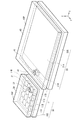
- FIG. 2 illustrates a configuration example of a main part of the distance measuring device 1.
- FIG. 2 shows the light emitting unit 10, the light receiving unit 20, the first cover unit 30, and the second cover unit 40 of the distance measuring device 1.
- 3 and 4 show a configuration example of the light emitting unit 10 and the light receiving unit 20 of the distance measuring device 1.
- the light emitting unit 10 is configured to include a light emitting unit substrate 10S and a plurality of light emitting units 11 (light emitting units 11A, 11B, 11C, 11D ”) Arranged in a matrix on the light emitting unit substrate 10S.
- 16 light-emitting bodies 11 of 4 ⁇ 4 (4 in the X-axis direction and 4 in the Y-axis direction) are arranged in the drawing, the number is not limited to this and one or more may be used. It suffices if a light emitting body is provided.
- the light emitter 11 is composed of, for example, a laser such as VCSEL or an LED.
- Part of the light emitted from the light emitting unit 10 is the light (light L1) that is guided in the direction of the distance measurement target 2 and is irradiated on the distance measurement target 2.
- the other part of the light emitted from the light emitting unit 10 is light (light that is incident on the second light receiving unit 21B of the light receiving unit 20 via the first cover unit 30 and the second cover unit 40).
- L2 The light L2 is also referred to as monitor light, and the light-emitting body that emits the light L2 is also referred to as monitor light-emitting body 11M.
- one light-emitting body 11 is shown as the monitor light-emitting body 11M, but the present invention is not limited to this, and even if two or more light-emitting bodies 11 are monitor light-emitting bodies 11M. Good. In addition, a part of the light emitted by one or two or more light emitters 11 may be used as the light for monitoring.
- the light receiving unit 20 is provided on the X axis direction side of the light emitting unit 10.
- the light receiving unit 20 is configured to include a light receiving unit substrate 20S, a first light receiving unit 21A and a second light receiving unit 21B provided on the light receiving unit substrate 20S.
- a first light receiving portion 21A is provided on the back side in the X-axis direction when viewed from the light emitting portion 10, and a second light receiving portion 21B is provided on the front side.
- Each pixel of the 1st light-receiving part 21A and the 2nd light-receiving part 21B each receives the light which injects, and outputs the electric signal according to the light-receiving amount of the light.
- the first light receiving unit 21A is a pixel array and includes, for example, n ⁇ m (m in the X-axis direction and n in the Y-axis direction) pixels (pixels A11 to Anm) arranged in a matrix. Each pixel includes a light receiving element such as a PD (photodiode).
- the second light receiving unit 21B includes one pixel. Although it is shown that the drawing has one pixel, it may have two or more pixels.
- the second light receiving portion 21B is configured by a light receiving element such as PD.
- the first light receiving portion 21A and the second light receiving portion 21B are configured as separate bodies. In the configuration of the light emitting unit 10 and the light receiving unit 20 shown in FIG.
- the second light receiving unit 21B is formed smaller than the first light receiving unit 21A in both the X-axis direction and the Y-axis direction. There is.
- the second light receiving portion 21B is provided so as to be localized at a position corresponding to the vicinity of the center of the first light receiving portion 21 in the Y-axis direction.
- the second light receiving portion 21B is located on a line (dashed-dotted line 10C) that connects the pixels forming the first light receiving portion 21A and the monitor light emitting body 11M in the shortest direction.
- FIG. 5 shows a configuration example of the first cover section 30 and the second cover section 40 of the distance measuring device 1.
- the first cover part 30 has a plate-like shape, and a first recess 32 is provided in a part thereof.
- a part of the inner wall surface of the first concave portion 32 is the first reflecting surface 31 which is an oblique surface having an angle of 45 ° with the main surface 30P of the first cover portion 30.
- the inner wall surface of the first recess 32 is in contact with air.
- the first recess 32 can be formed by counterboring or blasting.
- the recess 32 can be formed first by molding.
- the first reflecting surface 31 reflects the monitor light emitted from the monitor light emitter 11M according to the difference between the refractive index of the material forming the first cover portion 30 and the refractive index of air, The monitor light is guided in a direction different from the direction of the object 2 to be measured.
- a reflecting film made of silver or another metal film may be provided on the first reflecting surface 31.
- a light blocking material film may be provided on the first reflecting surface 31.
- the first recess 32 may be filled with a material having a refractive index different from that of the material forming the first cover portion 30.
- the first recess 32 may be filled with a light shielding material.
- the first reflection surface 31 does not necessarily have to be total reflection or high reflection.
- a part of the light emitted from the monitor light-emitting body 11M that has entered the first concave portion 32 is reflected and used as the monitor light, and the rest is transmitted to allow the distance measurement target 2 to travel.
- the light may be used as the light (light L1) that is guided in the direction and is irradiated to the distance measurement target 2.
- the second cover part 40 has a plate-like shape, and a part of the second cover part 40 is provided with a second recess 42.
- a part of the inner wall surface of the second concave portion 42 is the second reflecting surface 41 which is an oblique surface having an angle of 45 ° with the main surface 40P of the second cover portion 40.
- the inner wall surface of the second recess 42 is in contact with air.
- the second recess 42 can be formed in the same manner as the first recess 32.
- the second reflecting surface 41 is emitted from the monitor light-emitting body 11M and reflected by the first reflecting surface 31 in accordance with the difference between the refractive index of the material forming the second cover portion 40 and the refractive index of air.
- the monitor light is reflected and guided toward the second light receiving portion 21B.
- a reflecting film made of silver or another metal film may be provided on the second reflecting surface 41, or the second reflecting surface 41 may be provided.
- a light shielding material film may be provided, the second recess 42 may be filled with a material having a refractive index different from that of the material forming the second cover portion 40, or the second recess 42 may be filled with a light shielding material. But it's okay.
- the second reflection surface 41 does not necessarily have to be total reflection or high reflection.
- the first cover section 30 and the second cover section 40 are aligned so that an optical path of the monitor light L2 is provided.
- the first cover portion 30 and the second cover portion 40 are large enough to easily adjust the optical path of the monitor light L2.
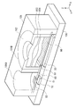
- FIG. 6 shows an example of a sectional structure of the distance measuring device 1.
- the holder 101 is arranged on the substrate 100.
- the holder 101 is provided with a light emitting portion opening 101A and a light receiving portion opening 101B.
- the packaged light emitting unit 10 is disposed on the substrate 100 inside the light emitting unit opening 101A.
- the packaged light emitting unit 10 is provided with a first cover unit 30 as a lid unit of the package.
- a first reflecting surface 31 is provided on the first cover portion 30.
- the first cover part 30 is provided with a light diffusion film 33 for diffusing light emitted from the light emitting part 10 in the direction of the object 2 to be measured.
- the light receiving section 20 is arranged on the substrate 100 inside the light receiving section opening 101B.
- the second cover section 40 is provided on the light incident side of the light receiving section 20.
- the second cover portion 40 is provided with a second reflecting surface 41.
- the second cover section 40 is provided with an infrared filter 43 for transmitting infrared light which is the light from the light emitting section 10.
- a lens holder 102 is provided inside the light receiving opening 101B.
- the lens holder 102 holds the lenses 103 and 104.
- the substrate 100 may be provided with the processing unit 50 connected to the light emitting unit 10 and the light receiving unit 20.
- the light emitting unit 10 and the light receiving unit 20 may be connected to the processing unit 50 separately provided via the substrate 100.
- further optical members can be appropriately provided in the light emitting unit opening 101A and the light receiving unit opening 101B.
- the light emitting unit 10 corresponds to a specific example of a “light emitting unit” in the present disclosure.
- the light receiving unit 20 corresponds to a specific but not limitative example of “light receiving unit” in one embodiment of the present disclosure.
- the first cover unit 30 corresponds to a specific but not limitative example of “first cover unit” in one embodiment of the present disclosure.
- the second cover section 40 corresponds to a specific but not limitative example of “second cover section” in one embodiment of the disclosure.
- the processing unit 50 corresponds to a specific but not limitative example of “processing unit” in one embodiment of the present disclosure.
- the light emitting unit 10 By driving the processing unit 50, the light emitting unit 10 emits light. Part of the light (light L1) of the light emitted from the light emitting unit 10 passes through the first cover unit 30, is guided in the direction of the distance measuring object 2, and is irradiated to the distance measuring object 2. It The light L1 is reflected by the object 2 to be measured and becomes reflected light L1R, which is incident on the first light receiving portion 21A of the light receiving portion 20. The first light receiving unit 21A receives the reflected light L1R and outputs the first pixel signal S1 to the processing unit 50.
- the processing unit 50 determines the distance measurement target 2 based on the time until the light emitted from the light emitting unit 10 is reflected by the distance measurement target 2 and enters the light reception unit 20. Calculate the distance to.
- the other part of the light emitted from the light emitting unit 10 (monitoring light L2) is reflected by the first reflecting surface 31 of the first cover unit 30 and is reflected by the second cover unit.
- the light is guided in the direction of 40, is reflected by the second reflecting surface 41 of the second cover portion 40, and is incident on the second light receiving portion 21B of the light receiving portion 20.
- the second light receiving unit 21B receives the monitoring light L2 and outputs the second pixel signal S2 to the processing unit 50.
- the processing unit 50 creates a correction value table of the measurement distance based on the second pixel signal S2 in advance.
- the processing unit 50 calculates the distance to the object 2 to be measured based on the first pixel signal S1 and refers to the correction value table to obtain the correction value corresponding to the distance obtained from the first pixel signal S1.
- the distance to the object 2 to be measured is calibrated by the obtained correction value.
- FIG. 7 shows an operation example of the distance measuring device 1.
- each light emitting body 11 of the light emitting unit 10 emits light toward the first cover unit 30.
- Part of the light (light L1) of the light that has entered the portion of the first cover portion 30 where the first recessed portion 32 is not provided passes through the first cover portion 30 and the distance measurement target 2 And is directed to the object 2 for distance measurement.
- the light L1 is reflected by the object 2 to be measured and becomes reflected light L1R, which is incident on the first light receiving portion 21A of the light receiving portion 20.
- the other part of the light (monitoring light L2) that is incident on the portion of the first cover portion 30 where the first recess 32 is provided is provided in the first recess 32.
- the light is reflected by the first reflecting surface 31 and guided toward the second cover portion 40.
- the monitoring light L2 guided to the second cover portion 40 is reflected by the second reflecting surface 41 provided in the second recess 42 and enters the second light receiving portion 21B of the light receiving portion 20. ..
- the first light receiving unit 21A receives the reflected light L1R and outputs the first pixel signal S1 to the processing unit 50.
- Each of the n ⁇ m pixels arranged in a matrix in the first light receiving unit 21A outputs the first pixel signal S1.
- the second light receiving section 21B receives the monitoring light L2 and outputs the second pixel signal S2 to the processing section 50.
- the direct method and the indirect method can be applied to the measurement of the distance to the object 2 to be measured by the distance measuring device 1 shown in FIG. 1, but the direct method will be described in the present embodiment.
- the processing unit 50 measures the time until the light emitted from the light emitting unit 10 is reflected by the distance measuring object 2 and enters the light receiving unit 20, and from the obtained time.
- the distance to the target object 2 is calculated.
- the measurement of the time until the light emitted from the light emitting unit 10 is reflected by the distance measuring object 2 and enters the light receiving unit 20 was obtained.
- the distance to the distance measuring object 2 is calculated based on time.
- the processing unit 50 calibrates the distance to the distance measurement target 2 based on the second pixel signal S2. Details of the calibration will be described later.
- the calibration of the distance to the object 2 to be measured based on the second pixel signal S2 is performed for every n ⁇ m pixels of the first light receiving unit 21A.
- the processing unit 50 causes the light emitted from the light emitting unit 10 to measure the distance based on the first pixel signal S1 output from the first light receiving unit 21A of the light receiving unit 20 in the direct method as described below.
- the time required for the light to be reflected at 2 and to enter the light receiving unit 20 is measured, and the distance between the distance measuring device 1 and the distance measuring object 2 is calculated based on the obtained time.
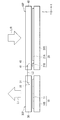
- FIG. 8A and 8B show an operation example when performing distance measurement by the distance measuring device 1 by the direct method.
- FIG. 8A shows an optical output waveform (emission pulse) of the light emitting unit 10, and FIG.
- the optical input waveform (incident pulse) of the part is shown.
- the light output waveform of the light emitting unit 10 (FIG. 8A) is an output waveform of light immediately after being emitted from the light emitting unit 10, and has a pulse shape, for example.
- the light (reflected light L1R) emitted from the light emitting unit 10 and reflected on the object 2 to be measured reaches the first light receiving unit 21A of the light receiving unit 20. It is the waveform of the light when.
- the light input waveform of the light receiving unit 20 has a pulse shape delayed by the delay time DL with respect to the pulse shape shown in FIG.
- the delay time DL corresponds to the time until the light emitted from the light emitting unit 10 is reflected by the distance measuring object 2 and is received by the light receiving unit 20. Therefore, by obtaining the delay time DL, the distance to the distance measurement target 2 can be calculated.
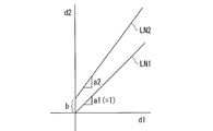
- FIG. 9 shows an example of the difference between the measured distance and the actual distance measured by the distance measuring device 1 when the present technology is applied to the direct method.
- the horizontal axis represents the actual distance d1 and the vertical axis represents the measured distance d2 before calibration.
- LN2 the relationship between the actual distance d1 and the measured distance d2 often becomes as shown by the straight line LN2.
- the slope of this straight line LN2 is "a2", and the intercept is "b”. That is, the slope and intercept of the straight line LN2 are different from the slope and intercept of the straight line LN1.
- the measurement distance is calibrated as follows.
- the processing unit 50 measures the measurement distance based on the second pixel signal S2 output from the second light receiving unit 21B according to the other part of the light (light L2 for monitoring) incident on the second light receiving unit 21B. Calibrate. Specifically, the processing unit 50 performs a correction value table creating operation and a normal operation (distance measuring).
- the correction value table creating operation is performed, for example, prior to the normal operation.
- the correction value table creating operation can be performed at any time when the normal operation is not performed.
- the processing unit 50 creates a correction value table based on the second pixel signal S2.
- the processing unit 50 detects the light receiving timing at which the second light receiving unit 21B receives the monitoring light L2 while controlling the emission timing of the monitoring light L2 to various timings. , The measurement distance corresponding to each emission timing is obtained based on the second pixel signal S2. On the other hand, the processing unit 50 obtains the actual distance by multiplying the change amount (time) of the emission timing, which is known to the processing unit 50, by the speed of light. The processing unit 50 calculates the difference between the measured distance obtained based on the second pixel signal S2 and the actual distance obtained from the change amount (time) of the emission timing. The calculated difference value is a correction value corresponding to the measurement distance obtained based on the second pixel signal S2.
- the processing unit 50 creates a correction value table by acquiring the correction value at each emission timing.
- the processing unit 50 determines the time until the light emitted from the light emitting unit 10 is reflected by the distance measurement target 2 and enters the light receiving unit 20 based on the first pixel signal S1.
- the distance to the object 2 to be measured is calculated from the measured time. For each of the n ⁇ m pixels of the first light receiving unit 21A, the measurement of the time until the light emitted from the light emitting unit 10 is reflected by the distance measuring object 2 and enters the light receiving unit 20 was obtained.
- the measurement distance to the distance measurement object 2 is calculated based on time.
- the processing unit 50 refers to a correction value table created in advance based on the second pixel signal S2 to obtain a correction value corresponding to the measurement distance obtained from the first pixel signal S1, The measurement distance to the object to be measured 2 is calibrated by the obtained correction value. The calibration of the distance to the object 2 is performed for each of the n ⁇ m pixels of the first light receiving unit 21A.
- the distance measuring device 1 in the first cover unit 30, a part of the light emitted from the light emitting unit 10 is applied to the distance measuring target 2 and the reflected light L1R thereof is received by the light receiving unit.
- the second light receiving portion 21A of the light receiving portion 20 is made incident on the first light receiving portion 21A of the light receiving portion 20 and the other part of the light is made incident on the second light receiving portion 21B of the light receiving portion 20 through the first cover portion 30 and the second cover portion 40. ..
- a correction value table used for distance calibration can be created from the second pixel signal S2 output by receiving the monitoring light L2 by the second light receiving unit 21B.
- the distance to the object 2 to be measured can be corrected with reference to the correction value table, and the accuracy of the distance to the object 2 to be measured can be improved. That is, the distance to the distance measurement target 2 can be calibrated based on the second pixel signal S2 output from the second light receiving unit 21B.
- the first cover part 30 having the first reflecting surface 31 is arranged on the light emitting side of the light emitting part 10, and the second cover part 40 having the second reflecting surface 41 receives light.
- the optical path of the monitoring light L2 can be easily provided.
- the first cover portion 30 and the second cover portion 40 have a size large enough to adjust the optical path of the monitoring light L2, the optical path of the monitoring light L2 is adjusted. Adjustment can be easily performed.
- the second pixel signal is acquired. It is possible to easily provide an optical path of light for monitoring. Therefore, the distance to the object to be measured can be easily calibrated based on the second pixel signal.
- the second light receiving portion 21B has such a size that it is localized at a position corresponding to the vicinity of the center of the first light receiving portion 21 in the Y-axis direction, but the present invention is not limited to this. It is not something that will be done.
- the second light receiving unit 21B may be elongated in one direction D (direction parallel to the Y-axis direction).
- the second reflecting surface 41 of the second cover part 40 may also extend in the one direction D, corresponding to the second light receiving portion 21B extending in the one direction D.
- FIG. 10 illustrates a configuration example of a main part of the distance measuring device 1A according to the first modification.
- the second recess 42 of the second cover portion 40 is elongated in one direction D
- the second reflecting surface 41 is provided so as to be elongated in one direction D.
- the second light receiving portion 21B is provided so as to extend in the one direction D in an elongated manner.
- One direction D in which the second reflecting surface 41 of the second cover part 40 and the second light receiving part 21B extend is, for example, the extending direction of one side of the first light receiving part 21A on the light emitting part 10 side (Y axis). Direction).
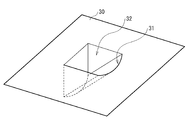
- FIG. 11 is an enlarged view showing a configuration example of the first concave portion 32 of the first cover portion 30 of the distance measuring device 1A.
- the first reflecting surface 31 of the first recess 32 provided in a part of the first cover portion 30 is provided obliquely with respect to the main surface 30P of the first cover portion 30, and further on the light receiving portion 20 side. It is a curved surface that is convex.
- the first reflecting surface 31, which is a curved surface reflects the monitoring light L2 in a direction different from the direction of the distance measurement target 2 so as to spread in the same direction as the one direction D. ..
- FIG. 12 shows a configuration example of the first light receiving unit 21A and the second light receiving unit 21B of the distance measuring device 1A.
- the second light receiving unit 21B is a single pixel having a shape elongated in the one direction D.
- the first light receiving portion 21A is the same as the first light receiving portion 21A shown in FIG.
- the monitoring light L2 of the light emitted from the light emitting unit 10 is reflected by the first reflecting surface 31 of the first cover unit 30 to be the one direction D. It is guided in the direction of the second cover part 40 so as to expand in the same direction.
- the monitor light L2 that is spread in the same direction as the one direction D is reflected by the second reflecting surface 41 that is elongated in the one direction D, and the second light reception is elongated in the one direction D.
- the light is guided in the direction of the portion 21B and enters. Except for the above, it is the same as the above embodiment.
- the monitor light L2 is spread in the same direction as the one direction D, is reflected by the second reflecting surface 41, and is elongated in the one direction D. Since it is incident on the portion 21B, the monitor light L2 is easily incident on the second light receiving portion 21B. As a result, the allowable range of alignment between the first cover portion 30 and the second cover portion 40 in the one direction D is expanded. Further, the allowable range of alignment in the one direction D between the second cover part 40 and the light receiving part 20 (second light receiving part 21B) is expanded. This makes it possible to easily adjust the optical path of the monitor light L2.
- the second light receiving unit 21B is configured as a single pixel having a shape elongated in one direction D, but the present invention is not limited to this. Instead of this, for example, the second light receiving unit 21B may include a plurality of pixels that are elongated in the one direction D.
- FIG. 13 illustrates a configuration example of the first light receiving unit 21A and the second light receiving unit 21B of the distance measuring device 1B according to the second modification.
- the second light receiving unit 21B includes a plurality of pixels (pixels B1, B2, ..., Bn) arranged in a long and narrow direction D. Although the plurality of pixels are arranged in one column in FIG. 13, they may be arranged in a plurality of columns.
- each of the plurality of pixels may have the same structure as each of the n ⁇ m pixels (pixels A11 to Anm) of the first light receiving unit 21A. it can. Except for the above, it is the same as the first modification.
- the monitor light L2 is spread in the same direction as the one direction D, is reflected by the second reflecting surface 41, and is arranged in the one direction D in a slender array. Since it is incident on the second light receiving portion 21B, the monitor light L2 is easily incident on the second light receiving portion 21B. As a result, the allowable range of alignment between the first cover portion 30 and the second cover portion 40 in the one direction D is expanded. Further, the allowable range of alignment in the one direction D between the second cover part 40 and the light receiving part 20 (second light receiving part 21B) is expanded. This makes it possible to easily adjust the optical path of the monitor light L2.
- Modification 3 In Modification 1 described above, the second recess 42 of the second cover portion 40 is elongated in the one direction D, and the second reflecting surface 41 is elongated in the one direction D. , But is not limited to this. Instead of this, for example, the end surface of the second cover portion 40 may be the second reflective surface 44.
- FIG. 14 illustrates a configuration example of a main part of a distance measuring device 1C according to Modification 3.
- the end surface of the second cover portion 40 on the light emitting unit 10 side is an oblique surface having an angle of 45 ° with the main surface 40P of the second cover portion 40, and this oblique surface is the second surface. It is the reflecting surface 44 of.
- the second reflecting surface 41 is provided so as to be elongated in one direction D.
- the second light receiving portion 21B is provided so as to extend in the one direction D in an elongated manner. Similar to Modification 1 above, except that the end surface of the second cover portion 40 is an inclined surface having an angle of 45 ° with the main surface 40P of the second cover portion 40. Is.
- the surface serving as the second reflecting surface 44 is provided on the end surface of the second cover portion 40, and the end surface of the second cover portion 40 is the main surface of the second cover portion 40. Processing into an inclined surface having an angle of 45 ° with respect to the surface 40P can be performed more easily than forming the second recess as in the first modification.
- a first reflecting surface may be provided on the end surface of the first cover portion 30. That is, the end surface of the first cover section 30 on the light receiving section 20 side is an oblique surface having an angle of 45 ° with the main surface 30P of the first cover section 30, and this oblique surface is the first reflection surface. It may be a surface. In this case, of the light emitted from the light emitting unit 10, the light incident on the end surface of the first cover unit 30 becomes the light L2 for monitoring.
- the second light receiving portion 21B is configured to extend in the one direction D in an elongated manner, but the present invention is not limited to this. Instead of this, for example, the second light receiving portion 21B has such a size that it does not extend in the one direction D elongatedly and is localized at a position corresponding to the vicinity of the center of the first light receiving portion 21 in the Y-axis direction. May have a length.
- FIG. 15 illustrates a configuration example of a main part of a distance measuring device 1D according to Modification 4.
- the end surface of the second cover portion 40 is the second reflecting surface 44 extending in the one direction D in a slender manner, and the second reflecting surface 44 is provided so as to extend in the one direction D in a slender manner.
- the second light receiving portion 21B is not elongated in the one direction D, and is provided so as to be localized at a position corresponding to the vicinity of the center of the first light receiving portion 21 in the Y-axis direction.
- One direction D in which the second reflecting surface 44 extends is, for example, the extending direction (Y-axis direction) of one side of the first light receiving unit 21A on the light emitting unit 10 side.
- the monitoring light L2 of the light emitted from the light emitting unit 10 is reflected by the first reflecting surface 31 of the first cover unit 30 and is reflected by the second cover unit. It is led in the direction of 40.
- the monitoring light L2 is reflected by the second reflecting surface 44, guided to the second light receiving portion 21B, and enters.
- the first reflecting surface 31 may reflect the monitoring light L2 so as to spread it in the one direction D, or may reflect it so as not to spread it. When the first reflecting surface 31 spreads the monitoring light L2 in the one direction D, only a part of the monitoring light L2 spread in the one direction D is incident on the second light receiving unit 21B.
- the allowable range of alignment in the one direction D between the second cover part 40 and the light receiving part 20 (second light receiving part 21B) is widened. This makes it possible to easily adjust the optical path of the monitor light L2.
- the second reflection surface 44 is not the second recess 42 but the second cover in the configuration shown in FIG. The difference is that it is provided on the end face of the portion 40.
- the end surface of the second cover portion 40 has an advantage of being easier to process than the second recess 42.
- first cover part 30 and the second cover part 40 are separate members, but the present invention is not limited to this. Instead of this, for example, the first cover portion 30 and the second cover portion 40 may be integrally configured.
- FIG. 16 illustrates a configuration example of a main part of a distance measuring device 1E according to Modification 5.
- a common cover portion 60 in which the first cover portion 30 and the second cover portion 40 are integrated is provided on the light emitting side of the light emitting portion 10 and the light incident side of the light receiving portion 20.
- the common cover part 60 is held by a holder or the like so as to be separated from the light emitting part 10 and the light receiving part 20, for example.
- the common cover part 60 is made of a material that is transparent to the light emitted from the light emitting part 10, and is made of, for example, glass or plastic.
- the common cover part 60 has a plate shape as a whole.
- the common cover part 60 prevents dust and the like from adhering to the light emitting part 10 and the light receiving part 20, and protects the light emitting part 10 and the light receiving part 20 from the external atmosphere.
- the first reflecting surface 61 is provided on a part of the common cover portion 60 on the light emitting unit 10 side.
- the first reflecting surface 61 is provided on the inner wall surface of the first recess 62 provided in a part of the common cover portion 60 on the light emitting unit 10 side.
- the first reflecting surface 61 is an oblique surface having an angle of 45 ° with the main surface 60P of the common cover part 60.
- a second reflecting surface 63 is provided on a part of the common cover portion 60 on the light receiving portion 20 side.
- the second reflecting surface 63 is provided on the inner wall surface of the second concave portion 64 provided in a part of the common cover portion 60 on the light receiving portion 20 side.
- the second reflecting surface 63 is an oblique surface having an angle of 45 ° with the main surface 60P of the common cover part 60.
- a part of the light emitted from the light emitting unit 10 passes through the common cover unit 60 and is guided in the direction of the distance measuring object 2 similarly to the light L1 shown in FIG.
- the light is reflected at 2 and again passes through the common cover portion 60 to enter the first light receiving portion 21A.
- the other part of the light emitted from the light emitting unit 10 is reflected by the first reflection surface 61 and is directed to the distance measurement target 2 in the same manner as the light L2 shown in FIG.
- Another part of the light emitted from the light emitting unit 10 is reflected by the first reflection surface 61, guided to the second reflection surface 63, and reflected by the second reflection surface 63.
- the relative positions of the first reflecting surface 61 and the second reflecting surface 63 are determined so that an optical path for entering the second light receiving portion 21B can be taken. Except for the above, it is the same as the above embodiment.
- FIG. 17 shows a configuration example of the distance measuring device 1E.
- the holder 101 is arranged on the substrate 100.
- a common cover portion 60 is provided on the light emitting side of the light emitting unit 10 and the light incident side of the light receiving unit 20.
- the common cover portion 60 is held by the holder 101.
- the first reflecting surface 61 is provided in a part of the area of the common cover part 60 that overlaps with the light emitting part 10
- the second reflecting surface 63 is in a part of the area of the light receiving part 20 that overlaps with the second light receiving part 21B.
- a light diffusion film 65 for diffusing light emitted from the light emitting unit 10 in the direction of the distance measurement target 2 is formed in a region of the common cover unit 60 overlapping the light emitting unit 10.
- An infrared filter 66 for transmitting infrared light, which is light from the light emitting unit 10, is provided in a region of the common cover unit 60 that overlaps with the light receiving unit 20.
- the common cover portion 60 is provided, and the common cover portion 60 has a configuration in which the first cover portion and the second cover portion are integrated, so the first reflection The relative position between the surface 61 and the second reflecting surface 63 has already been determined.
- An optical path for the monitoring light (light L2) can be provided by only disposing one common cover portion 60 on the light emitting side of the light emitting unit 10 and the light incident side of the light receiving unit 20.
- the alignment of the first reflecting surface 61 and the second reflecting surface 63 with respect to the light emitting unit 10 and the light receiving unit 20 is performed by adjusting the alignment between the common cover unit 60 and the light receiving unit 20 (second light receiving unit 21B).
- the optical path of the monitoring light L2 can be easily adjusted.
- a part of the inner wall surface of the first recess 32 functions as the first reflecting surface 31, and a part of the inner wall surface of the second recess 42 functions as the second reflecting surface 41.
- the present invention is not limited to this.
- a part of the first cover part 30 may be provided with a first convex part whose surface functions as a first reflecting surface, and one part of the second cover part 40 may be provided.
- the part may be provided with a second convex part whose surface functions as a second reflecting surface.
- FIG. 18 illustrates a configuration example of a main part of the distance measuring device 1F according to the modified example 6.
- the first convex portion 35 is provided on a part of the first cover portion 30, and a part of the surface of the first convex portion 35 is the first reflecting surface 34.
- the second convex portion 46 is provided on a part of the second cover portion 40, and a part of the surface of the second convex portion 46 is the second reflecting surface 45.
- a part of the light emitted from the light emitting unit 10 is transmitted through the first cover unit 30 and guided toward the distance measuring object 2 in the same manner as the light L1 shown in FIG.
- the light is reflected by the object 2 and transmitted through the second cover portion 40 to enter the first light receiving portion 21A.
- the other part of the light emitted from the light emitting unit 10 is reflected by the first reflecting surface 34 provided on the surface of the first convex portion 35 and is directed toward the object 2 to be measured.
- the light is guided in the direction of the second reflecting surface 45 which is different from the direction of the second reflecting surface 45, is reflected by the second reflecting surface 45 which is the surface of the second convex portion 46, and enters the second light receiving portion 21B.
- the first cover portion 30 and the second cover portion 40 are each provided with a convex portion having a reflecting surface. This can be preferably carried out when it is easy to form a convex shape on the surface of the cover part such as molding of plastic.
- the second light receiving portion 21B is located on the line that connects the pixels forming the first light receiving portion 21A and the monitor light emitting body 11M in the shortest distance, but the present invention is not limited to this. Not a thing.
- the second light receiving unit 21B may be provided at a position deviated from the line that connects the pixels forming the first light receiving unit 21A and the monitor light emitting body 11M in the shortest distance.
- FIG. 19 illustrates a configuration example of a light emitting unit and a light receiving unit of a distance measuring device 1G according to Modification 7.
- the second light receiving portion 21B is provided at a position deviated from the line connecting the pixels forming the first light receiving portion 21A and the monitor light emitting body 11M in the shortest distance.
- the shortest line connecting the pixels forming the first light-receiving portion 21A and the monitor light-emitting body 11M is shown by a dashed-dotted line 10C, and the second light-receiving portion 21B is provided at a position displaced from the dashed-dotted line 10C. ing.
- the angle of the first reflecting surface 31 is adjusted so that the first reflecting surface 31 reflects the monitoring light L2 toward the second reflecting surface 41.
- the second reflecting surface 41 is configured by adjusting the angle of the second reflecting surface 41 so that the light incident from the first reflecting surface 31 is reflected toward the second light receiving portion 21B.
- the second light receiving unit 21B does not necessarily have to be located on the line that connects the pixel forming the first light receiving unit 21A and the monitor light emitting body 11M in the shortest direction.
- FIG. 20 shows an operation example when distance measurement is performed by the distance measuring device 1 by the indirect method.
- A shows an optical output waveform (emission pulse) of the light emitting unit 10
- B shows an optical input waveform (incident pulse) of the light receiving portion.
- the light output waveform of the light emitting unit 10 (FIG. 20A) is a pulse waveform with a duty ratio of 50%, for example.
- the optical input waveform (FIGS. 20B and 20C) of the light receiving unit 20 has a pulse shape delayed by a predetermined time from the pulse shape shown in FIG 20A. It corresponds to the time until the light (reflected light L1R) emitted from the light emitting unit 10 and reflected by the distance measuring object 2 reaches the first light receiving unit 21A of the light receiving unit 20. Therefore, the distance measurement is performed based on the delay time. The distance to the object 2 can be calculated.
- the pixel of the first light receiving unit 21A accumulates the signal charge Q1 at an arbitrary period in the period T1 in which the light emitting unit 10 emits light, and at the same time in the period T2 in which the light emitting unit 10 does not emit light. During the period, the signal charge Q2 is accumulated and the charge ratio between the signal charge Q1 and the signal charge Q2 is obtained.
- the pixel of the first light receiving unit 21A accumulates the signal charge Q1 by detecting the incident pulse in the period TA of the period T1, and the pixel of the period T2. The signal charge Q2 is accumulated by detecting the incident pulse in the period TB. In the example of FIG.
- the charge ratio of the signal charge Q1 and the signal charge Q2 is about 3: 1, and in the example of FIG. 20C, the charge ratio of the signal charge Q1 and the signal charge Q2 is 1: 1. It is a degree.
- the charge ratio of the signal charge Q1 and the signal charge Q2 changes according to the delay time of the incident pulse. Therefore, by obtaining this charge ratio, the delay time can be obtained with high accuracy, for example, in the unit of picosecond to nanosecond. Converting the delay time into the distance to the object 2 to be measured, for example, when measuring the delay time on the order of picoseconds to nanoseconds, obtain the distance to the object 2 to be measured with a resolution of 0.3 mm to 30 cm. You can The period in which the light emitting unit 10 accumulates the signal charge Q1 in the period T1 that emits light and the period in which the light emitting unit 10 accumulates the signal charge Q2 in the period T2 that does not emit light can be appropriately changed.
- the distance to the distance measurement target 2 there may be a gap between the calculated distance (measured distance) and the actual distance (actual distance). This is due to, for example, the circuit delay in the light emitting unit 10, the light receiving unit 20, the processing unit 50, the circuit configuration of the light receiving unit 20, the shape of the emission pulse, and the like.
- FIG. 21 shows an example of the deviation between the measured distance and the actual distance measured by the distance measuring device 1 when the present technology is applied to the indirect method.
- the relationship between the actual distance d1 and the measured distance d2 often becomes as shown by the curve LN4.
- This curve LN4 has a waviness component c.
- the slope of the straight line LN5 obtained by removing the waviness component c from the curve LN4 is "a2", and the intercept is "b". That is, the slope and intercept of the straight line LN5 are different from the slope and intercept of the straight line LN3.
- the measurement distance is calibrated as follows.
- the processing unit 50 performs measurement based on the second pixel signal S2 output from the pixel of the second light receiving unit 21B according to the other part of the light (light L2 for monitoring) incident on the second light receiving unit 21B. Calibrate the distance.
- the processing unit 50 performs the correction value table creating operation and the normal operation (distance measurement) in the same manner as the operation in the direct method.
- the processing unit 50 controls the light receiving timing at which the second light receiving unit 21B receives the monitoring light L2 while performing control to change the emission timing of the monitoring light L2 to various timings.
- a correction value table is created by detecting.
- the processing unit 50 calculates the distance to the distance measurement object 2 based on the first pixel signal S1, acquires the correction value by referring to the correction value table, and measures the distance measurement object. Calibrate the measured distance up to 2.
- the present technology can also be applied to the indirect method, and the time until the light emitted from the light emitting unit 10 is reflected by the distance measuring object 2 and received by the light receiving unit 20 and the time thereof. It is possible to more accurately measure the distance from the object to the object 2 to be measured. Further, the distance to the object 2 to be measured, which is obtained by the indirect method, can be calibrated based on the second pixel signal S2 output from the second light receiving unit 21B.
- the technology according to the present disclosure (this technology) can be applied to various products.
- the technology according to the present disclosure is realized as a device mounted on any type of moving body such as an automobile, an electric vehicle, a hybrid electric vehicle, a motorcycle, a bicycle, personal mobility, an airplane, a drone, a ship, and a robot. May be.
- FIG. 22 is a block diagram showing a schematic configuration example of a vehicle control system that is an example of a mobile body control system to which the technology according to the present disclosure can be applied.
- the vehicle control system 12000 includes a plurality of electronic control units connected via a communication network 12001.
- the vehicle control system 12000 includes a drive system control unit 12010, a body system control unit 12020, a vehicle exterior information detection unit 12030, a vehicle interior information detection unit 12040, and an integrated control unit 12050.
- a microcomputer 12051, an audio / video output unit 12052, and an in-vehicle network I / F (Interface) 120. 53 is shown as a functional configuration of the integrated control unit 12050.
- the drive system control unit 12010 controls the operation of devices related to the drive system of the vehicle according to various programs.
- the drive system control unit 12010 includes a drive force generation device for generating a drive force of a vehicle such as an internal combustion engine or a drive motor, a drive force transmission mechanism for transmitting the drive force to wheels, and a steering angle of the vehicle. It functions as a steering mechanism for adjusting and a control device such as a braking device for generating a braking force of the vehicle.
- the body system control unit 12020 controls the operation of various devices mounted on the vehicle body according to various programs.
- the body system control unit 12020 functions as a keyless entry system, a smart key system, a power window device, or a control device for various lamps such as a head lamp, a back lamp, a brake lamp, a winker, or a fog lamp.
- the body system control unit 12020 can be input with radio waves or signals of various switches transmitted from a portable device that substitutes for a key.
- the body system control unit 12020 receives input of these radio waves or signals and controls the vehicle door lock device, power window device, lamp, and the like.
- the vehicle exterior information detection unit 12030 detects information outside the vehicle equipped with the vehicle control system 12000.
- the image pickup unit 12031 is connected to the vehicle exterior information detection unit 12030.
- the vehicle exterior information detection unit 12030 causes the image capturing unit 12031 to capture an image of the vehicle exterior and receives the captured image.
- the vehicle exterior information detection unit 12030 may perform object detection processing or distance detection processing such as people, vehicles, obstacles, signs, or characters on the road surface based on the received image.
- the image pickup unit 12031 is an optical sensor that receives light and outputs an electric signal according to the amount of received light.
- the image pickup unit 12031 can output the electric signal as an image or as distance measurement information.
- the light received by the imaging unit 12031 may be visible light or invisible light such as infrared light.
- the in-vehicle information detection unit 12040 detects in-vehicle information.
- a driver state detection unit 12041 that detects the state of the driver is connected.
- the driver state detection unit 12041 includes, for example, a camera that images the driver, and the in-vehicle information detection unit 12040 determines the degree of fatigue or concentration of the driver based on the detection information input from the driver state detection unit 12041. It may be calculated or it may be determined whether or not the driver is asleep.
- the microcomputer 12051 calculates the control target value of the driving force generation device, the steering mechanism or the braking device based on the information on the inside and outside of the vehicle acquired by the outside information detection unit 12030 or the inside information detection unit 12040, and the drive system control unit.
- a control command can be output to 12010.
- the microcomputer 12051 realizes functions of ADAS (Advanced Driver Assistance System) including collision avoidance or impact mitigation of a vehicle, follow-up traveling based on an inter-vehicle distance, vehicle speed maintenance traveling, a vehicle collision warning, or a vehicle lane departure warning. It is possible to perform cooperative control for the purpose.
- ADAS Advanced Driver Assistance System
- the microcomputer 12051 controls the driving force generation device, the steering mechanism, the braking device, or the like on the basis of the information around the vehicle acquired by the vehicle exterior information detection unit 12030 or the vehicle interior information detection unit 12040, so that the driver's It is possible to perform cooperative control for the purpose of autonomous driving or the like that autonomously travels without depending on the operation.
- the microcomputer 12051 can output a control command to the body system control unit 12020 based on the information outside the vehicle acquired by the outside information detection unit 12030.
- the microcomputer 12051 controls the headlamp according to the position of the preceding vehicle or the oncoming vehicle detected by the vehicle exterior information detection unit 12030, and performs cooperative control for the purpose of antiglare such as switching the high beam to the low beam. It can be carried out.
- the voice image output unit 12052 transmits an output signal of at least one of a voice and an image to an output device capable of visually or audibly notifying information to a passenger of the vehicle or the outside of the vehicle.
- an audio speaker 12061, a display unit 12062, and an instrument panel 12063 are illustrated as output devices.
- the display unit 12062 may include at least one of an on-board display and a head-up display, for example.
- FIG. 23 is a diagram showing an example of the installation position of the imaging unit 12031.
- the image capturing unit 12031 includes image capturing units 12101, 12102, 12103, 12104, and 12105.
- the image capturing units 12101, 12102, 12103, 12104, and 12105 are provided at positions such as the front nose of the vehicle 12100, the side mirrors, the rear bumper, the back door, and the upper part of the windshield inside the vehicle.
- the image capturing unit 12101 provided on the front nose and the image capturing unit 12105 provided on the upper part of the windshield in the vehicle interior mainly acquire an image in front of the vehicle 12100.
- the image capturing units 12102 and 12103 provided in the side mirrors mainly acquire images of the side of the vehicle 12100.
- the image capturing unit 12104 provided in the rear bumper or the back door mainly acquires an image behind the vehicle 12100.
- the imaging unit 12105 provided on the upper part of the windshield inside the vehicle is mainly used for detecting a preceding vehicle, a pedestrian, an obstacle, a traffic signal, a traffic sign, a lane, or the like.
- FIG. 23 shows an example of the shooting range of the imaging units 12101 to 12104.
- the imaging range 12111 indicates the imaging range of the imaging unit 12101 provided on the front nose
- the imaging ranges 12112 and 12113 indicate the imaging ranges of the imaging units 12102 and 12103 provided on the side mirrors
- the imaging range 12114 indicates The imaging range of the imaging part 12104 provided in a rear bumper or a back door is shown.
- a bird's-eye view image of the vehicle 12100 viewed from above can be obtained.
- At least one of the imaging units 12101 to 12104 may have a function of acquiring distance information.
- at least one of the image capturing units 12101 to 12104 may be a stereo camera including a plurality of image capturing elements or may be an image capturing element having pixels for phase difference detection.
- the microcomputer 12051 based on the distance information obtained from the imaging units 12101 to 12104, the distance to each three-dimensional object in the imaging range 12111 to 12114 and the temporal change of this distance (relative speed with respect to the vehicle 12100).
- the closest three-dimensional object on the traveling path of the vehicle 12100 which is traveling in the substantially same direction as the vehicle 12100 at a predetermined speed (for example, 0 km / h or more), can be extracted as a preceding vehicle. it can.
- the microcomputer 12051 can set an inter-vehicle distance to be secured in front of the preceding vehicle in advance, and can perform automatic braking control (including follow-up stop control), automatic acceleration control (including follow-up start control), and the like. In this way, it is possible to perform cooperative control for the purpose of autonomous driving, which autonomously travels without depending on the operation of the driver.
- the microcomputer 12051 uses the distance information obtained from the image capturing units 12101 to 12104 to convert three-dimensional object data regarding a three-dimensional object to other three-dimensional objects such as two-wheeled vehicles, ordinary vehicles, large vehicles, pedestrians, telephone poles, and the like. It can be classified, extracted, and used for automatic avoidance of obstacles. For example, the microcomputer 12051 distinguishes obstacles around the vehicle 12100 into obstacles visible to the driver of the vehicle 12100 and obstacles difficult to see. Then, the microcomputer 12051 determines the collision risk indicating the risk of collision with each obstacle, and when the collision risk is equal to or more than the set value and there is a possibility of collision, the microcomputer 12051 outputs the audio through the audio speaker 12061 and the display unit 12062. A driver can be assisted for avoiding a collision by outputting an alarm to the driver and performing forced deceleration or avoidance steering through the drive system control unit 12010.
- At least one of the image capturing units 12101 to 12104 may be an infrared camera that detects infrared rays.
- the microcomputer 12051 can recognize a pedestrian by determining whether or not the pedestrian is present in the images captured by the imaging units 12101 to 12104. To recognize such a pedestrian, for example, a procedure for extracting a feature point in an image captured by the image capturing units 12101 to 12104 as an infrared camera and pattern matching processing on a series of feature points indicating the contour of an object are performed to determine whether or not the pedestrian is a pedestrian.
- the voice image output unit 12052 causes the recognized pedestrian to have a rectangular contour line for emphasis.
- the display unit 12062 is controlled so as to superimpose. Further, the audio image output unit 12052 may control the display unit 12062 to display an icon indicating a pedestrian or the like at a desired position.
- the technology according to the present disclosure can be applied to the imaging unit 12031 among the configurations described above.
- the distance measuring device 1 shown in FIG. 1 can be applied to the imaging unit 12031.
- the distance measuring device for measuring the distance to the object to be measured has been described, but the present invention is not limited to this, and instead, the object is irradiated with light until it returns. It may be a time measuring device for measuring the time.
- the first light receiving portion 21A and the second light receiving portion 21B are individually provided in the above-described embodiment and modification as shown in FIG. 13 and the like, the present invention is not limited to this.
- the first light receiving unit 21A and the second light receiving unit 21B may be integrally configured as in the distance measuring device 1H shown in FIG.
- one pixel array can be divided into two regions, one of which can be the first light receiving portion 21A and the other of which can be the second light receiving portion 21B.
- each of the plurality of pixels (pixels B1, B2, ..., Bn) of the second light receiving unit 21B corresponds to each of the n ⁇ m pixels (pixels A11 to Anm) of the first light receiving unit 21A. It can have the same structure.
- the present technology can be configured as below. According to the present technology having the following configuration, it is possible to more easily provide an optical path for calibrating the distance to the object to be measured.
- the first cover part is provided obliquely with respect to the main surface of the first cover part in a part of the first cover part, and directs the second light toward the object.
- the optical module according to (1) above which has a first reflecting surface that can be reflected in a direction different from that.
- the first cover portion has a first recess provided in a part of the first cover portion, The optical module according to (2), wherein the first reflecting surface is an inner wall surface of the first recess.
- the second cover part is provided obliquely with respect to the main surface of the second cover part in a part of the second cover part, and receives the second light by the second light receiving.
- the second cover part has a second recess provided in a part of the second cover part,
- the optical module according to (5), wherein the second reflection surface is an inner wall surface of the second recess.
- the optical module according to (5), wherein the second reflecting surface is an end surface of the second cover portion.
- the second light receiving portion is provided so as to be elongated in one direction
- the first cover part is provided obliquely with respect to the main surface of the first cover part in a part of the first cover part, and the second light is directed in the same direction as the one direction. It has a first reflecting surface capable of reflecting in a direction different from the direction of the object so as to expand
- the second cover part is provided obliquely with respect to the main surface of the second cover part in a part of the second cover part, and is reflected by the first reflecting surface.
- the optical module according to any one of (1) to (7), including a second reflecting surface capable of reflecting light in the direction of the second light receiving unit.
- the optical module according to (8), wherein the second light receiving unit is a single pixel that is elongated in the one direction.
- the optical module according to (8), wherein the second light receiving unit includes a plurality of pixels arranged in a slender shape in the one direction.
- (11) The optical module according to any one of (1) to (10), wherein the first cover portion and the second cover portion are integrally formed.
- (12) The optical module according to any one of (1) to (11), wherein the first light receiving unit and the second light receiving unit are integrally configured.
- a light emitting unit capable of emitting light A light receiving section having a first light receiving section and a second light receiving section; Of the light emitted from the light emitting portion, the first light, which is provided on the light emitting side of the light emitting portion, guides a part of the light emitted from the light emitting portion toward the object.
- a first cover part capable of guiding the second light which is the other part of the light, in a direction different from the direction of the object; The first light is provided on the light-incident side of the light-receiving unit and guides the reflected light of the first light reflected by the object in the direction of the first light-receiving unit and the first light guided from the first cover unit.
- a second cover part capable of guiding the second light toward the second light receiving part;
- the distance to the object can be calculated based on the first pixel signal output from the first light receiving unit according to the reflected light that has entered the first light receiving unit, and the second distance can be calculated.
- a processing unit capable of calibrating the distance based on a second pixel signal output from the second light receiving unit according to the second light incident on the second light receiving unit. .. (14)
- the distance measuring device according to (13), wherein the processing unit can calculate the distance by a direct method.
- the distance measuring device according to (13), wherein the processing unit can calculate the distance by an indirect method.
- SYMBOLS 1 ... Distance measuring device, 2 ... Distance measuring object, 10 ... Light emitting part, 10S ... Light emitting part substrate, 11 ... Light emitting body, 20 ... Light receiving part, 20S ... Light receiving part substrate, 21A ... 1st light receiving part, 21B ... 2nd light receiving part, 30 ... 1st cover part, 30P ... Main surface, 31, 61 ... 1st reflective surface, 32, 62 ... 1st recessed part, 33, 65 ... Light diffusing film, 40 ... 2nd , 40P ... Main surface, 41, 63 ... Second reflective surface, 42, 64 ... Second recess, 43, 66 ... Infrared filter, 50 ... Processing section, 60 ...
Landscapes
- Engineering & Computer Science (AREA)
- Physics & Mathematics (AREA)
- Radar, Positioning & Navigation (AREA)
- Remote Sensing (AREA)
- Computer Networks & Wireless Communication (AREA)
- General Physics & Mathematics (AREA)
- Electromagnetism (AREA)
- Optical Radar Systems And Details Thereof (AREA)
- Measurement Of Optical Distance (AREA)
- Photo Coupler, Interrupter, Optical-To-Optical Conversion Devices (AREA)
Abstract
Description
1.実施の形態(第1及び第2のカバー部に反射面を有する凹部が設けられた例)
2.変形例1(第2のカバー部の反射面と第2の受光部が一の方向に延在するように設けられた例)
3.変形例2(第2の受光部が複数の画素を含むように設けられた例)
4.変形例3(第2のカバー部の反射面と第2の受光部が一の方向に延在するように設けられた例)
5.変形例4(第2のカバー部の反射面が一の方向に延在するように設けられた例)
6.変形例5(第1及び第2のカバー部が一体に構成されている例)
7.変形例6(第1及び第2のカバー部に反射面を有する凸部が設けられた例)
8.変形例7(第2の受光部の位置が、第1の受光部を構成する画素とモニタ用の発光体とを最短で結ぶ線上からはずれている例)
9.変形例8(インダイレクト方式により測距を行う例)
10.移動体への応用例
[構成例]
図1は、一実施の形態に係る測距装置(測距装置1)の一構成例を表すものである。測距装置1は、測距対象物2に光L1を照射し、測距対象物2において反射した反射光L1Rを検出し、その検出結果に基づいて測距対象物2までの距離を計測する装置である。測距装置1は、発光部10と、受光部20と、第1のカバー部30と、第2のカバー部40と、処理部50とを備える。測距装置1のうちの、発光部10、受光部20、第1のカバー部30、および第2のカバー部40が、光モジュールとして構成されていてもよい。
より構成することができる。発光部10から発せられる光は、例えば赤外光である。また、発光部10から発せられる光は、例えばパルス光である。発光部10から発せられた光のうちの一部の光(光L1)は、第1のカバー部30を経て外部に出射され、測距対象物2に照射されるようになっている。
0は、第1のカバー部30と第2のカバー部40を経て受光部20の第2の受光部21Bに入射した光L2に応じて第2の受光部21Bから出力される第2の画素信号S2に基づき、測距装置1と測距対象物2との間の距離を較正するようになっている。
図2は、測距装置1の要部の一構成例を表すものである。この図2は、測距装置1のうちの、発光部10、受光部20、第1のカバー部30、および第2のカバー部40を示している。図3,4は、測距装置1の発光部10と受光部20の一構成例を表すものである。
受光部20に接続された処理部50が設けられていてもよい。あるいは、発光部10及び受光部20は、基板100を介して別途設けられている処理部50に接続されていてもよい。また、発光部用開口部101A及び受光部用開口部101Bには、上記以外にさらなる光学部材を適宜設けることができる。
続いて、本実施の形態の測距装置の動作及び作用について説明する。
まず、図1を参照して、測距装置の全体動作概要を説明する。処理部50の駆動により、発光部10は光を出射する。発光部10から発せられた光のうちの一部の光(光L1)は、第1のカバー部30を透過して測距対象物2の方向に導かれ、測距対象物2に照射される。光L1は測距対象物2において反射して反射光L1Rとなり、受光部20の第1の受光部21Aに入射する。第1の受光部21Aは、反射光L1Rを受光して第1の画素信号S1を処理部50に出力する。処理部50は、第1の画素信号S1に基づき、発光部10から発せられた光が測距対象物2において反射して受光部20に入射するまでの時間に基づいて、測距対象物2までの距離を算出する。一方、発光部10から発せられた光のうちの他の一部の光(モニタ用の光L2)は、第1のカバー部30の第1の反射面31において反射して第2のカバー部40の方向に導かれ、第2のカバー部40の第2の反射面41において反射して受光部20の第2の受光部21Bに入射する。第2の受光部21Bは、モニタ用の光L2を受光して第2の画素信号S2を処理部50に出力する。処理部50は、予め、第2の画素信号S2に基づき測定距離の補正値テーブルを作成する。処理部50は、第1の画素信号S1に基づき測距対象物2までの距離を算出し、補正値テーブルを参照して第1の画素信号S1から得られる距離に対応する補正値を取得し、得られた補正値により測距対象物2までの距離を較正する。
図7は、測距装置1の一動作例を表すものである。処理部50の駆動により、発光部10の各発光体11は、第1のカバー部30の方向へ光を出射する。
以上のように本実施の形態では、第1の反射面を有する第1のカバー部と第2の反射面を有する第2のカバー部を備えるようにしたので、第2の画素信号を取得するためのモニタ用の光の光学経路を容易に設けることができる。このため、第2の画素信号に基づき測距対象物までの距離の較正を容易に行うことができる。
上記の実施の形態では、第2の受光部21Bが、Y軸方向における第1の受光部21の中央付近に対応する位置に局在するような大きさを有するようにしたが、これに限定されるものではない。これに代えて、例えば、第2の受光部21Bが、一の方向D(Y軸方向と平行な方向)に細長く延在するようにしてもよい。また、一の方向D延在する第2の受光部21Bに対応して、第2のカバー部40の第2の反射面41も一の方向Dに延在していてもよい。
上記の変形例1では、第2の受光部21Bは一の方向Dに細長く延在する形状の単一の画素である構成としたが、これに限定されるものではない。これに代えて、例えば、第2の受光部21Bは一の方向Dに細長く配列された複数の画素を含んでいてもよい。
上記の変形例1では、第2のカバー部40の第2の凹部42が一の方向Dに細長く延在し、第2の反射面41が一の方向Dに細長く延在するようにしたが、これに限定されるものではない。これに代えて、例えば、第2のカバー部40の端面が第2の反射面44であってもよい。
上記の変形例3では、第2の受光部21Bが一の方向Dに細長く延在するようにしたが、これに限定されるものではない。これに代えて、例えば、第2の受光部21Bが、一の方向Dに細長く延在せず、Y軸方向における第1の受光部21の中央付近に対応する位置に局在するような大きさを有していてもよい。
上記の実施の形態では、第1のカバー部30と第2のカバー部40とは別々の部材であるが、これに限定されるものではない。これに代えて、例えば、第1のカバー部30と第2のカバー部40とは一体に構成されていてもよい。
上記の実施の形態では、第1の凹部32の内壁面の一部を第1の反射面31として機能させるとともに、第2の凹部42の内壁面の一部を第2の反射面41として機能させたが、これに限定されるものではない。これに代えて、例えば、第1のカバー部30の一部に、表面が第1の反射面として機能する第1の凸部が設けられてもよく、また、第2のカバー部40の一部に表面が第2の反射面として機能する第2の凸部が設けられてもよい。
上記の実施の形態では、第2の受光部21Bが、第1の受光部21Aを構成する画素とモニタ用の発光体11Mとを最短で結ぶ線上に位置しているが、これに限定されるものではない。これに代えて、例えば、第2の受光部21Bが、第1の受光部21Aを構成する画素とモニタ用の発光体11Mとを最短で結ぶ線上からずれた位置に設けられていてもよい。
上記の実施の形態では、測距装置1による測距対象物2までの距離の測定をダイレクト方式で行う例で説明したが、これに限定されるものではない。これに代えて、例えば、この距離の測定をインダイレクト方式で行ってもよい。この距離の測定をインダイレクト方式により行う例について以下に説明する。
本開示に係る技術(本技術)は、様々な製品へ応用することができる。例えば、本開示に係る技術は、自動車、電気自動車、ハイブリッド電気自動車、自動二輪車、自転車、パーソナルモビリティ、飛行機、ドローン、船舶、ロボット等のいずれかの種類の移動体に搭載される装置として実現されてもよい。
53が図示されている。
んでいてもよい。
第1の受光部と第2の受光部とを有する受光部と、
前記発光部の光出射側に設けられ、前記発光部から発せられた光のうちの一部の光である第1の光を対象物の方向に導くとともに前記発光部から発せられた光のうちの他の一部の光である第2の光を前記対象物の方向とは異なる方向に導くことが可能な第1のカバー部と、
前記受光部の光入射側に設けられ、前記第1の光が前記対象物において反射された反射光を前記第1の受光部の方向に導くとともに前記第1のカバー部から導かれた前記第2の光を前記第2の受光部の方向に導くことが可能な第2のカバー部と
を備えた光モジュール。
(2)前記第1のカバー部は、前記第1のカバー部の一部において、前記第1のカバー部の主面に対して斜めに設けられ、前記第2の光を前記対象物の方向とは異なる方向に反射させることが可能な第1の反射面を有する
前記(1)に記載の光モジュール。
(3)前記第1のカバー部は、前記第1のカバー部の一部に設けられた第1の凹部を有し、
前記第1の反射面は、前記第1の凹部の内壁面である
前記(2)に記載の光モジュール。
(4)前記第1の反射面は、前記第1のカバー部の端面である
前記(2)に記載の光モジュール。
(5)前記第2のカバー部は、前記第2のカバー部の一部において、前記第2のカバー部の主面に対して斜めに設けられ、前記第2の光を前記第2の受光部の方向に反射させることが可能な第2の反射面を有する
前記(1)から(4)のいずれかに記載の光モジュール。
(6)前記第2のカバー部は、前記第2のカバー部の一部に設けられた第2の凹部を有し、
前記第2の反射面は、前記第2の凹部の内壁面である
前記(5)に記載の光モジュール。
(7)前記第2の反射面は、前記第2のカバー部の端面である
前記(5)に記載の光モジュール。
(8)前記第2の受光部は、一の方向に細長く延在するように設けられ、
前記第1のカバー部は、前記第1のカバー部の一部において、前記第1のカバー部の主面に対して斜めに設けられ、前記第2の光を前記一の方向と同じ方向に拡げるように前記対象物の方向とは異なる方向に反射させることが可能な第1の反射面を有し、
前記第2のカバー部は、前記第2のカバー部の一部において、前記第2のカバー部の主面に対して斜めに設けられ、前記第1の反射面において反射された前記第2の光を前記第2の受光部の方向に反射させることが可能な第2の反射面を有する
前記(1)から(7)のいずれかに記載の光モジュール。
(9)前記第2の受光部は、前記一の方向に細長く延在する形状の単一の画素である
前記(8)に記載の光モジュール。
(10)前記第2の受光部は、前記一の方向に細長く配列された複数の画素を含む
前記(8)に記載の光モジュール。
(11)前記第1のカバー部および前記第2のカバー部は一体に構成されている
前記(1)から(10)のいずれかに記載の光モジュール。
(12)前記第1の受光部および前記第2の受光部は一体に構成されている
前記(1)から(11)のいずれかに記載の光モジュール。
(13)光を発することが可能な発光部と、
第1の受光部と第2の受光部とを有する受光部と、
前記発光部の光出射側に設けられ、前記発光部から発せられた光のうちの一部の光である第1の光を対象物の方向に導くとともに前記発光部から発せられた光のうちの他の一部の光である第2の光を前記対象物の方向とは異なる方向に導くことが可能な第1のカバー部と、
前記受光部の光入射側に設けられ、前記第1の光が前記対象物において反射された反射光を前記第1の受光部の方向に導くとともに前記第1のカバー部から導かれた前記第2の光を前記第2の受光部の方向に導くことが可能な第2のカバー部と、
前記第1の受光部に入射した前記反射光に応じて前記第1の受光部から出力される第1の画素信号に基づき前記対象物までの距離を算出することが可能であり、前記第2の受光部に入射した前記第2の光に応じて前記第2の受光部から出力される第2の画素信号に基づき前記距離を較正することが可能である処理部と
を備えた測距装置。
(14)前記処理部は、ダイレクト方式で前記距離を算出することが可能である
前記(13)に記載の測距装置。
(15)前記処理部は、インダイレクト方式で前記距離を算出することが可能である
前記(13)に記載の測距装置。
Claims (15)
- 光を発することが可能な発光部と、
第1の受光部と第2の受光部とを有する受光部と、
前記発光部の光出射側に設けられ、前記発光部から発せられた光のうちの一部の光である第1の光を対象物の方向に導くとともに前記発光部から発せられた光のうちの他の一部の光である第2の光を前記対象物の方向とは異なる方向に導くことが可能な第1のカバー部と、
前記受光部の光入射側に設けられ、前記第1の光が前記対象物において反射された反射光を前記第1の受光部の方向に導くとともに前記第1のカバー部から導かれた前記第2の光を前記第2の受光部の方向に導くことが可能な第2のカバー部と
を備えた光モジュール。 - 前記第1のカバー部は、前記第1のカバー部の一部において、前記第1のカバー部の主面に対して斜めに設けられ、前記第2の光を前記対象物の方向とは異なる方向に反射させることが可能な第1の反射面を有する
請求項1に記載の光モジュール。 - 前記第1のカバー部は、前記第1のカバー部の一部に設けられた第1の凹部を有し、
前記第1の反射面は、前記第1の凹部の内壁面である
請求項2に記載の光モジュール。 - 前記第1の反射面は、前記第1のカバー部の端面である
請求項2に記載の光モジュール。 - 前記第2のカバー部は、前記第2のカバー部の一部において、前記第2のカバー部の主面に対して斜めに設けられ、前記第2の光を前記第2の受光部の方向に反射させることが可能な第2の反射面を有する
請求項1に記載の光モジュール。 - 前記第2のカバー部は、前記第2のカバー部の一部に設けられた第2の凹部を有し、
前記第2の反射面は、前記第2の凹部の内壁面である
請求項5に記載の光モジュール。 - 前記第2の反射面は、前記第2のカバー部の端面である
請求項5に記載の光モジュール。 - 前記第2の受光部は、一の方向に細長く延在するように設けられ、
前記第1のカバー部は、前記第1のカバー部の一部において、前記第1のカバー部の主面に対して斜めに設けられ、前記第2の光を前記一の方向と同じ方向に拡げるように前記対象物の方向とは異なる方向に反射させることが可能な第1の反射面を有し、
前記第2のカバー部は、前記第2のカバー部の一部において、前記第2のカバー部の主面に対して斜めに設けられ、前記第1の反射面において反射された前記第2の光を前記第2の受光部の方向に反射させることが可能な第2の反射面を有する
請求項1に記載の光モジュール。 - 前記第2の受光部は、前記一の方向に細長く延在する形状の単一の画素である
請求項8に記載の光モジュール。 - 前記第2の受光部は、前記一の方向に細長く配列された複数の画素を含む
請求項8に記載の光モジュール。 - 前記第1のカバー部および前記第2のカバー部は一体に構成されている
請求項1に記載の光モジュール。 - 前記第1の受光部および前記第2の受光部は一体に構成されている
請求項1に記載の光モジュール。 - 光を発することが可能な発光部と、
第1の受光部と第2の受光部とを有する受光部と、
前記発光部の光出射側に設けられ、前記発光部から発せられた光のうちの一部の光である第1の光を対象物の方向に導くとともに前記発光部から発せられた光のうちの他の一部の光である第2の光を前記対象物の方向とは異なる方向に導くことが可能な第1のカバー部と、
前記受光部の光入射側に設けられ、前記第1の光が前記対象物において反射された反射光を前記第1の受光部の方向に導くとともに前記第1のカバー部から導かれた前記第2の光を前記第2の受光部の方向に導くことが可能な第2のカバー部と、
前記第1の受光部に入射した前記反射光に応じて前記第1の受光部から出力される第1の画素信号に基づき前記対象物までの距離を算出することが可能であり、前記第2の受光部に入射した前記第2の光に応じて前記第2の受光部から出力される第2の画素信号に基づき前記距離を較正することが可能である処理部と
を備えた測距装置。 - 前記処理部は、ダイレクト方式で前記距離を算出することが可能である
請求項13に記載の測距装置。 - 前記処理部は、インダイレクト方式で前記距離を算出することが可能である
請求項13に記載の測距装置。
Priority Applications (4)
| Application Number | Priority Date | Filing Date | Title |
|---|---|---|---|
| DE112019005636.0T DE112019005636B4 (de) | 2018-11-12 | 2019-10-17 | Optisches modul und abstandsmessvorrichtung |
| CN201980070911.2A CN112956034B (zh) | 2018-11-12 | 2019-10-17 | 光学模块和测距装置 |
| US17/290,837 US20220003866A1 (en) | 2018-11-12 | 2019-10-17 | Optical module and distance-measuring device |
| JP2020556727A JP7441796B2 (ja) | 2018-11-12 | 2019-10-17 | 光モジュール及び測距装置 |
Applications Claiming Priority (2)
| Application Number | Priority Date | Filing Date | Title |
|---|---|---|---|
| JP2018212133 | 2018-11-12 | ||
| JP2018-212133 | 2018-11-12 |
Publications (1)
| Publication Number | Publication Date |
|---|---|
| WO2020100514A1 true WO2020100514A1 (ja) | 2020-05-22 |
Family
ID=70730885
Family Applications (1)
| Application Number | Title | Priority Date | Filing Date |
|---|---|---|---|
| PCT/JP2019/040888 Ceased WO2020100514A1 (ja) | 2018-11-12 | 2019-10-17 | 光モジュール及び測距装置 |
Country Status (5)
| Country | Link |
|---|---|
| US (1) | US20220003866A1 (ja) |
| JP (1) | JP7441796B2 (ja) |
| CN (1) | CN112956034B (ja) |
| DE (1) | DE112019005636B4 (ja) |
| WO (1) | WO2020100514A1 (ja) |
Families Citing this family (4)
| Publication number | Priority date | Publication date | Assignee | Title |
|---|---|---|---|---|
| US20230052228A1 (en) * | 2019-12-24 | 2023-02-16 | Ams International Ag | Time of flight sensor |
| FR3109245B1 (fr) * | 2020-04-08 | 2022-04-29 | St Microelectronics Grenoble 2 | Dispositif électronique comprenant une structure d’encapsulation transparente logeant une puce électronique et procédé de fabrication correspondant |
| WO2024130642A1 (zh) * | 2022-12-22 | 2024-06-27 | 华为技术有限公司 | 一种发射装置、探测装置及终端 |
| US20240219524A1 (en) * | 2022-12-30 | 2024-07-04 | Advanced Semiconductor Engineering, Inc. | Optical module |
Citations (9)
| Publication number | Priority date | Publication date | Assignee | Title |
|---|---|---|---|---|
| WO2006016504A1 (ja) * | 2004-08-09 | 2006-02-16 | Omron Corporation | 光電センサ用の光学素子およびこれを用いた光電センサ |
| JP2006147836A (ja) * | 2004-11-19 | 2006-06-08 | Sharp Corp | 光半導体装置および光半導体装置の製造方法 |
| JP2008003075A (ja) * | 2006-05-24 | 2008-01-10 | Sharp Corp | 光学式測距装置およびその製造方法 |
| JP2010286448A (ja) * | 2009-06-15 | 2010-12-24 | Nippon Signal Co Ltd:The | 光測距装置 |
| US20160124089A1 (en) * | 2014-10-31 | 2016-05-05 | Cedes Safety & Automation Ag | Absolute distance measurement for time-of-flight sensors |
| JP2017147400A (ja) * | 2016-02-19 | 2017-08-24 | ローム株式会社 | 受発光装置 |
| WO2017169122A1 (ja) * | 2016-03-30 | 2017-10-05 | ソニー株式会社 | 光電変換素子および光電変換装置 |
| WO2017209206A1 (ja) * | 2016-06-01 | 2017-12-07 | シャープ株式会社 | 光検出装置、及び電子機器 |
| WO2018131514A1 (ja) * | 2017-01-13 | 2018-07-19 | ソニー株式会社 | 信号処理装置、信号処理方法、およびプログラム |
Family Cites Families (10)
| Publication number | Priority date | Publication date | Assignee | Title |
|---|---|---|---|---|
| US6445491B2 (en) * | 1999-01-29 | 2002-09-03 | Irma America, Inc. | Method and apparatus for optical sectioning and imaging using time-gated parametric image amplification |
| US6835923B2 (en) * | 2001-11-16 | 2004-12-28 | Nokia Corporation | Method and apparatus for self-monitoring of proximity sensors |
| US7165896B2 (en) * | 2004-02-12 | 2007-01-23 | Hymite A/S | Light transmitting modules with optical power monitoring |
| DE102005043418A1 (de) * | 2005-09-13 | 2007-03-22 | Robert Bosch Gmbh | Elektro-optisches Messgerät |
| DE102011005740A1 (de) * | 2011-03-17 | 2012-09-20 | Robert Bosch Gmbh | Messvorrichtung zur Messung einer Entfernung zwischen der Messvorrichtung und einem Zielobjekt mit Hilfe optischer Messstrahlung |
| US9366752B2 (en) * | 2011-09-23 | 2016-06-14 | Apple Inc. | Proximity sensor with asymmetric optical element |
| WO2014188756A1 (ja) * | 2013-05-22 | 2014-11-27 | シャープ株式会社 | 光センサおよび表示装置 |
| EP2827099A1 (de) * | 2013-07-16 | 2015-01-21 | Leica Geosystems AG | Lasertracker mit Zielsuchfunktionalität |
| JP6359848B2 (ja) * | 2014-03-18 | 2018-07-18 | 株式会社エンプラス | 光レセプタクルおよびこれを備えた光モジュール |
| CN104122542A (zh) * | 2014-07-30 | 2014-10-29 | 杜学璋 | 一种激光测距的校准方法、校准装置及测量仪器 |
-
2019
- 2019-10-17 WO PCT/JP2019/040888 patent/WO2020100514A1/ja not_active Ceased
- 2019-10-17 DE DE112019005636.0T patent/DE112019005636B4/de active Active
- 2019-10-17 US US17/290,837 patent/US20220003866A1/en active Pending
- 2019-10-17 JP JP2020556727A patent/JP7441796B2/ja active Active
- 2019-10-17 CN CN201980070911.2A patent/CN112956034B/zh active Active
Patent Citations (9)
| Publication number | Priority date | Publication date | Assignee | Title |
|---|---|---|---|---|
| WO2006016504A1 (ja) * | 2004-08-09 | 2006-02-16 | Omron Corporation | 光電センサ用の光学素子およびこれを用いた光電センサ |
| JP2006147836A (ja) * | 2004-11-19 | 2006-06-08 | Sharp Corp | 光半導体装置および光半導体装置の製造方法 |
| JP2008003075A (ja) * | 2006-05-24 | 2008-01-10 | Sharp Corp | 光学式測距装置およびその製造方法 |
| JP2010286448A (ja) * | 2009-06-15 | 2010-12-24 | Nippon Signal Co Ltd:The | 光測距装置 |
| US20160124089A1 (en) * | 2014-10-31 | 2016-05-05 | Cedes Safety & Automation Ag | Absolute distance measurement for time-of-flight sensors |
| JP2017147400A (ja) * | 2016-02-19 | 2017-08-24 | ローム株式会社 | 受発光装置 |
| WO2017169122A1 (ja) * | 2016-03-30 | 2017-10-05 | ソニー株式会社 | 光電変換素子および光電変換装置 |
| WO2017209206A1 (ja) * | 2016-06-01 | 2017-12-07 | シャープ株式会社 | 光検出装置、及び電子機器 |
| WO2018131514A1 (ja) * | 2017-01-13 | 2018-07-19 | ソニー株式会社 | 信号処理装置、信号処理方法、およびプログラム |
Also Published As
| Publication number | Publication date |
|---|---|
| CN112956034B (zh) | 2025-05-27 |
| JPWO2020100514A1 (ja) | 2021-10-07 |
| DE112019005636T5 (de) | 2021-07-29 |
| DE112019005636B4 (de) | 2025-04-30 |
| JP7441796B2 (ja) | 2024-03-01 |
| US20220003866A1 (en) | 2022-01-06 |
| CN112956034A (zh) | 2021-06-11 |
Similar Documents
| Publication | Publication Date | Title |
|---|---|---|
| JP7441796B2 (ja) | 光モジュール及び測距装置 | |
| US12164029B2 (en) | Time measurement device and time measurement apparatus | |
| JP7321834B2 (ja) | 照明装置、および、測距モジュール | |
| WO2018101262A1 (ja) | 測距装置及び測距方法 | |
| JP7494200B2 (ja) | 照明装置、照明装置の制御方法、および、測距モジュール | |
| KR20210080270A (ko) | 측거 센서, 검출 센서, 측거 방법, 및 전자 디바이스 | |
| US20220352227A1 (en) | Semiconductor package and electronic device | |
| WO2020184233A1 (ja) | 光源モジュール、測距装置及び制御方法 | |
| WO2021065494A1 (ja) | 測距センサ、信号処理方法、および、測距モジュール | |
| WO2021065495A1 (ja) | 測距センサ、信号処理方法、および、測距モジュール | |
| WO2020031660A1 (ja) | 車載カメラ、及びこれを用いた駆動制御システム | |
| WO2022034844A1 (ja) | 面発光レーザ装置及び電子機器 | |
| WO2020189101A1 (ja) | 測距装置 | |
| EP4524609A1 (en) | Ranging device | |
| US11579369B2 (en) | Optical communication connector, optical communication cable, and electronic device | |
| WO2021145261A1 (ja) | 受光装置及び電子システム | |
| US20230341556A1 (en) | Distance measurement sensor, signal processing method, and distance measurement module | |
| WO2020189091A1 (ja) | 光モジュールおよび測距装置 | |
| WO2024075409A1 (en) | Photodetection device | |
| US20230375800A1 (en) | Semiconductor device and optical structure body | |
| WO2025033091A1 (ja) | 発光素子および測距装置 | |
| WO2023079830A1 (ja) | 測距装置、および、光検出素子 | |
| WO2021145212A1 (ja) | 測距センサ、測距システム、および、電子機器 |
Legal Events
| Date | Code | Title | Description |
|---|---|---|---|
| 121 | Ep: the epo has been informed by wipo that ep was designated in this application |
Ref document number: 19885557 Country of ref document: EP Kind code of ref document: A1 |
|
| ENP | Entry into the national phase |
Ref document number: 2020556727 Country of ref document: JP Kind code of ref document: A |
|
| 122 | Ep: pct application non-entry in european phase |
Ref document number: 19885557 Country of ref document: EP Kind code of ref document: A1 |
|
| WWG | Wipo information: grant in national office |
Ref document number: 112019005636 Country of ref document: DE |
|
| WWG | Wipo information: grant in national office |
Ref document number: 201980070911.2 Country of ref document: CN |