WO2020100435A1 - 符号化装置、復号装置、符号化システム、学習方法、及びプログラム - Google Patents
符号化装置、復号装置、符号化システム、学習方法、及びプログラム Download PDFInfo
- Publication number
- WO2020100435A1 WO2020100435A1 PCT/JP2019/037254 JP2019037254W WO2020100435A1 WO 2020100435 A1 WO2020100435 A1 WO 2020100435A1 JP 2019037254 W JP2019037254 W JP 2019037254W WO 2020100435 A1 WO2020100435 A1 WO 2020100435A1
- Authority
- WO
- WIPO (PCT)
- Prior art keywords
- data
- encoded data
- image
- target size
- unit
- Prior art date
- Legal status (The legal status is an assumption and is not a legal conclusion. Google has not performed a legal analysis and makes no representation as to the accuracy of the status listed.)
- Ceased
Links
Images




Classifications
-
- G—PHYSICS
- G06—COMPUTING OR CALCULATING; COUNTING
- G06T—IMAGE DATA PROCESSING OR GENERATION, IN GENERAL
- G06T9/00—Image coding
- G06T9/002—Image coding using neural networks
-
- G—PHYSICS
- G06—COMPUTING OR CALCULATING; COUNTING
- G06N—COMPUTING ARRANGEMENTS BASED ON SPECIFIC COMPUTATIONAL MODELS
- G06N3/00—Computing arrangements based on biological models
- G06N3/02—Neural networks
- G06N3/08—Learning methods
- G06N3/084—Backpropagation, e.g. using gradient descent
-
- G—PHYSICS
- G06—COMPUTING OR CALCULATING; COUNTING
- G06N—COMPUTING ARRANGEMENTS BASED ON SPECIFIC COMPUTATIONAL MODELS
- G06N3/00—Computing arrangements based on biological models
- G06N3/02—Neural networks
- G06N3/04—Architecture, e.g. interconnection topology
- G06N3/045—Combinations of networks
-
- G—PHYSICS
- G06—COMPUTING OR CALCULATING; COUNTING
- G06N—COMPUTING ARRANGEMENTS BASED ON SPECIFIC COMPUTATIONAL MODELS
- G06N3/00—Computing arrangements based on biological models
- G06N3/02—Neural networks
- G06N3/04—Architecture, e.g. interconnection topology
- G06N3/045—Combinations of networks
- G06N3/0455—Auto-encoder networks; Encoder-decoder networks
-
- G—PHYSICS
- G06—COMPUTING OR CALCULATING; COUNTING
- G06N—COMPUTING ARRANGEMENTS BASED ON SPECIFIC COMPUTATIONAL MODELS
- G06N3/00—Computing arrangements based on biological models
- G06N3/02—Neural networks
- G06N3/04—Architecture, e.g. interconnection topology
- G06N3/0464—Convolutional networks [CNN, ConvNet]
-
- G—PHYSICS
- G06—COMPUTING OR CALCULATING; COUNTING
- G06N—COMPUTING ARRANGEMENTS BASED ON SPECIFIC COMPUTATIONAL MODELS
- G06N3/00—Computing arrangements based on biological models
- G06N3/02—Neural networks
- G06N3/04—Architecture, e.g. interconnection topology
- G06N3/0495—Quantised networks; Sparse networks; Compressed networks
-
- G—PHYSICS
- G06—COMPUTING OR CALCULATING; COUNTING
- G06N—COMPUTING ARRANGEMENTS BASED ON SPECIFIC COMPUTATIONAL MODELS
- G06N3/00—Computing arrangements based on biological models
- G06N3/02—Neural networks
- G06N3/08—Learning methods
-
- G—PHYSICS
- G06—COMPUTING OR CALCULATING; COUNTING
- G06N—COMPUTING ARRANGEMENTS BASED ON SPECIFIC COMPUTATIONAL MODELS
- G06N3/00—Computing arrangements based on biological models
- G06N3/02—Neural networks
- G06N3/08—Learning methods
- G06N3/09—Supervised learning
-
- G—PHYSICS
- G06—COMPUTING OR CALCULATING; COUNTING
- G06T—IMAGE DATA PROCESSING OR GENERATION, IN GENERAL
- G06T7/00—Image analysis
- G06T7/60—Analysis of geometric attributes
- G06T7/62—Analysis of geometric attributes of area, perimeter, diameter or volume
-
- H—ELECTRICITY
- H04—ELECTRIC COMMUNICATION TECHNIQUE
- H04N—PICTORIAL COMMUNICATION, e.g. TELEVISION
- H04N19/00—Methods or arrangements for coding, decoding, compressing or decompressing digital video signals
- H04N19/10—Methods or arrangements for coding, decoding, compressing or decompressing digital video signals using adaptive coding
- H04N19/102—Methods or arrangements for coding, decoding, compressing or decompressing digital video signals using adaptive coding characterised by the element, parameter or selection affected or controlled by the adaptive coding
- H04N19/132—Sampling, masking or truncation of coding units, e.g. adaptive resampling, frame skipping, frame interpolation or high-frequency transform coefficient masking
-
- H—ELECTRICITY
- H04—ELECTRIC COMMUNICATION TECHNIQUE
- H04N—PICTORIAL COMMUNICATION, e.g. TELEVISION
- H04N19/00—Methods or arrangements for coding, decoding, compressing or decompressing digital video signals
- H04N19/10—Methods or arrangements for coding, decoding, compressing or decompressing digital video signals using adaptive coding
- H04N19/134—Methods or arrangements for coding, decoding, compressing or decompressing digital video signals using adaptive coding characterised by the element, parameter or criterion affecting or controlling the adaptive coding
- H04N19/146—Data rate or code amount at the encoder output
-
- H—ELECTRICITY
- H04—ELECTRIC COMMUNICATION TECHNIQUE
- H04N—PICTORIAL COMMUNICATION, e.g. TELEVISION
- H04N19/00—Methods or arrangements for coding, decoding, compressing or decompressing digital video signals
- H04N19/10—Methods or arrangements for coding, decoding, compressing or decompressing digital video signals using adaptive coding
- H04N19/169—Methods or arrangements for coding, decoding, compressing or decompressing digital video signals using adaptive coding characterised by the coding unit, i.e. the structural portion or semantic portion of the video signal being the object or the subject of the adaptive coding
- H04N19/184—Methods or arrangements for coding, decoding, compressing or decompressing digital video signals using adaptive coding characterised by the coding unit, i.e. the structural portion or semantic portion of the video signal being the object or the subject of the adaptive coding the unit being bits, e.g. of the compressed video stream
-
- H—ELECTRICITY
- H04—ELECTRIC COMMUNICATION TECHNIQUE
- H04N—PICTORIAL COMMUNICATION, e.g. TELEVISION
- H04N19/00—Methods or arrangements for coding, decoding, compressing or decompressing digital video signals
- H04N19/90—Methods or arrangements for coding, decoding, compressing or decompressing digital video signals using coding techniques not provided for in groups H04N19/10-H04N19/85, e.g. fractals
Definitions
- the present invention relates to an encoding device, a decoding device, an encoding system, a learning method, and a program.
- the present application claims priority based on Japanese Patent Application No. 2018-213791 filed in Japan on November 14, 2018, and the content thereof is incorporated herein.
- the auto encoder includes an encoder that obtains a feature amount from input data and a decoder that obtains data close to the input data from the feature amount.
- the encoder and the decoder are constructed by arbitrary arithmetic units. For example, when the input data is an image, the encoder is composed of a combination of a plurality of arithmetic units performing a convolution operation and a non-linear converter, and the decoder is a combination of a plurality of arithmetic units performing an inverse operation of the convolution operation by the encoder and a non-linear converter.
- the encoder is composed of a combination of a plurality of arithmetic units performing a convolution operation and a non-linear converter
- the decoder is a combination of a plurality of arithmetic units performing an inverse operation of the convolution operation by the encoder and a non-linear converter.
- a system using a neural network including an auto encoder it is necessary to determine in advance the configuration of the neural network (for example, the number of layers, the number of units, the type of activation function, and the output size).
- the configuration of the neural network for example, the number of layers, the number of units, the type of activation function, and the output size.
- an automatic encoder is designed with image data having a size of X ⁇ Y ⁇ Z and the bit precision of 1 pixel being B bits as an input.
- X, Y, and Z indicate the width, height, and number of channels of the image, respectively.
- the encoder output size is determined to be X ′ ⁇ Y ′ ⁇ Z ′ and the bit precision of one element is determined to be B ′ bits
- the encoded data size and compression rate are uniquely determined, and the encoded data size is X ′.
- XY'xZ'xB 'and the compression rate are represented by (X'xY'xZ'xB') / (XxYxZxB). Therefore, the encoder using the auto encoder can encode only one encoded data size and one compression rate for one neural network. Therefore, in order to encode with an arbitrary compression size, it is necessary to design a neural network for each of a plurality of encoded data sizes.
- Non-Patent Document 1 an input image is input to an auto encoder, a differential image between the output decoded image and the input image is calculated, and the differential image is input to the auto encoder again to be decoded. Get the difference image. Then, the technique repeats the above process until the required encoded data size is reached. Thus, the technique controls the encoded data size with the encoded data size that is a multiple of the encoded data size in the designed neural network.
- Non-Patent Document 2 generates a code amount map that represents the code amount (quantization accuracy) assigned to each element of the encoder output, separately from the encoded data. Then, the technique controls the code amount by transmitting the generated coding map together with the coded data.
- the technique described in Non-Patent Document 1 can control the encoded data size only with the encoded data size that is a multiple of the encoded data size in the designed neural network. Therefore, in order to perform detailed control, it is necessary to design the encoded data size in the neural network to be small. In this case, the encoding process and the decoding process must be performed many times until the desired encoded data size is reached. As a result, the technique described in Non-Patent Document 1 has a problem that the processing time increases. Further, in the technique described in Non-Patent Document 2, the code amount map becomes an extra overhead. As a result, the technique described in Non-Patent Document 2 has a problem that the coding efficiency is lower than that of the neural network in which the coded data size is fixed.
- the present invention has been made in view of such a situation, and an object thereof is to provide a technique capable of compressing data to a desired size while suppressing an increase in processing time and a decrease in encoding efficiency.
- One aspect of the present invention is an encoding device that encodes an input image, and includes the image and a parameter for determining a target size of encoded data that is the encoded data of the image. Based on the provisional encoded data acquisition unit that obtains provisional encoded data having a size larger than the target size, and in the provisional encoded data, the data in the data range other than the data range corresponding to the target size is set to a predetermined value. And a coded data acquisition unit that obtains the coded data by converting, and the provisional coded data acquisition unit corresponds to the target size rather than a data range other than the data range corresponding to the target size. The encoding device obtains the provisional encoded data so that the data range includes more features that determine the image.
- one aspect of the present invention is the above-mentioned encoding device, wherein the parameter is a code amount or a rate ratio.
- one aspect of the present invention is the above encoding device, wherein the encoded data acquisition unit deletes data in a data range other than a data range corresponding to the target size in the provisional encoded data.
- the data from which the data has been deleted is the encoded data to be decoded.
- a size larger than the target size is determined based on the first image and a parameter for determining a target size of encoded data that is the data in which the first image is encoded. And acquiring provisional encoded data including more features that determine the first image in the data range corresponding to the target size than the data range other than the data range corresponding to the target size, and the provisional code Decoding for decoding the encoded data encoded by the encoding device to obtain the encoded data by converting the data in the data range other than the data range corresponding to the target size into a predetermined value in the encoded data.
- a decoding device comprising: a decoded image acquisition unit that obtains a decoded image from coded data corresponding to a second image different from the first image, based on the coded data and the parameter.
- a feature amount based on an image and a parameter for determining a target size of encoded data, which is data obtained by encoding the image is larger than the target size.
- a feature quantity extraction learning unit that learns the extraction of the feature quantity so as to include more features that determine the image in the data range corresponding to the target size than the data range other than the data range corresponding to the target size.
- a conversion unit that obtains a conversion feature amount by converting data in a data range other than the data range corresponding to the target size into a predetermined value, based on the conversion feature amount and the parameter.
- a decoding learning unit that learns reconstruction of the image so as to obtain a decoded image that is determined to be the same image as the image.
- Another aspect of the present invention is an encoding device that encodes input encoding target data, wherein the encoding target data and encoded data that is data obtained by encoding the encoding target data. And a parameter for determining the target size of the provisional encoded data acquisition unit that obtains provisional encoded data of a size larger than the target size; and, in the provisional encoded data, a data range corresponding to the target size. And a coded data acquisition unit that obtains the coded data by converting data in a data range other than a predetermined value, wherein the provisional coded data acquisition unit is other than the data range corresponding to the target size.
- the encoding device obtains the provisional encoded data such that the data range corresponding to the target size includes more features that determine the encoding target data than the data range.
- a size larger than the target size and the target A step of learning the extraction of the feature quantity so as to include more features that determine the image in a data range corresponding to the target size than a data range other than the data range corresponding to the size; A step of obtaining a conversion characteristic amount by converting data in a data range other than the data range corresponding to the size into a predetermined value; and based on the conversion characteristic amount and the parameter, the image is the same as the image. Learning the reconstruction of the image so as to obtain a decoded image to be determined.
- one aspect of the present invention is a program for causing a computer to function as the above encoding device or the above decoding device.
- data can be compressed to a desired size while suppressing an increase in processing time and a decrease in coding efficiency.
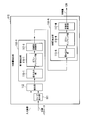
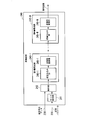
- FIG. 1 It is a block diagram which shows the functional structure of the encoding device 100 which concerns on one Embodiment of this invention. It is a block diagram which shows the functional structure of the feature-value extraction part 110 of the encoding device 100 which concerns on one Embodiment of this invention. It is a block diagram which shows the functional structure of the decoding apparatus 200 which concerns on one Embodiment of this invention. It is a block diagram which shows the functional structure of the reconfiguration
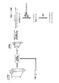
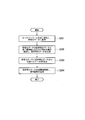
- FIG. 6 is a schematic diagram showing a flow of an encoding process performed by the encoding device 100 according to the embodiment of the present invention.
- 6 is a flowchart showing an operation of the decoding device 200 according to the embodiment of the present invention. It is a schematic diagram which shows the flow of the decoding process by the decoding apparatus 200 which concerns on one Embodiment of this invention.
- FIG. 6 is a schematic diagram showing a flow of a learning process performed by the encoding device 100 and the decoding device 200 according to the embodiment of the present invention.
- Embodiments of the present invention will be described below with reference to the drawings.
- the encoding device 100 that encodes image data and the decoding device 200 that decodes image data will be described.
- the encoding device 100 and the decoding device 200 described below are also applicable to encoding and decoding of data other than image data.
- the configuration of the encoding device 100 will be described below.
- the encoding device 100 receives an input image that is encoding target data and a compression parameter, and outputs a bitstream corresponding to the input image.
- the compression parameter is a parameter for determining a target size of encoded data that is data obtained by encoding an input image.
- FIG. 1 is a block diagram showing a functional configuration of an encoding device 100 according to an embodiment of the present invention.
- the encoding device 100 includes a feature amount extraction unit 110, a quantization unit 120, an encoded data extraction unit 130, and a binarization unit 140.
- the feature amount extraction unit 110 acquires an input image and a compression parameter from an external device.
- the feature amount extraction unit 110 extracts the feature amount of the input image based on the acquired input image and compression parameter.
- the feature amount extraction unit 110 performs feature amount extraction so that the features of the input image are concentrated in a size and a predetermined area based on the compression parameter.
- the predetermined area may be any condition as long as it can be shared by the encoding side and the decoding side.
- the feature amount data may be ordered from the beginning.
- the condition may be transmitted from the encoding side to the decoding side.
- the feature quantity extraction unit 110 outputs information indicating the extracted feature quantity to the quantization unit 120.
- the quantization unit 120 (provisional encoded data acquisition unit) acquires the information output from the feature amount extraction unit 110.
- the quantization unit 120 performs a quantization process on the feature amount based on the acquired information and converts it into temporary coded data (provisional coded data).
- the quantization unit 120 outputs the generated temporary coded data to the coded data extraction unit 130.
- the coded data extraction unit 130 acquires the temporary coded data output from the quantization unit 120. In addition, the encoded data extraction unit 130 acquires the compression parameter from an external device. The encoded data extraction unit 130 extracts encoded data based on the acquired provisional encoded data and compression parameter. The encoded data extraction unit 130 outputs the extracted encoded data to the binarization unit 140.
- the feature amount extraction unit 110 performs feature amount extraction so that the features of the input image are concentrated in the size and area based on the compression parameter.
- the encoded data extraction unit 130 performs processing such that the encoded data has a size based on the compression parameter, for example, a desired bit rate, by deleting the area excluding the area.
- the binarization unit 140 acquires the encoded data output from the encoded data extraction unit 130.
- the binarization unit 140 binarizes the acquired encoded data.
- the binarization unit 140 outputs the binarized encoded data as a bitstream to an external device.
- the feature amount extraction unit 110 is configured to include, for example, a neural network (combination of convolution operation, downsampling, and non-linear conversion) as shown in FIG.
- FIG. 2 is a block diagram showing a functional configuration of the feature quantity extraction unit 110 of the encoding device 100 according to the embodiment of the present invention.
- the feature quantity extraction unit 110 includes a size expansion unit 111, a combination unit 112, and an extraction unit including N layers (first layer extraction unit 113-1 to Nth layer extraction unit 113-N).
- the first layer extraction unit 113-1, ..., And the Nth layer extraction unit 113-N respectively include a convolution unit 115-1, a downsampling unit 116-1, and a non-linear conversion unit.
- the size expansion unit 111 acquires a compression parameter from an external device.
- the size enlargement unit 111 enlarges the obtained compression parameter to the same size as the input image.
- the size expanding unit 111 outputs the expanded compression parameter to the combining unit 112.
- the combining unit 112 acquires an input image from an external device.
- the combining unit 112 also acquires the expanded compression parameter output from the size expansion unit 111.
- the combining unit 112 performs a process of combining the acquired input image and the expanded compression parameter in the channel direction.
- the combining unit 112 outputs the input image combined with the expanded compression parameters to the convolution unit 115-1 of the first layer extraction unit 113-1.
- the convolution unit 115-1 of the first layer extraction unit 113-1 acquires the input image output from the combining unit 112.
- the convolution unit 115-1 performs a convolution process on the acquired input image.
- the convolution unit 115-1 outputs the input image subjected to the convolution processing to the downsampling unit 116-1.
- the downsampling unit 116-1 acquires the input image output from the convolution unit 115-1.
- the downsampling unit 116-1 performs processing of downsampling the acquired input image.
- the downsampling unit 116-1 outputs the downsampled input image to the non-linear conversion unit 117-1.
- the non-linear conversion unit 117-1 acquires the input image output from the down sampling unit 116-1.
- the non-linear conversion unit 117-1 performs a non-linear conversion process on each element of the acquired input image.
- the non-linear conversion unit 117-1 outputs the input image subjected to the non-linear conversion processing to the convolution unit of the extraction unit of the next layer.
- the feature quantity extraction unit 110 extracts the feature quantity of the input image based on the acquired input image and compression parameter.
- the non-linear conversion unit 117-N of the Nth layer extraction unit 113-N outputs information indicating the extracted feature amount to the quantization unit 120.
- the configuration of the decoding device 200 will be described below.
- the decoding device 200 receives the bitstream as an input and outputs a decoded image corresponding to the input image.
- FIG. 3 is a block diagram showing a functional configuration of the decoding device 200 according to the embodiment of the present invention.
- the decoding device 200 includes an inverse binarization unit 210, an encoded data decompression unit 220, a compression parameter calculation unit 230, and a reconstruction unit 240.
- the inverse binarization unit 210 acquires a bitstream from an external device.
- the inverse binarization unit 210 converts the acquired bitstream into encoded data.
- the inverse binarization unit 210 outputs the generated encoded data to the encoded data expansion unit 220 and the compression parameter calculation unit 230, respectively.
- the encoded data decompression unit 220 acquires the encoded data output from the inverse binarization unit 210.
- the encoded data expansion unit 220 expands the number of elements of the acquired encoded data to the same number of elements as the number of elements of the temporary encoded data generated by the quantization unit 120 of the encoding device 100, thereby converting the temporary encoded data.
- the encoded data expansion unit 220 outputs the generated temporary encoded data to the compression parameter calculation unit 230 and the reconstruction unit 240, respectively.
- the compression parameter calculation unit 230 acquires the encoded data output from the inverse binarization unit 210. Further, the compression parameter calculation unit 230 acquires the temporary encoded data output from the encoded data decompression unit 220. The compression parameter calculation unit 230 calculates a compression parameter based on the acquired coded data and temporary coded data. The compression parameter calculation unit 230 outputs the calculated compression parameter to the reconstruction unit 240.
- the reconstruction unit 240 (decoded image acquisition unit) acquires the temporary encoded data output from the encoded data decompression unit 220.
- the reconstruction unit 240 also acquires the compression parameter output from the compression parameter calculation unit 230.
- the reconstruction unit 240 reconstructs the decoded image based on the temporary encoded data and the compression parameter.
- the reconstruction unit 240 outputs the reconstructed decoded image to an external device.
- the reconstruction unit 240 is configured to include, for example, a neural network (combination of deconvolution operation and non-linear conversion) as shown in FIG.
- FIG. 4 is a block diagram showing a functional configuration of the reconstruction unit 240 of the decoding device 200 according to the embodiment of the present invention.
- the reconfiguration unit 240 includes a size enlargement unit 241, a coupling unit 242, and a configuration unit including M layers (first layer configuration unit 243-1 to Mth layer configuration unit 243-M). Composed by.
- the first layer configuration unit 243-1, ..., The Mth layer configuration unit 243-M respectively include a deconvolution unit 245-1 and a non-linear conversion unit 246-1 ,. .., and includes a deconvolution unit 245-M and a non-linear conversion unit 246-M.
- the size enlargement unit 241 acquires the compression parameter output from the compression parameter calculation unit 230.
- the size enlargement unit 241 enlarges the acquired compression parameter to the same size as the input image.
- the size enlarging unit 241 performs a process of enlarging the size to the same size as the input image by adding a predetermined value such as “0”.
- the size expanding unit 241 outputs the expanded compression parameter to the combining unit 242.
- the combining unit 242 acquires the temporary encoded data from the encoded data expansion unit 220. Further, the combining unit 112 acquires the expanded compression parameter output from the size expansion unit 241. The combining unit 242 performs a process of combining the acquired provisionally encoded data and the expanded compression parameter in the channel direction. The combining unit 242 outputs the temporary encoded data combined with the expanded compression parameter to the deconvolution unit 245-1 of the first layer configuration unit 243-1.
- the deconvolution unit 245-1 of the first layer configuration unit 243-1 acquires the temporary encoded data output from the combining unit 242.
- the deconvolution unit 245-1 performs an inverse operation on the convolution operation performed by the feature amount extraction unit 110 of the encoding device 100 on the acquired provisionally encoded data.
- the deconvolution unit 245-1 outputs the inversely calculated temporary encoded data to the non-linear conversion unit 246-1.
- the non-linear conversion unit 246-1 acquires the temporary encoded data output from the deconvolution unit 245-1.
- the non-linear conversion unit 246-1 performs a process of performing non-linear conversion on each element of the acquired provisionally encoded data.
- the non-linear conversion unit 246-1 outputs the temporary coded data subjected to the non-linear conversion processing to the deconvolution unit of the constituent unit of the next layer.
- the reconstruction unit 240 reconstructs a decoded image based on the acquired provisionally encoded data and the compression parameter.
- the non-linear conversion unit 246-M of the Mth layer configuration unit 243-M outputs the reconstructed decoded image to an external device.
- the temporary encoded data transmitted from the encoding device 100 is data indicating only the area where the features of the input image are concentrated.
- the reconstruction unit 240 of the decoding device 200 it is necessary to supplement the area deleted by the encoded data extraction unit 130 of the encoding device 100. Since the area deleted in the encoded data extraction unit 130 is not a feature of the input image, the size enlargement unit 241 of the reconstruction unit 240 of the decoding device 200 has a predetermined value such as “0” as described above. Is added to the temporary encoded data, the reconstruction unit 240 can obtain a decoded image from the temporary encoded data.
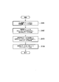
- FIG. 5 is a flowchart showing the operation of the encoding device 100 according to the embodiment of the present invention.
- FIG. 6 is a schematic diagram showing a flow of an encoding process by the encoding device 100 according to the embodiment of the present invention.
- the input image to be encoded is defined as I (x, y, z), and the compression parameter is defined as R.
- x is a variable in the horizontal direction
- y is a variable in the vertical direction
- z is a variable in the channel direction.
- the dimension numbers of x, y, and z are X, Y, and Z, respectively.
- the compression parameter R is a parameter that can determine a desired encoded data size (target size).
- the compression parameter R is assumed to be a parameter indicating a compression rate that can take a value in the range of 0 ⁇ R ⁇ 1.
- the compression ratio is a ratio calculated by the encoded data size / the size of the input image I (x, y, z).
- the feature quantity extraction unit 110 extracts the feature quantity F (x, y, z) by performing a feature quantity extraction process on the input image I (x, y, z) using the compression parameter R as a parameter.
- Step S101 let the number of dimensions of x, y, and z be X ', Y', and Z ', respectively.
- the feature amount extraction processing the above-described neural network as shown in FIG. 2, for example, is used.
- the quantizer 120 transforms the feature quantity F (x, y, z) into a one-dimensional vector in a predetermined order. Then, the quantization unit 120 performs a quantization process such that each element has a predetermined bit precision B ', and generates temporary encoded data (step S102).
- the encoded data extraction unit 130 obtains encoded data by extracting data of the encoded data size calculated from the compression parameter R from the beginning of the provisional encoded data (step S103).
- the binarization unit 140 obtains a bitstream by binarizing the encoded data (step S104).
- FIG. 7 is a flowchart showing the operation of the decoding device 200 according to the embodiment of the present invention.
- FIG. 8 is a schematic diagram showing a flow of a decoding process by the decoding device 200 according to the embodiment of the present invention.
- the inverse binarization unit 210 inversely binarizes the bitstream and converts it into encoded data (step S201).
- the encoded data decompression unit 220 decompresses the encoded data until the number of elements is the same as the number of elements of the temporary encoded data of the encoding device 100, and generates the temporary encoded data (conversion feature amount). Specifically, the encoded data decompression unit 220 (conversion unit) adds a predetermined value (for example, 0 as shown in FIG. 8) to the encoded data by the number of missing elements. (Step S202).
- the reconstruction unit 240 shapes the provisionally encoded data into the input size of the reconstruction process. Then, the reconstruction unit 240 generates a decoded image I ′ (x, y, z) by performing a reconstruction process using the compression parameter R as a parameter on the temporary encoded data (step S204).
- the reconstruction processing the above-mentioned neural network as shown in FIG. 4, for example, is used.
- the entropy coding may be performed on the binarized bit stream (coded data).
- rate control can be performed by feeding back the code amount after entropy coding. For example, when an image is divided into blocks, a certain block is coded at a rate ratio of 0.5 (50%), and the result of entropy coding is 0.4, for example, the code of the next block In encoding, the entire rate control can be performed by encoding with a rate ratio of 0.6, for example.
- the neural network is an auto encoder, and learning is performed so as to obtain a decoded image that is determined to be the same image as the input image.
- the learning in the feature amount extraction unit 110 and the learning in the reconstruction unit 240 are performed at the same time.
- the bit stream for the input image I (x, y, z) is obtained by the encoding process by the encoding device 100 described above.
- a decoded image is obtained from the bitstream by the above-described decoding processing by the decoding device 200.
- the loss value loss is calculated using the loss function defined by the following equation (1).
- diff (a, b) is a function (for example, squared error) for measuring the distance between a and b.
- loss function defined by the above equation (1) is an example, and only some errors may be calculated or different error terms may be added.
- the parameter of the feature quantity extraction unit 110 and the parameter of the reconstruction unit 240 are updated by the backward error propagation method or the like. Learning in the neural network that configures the feature quantity extraction unit 110 and the reconstruction unit 240 by setting the above-described series of flow as one time and repeating a certain number of times for a plurality of sample data or until the loss value loss converges. Is done.
- the encoding device 100 and the decoding device 200 perform the feature amount extraction process and the reconstruction process using the compression parameter as a parameter. Further, the encoding device 100 and the decoding device 200 extract only the data of the encoded data size (the data range corresponding to the target size) required from the beginning at the time of learning, and extract the other data (other than the data range corresponding to the target size). Data range) is filled with a predetermined value (for example, 0) and then decoded.
- the encoding device 100 and the decoding device 200 when the image is compressed (reduced in dimension), the parameters expressing the main features of the image have desired data in the compressed data. Learning is performed so as to be dense (that is, to include more features that determine an image) in a range (for example, elements of the required encoded data size from the beginning of encoded data).
- the encoding device 100 and the decoding device 200 according to the embodiment of the present invention one system can achieve the same effect as when the auto encoder system is individually designed with a plurality of encoded data sizes. You can Further, unlike the conventional technique 1, the encoding / decoding process is not performed many times, and the overhead is not required unlike the conventional technique 2. As a result, according to the encoding device 100 and the decoding device 200 according to the embodiment of the present invention, it is possible to compress data to a desired size while suppressing an increase in processing time and a decrease in encoding efficiency.
- a part or all of the encoding device 100 and the decoding device 200 in the above-described embodiments may be realized by a computer.
- the program for realizing this function may be recorded in a computer-readable recording medium, and the program recorded in this recording medium may be read by a computer system and executed.
- the “computer system” mentioned here includes an OS and hardware such as peripheral devices.
- the “computer-readable recording medium” refers to a portable medium such as a flexible disk, a magneto-optical disk, a ROM, a CD-ROM, or a storage device such as a hard disk built in a computer system.
- the "computer-readable recording medium” means to hold a program dynamically for a short time like a communication line when transmitting the program through a network such as the Internet or a communication line such as a telephone line.
- a volatile memory inside a computer system that serves as a server or a client in that case may hold a program for a certain period of time.
- the program may be for realizing a part of the functions described above, and may be a program that can realize the functions described above in combination with a program already recorded in a computer system, It may be realized by using hardware such as PLD (Programmable Logic Device) and FPGA (Field Programmable Gate Array).
- Encoding Device 110 Feature Extracting Unit 111 Size Enlarging Unit 112 Combining Unit 115-1 to 115-N Convolution Unit 116-1 to 116-N Downsampling Unit 117-1 to 117-N Non-Linear Transform Unit 120 Quantization Unit 130 Encoded data extraction unit 140 Binarization unit 200 Decoding device 210 Inverse binarization unit 220 Encoded data decompression unit 230 Compression parameter calculation unit 240 Reconstruction unit 241 Size expansion unit 242 Coupling unit 245-1 to 245-M Deconvolution Section 246-1 to 246-M Non-linear conversion section
Landscapes
- Engineering & Computer Science (AREA)
- Physics & Mathematics (AREA)
- Theoretical Computer Science (AREA)
- General Physics & Mathematics (AREA)
- Evolutionary Computation (AREA)
- Artificial Intelligence (AREA)
- General Health & Medical Sciences (AREA)
- Mathematical Physics (AREA)
- Data Mining & Analysis (AREA)
- Biophysics (AREA)
- Biomedical Technology (AREA)
- Molecular Biology (AREA)
- Computing Systems (AREA)
- General Engineering & Computer Science (AREA)
- Life Sciences & Earth Sciences (AREA)
- Computational Linguistics (AREA)
- Software Systems (AREA)
- Health & Medical Sciences (AREA)
- Multimedia (AREA)
- Signal Processing (AREA)
- Geometry (AREA)
- Computer Vision & Pattern Recognition (AREA)
- Compression Or Coding Systems Of Tv Signals (AREA)
Abstract
入力された画像を符号化する符号化装置は、前記画像と、前記画像が符号化されたデータである符号化データの目標サイズを決定するためのパラメータとに基づいて、前記目標サイズより大きいサイズの暫定符号化データを得る暫定符号化データ取得部と、前記暫定符号化データにおいて、前記目標サイズに相当するデータ範囲以外のデータ範囲のデータを所定の値に変換することにより前記符号化データを得る符号化データ取得部と、を備え、前記暫定符号化データ取得部は、前記目標サイズに相当するデータ範囲以外のデータ範囲よりも、前記目標サイズに相当するデータ範囲に、前記画像を決定づける特徴をより多く含むように前記暫定符号化データを得る。
Description
本発明は、符号化装置、復号装置、符号化システム、学習方法、及びプログラムに関する。
本願は、2018年11月14日に、日本に出願された特願2018-213791号に基づき優先権を主張し、その内容をここに援用する。
本願は、2018年11月14日に、日本に出願された特願2018-213791号に基づき優先権を主張し、その内容をここに援用する。
画像等の符号化対象データを符号化する方法の一つとして、オートエンコーダ(自己符号化器)を利用した方法がある。オートエンコーダは、入力データから特徴量を得るエンコーダと、特徴量から入力データと近しいデータを得るデコーダからなる。エンコーダ及びデコーダは、任意の演算器によって構築される。例えば入力データが画像である場合、エンコーダは畳み込み演算を行う複数の演算器及び非線形変換器の組み合わせによって構成され、デコーダはエンコーダによる畳み込み演算に対する逆演算を行う複数の演算器及び非線形変換器の組み合わせによって構築される。
一般的に、オートエンコーダを含むニューラルネットワークを用いてシステムの設計を行う場合、ニューラルネットワークの構成(例えば、階層数、ユニット数、活性化関数の種類、及び出力サイズ等)を事前に決定する必要がある。例えば、サイズがX×Y×Zであり、1画素のビット精度がBビットである画像データを入力としたオートエンコーダを設計する場合を考える。ここで、X,Y,及びZは、それぞれ画像の幅、高さ、及びチャネル数を示す。そして、エンコーダの出力サイズをX’×Y’×Z’、及び1要素のビット精度をB’ビットに決定した場合、符号化データサイズ及び圧縮率が一意に定まり、符号化データサイズはX’×Y’×Z’×B’、及び圧縮率は(X’×Y’×Z’×B’)/(X×Y×Z×B)によって表される。このことから、オートエンコーダによる符号化器は、1つのニューラルネットワークに対して1つの符号化データサイズ及び圧縮率でしか符号化することができない。そのため、任意の圧縮サイズで符号化するためには、複数の符号化データサイズに対して、それぞれニューラルネットワークを設計する必要がある。
しかしながら、複数のニューラルネットワークをそれぞれ設計して運用することは、メモリ容量やシステム実装等の観点から実用的でない。これに対し、いくつかの手法が提案されている。例えば、非特許文献1に記載の技術は、入力画像をオートエンコーダに入力して、出力された復号画像と入力画像との差分画像を計算し、その差分画像を再びオートエンコーダに入力して復号差分画像を得る。そして、当該技術は、上記の処理を必要な符号化データサイズになるまで繰り返し行う。これにより、当該技術は、設計されたニューラルネットワークにおける符号化データサイズの倍数となる符号化データサイズで、符号化データサイズを制御する。また、例えば、非特許文献2に記載の技術は、符号化データとは別に、エンコーダ出力の要素ごとに割り当てる符号量(量子化精度)を表した符号量マップを生成する。そして、当該技術は、生成された符号化マップを符号化データとともに伝送することで符号量を制御する。
G.Toderici et al.,"Full Resolution Image Compression with Recurrent Neural Networks," arXiv, 7 Jul 2017.
M.Li et al., "Learning Convolutional Networks for Content-weighted Image Compression," arXiv, 19 Sep 2017.
しかしながら、非特許文献1に記載の技術は、設計されたニューラルネットワークにおける符号化データサイズの倍数となる符号化データサイズでしか、符号化データサイズを制御することができない。そのため、詳細な制御を行うためには、ニューラルネットワークにおける符号化データサイズを小さく設計する必要がある。この場合、所望の符号化データサイズになるまでに何度もエンコード処理及びデコード処理を行わなければならない。これにより、非特許文献1に記載の技術は、処理時間が増大するという課題がある。また、非特許文献2に記載の技術は、符号量マップが余分なオーバーヘッドになる。これにより、非特許文献2に記載の技術は、符号化データサイズが固定されたニューラルネットワークと比べて、符号化効率が低下するという課題がある。
本発明はこのような状況を鑑みてなされたもので、処理時間の増大及び符号化効率の低下を抑えつつ、データを所望の大きさに圧縮することができる技術の提供を目的としている。
本発明の一態様は、入力された画像を符号化する符号化装置であって、前記画像と、前記画像が符号化されたデータである符号化データの目標サイズを決定するためのパラメータとに基づいて、前記目標サイズより大きいサイズの暫定符号化データを得る暫定符号化データ取得部と、前記暫定符号化データにおいて、前記目標サイズに相当するデータ範囲以外のデータ範囲のデータを所定の値に変換することにより前記符号化データを得る符号化データ取得部と、を備え、前記暫定符号化データ取得部は、前記目標サイズに相当するデータ範囲以外のデータ範囲よりも、前記目標サイズに相当するデータ範囲に、前記画像を決定づける特徴をより多く含むように前記暫定符号化データを得る符号化装置である。
また、本発明の一態様は、上記の符号化装置であって、前記パラメータは、符号量又はレート割合である。
また、本発明の一態様は、上記の符号化装置であって、前記符号化データ取得部は、前記暫定符号化データにおいて、前記目標サイズに相当するデータ範囲以外のデータ範囲のデータを削除し、前記データの削除がなされたデータを、復号する対象である前記符号化データとする。
また、本発明の一態様は、前記第1画像と、前記第1画像が符号化されたデータである符号化データの目標サイズを決定するためのパラメータとに基づいて、前記目標サイズより大きいサイズであり、かつ、前記目標サイズに相当するデータ範囲以外のデータ範囲よりも前記目標サイズに相当するデータ範囲に前記第1画像を決定づける特徴をより多く含む暫定符号化データを取得し、前記暫定符号化データにおいて、前記目標サイズに相当するデータ範囲以外のデータ範囲のデータを所定の値に変換することにより前記符号化データを得る前記符号化装置によって符号化された前記符号化データを復号する復号装置であって、前記符号化データと前記パラメータとに基づいて、前記第1画像とは異なる第2画像に対応する符号化データから復号画像を得る復号画像取得部を備える復号装置である。
また、本発明の一態様は、画像と、前記画像が符号化されたデータである符号化データの目標サイズを決定するためのパラメータと、に基づく特徴量であって、前記目標サイズより大きいサイズ、かつ、前記目標サイズに相当するデータ範囲以外のデータ範囲よりも前記目標サイズに相当するデータ範囲に前記画像を決定づける特徴をより多く含むように前記特徴量の抽出を学習する特徴量抽出学習部と、前記特徴量において、前記目標サイズに相当するデータ範囲以外のデータ範囲のデータを所定の値に変換することにより変換特徴量を得る変換部と、前記変換特徴量と前記パラメータとに基づいて、前記画像と同一の画像であると判定される復号画像を得るように前記画像の再構成を学習する復号学習部と、を有する符号化システムである。
また、本発明の一態様は、入力された符号化対象データを符号化する符号化装置であって、前記符号化対象データと、前記符号化対象データが符号化されたデータである符号化データの目標サイズを決定するためのパラメータとに基づいて、前記目標サイズより大きいサイズの暫定符号化データを得る暫定符号化データ取得部と、前記暫定符号化データにおいて、前記目標サイズに相当するデータ範囲以外のデータ範囲のデータを所定の値に変換することにより前記符号化データを得る符号化データ取得部と、を備え、前記暫定符号化データ取得部は、前記目標サイズに相当するデータ範囲以外のデータ範囲よりも、前記目標サイズに相当するデータ範囲に、前記符号化対象データを決定づける特徴をより多く含むように前記暫定符号化データを得る符号化装置である。
また、本発明の一態様は、前記画像が符号化されたデータである符号化データの目標サイズを決定するためのパラメータと、に基づく特徴量において、前記目標サイズより大きいサイズ、かつ、前記目標サイズに相当するデータ範囲以外のデータ範囲よりも前記目標サイズに相当するデータ範囲に前記画像を決定づける特徴をより多く含むように前記特徴量の抽出を学習するステップと、前記特徴量において、前記目標サイズに相当するデータ範囲以外のデータ範囲のデータを所定の値に変換することにより変換特徴量を得るステップと、前記変換特徴量と前記パラメータとに基づいて、前記画像と同一の画像であると判定される復号画像を得るように前記画像の再構成を学習するステップと、を有する学習方法である。
また、本発明の一態様は、上記の符号化装置、又は上記の復号装置としてコンピュータを機能させるためのプログラムである。
本発明により、処理時間の増大及び符号化効率の低下を抑えつつ、データを所望の大きさに圧縮することができる。
<実施形態>
以下、本発明の実施形態について、図面を参照しながら説明する。以下では、一例として、画像データを符号化する符号化装置100、及び、画像データを復号する復号装置200について説明する。但し、以下に説明する符号化装置100及び復号装置200は、画像データ以外のデータに対する符号化及び復号にも適用可能である。
以下、本発明の実施形態について、図面を参照しながら説明する。以下では、一例として、画像データを符号化する符号化装置100、及び、画像データを復号する復号装置200について説明する。但し、以下に説明する符号化装置100及び復号装置200は、画像データ以外のデータに対する符号化及び復号にも適用可能である。
[符号化装置100の構成]
以下、符号化装置100の構成について説明する。符号化装置100は、符号化対象データである入力画像と圧縮パラメータとを入力として、入力画像に対応するビットストリームを出力する。圧縮パラメータとは、入力画像が符号化されたデータである符号化データの目標サイズを決定するためのパラメータである。
以下、符号化装置100の構成について説明する。符号化装置100は、符号化対象データである入力画像と圧縮パラメータとを入力として、入力画像に対応するビットストリームを出力する。圧縮パラメータとは、入力画像が符号化されたデータである符号化データの目標サイズを決定するためのパラメータである。
図1は、本発明の一実施形態に係る符号化装置100の機能構成を示すブロック図である。図1に示すように、符号化装置100は、特徴量抽出部110と、量子化部120と、符号化データ抽出部130と、二値化部140とを含んで構成される。
特徴量抽出部110は、外部の装置から入力画像と圧縮パラメータとを取得する。特徴量抽出部110は、取得された入力画像と圧縮パラメータとに基づいて入力画像の特徴量を抽出する。ここで、特徴量抽出部110は、圧縮パラメータに基づいた大きさ及び所定の領域に、入力画像の特徴が集中するように特徴量抽出を行う。所定の領域とは、符号化側と復号側で共有できる条件であれば何でもよい。例えば、特徴量データの先頭から順でもよい。条件を符号化側から復号側に伝送してもよい。特徴量抽出部110は、抽出された特徴量を示す情報を量子化部120へ出力する。
量子化部120(暫定符号化データ取得部)は、特徴量抽出部110から出力された情報を取得する。量子化部120は、取得された情報に基づく特徴量に対して量子化処理を実行し、仮符号化データ(暫定符号化データ)に変換する。量子化部120は、生成された仮符号化データを符号化データ抽出部130へ出力する。
符号化データ抽出部130(符号化データ取得部)は、量子化部120から出力された仮符号化データを取得する。また、符号化データ抽出部130は、外部の装置から圧縮パラメータを取得する。符号化データ抽出部130は、取得された仮符号化データと圧縮パラメータとに基づいて、符号化データを抽出する。符号化データ抽出部130は、抽出された符号化データを二値化部140へ出力する。
上述したように、特徴量抽出部110は、圧縮パラメータに基づいた大きさ及び領域に、入力画像の特徴が集中するように特徴量抽出を行う。符号化データ抽出部130で、例えば該領域を除く領域を削除することで、符号化データが圧縮パラメータに基づくサイズ、例えば所望のビットレートになるような処理を行う。
二値化部140は、符号化データ抽出部130から出力された符号化データを取得する。二値化部140は、取得された符号化データを二値化する。二値化部140は、二値化された符号化データをビットストリームとして外部の装置へ出力する。
[特徴量抽出部110の構成]
以下、特徴量抽出部110の構成についてさらに詳しく説明する。特徴量抽出部110は、例えば図2に示すようなニューラルネットワーク(畳み込み演算、ダウンサンプリング、及び非線形変換の組み合わせ)を含んで構成される。
以下、特徴量抽出部110の構成についてさらに詳しく説明する。特徴量抽出部110は、例えば図2に示すようなニューラルネットワーク(畳み込み演算、ダウンサンプリング、及び非線形変換の組み合わせ)を含んで構成される。
図2は、本発明の一実施形態に係る符号化装置100の特徴量抽出部110の機能構成を示すブロック図である。図2に示すように、特徴量抽出部110は、サイズ拡大部111と、結合部112と、N層からなる抽出部(第1層抽出部113-1~第N層抽出部113-N)とによって構成される。また、図2に示すように、第1層抽出部113-1、・・・、第N層抽出部113-Nは、それぞれ、畳み込み部115-1とダウンサンプリング部116-1と非線形変換部117-1、・・・、畳み込み部115-Nとダウンサンプリング部116-Nと非線形変換部117-Nによって構成される。
サイズ拡大部111は、外部の装置から圧縮パラメータを取得する。サイズ拡大部111は、取得された圧縮パラメータを、入力画像と同じサイズにまで拡大する処理を行う。サイズ拡大部111は、拡大された圧縮パラメータを結合部112へ出力する。
結合部112は、外部の装置から入力画像を取得する。また、結合部112は、サイズ拡大部111から出力された、拡大された圧縮パラメータを取得する。結合部112は、取得された入力画像と拡大された圧縮パラメータとをチャンネル方向に結合する処理を行う。結合部112は、拡大された圧縮パラメータが結合された入力画像を第1層抽出部113-1の畳み込み部115-1へ出力する。
第1層抽出部113-1の畳み込み部115-1は、結合部112から出力された入力画像を取得する。畳み込み部115-1は、取得された入力画像に対して畳み込み処理を行う。畳み込み部115-1は、畳み込み処理がなされた入力画像をダウンサンプリング部116-1へ出力する。
ダウンサンプリング部116-1は、畳み込み部115-1から出力された入力画像を取得する。ダウンサンプリング部116-1は、取得された入力画像をダウンサンプリングする処理を行う。ダウンサンプリング部116-1は、ダウンサンプリングされた入力画像を非線形変換部117-1へ出力する。
非線形変換部117-1は、ダウンサンプリング部116-1から出力された入力画像を取得する。非線形変換部117-1は、取得された入力画像の各要素に対して非線形変換する処理を行う。非線形変換部117-1は、非線形変換処理がなされた入力画像を、次の層の抽出部の畳み込み部へ出力する。
上記の処理を第1層から第N層まで繰り返すことにより、特徴量抽出部110は、取得された入力画像と圧縮パラメータとに基づいて入力画像の特徴量を抽出する。第N層抽出部113-Nの非線形変換部117-Nは、抽出された特徴量を示す情報を量子化部120へ出力する。
[復号装置200の構成]
以下、復号装置200の構成について説明する。復号装置200は、ビットストリームを入力として、入力画像に対応する復号画像を出力する。
以下、復号装置200の構成について説明する。復号装置200は、ビットストリームを入力として、入力画像に対応する復号画像を出力する。
図3は、本発明の一実施形態に係る復号装置200の機能構成を示すブロック図である。図3に示すように、復号装置200は、逆二値化部210と、符号化データ伸張部220と、圧縮パラメータ算出部230と、再構成部240とを含んで構成される。
逆二値化部210は、外部の装置からビットストリームを取得する。逆二値化部210は、取得されたビットストリームを符号化データに変換する。逆二値化部210は、生成された符号化データを、符号化データ伸張部220及び圧縮パラメータ算出部230へそれぞれ出力する。
符号化データ伸張部220は、逆二値化部210から出力された符号化データを取得する。符号化データ伸張部220は、取得された符号化データの要素数を、符号化装置100の量子化部120によって生成される仮符号化データと同じ要素数まで伸張することにより仮符号化データを生成する。符号化データ伸張部220は、生成された仮符号化データを、圧縮パラメータ算出部230及び再構成部240へそれぞれ出力する。
圧縮パラメータ算出部230は、逆二値化部210から出力された符号化データを取得する。また、圧縮パラメータ算出部230は、符号化データ伸張部220から出力された仮符号化データを取得する。圧縮パラメータ算出部230は、取得された符号化データと仮符号化データとに基づいて圧縮パラメータを算出する。圧縮パラメータ算出部230は、算出された圧縮パラメータを再構成部240へ出力する。
再構成部240(復号画像取得部)は、符号化データ伸張部220から出力された仮符号化データを取得する。また、再構成部240は、圧縮パラメータ算出部230から出力された圧縮パラメータを取得する。再構成部240は、仮符号化データと圧縮パラメータとに基づいて復号画像を再構成する。再構成部240は、再構成された復号画像を外部の装置へ出力する。
[再構成部240の構成]
以下、再構成部240の構成についてさらに詳しく説明する。再構成部240は、例えば図4に示すようなニューラルネットワーク(逆畳み込み演算及び非線形変換の組み合わせ)を含んで構成される。
以下、再構成部240の構成についてさらに詳しく説明する。再構成部240は、例えば図4に示すようなニューラルネットワーク(逆畳み込み演算及び非線形変換の組み合わせ)を含んで構成される。
図4は、本発明の一実施形態に係る復号装置200の再構成部240の機能構成を示すブロック図である。図4に示すように、再構成部240は、サイズ拡大部241と、結合部242と、M層からなる構成部(第1層構成部243-1~第M層構成部243-M)とによって構成される。また、図4に示すように、第1層構成部243-1、・・・、第M層構成部243-Mは、それぞれ、逆畳み込み部245-1と非線形変換部246-1、・・・、逆畳み込み部245-Mと非線形変換部246-Mとによって構成される。
サイズ拡大部241は、圧縮パラメータ算出部230から出力された圧縮パラメータを取得する。サイズ拡大部241は、取得された圧縮パラメータを、入力画像と同じサイズにまで拡大する処理を行う。サイズ拡大部241は、予め定められた「0」等の値を付与することで、入力画像と同じサイズにまで拡大する処理を行う。サイズ拡大部241は、拡大された圧縮パラメータを結合部242へ出力する。
結合部242は、符号化データ伸張部220から仮符号化データを取得する。また、結合部112は、サイズ拡大部241から出力された、拡大された圧縮パラメータを取得する。結合部242は、取得された仮符号化データと拡大された圧縮パラメータとをチャンネル方向に結合する処理を行う。結合部242は、拡大された圧縮パラメータが結合された仮符号化データを第1層構成部243-1の逆畳み込み部245-1へ出力する。
第1層構成部243-1の逆畳み込み部245-1は、結合部242から出力された仮符号化データを取得する。逆畳み込み部245-1は、取得された仮符号化データに対して、符号化装置100の特徴量抽出部110による畳み込み演算に対する逆演算を行う。逆畳み込み部245-1は、逆演算された仮符号化データを非線形変換部246-1へ出力する。
非線形変換部246-1は、逆畳み込み部245-1から出力された仮符号化データを取得する。非線形変換部246-1は、取得された仮符号化データの各要素に対して非線形変換する処理を行う。非線形変換部246-1は、非線形変換処理がなされた仮符号化データを、次の層の構成部の逆畳み込み部へ出力する。
上記の処理を第1層から第M層まで繰り返すことにより、再構成部240は、取得された仮符号化データと圧縮パラメータとに基づいて復号画像を再構成する。第M層構成部243-Mの非線形変換部246-Mは、再構成された復号画像を外部の装置へ出力する。
上述したように、符号化装置100から送信される仮符号化データは、入力画像の特徴が集中している領域のみを示すデータである。言い換えると、復号装置200の再構成部240により復号画像を得るためには、符号化装置100の符号化データ抽出部130により削除された領域を補う必要がある。符号化データ抽出部130において削除された領域は入力画像の特徴ではないため、復号装置200の再構成部240のサイズ拡大部241は、上述したように、予め定められた「0」等の値を仮符号化データに付与することで、再構成部240が仮符号化データから復号画像を得られることができる。
[符号化装置100の動作]
以下、符号化装置100の動作について、具体例を挙げて説明する。
図5は、本発明の一実施形態に係る符号化装置100の動作を示すフローチャートである。また、図6は、本発明の一実施形態に係る符号化装置100による符号化処理の流れを示す模式図である。
以下、符号化装置100の動作について、具体例を挙げて説明する。
図5は、本発明の一実施形態に係る符号化装置100の動作を示すフローチャートである。また、図6は、本発明の一実施形態に係る符号化装置100による符号化処理の流れを示す模式図である。
まず、符号化対象の入力画像をI(x,y,z)、及び圧縮パラメータをRとして定義する。ここで、xは水平方向の変数、yは垂直方向の変数、及びzはチャンネル方向の変数を示す。また、x,y,zの次元数をそれぞれX,Y,Zとする。また、1要素のビット精度をBビットとする。例えば、入力画像I(x,y,z)がグレー画像である場合にはZ=1であり、入力画像I(x,y,z)がRGB画像である場合にはZ=3である。また、圧縮パラメータRは、所望の符号化データサイズ(目標サイズ)を決定することができるパラメータである。本実施形態では、一例として、圧縮パラメータRは、0<R≦1の範囲の値を取りうる、圧縮率を示すパラメータであるものとする。なお、圧縮率とは、符号化データサイズ/入力画像I(x,y,z)のサイズ、によって算出される比率である。
特徴量抽出部110は、入力画像I(x,y,z)に対して、圧縮パラメータRをパラメータとする特徴量抽出処理を行うことにより、特徴量F(x,y,z)を抽出する(ステップS101)。ここで、x,y,zの次元数をそれぞれX’,Y’,Z’とする。特徴量抽出処理としては、上述した、例えば図2に示すようなニューラルネットワークが用いられる。
量子化部120は、特徴量F(x,y,z)を、所定の順序で1次元のベクトルに変形する。そして、量子化部120は、各要素が所定のビット精度B’となるように量子化処理を行い、仮符号化データを生成する(ステップS102)。
符号化データ抽出部130は、仮符号化データの先頭から、圧縮パラメータRから計算される符号化データサイズ分のデータを抽出することにより、符号化データを得る(ステップS103)。
二値化部140は、符号化データを二値化することにより、ビットストリームを得る(ステップS104)。
[復号装置200の動作]
以下、復号装置200の動作について、具体例を挙げて説明する。
図7は、本発明の一実施形態に係る復号装置200の動作を示すフローチャートである。また、図8は、本発明の一実施形態に係る復号装置200による復号処理の流れを示す模式図である。
以下、復号装置200の動作について、具体例を挙げて説明する。
図7は、本発明の一実施形態に係る復号装置200の動作を示すフローチャートである。また、図8は、本発明の一実施形態に係る復号装置200による復号処理の流れを示す模式図である。
逆二値化部210は、ビットストリームを逆二値化し、符号化データに変換する(ステップS201)。
符号化データ伸張部220は、符号化データを符号化装置100の仮符号化データと同じ要素数になるまで伸張し、仮符号化データ(変換特徴量)を生成する。具体的には、符号化データ伸張部220(変換部)は、符号化データに対して、不足している要素数の分だけ所定の値(図8に示すように、例えば0)を追加する(ステップS202)。
符号化データ伸張部220は、符号化データを符号化装置100の仮符号化データと同じ要素数になるまで伸張し、仮符号化データ(変換特徴量)を生成する。具体的には、符号化データ伸張部220(変換部)は、符号化データに対して、不足している要素数の分だけ所定の値(図8に示すように、例えば0)を追加する(ステップS202)。
圧縮パラメータ算出部230は、符号化データと仮符号化データとに基づいて、圧縮パラメータRを算出する。具体的には、圧縮パラメータ算出部230は、符号化データに対応する復号画像のデータサイズ(すなわち、X×Y×Z×B)を算出する。そして、圧縮パラメータ算出部230は、圧縮パラメータRを、R=(X’×Y’×Z’×B’)/(X×Y×Z×B)として算出する(ステップS203)。
再構成部240は、仮符号化データを再構成処理の入力サイズに整形する。そして、再構成部240は、仮符号化データに対して、圧縮パラメータRをパラメータとする再構成処理を行うことにより、復号画像I’(x,y,z)を生成する(ステップS204)。再構成処理としては、上述した、例えば図4に示すようなニューラルネットワークが用いられる。
なお、特徴量の次元数は、X×Y×Z×B=X’×Y’×Z’×B’を満たすように設計されることが最善である。しかしながら、これは必須条件ではなく、例えば、X×Y×Z×B>X’×Y’×Z’×B’として設計されてもよい。但し、その場合には、入力できる圧縮パラメータRの最大値に上限が付く。
なお、二値化されたビットストリーム(符号化データ)に対してエントロピー符号化を行う構成にしてもよい。この場合、エントロピー符号化後の符号量がフィードバックされることによって、レート制御を行うことが可能になる。例えば、画像をブロックに分割して、あるブロックをレート割合0.5(50%)で符号化し、エントロピー符号化した結果が例えば0.4になってしまった場合に、その次のブロックの符号化においてはレート割合を例えば0.6として符号化すること等によって、全体のレート制御を行うことができる。
[学習処理の流れ]
次に、本実施形態における特徴量抽出部110(特徴量抽出学習部)、及び再構成部240(復号学習部)を構成するニューラルネットワークにおける学習方法について説明する。ここで、ニューラルネットワークはオートエンコーダであり、入力画像と同一の画像であると判定される復号画像を得るように学習が行われる。特徴量抽出部110における学習と、再構成部240における学習とは、同時に行われる。
次に、本実施形態における特徴量抽出部110(特徴量抽出学習部)、及び再構成部240(復号学習部)を構成するニューラルネットワークにおける学習方法について説明する。ここで、ニューラルネットワークはオートエンコーダであり、入力画像と同一の画像であると判定される復号画像を得るように学習が行われる。特徴量抽出部110における学習と、再構成部240における学習とは、同時に行われる。
学習処理の事前準備として、入力画像I(x,y,z)及び圧縮パラメータRのセットをサンプルデータとするデータセットを用意する。圧縮パラメータRは、その取りうる値から一様分布のランダム値とする。まず、上述した符号化装置100による符号化処理によって、入力画像I(x,y,z)に対するビットストリームを得る。そして、そのビットストリームから、上述した復号装置200による復号処理によって復号画像を得る。次に、下記の式(1)によって定義される損失関数を用いて損失値lossを算出する。
loss=ΣxΣyΣzdiff(I(x,y,z),I’(x,y,z))
・・・(1)
・・・(1)
ここで、diff(a,b)は、aとbとの距離を測る関数(例えば二乗誤差など)である。なお、上記の式(1)で定義される損失関数は一例であり、一部の誤差のみを算出したり、異なる誤差項を追加したりしてもよい。
算出された損失値lossを用いて、逆誤差伝播法などにより、特徴量抽出部110のパラメータ、及び再構成部240のパラメータを更新する。上記の一連の流れを1回とし、複数のサンプルデータで一定回数、あるいは、損失値lossが収束するまで繰り返されることによって、特徴量抽出部110、及び再構成部240を構成するニューラルネットワークにおける学習が行われる。
以上説明したように、本発明の一実施形態に係る符号化装置100及び復号装置200は、圧縮パラメータをパラメータとして、特徴量抽出処理及び再構成処理を行う。また、符号化装置100及び復号装置200は、学習時に先頭から必要な符号化データサイズ分のデータ(目標サイズに相当するデータ範囲)のみを抽出し、それ以外(目標サイズに相当するデータ範囲以外のデータ範囲)を所定の値(例えば0)で埋めてから復号する。このような構成を備えることにより、符号化装置100及び復号装置200は、画像を圧縮(低次元化)した際に、画像の主な特徴を表現するパラメータが、圧縮されたデータにおける所望のデータ範囲(例えば、符号化データの先頭から必要な符号化データサイズ分の要素)に密集するように(すなわち、画像を決定づける特徴をより多く含むように)学習する。
そのため、本発明の一実施形態に係る符号化装置100及び復号装置200によれば、オートエンコーダシステムを複数の符号化データサイズで個別に設計した時と同じ効果を、1つのシステムで実現することができる。また、従来技術1のように何度もエンコード・デコード処理を行うこともなく、従来技術2のようにオーバーヘッドも必要としない。これにより、本発明の一実施形態に係る符号化装置100及び復号装置200によれば、処理時間の増大及び符号化効率の低下を抑えつつ、データを所望の大きさに圧縮することができる。
上述した実施形態における符号化装置100及び復号装置200の一部又は全部を、コンピュータで実現するようにしてもよい。その場合、この機能を実現するためのプログラムをコンピュータ読み取り可能な記録媒体に記録して、この記録媒体に記録されたプログラムをコンピュータシステムに読み込ませ、実行することによって実現してもよい。なお、ここでいう「コンピュータシステム」とは、OSや周辺機器等のハードウェアを含むものとする。また、「コンピュータ読み取り可能な記録媒体」とは、フレキシブルディスク、光磁気ディスク、ROM、CD-ROM等の可搬媒体、コンピュータシステムに内蔵されるハードディスク等の記憶装置のことをいう。さらに「コンピュータ読み取り可能な記録媒体」とは、インターネット等のネットワークや電話回線等の通信回線を介してプログラムを送信する場合の通信線のように、短時間の間、動的にプログラムを保持するもの、その場合のサーバやクライアントとなるコンピュータシステム内部の揮発性メモリのように、一定時間プログラムを保持しているものも含んでもよい。また上記プログラムは、上述した機能の一部を実現するためのものであっても良く、さらに上述した機能をコンピュータシステムにすでに記録されているプログラムとの組み合わせで実現できるものであってもよく、PLD(Programmable Logic Device)やFPGA(Field Programmable Gate Array)等のハードウェアを用いて実現されるものであってもよい。
以上、図面を参照して本発明の実施形態を説明してきたが、上記実施形態は本発明の例示に過ぎず、本発明が上記実施形態に限定されるものではないことは明らかである。したがって、本発明の技術思想及び要旨を逸脱しない範囲で構成要素の追加、省略、置換、及びその他の変更を行ってもよい。
100 符号化装置
110 特徴量抽出部
111 サイズ拡大部
112 結合部
115-1~115-N 畳み込み部
116-1~116-N ダウンサンプリング部
117-1~117-N 非線形変換部
120 量子化部
130 符号化データ抽出部
140 二値化部
200 復号装置
210 逆二値化部
220 符号化データ伸張部
230 圧縮パラメータ算出部
240 再構成部
241 サイズ拡大部
242 結合部
245-1~245-M 逆畳み込み部
246-1~246-M 非線形変換部
110 特徴量抽出部
111 サイズ拡大部
112 結合部
115-1~115-N 畳み込み部
116-1~116-N ダウンサンプリング部
117-1~117-N 非線形変換部
120 量子化部
130 符号化データ抽出部
140 二値化部
200 復号装置
210 逆二値化部
220 符号化データ伸張部
230 圧縮パラメータ算出部
240 再構成部
241 サイズ拡大部
242 結合部
245-1~245-M 逆畳み込み部
246-1~246-M 非線形変換部
Claims (8)
- 入力された画像を符号化する符号化装置であって、
前記画像と、前記画像が符号化されたデータである符号化データの目標サイズを決定するためのパラメータとに基づいて、前記目標サイズより大きいサイズの暫定符号化データを得る暫定符号化データ取得部と、
前記暫定符号化データにおいて、前記目標サイズに相当するデータ範囲以外のデータ範囲のデータを所定の値に変換することにより前記符号化データを得る符号化データ取得部と、
を備え、
前記暫定符号化データ取得部は、前記目標サイズに相当するデータ範囲以外のデータ範囲よりも、前記目標サイズに相当するデータ範囲に、前記画像を決定づける特徴をより多く含むように前記暫定符号化データを得る
符号化装置。 - 前記パラメータの値は、符号量又はレート割合である
請求項1に記載の符号化装置。 - 前記符号化データ取得部は、
前記暫定符号化データにおいて、前記目標サイズに相当するデータ範囲以外のデータ範囲のデータを削除し、前記データの削除がなされたデータを、復号する対象である前記符号化データとする
請求項1又は請求項2に記載の符号化装置。 - 第1画像と、前記第1画像が符号化されたデータである符号化データの目標サイズを決定するためのパラメータとに基づいて、前記目標サイズより大きいサイズであり、かつ、前記目標サイズに相当するデータ範囲以外のデータ範囲よりも前記目標サイズに相当するデータ範囲に前記第1画像を決定づける特徴をより多く含む暫定符号化データを取得し、前記暫定符号化データにおいて、前記目標サイズに相当するデータ範囲以外のデータ範囲のデータを所定の値に変換することにより前記符号化データを得る符号化装置によって符号化された前記符号化データを復号する復号装置であって、
前記符号化データと前記パラメータとに基づいて、前記第1画像とは異なる第2画像に対応する符号化データから復号画像を得る復号画像取得部
を備える復号装置。 - 画像と、前記画像が符号化されたデータである符号化データの目標サイズを決定するためのパラメータと、に基づく特徴量であって、前記目標サイズより大きいサイズ、かつ、前記目標サイズに相当するデータ範囲以外のデータ範囲よりも前記目標サイズに相当するデータ範囲に前記画像を決定づける特徴をより多く含むように前記特徴量の抽出を学習する特徴量抽出学習部と、
前記特徴量において、前記目標サイズに相当するデータ範囲以外のデータ範囲のデータを所定の値に変換することにより変換特徴量を得る変換部と、
前記変換特徴量と前記パラメータとに基づいて、前記画像と同一の画像であると判定される復号画像を得るように前記画像の再構成を学習する復号学習部と、
を有する符号化システム。 - 入力された符号化対象データを符号化する符号化装置であって、
前記符号化対象データと、前記符号化対象データが符号化されたデータである符号化データの目標サイズを決定するためのパラメータとに基づいて、前記目標サイズより大きいサイズの暫定符号化データを得る暫定符号化データ取得部と、
前記暫定符号化データにおいて、前記目標サイズに相当するデータ範囲以外のデータ範囲のデータを所定の値に変換することにより前記符号化データを得る符号化データ取得部と、
を備え、
前記暫定符号化データ取得部は、前記目標サイズに相当するデータ範囲以外のデータ範囲よりも、前記目標サイズに相当するデータ範囲に、前記符号化対象データを決定づける特徴をより多く含むように前記暫定符号化データを得る
符号化装置。 - 画像と、前記画像が符号化されたデータである符号化データの目標サイズを決定するためのパラメータと、に基づく特徴量において、前記目標サイズより大きいサイズ、かつ、前記目標サイズに相当するデータ範囲以外のデータ範囲よりも前記目標サイズに相当するデータ範囲に前記画像を決定づける特徴をより多く含むように前記特徴量の抽出を学習するステップと、
前記特徴量において、前記目標サイズに相当するデータ範囲以外のデータ範囲のデータを所定の値に変換することにより変換特徴量を得るステップと、
前記変換特徴量と前記パラメータとに基づいて、前記画像と同一の画像であると判定される復号画像を得るように前記画像の再構成を学習するステップと、
を有する学習方法。 - 請求項1、2、3又は6に記載の符号化装置、又は請求項4に記載の復号装置としてコンピュータを機能させるためのプログラム。
Priority Applications (2)
| Application Number | Priority Date | Filing Date | Title |
|---|---|---|---|
| JP2020556667A JP7041380B2 (ja) | 2018-11-14 | 2019-09-24 | 符号化システム、学習方法、及びプログラム |
| US17/292,617 US20220005233A1 (en) | 2018-11-14 | 2019-09-24 | Encoding apparatus, decoding apparatus, encoding system, learning method and program |
Applications Claiming Priority (2)
| Application Number | Priority Date | Filing Date | Title |
|---|---|---|---|
| JP2018-213791 | 2018-11-14 | ||
| JP2018213791 | 2018-11-14 |
Publications (1)
| Publication Number | Publication Date |
|---|---|
| WO2020100435A1 true WO2020100435A1 (ja) | 2020-05-22 |
Family
ID=70730694
Family Applications (1)
| Application Number | Title | Priority Date | Filing Date |
|---|---|---|---|
| PCT/JP2019/037254 Ceased WO2020100435A1 (ja) | 2018-11-14 | 2019-09-24 | 符号化装置、復号装置、符号化システム、学習方法、及びプログラム |
Country Status (3)
| Country | Link |
|---|---|
| US (1) | US20220005233A1 (ja) |
| JP (1) | JP7041380B2 (ja) |
| WO (1) | WO2020100435A1 (ja) |
Cited By (1)
| Publication number | Priority date | Publication date | Assignee | Title |
|---|---|---|---|---|
| JP2023526180A (ja) * | 2021-04-19 | 2023-06-21 | テンセント・アメリカ・エルエルシー | 滑らかな品質制御による適応ニューラル画像圧縮のための代替の入力最適化 |
Families Citing this family (3)
| Publication number | Priority date | Publication date | Assignee | Title |
|---|---|---|---|---|
| US11700518B2 (en) * | 2019-05-31 | 2023-07-11 | Huawei Technologies Co., Ltd. | Methods and systems for relaying feature-driven communications |
| US11595847B2 (en) * | 2019-12-19 | 2023-02-28 | Qualcomm Incorporated | Configuration of artificial intelligence (AI) modules and compression ratios for user-equipment (UE) feedback |
| US20240056575A1 (en) * | 2020-12-22 | 2024-02-15 | Intellectual Discovery Co., Ltd. | Deep learning-based image coding method and device |
Citations (2)
| Publication number | Priority date | Publication date | Assignee | Title |
|---|---|---|---|---|
| JPH09149420A (ja) * | 1995-11-27 | 1997-06-06 | Graphics Commun Lab:Kk | 動画像圧縮方法および装置 |
| US20180173994A1 (en) * | 2016-12-15 | 2018-06-21 | WaveOne Inc. | Enhanced coding efficiency with progressive representation |
Family Cites Families (10)
| Publication number | Priority date | Publication date | Assignee | Title |
|---|---|---|---|---|
| US7106909B2 (en) * | 2001-12-25 | 2006-09-12 | Canon Kabushiki Kaisha | Method and apparatus for encoding image data in accordance with a target data size |
| JP4693603B2 (ja) * | 2004-11-15 | 2011-06-01 | キヤノン株式会社 | 画像符号化装置及びその制御方法、並びに、コンピュータプログラム及びコンピュータ可読記憶媒体 |
| JP4732203B2 (ja) * | 2006-03-17 | 2011-07-27 | キヤノン株式会社 | 画像符号化装置及び復号装置及びそれらの制御方法、並びに、コンピュータプログラム及びコンピュータ可読記憶媒体 |
| JP5684488B2 (ja) * | 2009-04-20 | 2015-03-11 | 富士フイルム株式会社 | 画像処理装置、画像処理方法およびプログラム |
| GB2516422A (en) * | 2013-07-09 | 2015-01-28 | Sony Corp | Data encoding and decoding |
| GB2516425B (en) * | 2013-07-17 | 2015-12-30 | Gurulogic Microsystems Oy | Encoder and decoder, and method of operation |
| GB2523347B (en) * | 2014-02-20 | 2016-01-13 | Gurulogic Microsystems Oy | Encoder, decoder and method |
| KR102099626B1 (ko) * | 2014-08-20 | 2020-04-10 | 한국전자통신연구원 | 부호화 장치 및 방법 |
| JP6512928B2 (ja) * | 2015-04-28 | 2019-05-15 | キヤノン株式会社 | 画像符号化装置、画像処理装置、画像符号化方法 |
| JP6626295B2 (ja) * | 2015-09-09 | 2019-12-25 | キヤノン株式会社 | 画像符号化装置、画像処理装置、画像符号化方法 |
-
2019
- 2019-09-24 US US17/292,617 patent/US20220005233A1/en not_active Abandoned
- 2019-09-24 WO PCT/JP2019/037254 patent/WO2020100435A1/ja not_active Ceased
- 2019-09-24 JP JP2020556667A patent/JP7041380B2/ja active Active
Patent Citations (2)
| Publication number | Priority date | Publication date | Assignee | Title |
|---|---|---|---|---|
| JPH09149420A (ja) * | 1995-11-27 | 1997-06-06 | Graphics Commun Lab:Kk | 動画像圧縮方法および装置 |
| US20180173994A1 (en) * | 2016-12-15 | 2018-06-21 | WaveOne Inc. | Enhanced coding efficiency with progressive representation |
Non-Patent Citations (3)
| Title |
|---|
| KAI, HAN ET AL.: "AUTOENCODER INSPIRED UNSUPERVISED FEATURE SELECTION", ARXIV:1710.08310V3, 9 April 2018 (2018-04-09), pages 1 - 5, XP033401574 * |
| MU, LI ET AL.: "Learning Convolutional Networks for Content-weighted Image Compression", ARXIV:1703.10553V2, 19 September 2017 (2017-09-19), pages 1 - 11, XP080753253 * |
| NICK, JOHNSTON ET AL.: "Improved Lossy Image Compression with Priming and Spatially Adaptive Bit Rates for Recurrent Networks", ARXIV:1703.10114V1, 29 March 2017 (2017-03-29), pages 1 - 9, XP080752976 * |
Cited By (3)
| Publication number | Priority date | Publication date | Assignee | Title |
|---|---|---|---|---|
| JP2023526180A (ja) * | 2021-04-19 | 2023-06-21 | テンセント・アメリカ・エルエルシー | 滑らかな品質制御による適応ニューラル画像圧縮のための代替の入力最適化 |
| JP7471733B2 (ja) | 2021-04-19 | 2024-04-22 | テンセント・アメリカ・エルエルシー | 滑らかな品質制御による適応ニューラル画像圧縮のための代替の入力最適化 |
| US12159438B2 (en) | 2021-04-19 | 2024-12-03 | Tencent America LLC | Substitutional input optimization for adaptive neural image compression with smooth quality control |
Also Published As
| Publication number | Publication date |
|---|---|
| US20220005233A1 (en) | 2022-01-06 |
| JPWO2020100435A1 (ja) | 2021-09-02 |
| JP7041380B2 (ja) | 2022-03-24 |
Similar Documents
| Publication | Publication Date | Title |
|---|---|---|
| CN114631320B (zh) | 对图像执行人工智能ai编码和ai解码的设备和方法 | |
| JP7041380B2 (ja) | 符号化システム、学習方法、及びプログラム | |
| RU2417518C2 (ru) | Эффективное кодирование и декодирование блоков преобразования | |
| TW201826786A (zh) | 用於視訊寫碼之低複雜度符號預測 | |
| US9661321B2 (en) | Remote viewing of large image files | |
| CN110383695A (zh) | 用于对数字图像或视频流进行编码和解码的方法和装置 | |
| JP2026502079A (ja) | 画像を符号化及び復号するための方法及びデバイス | |
| JP2020527884A (ja) | デジタルデータ圧縮のための方法及びデバイス | |
| Chawla et al. | Image compression techniques: a review | |
| US20060067582A1 (en) | Progressive JPEG decoding system | |
| Mahmud | An improved data compression method for general data | |
| RU2683614C2 (ru) | Кодер, декодер и способ работы с использованием интерполяции | |
| Bandyopadhyay et al. | Image compression using approximate matching and run length | |
| JP7141007B2 (ja) | 符号化装置、符号化方法及びプログラム | |
| US11516515B2 (en) | Image processing apparatus, image processing method and image processing program | |
| WO2019225344A1 (ja) | 符号化装置、画像補間システム及び符号化プログラム | |
| CN101980464B (zh) | 数据编码方法、解码方法、编码器和解码器 | |
| Shah et al. | Software implementation of CCSDS recommended hyperspectral lossless image compression | |
| US20170201759A1 (en) | Method and device for image encoding and image decoding | |
| Nazar et al. | Implementation of JPEG-LS compression algorithm for real time applications | |
| US10003808B2 (en) | Apparatus and method for encoding | |
| Shaikh et al. | Huffman coding technique for image compression | |
| JP2006033161A (ja) | 符号化処理装置 | |
| Nandi et al. | Fractal image compression by using loss-less encoding on the parameters of affine transforms | |
| Paikrao et al. | Verification of Role of Data Scanning Direction in Image Compression using Fuzzy Composition Operations |
Legal Events
| Date | Code | Title | Description |
|---|---|---|---|
| 121 | Ep: the epo has been informed by wipo that ep was designated in this application |
Ref document number: 19885717 Country of ref document: EP Kind code of ref document: A1 |
|
| ENP | Entry into the national phase |
Ref document number: 2020556667 Country of ref document: JP Kind code of ref document: A |
|
| NENP | Non-entry into the national phase |
Ref country code: DE |
|
| 122 | Ep: pct application non-entry in european phase |
Ref document number: 19885717 Country of ref document: EP Kind code of ref document: A1 |