WO2020098538A1 - 一种用于电励磁双凸极电机的转矩控制方法 - Google Patents
一种用于电励磁双凸极电机的转矩控制方法 Download PDFInfo
- Publication number
- WO2020098538A1 WO2020098538A1 PCT/CN2019/115897 CN2019115897W WO2020098538A1 WO 2020098538 A1 WO2020098538 A1 WO 2020098538A1 CN 2019115897 W CN2019115897 W CN 2019115897W WO 2020098538 A1 WO2020098538 A1 WO 2020098538A1
- Authority
- WO
- WIPO (PCT)
- Prior art keywords
- torque
- control
- phase
- error
- err
- Prior art date
- Legal status (The legal status is an assumption and is not a legal conclusion. Google has not performed a legal analysis and makes no representation as to the accuracy of the status listed.)
- Ceased
Links
Images




Classifications
-
- H—ELECTRICITY
- H02—GENERATION; CONVERSION OR DISTRIBUTION OF ELECTRIC POWER
- H02P—CONTROL OR REGULATION OF ELECTRIC MOTORS, ELECTRIC GENERATORS OR DYNAMO-ELECTRIC CONVERTERS; CONTROLLING TRANSFORMERS, REACTORS OR CHOKE COILS
- H02P23/00—Arrangements or methods for the control of AC motors characterised by a control method other than vector control
- H02P23/04—Arrangements or methods for the control of AC motors characterised by a control method other than vector control specially adapted for damping motor oscillations, e.g. for reducing hunting
-
- H—ELECTRICITY
- H02—GENERATION; CONVERSION OR DISTRIBUTION OF ELECTRIC POWER
- H02P—CONTROL OR REGULATION OF ELECTRIC MOTORS, ELECTRIC GENERATORS OR DYNAMO-ELECTRIC CONVERTERS; CONTROLLING TRANSFORMERS, REACTORS OR CHOKE COILS
- H02P23/00—Arrangements or methods for the control of AC motors characterised by a control method other than vector control
- H02P23/30—Direct torque control [DTC] or field acceleration method [FAM]
-
- H—ELECTRICITY
- H02—GENERATION; CONVERSION OR DISTRIBUTION OF ELECTRIC POWER
- H02P—CONTROL OR REGULATION OF ELECTRIC MOTORS, ELECTRIC GENERATORS OR DYNAMO-ELECTRIC CONVERTERS; CONTROLLING TRANSFORMERS, REACTORS OR CHOKE COILS
- H02P27/00—Arrangements or methods for the control of AC motors characterised by the kind of supply voltage
- H02P27/04—Arrangements or methods for the control of AC motors characterised by the kind of supply voltage using variable-frequency supply voltage, e.g. inverter or converter supply voltage
- H02P27/06—Arrangements or methods for the control of AC motors characterised by the kind of supply voltage using variable-frequency supply voltage, e.g. inverter or converter supply voltage using DC to AC converters or inverters
- H02P27/08—Arrangements or methods for the control of AC motors characterised by the kind of supply voltage using variable-frequency supply voltage, e.g. inverter or converter supply voltage using DC to AC converters or inverters with pulse width modulation
Definitions
- the invention relates to the technical field of variable reluctance motor control, in particular to a torque control method for an electric excitation double salient pole motor.
- the electric excitation double-salient pole motor is a more commonly used reluctance motor structure. There are no windings and magnetic steel on the motor rotor, so its structure is simple and strong, easy to maintain, and has high reliability. It has a good application prospect in the fields of aircraft start / power generation system, wind power generation system, new energy vehicles, etc.
- a reluctance motor due to the structure of the double-salient pole of the fixed rotor of the electric excitation double-salient pole motor, it has the problems of large torque ripple, large noise and severe vibration, which limits its promotion and application to a certain extent.
- the research direction of the optimization of the torque performance of the electric excitation double salient pole motor is mainly divided into two categories: one is to reduce the torque ripple by optimizing the design of the electric excitation double salient pole motor body; the other is to combine the electric excitation
- the electromagnetic characteristics of the double-salient pole motor, a new motor angle control strategy is proposed, and to a certain extent, the torque ripple of the electric excitation double-salient pole motor is reduced, and the torque performance of the motor is improved.
- Angle control strategy is based on the standard angle control strategy, according to a certain rule of each switch tube in advance or lag to open, turn off and reverse control strategy.
- the existing angle control strategy is still a current closed-loop control strategy, that is, indirectly controlling the torque of the motor by controlling the waveform of the current.
- the torque of the motor will still have a large torque ripple.
- Embodiments of the present invention provide a torque control method for an electric excitation doubly salient pole motor, which can suppress torque ripple and improve the torque performance of the electric excitation doubly salient pole motor.
- the control structure of double closed loop of speed and torque is adopted, and the speed and torque are used as the controlled variable, and the drive signal of the power converter is used as the controlled variable.
- the control principle is roughly: the output of the speed outer ring is used as the given value of the motor torque, and the torque observer outputs the corresponding torque value according to the collected three-phase current signal and the rotor position signal as the torque feedback value, The feedback value of torque is fed back to perform closed-loop control of torque.
- Figure 1 is a block diagram of a speed regulation system of an electric excitation double salient pole motor using a direct torque control method
- Figure 2 is a block diagram of direct torque control of an electric excitation double salient pole motor
- Figure 3 is an inductance characteristic diagram of an electric excitation double salient pole motor
- Fig. 6 is the torque simulation result of the direct torque control method of the electric excitation double salient pole motor
- FIG. 7 is a schematic diagram of a method flow provided by an embodiment of the present invention.
- An embodiment of the present invention provides a torque control method for an electric excitation double-salient-pole motor.
- the purpose of this embodiment is to control the operation of the power converter in real time to achieve closed-loop control of torque.
- the control structure of double closed loop of speed and torque is adopted, and the speed and torque are used as the controlled variable, and the drive signal of the power converter is used as the controlled variable.
- the control principle is: the output of the speed outer loop is used as the given value of the motor torque, and the torque observer outputs the corresponding torque value according to the collected three-phase current signal and the rotor position signal, as the torque feedback value, will Torque feedback value feedback, closed-loop control of torque.
- the method includes:
- Step 101 Obtain the analog signals i a , i b and i c collected by the current Hall sensor, and the rotor position signal ⁇ of the electric excitation doubly salient motor, and transmit them to the torque observer.
- the current Hall sensor collects the analog signals i a , i b , and i c of the three-phase current, and the corresponding capital letters are usually used in the electrical field to indicate the mode.
- electrical signal conversion such embodiments can I a, I B and I C correspond to an analog signal i a, i b and a digital signal i c respectively converted through a series of the present embodiment.
- the current Hall sensor refers to the three circles at the starting points of the three lines i a , i b and i c of the input of the current detection link in FIG. 1. Generally, this circle can be used to represent the current Hall sensor.
- the torque observer obtains the torque feedback value T e and outputs it.
- the rotor position signal ⁇ of the electric excitation double salient pole motor is specifically collected by the resolver and its rotary decoder (usually referring to the decoder chip corresponding to the resolver), for example: the resolver obtains a correlation with the rotor position angle Analog signal (a sine and cosine signal with amplitude and position angle as a function), the decoding chip converts the analog signal into a digital signal of the rotor position angle that can be recognized by the DSP and other controllers, here the resolver and its rotary decoder
- the existing originals can be used, and the installation and collection method can also use the existing collection scheme, which is not repeated in this embodiment.
- the purpose of this embodiment here is only to use the collected rotor position signal ⁇ of the electrically excited doubly salient pole motor.
- the torque observer link in this embodiment can be understood as: the torque observer is an offline three-dimensional look-up table T ( ⁇ , i p ) stored in the memory of the microprocessor (DSP2812), where ⁇ is the rotor position angle, i p For the phase winding current, p represents any phase of A, B, and C.
- the torque observer is based on a large amount of finite element simulation data and a look-up table constructed by linear interpolation.
- the torque observer When the direct torque control system of the electric excitation double salient pole motor is running, the torque observer will use the analog signals i a , i b and i c collected by the current Hall sensor and the rotor position signal output by the resolver and its decoder ⁇ , output the corresponding torque feedback value T e as the torque feedback value.
- Step 102 the output of the speed outer ring is used as the torque setpoint of the electric excitation doubly salient motor T e * , and the torque setpoint T e * is subtracted from the torque feedback value T e ,
- the torque control error of the electric excitation double salient pole motor is T e_err .
- the speed outer loop in this embodiment can be understood as: the rotor position signal is collected by the resolver and its decoder, the speed feedback value n is obtained through the speed calculation link, the speed given value n * is different from the feedback value, and the speed is adjusted
- the output value T e * of the converter is used as the given value of torque.
- the rotation speed calculation link is also a section of program code stored in the DSP for calculating the rotation speed.
- Step 103 the control error of the input torque T e_err control link to the hysteresis, the hysteresis control according to the link control error torque T e_err size, the lookup table outputs switch state control error signal ⁇ T.
- the hysteresis control link in this embodiment can be understood as a control method executed by program code, for example, the hysteresis control link is a piece of code stored in a DSP (digital signal processor, digital signal processor).
- the given value T e * of the torque is different from the feedback value T e , and the control error of the obtained torque is T e_err , which is used as the input of the hysteresis control link.
- the switch state look-up table combines the error control signal ⁇ T and the rotor position signal ⁇ to output a drive signal PWM to the power converter.
- the switch state look-up table in this embodiment is also a piece of program code stored in the DSP.
- the logic process of the switch state look-up table link can be understood as: the switch state look-up table is based on the torque formula and inductance characteristics of the electrically excited doubly salient motor Designed. Among them, the torque formula is:
- T p is the single-phase total torque output
- T pr is the single-phase reluctance torque
- T pe is the single-phase excitation torque
- L p is the phase winding self-inductance
- i f is the excitation current
- L pf is the excitation
- the winding and the phase winding have mutual inductance
- ⁇ represents the rotor position angle
- p is any one of the three phases A, B, and C of the electric excitation doubly salient pole motor.
- the self-inductance of the phase winding of the electric excitation double salient pole motor and the mutual inductance of the excitation winding and the phase winding are a function of the rotor position angle, which is the inductance characteristic of the electric excitation double salient pole motor, as shown in FIG. 3.
- the excitation current flows from the power supply to the excitation winding as the positive direction of the excitation current, and vice versa as the reverse direction of the excitation current.
- the direction of the excitation current as a positive direction and the rotation direction of the rotor as a positive direction as an example, when 0 ⁇ 120 °, positive current flows through phase A, and negative current flows through phase B, and the motor generates positive torque; negative current flows through phase A. With positive current flowing through phase B, the motor will produce negative torque.
- T band is the ring width of torque hysteresis control
- the link keeps the error control signal output at the last moment
- the switch state look-up table maintains the drive signal output at the previous moment.
- the power converter in this embodiment can be understood as: the switch state look-up table combines the torque error control signal ⁇ T and the rotor position angle ⁇ to control the work of the power converter in real time by outputting the drive signal to realize the electric excitation of the double salient pole motor Closed-loop control of torque.
- the research direction of the optimization of the torque performance of the electric excitation double salient pole motor is mainly divided into two categories: one is to reduce the torque ripple by optimizing the design of the electric excitation double salient pole motor body; the other is to combine the electric excitation
- a new motor control strategy is proposed for the electromagnetic characteristics of double-salient pole motors to reduce torque ripple.
- the control strategies of electric excitation double salient pole motors that have been proposed so far are: 1. Standard angle control strategy; 2. Advance angle control strategy; 3. Three-phase six-state control strategy; 4. Three-phase nine-state control strategy; 5. Asymmetric Current control strategy.
- the standard angle control strategy is the simplest control method for the electric excitation double salient pole motor.
- This method controls the opening and closing of each phase switch tube based on the inductive characteristics of the electric excitation double salient pole motor.
- the standard angle control strategy can produce a large torque when the motor is running at low speed, but there is a large torque ripple when running at high speed.
- the latter four control strategies all add angle control parameters, so they can be collectively referred to as angle control strategies.
- the above angle control strategies have reduced the torque ripple of the electric excitation double salient pole motor to a certain extent and improved the torque performance of the motor.
- the present invention aims to propose a direct torque control method for an electric excitation doubly salient motor, thereby improving the torque performance of the motor.
- This embodiment specifically discloses a direct torque control method for an electric excitation double salient pole motor, which adopts a speed-torque double closed-loop control structure, which takes the speed and torque as the controlled variable, and the controlled variable is the drive signal of the power converter .
- the control principle is: the output of the speed outer ring is used as the given value of the torque, and the torque observer outputs the corresponding torque value according to the collected three-phase current signal and the rotor position signal, as the torque feedback value, the torque The given value and feedback value are output through the hysteresis control and the switch state look-up table to output the corresponding power converter drive signal.
- the invention avoids the torque ripple problem caused by directly controlling the phase current and indirectly controlling the torque in the current closed-loop control.
- the invention directly controls the torque of the electric excitation double-salient pole motor, so the torque ripple can be effectively suppressed and the torque performance of the electric excitation double-salient pole motor can be improved.
- the torque observer includes: an offline three-dimensional look-up table T ( ⁇ , i p ) stored in the memory of the microprocessor (DSP2812), where ⁇ is the rotor position angle and i p is the phase
- the winding current, p represents any one of the three phases A, B, and C of the electrically excited doubly salient motor.
- the torque observer is based on a large amount of finite element simulation data and a look-up table constructed by linear interpolation.
- the speed outer loop is essentially a logic calculation process, which includes: the rotor position signal ⁇ is output by the resolver and its decoder; the speed feedback value, the speed given value and the feedback value are obtained through the speed calculation link Make a difference; the output value T e * after the speed PI regulator is used as the given value of torque.
- the speed calculation link outputs the feedback value of the speed; the given value of the speed can be set manually and stored in advance; the torque observer outputs the torque feedback value; the speed regulator outputs the torque Desired point.
- the speed regulator is essentially the PI adjustment link of the speed; the output of the speed PI adjustment should be a physical quantity that can change the speed; from the mechanical motion equation: T e is the electromagnetic torque of the motor, T L is the load torque; T 0 is the no-load torque; J is the rotational inertia, ⁇ is the angular velocity, and ⁇ has a linear relationship with the rotation speed. It can be seen from this formula that the torque can directly change the speed, so the output value of the speed outer loop is the torque given value.
- the step 103 according to the control error torque T e_err size of the lookup table outputs an error control signal to the switch ⁇ T state, comprising:
- T band is the ring width of torque hysteresis control.
- the hysteresis control link maintains the error control signal output at the previous moment among them, Is the error control signal output by the hysteresis control link at the current k time, It is the error control signal output by the hysteresis control link at the previous time.
- the switch state look-up table is set based on the torque formula and inductance characteristics of the electric excitation doubly salient motor, and the torque formula includes:
- T p is the single-phase total torque output
- T pr is the single-phase reluctance torque
- T pe is the single-phase excitation torque
- L p is the phase winding self-inductance
- i f is the excitation current
- L pf is the excitation
- the winding and the phase winding have mutual inductance
- ⁇ represents the rotor position angle
- p is any one of the three phases A, B, and C of the electric excitation doubly salient pole motor.
- the self-inductance of the phase winding of the electric excitation double salient pole motor and the mutual inductance of the excitation winding and the phase winding are a function of the rotor position angle, which is the inductance characteristic of the electric excitation double salient pole motor.
- the direction of the excitation current as the positive direction and the rotation direction of the rotor as the positive direction as an example
- the positive current flows in the A phase and the negative current flows in the B phase, and the motor generates positive torque.
- Negative current flows through phase A and positive current flows through phase B, and the motor generates negative torque.
- the excitation current flows from the power supply to the excitation winding as the positive direction of the excitation current, and vice versa as the reverse direction of the excitation current
- the counterclockwise rotation of the rotor is defined as the positive direction, and vice versa.
- Figure 1 is a block diagram of the speed regulation system of an electric excitation double salient pole motor using a direct torque control method, in which:
- a rotary transformer and its decoder are used to collect the rotor position signal ⁇ , the rotor position angle signal is sent to the microprocessor, and the motor speed is calculated by a pre-programmed microprocessor program;
- Three current Hall sensors are used to collect three-phase current analog signals i a , i b , and i c respectively .
- the three-phase current analog signal is converted into a voltage signal by a sampling resistor, after a second-order low pass
- the source filter filters out high-frequency noise signals, and then sends them to the A / D conversion chip to convert the analog signals into digital signals I A , I B , and I C.
- the sampling frequency of the current signal A / D conversion is f s , and then A
- the digital signal output by the / D conversion chip is sent to the microprocessor;
- the torque feedback value is output by the torque observer in combination with the three-phase current signal and the rotor position signal.
- the torque observer is based on a large amount of finite element simulation data, constructed using linear interpolation, and stored in the microprocessor (DSP2812) memory offline three-dimensional lookup table T ( ⁇ , i p ).
- ⁇ is the rotor position angle
- i p is the phase winding current
- p represents any phase of A, B, and C.
- T band is the ring width of the torque hysteresis control
- the error control signal output by the hysteresis control link is low, that is If T e_err ⁇ T band , the error control signal output by the hysteresis control link is high, that is If -T band ⁇ T e_err ⁇ T band , the hysteresis control link maintains the error control signal output at the previous moment among them, Is the error control signal output by the hysteresis control link at the current k time, It is the error control signal output by the hysteresis control link at the previous time;
- Switching state lookup table define the excitation current flowing from the power supply to the excitation winding as the positive direction of the excitation current, otherwise the reverse direction of the excitation current, and define the counterclockwise rotation of the rotor as the positive direction and vice versa.
- T band is the torque hysteresis loop Control loop width
- each set of control logic contains six kinds of drive signals of the power converter.
- the four sets of control logic are shown in Table 1.
- Power converter uses a three-phase full-bridge inverter circuit, as shown in Figure 1.
- Q1 ⁇ Q6 are metal-oxide field-effect transistors (Metal-Oxide-Semiconductor Field-Effect Transistor, MOSFET), D1 ⁇ D6 are their parasitic anti-parallel diodes.
- MOSFET Metal-Oxide-Semiconductor Field-Effect Transistor
- D1 ⁇ D6 are their parasitic anti-parallel diodes.
- the drive signal output from the switch state look-up table controls the conduction mode of the power converters Q1 to Q6, thereby realizing closed-loop control of torque.
- Figure 2 is a block diagram of the direct torque control of an electric excitation double salient pole motor.
- the control block diagram shown in Figure 2 mainly includes the following links: speed feedback link, speed adjustment link, torque feedback link, torque adjustment link, switch state look-up table, power converter and electric excitation double salient pole motor.
- the speed feedback link includes the resolver and its decoder and the speed calculation link;
- the speed adjustment link is the speed PI regulator;
- the torque feedback link consists of a current Hall sensor that collects three-phase current signals, a rotary transformer that collects rotor position signals, and It consists of a decoder and a torque observer;
- the torque regulation link is a torque hysteresis control link;
- the power converter is a three-phase full-bridge inverter.
- FIG 3 is a doubly salient pole electric motor inductance characteristic diagram, FIG. L af, L bf, L cf respectively, the mutual inductance between the A, B, C-phase winding and a field winding, L a, L b, L c
- ⁇ in the figure is the rotor position angle. Taking 0 °, 120 ° and 240 ° as the demarcation points, the change of inductance in an electrical cycle is divided into three intervals, namely the inductance rising area, the inductance falling area, and the inductance unchanged area.
- the cut-off points are the positions where the three-phase stator poles of A, B, and C are aligned with the rotor poles. At this time, the inductance of the corresponding phase is the largest.
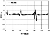
- FIG. 4 is a simulation waveform diagram of the torque observer error proposed by the present invention. The error is obtained by subtracting the simulation result of the torque observer output value from the finite element simulation result of the output torque of the electric excitation doubly salient motor.
- Figure 4 shows that the torque observer of the electric excitation double salient pole motor designed in this case has good accuracy.
- Fig. 5 is a simulation verification diagram of the torque observer error proposed by the patent "Direct Sliding Mode Dual-Salient-Pole Motor Direct Torque Control Device and Method”.
- the error is a finite element of the output torque of the electrically excited double-salient-pole motor
- the simulation result is obtained by subtracting the simulation result of the torque observer output value.
- Figure 5 shows that the torque observer of the electric excitation double-salient-pole motor proposed by the patent "Direct Torque Control Device and Method of Double-Salient-Pole Motor Based on Terminal Sliding Mode” has a large torque observation error.
- Fig. 6 is a torque simulation result diagram of a direct torque control method of an electric excitation double salient pole motor.
- the simulation result of the torque average value is 1.87 N ⁇ m, and the torque ripple rate is 80.14%.
- the torque ripple of the electric excitation double salient pole motor has been significantly reduced, and the torque performance has been improved to a certain extent.
- T ripple rate is the maximum torque in a single electrical cycle
- T min is the minimum torque in a single electrical cycle
- T avg is the average torque in a single electrical cycle.
Landscapes
- Engineering & Computer Science (AREA)
- Power Engineering (AREA)
- Control Of Electric Motors In General (AREA)
Abstract
Description


| 开通 | 关断 | 开通 | 关断 | 开通 | 关断 |

Claims (8)
- 一种用于电励磁双凸极电机的转矩控制方法,其特征在于,包括:步骤101,获取电流霍尔传感器采集的三相电流的模拟信号i a、i b和i c,所述电励磁双凸极电机的转子位置信号θ向所述转矩观测器传输,所述转矩观测器得到转矩反馈值T e并输出;步骤102,将转速外环的输出作为所述电励磁双凸极电机的转矩给定值为T e *,用所述转矩给定值T e *减去所述转矩反馈值T e得到所述电励磁双凸极电机的转矩的控制误差为T e_err;步骤103,将所述转矩的控制误差T e_err输入至滞环控制环节,滞环控制环节根据所述转矩的控制误差T e_err大小,向开关状态查询表输出误差控制信号ε T;步骤104,所述开关状态查询表结合误差控制信号ε T和所述转子位置信号θ,向功率变换器输出驱动信号PWM。
- 根据权利要求1所述的方法,其特征在于,所述转矩观测器包括:存储于微处理器(DSP2812)的内存中的离线三维查找表T(θ,i p),其中,θ为转子位置角,i p为相绕组电流,p代表所述电励磁双凸极电机的A、B、C三相中的任一相。
- 根据权利要求1所述的方法,其特征在于,所述转速外环,包括:获取所述转子位置信号θ,和转速的反馈值,转速给定值与反馈值作差,经过转速调节器的输出值T e *,作为转矩的给定值。
- 根据权利要求1所述的方法,其特征在于,所述步骤103中根据所述转矩的控制误差T e_err大小,向开关状态查询表输出误差控制信号ε T,包括:记录当前为k时刻,若T e_err≤-T band则所述滞环控制环节输出的误差控制信号为低电平,即其中,T band为转矩滞环控制的环宽。

- 根据权利要求4所述的方法,其特征在于,还包括:若T e_err≥T band,则所述滞环控制环节输出的误差控制信号为高电平,即

- 根据权利要求5所述的方法,其特征在于,还包括:若-T band≤T e_err≤T band,则所述滞环控制环节保持上一时刻输出的误差控制信号其中,
 为当前k时刻滞环控制环节输出的误差控制信号,
 为上一时刻滞环控制环节输出的误差控制信号。
- 根据权利要求1或6所述的方法,其特征在于,所述开关状态查询表是基于所述电励磁双凸极电动机的转矩公式与电感特性设置的,所述转矩公式包括:
 其中,T p是单相的总转矩输出,T pr表示单相磁阻转矩,T pe表示单相励磁转矩,L p表示相绕组自感,i f表示励磁电流,L pf表示励磁绕组与相绕组互感,θ表示转子位置角,p所述电励磁双凸极电机的A、B、C三相中的任一相。当0<θ≤120°时,A相通正电流,B相通负电流,电机会产生正转矩;A相通负电流,B相通正电流,电机会产生负转矩。
 - 根据权利要求7所述的方法,其特征在于,当T e_err=T e *-T e≤-T band,所述滞环控制环节输出的误差控制信号所述开关状 态查询表输出的驱动信号使转矩减小,即A相上管Q1与B相下管Q6关断;
 当T e_err=T e *-T e≥T band,所述滞环控制环节输出的误差控制信号所述开关状态查询表输出的驱动信号应使转矩增加,即A相上管Q1与B相下管Q6开通;
 当-T band≤T e_err=T e *-T e≤T band,所述滞环控制环节保持上一时刻输出的误差控制信号则开关状态查询表保持上一时刻输出的驱动信号。
Applications Claiming Priority (2)
| Application Number | Priority Date | Filing Date | Title |
|---|---|---|---|
| CN201811346348.0A CN109450330B (zh) | 2018-11-13 | 2018-11-13 | 一种用于电励磁双凸极电机的转矩控制方法 |
| CN201811346348.0 | 2018-11-13 |
Publications (1)
| Publication Number | Publication Date |
|---|---|
| WO2020098538A1 true WO2020098538A1 (zh) | 2020-05-22 |
Family
ID=65552823
Family Applications (1)
| Application Number | Title | Priority Date | Filing Date |
|---|---|---|---|
| PCT/CN2019/115897 Ceased WO2020098538A1 (zh) | 2018-11-13 | 2019-11-06 | 一种用于电励磁双凸极电机的转矩控制方法 |
Country Status (2)
| Country | Link |
|---|---|
| CN (1) | CN109450330B (zh) |
| WO (1) | WO2020098538A1 (zh) |
Families Citing this family (12)
| Publication number | Priority date | Publication date | Assignee | Title |
|---|---|---|---|---|
| CN109450330B (zh) * | 2018-11-13 | 2021-07-30 | 南京航空航天大学 | 一种用于电励磁双凸极电机的转矩控制方法 |
| CN110429872B (zh) * | 2019-08-29 | 2021-03-16 | 沈阳工业大学 | 一种car-bldcm转矩脉动抑制控制系统及方法 |
| CN110829939B (zh) * | 2019-11-15 | 2021-12-24 | 南京航空航天大学 | 一种降低电励磁双凸极电机转矩脉动的控制方法 |
| CN112332713B (zh) * | 2020-09-18 | 2023-10-27 | 南京航空航天大学 | 一种用于双段式电励磁双凸极电机的转矩分配控制方法 |
| CN114400949B (zh) * | 2021-04-16 | 2023-10-10 | 南京航空航天大学 | 基于开绕组混合励磁双凸极电机的电流塑形控制方法 |
| CN113411014B (zh) * | 2021-07-28 | 2021-12-17 | 南京航空航天大学 | 基于转矩闭环抑制转矩脉动的电励磁双凸极电机控制方法 |
| CN113824359B (zh) * | 2021-09-10 | 2023-07-04 | 南京信息工程大学 | 一种双凸极电机提前角自寻优控制方法及系统 |
| CN113972878B (zh) * | 2021-10-25 | 2023-10-13 | 南京航空航天大学 | 基于迭代自适应控制的电励磁双凸极电机电流控制方法 |
| CN114665771B (zh) * | 2022-05-06 | 2023-04-11 | 西南交通大学 | 一种电励磁双凸极电机转矩脉动抑制方法 |
| CN115133844B (zh) * | 2022-08-09 | 2023-04-28 | 南京航空航天大学 | 一种电励磁双凸极电机失磁故障下的容错电动运行方法 |
| CN115411992B (zh) * | 2022-08-26 | 2026-04-03 | 南京航空航天大学 | 一种双凸极电机最优电流矢量的转矩脉动抑制方法 |
| CN115833697B (zh) * | 2022-12-16 | 2023-07-18 | 南京航空航天大学 | 一种电励磁双凸极发电系统的不对称电流控制方法 |
Citations (5)
| Publication number | Priority date | Publication date | Assignee | Title |
|---|---|---|---|---|
| KR101557579B1 (ko) * | 2014-03-31 | 2015-10-06 | 경성대학교 산학협력단 | Pwm 방식을 이용한 pmsm의 dtc 제어방법 |
| CN105897076A (zh) * | 2016-04-15 | 2016-08-24 | 东南大学 | 基于电压矢量的开关磁阻电机直接瞬时转矩控制方法 |
| CN107425782A (zh) * | 2017-07-12 | 2017-12-01 | 大连理工大学 | 开关磁阻电机实现直接瞬时转矩控制的方法 |
| CN107425783A (zh) * | 2017-08-09 | 2017-12-01 | 江苏上骐集团有限公司 | 一种能减少开关磁阻电机转矩脉动的方法 |
| CN109450330A (zh) * | 2018-11-13 | 2019-03-08 | 南京航空航天大学 | 一种用于电励磁双凸极电机的转矩控制方法 |
Family Cites Families (3)
| Publication number | Priority date | Publication date | Assignee | Title |
|---|---|---|---|---|
| WO1998042070A1 (fr) * | 1997-03-19 | 1998-09-24 | Hitachi, Ltd. | Appareil et procede de commande de moteur a induction |
| CN101393699B (zh) * | 2008-10-17 | 2010-12-01 | 南京航空航天大学 | 双凸极电机的风轮机模拟器及其控制方法 |
| CN108683378A (zh) * | 2018-06-07 | 2018-10-19 | 张家港首驱动力科技有限公司 | 一种利用电机电控系统来对发动机转矩波动补偿的方法 |
-
2018
- 2018-11-13 CN CN201811346348.0A patent/CN109450330B/zh active Active
-
2019
- 2019-11-06 WO PCT/CN2019/115897 patent/WO2020098538A1/zh not_active Ceased
Patent Citations (5)
| Publication number | Priority date | Publication date | Assignee | Title |
|---|---|---|---|---|
| KR101557579B1 (ko) * | 2014-03-31 | 2015-10-06 | 경성대학교 산학협력단 | Pwm 방식을 이용한 pmsm의 dtc 제어방법 |
| CN105897076A (zh) * | 2016-04-15 | 2016-08-24 | 东南大学 | 基于电压矢量的开关磁阻电机直接瞬时转矩控制方法 |
| CN107425782A (zh) * | 2017-07-12 | 2017-12-01 | 大连理工大学 | 开关磁阻电机实现直接瞬时转矩控制的方法 |
| CN107425783A (zh) * | 2017-08-09 | 2017-12-01 | 江苏上骐集团有限公司 | 一种能减少开关磁阻电机转矩脉动的方法 |
| CN109450330A (zh) * | 2018-11-13 | 2019-03-08 | 南京航空航天大学 | 一种用于电励磁双凸极电机的转矩控制方法 |
Also Published As
| Publication number | Publication date |
|---|---|
| CN109450330A (zh) | 2019-03-08 |
| CN109450330B (zh) | 2021-07-30 |
Similar Documents
| Publication | Publication Date | Title |
|---|---|---|
| WO2020098538A1 (zh) | 一种用于电励磁双凸极电机的转矩控制方法 | |
| CN102710206B (zh) | 一种变速永磁交流发电机系统及其双端口稳压控制方法 | |
| CN110829939A (zh) | 一种降低电励磁双凸极电机转矩脉动的控制方法 | |
| CN111193454B (zh) | 开关磁阻轮毂电机减振及脉动抑制复合控制系统构造方法 | |
| CN110635740A (zh) | 一种基于电压前馈补偿策略的永磁同步电机矢量控制方法 | |
| Chen et al. | Comparative investigation of torque-ripple suppression control strategies based on torque-sharing function for switched reluctance motor | |
| CN105811848B (zh) | 一种开关磁阻电机变增益pi控制方法 | |
| CN114400949B (zh) | 基于开绕组混合励磁双凸极电机的电流塑形控制方法 | |
| CN108540028B (zh) | 一种基于改进型重复控制器的电机电流谐波抑制装置及方法 | |
| CN111431450B (zh) | 一种磁通切换电机转矩脉动抑制控制系统及控制方法 | |
| CN104767447A (zh) | 一种无刷直流电机五段式矢量控制系统 | |
| CN102594254A (zh) | 降低永磁同步电机噪音的系统及控制方法 | |
| CN107294463A (zh) | 轴向电励磁复合转子周向错位磁阻电机控制系统及方法 | |
| CN105790651B (zh) | 一种三相双凸极无刷直流电机的控制方法及其驱动系统 | |
| CN107231109B (zh) | 一种大功率异步电动机低开关频率运行控制方法 | |
| CN104201957B (zh) | 一种基于合成电压矢量技术的异步电机直接转矩控制方法 | |
| CN104716878B (zh) | 三相双凸极无刷直流电机的控制方法和驱动系统 | |
| CN202696533U (zh) | 一种变速永磁交流发电机系统 | |
| CN103391034A (zh) | 电动汽车轮毂用盘式无铁心永磁同步电机控制器及方法 | |
| CN108199625A (zh) | 一种三相九开关开绕组永磁无刷直流电机控制系统及方法 | |
| CN107947659A (zh) | 一种dfig‑dc系统的定子电流正弦化控制方法 | |
| CN204810188U (zh) | 基于模型预测控制的三相感应电机直接转矩控制系统 | |
| CN105629737B (zh) | 一种内燃机车异步电机内模控制方法 | |
| CN101814887B (zh) | 低损耗混合式步进电机驱动控制方法 | |
| CN118300470B (zh) | 一种无感永磁同步电机用控制器的控制系统及方法 |
Legal Events
| Date | Code | Title | Description |
|---|---|---|---|
| 121 | Ep: the epo has been informed by wipo that ep was designated in this application |
Ref document number: 19883879 Country of ref document: EP Kind code of ref document: A1 |
|
| NENP | Non-entry into the national phase |
Ref country code: DE |
|
| 122 | Ep: pct application non-entry in european phase |
Ref document number: 19883879 Country of ref document: EP Kind code of ref document: A1 |
|
| 122 | Ep: pct application non-entry in european phase |
Ref document number: 19883879 Country of ref document: EP Kind code of ref document: A1 |
|
| 32PN | Ep: public notification in the ep bulletin as address of the adressee cannot be established |
Free format text: NOTING OF LOSS OF RIGHTS PURSUANT TO RULE 112(1) EPC (EPO FORM 1205A DATED 30.11.2021) |
|
| 122 | Ep: pct application non-entry in european phase |
Ref document number: 19883879 Country of ref document: EP Kind code of ref document: A1 |