WO2020096051A1 - Self-propelled tree felling/shipping machine - Google Patents
Self-propelled tree felling/shipping machine Download PDFInfo
- Publication number
- WO2020096051A1 WO2020096051A1 PCT/JP2019/043941 JP2019043941W WO2020096051A1 WO 2020096051 A1 WO2020096051 A1 WO 2020096051A1 JP 2019043941 W JP2019043941 W JP 2019043941W WO 2020096051 A1 WO2020096051 A1 WO 2020096051A1
- Authority
- WO
- WIPO (PCT)
- Prior art keywords
- grapple
- felling
- rotating
- self
- rotating frame
- Prior art date
Links
Images


Classifications
-
- A—HUMAN NECESSITIES
- A01—AGRICULTURE; FORESTRY; ANIMAL HUSBANDRY; HUNTING; TRAPPING; FISHING
- A01G—HORTICULTURE; CULTIVATION OF VEGETABLES, FLOWERS, RICE, FRUIT, VINES, HOPS OR SEAWEED; FORESTRY; WATERING
- A01G23/00—Forestry
-
- A—HUMAN NECESSITIES
- A01—AGRICULTURE; FORESTRY; ANIMAL HUSBANDRY; HUNTING; TRAPPING; FISHING
- A01G—HORTICULTURE; CULTIVATION OF VEGETABLES, FLOWERS, RICE, FRUIT, VINES, HOPS OR SEAWEED; FORESTRY; WATERING
- A01G23/00—Forestry
- A01G23/02—Transplanting, uprooting, felling or delimbing trees
- A01G23/08—Felling trees
Definitions
- a swing bracket 39 of the grapple device is rotatably attached to the slide bracket 34 via a rotary bearing 40.
- the grapple bracket 26 is attached to the swing bracket 39 via a lateral pin 41, so that the grapple of the grapple apparatus can swing, for example, 15 ° forward and 15 ° backward.
- This back and forth deflection of the grapples 28, 28 of the grapple device 9 is preferably enabled when moving towards the front position of the grapple device 9, but not possible in the rear position.
- a pair of left and right contact elements 42, 42 provided on the upper surface of the grapple bracket 26 and a contact surface 43, 43 extending forward from the front support plate 13 of the cutter box 12 and contacting the contact elements are provided.
Abstract
Provided is a self-propelled tree felling/shipping machine which is able to move up and down inclined forest land as well as horizontal forest land and to fell and ship large-diameter trees. The self-propelled tree felling/shipping machine is provided with, in an inner space (8) of a travelling body structure (2): a rotating frame (11) including a grapple device (9) having a pair of grapples (28) for grappling and holding a standing tree laterally, and a cutting device (10) including dual blades or a single blade (50) or a chain saw (50') for cutting a standing tree laterally to fell the standing tree; and a device for rotating the rotating frame (11) between a vertical position and a horizontal position of the grapple device and the cutting device. The grapples of the grapple device cause the standing tree to fell through a reverse rotation of the rotating frame. After the felling, the tree felling/shipping machine travels to drag and ship the tree felled by the grapples of the grapple device.
Description
本発明は、立木としての木材を一対のグラップルで横から抱き抱えて保持しながら、カッターで木材を切断し、グラップルを木材の伐倒に追従させ、グラップルを介して伐倒した木材を搬出するようにした自走式木材伐倒搬出機に関する。
The present invention holds a piece of wood as a standing tree by holding it sideways with a pair of grapples, cuts the wood with a cutter, causes the grapple to follow the felling of the wood, and carries out the felled wood through the grapple. The self-propelled timber felling unloader.
木材を伐倒する場合は、ほぼ人手によるチェーソー伐倒が一般的であるため、労務災害による人身事故の発生が起こり易い。人身事故防止のために機械化が望まれるが、大型機械は、林地では身動きが取れず、また勾配角度が45°以上になると、土壌や地盤が悪くなって大型機械の搬入さえできないのが原状である。
When cutting timber, it is common to use a chased saw to cut down wood, so it is easy for a personal injury to occur due to a labor accident. Mechanization is desired to prevent accidents resulting in injury or death, but large machines cannot move in forests, and when the angle of inclination is 45 ° or more, the soil and ground deteriorate and even large machines cannot be carried in. ..
人身事故の防止の観点から人が伐倒すべき立木に近寄る必要なしに無線操作で自走させ、水平林地でばかりでなく傾斜林地を登り下りして大径木の伐倒・搬出を可能にした自走式木材伐倒搬出機の出現が強く望まれていた。
本発明の目的は、その様な要望に応える自走式木材伐倒搬出機を提供することにある。 From the perspective of preventing accidents resulting in injury or death, a person self-propelled by radio without having to approach a standing tree to be felled, and was able to cut and carry out large-diameter trees not only in horizontal forests but also in sloped forests. The advent of a traveling type timber felling unloader was strongly desired.
An object of the present invention is to provide a self-propelled wood felling and unloading machine that meets such a demand.
本発明の上記の目的は、タイヤ式又は覆帯式走行車体構造物の内部空間に、立木を横から抱き抱えて保持するための一対のグラップルを有するグラップル装置及び立木を伐倒するため、立木を切断するための切断装置を備えた回転フレームと、該回転フレームを、グラップル装置及び切断装置の垂直位置と水平位置との間で回転させるための装置とを設け、グラップル装置のグラップルが、回転フレームの逆回転により立木を伐倒させ、伐倒後、木材伐倒搬出機の走行によりグラップル装置のグラップルが伐倒した木材を引きずりながら搬出するようにした自走式木材伐倒搬出機を提供することによって達成される。
The above-described object of the present invention is to cut down a grapple device and a standing tree having a pair of grapples for holding and holding the standing tree from the side in the internal space of the tire-type or sash-type traveling vehicle body structure. And a device for rotating the rotating frame between a vertical position and a horizontal position of the grapple device and the cutting device, wherein the grapple of the grapple device rotates. A self-propelled timber felling and unloading machine is provided in which a tree is felled by reverse rotation of the frame, and after felling, the grapple of the grapple device drags the felled timber while the timber felling machine is running. It is achieved by doing.
本発明の好ましい実施形態によれば、走行グラップル装置車体構造物は、前車体部分と、内部空間を画成する一対の二股状の後車体部分とを含み、回転フレームは、内部空間内にあって、後車体部分に固定された枢軸に回転自在に取り付けられ、回転フレームを回転させるための装置は、回転フレームにリンク機構を介して連結された油圧シリンダーを含む、自走式木材伐倒搬出機を提供する。
According to a preferred embodiment of the present invention, the traveling grapple device vehicle body structure includes a front vehicle body portion and a pair of bifurcated rear vehicle body portions that define an internal space, and the rotating frame is inside the internal space. , A device for rotatably attached to a pivot fixed to the rear car body part and for rotating the rotating frame includes a hydraulic cylinder connected to the rotating frame through a link mechanism. Machine.
本発明の更なる好ましい実施形態によれば、回転フレームは、前記切断装置を設置するカッターボックスと、ガイド装置とを含み、ガイド装置は、一対のガイドレールと、スライドブラケットと、該スライドブラケットをガイドレールに沿って前後方向に摺動させるための油圧シリンダー、とを含み、前記グラップル装置は、前記スライドブラケットから懸垂され、前記スライドブラケットの摺動により、グラップル装置を前方位置と後方位置との間で移動させる、自走式木材伐倒搬出機を提供する。
According to a further preferred embodiment of the present invention, the rotating frame includes a cutter box for installing the cutting device and a guide device, and the guide device includes a pair of guide rails, a slide bracket, and the slide bracket. A hydraulic cylinder for sliding in the front-rear direction along the guide rail, and the grapple device is suspended from the slide bracket, and the slide bracket slides the grapple device between a front position and a rear position. Providing a self-propelled timber felling unloader that can be moved between.
本発明の更なる好ましい実施形態によれば、前記切断装置は、カッターボックスの中に配置され、カッターボックスの前後支持板に固定された一対の枢軸に回転自在に取付けられた取付けアームに固定して取付けられた二枚刃と、該二枚刃を前記枢軸の回りに互いに反対方向に回転させるための一対の油圧シリンダーと、を含む、自走式木材伐倒搬出機を提供する。
According to a further preferred embodiment of the present invention, the cutting device is fixed to a mounting arm rotatably mounted on a pair of pivots fixed to the front and rear support plates of the cutter box. And a pair of hydraulic cylinders for rotating the two blades in opposite directions about the pivot axis.
本発明の変形形態によれば、切断装置は、カッターボックスの中に配置され、カッターボックスの前後支持板に固定された枢軸に回転自在に取付けられた取付けアームに固定して取付けられた一枚刃と、該一枚刃を前記枢軸の回りに回転させるための油圧シリンダーと、を含む、自走式木材伐倒搬出機を提供する。
According to a variant of the invention, the cutting device is fixedly mounted on a mounting arm which is arranged in the cutter box and is rotatably mounted on a pivot fixed to the front and rear support plates of the cutter box. Provided is a self-propelled wood felling and unloading machine including a blade and a hydraulic cylinder for rotating the single blade around the pivot.
本発明の更なる変形形態によれば、切断装置は、カッターボックスの中に配置され、カッターボックスの前後支持板に固定された枢軸に回転自在に取付けられた取付けアームに固定して取り付けられたチエーンソーと、該チエーンソーを前記枢軸のまわりに回転させるための油圧シリンダーと、を含む、自走式木材伐倒搬出機を提供する。
According to a further variant of the invention, the cutting device is fixedly mounted on a mounting arm arranged in the cutter box and rotatably mounted on a pivot fixed to the front and rear support plates of the cutter box. Provided is a self-propelled wood felling and unloading machine including a chain saw and a hydraulic cylinder for rotating the chain saw around the pivot axis.
(作用)
本発明の自走式木材伐倒搬出機は、ラジコン操作により遠隔的に作動されるようになっており、グラップル装置は、後方位置において、回転フレームの回転により切断装置とともに垂直位置から水平位置に向き変えされ、グラップル装置の一対のグラップルが立木を抱き抱えて保持し、切断装置で立木を切断する。グラップル装置を前方位置に向かわせると共に回転フレームの逆回転により立木を伐倒させる。伐倒後、木材伐倒搬出機の走行によりグラップル装置のグラップルで伐倒された木を引きずりながら搬出する。 (Action)
The self-propelled timber felling and unloading machine of the present invention is adapted to be remotely operated by a radio control operation. When turned, a pair of grapples of the grapple device holds and holds the tree, and the cutting device cuts the tree. The grapple device is moved to the front position and the standing tree is felled by the reverse rotation of the rotating frame. After felling, the timber felling machine drives the grapple to remove the trees that have been felled.
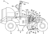
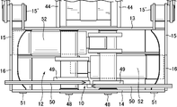
図1乃至3を参照すると、本発明による自走木材伐倒搬出機1は、車体構造物2を含み、該車体構造物2は、前車体部分3と、該前車体部分3から後方に延びる一対の後車体部分4,4とを有する。前輪5は、前車体部分から枢支されたステアリングフレーム6に装着され、また後輪7は、一対の後車体部分4,4にそれぞれ装着され、これら前輪及び後輪は、詳細には図示されていいが、それぞれ油圧モータを内蔵していて油圧モータにより回転駆動されるようになっている。また前輪5は、これと関連した一般的に周知の舵取り機構により油圧的に舵取りされるようになっている。前輪及び後輪は図示した例では、タイヤ式のものであるが、クローラ式のものであってもよい。前車体部分3には、エンジン部及びエンジンで駆動される油圧ポンプ,バッテリー並びに制御バルブ群等が搭載される。
Referring to FIGS. 1 to 3, a self-propelled wood felling unloader 1 according to the present invention includes a vehicle body structure 2, the vehicle body structure 2 extending rearward from a front vehicle body portion 3 and the front vehicle body portion 3. It has a pair of rear vehicle body parts 4, 4. The front wheels 5 are mounted on a steering frame 6 pivotally supported from the front vehicle body portion, and the rear wheels 7 are mounted on a pair of rear vehicle body portions 4 and 4, respectively, the front wheels and the rear wheels being shown in detail. However, each has a built-in hydraulic motor and is driven to rotate by the hydraulic motor. Further, the front wheels 5 are hydraulically steered by a generally known steering mechanism associated therewith. In the illustrated example, the front wheels and the rear wheels are of the tire type, but may be of the crawler type. The front vehicle body part 3 is equipped with an engine part, a hydraulic pump driven by the engine, a battery, a control valve group, and the like.
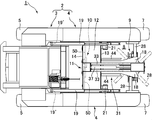
図4乃至6で明らかなように、一対の後車体部分4,4間には、空間8が画成され、その空間に、後述するようにグラップル装置9及び切断装置10が装着される回転フレーム11が配置されている。回転フレーム11は、切断装置10が配置されるカッターボックス12を構成する前後支持板13,14とそれらに連結された一対のサイドアーム15として機能する側板16と、前後支持板の中央上縁に固定された上支持板17及び前支持板13から前方に延びる二股状の底支持板18,18と、を含む。
As is apparent from FIGS. 4 to 6, a space 8 is defined between the pair of rear vehicle body parts 4 and 4, and a rotary frame in which a grapple device 9 and a cutting device 10 are mounted in the space 8 as described later. 11 are arranged. The rotating frame 11 includes front and rear support plates 13 and 14 that constitute a cutter box 12 in which the cutting device 10 is arranged, side plates 16 that function as a pair of side arms 15 connected to the front and rear support plates, and a central upper edge of the front and rear support plates. A fixed upper support plate 17 and a bifurcated bottom support plate 18, 18 extending forward from the front support plate 13.
回転フレーム11は、一端が車体構造物2に19’で枢着された油圧シリンダー19のプランジャーロッドの伸縮によりリンク機構20を介して後車体部分4,4にそれぞれに設けられた枢軸21のまわりに回動するようになっている。リンク機構20は、前記油圧シリンダー19のプランジャーロッドに枢着されたリンク22と、前記枢軸21に回動自在に取り付けられ,一端が前記リンク22に22’で枢着され、他端が回転フレーム11のサイドアーム15の下端に15’で固定的に連結されたベルクランク23と、一端が前記リンク22の中間部に22’で枢着され、他端が後車体部分に設けられた枢軸24に回転自在に取り付けられた支持リンク25とを含む。かくして、枢軸21のまわりの回転フレーム11の回転により、グラップル装置9及び切断装置10は、垂直位置から水平位置にまたその反対に水平位置から垂直位置に向き変えされる。
The rotary frame 11 has a pivot shaft 21 provided on each of the rear vehicle body parts 4 and 4 through a link mechanism 20 by expansion and contraction of a plunger rod of a hydraulic cylinder 19 one end of which is pivotally attached to the vehicle body structure 2 at 19 '. It is designed to rotate around. The link mechanism 20 is rotatably attached to a link 22 pivotally attached to a plunger rod of the hydraulic cylinder 19 and the pivot shaft 21, and has one end pivotally attached to the link 22 at 22 'and the other end rotating. A bell crank 23 fixedly connected to the lower end of the side arm 15 of the frame 11 at 15 ', and a pivot that is pivotally attached at one end to the middle portion of the link 22 at 22' and the other end to the rear vehicle body part. And a support link 25 rotatably attached to 24. Thus, rotation of the rotating frame 11 about the pivot 21 causes the grapple device 9 and the cutting device 10 to be diverted from a vertical position to a horizontal position and vice versa.
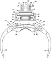
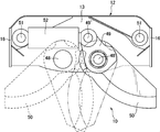
グラップル装置9は、図7乃至9に詳細に示すように、グラブルブラケット26と、ベルクランクの形をなし、グラブルブラケット26の左右一対の枢軸27,27にそれぞれ回転可能に取り付けられた一対のグラップル28,28と、前記枢軸に取り付けられ、各グラップルの上端に28’,28’で枢着されたプランジャーロッドを有する油圧シタンダー29,29と、を含む。かくして、2つの油圧シリンダー29,29の作動によるプランジャーロッドの伸縮で一対のグラップル28,28を閉じたり開いたりして後述するように木を抱き抱えたり開放したりすることができる。グラップルの開閉を同調させるために、よく知られたタイミングロッド30が、一方のグラップルの枢軸27より下方で、また他方のグラップルの枢軸27より上方でグラップル28,28に枢着連結されている。
As shown in detail in FIGS. 7 to 9, the grapple device 9 has a shape of a gable bracket 26 and a bell crank, and a pair of left and right pivots 27, 27 of the gable bracket 26 are rotatably attached to the pair of grapple brackets. Of the grapples 28, 28 and hydraulic studders 29, 29 attached to said pivots and having a plunger rod pivotally attached 28 ', 28' to the upper end of each grapple. Thus, the pair of grapples 28, 28 can be closed or opened by the expansion and contraction of the plunger rod by the operation of the two hydraulic cylinders 29, 29 to hold or open the tree as described later. A well-known timing rod 30 is pivotally connected to the grapples 28, 28 below the pivot 27 of one grapple and above the pivot 27 of the other grapple to coordinate the opening and closing of the grapple.
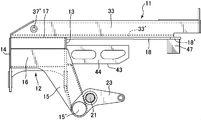
車体構造物は、グラップル装置9のためのガイド装置31を備え、該ガイド装置は、上支持板17及び底支持板18,18と一体をなし、間に空間32を画成する一対の向かい合ったガイドレール33,33と、スライドブラケット34と、を含み、スライドブラケット34は、ガイドレール33,33に係合するガイドローラ35,35を備え、ガイドレール33,33に沿って前後にスライドできるようになっている。グラップル装置9は、スライドブラケット34から懸垂支持されている。ガイドレール33,33間の空間32には、一端がガイドレール間でガイドレールに37’で枢着された油圧シリンダー37が配置され、そのプランジャーロッドは、スライドブラケット34の前方端に設けられた横ピン38に取り付けられている。かくして、油圧シリンダー37の作動によるプランジャーロッドの伸縮で、スライドブラケット34は、ガイドレールに沿って前後方向にスライドし、それにより、グラップル装置9を前方位置と後方位置との間で移動させる。
The vehicle body structure comprises a guide device 31 for the grapple device 9, said guide device being integral with the top support plate 17 and the bottom support plates 18, 18, with a pair of opposed faces defining a space 32 therebetween. The slide bracket 34 includes guide rails 33 and 33 and a slide bracket 34. The slide bracket 34 includes guide rollers 35 and 35 that engage with the guide rails 33 and 33, and can slide back and forth along the guide rails 33 and 33. It has become. The grapple device 9 is suspended and supported by the slide bracket 34. In the space 32 between the guide rails 33, 33 is arranged a hydraulic cylinder 37, one end of which is pivotally attached to the guide rail 37 'between the guide rails, and the plunger rod thereof is provided at the front end of the slide bracket 34. Attached to the horizontal pin 38. Thus, the expansion and contraction of the plunger rod by the operation of the hydraulic cylinder 37 causes the slide bracket 34 to slide in the front-rear direction along the guide rail, thereby moving the grapple apparatus 9 between the front position and the rear position.
グラップル装置のスイングブラケット39が回転ベアリング40を介してスライドブラケット34に回転可能に取り付けられている。グラップルブラケット26は、横ピン41を介して、スイングブラケット39に取り付けられ、そのため、グラップル装置のグラップルは、例えば、前に15°,後に15°振れることができる。グラップル装置9のグラップル28,28のこの前後の振れは、グラップル装置9の前方位置に向かう際には、可能にされるが、後方位置では、不可能にされることが望ましい。この目的のために、グラップルブラケット26の上面に設けられた左右一対の接触要素42,42と、前記カッターボックス12の前支持板13から前方に延び、かつ接触要素との接触面43,43をそれぞれ有する一対の板状要素44,44とを含む振れ止めが設けられている。かくして振れ止めは、グラップル装置9が前方位置にあるときには接触要素42、42が板状要素44,44の接触面43,43との接触から外れるため働かず、グラップル装置9は、横ピン41を中心に前後に自由に振れることができるが、グラップル装置9が後方に移動されるときには、接触要素42,42が板状要素44,44の接触面43,43に接触するため働き、グラップル装置の振れは止められる。グラップル装置が、垂直位置から水平位置にまたその反対に水平位置から垂直位置に向き変えされるとき、グラップル装置は、振れ止めされた状態にあるから、グラップル装置が前後方向に振れることはない。
A swing bracket 39 of the grapple device is rotatably attached to the slide bracket 34 via a rotary bearing 40. The grapple bracket 26 is attached to the swing bracket 39 via a lateral pin 41, so that the grapple of the grapple apparatus can swing, for example, 15 ° forward and 15 ° backward. This back and forth deflection of the grapples 28, 28 of the grapple device 9 is preferably enabled when moving towards the front position of the grapple device 9, but not possible in the rear position. For this purpose, a pair of left and right contact elements 42, 42 provided on the upper surface of the grapple bracket 26 and a contact surface 43, 43 extending forward from the front support plate 13 of the cutter box 12 and contacting the contact elements are provided. A steady rest is provided that includes a pair of plate- like elements 44, 44, respectively. Thus, the steady rest does not work when the grapple device 9 is in the forward position, because the contact elements 42, 42 come out of contact with the contact surfaces 43, 43 of the plate- like elements 44, 44, and the grapple device 9 causes the lateral pin 41 to move. Although it can freely swing back and forth to the center, when the grapple device 9 is moved rearward, the contact elements 42, 42 work for contacting the contact surfaces 43, 43 of the plate- like elements 44, 44, so that the grapple device 9 The swing is stopped. When the grapple device is turned from the vertical position to the horizontal position and vice versa from the horizontal position to the vertical position, the grapple device is in a resting state so that the grapple device does not swing back and forth.
また、グラップル装置9は、前方位置では、スイングブラケット39の旋回により左右に振れることができるようになっている。しかし、グラップル装置は、これが前方位置から後方位置に移動されるとき振れ止めされることが望ましい。この振れ止めは、スイングブラケット39の前方突出部39’に植設されたスタンドピン45の先端に設けられたローラ46が、ガイドレール33,33の間に前方から入り込めるように位置し、グラップル装置9が前方位置から後方位置に移動されるとき、ガイドレール33,33の下部の向かい合わせ面33’,33’に接触することによって達成される。前方位置においては、ローラ46がガイドレール間から抜け出し、スイングブラケット39が 自由に旋回できるので、グラップルの左右の振れは、可能になる。しかし、前記スタンドピン45が、前記二股状の底支持板18,18の左右張出部18’,18’の下面に下向きに突設された一対のストッパー47,47に当たることによって、例えば、左に45°,右に45°に制限される。
Also, the grapple device 9 can swing to the left and right by turning the swing bracket 39 at the front position. However, it is desirable that the grapple device be steady when it is moved from the front position to the rear position. This steady rest is located so that the roller 46 provided at the tip of the stand pin 45 planted in the front protruding portion 39 ′ of the swing bracket 39 can enter between the guide rails 33, 33 from the front, and the grapple device This is achieved by contacting the lower facing surfaces 33 ', 33' of the guide rails 33, 33 when the 9 is moved from the front position to the rear position. At the front position, the roller 46 slips out from between the guide rails, and the swing bracket 39 can freely swing, so that the grapple can swing to the left and right. However, when the stand pin 45 hits a pair of stoppers 47, 47 projecting downward on the lower surfaces of the left and right projecting portions 18 ', 18' of the bifurcated bottom support plates 18, 18, for example, left Is limited to 45 ° to the right and 45 ° to the right.
カッターボックス12の中には、切断装置10が配置される。切断装置10は、図10乃至12で明らかなように、カッターボックス12の前後支持板13,14に固定して取り付けられた一対の枢軸48,48に回転可能に設けられた取付けアーム49,49に固定して取付けられた二枚刃50,50(図11では、そのうちの1つは、刃の取付けをはっきりさせるために省略されて破線で示す)と、前後支持板13,14に固定して取り付けられた一対の枢軸51,51に取り付けられ、取付けアーム49,49に49’,49’で枢着されたプランジャーロッドを有する油圧シリンダー52,52とを含む。かくして、二枚刃50,50は、油圧シリンダー52,52のプランジャーロッドの伸縮により枢軸48,48のまわりに回転して木の切断操作のため開閉される。
The cutting device 10 is arranged in the cutter box 12. As is clear from FIGS. 10 to 12, the cutting device 10 has mounting arms 49, 49 rotatably provided on a pair of pivots 48, 48 fixedly mounted on the front and rear support plates 13, 14 of the cutter box 12. Fixedly attached to the two blades 50, 50 (in FIG. 11, one of which is omitted for clarity of the blade attachment and shown in broken lines) and fixed to the front and rear support plates 13, 14. Hydraulic cylinders 52, 52 mounted on a pair of pivot shafts 51, 51 having a plunger rod pivotally mounted 49 ', 49' on the mounting arms 49, 49. Thus, the two blades 50, 50 are rotated about the pivots 48, 48 by the expansion and contraction of the plunger rod of the hydraulic cylinders 52, 52 to be opened and closed for the cutting operation of the tree.
図13は、一枚刃50を含む切断装置10を示し、一枚刃50は、カッターボックスス12の前後支持板13,14に固定して取り付けられた枢軸48に回転可能に設けられた取付けアーム49に固定して取付けられている。油圧シリンダー52が、前後支持板13,14に固定して取り付けられた枢軸51に取り付けられ、かつ取付けアーム49に49’で枢着されたプランジャーロッドを有する。かくして、一枚刃50は、油圧シリンダー52のプランジャーロッドの伸長により、木の切断操作のため枢軸48のまわりに回転する。
FIG. 13 shows a cutting device 10 including a single blade 50, which is rotatably mounted on a pivot 48 fixedly attached to the front and rear support plates 13 and 14 of the cutter box 12. It is fixedly attached to the arm 49. A hydraulic cylinder 52 has a plunger rod mounted on a pivot 51 fixedly mounted on the front and rear support plates 13, 14 and pivotally mounted 49 'on a mounting arm 49. Thus, the single blade 50 rotates about the pivot 48 for the cutting operation of the wood due to the extension of the plunger rod of the hydraulic cylinder 52.
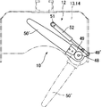
図14は、チエーンソー50’を含む切断装置10を示す。チエーンソー50’は、カッターボックスス12の前後支持板13,14に固定して取り付けられた枢軸48に回転可能に設けられた取付けアーム49に固定して取付けられている。油圧シリンダー52が、前後支持板13,14に固定して取り付けられた枢軸51に取り付けられ、かつ取付けアーム49に49’で枢着されたプランジャーロッドを有する。かくして、チエーンソー50’は、油圧シリンダー52のプランジャーロッドの収縮により、木の切断操作のため枢軸48のまわりに回転する。
FIG. 14 shows a cutting device 10 including a chain saw 50 '. The chain saw 50 'is fixedly attached to a mounting arm 49 rotatably provided on a pivot 48 fixedly attached to the front and rear support plates 13 and 14 of the cutter box 12. A hydraulic cylinder 52 has a plunger rod mounted on a pivot 51 fixedly mounted on the front and rear support plates 13, 14 and pivotally mounted 49 'on a mounting arm 49. Thus, the chain saw 50 'rotates about the pivot 48 for the cutting operation of the tree due to the contraction of the plunger rod of the hydraulic cylinder 52.
なお、参照番号53は、油圧駆動式ウインチを指し、54は、ウインチから繰り出されるワイヤーのためのスイングガイドシーブを指している。このウインチは、立木に縛り付けたワイヤーを巻き取ることにより、車両が急勾配な林地を昇り降りできるようにするために設置される。
Note that reference numeral 53 indicates a hydraulic drive winch, and reference numeral 54 indicates a swing guide sheave for a wire paid out from the winch. This winch is installed so that the vehicle can climb up and down steep forests by winding a wire tied to a standing tree.
操作において、本発明による自走式木材伐倒搬出車の全ての油圧シリンダー及び油圧モータは、ラジコン操作により受信器及び制御弁群を介して遠隔的に作動されるようになっている。なお、木材伐倒搬出車の走行状態及び立木の伐倒作業は、木材伐倒搬出車に適宜設置されるカメラからの映像をモニターすることによって把握されるようになっている。
In operation, all the hydraulic cylinders and hydraulic motors of the self-propelled timber felling and unloading vehicle according to the present invention are designed to be operated remotely via a receiver and a control valve group by radio control operation. It should be noted that the running state of the car for felling timber and the work for felling standing trees can be grasped by monitoring images from a camera appropriately installed in the car for felling timber.
立木の伐倒及び木材の搬出作業について、限られる訳ではないがその手順を以下に説明する。通常は、回転フレーム11は、グラップル装置9及び切断装置10が車体構造物に対して垂直位置にあるように位置決めされ、グラップル装置9は、車体構造物2の前方位置にあるものとする。この状態では、グラップル28,28は閉じ、二枚刃50,50又は一枚刃50は開いており、又チエーンソー50’はカッターボックス内に引っ込められている。伐倒作業は、水平な林地でばかりでなく傾斜林地でほぼ垂直に育っている立木に対して行なわれるのが一般的である。
The procedures for felling standing trees and carrying out timber are explained below, but are not limited to these. Normally, the rotating frame 11 is positioned so that the grapple device 9 and the cutting device 10 are in a vertical position with respect to the vehicle body structure, and the grapple device 9 is assumed to be in a front position of the vehicle body structure 2. In this state, the grapples 28, 28 are closed, the double blade 50, 50 or the single blade 50 is open, and the chain saw 50 'is retracted into the cutter box. The felling work is generally performed not only on horizontal forests but also on standing trees that grow almost vertically in sloping forests.
油圧シリンダー37の作動によりスライドブラケット34をガイドレール33,33に沿って移動させることによってグラップル装置9を、前方位置から後方位置まで後方にスライドさせる。次いで、油圧シリンダー19,19の作動によりリンク機構20,20を介して回転フレーム11を枢軸21,21のまわりに回転させ、ガイド装置31を車体構造物に対して水平位置から垂直位置に向き変えする。この方法で、グラップル装置9のグラップル28,28及び切断装置10の二枚刃50,50又は一枚刃50若しくはチエーンソー50’は、垂直位置から水平位置に向き変えされる。この状態において、グラップル28,28を油圧シリンダー29,29の作動によりプランジャーロッドを収縮させて枢軸27,27のまわりに外向きに回転させて開く。次いで、木材伐倒搬出車1を伐倒すべき立木に向かって走行させ、グラップル28,28を油圧シリンダー29,29の作動によりプランジャーロッドを伸張させて枢軸27,27のまわりに内向きに回転させて閉じ、立木を抱き抱えてこれを保持する。次いで油圧シリンダー52,52の作動によりプランジャーロッドを伸張させて二枚刃50,50を枢軸51,51のまわりに互いに反対方向に回転させることにより、一枚刃50の場合には、一枚刃50を枢軸51のまわりに外から内へ回転させることにより、チエーンソー50’の場合には、作動させた状態において、油圧シリンダー52のプランジャーロッドの収縮によりチエーンソー50’を枢軸51のまわりに内から外に回転させることにより、立木を切断する。切断後、油圧シリンダー37及び油圧シリンダー19,19を順次作動してそれらのプランジャーロッドを伸張させ、それによりスライドブラケット34、したがってグラップルをガイドレール33,33に沿って移動させ、また回転フレーム11を枢軸21のまわりに逆転させることによって立木を伐倒させる。カッターは、切断後もとの位置に戻されることは明らかである。グラップルがガイドレール33,33に沿って移動し始める段階で、グラップルは、切断された立木を切り株から持ち上げるように作用し、そのため、立木の伐倒が容易に行なわれることは理解されよう。伐倒し終わったときには、グラップルは、下向きで前方位置にあり、かくして、木材伐倒搬出機を、後方に即ち立木のあった場所から離れる方向に走行させることにより、伐倒した木を地形に沿って引きずりながら搬出する。グラップル装置は、その前方位置では、前後左右に振れるように構成されているから、引きずられる木材は、林地の地形に巧く順応し、また車両が左右に曲がろうとするとき、車両に余分な負荷を及ぼすことがない。
By operating the hydraulic cylinder 37 to move the slide bracket 34 along the guide rails 33, 33, the grapple device 9 is slid backward from the front position to the rear position. Then, by operating the hydraulic cylinders 19 and 19, the rotary frame 11 is rotated around the pivots 21 and 21 via the link mechanisms 20 and 20, and the guide device 31 is turned from the horizontal position to the vertical position with respect to the vehicle body structure. To do. In this way, the grapples 28, 28 of the grapple device 9 and the two- blade 50, 50 or the single-blade 50 or the chain saw 50 'of the cutting device 10 are turned from a vertical position to a horizontal position. In this state, the grapples 28, 28 are opened by rotating the hydraulic rods 29, 29 outwardly around the pivots 27, 27 by contracting the plunger rod. Then, the timber felling delivery vehicle 1 is run toward the standing tree to be felled, and the grapples 28, 28 are rotated inwardly around the pivots 27, 27 by extending the plunger rod by the operation of the hydraulic cylinders 29, 29. Let it close and hold the tree by hugging it. Then, by actuating the hydraulic cylinders 52, 52, the plunger rod is extended to rotate the two blades 50, 50 in opposite directions about the pivots 51, 51. By rotating the blade 50 from outside to inside about the pivot 51, in the case of the chain saw 50 ′, the chain saw 50 ′ is moved around the pivot 51 by the contraction of the plunger rod of the hydraulic cylinder 52 in the activated state. The standing tree is cut by rotating it from inside to outside. After cutting, the hydraulic cylinder 37 and the hydraulic cylinders 19, 19 are operated in sequence to extend their plunger rods, thereby moving the slide bracket 34 and thus the grapple along the guide rails 33, 33, and also the rotating frame 11. The standing tree is felled by reversing around the axis 21. It is clear that the cutter is returned to its original position after cutting. It will be appreciated that as the grapple begins to move along the guide rails 33, 33, the grapple acts to lift the cut stand from the stump, thus facilitating felling of the stand. At the end of the felling, the grapple is in a downward and forward position, thus running the felling tree backwards, i.e. away from the place where the standing trees were, to bring the felled trees along the terrain. And drag it out. In its forward position, the grapple device is constructed so that it can swing back and forth and left and right, so that the timber that is dragged adapts well to the terrain of the forest and when the vehicle tries to turn left or right, it does No load is applied.
傾斜林地では、図15及び16に示すように、回転フレームを、グラップル装置9のグラップル28,28及び切断装置10の二枚刃50,50又は一枚刃50若しくはチエーンソー50’が立木に対してほぼ直角に向かう程度に回転させことになる。
In a sloping forest, as shown in FIGS. 15 and 16, the rotating frame is provided such that the grapples 28, 28 of the grapple device 9 and the double blades 50, 50 or the single blade 50 or the chain saw 50 ′ of the cutting device 10 are used for standing trees. It will be rotated so that it goes to a right angle.
本発明による木材伐倒搬出機は、グラップルにより、横倒しになっている木材を掴んでそれを搬出するのにも利用することができる。
The wood felling unloader according to the present invention can also be used to grab a lying wood by a grapple and carry it out.
1 木材伐倒搬出機
2 走行車体構造物
3 前車体部分
4 後車体部分
5 前輪
7 後輪
8 空間
9 グラップル装置
10 切断装置
11 回転フレーム
12 カッターボックス
13 前支持板
14 後支持板
15 サイドアーム
18 二股状底支持板
19 油圧シリンダー
20 リンク機構
21 枢軸
26 グラップルブラケット
28 グラップル
29 油圧シリンダー
31 ガイド装置
32 空間
33 ガイドレール
34 スライドブラケット
37 油圧シリンダー
48 枢軸
50 二枚刃,一枚刃
50’ チエーンソー
52 油圧シリンダー 1Wood felling unloader 2 Traveling car body structure 3 Front car body part 4 Rear car body part 5 Front wheel 7 Rear wheel 8 Space 9 Grapple device 10 Cutting device 11 Rotating frame 12 Cutter box 13 Front support plate 14 Rear support plate 15 Side arm 18 Bifurcated Bottom Support Plate 19 Hydraulic Cylinder 20 Link Mechanism 21 Axis 26 Grapple Bracket 28 Grapple 29 Hydraulic Cylinder 31 Guide Device 32 Space 33 Guide Rail 34 Slide Bracket 37 Hydraulic Cylinder 48 Axis 50 Two-Flute, One-Flute 50 'Chain Saw 52 Hydraulic cylinder
2 走行車体構造物
3 前車体部分
4 後車体部分
5 前輪
7 後輪
8 空間
9 グラップル装置
10 切断装置
11 回転フレーム
12 カッターボックス
13 前支持板
14 後支持板
15 サイドアーム
18 二股状底支持板
19 油圧シリンダー
20 リンク機構
21 枢軸
26 グラップルブラケット
28 グラップル
29 油圧シリンダー
31 ガイド装置
32 空間
33 ガイドレール
34 スライドブラケット
37 油圧シリンダー
48 枢軸
50 二枚刃,一枚刃
50’ チエーンソー
52 油圧シリンダー 1
Claims (6)
- タイヤ式又は覆帯式走行車体構造物の内部空間に、立木を横から抱き抱えて保持するための一対のグラップルを有するグラップル装置及び立木を伐倒するため、立木を横から切断するための一対のカッターを有する切断装置を備えた回転フレームと、該回転フレームを、グラップル装置及び切断装置の垂直位置と水平位置との間で回転させるための装置とを設け、グラップル装置のグラップルが、回転フレームの逆回転により立木を伐倒させ、伐倒後、木材伐倒搬出機の走行によりグラップル装置のグラップルが伐倒した木材を搬出するようにした自走式木材伐倒搬出機。 A grapple device having a pair of grapples for holding and holding a standing tree from the side in the internal space of a tire-type or band-type traveling vehicle body structure and a pair for cutting the standing tree from the side in order to fell the standing tree. And a device for rotating the rotating frame between a vertical position and a horizontal position of the grapple device and the cutting device, wherein the grapple of the grapple device is a rotating frame. A self-propelled timber felling and unloading machine that cuts down standing trees by reverse rotation of, and after the felling, the grapple of the grapple device carries out the felled wood by running the timber felling and unloading machine.
- 走行車体構造物は、前車体部分と、内部空間を画成する一対の二股状の後車体部分とを含み、回転フレームは、内部空間内にあって、後車体部分に固定された枢軸に回転自在に取り付けられ、回転フレームを回転させるための装置は、回転フレームにリンク機構を介して連結された油圧シリンダーを含む、請求項1に記載の自走式木材伐倒搬出機。 The traveling vehicle body structure includes a front vehicle body portion and a pair of bifurcated rear vehicle body portions that define an internal space, and the rotating frame is in the internal space and rotates on a pivot fixed to the rear vehicle body portion. The self-propelled wood felling and unloading machine according to claim 1, wherein the device for freely rotating and rotating the rotating frame includes a hydraulic cylinder connected to the rotating frame via a link mechanism.
- 回転フレームは、前記切断装置を設置するカッターボックスと、ガイド装置とを含み、ガイド装置は、一対のガイドレールと、スライドブラケットと、該スライドブラケットをガイドレールに沿って前後方向に摺動させるための油圧シリンダー、とを含み、前記グラップル装置は、前記スライドブラケットから懸垂され、前記スライドブラケットの摺動により、グラップル装置を前方位置と後方位置との間で移動させる、請求項1に記載の自走式木材伐倒搬出機。 The rotating frame includes a cutter box for installing the cutting device and a guide device, and the guide device includes a pair of guide rails, a slide bracket, and a slide bracket for sliding the slide bracket in the front-rear direction along the guide rail. The hydraulic cylinder according to claim 1, wherein the grapple device is suspended from the slide bracket, and the sliding of the slide bracket moves the grapple device between a front position and a rear position. Traveling timber felling unloader.
- 前記切断装置は、カッターボックスの中に配置され、カッターボックスの前後支持板に固定された一対の枢軸に回転自在に取付けられた二枚刃と、該二枚刃を前記枢軸の回りに互いに反対方向に回転させるための油圧シリンダーと、を含む、請求項1に記載の自走式木材伐倒搬出機。 The cutting device is arranged in a cutter box and is rotatably attached to a pair of pivots fixed to front and rear support plates of the cutter box, and the two blades are opposite to each other around the pivot. A self-propelled wood felling and unloading machine according to claim 1, further comprising a hydraulic cylinder for rotating in a direction.
- 切断装置は、カッターボックスの中に配置され、カッターボックスの前後支持板に固定された枢軸に回転自在に取付けられた取付けアームに固定して取付けられた一枚刃と、該一枚刃を前記枢軸のまわりに外から内に回転させるための油圧シリンダーと、を含む、請求項1に記載の自走式木材伐倒搬出機。 The cutting device is arranged in the cutter box, and is fixedly mounted on a mounting arm rotatably mounted on a pivot fixed to the front and rear support plates of the cutter box, and the single blade is A self-propelled wood felling unloader according to claim 1, including a hydraulic cylinder for rotating from outside to inside about a pivot.
- 切断装置は、カッターボックスの中に配置され、カッターボックスの前後支持板に固定された枢軸に回転自在に取付けられた取付けアームに固定して取り付けられたチエーンソーと、該チエーンソーを前記枢軸のまわりに内から外に回転させるための油圧シリンダーと、を含む、請求項1に記載の自走式木材伐倒搬出機。 The cutting device is disposed in the cutter box and is fixedly attached to a mounting arm rotatably attached to a pivot fixed to the front and rear support plates of the cutter box, and the chain saw is provided around the pivot. The self-propelled wood felling and unloading machine according to claim 1, further comprising a hydraulic cylinder for rotating from inside to outside.
Applications Claiming Priority (2)
| Application Number | Priority Date | Filing Date | Title |
|---|---|---|---|
| JP2018210472A JP7125330B2 (en) | 2018-11-08 | 2018-11-08 | Self-propelled logging machine |
| JP2018-210472 | 2018-11-08 |
Publications (1)
| Publication Number | Publication Date |
|---|---|
| WO2020096051A1 true WO2020096051A1 (en) | 2020-05-14 |
Family
ID=70610729
Family Applications (1)
| Application Number | Title | Priority Date | Filing Date |
|---|---|---|---|
| PCT/JP2019/043941 WO2020096051A1 (en) | 2018-11-08 | 2019-11-08 | Self-propelled tree felling/shipping machine |
Country Status (2)
| Country | Link |
|---|---|
| JP (1) | JP7125330B2 (en) |
| WO (1) | WO2020096051A1 (en) |
Citations (5)
| Publication number | Priority date | Publication date | Assignee | Title |
|---|---|---|---|---|
| JPS5715647Y2 (en) * | 1978-05-12 | 1982-04-01 | ||
| JPS5725879Y2 (en) * | 1977-04-11 | 1982-06-04 | ||
| JP2010213697A (en) * | 2009-03-16 | 2010-09-30 | Lauri Kalervo Ketonen | Multi-processing machine |
| JP2013176316A (en) * | 2012-02-28 | 2013-09-09 | Iseki & Co Ltd | Seedling transplanter |
| JP6288949B2 (en) * | 2013-05-23 | 2018-03-07 | 松本 良三 | Standing tree cutting device |
Family Cites Families (3)
| Publication number | Priority date | Publication date | Assignee | Title |
|---|---|---|---|---|
| FR2955730A1 (en) | 2010-01-25 | 2011-07-29 | Thomson Licensing | CODING AND DECODING METHODS |
| JP5725879B2 (en) | 2011-01-24 | 2015-05-27 | キヤノン株式会社 | Image forming apparatus |
| JP2013176315A (en) * | 2012-02-28 | 2013-09-09 | Yanmar Co Ltd | Semi-crawler type working vehicle |
-
2018
- 2018-11-08 JP JP2018210472A patent/JP7125330B2/en active Active
-
2019
- 2019-11-08 WO PCT/JP2019/043941 patent/WO2020096051A1/en active Application Filing
Patent Citations (5)
| Publication number | Priority date | Publication date | Assignee | Title |
|---|---|---|---|---|
| JPS5725879Y2 (en) * | 1977-04-11 | 1982-06-04 | ||
| JPS5715647Y2 (en) * | 1978-05-12 | 1982-04-01 | ||
| JP2010213697A (en) * | 2009-03-16 | 2010-09-30 | Lauri Kalervo Ketonen | Multi-processing machine |
| JP2013176316A (en) * | 2012-02-28 | 2013-09-09 | Iseki & Co Ltd | Seedling transplanter |
| JP6288949B2 (en) * | 2013-05-23 | 2018-03-07 | 松本 良三 | Standing tree cutting device |
Also Published As
| Publication number | Publication date |
|---|---|
| JP2020074717A (en) | 2020-05-21 |
| JP7125330B2 (en) | 2022-08-24 |
Similar Documents
| Publication | Publication Date | Title |
|---|---|---|
| US8992159B2 (en) | Log loader | |
| US3087296A (en) | Brush cutter | |
| US4326571A (en) | Mobile device for handling material | |
| US3732904A (en) | Modified processor and components | |
| US3664391A (en) | Tree cutting and piling apparatus | |
| JP4091100B1 (en) | Bamboo felling attachment and bamboo felling machine equipped with the same | |
| AU2011200196B2 (en) | Tree Felling And Grappling Head | |
| US9795091B2 (en) | Tree felling and grappling head | |
| US4583908A (en) | Mobile device for handling material | |
| US3643712A (en) | Tree-shearing head | |
| US3464468A (en) | Tree shearing,topping,and delimbing apparatus | |
| AU566185B2 (en) | Swath cutting gripping tree delimber | |
| US4412777A (en) | Device for a felling and gripping unit | |
| RU2202483C2 (en) | Machine for and method of transportation of felled trees | |
| US3882910A (en) | Timber harvester | |
| EP3097771B1 (en) | Forestry machine | |
| US3461929A (en) | Deep snow butt shear apparatus | |
| WO2020096051A1 (en) | Self-propelled tree felling/shipping machine | |
| US3961468A (en) | Hedger | |
| JP5469982B2 (en) | Grapple device and hydraulic excavator | |
| US5355920A (en) | Felling and delimbing apparatus allowing to delimb trees in length and its method of use | |
| US3595288A (en) | Tree harvesting method and apparatus | |
| US3805859A (en) | Delimbing assembly for a tree harvester | |
| US3823753A (en) | Tree harvester with supplemental grapple | |
| US3683979A (en) | Timber harvester |
Legal Events
| Date | Code | Title | Description |
|---|---|---|---|
| 121 | Ep: the epo has been informed by wipo that ep was designated in this application |
Ref document number: 19882337 Country of ref document: EP Kind code of ref document: A1 |
|
| NENP | Non-entry into the national phase |
Ref country code: DE |
|
| 122 | Ep: pct application non-entry in european phase |
Ref document number: 19882337 Country of ref document: EP Kind code of ref document: A1 |