WO2020095923A1 - 車両用表示装置及び車両用表示システム - Google Patents
車両用表示装置及び車両用表示システム Download PDFInfo
- Publication number
- WO2020095923A1 WO2020095923A1 PCT/JP2019/043389 JP2019043389W WO2020095923A1 WO 2020095923 A1 WO2020095923 A1 WO 2020095923A1 JP 2019043389 W JP2019043389 W JP 2019043389W WO 2020095923 A1 WO2020095923 A1 WO 2020095923A1
- Authority
- WO
- WIPO (PCT)
- Prior art keywords
- display
- vehicle
- curved portion
- display device
- virtual image
- Prior art date
- Legal status (The legal status is an assumption and is not a legal conclusion. Google has not performed a legal analysis and makes no representation as to the accuracy of the status listed.)
- Ceased
Links
Images






Classifications
-
- B—PERFORMING OPERATIONS; TRANSPORTING
- B60—VEHICLES IN GENERAL
- B60K—ARRANGEMENT OR MOUNTING OF PROPULSION UNITS OR OF TRANSMISSIONS IN VEHICLES; ARRANGEMENT OR MOUNTING OF PLURAL DIVERSE PRIME-MOVERS IN VEHICLES; AUXILIARY DRIVES FOR VEHICLES; INSTRUMENTATION OR DASHBOARDS FOR VEHICLES; ARRANGEMENTS IN CONNECTION WITH COOLING, AIR INTAKE, GAS EXHAUST OR FUEL SUPPLY OF PROPULSION UNITS IN VEHICLES
- B60K35/00—Instruments specially adapted for vehicles; Arrangement of instruments in or on vehicles
- B60K35/10—Input arrangements, i.e. from user to vehicle, associated with vehicle functions or specially adapted therefor
-
- B—PERFORMING OPERATIONS; TRANSPORTING
- B60—VEHICLES IN GENERAL
- B60K—ARRANGEMENT OR MOUNTING OF PROPULSION UNITS OR OF TRANSMISSIONS IN VEHICLES; ARRANGEMENT OR MOUNTING OF PLURAL DIVERSE PRIME-MOVERS IN VEHICLES; AUXILIARY DRIVES FOR VEHICLES; INSTRUMENTATION OR DASHBOARDS FOR VEHICLES; ARRANGEMENTS IN CONNECTION WITH COOLING, AIR INTAKE, GAS EXHAUST OR FUEL SUPPLY OF PROPULSION UNITS IN VEHICLES
- B60K35/00—Instruments specially adapted for vehicles; Arrangement of instruments in or on vehicles
- B60K35/20—Output arrangements, i.e. from vehicle to user, associated with vehicle functions or specially adapted therefor
- B60K35/21—Output arrangements, i.e. from vehicle to user, associated with vehicle functions or specially adapted therefor using visual output, e.g. blinking lights or matrix displays
- B60K35/22—Display screens
-
- B—PERFORMING OPERATIONS; TRANSPORTING
- B60—VEHICLES IN GENERAL
- B60K—ARRANGEMENT OR MOUNTING OF PROPULSION UNITS OR OF TRANSMISSIONS IN VEHICLES; ARRANGEMENT OR MOUNTING OF PLURAL DIVERSE PRIME-MOVERS IN VEHICLES; AUXILIARY DRIVES FOR VEHICLES; INSTRUMENTATION OR DASHBOARDS FOR VEHICLES; ARRANGEMENTS IN CONNECTION WITH COOLING, AIR INTAKE, GAS EXHAUST OR FUEL SUPPLY OF PROPULSION UNITS IN VEHICLES
- B60K35/00—Instruments specially adapted for vehicles; Arrangement of instruments in or on vehicles
- B60K35/20—Output arrangements, i.e. from vehicle to user, associated with vehicle functions or specially adapted therefor
- B60K35/21—Output arrangements, i.e. from vehicle to user, associated with vehicle functions or specially adapted therefor using visual output, e.g. blinking lights or matrix displays
- B60K35/23—Head-up displays [HUD]
- B60K35/231—Head-up displays [HUD] characterised by their arrangement or structure for integration into vehicles
-
- B—PERFORMING OPERATIONS; TRANSPORTING
- B60—VEHICLES IN GENERAL
- B60K—ARRANGEMENT OR MOUNTING OF PROPULSION UNITS OR OF TRANSMISSIONS IN VEHICLES; ARRANGEMENT OR MOUNTING OF PLURAL DIVERSE PRIME-MOVERS IN VEHICLES; AUXILIARY DRIVES FOR VEHICLES; INSTRUMENTATION OR DASHBOARDS FOR VEHICLES; ARRANGEMENTS IN CONNECTION WITH COOLING, AIR INTAKE, GAS EXHAUST OR FUEL SUPPLY OF PROPULSION UNITS IN VEHICLES
- B60K35/00—Instruments specially adapted for vehicles; Arrangement of instruments in or on vehicles
- B60K35/20—Output arrangements, i.e. from vehicle to user, associated with vehicle functions or specially adapted therefor
- B60K35/29—Instruments characterised by the way in which information is handled, e.g. showing information on plural displays or prioritising information according to driving conditions
-
- B—PERFORMING OPERATIONS; TRANSPORTING
- B60—VEHICLES IN GENERAL
- B60K—ARRANGEMENT OR MOUNTING OF PROPULSION UNITS OR OF TRANSMISSIONS IN VEHICLES; ARRANGEMENT OR MOUNTING OF PLURAL DIVERSE PRIME-MOVERS IN VEHICLES; AUXILIARY DRIVES FOR VEHICLES; INSTRUMENTATION OR DASHBOARDS FOR VEHICLES; ARRANGEMENTS IN CONNECTION WITH COOLING, AIR INTAKE, GAS EXHAUST OR FUEL SUPPLY OF PROPULSION UNITS IN VEHICLES
- B60K35/00—Instruments specially adapted for vehicles; Arrangement of instruments in or on vehicles
- B60K35/80—Arrangements for controlling instruments
Definitions
- the present disclosure relates to a vehicle display device and a vehicle display system.
- a vehicle display device configured to be installed in a vehicle.
- the display surface covered with the exposed translucent plate in order to realize a pseudo curved surface is installed upright.
- the exposed translucent plate is curved in a concave shape.
- the present disclosure aims to provide a display device for a vehicle and a display system for a vehicle, which makes it easy to grasp the display content by expressing a bird's-eye view feeling to the user.
- a vehicular display device configured to be installed in a vehicle has a plurality of bending portions that are curved with a curvature provided in a front-rear direction from a front side to a rear side of the vehicle, The display surface is formed so that a real image can be displayed upward.
- the plurality of curved portions have a concave curved portion that is curved in a concave shape and a convex curved portion that is curved in a convex shape at positions that are displaced from each other in the depth direction.
- the convex curved portion is arranged on the most front side.
- the concave curved portion and the convex curved portion are provided on the display surface formed so as to be able to display the real image upward.
- the user can visually recognize the display on the display surface having a feeling of height as if looking down.
- the concave curved portion and the convex curved portion which are arranged on the innermost side, are the convex curved portions, so that the rear portion of the display surface is prevented from standing up, and the horizontal portion is suppressed. A sense of spreading in the direction can be generated.
- a vehicular display system configured to be mounted on a vehicle projects display light that can be imaged as a virtual image onto a virtual image forming unit installed in the vehicle.
- a head-up display device and a display surface that has a plurality of curved portions that are curved with a curvature provided in the front-back direction from the rear side to the front side of the vehicle and that displays a real image upward.
- the curving portion has a concave curving portion curving in a concave shape and a convex curving portion curving in a convex shape at portions displaced from each other in the front-rear direction.
- the convex curved portion is arranged on the most front side.
- the frontmost end of the display surface is arranged with respect to the virtual image forming unit so that the real image is displayed behind the virtual image.
- the concave curved portion and the convex curved portion are provided on the display surface formed so as to be able to display the real image upward.
- the user can visually recognize the display on the display surface having a feeling of height as if looking down.
- the concave curved portion and the convex curved portion which are arranged on the innermost side, are the convex curved portions, so that the rear portion of the display surface is prevented from standing up, and the horizontal portion is suppressed. A sense of spreading in the direction can be generated.
- a real image is formed using the virtual image forming unit based on the positional relationship between the innermost end of the display surface and the virtual image forming unit onto which the display light of the head-up display device is projected. Displaying on the front side of the virtual image enables continuous display between the real image and the virtual image. That is, the sense of expansion of the real image display in the depth direction becomes remarkable.
- FIG. 3 is a perspective view showing a state in which the vehicle display system according to the first embodiment is mounted on a vehicle
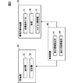
- 1 is a block diagram showing a schematic configuration of a vehicle display system according to a first embodiment
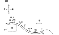
- It is a sectional view showing a section including a depth direction and a vertical surface of a display system for vehicles in a 1st embodiment
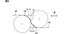
- It is a schematic diagram for explaining the curved form of the display surface
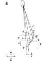
- It is a diagram for explaining a curved form of the display surface and a plurality of display regions
- It is a figure which shows the example of a display in 1st Embodiment
- It is a flow chart by the display system for vehicles of a 1st embodiment
- It is a figure corresponding to FIG.
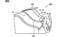
- FIG. 6 is a perspective view showing a state in which the vehicle display system according to the second embodiment is mounted on a vehicle, It is a figure which shows the example of a display by 2nd Embodiment, It is a figure which shows the other display example by 2nd Embodiment, It is a figure which shows the other display example by 2nd Embodiment, It is a figure which shows the other display example by 2nd Embodiment, It is a figure which shows the other display example by 2nd Embodiment, It is a figure which shows the other display example by 2nd Embodiment, It is a figure which shows the other example of a display by 2nd Embodiment.
- the vehicle display device 10 is configured to be installed on the instrument panel 2 of the vehicle 1, as shown in FIG. 1.
- the vehicular display device 10 constitutes a vehicular display system 100 together with a head-up display device (hereinafter, HUD device) 30, a control device 40, and the like.
- the vehicle display device 10 is installed in the instrument panel 2 at a driver's seat facing portion that faces the driver's seat on which the driver as the user of the vehicle display system 100 is seated.
- the directions of up, down, front, rear, left and right are defined with reference to the vehicle 1 on the road surface on which the horizontal plane HP is maintained.
- the vehicle 1 when it is necessary to distinguish the vehicle 1 from other vehicles, it may be referred to as “own vehicle” for convenience.
- the windshield 3 of the vehicle 1 is arranged above the instrument panel 2.
- the windshield 3 is formed of, for example, glass or synthetic resin in a translucent plate shape, and is arranged above the instrument panel 2.
- the windshield 3 is arranged so as to be inclined from the instrument panel 2 as it goes from the front to the rear.
- the vehicle display device 10 is a so-called graphic meter, and has an image display panel 11, a frame portion 18, and an ambient lighting portion 21.
- the image display panel 11 is a curved panel formed in a thin plate shape. More specifically, the image display panel 11 is an EL panel in which pixels capable of self-luminous emission are two-dimensionally arranged by using electroluminescence and have a display surface 12 having a rectangular outline. For this self-emission, organic electroluminescence or inorganic electroluminescence can be used.
- the display surface 12 is formed so as to be exposed on the upper portion of the instrument panel 2 so that the real image RI can be displayed upward.
- the display surface 12 is formed into a curved surface like a ski jumping stand.
- the depth direction DD When the direction from the front side to the back side with respect to the seat on which the driver sits is defined as the depth direction DD, as shown in FIG. 3, the rectangular display surface 12 has its longitudinal direction aligned with the depth direction DD. Are arranged.
- the depth direction DD can be defined along the front-rear direction of the vehicle 1.
- the display surface 12 has a plurality of bending portions 13 that are curved with a curvature provided in the depth direction DD.
- the curved portion 13 is curved with a non-zero curvature set on a cross section including the depth direction DD and the vertical plane.
- one concave bending portion 14 and one convex bending portion 15 are provided on the display surface 12 at positions deviated from each other in the depth direction DD. ..
- the concave curved portion 14 is arranged on the front side of the convex curved portion 15.
- the concave curved portion 14 is curved in a concave shape, and more specifically, is formed in a cylindrical surface shape in which a generatrix extends in a left-right direction orthogonal to the depth direction DD.
- the convex curved portion 15 is arranged farther back than the concave curved portion 14.
- the convex curved portion 15 is curved in a convex shape, and more specifically, is formed in a cylindrical surface shape in which a generatrix extends in the left-right direction.
- the concave curved portion 14 is arranged at the innermost side, not the convex curved portion 15. Further, as shown in FIG. 4, in the present embodiment, the curvature of the concave curved portion 14 and the curvature of the convex curved portion 15 are substantially the same.
- the display surface 12 is not provided with a flat portion. That is, the display surface 12 is entirely occupied by the one concave curved portion 14 and the one convex curved portion 15, and all the portions of the display surface 12 are curved. That is, the entire display surface 12 is S-shaped.
- the concave curved portion 14 reaches the end portion 12a on the most front side of the display surface 12.
- the concave curved portion 14 is formed so that the concave curved portion 14 is closer to the horizontal plane HP as it goes from the rear side portion having an inclined state facing the front side to the front side portion.
- the end 12a on the most front side of the display surface 12 does not reach the horizontal state and a slight gradient is left, so that an inclined state slightly facing the front side is maintained. There is.
- the convex curved portion 15 reaches the farthest end 12b of the display surface 12.
- the convex curved portion 15 is formed so that the convex curved portion 15 is closer to the horizontal plane HP as it goes from the front side portion having an inclined state facing the front side to the rear side portion.
- the end 12b on the farthest side of the display surface 12 does not reach the horizontal state and has a slight gradient, so that the inclined state of slightly facing the front side is maintained. There is.
- the concave curved portion 14 and the convex curved portion 15 are directly and smoothly connected to each other via an inflection point IP whose bending direction changes.
- the term “smooth” as used herein means that the curvature and the first derivative of the curvature have continuity.
- the inflection point IP is expressed as a “point” for convenience, it is strictly set in a “line” shape because the display surface 12 has a width in the left-right direction. It can be broadly understood to include.
- the gradient of the display surface 12 at the inflection point IP is the maximum of the gradients of the respective parts on the display surface 12. Even at the inflection point IP, the display surface 12 does not face directly to the side, but has an upward component and is maintained in an inclined state.
- the slope of the display surface 12 becomes gradually smaller as it goes from the inflection point IP to the near side or the far side, and the shape approaches the horizontal plane HP as described above. In this way, the display surface 12 has a height difference that rises upward from the front side to the back side.
- a liquid crystal panel other than the EL panel may be adopted as long as the curved display surface 12 can be realized.
- the frame 18 is made of, for example, a synthetic resin in a dark color (for example, black), and has a frame shape surrounding the entire circumference of the display surface 12 of the image display panel 11.
- the frame portion 18 has a non-display stretching surface 19 that extends so as to be continuous with the display surface 12 from the farthest end 12 b of the display surface 12 to the further back side.
- the non-display stretched surface 19 is non-displayable and is formed in a flat shape.
- the ambient lighting unit 21 shown in FIG. 1 is provided on the side wall of the device 10 that faces the left-right direction. In other words, the ambient lighting sections 21 are provided on both sides of the display surface 12 in between.
- the ambient illumination unit 21 is provided, for example, by arranging a plurality of light emitting diode elements in the depth direction DD, and illuminates the periphery of the display surface 12.
- the HUD device 30 is configured to be installed on the instrument panel 2 of the vehicle 1, as shown in FIGS.
- the HUD device 30 projects the display light toward the virtual image forming unit 3a formed in the windshield 3 of the vehicle 1 in a planar shape or a concave shape. That is, the driver sitting on the seat can perceive the display light reflected by the virtual image forming unit 3a as the formed virtual image VI.
- the HUD device 30 includes a display unit 31, a reflecting mirror 32, and the like.
- the display unit 31, the reflecting mirror 32, and the like are housed inside a housing having a light shielding property.
- the display 31 displays an image and emits the display light.
- a liquid crystal display using a backlight a display using an EL panel that self-luminesces using electroluminescence, a display using a laser scanner, and a DLP (Digital Micromirror Device) DLP are used. (Digital Light Processing; registered trademark) type display and the like can be adopted.
- the reflecting mirror 32 is formed, for example, by depositing a metal film such as aluminum on the surface of synthetic resin or glass.
- the reflecting mirror 32 has a concave or flat reflecting surface.
- the reflecting mirror 32 reflects the display light emitted from the display 31 toward the virtual image forming unit 3a by the reflecting surface.
- a window 33 is provided on the upper surface of the housing and the upper surface of the instrument panel 2, and the display light reflected by the reflecting mirror 32 passes through the window 33 to the virtual image forming unit 3a.
- the window portion 33 may be mechanically opened by forming an opening hole, or may be optically opened by being blocked by a dust-proof sheet having a light-transmitting property or a semi-light-transmitting property.
- the window 33 is provided by, for example, forming a part of the non-display stretched surface 19 with a dust-proof sheet having a semi-translucent property by coloring in a smoke tone.
- the virtual image forming unit 3a can be set in the vicinity of the end 12b of the display surface 12, and the horizontal position of the virtual image forming unit 3a and the horizontal position of the display surface 12 can be easily adjusted. Can be adjusted to Then, the real image RI displayed on the display surface 12 is displayed in front of the virtual image VI.
- the control device 40 is a so-called computer, and is mainly composed of an electronic circuit including at least one processor, a memory device, and an input / output interface.
- the processor is an arithmetic circuit that executes a computer program stored in the memory device.
- the memory device is a storage medium that is provided by, for example, a semiconductor memory and that temporarily stores computer programs and data that can be read by a processor.
- the control device 40 is communicably connected to the image display panel 11 of the vehicular display device 10 and the display 31 of the HUD device 30, and the real image RI and the display 31 displayed on the display surface 12 by the image display panel 11 are displayed. To control the virtual image VI displayed.
- the control device 40 is configured to be able to acquire various information from the vehicle 1 by inputting an electrical signal using communication.
- the control device 40 has a display area setting unit 41 and a display content allocation unit 42 as functional blocks.
- the display area setting unit 41 sets a plurality of display areas DA1, DA2, DA3 for the real image RI displayed on the display surface 12 and the virtual image VI displayed via the virtual image forming unit 3a.
- the plurality of display areas DA1, DA2, DA3 are arranged so as to be divided in the depth direction DD. Specifically, as shown in FIG. 5, the display area setting unit 41 sets one area of the real image RI that is the farthest side of the display surface 12 and the entire area of the virtual image VI as one display area DA1.
- the display area setting unit 41 sets, as the display area DA2, a portion of the real image RI that is not set in the display area DA1 and is on the back side. In addition, the display area setting unit 41 sets, in the display area DA3, a portion of the real image RI that is not set in the display area DA1 and is a front side area (that is, an area that is not set in the display area DA2). To do.
- the display area DA3 thus set corresponds to a part of the concave curved portion 14 on the front side.
- the display area DA2 corresponds to a part of the concave curved portion 14 on the back side and a part of the convex curved portion 15 sandwiching the inflection point IP on the front side.
- the area of the real image RI in the display area DA3 corresponds to a part on the inner side of the convex curved portion 15.
- the display area DA1 is an area having the longest visual distance to the driver, a small depression angle, and a small depression angle.
- the display area DA3 is an area having a shortest visual distance to the driver, a large depression angle, and a large depression angle.
- the display area DA2, which is arranged between the display area DA1 and the display area DA3, has a medium distance and an intermediate depression angle.
- an elliptical area also referred to as eye lip
- eye lip is assumed as an eye point of the driver.
- the display content allocation unit 42 organizes various information acquired from the vehicle 1 and allocates display content so that the plurality of display areas DA1, DA2, DA3 display different display contents.
- the display area DA1 is assigned with display contents that need to be noticed to the driver who is driving while viewing the foreground through the windshield 3. For example, display contents such as vehicle speed, which are highly important in driving the vehicle 1, display contents of the monitoring state outside the vehicle 1 and the like are assigned.
- the display area DA3 is assigned display contents that the driver consciously goes to see. For example, a gadget or the like is displayed.
- the display area DA2 is assigned display content having an intermediate attribute between the display content assigned to the display area DA1 and the display content assigned to the display area DA2. For example, display contents of the state of the vehicle 1 (fuel or battery remaining amount, odd value, shift range, etc.) are assigned.
- the display content allocation unit 42 allocates the display content such that the information content of the display content to be displayed decreases as the display area on the far side of the plurality of display areas DA1, DA2, DA3 decreases. .. That is, the display area DA1 has the smallest amount of information and the display area DA3 has the largest amount of information.
- an index such as the number of items of information, the detail of information, or the number of characters (including a mark) for displaying information can be mentioned.
- any one of the indices listed here is compared to establish the relationship of the amount of information of each display area DA1, DA2, DA3.
- the mode of the host vehicle 1 is the auto cruise control mode, and the inter-vehicle distance to another vehicle in front is set to automatically adjust the vehicle speed of the host vehicle 1.
- the host vehicle image IM1 corresponding to the host vehicle 1 is displayed.
- another vehicle image IM2 corresponding to another vehicle located in front of the host vehicle 1 is displayed.
- the presence / absence of the display of the other vehicle image IM2 allows the driver to know whether or not the other vehicle exists ahead. Further, the vehicle speed of the host vehicle 1 is displayed at a position apart from the other vehicle image IM2 in the area on the virtual image VI side.
- a road image IM3 corresponding to the road is displayed so as to straddle the real image RI and the virtual image VI.
- the road image IM3 enables the driver to grasp the inter-vehicle distance and the road alignment. Further, the road image IM3 causes the common display contents to be displayed so as to straddle between the real image RI and the virtual image VI, so that the real image RI and the virtual image VI can be made to have continuity and a sense of unity.
- step S10 the display area setting unit 41 sets a plurality of display areas DA1, DA2, DA3. After the process of step S10, the process proceeds to step S20.
- step S20 the display content allocation unit 42 allocates display content to each of the display areas DA1, DA2, DA3. After the process of step S20, the process proceeds to step S30.
- step S30 the real image RI and the virtual image VI are displayed based on the display content assigned by the display content assigning unit 42.
- the display content is provided to the driver by the process of step S30.
- the concave curved portion 14 and the convex curved portion 15 are provided on the display surface 12 formed so that the real image RI can be displayed upward.
- the concave curved portion 14 and the convex curved portion 15 that are arranged on the innermost side are the convex curved portions 15, so that the portion on the far side of the display surface 12 may become prominent. It is suppressed, and a feeling of expansion in the horizontal direction can be generated.
- the bird's-eye view feeling is developed for the driver, so that the display content of the display surface 12 can be easily grasped.
- the real image RI is displayed on the front side of the virtual image VI based on the positional relationship between the innermost end 12b of the display surface 12 and the virtual image forming unit 3a. , It is possible to display with a sense of continuity between the real image RI and the virtual image VI. That is, since the sense of spread of the real image display in the depth direction DD becomes remarkable, the bird's-eye view sensation effect for the driver is further enhanced.
- the convex curved portion 15 arranged on the deepest side reaches the farthest end 12b of the display surface 12.
- the convex curved shape can be formed by fully utilizing the area of the display surface 12. That is, by dispersing the curvature for imparting a height difference to the display surface 12 in a wide area, it is possible to suppress the occurrence of a locally large curvature portion on the display surface 12 and improve the visibility of the real image RI. You can
- the convex curved portion 15 arranged on the farthest side is closer to the horizontal plane HP as it goes from the front side portion which is inclined toward the front side to the back side portion. Is formed. As a result, it is possible to enhance the horizontal spread feeling on the back side of the display surface 12, and the effect of expressing the bird's-eye view feeling becomes remarkable.
- the concave curved portion 14 and the convex curved portion 15 are connected via the inflection point IP where the bending direction changes.
- the concave curved portion 14 and the convex curved portion 15 have a feeling of unity and a continuous feeling, it is possible to give an impression that the display surface 12 expands seamlessly, thereby improving the feeling of expansion.
- the convex curved shape can be formed by fully utilizing the area of the display surface 12. That is, by dispersing the curvature for imparting a height difference to the display surface 12 in a wide area, it is possible to suppress the occurrence of a locally large curvature portion on the display surface 12 and improve the visibility of the real image RI. You can
- the curved portion 13 is formed in a cylindrical surface shape. According to the curved portion 13 having the cylindrical surface shape, it is possible to provide a flatness in a direction intersecting the depth direction DD in which the height difference is generated while imparting the height difference to the display surface 12. Therefore, a bird's-eye view sensation effect can be enhanced.
- the display surface 12 is curved in an S shape by providing the concave curved portion 14 and the convex curved portion 15 in a pair.
- S-shaped curve it is possible to prevent the curve form from changing rapidly in the depth direction DD, so that a complicated impression can be suppressed and a feeling of expansion can be produced.
- the non-display extending surface 19 is arranged so as to extend further inward than the deepest end 12b of the display surface 12, and is formed in a non-displayable and planar shape. .. By extending the non-display extending surface 19 further in a planar shape from the end portion 12b on the deepest side of the display surface 12, it is possible to spread the sense of expansion in the depth direction DD to the outside beyond the display surface 12.
- the display surface 12 is divided in the depth direction DD and has a plurality of display areas DA1, DA2, DA3 for displaying different display contents.
- different display contents are displayed depending on the depression angle of the driver. That is, the driver can select the display content to be grasped by changing the depression angle, so that the display content can be grasped more easily.
- the information amount of the display content to be displayed is smaller as the display area on the far side of the plurality of display areas DA1, DA2, DA3 is displayed.
- a general bird's-eye view a detailed townscape is drawn on the front side, and the amount of information decreases as it goes toward the back, so that the amount of information decreases as in this embodiment.
- the effect of expressing the bird's-eye view sensation becomes extremely remarkable by controlling the amount to be smaller toward the back.
- the deeper the display area is the smaller the depression angle can be viewed, and the driver can easily see it while driving. Therefore, by carefully selecting the information amount of the back display area DA1, the driver can be identified. It is possible to make it easier to understand the display content while concentrating on driving.
- the concave curved portion 14 and the convex curved portion 15 are provided on the display surface 12 formed so as to be able to display the real image RI upward.
- the driver can visually perceive the display on the display surface 12 having a feeling of height. Become.
- the concave curved portion 14 and the convex curved portion 15 that are arranged on the innermost side are the convex curved portions 15, so that the portion on the far side of the display surface 12 may become prominent. It is suppressed, and a feeling of expansion in the horizontal direction can be generated.
- the real image RI uses the virtual image forming part 3a.
- continuous display can be performed between the real image RI and the virtual image VI. That is, the sense of expansion of the real image display in the depth direction becomes remarkable.
- the bird's-eye view feeling is developed for the driver, so that the display content of the display surface 12 can be easily grasped.
- the control device 40 displays the common display content so as to straddle between the real image RI displayed on the display surface 12 and the virtual image VI formed by the display light. Since the sense of continuity generated from the common display content across the real image RI and the virtual image VI can spread the sense of spread to the outside beyond the display surface 12, it is possible to enhance the effect of expressing a bird's-eye view sensation.
- the appearance of the bird's-eye view sensation in the vehicle display system 100 of the first embodiment can be understood more clearly by comparison with the comparative example shown in FIG.
- the display surface 912 of the comparative example has a pair of concave curved portions 914 and convex curved portions 915 as the curved portions 913 as in the first embodiment, but the concave curved portions 914 and the convex curved portions 915 are included. Of these, the concave curved portion 914 is disposed on the deepest side.
- the end 912a on the front side of the display surface 912 does not have a big problem, but the end 912b on the back side of the display surface 912 rises and becomes a shape that stands up. For this reason, it is difficult to generate a feeling of expansion in the horizontal direction.
- the virtual image VI when the virtual image VI is continuously displayed with respect to the real image RI on the display surface 912, the virtual image VI itself stands upright. Since the display area DA1 on the farthest side is visually recognized as rising, it is extremely difficult to generate a feeling of expansion in the horizontal direction.
- the second embodiment is a modification of the first embodiment.
- the second embodiment will be described focusing on the points different from the first embodiment.
- the vehicle display system 200 is not provided with a HUD device, but is configured by a vehicle display device 210, a control device 40, and the like.
- the curved surface form of the display surface 12 is similar to that of the first embodiment.
- the hood 223 is provided between the display surface 12 and the windshield.
- the hood 223 is formed of, for example, a synthetic resin so as to have a light-shielding property, suppresses external light from entering the display surface 12 through the windshield, and improves the visibility of the real image RI on the display surface 12.
- the hood 223 may be formed to be semi-translucent, but it is more effective if it is light-shielding.
- the display area setting unit 41 sets a plurality of display areas DA1, DA2, DA3 for the real image RI displayed on the display surface 12. Specifically, the display area setting unit 41 sets the area on the innermost side of the display surface 12 of the real image RI as the display area DA1.
- the display areas DA2 and DA3 are the same as in the first embodiment.
- the display example of FIG. 10 is a display example in which the mode of the vehicle 1 is the standard mode.
- the own vehicle image IM11 corresponding to the own vehicle 1 and the road image IM12 corresponding to the road are displayed.
- An image IM21 representing the state of the vehicle 1 is displayed in the display area DA2.
- an image IM31 is displayed in which icons representing the setting state of the mode and the like of the vehicle 1, icons representing the operating state of the audio device, car navigation, and the like are arranged side by side.
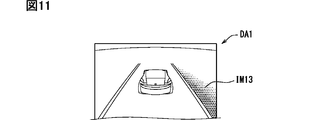
- the display example of FIG. 11 related to the display area DA1 is an example in the case of another vehicle approaching from behind in the lane to the right of the traveling lane in which the vehicle 1 travels in the situation of FIG.
- the red attention image IM13 is displayed in the ambient lighting tone on the right side of the road image IM12.
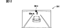
- the display example of FIG. 12 related to the display area DA1 is an example in the case where the route guidance of the car navigation is activated in the situation of FIG.
- a guide image IM14 including, for example, an arrow for guiding a left turn and a character "90 m ahead" is displayed.
- the mode of the host vehicle 1 is the auto cruise control mode
- the inter-vehicle distance to another vehicle in front is set, and the vehicle speed adjustment of the host vehicle 1 is automated.
- the other vehicle image IM15 corresponding to the other vehicle is displayed on the back side of the own vehicle image IM11.
- the display example of FIG. 14 related to the display areas DA2 and DA3 is an example in the case where an audio device separately mounted in the vehicle 1 is accepting a music selection operation.
- the icon corresponding to the audio device is displayed with higher brightness than other icons, and in the display area DA2, the image IM22 representing the information of the music being selected is displayed. ..
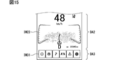
- the display example of FIG. 15 related to the display areas DA2 and DA3 is an example of the case where the route guidance of the car navigation is activated.
- the icon corresponding to the car navigation is displayed with higher brightness than other icons, and in the display area DA2, the image IM23 representing the map around the vehicle is displayed.
- the display surface 12 displays a plurality of icons (for example, the image IM31) representing various kinds of information in the frontmost display area DA3 among the plurality of display areas DA1, DA2, DA3.
- display contents for example, images IM21 and IM22
- a display area DA2 different from the display area on the front side.
- the concave curved portion 14 or the convex curved portion 15 is the convex curved portion 15 that is arranged on the innermost side
- the concave curved portion 14 and the convex curved portion 15 are provided. At least one of them may be provided in two or more.
- the display surface 12 has a plurality of concave curved portions 14 and a plurality of convex curved portions 15
- by arranging the concave curved portions 14 and the convex curved portions 15 alternately one by one In addition to the bird's-eye view, a wavy feeling can be generated.
- the curvature of the concave curved portion 14 and the curvature of the convex curved portion 15 may be different from each other.
- each curved portion 13 may be provided with a curvature also in the left-right direction orthogonal to the depth direction. Even in this case, each curved portion 13 can be regarded as a concave curved portion 14 as long as it is curved concavely on the cross section along the depth direction, and is curved convexly on the cross section along the depth direction. If so, it can be regarded as the convex curved portion 15.
- the display surface 12 may have a flat plane portion.
- a flat surface portion can be provided between the concave curved portion 14 and the convex curved portion 15 instead of the inflection point IP.
- a flat surface portion can be provided between the convex curved portion 15 arranged on the innermost side and the end portion 12b.
- a flat surface portion can be provided between the curved portion 13 and the end portion 12a arranged on the most front side.
- control device 40 does not have to be a device independent of the vehicle display device 10 and the HUD device 30, and is incorporated in the vehicle display device 10 or the HUD device 30. Good.
- any number can be set. It is also possible to set only one display area and display only one important display content on a large screen.
- the display surface 12 may have a touch panel function that receives a touch operation by the user. In that case, only the display area DA3 closest to the front may have the touch panel function.
- a combiner separate from the windshield 3 is installed, and light that can be formed as a virtual image VI is projected on the combiner, and this is a virtual image. You may make it function as the imaging part 3a.
- the display surface 12 and the virtual image forming unit 3a may have a left and right overlapping range, and the left and right positions may be slightly displaced.
- control unit and the method thereof described in the present disclosure are realized by a dedicated computer provided by configuring a processor and a memory programmed to execute one or more functions embodied by a computer program. May be done.
- control unit and the method thereof described in the present disclosure may be realized by a dedicated computer provided by configuring a processor with one or more dedicated hardware logic circuits.
- control unit and the method thereof described in the present disclosure are based on a combination of a processor and a memory programmed to execute one or a plurality of functions and a processor configured by one or more hardware logic circuits. It may be implemented by one or more dedicated computers configured.
- the computer program may be stored in a computer-readable non-transition tangible recording medium as an instruction executed by a computer.
- each section is expressed as, for example, S10. Further, each section can be divided into multiple subsections, while multiple sections can be combined into one section. Further, each section thus configured can be referred to as a device, module, means.
Landscapes
- Engineering & Computer Science (AREA)
- Chemical & Material Sciences (AREA)
- Combustion & Propulsion (AREA)
- Transportation (AREA)
- Mechanical Engineering (AREA)
- Instrument Panels (AREA)
Abstract
車両(1)用表示装置は、車両の前側から後ろ側へ向かう前後方向(DD)に曲率が設けられて湾曲する複数の湾曲部(13)を有し、上向きに実像(RI)を表示可能に形成された表示面(12)を備える。前記複数の湾曲部は、凹状に湾曲する凹状湾曲部(14)と、凸状に湾曲する凸状湾曲部(15)とを、互いに前記奥行方向にずれた部位に有する。前記凹状湾曲部及び前記凸状湾曲部のうち最も前側に配置されているのは、前記凸状湾曲部である。
Description
本出願は、2018年11月8日に出願された日本特許出願番号2018-210636号に基づくもので、ここにその記載内容を援用する。
本開示は、車両用表示装置及び車両用表示システムに関するものである。
従来、車両に設置されるように構成された車両用表示装置が知られている。特許文献1に開示の装置では、疑似的な曲面化を実現するために露出透光板に覆われた表示面が、直立して設置されている。また、露出透光板は、凹状に湾曲している。
特許文献1のように、表示面が直立した形態においては、使用者に対して鳥瞰感覚を発現させることができない。また、特許文献1のように、露出透光板を凹状に湾曲させると、その端部が切り立つような形状となるため、使用者に対して鳥瞰感覚を発現させることができない。このように、特許文献1の装置では、鳥瞰感覚が全く発現しないので、表示内容の把握し易さに、改善の余地が存在していた。
本開示は、使用者に対して鳥瞰感覚を発現させることによって、表示内容を把握し易くした車両用表示装置及び車両用表示システムを提供することを目的とする。
本開示のある態様にしたがって、車両に設置されるように構成された車両用表示装置は、車両の前側から後ろ側へ向かう前後方向に曲率が設けられて湾曲する複数の湾曲部を有し、上向きに実像を表示可能に形成された表示面を備える。前記複数の湾曲部は、凹状に湾曲する凹状湾曲部と、凸状に湾曲する凸状湾曲部とを、互いに前記奥行方向にずれた部位に有する。前記凹状湾曲部及び前記凸状湾曲部のうち最も前側に配置されているのは、前記凸状湾曲部である。
このような態様によると、上向きに実像を表示可能に形成された表示面において、凹状湾曲部及び凸状湾曲部が設けられている。湾曲形態の異なる凹状湾曲部及び凸状湾曲部が奥行方向にずれた部位に配置されることによって、高低感が生じた表示面による表示を、使用者は見下ろすように視認可能となる。
そして、凹状湾曲部及び凸状湾曲部のうち最も奥側に配置されているのは、凸状湾曲部であるため、表示面のうち奥側の部位が切り立つようになることが抑制され、水平方向への拡がり感を生じさせることができる。
以上により、使用者に対して鳥瞰感覚が発現されることによって、表示面の表示内容の把握を容易にすることができる。
本開示のある態様にしたがって、車両に搭載されるように構成された車両用表示システムは、虚像として結像されることが可能な表示光を、前記車両に設置された虚像結像部に投影するヘッドアップディスプレイ装置と、車両の後ろ側から前側へ向かう前後方向に曲率が設けられて湾曲する複数の湾曲部を有し、上向きに実像を表示する表示面と、を備える。前記湾曲部は、凹状に湾曲する凹状湾曲部と、凸状に湾曲する凸状湾曲部とを、互いに前記前後方向にずれた部位に有する。前記凹状湾曲部及び前記凸状湾曲部のうち最も前側に配置されているのは、前記凸状湾曲部である。前記表示面の最も前側の端部は、前記実像が前記虚像よりも後ろ側に表示されるように、前記虚像結像部に対して配置されている。
このような態様によると、上向きに実像を表示可能に形成された表示面において、凹状湾曲部及び凸状湾曲部が設けられている。湾曲形態の異なる凹状湾曲部及び凸状湾曲部が奥行方向にずれた部位に配置されることによって、高低感が生じた表示面による表示を、使用者は見下ろすように視認可能となる。
そして、凹状湾曲部及び凸状湾曲部のうち最も奥側に配置されているのは、凸状湾曲部であるため、表示面のうち奥側の部位が切り立つようになることが抑制され、水平方向への拡がり感を生じさせることができる。
さらには、表示面の最も奥側の端部と、ヘッドアップディスプレイ装置の表示光が投影された虚像結像部との位置関係に基づいて、実像が虚像結像部を用いて結像された虚像よりも手前側に表示されることによって、実像と虚像との間で、連続感ある表示が可能となる。すなわち、実像表示の奥行方向への拡がり感が顕著となる。
以上により、使用者に対して鳥瞰感覚が発現されることによって、表示面の表示内容の把握を容易にすることができる。
本開示についての上記目的およびその他の目的、特徴や利点は、添付の図面を参照しながら下記の詳細な記述により、より明確になる。その図面は、
第1実施形態における車両用表示システムの車両への搭載状態を示す斜視図であり、
第1実施形態における車両用表示システムの概略的構成をしめすブロック図であり、
第1実施形態における車両用表示システムの奥行方向及び鉛直面を含む断面を示す断面図であり、
表示面の湾曲形態を説明するための模式図であり、
表示面の湾曲形態及び複数の表示領域を説明するための図であり、
第1実施形態における表示例を示す図であり、
第1実施形態の車両用表示システムによるフローチャートであり、
比較例における図1に対応する図であり、
第2実施形態における車両用表示システムの車両への搭載状態を示す斜視図であり、
第2実施形態による表示例を示す図であり、
第2実施形態による他の表示例を示す図であり、
第2実施形態による他の表示例を示す図であり、
第2実施形態による他の表示例を示す図であり、
第2実施形態による他の表示例を示す図であり、
第2実施形態による他の表示例を示す図である。
以下、複数の実施形態を図面に基づいて説明する。なお、各実施形態において対応する構成要素には同一の符号を付すことにより、重複する説明を省略する場合がある。各実施形態において構成の一部分のみを説明している場合、当該構成の他の部分については、先行して説明した他の実施形態の構成を適用することができる。また、各実施形態の説明において明示している構成の組み合わせばかりではなく、特に組み合わせに支障が生じなければ、明示していなくても複数の実施形態の構成同士を部分的に組み合せることができる。
(第1実施形態)
本開示の第1実施形態による車両用表示装置10は、図1に示すように、車両1のインストルメントパネル2に設置されるように構成されている。図2に示すように、車両用表示装置10は、ヘッドアップディスプレイ装置(以下、HUD装置)30及び制御装置40等と共に、車両用表示システム100を構成している。車両用表示装置10は、インストルメントパネル2のうち、車両用表示システム100の使用者としての運転者が着座する運転席と前後に対向する運転席対向部に設置されている。
本開示の第1実施形態による車両用表示装置10は、図1に示すように、車両1のインストルメントパネル2に設置されるように構成されている。図2に示すように、車両用表示装置10は、ヘッドアップディスプレイ装置(以下、HUD装置)30及び制御装置40等と共に、車両用表示システム100を構成している。車両用表示装置10は、インストルメントパネル2のうち、車両用表示システム100の使用者としての運転者が着座する運転席と前後に対向する運転席対向部に設置されている。
なお、本実施形態において、上、下、前、後、左及び右の方向は、水平面HPが保たれた路面上の車両1を基準として定義される。なお、車両1を、他車両と区別する必要がある場合に、便宜上「自車両」と記載することがある。
図1に示すように、インストルメントパネル2よりも上方には、車両1のウインドシールド3が配置されている。ウインドシールド3は、例えばガラスないしは合成樹脂により透光性の板状に形成され、インストルメントパネル2よりも上方に配置されている。ウインドシールド3は、前方から後方へ向かう程、インストルメントパネル2とは離間するように傾斜して配置されている。
車両用表示装置10は、いわゆるグラフィックメータであり、画像表示パネル11、枠部18及びアンビエント照明部21を有している。画像表示パネル11は、薄板状に形成された曲面パネルとなっている。より詳細に、画像表示パネル11は、エレクトロルミネッセンスを用いて自発光可能な画素を2次元に配列してなり、輪郭が矩形状の表示面12を有するELパネルとなっている。この自発光には、有機エレクトロルミネッセンスないしは無機エレクトロルミネッセンスを用いることができる。
表示面12は、インストルメントパネル2の上部に露出して設けられることによって、上向きに実像RIを表示可能に形成されている。表示面12は、スキーのジャンプ台のような曲面状に形成されている。運転者が着座する座席を基準として手前側から奥側へ向かう方向を、奥行方向DDと定義すると、図3に示すように、矩形状の表示面12は、その長手方向を奥行方向DDに合わせて配置されている。なお、本実施形態では、インストルメントパネル2と座席とが前後に対向しているので、奥行方向DDは、車両1の前後方向に沿って規定することができる。
また、表示面12は、当該奥行方向DDに曲率が設けられて湾曲する複数の湾曲部13を有している。換言すると、湾曲部13は、奥行方向DDと鉛直面とを含む断面上において、0ではない曲率が設定されて湾曲している。ここで、本実施形態における複数の湾曲部13としては、1つの凹状湾曲部14と、1つの凸状湾曲部15とが、表示面12において互いに奥行方向DDにずれた部位に設けられている。
凹状湾曲部14は、凸状湾曲部15よりも手前側に配置されている。凹状湾曲部14は、凹状に湾曲し、より詳細には、奥行方向DDに直交する左右方向に母線が延伸する円筒面状に形成されている。
凸状湾曲部15は、凹状湾曲部14よりも奥側に配置されている。凸状湾曲部15は、凸状に湾曲し、より詳細には、左右方向に母線が延伸する円筒面状に形成されている。
このように、複数の湾曲部13のうち、最も奥側に配置されているのは、凹状湾曲部14ではなく、凸状湾曲部15となっている。また、図4に示すように、本実施形態では、凹状湾曲部14における曲率と、凸状湾曲部15における曲率とは、実質的に一致している。
本実施形態では、表示面12に平面部が設けられていない。すなわち、表示面12は、1つの凹状湾曲部14及び1つの凸状湾曲部15により全領域を占有されており、表示面12の全ての部位が曲率をもった形状となっている。すなわち、表示面12全体がS字状となっている。
したがって、凹状湾曲部14は、表示面12のうち最も手前側の端部12aまで達している。凹状湾曲部14は、当該凹状湾曲部14のうち、手前側を向くような傾斜状態を呈する奥側部位から、手前側部位へ向かう程、より水平面HPに近づくように形成されている。ただし、表示面12のうち最も手前側の端部12aにおいても、水平状態までは達しておらず、若干の勾配を残していることで、手前側を僅かに向くような傾斜状態が保たれている。
また、凸状湾曲部15は、表示面12のうち最も奥側の端部12bまで達している。凸状湾曲部15は、当該凸状湾曲部15のうち、手前側を向くような傾斜状態を呈する手前側部位から、奥側部位へ向かう程、より水平面HPに近づくように形成されている。ただし、表示面12のうち最も奥側の端部12bにおいても、水平状態までは達しておらず、若干の勾配を残していることで、手前側を僅かに向くような傾斜状態が保たれている。
そして、凹状湾曲部14と凸状湾曲部15とは、湾曲方向が変わる変曲点IPを介して、直接的に滑らかに接続されている。ここでいう滑らかとは、曲率及び曲率の1次微分に連続性があることをいう。なお、変曲点IPは、便宜上「点」と表現しているが、表示面12が左右方向に幅を持っているため、厳密には、「線」状に設定されており、こうした概念を含むように広義的に解することができる。この変曲点IPでの表示面12の勾配は、表示面12における各部位の勾配中、最大となっている。変曲点IPにおいても、表示面12は、真横を向くわけではなく、上向き成分を有して傾斜状態が保たれている。
この変曲点IPから手前側又は奥側へ向かう程、表示面12の勾配が漸次小さくなり、上述のように水平面HPへ近づく形態となっている。このようにして、表示面12には、手前側から奥側へ向かう程、上方へせり上がるような高低差が生じている。
なお、画像表示パネル11としては、曲面状の表示面12を実現可能であれば、ELパネル以外の液晶パネル等が採用されていてもよい。
枠部18は、例えば合成樹脂により暗色(例えば黒色)に形成され、画像表示パネル11の表示面12の全周を囲む枠状を呈している。枠部18は、表示面12の最も奥側の端部12bからさらに奥側に、表示面12に連続するように延伸する非表示延伸面19を有している。非表示延伸面19は、表示不能かつ平面状に形成されている。
図1に示すアンビエント照明部21は、装置10の左右方向を向く側壁部に設けられている。換言すると、アンビエント照明部21は、表示面12を挟む両側に設けられている。アンビエント照明部21は、例えば複数の発光ダイオード素子を奥行方向DDに配列して設けられ、表示面12の周囲を照明する。
HUD装置30は、図2,3に示すように、車両1のインストルメントパネル2に設置されるように構成されている。HUD装置30は、車両1のウインドシールド3において平面状又は凹面状に形成された虚像結像部3aへ向けて表示光を投影する。すなわち、虚像結像部3aにて反射された表示光を、座席に着座する運転者は、結像された虚像VIとして知覚することが可能である。HUD装置30は、表示器31及び反射鏡32等により構成されている。表示器31及び反射鏡32等は、遮光性を有するハウジングの内部に収容されている。
表示器31は、画像を表示し、その表示光を発する。表示器31としては、バックライトを用いた液晶方式の表示器、エレクトロルミネッセンスを用いて自発光するELパネルを用いた表示器、レーザスキャナ方式の表示器、DMD(Digital Micromirror Device)を用いたDLP(Digital Light Processing;登録商標)方式の表示器等を採用することができる。
反射鏡32は、例えば合成樹脂ないしはガラスの表面にアルミニウム等の金属膜を蒸着させること等により形成されている。反射鏡32は、凹面状又は平面状の反射面を有している。反射鏡32は、表示器31から発せられた表示光を、反射面により虚像結像部3aへ向けて反射する。ここで、ハウジングの上面及びインストルメントパネル2の上面には、窓部33が設けられており、反射鏡32に反射された表示光は、窓部33を通過して虚像結像部3aへと到達するようになっている。窓部33は、開口穴が形成されて機械的に開口していてもよく、透光性又は半透光性を有する防塵シート等により塞がれることによって光学的に開口していてもよい。
本実施形態では、例えば非表示延伸面19の一部がスモーク調の着色により半透光性を有する防塵シートによって形成されていることで、窓部33が設けられている。これにより、虚像結像部3aは、表示面12の端部12bの近傍に設定されることができ、虚像結像部3aの左右方向の位置と表示面12の左右方向の位置とを、容易に合わせることができる。そして、表示面12に表示される実像RIは、虚像VIよりも手前側に表示される。
制御装置40は、図2に示すように、いわゆるコンピュータであり、少なくとも1つのプロセッサ、メモリ装置、入出力インターフェースを含む電子回路を主体として構成されている。プロセッサは、メモリ装置に記憶されているコンピュータプログラムを実行する演算回路である。メモリ装置は、例えば半導体メモリによって提供され、プロセッサによって読み取り可能なコンピュータプログラム及びデータを非一時的に格納するための記憶媒体である。
制御装置40は、車両用表示装置10の画像表示パネル11、及びHUD装置30の表示器31と通信可能に接続されており、画像表示パネル11が表示面12に表示する実像RI及び表示器31を用いて表示される虚像VIを制御する。加えて、制御装置40は、通信を用いた電気信号の入力によって、車両1からの各種情報を取得可能に構成されている。
制御装置40は、機能ブロックとして、表示領域設定部41及び表示内容割当部42を有している。表示領域設定部41は、表示面12に表示される実像RI及び虚像結像部3aを介して表示される虚像VIについて、複数の表示領域DA1,DA2,DA3を設定する。複数の表示領域DA1,DA2,DA3は、互いに奥行方向DDに分割されたように配置される。具体的に図5に示すように、表示領域設定部41は、実像RIのうち最も表示面12の奥側の領域及び虚像VIのうち全領域を、1つの表示領域DA1に設定する。また、表示領域設定部41は、実像RIのうち表示領域DA1に設定されなかった部分であって、奥側の領域を、表示領域DA2に設定する。また、表示領域設定部41は、実像RIのうち表示領域DA1に設定されなかった部分であって、手前側の領域(すなわち表示領域DA2にも設定されなかった領域)を、表示領域DA3に設定する。
こうして設定された表示領域DA3は、凹状湾曲部14のうち手前側の一部分に対応している。表示領域DA2は、凹状湾曲部14のうち奥側の一部分と、変曲点IPを挟んだ凸状湾曲部15のうち手前側の一部分とに対応している。表示領域DA3のうち実像RIの領域は、凸状湾曲部15のうち奥側の一部分に対応している。
係る対応関係と、上述の高低差とにより、表示領域DA1は、運転者に対して最も視距離が遠く、俯角が小さな遠距離かつ小俯角の領域となっている。一方、表示領域DA3は、運転者に対して最も視距離が近く、俯角が大きな近距離かつ大俯角の領域となっている。表示領域DA1と表示領域DA3との間に配置された表示領域DA2は、中距離かつ中俯角の領域となっている。なお、図5において楕円状の領域(アイリプスともいう)が運転者のアイポイントとして想定されている。
表示内容割当部42は、車両1から取得された各種情報を整理し、複数の表示領域DA1,DA2,DA3が互いに異なる表示内容を表示するように、表示内容を割り当てる。表示領域DA1には、ウインドシールド3を通して前景を視認しながら運転をしている運転者に対して、気付かせることが必要な表示内容が割り当てられる。例えば、車両1の運転において重要性が高い車速等の表示内容や、車両1の外部の監視状態の表示内容等が割り当てられる。
表示領域DA3には、運転者が意識して見に行く表示内容が割り当てられる。例えば、ガジェット等が表示される。
表示領域DA2には、表示領域DA1に割り当てられる表示内容と、表示領域DA2に割り当てられる表示内容との中間の属性を有する表示内容が割り当てられる。例えば、車両1の状態(燃料又は電池残量、オド値、シフトレンジ等)の表示内容等が割り当てられる。
特に本実施形態では、表示内容割当部42は、複数の表示領域DA1,DA2,DA3のうち奥側の表示領域である程、表示する表示内容の情報量が少なくなるように、表示内容を割り当てる。すなわち、表示領域DA1の情報量が最も少なく、表示領域DA3の情報量が最も多くなる。
ここで、本実施形態における情報量としては、情報の項目数、情報の詳細さ、又は情報を表示するための文字数(マークも含む)といった指標が挙げられる。情報量の比較に関しては、ここで挙げた指標のうちいずれか1つの指標を比較し、各表示領域DA1,DA2,DA3の情報量の関係が成立するようにする。
ここで、表示領域DA1における表示例を図6を用いて説明する。この表示例は、自車両1のモードがオートクルーズコントロールモードであり、前方の他車両に対する車間距離を設定して、自車両1の車速の調整を自動化している場合の例である。表示領域DA1のうち、実像RI側の領域には、自車両1に対応する自車両画像IM1が表示される。
表示領域DA1のうち、虚像VI側の領域には、自車両1に対して前方に位置する他車両に対応する他車両画像IM2が表示される。この他車両画像IM2の表示の有無によって、運転者に対して、前方に他車両が存在するか否かを把握させることができる。また、虚像VI側の領域のうち他車両画像IM2と離れた位置に、自車両1の車速が表示される。
そして、自車両画像IM1と他車両画像IM2との間には、道路に対応する道路画像IM3が実像RI及び虚像VIを跨ぐように表示される。この道路画像IM3により、運転者に対して、車間距離や道路の線形を把握させることが可能となる。また、この道路画像IM3により、実像RIと虚像VIとの間を跨ぐように共通の表示内容が表示されることとなり、実像RI及び虚像VIに連続性及び一体感を生じさせることができる。
以下、第1実施形態の車両用表示システム100により実行される処理について、図7のフローチャートを用いて説明する。
ステップS10では、表示領域設定部41が、複数の表示領域DA1,DA2,DA3を設定する。ステップS10の処理後、ステップS20へ移る。
ステップS20では、表示内容割当部42が、各表示領域DA1,DA2,DA3に表示内容を割り当てる。ステップS20の処理後、ステップS30へ移る。
ステップS30では、表示内容割当部42が割り当てた表示内容に基づいて、実像RI及び虚像VIが表示される。ステップS30の処理によって、表示内容が運転者に対して提供される。
(作用効果)
以上説明した第1実施形態の作用効果を以下に改めて説明する。
以上説明した第1実施形態の作用効果を以下に改めて説明する。
第1実施形態の車両用表示装置10によると、上向きに実像RIを表示可能に形成された表示面12において、凹状湾曲部14及び凸状湾曲部15が設けられている。湾曲形態の異なる凹状湾曲部14及び凸状湾曲部15が奥行方向DDにずれた部位に配置されることによって、高低感が生じた表示面12による表示を、使用者としての運転者は見下ろすように視認可能となる。
そして、凹状湾曲部14及び凸状湾曲部15のうち最も奥側に配置されているのは、凸状湾曲部15であるため、表示面12のうち奥側の部位が切り立つようになることが抑制され、水平方向への拡がり感を生じさせることができる。
以上により、運転者に対して鳥瞰感覚が発現されることによって、表示面12の表示内容の把握を容易にすることができる。
また、第1実施形態によると、表示面12の最も奥側の端部12bと、虚像結像部3aとの位置関係に基づいて、実像RIが虚像VIよりも手前側に表示されることによって、実像RIと虚像VIとの間で、連続感ある表示が可能となる。すなわち、実像表示の奥行方向DDへの拡がり感が顕著となるので、運転者に対する鳥瞰感覚の発現効果は、より高いものとなる。
また、第1実施形態によると、最も奥側に配置された凸状湾曲部15は、表示面12の最も奥側の端部12bまで達している。このようにすると、表示面12の面積を十分に活用して、凸状の湾曲形状を形成できる。すなわち、表示面12に高低差を付与するための湾曲を広い面積に分散させることで、局所的に曲率が大きな部位が表示面12に発生することを抑制し、実像RIの視認性を高めることができる。
また、第1実施形態によると、最も奥側に配置された凸状湾曲部15は、手前側を向くような傾斜状態を呈する手前側部位から、奥側部位へ向かう程、より水平面HPに近づくように形成されている。これにより、表示面12の奥側における水平方向への拡がり感を高めることができ、鳥瞰感覚の発現効果は、際立ったものとなる。
また、第1実施形態によると、凹状湾曲部14と凸状湾曲部15とは、湾曲方向が変わる変曲点IPを介して接続されている。このようにすると、凹状湾曲部14と凸状湾曲部15との一体感及び連続感が生じるため、表示面12がシームレスに拡がる印象を付与することができ、これにより、拡がり感が向上する。これと共に、表示面12の面積を十分に活用して、凸状の湾曲形状を形成できる。すなわち、表示面12に高低差を付与するための湾曲を広い面積に分散させることで、局所的に曲率が大きな部位が表示面12に発生することを抑制し、実像RIの視認性を高めることができる。
また、第1実施形態によると、湾曲部13は、円筒面状に形成されている。円筒面状の湾曲部13によれば、表示面12に高低差を付与しつつも、高低差を生じさせた奥行方向DDと交差する方向では、平面的な拡がり感を演出することができる。故に、鳥瞰感覚の発現効果を高めることができる。
また、第1実施形態によると、凹状湾曲部14と凸状湾曲部15とが一対設けられることにより、表示面12は、S字状に湾曲している。S字状の湾曲では、奥行方向DDで湾曲形態が目まぐるしく変化することが抑制できるので、煩雑な印象を抑制して、拡がり感を演出することができる。
また、第1実施形態によると、非表示延伸面19は、表示面12の最も奥側の端部12bよりもさらに奥側に延伸するように配置され、表示不能かつ平面状に形成されている。表示面12の最も奥側の端部12bから非表示延伸面19がさらに平面状に延伸することによって、表示面12を越えた外部にも奥行方向DDへの拡がり感を波及させることができる。
また、第1実施形態によると、表示面12は、奥行方向DDに分割され、互いに異なる表示内容を表示する複数の表示領域DA1,DA2,DA3を有する。このようにすると、運転者の俯角に応じて異なる表示内容が表示されるようになる。すなわち、運転者は、把握したい表示内容を、俯角を変えることによって選択することができるので、表示内容の把握は一層容易となる。
また、第1実施形態によると、複数の表示領域DA1,DA2,DA3のうち奥側の表示領域である程、表示する表示内容の情報量が少ない。一般的な鳥瞰図は、手前側に詳細な町並み等が描かれ、奥側に向かう程、山、空が描かれて情報量が少なくなっていくものであるから、本実施形態のように情報量を奥側ほど少なく制御することによって、鳥瞰感覚の発現効果は、極めて顕著なものとなる。また、奥側の表示領域である程、俯角が小さい状態で視認できるため、運転者が運転中に視認容易であるから、奥側の表示領域DA1の情報量を厳選することによって、運転者を運転に集中させつつ、表示内容を把握し易くすることができる。
また、第1実施形態の車両用表示システム100によると、上向きに実像RIを表示可能に形成された表示面12において、凹状湾曲部14及び凸状湾曲部15が設けられている。湾曲形態の異なる凹状湾曲部14及び凸状湾曲部15が奥行方向DDにずれた部位に配置されることによって、高低感が生じた表示面12による表示を、運転者は見下ろすように視認可能となる。
そして、凹状湾曲部14及び凸状湾曲部15のうち最も奥側に配置されているのは、凸状湾曲部15であるため、表示面12のうち奥側の部位が切り立つようになることが抑制され、水平方向への拡がり感を生じさせることができる。
さらには、表示面12の最も奥側の端部12bと、HUD装置30の表示光が投影される虚像結像部3aとの位置関係に基づいて、実像RIが虚像結像部3aを用いて結像された虚像VIよりも手前側に表示されることによって、実像RIと虚像VIとの間で、連続感ある表示が可能となる。すなわち、実像表示の奥行方向への拡がり感が顕著となる。
以上により、運転者に対して鳥瞰感覚が発現されることによって、表示面12の表示内容の把握を容易にすることができる。
また、第1実施形態によると、制御装置40は、表示面12に表示される実像RIと、表示光により結像される虚像VIとの間を跨ぐように、共通の表示内容を表示させる。実像RIと虚像VIとを跨ぐ共通の表示内容から生まれる連続感によって、表示面12を越えた外部へ拡がり感を波及させることができるので、鳥瞰感覚の発現効果を高めることができる。
第1実施形態の車両用表示システム100における鳥瞰感覚の発現は、図8に示す比較例との対比によってより一層明確に理解することができる。比較例の表示面912は、第1実施形態と同様に、湾曲部913として、一対の凹状湾曲部914及び凸状湾曲部915を有しているが、凹状湾曲部914及び凸状湾曲部915のうち、最も奥側に配置されているのは、凹状湾曲部914である。
このようにすると、表示面912の手前側の端部912aについては大きな問題はないものの、表示面912の奥側の端部912bが立ち上がり、切り立つような形状となる。このため、水平方向への拡がり感を生じさせることは困難となる。特に、表示面912の実像RIに対して虚像VIが連続的に表示されると、虚像VI自体が直立してしまう。最も奥側の表示領域DA1が立ち上がったように視認されるため、水平方向への拡がり感を生じさせることは極めて難しくなる。
(第2実施形態)
図9~15に示すように、第2実施形態は第1実施形態の変形例である。第2実施形態について、第1実施形態とは異なる点を中心に説明する。
図9~15に示すように、第2実施形態は第1実施形態の変形例である。第2実施形態について、第1実施形態とは異なる点を中心に説明する。
第2実施形態の車両用表示システム200には、図9に示すように、HUD装置が設けられておらず、車両用表示装置210及び制御装置40等により構成されている。
車両用表示装置210において、表示面12の曲面形態は、第1実施形態と同様になっている。ただし、本実施形態の車両用表示装置210では、表示面12とウインドシールドとの間に、フード223が設けられている。フード223は、例えば合成樹脂により、遮光性に形成され、ウインドシールドを介して外光が表示面12に入射することを抑制し、表示面12による実像RIの見易さを改善する。なお、フード223は、半透光性に形成されていてもよいが、遮光性である方がより効果的である。
第2実施形態の制御装置40において表示領域設定部41は、表示面12に表示される実像RIについて、複数の表示領域DA1,DA2,DA3を設定する。具体的に、表示領域設定部41は、実像RIのうち最も表示面12の奥側の領域を、表示領域DA1に設定する。表示領域DA2,DA3は、第1実施形態と同様である。
ここで、各表示領域DA1,DA2,DA3における表示例を図10~15を用いて説明する。図10の表示例は、車両1のモードが標準モードにおける表示例である。表示領域DA1には、自車両1に対応する自車両画像IM11及び道路に対応する道路画像IM12が表示される。表示領域DA2には、車両1の状態を表す画像IM21が表示される。表示領域DA3には、車両1のモード等の設定状態を表すアイコン、オーディオ機器、カーナビゲーション等の作動状態を表すアイコン等が左右に並ぶ画像IM31が表示される。
表示領域DA1に係る図11の表示例は、図10の状況において、自車両1が走行する走行車線の右隣りの車線において、後方から他車両が接近している場合における例である。この場合には、道路画像IM12の右隣に、赤色の注意喚起画像IM13がアンビエント照明調に表示される。
表示領域DA1に係る図12の表示例は、図10の状況において、カーナビゲーションの経路誘導を作動させている場合における例である。この場合には、例えば左折を案内する矢印と、「90m先」の文字とからなる誘導画像IM14が表示される。
表示領域DA1に係る図13の表示例は、自車両1のモードがオートクルーズコントロールモードであり、前方の他車両に対する車間距離を設定して、自車両1の車速の調整を自動化している場合の例である。この場合は、自車両画像IM11よりも奥側に他車両に対応する他車両画像IM15が表示される。
表示領域DA2,DA3に係る図14の表示例は、車両1に別途搭載されたオーディオ機器において、選曲操作を受け付けている場合の例である。この場合、表示領域DA3の画像IM31において、オーディオ機器に対応するアイコンが他のアイコンよりも高輝度で表示されると共に、表示領域DA2に、選曲中の音楽の情報を表す画像IM22が表示される。
表示領域DA2,DA3に係る図15の表示例は、カーナビゲーションの経路誘導を作動させている場合の例である。この場合、表示領域DA3の画像IM31において、カーナビゲーションに対応するアイコンが他のアイコンよりも高輝度で表示されると共に、表示領域DA2に、車両周辺の地図を表す画像IM23が表示される。
以上説明した第2実施形態によると、表示面12は、複数の表示領域DA1,DA2,DA3のうち最も手前側の表示領域DA3に、各種情報を表す複数のアイコン(例えば画像IM31)を表示すると共に、最も手前側の表示領域とは別の表示領域DA2に、複数のアイコンを具体化した表示内容(例えば画像IM21,IM22)を表示する。このようにすると、運転者は、具体化した表示内容を、必要以上に俯角を下げないで視認することができ、かつ、運転中に前景を見ている状態から当該具体化した表示内容を見に行く視線移動の過程において、煩雑な複数のアイコンを見なくても済むので、表示内容の把握が容易となる。
(他の実施形態)
以上、複数の実施形態について説明したが、本開示は、それらの実施形態に限定して解釈されるものではなく、本開示の要旨を逸脱しない範囲内において種々の実施形態及び組み合わせに適用することができる。
以上、複数の実施形態について説明したが、本開示は、それらの実施形態に限定して解釈されるものではなく、本開示の要旨を逸脱しない範囲内において種々の実施形態及び組み合わせに適用することができる。
具体的に変形例1としては、凹状湾曲部14及び凸状湾曲部15のうち最も奥側に配置されているのが凸状湾曲部15であれば、凹状湾曲部14及び凸状湾曲部15うち少なくとも一方は、2つ以上設けられていてもよい。例えば、表示面12が複数の凹状湾曲部14及び複数の凸状湾曲部15を有する形態において、凹状湾曲部14と凸状湾曲部15とを、1つずつ交互に配列していくことによって、鳥瞰感覚に加えて、波状感を生じさせることができる。
変形例2としては,凹状湾曲部14の曲率と凸状湾曲部15の曲率とは、互いに異なっていてもよい。
変形例3としては、各湾曲部13は、奥行方向に直交する左右方向にも曲率が設けられていてもよい。この場合であっても、各湾曲部13を、奥行方向に沿った断面上において凹状に湾曲していれば凹状湾曲部14とみなすことができ、奥行方向に沿った断面上において凸状に湾曲していれば凸状湾曲部15とみなすことができる。
変形例4としては、表示面12は、平面状の平面部を有していてもよい。例えば、凹状湾曲部14と凸状湾曲部15との間に、変曲点IPの代わりに、平面部を設けることができる。また、最も奥側に配置された凸状湾曲部15と端部12bとの間に、平面部を設けることができる。また、最も手前側に配置された湾曲部13と端部12aとの間に、平面部を設けることができる。
変形例5としては、制御装置40は、車両用表示装置10及びHUD装置30に対して独立した装置になっていなくてもよく、車両用表示装置10又はHUD装置30の内部に組み込まれていてもよい。
変形例6としては、互いに異なる表示内容を表示する表示領域は、2つ以上であれば、任意の数設定することができる。また、表示領域を、1つだけ設定して、重要な表示内容を大画面で1つだけ表示することも可能である。
変形例7としては、表示面12は、使用者による接触操作を受け付けるタッチパネル機能を有していてもよい。その場合、最も手前側の表示領域DA3だけにタッチパネル機能を持たせてもよい。
第1実施形態に関する変形例8としては、ウインドシールド3とは別体のコンバイナを設置し、当該コンバイナに虚像VIとして結像されることが可能な光が投影されるようにして、これを虚像結像部3aとして機能させてもよい。
第1実施形態に関する変形例9としては、表示面12と虚像結像部3aとは、左右に重複範囲を有していればよく、左右の位置が少しずれていてもよい。
本開示に記載の制御部及びその手法は、コンピュータプログラムにより具体化された一つ乃至は複数の機能を実行するようにプログラムされたプロセッサ及びメモリーを構成することによって提供された専用コンピュータにより、実現されてもよい。あるいは、本開示に記載の制御部及びその手法は、一つ以上の専用ハードウエア論理回路によってプロセッサを構成することによって提供された専用コンピュータにより、実現されてもよい。もしくは、本開示に記載の制御部及びその手法は、一つ乃至は複数の機能を実行するようにプログラムされたプロセッサ及びメモリーと一つ以上のハードウエア論理回路によって構成されたプロセッサとの組み合わせにより構成された一つ以上の専用コンピュータにより、実現されてもよい。また、コンピュータプログラムは、コンピュータにより実行されるインストラクションとして、コンピュータ読み取り可能な非遷移有形記録媒体に記憶されていてもよい。
ここで、この出願に記載されるフローチャート、あるいは、フローチャートの処理は、複数のセクション(あるいはステップと言及される)から構成され、各セクションは、たとえば、S10と表現される。さらに、各セクションは、複数のサブセクションに分割されることができる、一方、複数のセクションが合わさって一つのセクションにすることも可能である。さらに、このように構成される各セクションは、デバイス、モジュール、ミーンズとして言及されることができる。
本開示は、実施例に準拠して記述されたが、本開示は当該実施例や構造に限定されるものではないと理解される。本開示は、様々な変形例や均等範囲内の変形をも包含する。加えて、様々な組み合わせや形態、さらには、それらに一要素のみ、それ以上、あるいはそれ以下、を含む他の組み合わせや形態をも、本開示の範疇や思想範囲に入るものである。
Claims (13)
- 車両(1)に設置されるように構成された車両用表示装置であって、
車両の前側から後ろ側へ向かう前後方向(DD)に曲率が設けられて湾曲する複数の湾曲部(13)を有し、上向きに実像(RI)を表示可能に形成された表示面(12)を備え、
前記複数の湾曲部は、凹状に湾曲する凹状湾曲部(14)と、凸状に湾曲する凸状湾曲部(15)とを、互いに前記奥行方向にずれた部位に有し、
前記凹状湾曲部及び前記凸状湾曲部のうち最も前側に配置されているのは、前記凸状湾曲部である車両用表示装置。 - 前記車両には、虚像(VI)として結像されることが可能な光が投影される虚像結像部(3a)が設けられ、
前記表示面の最も前側の端部(12b)は、前記実像が前記虚像よりも後ろ側に表示されるように、前記虚像結像部に対して配置されている請求項1に記載の車両用表示装置。 - 最も前側に配置された前記凸状湾曲部は、前記表示面の最も前側の端部まで達している請求項1又は2に記載の車両用表示装置。
- 最も前側に配置された前記凸状湾曲部は、後ろ側を向くような傾斜状態を呈する後ろ側部位から、前側部位へ向かう程、より水平面(HP)に近づくように形成されている請求項1から3のいずれか1項に記載の車両用表示装置。
- 前記凹状湾曲部と前記凸状湾曲部とは、湾曲方向が変わる変曲点(IP)を介して接続されている請求項1から4のいずれか1項に記載の車両用表示装置。
- 前記湾曲部は、円筒面状に形成されている請求項1から5のいずれか1項に記載の車両用表示装置。
- 前記凹状湾曲部と前記凸状湾曲部とが一対設けられることにより、前記表示面は、S字状に湾曲している請求項1から6のいずれか1項に記載の車両用表示装置。
- 前記表示面の最も前側の端部よりもさらに前側に延伸するように配置され、表示不能かつ平面状に形成された非表示延伸面(19)を、さらに備える請求項1から7のいずれか1項に記載の車両用表示装置。
- 前記表示面は、前記前後方向に分割され、互いに異なる表示内容を表示する複数の表示領域(DA1,DA2,DA3)を有する請求項1から8のいずれか1項に記載の車両用表示装置。
- 前記複数の表示領域のうち前側の表示領域である程、表示する前記表示内容の情報量が少ない請求項9に記載の車両用表示装置。
- 前記表示面は、前記複数の表示領域のうち最も後ろ側の表示領域(DA3)に、各種情報を表す複数のアイコンを表示すると共に、前記最も後ろ側の表示領域とは別の前記表示領域(DA2)に、前記複数のアイコンを具体化した前記表示内容を表示する請求項9又は10に記載の車両用表示装置。
- 車両(1)に搭載されるように構成された車両用表示システムであって、
虚像(VI)として結像されることが可能な表示光を、前記車両に設置された虚像結像部(3a)に投影するヘッドアップディスプレイ装置(30)と、
車両の後ろ側から前側へ向かう前後方向(DD)に曲率が設けられて湾曲する複数の湾曲部(13)を有し、上向きに実像(RI)を表示する表示面(12)と、を備え、
前記湾曲部は、凹状に湾曲する凹状湾曲部(14)と、凸状に湾曲する凸状湾曲部(15)とを、互いに前記前後方向にずれた部位に有し、
前記凹状湾曲部及び前記凸状湾曲部のうち最も前側に配置されているのは、前記凸状湾曲部(15)であり、
前記表示面の最も前側の端部(12b)は、前記実像が前記虚像よりも後ろ側に表示されるように、前記虚像結像部に対して配置されている車両用表示システム。 - 前記表示面に表示される前記実像と、前記表示光により結像される前記虚像との間を跨ぐように、共通の表示内容を表示させる制御装置(40)を、さらに備える請求項12に記載の車両用表示システム。
Applications Claiming Priority (2)
| Application Number | Priority Date | Filing Date | Title |
|---|---|---|---|
| JP2018210636A JP2020075643A (ja) | 2018-11-08 | 2018-11-08 | 車両用表示装置及び車両用表示システム |
| JP2018-210636 | 2018-11-08 |
Publications (1)
| Publication Number | Publication Date |
|---|---|
| WO2020095923A1 true WO2020095923A1 (ja) | 2020-05-14 |
Family
ID=70611809
Family Applications (1)
| Application Number | Title | Priority Date | Filing Date |
|---|---|---|---|
| PCT/JP2019/043389 Ceased WO2020095923A1 (ja) | 2018-11-08 | 2019-11-06 | 車両用表示装置及び車両用表示システム |
Country Status (2)
| Country | Link |
|---|---|
| JP (1) | JP2020075643A (ja) |
| WO (1) | WO2020095923A1 (ja) |
Families Citing this family (1)
| Publication number | Priority date | Publication date | Assignee | Title |
|---|---|---|---|---|
| JP7826864B2 (ja) * | 2022-06-27 | 2026-03-10 | 株式会社デンソー | 車載表示装置 |
Citations (5)
| Publication number | Priority date | Publication date | Assignee | Title |
|---|---|---|---|---|
| JP2012081780A (ja) * | 2010-10-07 | 2012-04-26 | Stanley Electric Co Ltd | ヘッドアップ表示灯 |
| JP2013088521A (ja) * | 2011-10-14 | 2013-05-13 | Denso Corp | ヘッドアップディスプレイ装置 |
| JP2016113151A (ja) * | 2014-12-16 | 2016-06-23 | 株式会社デンソー | ヘッドアップディスプレイ用カバー部材、および表示装置 |
| JP2016121890A (ja) * | 2014-12-24 | 2016-07-07 | 矢崎総業株式会社 | 表示装置 |
| JP2018112628A (ja) * | 2017-01-10 | 2018-07-19 | 株式会社デンソー | ヘッドアップディスプレイ装置 |
-
2018
- 2018-11-08 JP JP2018210636A patent/JP2020075643A/ja active Pending
-
2019
- 2019-11-06 WO PCT/JP2019/043389 patent/WO2020095923A1/ja not_active Ceased
Patent Citations (5)
| Publication number | Priority date | Publication date | Assignee | Title |
|---|---|---|---|---|
| JP2012081780A (ja) * | 2010-10-07 | 2012-04-26 | Stanley Electric Co Ltd | ヘッドアップ表示灯 |
| JP2013088521A (ja) * | 2011-10-14 | 2013-05-13 | Denso Corp | ヘッドアップディスプレイ装置 |
| JP2016113151A (ja) * | 2014-12-16 | 2016-06-23 | 株式会社デンソー | ヘッドアップディスプレイ用カバー部材、および表示装置 |
| JP2016121890A (ja) * | 2014-12-24 | 2016-07-07 | 矢崎総業株式会社 | 表示装置 |
| JP2018112628A (ja) * | 2017-01-10 | 2018-07-19 | 株式会社デンソー | ヘッドアップディスプレイ装置 |
Also Published As
| Publication number | Publication date |
|---|---|
| JP2020075643A (ja) | 2020-05-21 |
Similar Documents
| Publication | Publication Date | Title |
|---|---|---|
| JP6749981B2 (ja) | 表示装置、表示制御方法、およびプログラム | |
| KR20230034448A (ko) | 차량 및 그 제어 방법 | |
| EP3751329B1 (en) | Display device, method, head-up display system, transportation means, and storage medium | |
| US20170031162A1 (en) | Display device for vehicle and display method for vehicle | |
| JP2017072668A (ja) | 表示装置及び表示システム | |
| US20180144673A1 (en) | Multi-layer display system for vehicle dash or the like | |
| JP6136884B2 (ja) | 車両用表示装置 | |
| JPWO2018159319A1 (ja) | ヘッドアップディスプレイ装置及び車載表示システム | |
| JP5659679B2 (ja) | 表示装置 | |
| JP7110968B2 (ja) | ヘッドアップディスプレイ装置 | |
| JP2020056887A (ja) | 表示装置、表示制御方法、およびプログラム | |
| JP2020112667A (ja) | 虚像表示装置 | |
| US20190235290A1 (en) | Display device | |
| CN110816269B (zh) | 显示装置、显示控制方法及存储介质 | |
| JP2020098270A (ja) | 虚像表示装置 | |
| JP2009080178A (ja) | ヘッドアップディスプレイ | |
| US20260110901A1 (en) | Personalized infotainment device for vehicle | |
| JP2020067461A (ja) | 表示装置 | |
| CN112313737B (zh) | 影像显示装置 | |
| WO2020095923A1 (ja) | 車両用表示装置及び車両用表示システム | |
| JP6780960B2 (ja) | 画像表示装置 | |
| JP6579169B2 (ja) | 表示装置 | |
| JP6885215B2 (ja) | 表示装置 | |
| JP2018077455A5 (ja) | ||
| JP2021051231A (ja) | ヘッドアップディスプレイ装置 |
Legal Events
| Date | Code | Title | Description |
|---|---|---|---|
| 121 | Ep: the epo has been informed by wipo that ep was designated in this application |
Ref document number: 19883061 Country of ref document: EP Kind code of ref document: A1 |
|
| NENP | Non-entry into the national phase |
Ref country code: DE |
|
| 122 | Ep: pct application non-entry in european phase |
Ref document number: 19883061 Country of ref document: EP Kind code of ref document: A1 |