WO2020095569A1 - 粒子物性測定に用いられる光学測定用セル及びこれを用いた粒子物性測定装置 - Google Patents
粒子物性測定に用いられる光学測定用セル及びこれを用いた粒子物性測定装置 Download PDFInfo
- Publication number
- WO2020095569A1 WO2020095569A1 PCT/JP2019/038350 JP2019038350W WO2020095569A1 WO 2020095569 A1 WO2020095569 A1 WO 2020095569A1 JP 2019038350 W JP2019038350 W JP 2019038350W WO 2020095569 A1 WO2020095569 A1 WO 2020095569A1
- Authority
- WO
- WIPO (PCT)
- Prior art keywords
- temperature control
- control fluid
- temperature
- measurement
- optical measurement
- Prior art date
- Legal status (The legal status is an assumption and is not a legal conclusion. Google has not performed a legal analysis and makes no representation as to the accuracy of the status listed.)
- Ceased
Links
- IQLVUZSISFSIGE-UHFFFAOYSA-N CCCC1CCN(CN)CCCC1 Chemical compound CCCC1CCN(CN)CCCC1 IQLVUZSISFSIGE-UHFFFAOYSA-N 0.000 description 1
Images







Classifications
-
- G—PHYSICS
- G01—MEASURING; TESTING
- G01N—INVESTIGATING OR ANALYSING MATERIALS BY DETERMINING THEIR CHEMICAL OR PHYSICAL PROPERTIES
- G01N15/00—Investigating characteristics of particles; Investigating permeability, pore-volume or surface-area of porous materials
- G01N15/02—Investigating particle size or size distribution
-
- G—PHYSICS
- G01—MEASURING; TESTING
- G01N—INVESTIGATING OR ANALYSING MATERIALS BY DETERMINING THEIR CHEMICAL OR PHYSICAL PROPERTIES
- G01N21/00—Investigating or analysing materials by the use of optical means, i.e. using sub-millimetre waves, infrared, visible or ultraviolet light
- G01N21/01—Arrangements or apparatus for facilitating the optical investigation
- G01N21/03—Cuvette constructions
Definitions
- the present invention relates to an optical measuring cell used for measuring particle physical properties such as particle size distribution and a particle physical property measuring device using the same.
- a sample containing particles to be measured is put into a transparent optical measuring cell for measurement, and the temperature of this sample is desired at the time of measurement. There is a need to keep the temperature of.
- Patent Document 1 for example, a temperature adjustment box for accommodating the optical measurement cell is provided, and the temperature of the optical measurement cell is adjusted to a desired temperature during measurement, and the temperature adjustment box of the temperature adjustment box is adjusted during measurement.
- a configuration is disclosed in which shutters provided on the front surface and the rear surface are opened to expose the optical measurement cell and the sample fluid can be measured.
- the temperature of the portion is lowered due to the opening of the shutter, and the temperature of the sample fluid inside the temperature gradient may be generated to cause a temperature gradient. Since this temperature gradient varies depending on the measurement time (shutter opening time) and the ambient temperature, problems may occur in reproducibility and accuracy of measurement.
- the present invention has been made to solve the above-mentioned inconvenience, and provides an optical measurement cell capable of preventing a temperature gradient or a temperature change of a sample from occurring and improving the reproducibility and accuracy of measurement. This is the main intended task.
- the optical measurement cell according to the present invention has a pair of translucent plates that are arranged so as to face each other with a gap, and the sample placed in the gap is optically transposed through the translucent plate. And a temperature control fluid accommodating chamber for accommodating a temperature control fluid for adjusting the temperature of the sample is formed inside the translucent plate. ..
- heat can be transferred to the sample in the gap from the temperature control fluid in the direction of the face plate as uniformly as possible, and thus it is possible to suppress the occurrence of a spatial temperature gradient in the sample.
- the temperature of the temperature control fluid is quickly (responsively) transmitted to the sample. Therefore, by controlling the temperature of the temperature control fluid, for example, it is possible to suppress the spatial temperature gradient and temporal temperature change of the sample and maintain the sample in a stable state, and improve the reproducibility and accuracy of the measurement. Is possible.
- the refractive index of the temperature control fluid is equal to the refractive index of the transparent plate in the wavelength range of light used for measurement (hereinafter, also referred to as measurement light). Or it is desirable to be close.
- the sample contained in the optical measurement cell is transferred from substantially the entire face plate direction of the translucent plate. Since the sample can be heated, the temperature of the sample can be adjusted more quickly and uniformly.
- the temperature control fluid storage chamber is formed so as to avoid the passage area of the measurement light.
- the temperature control fluid storage chamber is formed so as to sandwich the measurement light passage region from both sides or surround the measurement light passage region.
- the temperature control fluid storage chamber is provided with an inlet port for introducing the temperature control fluid and an outlet port for leading out the temperature control fluid. It is preferable that the temperature control fluid is configured to flow through the temperature control fluid storage chamber.
- the introduction port be provided below the temperature control fluid storage chamber.
- the introduction port and the derivation port are arranged together on one side when the translucent plate is divided in half when viewed from the face plate direction. What you have is good.
- the introduction port and the derivation port are divided into half when the light transmission plate is viewed from the face plate direction. Those arranged on opposite sides are preferable.
- the temperature control fluid since heat is uniformly transferred from the temperature control fluid to the face plate direction to the sample, a spatial temperature gradient can hardly occur in the sample, and the temperature of the temperature control fluid can be increased quickly (responsiveness). Well) will be communicated to the sample. Therefore, by controlling the temperature of the temperature control fluid, for example, it is possible to suppress the spatial temperature gradient and temporal temperature change of the sample and maintain the sample in a stable state, and improve the reproducibility and accuracy of the measurement. Is possible.
- FIG. 1 is a schematic configuration diagram of a particle physical property measuring device using an optical measuring cell according to an embodiment of the present invention. It is a perspective view which shows typically the structure of the cell for optical measurement of the same embodiment, and a cell holder.
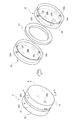
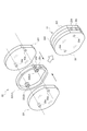
- 3A and 3B are a perspective view and an exploded perspective view schematically showing the configuration of the optical measurement cell of the same embodiment.
- FIG. 3 is a cross-sectional view taken along the line AA and the line BB of the optical measurement cell of the same embodiment.
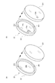
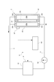
- It is a perspective view which shows the manufacturing method of the transparent plate of the same embodiment. It is a front view of each translucent plate in the same embodiment. It is a fluid path figure showing the circulation course of the temperature control fluid of the embodiment.
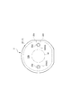
- FIG. 8 is a front view of a transparent plate according to still another embodiment of the present invention.
- FIG. 8 is a front view of a transparent plate according to still another embodiment of the present invention.
- FIG. 8 is a front view of a transparent plate according to still another embodiment of the present invention. It is a typical perspective view showing a measuring stand and a heat insulation jacket in other embodiments of the present invention.
- FIG. 8 is a front view of a transparent plate according to still another embodiment of the present invention.
- FIG. 8 is a front view of a transparent plate according to still another embodiment of the present invention.
- the particle physical property measuring apparatus 100 uses that the light intensity distribution according to the divergence angle of the diffracted / scattered light generated when the particles are irradiated with light is determined by the particle diameter from MIE scattering theory, diffraction theory, or the like.
- the particle size distribution measuring device measures the particle size distribution by detecting the diffracted / scattered light.
- the particle physical property measuring device 100 accommodates a sample X (hereinafter also referred to as a sample fluid X) in which particles to be measured are dispersed in a dispersion medium that is a fluid.
- a sample fluid X hereinafter also referred to as a sample fluid X
- Optical measurement cell 2 a laser device 4 as a light source for irradiating the sample fluid X in the optical measurement cell 2 with measurement light (laser light) through a lens 3, and diffraction / scattering caused by the laser light irradiation.
- a plurality of photodetectors 10 that detect the light intensity of light according to the divergence angle, and a light intensity signal output from each photodetector 10 are received to calculate the particle size distribution of particles contained in the sample fluid X.
- an arithmetic unit Y an arithmetic unit
- reference numeral 7 indicates a cell holder that supports the optical measurement cell
- reference numeral 9 indicates a measurement stand that supports the optical measurement cell 2 via the cell holder 7.
- the cell holder 7 includes a holder main body 71 attached to the side peripheral surface of the optical measurement cell 2 so as to cover the side peripheral surface, and a pedestal member 72 supporting the holder main body 71. Is.
- the optical measurement cell 2 is arranged so as to face each other with a spacer 21 in the shape of an annular band and a spacer 21 sandwiched from both sides with a certain gap.
- the front view is circular and includes a pair of disc-shaped light-transmitting plates 22.
- the sample fluid can be accommodated in a space SS (hereinafter referred to as a sample accommodating space SS) surrounded by the facing surface of each translucent plate 22 and the inner peripheral surface of the spacer 21.
- a space SS hereinafter referred to as a sample accommodating space SS
- the symbol W shown in FIG. 6 indicates the passage region of the measurement light.
- the translucent plate 22 is made of, for example, silicon dioxide (SiO 2 ) as a material that transmits the laser light without being attenuated as much as possible and has corrosion resistance to the sample fluid.
- the spacer 21 is also made of the same material as the translucent plate 22 here.
- a sample fluid is introduced into the sample storage space SS at one edge of the pair of translucent plates 22.
- a pouring / injecting hole 22a for penetrating in the thickness direction is provided.
- the symbol G shown in FIG. 2 is a plug that seals the pouring / injecting hole 22a.
- the temperature control fluid storage chamber 22b is formed inside the light transmitting plate 22, and the temperature control fluid storage chamber 22b will be described later.
- the temperature control fluid is adjusted to a predetermined temperature by the temperature control mechanism 6 so as to flow therethrough.
- the temperature control fluid storage chamber 22b is formed over the central region of the translucent plate 22 excluding its outer edge portion, has a substantially circular shape in front view, and has a constant thickness.
- the temperature control fluid storage chamber 22b is provided with an introduction port 22c for introducing the temperature control fluid and an outlet port 22d for leading out the temperature control fluid, and the temperature control fluid is stored in the temperature control fluid storage chamber 22b. It is configured to circulate through the chamber 22b.
- the introduction port 22c is an opening provided at the lower end of the side surface of the transparent plate 22 when the transparent plate 22 is in an upright position, that is, when the face plate portion is substantially vertical. Then, the temperature control fluid is introduced from the lower end portion of the inner peripheral surface of the temperature control fluid storage chamber 22b via the introduction port 22c and the introduction flow path 22e extending above the introduction port 22c.
- the outlet port 22d is an opening provided at the upper end of the side surface of the translucent plate 22 in the measurement posture. Then, the temperature control fluid in the temperature control fluid storage chamber 22b is led out to the outside from the outlet port 22d via the outlet flow path 22f extending above the upper end of the inner peripheral surface thereof.
- the translucent plate 22 is manufactured by bonding a pair of translucent plate elements 221 which are halved in the thickness direction, as shown in FIG.
- the temperature control fluid is a transparent liquid having a refractive index within a predetermined range (within ⁇ 5%) of the refractive index of the translucent plate 22 in the wavelength range of the laser light.
- silicone oil is used.
- water or hot water may be used, or a gas such as air may be used.
- the circulation path 5 returning to the chamber 22b is provided in the housing of the particle physical property measuring device 100.
- a storage tank 51 and pump means 52 are provided in the middle of the circulation path 5.
- the above-mentioned temperature adjusting mechanism 6 includes a heater 61 provided in the storage tank 51, a temperature sensor 62 attached to a portion of the face plate portion of the translucent plate 22 that avoids the light passage region, and the temperature sensor 62.
- the control means 63 is an electric circuit for controlling the heater 61 so as to bring the measured temperature close to a predetermined target temperature.
- the temperature sensor may be a non-contact type such as a radiation thermometer.
- a temperature control fluid whose temperature is controlled by the temperature control mechanism 6 is circulated to stabilize it at the same temperature as the actual measurement. Then, in that state, a blank measurement is performed. Next, the sample fluid is injected into the optical measurement cell 2, and the temperature control fluid is circulated in the same manner to stabilize the temperature. Then, in that state, the sample fluid is actually measured, and the particle size distribution is calculated in consideration of the blank measurement result.
- the temperature control fluid storage space 22b is formed along substantially the entire surface of the double-sided plate portion in the sample storage space SS, and the temperature control fluid is supplied to the sample fluid in the sample storage space SS. Since the heat is evenly transferred in the direction of the face plate, a spatial temperature gradient can hardly occur in the sample fluid, and the temperature of the temperature control fluid can be quickly (responsively) transferred to the sample fluid.
- the temperature of the sample fluid and the temperature of the temperature control fluid follow very well spatially and temporally, so that the temperature control of the temperature control fluid controls the spatial temperature gradient and temporal variation of the sample.
- the temperature change can be suppressed and the sample can be kept in a stable state, and the reproducibility and accuracy of measurement can be improved.
- the temperature control fluid can be circulated in the temperature control fluid storage space 22b without staying, and the temperature control can be more suitably performed.
- the refractive index of the temperature control fluid and the refractive index of the light transmitting plate 22 are set to be equal to or close to each other, light is less likely to be scattered at the boundary between the temperature control fluid and the light transmitting plate, and the particle size distribution is calculated. It is not necessary to add a correction or the like due to the difference in refractive index of the temperature control fluid to the calculation of, for example, an existing cell that does not use the temperature control fluid and the optical measurement cell 2 of this embodiment are not changed in calculation. Can be used for Of course, these cells may be used after the calculation is corrected.
- the present invention is not limited to the above embodiment.
- the inlet port 22c and the outlet port 22d for introducing the temperature control fluid into the temperature control fluid storage chamber 22b may be provided on opposite sides of the temperature control fluid storage chamber 22b as in the above embodiment. As shown in FIG. 8, they may be arranged on the same side, that is, on one side when the translucent plate 22 is viewed from the face plate direction and the translucent plate is halved when viewed from the front. As a result, the introduction port 22c and the derivation port 22d can be arranged adjacent to each other, and it is possible to arrange the piping for the temperature control fluid connected thereto and reduce the space.
- the optical measurement cell 2 shown in FIG. 8 has a pair of sample fluid pouring / injecting holes 22a on the face plate portion.
- a flow type in which the sample fluid flows through the optical measuring cell 2 during measurement.
- it is a flow type, it can be suitably used as an in-line monitor during the manufacturing process.
- it is more preferable to control the temperature of the sample fluid with a heater or the like on the flow path, for example, near the upstream of the optical measurement cell 2.
- a heater or the like it is more preferable to control the temperature of the sample fluid with a heater or the like on the flow path, for example, near the upstream of the optical measurement cell 2.
- one pouring / injecting hole 22a is sealed with a plug or the like, it can be used as a batch type.
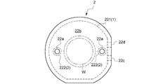
- the transparent plate 22 that constitutes the optical measurement cell 2 includes a pair of transparent plate elements 221, and spacer elements that are sandwiched between the transparent plate elements 221 to form the temperature control fluid storage chamber 22b. And 222.
- the spacer element 222 has a first spacer 222 (1) having an annular shape and a pouring / injecting hole 22a in the light-transmitting plate 22 on which the pouring / injecting hole 22a is formed.
- the optical measuring cell 2 is not shown, but the second spacer element 222 (2) is not used.
- the temperature control fluid accommodation space 22b may be arranged so as to avoid the measurement light passage region W in the translucent plate 22.
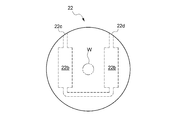
- 10 and 11 show examples in which the temperature control fluid storage chamber 22b is arranged so as to sandwich the measurement light passage region W from both sides, and in FIG. 12, the temperature control fluid storage chamber 22b surrounds the measurement light passage region W.
- An example of arranging is shown. With such a configuration, it is possible to reduce the influence of the temperature control fluid on the measurement light, so that it is possible to reduce the restrictions on the refractive index and the transmittance when selecting the temperature control fluid, and to increase the degree of freedom in selection. it can.
- FIG. 12 is a modification of FIG.
- the temperature control fluid storage chamber 22b may be provided only on one side of the translucent plate 22. In this case, if the thickness of the other translucent plate 22 is reduced, the sample fluid temperature in the sample accommodating space SS can be accurately measured through the other translucent plate 22 by, for example, a radiation thermometer. It will be possible.
- the optical measurement cell 2 is not limited to a circular shape when viewed from the front, and may have various shapes such as a rectangular shape and a square shape.
- the spacer does not have to be a separate body from the transparent plate 22, and may be formed integrally with one transparent plate 22 or both transparent plates 22.
- a groove may be formed in the center of one glass plate in the thickness direction, and this groove may be used as the sample storage space SS.
- a very thin spacer for example, 5 ⁇ m or less
- the optical measurement cell 2 is of a batch type in which the sample fluid is sealed for each measurement.
- a pair of sample fluid inlet / outlet holes are provided so that the sample fluid is A flow type that circulates the measurement cell 2 may be used. If it is a flow type, it can be suitably used as an in-line monitor during the manufacturing process. In the case of a flow type, it is more preferable to control the temperature of the sample fluid with a heater or the like on the flow path, for example, near the upstream of the optical measurement cell 2.
- a holder temperature adjusting mechanism for adjusting the temperature of the holder main body 71 as shown in FIG. 2 to adjust the temperature of the optical measuring cell 2 from the side peripheral surface may be further added, or the cell holder main body 71 may be provided with a heat retaining function. You may add.
- the measuring table 9 of the particle physical property measuring apparatus 100 is configured to be detachable from the measuring apparatus main body, and in the measuring table 9, a heat insulation jacket 91 that covers the optical measurement cell 2 and An attachment structure for detachably attaching the second heater 92 and the fan 93 may be further provided.
- the heat insulation jacket 91 is made of a material having excellent heat insulation properties, and the second heater 92 and the fan 93 respectively heat and control the internal space on the measurement table 9 covered by the heat insulation jacket 91 to circulate air. It is what makes them.
- the result of the blank measurement performed once is stored in the memory, and, for example, the peripheral conditions may be greatly changed or the measurement may be performed.
- the blank measurement result stored in the memory may be reused as long as the interval is not significantly large.
- Automatic opening / closing mechanism that automatically opens / closes the heat insulation jacket may be provided.
- a heating element that transmits all or part of the measurement light may be provided on the surface of the transparent plate 22.
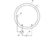
- FIG. 14 An example is shown in FIG. In FIG. 14, a transparent electrode Z1 in the form of a film or a thin plate, which is a heating element, is attached to the surface of the translucent plate 22, and an electric current is passed through the transparent electrode Z1 to generate heat.
- the temperature of the sample can be adjusted to a desired temperature from the face plate direction of the optical measurement cell 2 by controlling the amount of current.
- reference numeral 62 is a temperature sensor
- reference numeral 65 is a current adjusting device as a temperature controller
- reference numeral 66 is a power source.
- a heating wire Z2 which is a heating element, is laid on the surface of the transparent plate 22, and a current is passed through the heating wire Z2 to generate heat.
- the temperature may be adjusted from the face plate direction.
- heating wire not only heating wire but also heat conducting wire such as metal wire may be used. In that case, heat is appropriately conducted from the heat source to the heat conducting wire to generate heat.
- the heating element may be located on the optical path of the measurement light, and scattering, reflection, absorption, etc. may occur there and affect the measurement. Therefore, in the temperature-controlled state, nothing is put in the sample storage space, or only the dispersion medium is put, background measurement is performed, and the effect of each heating element on each photodetector is measured. The influence of the background should be subtracted.
- An optical measurement cell having both the heating element Z and the temperature control fluid storage chamber 22b may be used.
- the measurement light becomes difficult to pass through, and the intensity of the forward scattered light decreases. Therefore, by using a long-wavelength first measurement light (for example, red laser light) having a high light intensity, the transmitted light intensity is increased to increase the upper limit of the measurable concentration on the large particle diameter side, and on the small particle diameter side.
- a possible mode is one in which the second measurement light (for example, blue LED light) having a low light intensity and a short wavelength is used, and the particle diameter and the like are measured by the backscattered light.
- the photodetector for the backscattered light is provided with an optical filter that blocks the first measurement light
- the photodetector for the forward scattered light is an optical filter that blocks the second measurement light if it is affected. If the filter is provided, the sample can be irradiated with the first measurement light and the second measurement light at the same time for measurement.
- the dispersion medium may be not only a fluid but also a gel or jelly.
- the above-mentioned particle size distribution measuring device is of so-called static light scattering type (SLS), but other particle size distribution measuring devices such as so-called dynamic light scattering type (DLS) and other physical properties of particles are It may be applied to an apparatus for measuring particle physical properties.
- SLS static light scattering type
- DLS dynamic light scattering type
- the present invention is not limited to the above-described embodiment, and various modifications can be made without departing from the spirit of the invention, such as combining some modified embodiments.
Landscapes
- Chemical & Material Sciences (AREA)
- Biochemistry (AREA)
- Physics & Mathematics (AREA)
- Health & Medical Sciences (AREA)
- Life Sciences & Earth Sciences (AREA)
- Analytical Chemistry (AREA)
- General Health & Medical Sciences (AREA)
- General Physics & Mathematics (AREA)
- Immunology (AREA)
- Pathology (AREA)
- Dispersion Chemistry (AREA)
- Optical Measuring Cells (AREA)
- Investigating Or Analysing Materials By Optical Means (AREA)
Abstract
隙間SSを空けて互いに対向するように配置された一対の透光板22を有し、該透光板22を介して、前記隙間SSに入れられた試料流体を光学的に測定できるようにしたものであって、前記透光板22の内部に、試料流体の温度を調整するための温調流体が収容される温調流体収容室22dが形成されている光学測定用セルである。
Description
本発明は、粒子径分布などの粒子物性の測定に用いられる光学測定用セル及びこれを用いた粒子物性測定装置に関するものである。
従来、粒子径分布測定装置のような粒子物性測定装置においては、測定対象となる粒子を含んだ試料を透明な光学測定用セルに入れて測定するところ、この試料の温度を、測定時において所望の温度に保ちたいというニーズがある。
これに対し、例えば特許文献1では、光学測定用セルを収容する温調用ボックスを設けて、被測定時に光学測定用セルの温度を所望の温度に調整しておき、測定時には、温調用ボックスの前面及び後面に設けられたシャッタを開いて、光学測定用セルを露出させ、試料流体を測定できるような構成が開示されている。
しかしながら、前述のような構成であると、シャッタの開成によって、その部分の温度が下がり、その内部の試料流体の温度に勾配が生じて温度勾配が生じ得る。そして、この温度勾配は、測定時間(シャッタの開成時間)や周囲温度によって変動するため、測定の再現性や精度に問題が生じ得る。
本発明は、上述した不具合を解決すべくなされたものであって、試料の温度勾配や温度変化を生じにくくし、測定の再現性や精度を向上させることが可能な光学測定用セルを提供することをその主たる所期課題としたものである。
すなわち、本発明に係る光学測定用セルは、隙間を空けて互いに対向するように配置された一対の透光板を有し、該透光板を介して、前記隙間に入れられた試料を光学的に測定できるようにしたものであって、前記透光板の内部に、試料の温度を調整するための温調流体が収容される温調流体収容室が形成されていることを特徴とする。
このようなものであれば、隙間内の試料に、温調流体から面板方向に可及的均一に熱を伝えることができるため、該試料に空間的な温度勾配が生じることを抑制できるうえ、温調流体の温度が素早く(応答性よく)試料に伝えられることとなる。
したがって、温調流体の温度制御によって、例えば、試料の空間的な温度勾配や時間的な温度変化を抑制して試料を安定な状態に保つことができ、測定の再現性や精度を向上させることが可能となる。
したがって、温調流体の温度制御によって、例えば、試料の空間的な温度勾配や時間的な温度変化を抑制して試料を安定な状態に保つことができ、測定の再現性や精度を向上させることが可能となる。
温調流体による測定への影響を軽減するには、前記温調流体の屈折率が、測定に用いられる光(以下、測定光ともいう。)の波長域において、透光板の屈折率と等しいか又は近しいことが望ましい。
前記温調流体収容室が、透光板の外縁部を除く中心領域に亘って形成されていれば、光学測定用セルに入れられている試料に対し、透光板の面板方向略全面から伝熱できるので、試料の温調をより早く、かつ均一に行うことができる。
温調流体の測定光に対する影響を軽減するには、前記温調流体収容室が、測定光の通過領域を避けて形成されているものが好ましい。
具体的な実施態様としては、前記温調流体収容室が、測定光の通過領域を両側から挟み込むように、または測定光通過領域の周囲を取り囲むように形成されているものを挙げることができる。
温調流体による伝熱作用を効率よく営ませるには、前記温調流体収容室に、前記温調流体を導入するための導入ポートと前記温調流体を導出するための導出ポートとが設けられており、該温調流体が前記温調流体収容室を流通するように構成されているものが好適である。
温調流体の導入時における気泡発生を抑制するには、前記導入ポートが、前記温調流体収容室の下方に設けられているものが望ましい。
温調流体の配管の取り回し等を容易化するには、前記導入ポート及び導出ポートが、前記透光板を面板方向から視て、該透光板を半割した場合の一方側にともに配置されているものがよい。
温調流体収容室内を、温調流体が滞留なく流通するようにするには、前記導入ポート及び導出ポートが、前記透光板を面板方向から視て、該透光板を半割した場合の互いに逆側に配置されているものが好ましい。
本発明によれば、試料に対し、温調流体から面板方向に均一に熱が伝えられるため、該試料に空間的な温度勾配がほとんど生じ得ないうえ、温調流体の温度が素早く(応答性よく)試料に伝えられることとなる。したがって、温調流体の温度制御によって、例えば、試料の空間的な温度勾配や時間的な温度変化を抑制して試料を安定な状態に保つことができ、測定の再現性や精度を向上させることが可能となる。
100・・・粒子物性測定装置
2・・・光学測定用セル
22・・・透光板22
22b・・・温調流体収容室
22c・・・導入ポート
22d・・・導出ポート
SS・・・試料流体収容空間(隙間)
2・・・光学測定用セル
22・・・透光板22
22b・・・温調流体収容室
22c・・・導入ポート
22d・・・導出ポート
SS・・・試料流体収容空間(隙間)
以下に本発明に係る光学測定用セルを用いた粒子物性測定装置の一実施形態について図面を参照して説明する。
本実施形態に係る粒子物性測定装置100は、粒子に光を照射した際に生じる回折/散乱光の拡がり角に応じる光強度分布が、MIE散乱理論や回折理論等から粒子径によって定まることを利用し、前記回折/散乱光を検出することによって粒子径分布を測定する粒子径分布測定装置である。
具体的にこの粒子物性測定装置100は、図1及び図2に示すように、流体である分散媒に測定対象となる粒子を分散させた試料X(以下、試料流体Xともいう。)を収容する光学測定用セル2と、該光学測定用セル2内の試料流体Xにレンズ3を介して測定光(レーザ光)を照射する光源たるレーザ装置4と、レーザ光の照射により生じる回折/散乱光の光強度を拡がり角に応じて検出する複数の光検出器10と、各光検出器10から出力された光強度信号を受信して試料流体Xに含まれる粒子の粒子径分布を算出する演算装置Yとを備えている。
なお、同図中、符号7は、光学測定用セルを支持するセルホルダを示し、符号9は、このセルホルダ7を介して光学測定用セル2を支持する測定台を示している。前記セルホルダ7は、図2に示すように、光学測定用セル2の側周面に、これを覆うように取り付けられるホルダ本体71と、このホルダ本体71を支持する台座部材72とを備えたものである。
次に、前記光学測定用セル2の詳細を説明する。
この光学測定用セル2は、図3~図6に示すように、円環帯状をなすスペーサ21と、このスペーサ21を両側から挟み込むことによって一定の隙間を空けて互いに対向するように配置された円盤状をなす一対の透光板22とを備えた、正面視、円形状をなすものである。そして、各透光板22の対向面とスペーサ21の内周面とによって囲まれた空間SS(以下、試料収容空間SSという。)に試料流体を収容できるようにしてある。なお、図6に示す符号Wは、測定光の通過領域を示している。
透光板22は、レーザ光を可及的に減衰させることなく透過させるとともに、試料流体に対して耐食性を有する、例えば二酸化ケイ素(SiO2)を素材とするものである。スペーサ21も、ここでは透光板22と同一の素材で形成されている。
一対の透光板22のうちの一方の縁部には、図3、図4(b)、図5(b)、図6(b)に示すように、試料流体を前記試料収容空間SSに注入出するための、厚み方向に貫通する注出入孔22aが設けられている。なお、図2に示す符号Gは、前記注出入孔22aを封止する栓である。
しかして、この実施形態では、図3~図6に示すように、前記透光板22の内部に温調流体収容室22bが形成してあり、この温調流体収容室22b内を、後述する温度調整機構6によって所定の温度に調整された温調流体が流通するように構成してある。
前記温調流体収容室22bは、透光板22においてその外縁部を除く中心領域に亘って形成されたものであり、正面視概略円形状をなし、その厚みは一定である。
この温調流体収容室22bには、前記温調流体を導入するための導入ポート22cと前記温調流体を導出するための導出ポート22dとが設けられていて、温調流体が温調流体収容室22bを流通するように構成してある。
前記導入ポート22cは、透光板22を立てた姿勢、すなわちその面板部を略鉛直にした測定時姿勢において、該透光板22の側周面下端部に設けられた開口である。そして、温調流体は、この導入ポート22c及びその上方に延伸する導入流路22eを介して、温調流体収容室22bの内側周面下端部から導入される。
前記導出ポート22dは、前記測定時姿勢において該透光板22の側周面上端部に設けられた開口である。そして、温調流体収容室22b内の温調流体は、その内側周面上端部の上方に延伸する導出流路22fを介して、該導出ポート22dから外部に導出される。
なお、この透光板22は、図5に示すように、厚み方向に半割した一対の透光板要素221を貼り合わせることによって製造する。
前記温調流体は、前記レーザ光の波長域において、その屈折率が透光板22の屈折率の所定範囲内(±5%以内)にある透明液体であり、ここでは、シリコーンオイルを使っている。その他、水や湯などでもよいし、空気などの気体でも構わない。この実施形態においては、例えば図7に示すように、前記導入ポート22cを介して前記温調流体収容室22bに導入した温調流体を、前記導出ポート22dから導出して、再度温調流体収容室22bに戻す循環経路5が、粒子物性測定装置100の筐体内に設けてある。この循環経路5の途中には、貯留槽51とポンプ手段52とが設けてある。前述した温度調整機構6は、前記貯留槽51に設けられたヒータ61と、透光板22の面板部における光通過領域を避けた部位に貼り付けられた温度センサ62と、この温度センサ62による測定温度を所定の目標温度に近づけるべく前記ヒータ61を制御する電気回路である制御手段63とを具備したものである。なお、温度センサは、放射温度計など、非接触のものでも構わない。
測定にあたっては、まず分散媒のみを光学測定用セル2に注入したブランク状態で、温度調整機構6によって温調した温調流体を循環させ、実測定と同じ温度に安定させる。そして、その状態で、ブランク測定をする。次に、試料流体を光学測定用セル2に注入して、同様に温調流体を循環させ、温度を安定させる。そして、その状態で、試料流体を実測定し、ブランク測定結果を加味して粒子径分布を算出する。
しかしてこのようなものであれば、試料収容空間SSにおける両面板部のほぼ全面に沿って、温調流体収容空間22bが形成されており、試料収容空間SS内の試料流体に温調流体から面板方向に均一に熱が伝えられるため、該試料流体に空間的な温度勾配がほとんど生じ得ないうえ、温調流体の温度が素早く(応答性よく)試料流体に伝えられることとなる。
このように、試料流体の温度と温調流体の温度とが空間的にも時間的にも極めて良好に追随するので、温調流体の温度制御によって、試料の空間的な温度勾配や時間的な温度変化を抑制して試料を安定な状態に保つことができ、測定の再現性や精度を向上させることが可能となる。
この効果は、高濃度試料の場合に特に顕著となる。高濃度試料の場合は、光の透過性を向上させるために試料収容空間SSの厚みを薄くする必要があるところ、その面板方向から伝熱させているので、側周面から伝熱させた場合に比べ、試料流体に均一にしかも非常に素早く熱が伝わり、温度制御性、温度再現性、温度安定性等が格段に向上する。
また、例えばタンパク質などのように、温度によって不可逆的に性質が変化する試料に対しては、空間的な温度勾配によって部分的な変成が生じやすいところ、そのような現象も確実に防止できる。さらに、均一に素早く試料流体温度を制御できることから、温調流体の温度を経時的に徐々に変化させて、たんぱく質変性の時間変化を精度よく測定することも可能になる。
他方、導入ポート22cが温調流体収容空間22bの下方に設けられていて、温調流体が温調流体収容空間22bの下から導入されるため、気泡が生じにくく、その気泡による測定誤差を可及的に低減させることができる。
さらに、導入ポート22cの逆側に導出ポート22dが設けられているので、温調流体を滞留させることなく、温調流体収容空間22bに流通させることができ、温度調整をより好適に行える。
また、温調流体の屈折率と透光板22の屈折率とを等しいか近しくしているので、温調流体と透光板の境目で光の散乱が生じにくいうえ、粒径分布算出時の演算に、温調流体の屈折率の違いによる補正等を加えずに済み、例えば、温調流体を用いない既存のセルと、この実施形態の光学測定用セル2とを、演算の変更なしに使うことができる。なお当然ことながら、これらのセルを演算を補正して使用してもよい。
なお、本発明は前記実施形態に限られるものではない。
例えば、温調流体収容室22bへの温調流体の導入ポート22c及び導出ポート22dは、前記実施形態のように、温調流体収容室22bを挟んで互いに逆側に設けられたものでもよいし、図8に示すように、同じ側、すなわち透光板22を面板方向から視て、該透光板を正面から視て半割した場合の一方側にともに配置してもよい。このことによって、導入ポート22c及び導出ポート22dとが隣り合うようにでき、そこに接続される温調流体の配管の取り回しやスペース削減を図ることができる。
また、この図8に示す光学測定用セル2は、試料流体の注出入孔22aを面板部上に一対設けている。このことによって、注出入孔22aのうち、一方を注入用、他方を注出用とすることにより、測定中に試料流体が光学測定用セル2を流通するフロー式のものに対応できる。フロー式のものであれば、製造プロセス中のインラインモニタとしても好適に用いることができる。またフロー式のものであれば、試料流体を、その流通経路上の、例えば光学測定用セル2の上流近傍において、ヒータなどで温調しておけば、より好ましい。もちろん、一方の注出入孔22aを栓などによって封止すれば、バッチ式のものにも使用できる。
ここでこの光学測定用セル2について補足しておく。該光学測定用セル2を構成している透光板22は、図9に示すように、一対の透光板要素221と、その間に挟まれて前記温調流体収容室22bを形成するスペーサ要素222とを具備したものである。前記スペーサ―要素222は、注出入孔22aが形成される一方の透光板22においては、図9に示すように、環状をなす第1スペーサ222(1)と、注出入孔22aを形成する管状の第2スペーサ要素222(2)との2種類がある。他方を光学測定用セル2は、図示しないが、第2スペーサ要素222(2)は用いない。
温調流体収容空間22bを、透光板22における測定光通過領域Wを避けて配置してもよい。図10、図11に、測定光通過領域Wを両側から挟み込むように温調流体収容室22bを配置した例、図12に、測定光通過領域Wの周囲を取り囲むように温調流体収容室22bを配置した例を示す。このようなものであれば、測定光に対する温調流体の影響を小さくすることができるので、温調流体選択の際の屈折率や透過率の制限を小さくでき、その選択自由度を上げることができる。なお、図12は、図8の変形である。
透光板22の一方にのみ温調流体収容室22bを設けてもよい。その場合、他方の透光板22は、厚みを小さくすれば、この他方の透光板22を介して、例えば放射温度計により、試料収容空間SS内の試料流体温度を精度よく測定することが可能になる。
光学測定用セル2は、正面視、円形状に限らず、矩形状や正方形状など、種々の形状で構わない。また、スペーサは、透光板22と別体である必要はなく、一方の透光板22又は両方の透光板22に一体的に形成されていてもよい。例えば、1枚のガラス板の厚み方向中央に溝を形成し、この溝を試料収容空間SSとしてもよい。その他に、例えば、特願2018-117570号に記載されているように、一方の透光板22の周縁部に、蒸着によって一体に、非常に厚みの薄い(例えば5μm以下)のスペーサを形成してもよい。このようなものであれば、厚みが極めて小さくしかも寸法精度の高い試料収容空間を形成でき、非常に濃度の高い流体試料を精度よく測定することができる。
前記実施形態においては、光学測定用セル2は、測定毎に試料流体が封入されるバッチ式のものであったが、試料流体の注出入孔を一対設けておき、測定中に試料流体が光学測定用セル2を流通するフロー式のものにしてもよい。フロー式のものであれば、製造プロセス中のインラインモニタとしても好適に用いることができる。またフロー式のものであれば、試料流体を、その流通経路上の、例えば光学測定用セル2の上流近傍において、ヒータなどで温調しておけば、より好ましい。
図2に示すようなホルダ本体71を温調して、光学測定用セル2を側周面からも温調するホルダ温調機構をさらに付加しても構わないし、あるいはセルホルダ本体71に保温機能を付加してもよい。
また、粒子物性測定装置100の測定台9を、図13に示すように、測定装置本体から取り外し可能に構成しておき、この測定台9において、光学測定用セル2を覆う保温ジャケット91と、第2ヒータ92及びファン93を着脱可能に取り付ける取付構造をさらに設けておいてもよい。保温ジャケット91は断熱性に優れた素材で構成されたものであり、第2ヒータ92及びファン93は、保温ジャケット91によって覆われた測定台9上の内部空間をそれぞれ加熱温調し、空気循環させるものである。
この構成の場合、この測定台9を測定装置本体から取り外した状態で、保温ジャケット91を取り付け、測定前に予め光学測定用セル2を温調しておくことができる。測定時(ブランク測定時も含む)には、測定台9から保温ジャケット91、第2ヒータ92及びファン93を取り外し、測定装置本体に取り付ける。
なお、このような場合、試料流体の測定毎にブランク測定を行っていると手間がかかるので、一度行ったブランク測定結果をメモリに保存しておき、例えば、周辺条件が大きく変動したり、測定の間隔が大幅に空いたりしない限りにおいて、メモリに保存したブランク測定結果を使い回しするようにしてもよい。
前記保温ジャケットを自動で開閉する自動開閉機構を設けてもよい。
透光板22の表面に、測定光を全部または一部透過させる発熱体を設けてもよい。
その一例を図14に示す。この図14では、発熱体である膜状又は薄板状をなす透明電極Z1を透光板22の表面に貼り付け、この透明電極Z1に電流を流すことによって発熱させる。そしてその電流量を制御することにより、試料を光学測定用セル2の面板方向から所望の温度に温調できるようにしてある。なお、同図中符号62は温度センサ、符号65は温調器たる電流調整装置、符号66は電源である。
また、図15に示すように、発熱体である電熱線Z2を透光板22の表面に敷設し、この電熱線Z2に電流を流すことによって発熱させ、同様に、試料を光学測定用セル2の面板方向から温調できるようにしてもよい。
さらに、電熱線のみならず、金属線などの熱伝導線でもよい。その場合は、熱伝導線に適宜熱源から熱を伝導させ、発熱させる。
上述した構成の場合、発熱体が測定光の光路上に位置し、そこで散乱や反射、吸収等が生じて測定に影響を及ぼす場合がある。そこで、温調した状態で試料収容空間には何も入れず、あるいは分散媒のみを入れて、バックグランド測定を行い、発熱体による各光検出器への影響を測定し、実際の測定時には、そのバックグランドによる影響を差し引くようにすればよい。
以上のような発熱体Zと前記温調流体収容室22bとを双方有するような光学測定用セルにしてもよい。
試料における粒子濃度が極めて高い場合、測定光が透過しにくくなり、前方散乱光の強度が小さくなる。そこで、光強度の高い長波長の第1測定光(例えば赤色のレーザ光)を用い、透過光強度を増大させて、大粒子径側の測定可能濃度の上限を高める一方、小粒子径側については、光強度が低く短波長の第2測定光(例えば青色のLED光)を用い、その後方散乱光によって粒子径等を測定する態様が考えられる。この場合、後方散乱光の光検出器には、第1測定光を遮断する光学フィルタを設け、前方散乱光の光検出器には、影響が出るのであれば、第2測定光を遮断する光学フィルタを設ければ、第1測定光と第2測定光を同時に試料に照射して測定することができる。
分散媒は、流体のみならず、ゲルやゼリーなどでも構わない。上述の粒子径分布測定装置は、いわゆる静的光散乱式(SLS)のものであるが、いわゆる動的光散乱式(DLS)など、その他の粒子径分布測定装置や、粒子の他の物性を測定する粒子物性測定装置に適用しても構わない。
その他、本発明は前記実施形態に限られず、種々の変形実施形態の一部を組み合わせるなど、その趣旨を逸脱しない範囲で種々の変形が可能であるのは言うまでもない。
その他、本発明は前記実施形態に限られず、種々の変形実施形態の一部を組み合わせるなど、その趣旨を逸脱しない範囲で種々の変形が可能であるのは言うまでもない。
再現性良く安定した測定が可能な光学測定用セルを提供できる。
Claims (11)
- 隙間を空けて互いに対向するように配置された一対の透光板を有し、該透光板を介して、前記隙間に入れられた試料を光学的に測定できるようにした粒子物性測定用のものであって、
前記透光板の内部に、試料の温度を調整するための温調流体が収容される温調流体収容室が形成されていることを特徴とする光学測定用セル。 - 前記温調流体の屈折率が、測定に用いられる光(以下、測定光ともいう。)の波長域において、透光板の屈折率と等しいか又は近しいことを特徴とする請求項1記載の光学測定用セル。
- 前記温調流体収容室が、透光板の外縁部を除く中心領域に亘って形成されていることを特徴とする請求項1記載の光学測定用セル。
- 前記温調流体収容室が、測定光の通過領域を避けて形成されていることを特徴とする請求項1記載の光学測定用セル。
- 前記温調流体収容室が、測定光の通過領域を両側から挟み込むように、または測定光の通過領域の周囲を取り囲むように形成されていることを特徴とする請求項4記載の光学測定用セル。
- 前記温調流体収容室に、前記温調流体を導入するための導入ポートと前記温調流体を導出するための導出ポートとが設けられており、該温調流体が前記温調流体収容室を流通するように構成されていることを特徴とする請求項1記載の光学測定用セル。
- 前記導入ポートが、前記温調流体収容室の下方に設けられていることを特徴とする請求項6記載の光学測定用セル。
- 前記導入ポート及び導出ポートが、前記透光板を面板方向から視て、該透光板を半割した場合の一方側にともに配置されていることを特徴とする請求項6記載の光学測定用セル。
- 前記導入ポート及び導出ポートが、前記透光板を面板方向から視て、該透光板を半割した場合の互いに逆側に配置されていることを特徴とする請求項6記載の光学測定用セル。
- 請求項1記載の光学測定用セルを備えていることを特徴とする粒子物性測定装置。
- 前記温調流体の温度を調整する温調手段と、前記温調手段により温調された温調流体を前記光学測定用セルに送出するポンプ手段とをさらに備えていることを特徴とする請求項10記載の粒子物性測定装置。
Priority Applications (1)
| Application Number | Priority Date | Filing Date | Title |
|---|---|---|---|
| JP2020556679A JP7221298B2 (ja) | 2018-11-06 | 2019-09-27 | 粒子物性測定に用いられる光学測定用セル及びこれを用いた粒子物性測定装置 |
Applications Claiming Priority (2)
| Application Number | Priority Date | Filing Date | Title |
|---|---|---|---|
| JP2018208646 | 2018-11-06 | ||
| JP2018-208646 | 2018-11-06 |
Publications (1)
| Publication Number | Publication Date |
|---|---|
| WO2020095569A1 true WO2020095569A1 (ja) | 2020-05-14 |
Family
ID=70612346
Family Applications (1)
| Application Number | Title | Priority Date | Filing Date |
|---|---|---|---|
| PCT/JP2019/038350 Ceased WO2020095569A1 (ja) | 2018-11-06 | 2019-09-27 | 粒子物性測定に用いられる光学測定用セル及びこれを用いた粒子物性測定装置 |
Country Status (2)
| Country | Link |
|---|---|
| JP (1) | JP7221298B2 (ja) |
| WO (1) | WO2020095569A1 (ja) |
Families Citing this family (1)
| Publication number | Priority date | Publication date | Assignee | Title |
|---|---|---|---|---|
| JP2025011897A (ja) * | 2023-07-12 | 2025-01-24 | 株式会社 堀場アドバンスドテクノ | 測定計、測定装置、測定システム、及び測定方法 |
Citations (8)
| Publication number | Priority date | Publication date | Assignee | Title |
|---|---|---|---|---|
| JPS59112252A (ja) * | 1982-12-20 | 1984-06-28 | Toshiba Corp | 恒温フロ−セルの製造方法 |
| JPS6088258U (ja) * | 1983-11-22 | 1985-06-17 | 株式会社島津製作所 | 分析用恒温セルホルダ |
| JPS6375854U (ja) * | 1986-11-06 | 1988-05-20 | ||
| JPH04369464A (ja) * | 1991-06-17 | 1992-12-22 | Rion Co Ltd | 光散乱式粒子検出装置 |
| JP2000356584A (ja) * | 1999-06-11 | 2000-12-26 | Ricoh Co Ltd | 被検物温度制御装置 |
| US6670170B1 (en) * | 2000-05-15 | 2003-12-30 | The United States Of America As Represented By The Secretary Of The Army | Temperature-regulated cell perifusion chamber |
| JP2013160633A (ja) * | 2012-02-06 | 2013-08-19 | Shimadzu Corp | 粒度分布測定装置 |
| CN106680225A (zh) * | 2016-12-31 | 2017-05-17 | 郑州贯奥仪器仪表有限公司 | 一种用于多参数水质检测仪的样品反应检测装置 |
-
2019
- 2019-09-27 WO PCT/JP2019/038350 patent/WO2020095569A1/ja not_active Ceased
- 2019-09-27 JP JP2020556679A patent/JP7221298B2/ja active Active
Patent Citations (8)
| Publication number | Priority date | Publication date | Assignee | Title |
|---|---|---|---|---|
| JPS59112252A (ja) * | 1982-12-20 | 1984-06-28 | Toshiba Corp | 恒温フロ−セルの製造方法 |
| JPS6088258U (ja) * | 1983-11-22 | 1985-06-17 | 株式会社島津製作所 | 分析用恒温セルホルダ |
| JPS6375854U (ja) * | 1986-11-06 | 1988-05-20 | ||
| JPH04369464A (ja) * | 1991-06-17 | 1992-12-22 | Rion Co Ltd | 光散乱式粒子検出装置 |
| JP2000356584A (ja) * | 1999-06-11 | 2000-12-26 | Ricoh Co Ltd | 被検物温度制御装置 |
| US6670170B1 (en) * | 2000-05-15 | 2003-12-30 | The United States Of America As Represented By The Secretary Of The Army | Temperature-regulated cell perifusion chamber |
| JP2013160633A (ja) * | 2012-02-06 | 2013-08-19 | Shimadzu Corp | 粒度分布測定装置 |
| CN106680225A (zh) * | 2016-12-31 | 2017-05-17 | 郑州贯奥仪器仪表有限公司 | 一种用于多参数水质检测仪的样品反应检测装置 |
Also Published As
| Publication number | Publication date |
|---|---|
| JPWO2020095569A1 (ja) | 2021-09-30 |
| JP7221298B2 (ja) | 2023-02-13 |
Similar Documents
| Publication | Publication Date | Title |
|---|---|---|
| CN104458636B (zh) | 一种具有温度气压自动补偿的co2气体浓度监测装置及方法 | |
| US4440497A (en) | Combination absorbance fluorescence aspirating thermal cuvette | |
| JP2014064507A (ja) | 培養容器、培養観察装置及び培養観察方法 | |
| CN114279562B (zh) | 一种变温条件下黑体腔吸收系数的定标方法 | |
| JP7360100B2 (ja) | 濃度測定装置 | |
| CN110440911B (zh) | 一种低温辐射计用测试集成装置及测试方法 | |
| CN104749115A (zh) | 一种测量薄膜材料热光系数的装置及方法 | |
| WO2020095569A1 (ja) | 粒子物性測定に用いられる光学測定用セル及びこれを用いた粒子物性測定装置 | |
| KR102007507B1 (ko) | 온도 제어 수단을 구비한 ir 분광 분석 셀 | |
| EP2914952B1 (fr) | Dispositif d'acquisition d'une image d'un échantillon, comportant un organe de régulation du chauffage d'un support de réception de l'échantillon, et système d'imagerie associé | |
| CN114136842B (zh) | 一种光学法测量高温流体黏度和表面张力的装置 | |
| CN109813680A (zh) | 一种用于测量的实体及其应用 | |
| CN108593483B (zh) | 一种基于激光加热的高升温率热重分析系统及方法 | |
| Kikuchi et al. | Depth measurement of molecular permeation using inclined confocal microscopy | |
| CN202119714U (zh) | 一种实验室用表面反照率测量系统 | |
| CN207013864U (zh) | 带测温振镜同轴加工系统 | |
| CN121409403B (zh) | 一种水下辐射传感器设备浸没因子快速测量装置及方法 | |
| JP5712946B2 (ja) | 粒度分布測定装置 | |
| RU2811326C1 (ru) | Способ измерения теплофизических свойств материалов и установка для его осуществления с использованием датчиков теплового потока | |
| RU231094U1 (ru) | Фотометр | |
| JP2585947B2 (ja) | 屈折率測定方法及びその装置 | |
| JP7835873B2 (ja) | 検体分析装置 | |
| RU2807433C1 (ru) | Способ измерения теплофизических свойств материалов и установка для его осуществления с использованием термовизоров | |
| US2922301A (en) | Apparatus for determining the evaporation end point of volatile liquids | |
| CN217304887U (zh) | 一种光谱水质检测样品测量室 |
Legal Events
| Date | Code | Title | Description |
|---|---|---|---|
| 121 | Ep: the epo has been informed by wipo that ep was designated in this application |
Ref document number: 19882149 Country of ref document: EP Kind code of ref document: A1 |
|
| ENP | Entry into the national phase |
Ref document number: 2020556679 Country of ref document: JP Kind code of ref document: A |
|
| NENP | Non-entry into the national phase |
Ref country code: DE |
|
| 122 | Ep: pct application non-entry in european phase |
Ref document number: 19882149 Country of ref document: EP Kind code of ref document: A1 |