WO2020095490A1 - スイッチ装置、通信制御方法および通信制御プログラム - Google Patents
スイッチ装置、通信制御方法および通信制御プログラム Download PDFInfo
- Publication number
- WO2020095490A1 WO2020095490A1 PCT/JP2019/030217 JP2019030217W WO2020095490A1 WO 2020095490 A1 WO2020095490 A1 WO 2020095490A1 JP 2019030217 W JP2019030217 W JP 2019030217W WO 2020095490 A1 WO2020095490 A1 WO 2020095490A1
- Authority
- WO
- WIPO (PCT)
- Prior art keywords
- vehicle
- unit
- switch
- switch device
- communication data
- Prior art date
- Legal status (The legal status is an assumption and is not a legal conclusion. Google has not performed a legal analysis and makes no representation as to the accuracy of the status listed.)
- Ceased
Links
Images







Classifications
-
- H—ELECTRICITY
- H04—ELECTRIC COMMUNICATION TECHNIQUE
- H04L—TRANSMISSION OF DIGITAL INFORMATION, e.g. TELEGRAPHIC COMMUNICATION
- H04L12/00—Data switching networks
- H04L12/28—Data switching networks characterised by path configuration, e.g. LAN [Local Area Networks] or WAN [Wide Area Networks]
- H04L12/40—Bus networks
- H04L12/4013—Management of data rate on the bus
- H04L12/40136—Nodes adapting their rate to the physical link properties
-
- H—ELECTRICITY
- H04—ELECTRIC COMMUNICATION TECHNIQUE
- H04L—TRANSMISSION OF DIGITAL INFORMATION, e.g. TELEGRAPHIC COMMUNICATION
- H04L12/00—Data switching networks
- H04L12/28—Data switching networks characterised by path configuration, e.g. LAN [Local Area Networks] or WAN [Wide Area Networks]
- H04L12/46—Interconnection of networks
- H04L12/4641—Virtual LANs, VLANs, e.g. virtual private networks [VPN]
-
- H—ELECTRICITY
- H04—ELECTRIC COMMUNICATION TECHNIQUE
- H04L—TRANSMISSION OF DIGITAL INFORMATION, e.g. TELEGRAPHIC COMMUNICATION
- H04L12/00—Data switching networks
- H04L12/28—Data switching networks characterised by path configuration, e.g. LAN [Local Area Networks] or WAN [Wide Area Networks]
- H04L12/40—Bus networks
- H04L12/40052—High-speed IEEE 1394 serial bus
- H04L12/40065—Bandwidth and channel allocation
-
- H—ELECTRICITY
- H04—ELECTRIC COMMUNICATION TECHNIQUE
- H04L—TRANSMISSION OF DIGITAL INFORMATION, e.g. TELEGRAPHIC COMMUNICATION
- H04L12/00—Data switching networks
- H04L12/28—Data switching networks characterised by path configuration, e.g. LAN [Local Area Networks] or WAN [Wide Area Networks]
- H04L12/40—Bus networks
- H04L12/40169—Flexible bus arrangements
- H04L12/40176—Flexible bus arrangements involving redundancy
-
- H—ELECTRICITY
- H04—ELECTRIC COMMUNICATION TECHNIQUE
- H04L—TRANSMISSION OF DIGITAL INFORMATION, e.g. TELEGRAPHIC COMMUNICATION
- H04L12/00—Data switching networks
- H04L12/28—Data switching networks characterised by path configuration, e.g. LAN [Local Area Networks] or WAN [Wide Area Networks]
- H04L12/40—Bus networks
- H04L2012/40267—Bus for use in transportation systems
- H04L2012/40273—Bus for use in transportation systems the transportation system being a vehicle
Definitions
- the present invention relates to a switch device, a communication control method, and a communication control program.
- This application claims the priority on the basis of Japanese application Japanese Patent Application No. 2018-208356 for which it applied on November 5, 2018, and takes in those the indications of all here.
- Patent Document 1 Japanese Patent Laid-Open No. 2013-168865 discloses the following in-vehicle network system. That is, the in-vehicle network system includes an in-vehicle control device including a memory that stores definition data that defines a part of the communication protocol used on the in-vehicle network that depends on the implementation on the in-vehicle network, and the in-vehicle control device. And a communication protocol issuing device for issuing the definition data.
- the communication protocol issuing device When the communication protocol issuing device receives a registration request for requesting the in-vehicle control device to participate in the in-vehicle network from a registration device that causes the in-vehicle control device to participate in the in-vehicle network, the communication protocol issuing device authenticates the registration device.
- the definition data that complies with the above implementation is created in the in-vehicle network and returned to the registration device.
- the registration device receives the definition data transmitted by the communication protocol issuing device, and requests the vehicle-mounted control device to store the received definition data in the memory.
- the in-vehicle control device receives the definition data from the registration device, stores the definition data in the memory, and communicates using the in-vehicle network in accordance with the communication protocol according to the portion defined by the definition data. ..
- a switch device is a switch device mounted on a vehicle, and holds a switch unit that relays communication data between a plurality of functional units mounted on the vehicle and the communication data that should be relayed. And a control unit that determines the state of the storage unit and adjusts the throughput of the communication data transmitted from the functional unit for each application based on the determination result.
- the communication control method is a switch control apparatus mounted on a vehicle, the switch control apparatus including a storage unit that holds communication data to be relayed. Relaying communication data between the functional units, and determining the state of the storage unit and adjusting the throughput of the communication data transmitted from the functional units for each application based on the determination result. ..
- the communication control program according to the present disclosure is a switch control apparatus installed in a vehicle, the switch control apparatus including a storage unit that holds communication data to be relayed.
- the state of the switch unit that relays communication data between the plurality of functional units and the storage unit is determined, and the throughput of the communication data transmitted from the functional unit is adjusted for each application based on the determination result. It is a program for functioning as a control unit.
- One aspect of the present disclosure can be realized not only as a switch device including such a characteristic processing unit but also as an in-vehicle communication system including the switch device. Further, one embodiment of the present disclosure can be realized as a semiconductor integrated circuit which realizes part or all of a switch device.
- FIG. 1 is a diagram showing a configuration of an in-vehicle communication system according to the embodiment of the present invention.
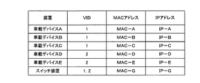
- FIG. 2 is a diagram showing an example of the VID, MAC address, and IP address of each device in the vehicle-mounted communication system according to the embodiment of the present invention.
- FIG. 3 is a diagram showing an example of an Ethernet frame transmitted in the vehicle-mounted communication system according to the embodiment of the present invention.
- FIG. 4 is a diagram showing a configuration of the switch device in the vehicle-mounted communication system according to the embodiment of the present invention.
- FIG. 5 is a diagram showing a configuration of the L2 switch processing unit in the switch device according to the exemplary embodiment of the present invention.
- FIG. 6 is a diagram showing a configuration of the L3 relay processing unit in the switch device according to the exemplary embodiment of the present invention.
- FIG. 7 is a diagram showing data stored in the storage unit of the L3 relay processing unit in the switch device according to the exemplary embodiment of the present invention.
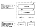
- FIG. 8 is a diagram showing an example of a transmission path of an Ethernet frame subjected to L3 relay processing in the vehicle-mounted communication system according to the embodiment of the present invention.
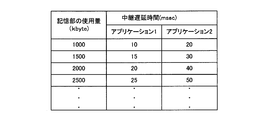
- FIG. 9 is a diagram showing an example of a delay time table held by the control unit in the switch device according to the exemplary embodiment of the present invention.
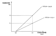
- FIG. 10 is a diagram showing an example of the relationship between the usage amount of the storage unit and the delay time of the ACK frame in the switch device according to the exemplary embodiment of the present invention.
- FIG. 11 is a diagram showing an example of a communication data throughput adjustment sequence in the vehicle-mounted communication system according to the embodiment of the present invention.
- FIG. 12 is a diagram showing an example of a window size table held by the control unit in the switch device according to the embodiment of the present invention.
- FIG. 13 is a diagram showing an example of the relationship between the usage amount of the storage unit and the window size reduction amount in the switch device according to the embodiment of the present invention.
- FIG. 14 is a diagram showing an example of a communication data throughput adjustment sequence in the vehicle-mounted communication system according to the embodiment of the present invention.
- FIG. 15 is a diagram showing an example of a usage amount estimation table held by the control unit in the switch device according to the embodiment of the present invention.
- FIG. 16 is a flowchart that defines an operation procedure when the switch device adjusts the throughput of communication data transmitted from the in-vehicle device in the in-vehicle communication system according to the embodiment of the present invention.
- FIG. 17 is a flowchart that defines an operation procedure when the switch device adjusts the throughput of communication data transmitted from the in-vehicle device in the in-vehicle communication system according to the embodiment of the present invention.
- an in-vehicle network system has been developed to improve security in the in-vehicle network.
- the vehicle-mounted network described in Patent Document 1 is provided with a communication gateway that relays communication data transmitted and received between vehicle-mounted ECUs (Electronic Control Units).
- vehicle-mounted ECUs Electronic Control Units
- the communication gateway may receive a large amount of communication data from the vehicle-mounted ECU and become congested.
- the present disclosure has been made to solve the above problems, and an object of the present disclosure is to provide a switch device, a communication control method, and a communication control program that can realize a more stable communication environment in an in-vehicle network. Is.
- a switch device is a switch device mounted on a vehicle, and should be relayed with a switch unit that relays communication data between a plurality of functional units mounted on the vehicle.
- a storage unit that holds the communication data, and a control unit that determines the state of the storage unit and adjusts the throughput of the communication data transmitted from the functional unit for each application based on the determination result.
- the throughput of communication data transmitted from the functional unit can be adjusted for each application according to the state of the storage unit. For example, when the switch device is in a congestion state, it is possible to selectively limit the transmission of communication data according to the priority of the application. As a result, the congestion state of the switch device can be alleviated without significantly reducing the communication data throughput related to the high-priority application, and the retention and transmission delay of the communication data in the switch device can be adjusted in a well-balanced manner. it can. Therefore, a more stable communication environment can be realized in the vehicle-mounted network.
- the functional unit transmits the communication data when receiving an ACK from another functional unit, and the control unit adjusts the throughput by delaying the relay of the ACK by the switch unit. To do.
- control unit delays the relay of the ACK, so that the transmission timing of the next communication data by the functional unit can be delayed.
- the throughput can be adjusted for each application while using the existing processing.
- the functional unit transmits the communication data in an amount according to the transmission size information received from another functional unit per unit time, and the control unit receives the communication data received by the switch unit.
- the throughput is adjusted by changing the content of the transmission size information and relaying it to the switch unit.
- control unit changes the content of the transmission size information and relays it to the switch unit, so that the functional unit can adjust the amount of communication data to be transmitted next.
- the throughput can be adjusted for each application while using the existing processing.
- the switch device further includes a plurality of communication ports, the switch unit transmits and receives the communication data via the communication port, and the control unit controls the communication data at the communication port.
- the state is determined based on the transmission rate of
- the state of the storage unit can be predicted in advance based on the transmission rate at the communication port, and the state of the storage unit can be determined based on the prediction result. Accordingly, for example, the throughput of communication data transmitted from the functional unit can be adjusted for each application before the storage unit actually runs short of capacity.
- control unit compares the ACK received this time and the ACK received last time from the same functional unit, and determines whether to delay the relay of the ACK received this time according to the comparison result. To decide.
- the functional unit when the functional unit cannot normally receive the communication data transmitted from the other functional unit, the functional unit sends a plurality of ACKs to the other functional unit to request the other functional unit to retransmit the communication data. May be sent consecutively. In this case, with the above configuration, it is possible to prevent the retransmission of communication data from being delayed.
- a communication control method is a communication control method in a switch device mounted on a vehicle, the switch device including a storage unit for holding communication data to be relayed.
- a step of performing is a communication control method in a switch device mounted on a vehicle, the switch device including a storage unit for holding communication data to be relayed.
- the throughput of communication data transmitted from the functional unit can be adjusted for each application according to the state of the storage unit. For example, when the switch device is in a congestion state, it is possible to selectively limit the transmission of communication data according to the priority of the application. As a result, the congestion state of the switch device can be alleviated without significantly reducing the communication data throughput related to the high-priority application, and the retention and transmission delay of the communication data in the switch device can be adjusted in a well-balanced manner. it can. Therefore, a more stable communication environment can be realized in the vehicle-mounted network.
- a communication control program is a communication control program in a switch device that is installed in a vehicle and includes a storage unit that holds communication data to be relayed. A state of the storage unit and a switch unit that relays communication data between a plurality of functional units mounted on the vehicle, and based on the determination result, a throughput of the communication data transmitted from the functional unit. It is a program that functions as a control unit that adjusts for each application.
- the throughput of communication data transmitted from the functional unit can be adjusted for each application according to the state of the storage unit. For example, when the switch device is in a congestion state, it is possible to selectively limit the transmission of communication data according to the priority of the application. As a result, the congestion state of the switch device can be alleviated without significantly reducing the communication data throughput related to the high-priority application, and the retention and transmission delay of the communication data in the switch device can be adjusted in a well-balanced manner. it can. Therefore, a more stable communication environment can be realized in the vehicle-mounted network.
- FIG. 1 is a diagram showing a configuration of an in-vehicle communication system according to the embodiment of the present invention.
- an in-vehicle communication system 301 includes a switch device 101 and a plurality of in-vehicle devices 111.
- the in-vehicle communication system 301 is mounted on the vehicle 1.
- each of the vehicle-mounted devices 111A, 111B, 111C, 111D, and 111E is also referred to as a vehicle-mounted device 111.
- the vehicle-mounted device 111 is an example of a functional unit.
- the vehicle-mounted communication system 301 is not limited to the configuration including the five vehicle-mounted devices 111, and may have a configuration including two, three, four, or six or more vehicle-mounted devices 111.
- the in-vehicle device 111 is, for example, an automatic driving ECU (Electronic Control Unit), an image sensor, a radar device, a navigation device, a TCU (Telematics Communication Unit), a central gateway (CGW), a human machine interface, etc. It is possible to communicate.
- the in-vehicle device 111 is not limited to these specific examples, and may be another device mounted in the vehicle 1 and capable of communicating with the switch device 101.
- the switch device 101 and the in-vehicle device 111 are connected to each other by, for example, the Ethernet (registered trademark) cable 10.
- the connection relationship between the switch device 101 and each in-vehicle device 111 in the in-vehicle network of the vehicle 1 is fixed, for example.
- the switch device 101 and the in-vehicle device 111 communicate with each other using an Ethernet cable. Communication data is exchanged between the switch device 101 and the in-vehicle device 111 by using, for example, an Ethernet frame according to IEEE802.3.
- the in-vehicle device 111 has a function of one or a plurality of applications.
- the in-vehicle device 111 transmits and receives information regarding its own application via the switch device 101.
- the in-vehicle device 111 which is an image sensor, periodically captures an image of the surroundings of the vehicle 1 and creates image information indicating the capture result.
- the in-vehicle device 111 which is a radar device, periodically creates detection information indicating a detection result of an object such as a pedestrian around the vehicle 1 by using millimeter waves. To do.
- the in-vehicle device 111 which is an autonomous driving ECU, assists the automatic driving based on, for example, image information received from an image sensor and detection information received from a radar device.
- FIG. 2 is a diagram showing an example of the VID, MAC address, and IP address of each device in the vehicle-mounted communication system according to the embodiment of the present invention.
- vehicle-mounted devices 111A, 111B, 111C and vehicle-mounted devices 111D, 111E belong to different VLANs (Virtual Local Area Networks).
- the ID of the VLAN to which the in-vehicle devices 111A, 111B, 111C belong (hereinafter also referred to as VID) is 1.
- the VID to which the in-vehicle devices 111D and 111E belong is 2.
- the switch device 101 and the in-vehicle device 111 have a unique MAC (Media Access Control) address and IP (Internet Protocol) address.
- MAC Media Access Control
- IP Internet Protocol
- the switch device 101 performs a relay process of relaying communication data between a plurality of vehicle-mounted devices 111 in the vehicle-mounted network.
- IP packets are transmitted and received using IP packets according to the IP protocol, for example.
- IP packet is stored and transmitted in an Ethernet frame which is an example of communication data.
- the switch device 101 performs a relay process for relaying an Ethernet frame transmitted between the in-vehicle devices 111.
- the switch device 101 operates according to a communication protocol having multiple layers. More specifically, the switch device 101 can function as an L2 (layer 2) switch, and relays an Ethernet frame between the vehicle-mounted devices 111 that belong to the same VLAN. The switch device 101 can also function as an L3 (layer 3) relay device, and relays Ethernet frames between the vehicle-mounted devices 111 that belong to different VLANs.
- L2 layer 2
- L3 layer 3
- FIG. 3 is a diagram showing an example of an Ethernet frame transmitted in the vehicle-mounted communication system according to the embodiment of the present invention.
- an Ethernet frame has an Ethernet header field, an IP header field, a TCP header field, a data field, and a CRC (Cyclic Redundancy Check) field.
- the destination MAC address, the source MAC address, and the type are stored in the Ethernet header field.
- An IP header, a source IP address, and a destination IP address are stored in the IP header field.
- Arbitrary data and padding as needed are stored in the data field.
- a CRC value is stored in the CRC field.
- the TCP header field stores a destination port number, a source port number, a sequence number, an acknowledgment number, a header length and a session flag, a window size, a checksum, and an urgent pointer.
- the header length and session flag fields include a header length, an NS (Nonce Sum) flag, a CWR (Congestion Window Reduced) flag, an ESE flag, an URG (Urgent) flag, an ACK (Acknowledgement) flag, and PSH.
- a (Push) flag, an RST (Reset) flag, a SYN (Synchronize) flag, and a FIN (Fin) flag are stored.
- the vehicle-mounted device 111B transmits an IP packet including image information or detection information to the vehicle-mounted device 111C
- the IP packet includes IP-B and IP-C as the source IP address and the destination IP address, respectively. included.
- the in-vehicle device 111B belongs to the same VLAN as itself and the in-vehicle device 111C, 1, MAC-C and MAC-B are written in the Ethernet frame as VID, destination MAC address and source MAC address, respectively.
- the in-vehicle device 111B transmits the Ethernet frame storing the IP packet to the switch device 101.
- the switching device 101 When the switch device 101 receives the Ethernet frame from the in-vehicle device 111B, the switching device 101 performs the layer 2 switch process on the received Ethernet frame to transmit the Ethernet frame to the in-vehicle device 111C.
- the vehicle-mounted device 111B transmits an IP packet including image information or detection information to the vehicle-mounted device 111D
- the IP packet includes IP-B and IP-D as a source IP address and a destination IP address. Are included respectively.
- the MAC address of the switch device 101 which is the default gateway, that is, MAC-G and MAC-B are set as VID and destination MAC address. And the source MAC address in the Ethernet frame.
- the in-vehicle device 111B transmits the Ethernet frame storing the IP packet to the switch device 101.
- the switch device 101 Upon receiving the Ethernet frame from the vehicle-mounted device 111B, the switch device 101 transmits the Ethernet frame to the vehicle-mounted device 111D by performing layer 3 relay processing on the received Ethernet frame.
- the in-vehicle device 111C or 111D receives the Ethernet frame via the switch device 101, the in-vehicle device 111C or 111D returns an Ethernet frame (hereinafter also referred to as an ACK frame) in which the ACK flag is set to 1 to the in-vehicle device 111B.
- an Ethernet frame hereinafter also referred to as an ACK frame
- the vehicle-mounted device 111B Upon receiving the ACK frame from the vehicle-mounted device 111C or 111D, the vehicle-mounted device 111B transmits the next Ethernet frame to the vehicle-mounted device 111C or 111D.
- the in-vehicle device 111C or 111D notifies the in-vehicle device 111B of transmission size information regarding the amount of data that the in-vehicle device 111 can receive next.
- the in-vehicle device 111B transmits an Ethernet frame having a data amount corresponding to the notified transmission size information per unit time.
- the vehicle-mounted device 111C or 111D transmits an ACK frame in which transmission size information, for example, the window size is stored.
- the in-vehicle device 111B receives the ACK frame and transmits an Ethernet frame having an upper limit of the data amount according to the window size stored in the ACK frame to the in-vehicle device 111C or 111D.
- FIG. 4 is a diagram showing a configuration of the switch device in the vehicle-mounted communication system according to the embodiment of the present invention.
- the switch device 101 includes an L2 switch processing unit 60, an L3 relay processing unit 70, and communication ports 54A, 54B, 54C, 54D, 54E that are communication ports 54.
- the switch device 101 is not limited to the configuration in which the five communication ports 54 are provided, and may have the configuration in which two, three, four, or six or more communication ports 54 are provided.
- the communication port 54 is a terminal to which the Ethernet cable 10 can be connected, for example.
- the communication port 54 may be a terminal of the integrated circuit.
- Each of the plurality of communication ports 54 is connected to any one of the plurality of vehicle-mounted devices 111 via the Ethernet cable 10. Further, each of the plurality of communication ports 54 is associated with, for example, a VLAN.
- the L2 switch processing unit 60 operates, for example, as an L2 switch and relays an Ethernet frame between the vehicle-mounted devices 111 belonging to the same VLAN.
- the L3 relay processing unit 70 operates, for example, as an L3 switch and relays an Ethernet frame between the vehicle-mounted devices 111 belonging to different VLANs.
- FIG. 5 is a diagram showing the configuration of the L2 switch processing unit in the switch device according to the embodiment of the present invention.
- the L2 switch processing unit 60 includes an L2 switch unit 61 and a storage unit 62.
- the L2 switch unit 61 performs a layer 2 switch process on the Ethernet frame received via the communication port 54. Upon receiving the Ethernet frame to be relayed, the L2 switch unit 61 stores the received Ethernet frame in the storage unit 62.
- FIG. 6 is a diagram showing the configuration of the L3 relay processing unit in the switch device according to the embodiment of the present invention.
- L3 relay processing unit 70 includes L3 relay unit 71, storage unit 72, control unit 73, and timer 74.
- the L3 relay unit 71 performs layer 3 switch processing on the Ethernet frame received from the L2 switch unit 61.
- the L3 relay unit 71 stores the received Ethernet frame in the storage unit 72.
- the storage unit 72 is provided with a queue for each application, for example.
- FIG. 7 is a diagram showing data stored in the storage unit of the L3 relay processing unit in the switch device according to the exemplary embodiment of the present invention.
- the storage unit 72 is provided with a queue 72A corresponding to a certain application and a queue 72B corresponding to another application.
- the L3 relay unit 71 identifies the corresponding application by referring to the source port number included in the Ethernet frame, allocates the Ethernet frame to the corresponding queue for each application, and stores the Ethernet frame in the storage unit 72.
- the storage unit 72 may have a configuration in which three or more queues are provided.
- the control unit 73 determines the state of the storage unit 72, and adjusts the throughput of communication data transmitted from the in-vehicle device 111 for each application based on the determination result. Details of how the control unit 73 adjusts the throughput of communication data for each application will be described later.
- the L2 switch unit 61 can perform relay processing according to Layer 2, for example, without passing through the L3 relay processing unit 70.
- the L2 switch unit 61 has, for example, a plurality of terminals connected to the L3 relay processing unit 70 and the communication ports 54A, 54B, 54C, 54D, 54E, respectively.
- a unique logical port number is assigned to each terminal.
- the logical port numbers of the terminals connected to the L3 relay processing unit 70 and the communication ports 54A, 54B, 54C, 54D, 54E are # 0, # 1, # 2, # 3, # 4 and # 5, respectively. Is.
- the L2 switch unit 61 holds, for example, an ARL table (Address Resolution Logic).
- the contents of the ARL table are predetermined by the user, for example, based on the connection relationship fixed in the vehicle-mounted network as described above.
- the ARL table indicates, for example, the correspondence relationship between the destination MAC address and the output destination.
- the output destination is a logical port number.
- the correspondence relationship between the MAC address of the vehicle-mounted device 111 and the logical port number of the terminal to which the vehicle-mounted device 111 is connected, the MAC address of its own switch device 101, and the L3 relay processing unit is included.
- the L2 switch unit 61 stores the received Ethernet frame in the storage unit 62 and acquires the destination MAC address included in the Ethernet frame.
- the L2 switch unit 61 acquires the logical port number corresponding to the acquired destination MAC address from the ARL table. Specifically, the L2 switch unit 61 acquires the acquired destination MAC for an Ethernet frame transmitted in the same VLAN such as an Ethernet frame transmitted from the vehicle-mounted device 111B to the vehicle-mounted device 111C. Any one of # 1 to # 5 is acquired as the logical port number corresponding to the address.
- the L2 switch unit 61 acquires a corresponding Ethernet frame from the storage unit 62, and transmits the acquired Ethernet frame from the terminal of the acquired logical port number to the in-vehicle device 111 via the communication port 54.
- the L2 switch unit 61 corresponds to the acquired destination MAC address for an Ethernet frame transmitted between different VLANs such as an Ethernet frame transmitted from the vehicle-mounted device 111A to the vehicle-mounted device 111E.
- # 0 is acquired as the logical port number.
- the L2 switch unit 61 acquires the corresponding Ethernet frame from the storage unit 62 and outputs the acquired Ethernet frame to the L3 relay processing unit 70.
- the L3 relay unit 71 performs relay processing via the L2 switch processing unit 60. Specifically, the L3 relay unit 71 performs the relay process according to the layer 3 which is higher than the layer 2.
- the L3 relay unit 71 performs layer 3 relay processing (hereinafter, also referred to as L3 relay processing) on the Ethernet frame received from the L2 switch processing unit 60.
- L3 relay processing layer 3 relay processing
- the L3 relay unit 71 receives the Ethernet frame from the L2 switch processing unit 60, and rewrites the destination MAC address and the source MAC address of the received Ethernet frame.
- the L3 relay unit 71 holds, for example, table information TIA indicating a correspondence relationship between an IP address and a MAC address used for layer 3 relay processing.
- the L3 relay unit 71 has a routing table indicating a correspondence relationship between a destination network to be relayed by itself, for example, a VLAN and a VID, and an ARP indicating a correspondence relationship between an IP address and a MAC address for each VID.
- Holds table information TIA including the (Address Resolution Protocol) table.
- the content of the table information TIA is predetermined by the user, for example, based on the connection relationship fixed in the vehicle-mounted network as described above.
- the L3 relay unit 71 Upon receiving the Ethernet frame from the L2 switch processing unit 60, the L3 relay unit 71 stores the received Ethernet frame in the storage unit 72. Further, the L3 relay unit 71 acquires the destination IP address from the IP packet included in the received Ethernet frame and, for example, performs subnet mask calculation on the acquired destination IP address to specify the VLAN.
- the L3 relay unit 71 refers to the routing table and acquires the VID corresponding to the specified VLAN.
- the L3 relay unit 71 refers to the ARP table corresponding to the acquired VID, and acquires the MAC address corresponding to the destination IP address from the ARP table.
- the L3 relay unit 71 acquires the Ethernet frame from the storage unit 72, acquires the VID, the destination MAC address, and the source MAC address in the acquired Ethernet frame, the acquired VID and MAC address, and the MAC of its own switch device 101. Each address is rewritten and output to the L2 switch processing unit 60.
- FIG. 8 is a diagram showing an example of a transmission path of an Ethernet frame subjected to L3 relay processing in the vehicle-mounted communication system according to the embodiment of the present invention.
- the vehicle-mounted device 111A transmits, for example, an Ethernet frame whose destination is the vehicle-mounted device 111E.
- the in-vehicle device 111A transmits, to the switch device 101, an Ethernet frame including 1, MAC-A, MAC-G, and IP-E as the VID, the source MAC address, the destination MAC address, and the destination IP address, respectively. To do.
- the L3 relay processing unit 70 in the switch device 101 When receiving the Ethernet frame from the vehicle-mounted device 111A via the communication port 54A and the L2 switch processing unit 60, the L3 relay processing unit 70 in the switch device 101 performs the L3 relay processing on the received Ethernet frame based on the table information TIA. To do.
- the L3 relay unit 71 receives the Ethernet frame from the L2 switch processing unit 60 and stores the received Ethernet frame in the storage unit 72. Then, the L3 relay unit 71 acquires the Ethernet frame from the storage unit 72, and rewrites the VID, the source MAC address, and the destination MAC address included in the acquired Ethernet frame to 2, MAC-G and MAC-E, respectively. .. The L3 relay unit 71 outputs the rewritten Ethernet frame to the L2 switch processing unit 60.
- the L2 switch processing unit 60 Upon receiving the Ethernet frame from the L3 relay processing unit 70, the L2 switch processing unit 60 acquires the logical port number # 5 corresponding to the destination MAC address included in the received Ethernet frame based on the ARL table.
- the L2 switch processing unit 60 transmits an Ethernet frame from the acquired terminal having the logical port number # 5 via the communication port 54E. As a result, the Ethernet frame is transmitted to the in-vehicle device 111E via the communication port 54E.
- the priority is set according to the in-vehicle device 111 that is the source of the Ethernet frame, and the pause frame is transmitted to the in-vehicle device 111 having a low priority.
- the frequency of Ethernet frames transmitted from the vehicle-mounted device 111 having a low priority can be reduced, and the Ethernet frame from the vehicle-mounted device 111 having a high priority can be preferentially relayed, so that the storage unit 72 overflows. It is possible to reduce the possibility that
- the control unit 73 determines the state of the storage unit 72. More specifically, the control unit 73 monitors the storage unit 72 regularly or irregularly and checks the state of the storage unit 72 by referring to the amount of data or the number of Ethernet frames held in the storage unit 72. judge. The control unit 73 monitors the L3 relay unit 71, and when the L3 relay unit 71 receives the Ethernet frame from the L2 switch processing unit 60, the control unit 73 refers to the amount of data held in the storage unit 72 or the number of Ethernet frames. By doing so, the state of the storage unit 72 may be determined.
- the control unit 73 adjusts the throughput of communication data transmitted from the vehicle-mounted device 111 for each application based on the result of the determination.
- the throughput of communication data is proportional to the window size divided by RTT (Round Trip Time).
- Each device in the in-vehicle communication system 301 includes a computer including a memory, and an arithmetic processing unit such as a CPU in the computer reads out a program including some or all of the steps of the following flowchart and sequence from the memory. Run.
- the programs of these plural devices can be installed from the outside.
- the programs of these plural devices are distributed in a state of being stored in a recording medium.
- the switch device 101 increases the RTT between the in-vehicle devices 111 by delaying the relay of the ACK from the in-vehicle device 111 of the transmission destination, thereby adjusting the throughput of communication data for each application.
- the switch device 101 delays the relay of the ACK frame received from the transmission destination vehicle-mounted device 111. More specifically, the control unit 73 delays the transmission timing of the ACK frame by the L3 relay unit 71.
- the priority of the application 1 is higher than that of the application 2, and the Ethernet frame F1 corresponding to the application 1 is relayed and transmitted to the in-vehicle device 111E with a higher priority than the Ethernet frame F2 corresponding to the application 2. It is necessary.
- the control unit 73 determines the delay time of the transmission timing of the ACK frame by the L3 relay unit 71 (hereinafter, also referred to as relay delay time) according to the state of the storage unit 72, and adjusts the timing of relaying the ACK frame. ..
- FIG. 9 is a diagram showing an example of a delay time table held by the control unit in the switch device according to the embodiment of the present invention.
- control unit 73 associates the amount of data held in the storage unit 72 (hereinafter, also referred to as the amount of use of the storage unit 72) C and the relay delay time T for each application.
- a delay time table indicating the relationship is held, and the relay delay time is determined by referring to the delay time table.
- the relay delay time T1 of the application 1 is 10 milliseconds and the relay delay time T2 of the application 2 is 20 milliseconds when the usage amount C1 of the storage unit 72 is 1000 kbytes or more and less than 1500 kbytes. is there. Further, for example, the relay delay time T1 of the application 1 is 15 milliseconds and the relay delay time T2 of the application 2 is 30 milliseconds when the usage amount C1 of the storage unit 72 is 1500 kbytes or more and less than 2000 kbytes.
- the control unit 73 determines that it is necessary to delay the transmission timing of the ACK frame by the L3 relay unit 71, and the usage amount C1 of the storage unit 72. Is less than 1000 kbytes, it is determined that it is not necessary to delay the transmission timing of the ACK frame by the L3 relay unit 71.
- FIG. 10 is a diagram showing an example of the relationship between the usage amount of the storage unit and the delay time of the ACK frame in the switch device according to the embodiment of the present invention.
- the vertical axis represents the relay delay time (second)
- the horizontal axis represents the usage amount (byte) of the storage unit.
- the delay time table held by the control unit 73 shows that the relay delay time T corresponds to the usage amount C of the storage unit 72 when the usage amount C of the storage unit 72 is equal to or greater than a predetermined value C0. It is set so that the relay delay time T increases proportionally to the increase in the usage amount C of the storage unit 72 as the priority of the application decreases.
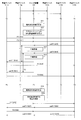
- FIG. 11 is a diagram showing an example of a communication data throughput adjustment sequence in the vehicle-mounted communication system according to the embodiment of the present invention.
- the control unit 73 determines the state of the storage unit 72 at a predetermined timing (step S11).
- control unit 73 determines that it is necessary to delay the transmission timing of the ACK frame by the L3 relay unit 71 as a result of determining the state of the storage unit 72, it sets the relay delay time T for each application. Specifically, the control unit 73 sets the relay delay time T by referring to the delay time table (step S12).
- the in-vehicle device 111A transmits the Ethernet frame F1 corresponding to the application 1 to the in-vehicle device 111E via the switch device 101 (step S13).
- the in-vehicle device 111A transmits the Ethernet frame F2 corresponding to the application 2 to the in-vehicle device 111E via the switch device 101 (step S14).
- the in-vehicle device 111E receives the Ethernet frame F1, it transmits the ACK frame ackF1 for the Ethernet frame F1 to the switch device 101 (step S15).
- the in-vehicle device 111E receives the Ethernet frame F2, it transmits the ACK frame ackF2 for the Ethernet frame F2 to the switch device 101 (step S16).
- the switch device 101 when the switch device 101 receives the ACK frame ackF1, it suspends the transfer of the ACK frame ackF1 for the relay delay time T1 (step S17) and transmits it to the in-vehicle device 111A (step S18).
- the in-vehicle device 111A receives the ACK frame ackF1
- the in-vehicle device 111A transmits the Ethernet frame F1 to be transmitted next to the in-vehicle device 111E via the switch device 101 (step S19).
- the switch device 101 when the switch device 101 receives the ACK frame ackF2, it suspends the transfer of the ACK frame ackF2 for the relay delay time T2 (step S20) and transmits it to the in-vehicle device 111A (step S21).
- the in-vehicle device 111A receives the ACK frame ackF2
- the in-vehicle device 111A transmits the Ethernet frame F2 to be transmitted next to the in-vehicle device 111E via the switch device 101 (step S22).
- control unit 73 determines the state of the storage unit 72 at a predetermined timing after a predetermined time has elapsed from the timing at which the state of the storage unit 72 was previously determined (step S23).
- step S24 if the control unit 73 determines that it is not necessary to delay the transmission timing of the ACK frame by the L3 relay unit 71 as a result of determining the state of the storage unit 72, the setting of the relay delay time T is canceled (step S24). ).
- the in-vehicle device 111A transmits the Ethernet frame F1 corresponding to the application 1 to the in-vehicle device 111E via the switch device 101 (step S25).
- the in-vehicle device 111E upon receiving the Ethernet frame F1, transmits an ACK frame ackF1 for the Ethernet frame F1 to the switch device 101 (step S26).
- the switch device 101 transmits the ACK frame ackF1 to the in-vehicle device 111A without suspending the relay (step S27).
- the in-vehicle device 111A transmits the Ethernet frame F1 corresponding to the application 2 to the in-vehicle device 111E via the switch device 101 (step S28).
- the in-vehicle device 111E receives the Ethernet frame F2, it transmits the ACK frame ackF2 for the Ethernet frame F2 to the switch device 101 (step S29).
- the switch device 101 transmits the ACK frame ackF2 to the in-vehicle device 111A without holding the relay (step S30).
- the L3 relay unit 71 in the switch device 101 receives the ACK frame ackF1 via the L2 switch processing unit 60 in step S17
- the L3 relay unit 71 stores the received ACK frame ackF1 in the storage unit 72.
- the control unit 73 sets the set relay delay time T1 in the timer 74.
- the control unit 73 receives a notification from the timer 74 that the relay delay time T1 has elapsed, and notifies the L3 relay unit 71 of the passage of the relay delay time T1. ..
- the L3 relay unit 71 acquires the ACK frame ackF1 from the storage unit 72, rewrites the VID and the like included in the acquired ACK frame ackF1, and outputs the rewritten VID and the like to the L2 switch processing unit 60.
- step S20 when the L3 relay unit 71 in the switch device 101 receives the ACK frame ackF2 via the L2 switch processing unit 60, the L3 relay unit 71 saves the received ACK frame ackF2 in the storage unit 72.
- the control unit 73 sets the set relay delay time T2 in the timer 74.
- the control unit 73 receives the notification from the timer 74 that the relay delay time T2 has elapsed, and notifies the L3 relay unit 71 of the passage of the relay delay time T2. ..
- the L3 relay unit 71 acquires the ACK frame ackF2 from the storage unit 72, rewrites the VID and the like included in the acquired ACK frame ackF2, and outputs the rewritten VID and the like to the L2 switch processing unit 60.
- the switch device 101 adjusts the timing of transmitting the ACK frame to the destination in-vehicle device 111 according to the usage amount of the storage unit 72.
- the switch device 101 adjusts the data amount per unit time of the communication data to be transmitted next time by the in-vehicle device 111 of the transmission source by changing the content of the transmission size information received from the in-vehicle device 111 of the transmission destination. Adjust the communication data throughput for each application.
- the switch device 101 changes the window size in the ACK frame received from the transmission destination vehicle-mounted device 111. More specifically, the control unit 73 causes the L3 relay unit 71 to change the window size in the ACK frame.
- the control unit 73 determines the reduction amount of the window size according to the state of the storage unit 72, and adjusts the data amount of the Ethernet frame to be transmitted next time.
- FIG. 12 is a diagram showing an example of a window size table held by the control unit in the switch device according to the embodiment of the present invention.
- control unit 73 holds a window size table indicating a correspondence relationship between the usage amount C of the storage unit 72 and the window size reduction amount W for each application.
- the window size reduction amount W is determined, and the upper limit of the data amount of the Ethernet frame to be transmitted next time is adjusted.
- the window size reduction amount W1 of the application 1 is 1000 bytes
- the window size reduction amount W2 of the application 2 is 2000 bytes. It is a byte.
- the window size reduction amount W1 of the application 1 is 1500 bytes and the window size reduction amount W2 of the application 2 is 3000 bytes. ..
- FIG. 13 is a diagram showing an example of a relationship between the usage amount of the storage unit and the reduction amount of the window size in the switch device according to the embodiment of the present invention.
- the vertical axis represents the window size reduction amount (byte)
- the horizontal axis represents the storage unit usage amount (byte).
- control unit 73 determines that the window size needs to be reduced when the usage amount C1 of the storage unit 72 is 1000 kbytes or more, and when the usage amount C1 of the storage unit 72 is less than 1000 kbytes. , Determine that the window size needs to be reduced.
- the window size table held by the control unit 73 shows that when the usage amount C of the storage unit 72 is equal to or larger than a predetermined value C0, the reduction amount W of the window size becomes the usage amount C of the storage unit 72. It is set to be proportional and the lower the priority of the application, the larger the increase amount of the window size reduction amount W with respect to the increase of the usage amount C of the storage unit 72.
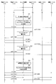
- FIG. 14 is a diagram showing an example of a communication data throughput adjustment sequence in the vehicle-mounted communication system according to the embodiment of the present invention.
- the control unit 73 determines the state of the storage unit 72 at a predetermined timing (step S31).
- control unit 73 determines that the window size needs to be reduced as a result of determining the state of the storage unit 72, it sets the window size reduction amount W for each application. Specifically, the control unit 73 determines the reduction amount W by referring to the window size table (step S32).
- the in-vehicle device 111A transmits the Ethernet frame F1 corresponding to the application 1 to the in-vehicle device 111E via the switch device 101 (step S33).
- the in-vehicle device 111E receives the Ethernet frame F1, it transmits the ACK frame ackF1 for the Ethernet frame F1 to the switch device 101 (step S34).
- the switch device 101 when receiving the ACK frame ackF1, the switch device 101 rewrites the window size included in the TCP header field of the ACK frame ackF1 (step S35), and transmits the rewritten ACK frame ackF1 to the in-vehicle device 111A (step S36). ).
- the switch device 101 transmits the Ethernet frame F1 to be transmitted next with the upper limit of the data amount specified by the window size included in the TCP header field of the ACK frame ackF1. Is transmitted to the in-vehicle device 111E via (step S37).
- the in-vehicle device 111A transmits the Ethernet frame F2 corresponding to the application 2 to the in-vehicle device 111E via the switch device 101 (step S38).
- the in-vehicle device 111E receives the Ethernet frame F2, it transmits the ACK frame ackF2 for the Ethernet frame F2 to the switch device 101 (step S39).
- the switch device 101 when receiving the ACK frame ackF2, the switch device 101 rewrites the window size included in the TCP header field of the ACK frame ackF2 (step S40), and transmits the rewritten ACK frame ackF2 to the in-vehicle device 111A (step S41). ).
- the switch device 101 transmits the Ethernet frame F2 to be transmitted next with the upper limit of the data amount specified by the window size included in the TCP header field of the ACK frame ackF1. Is transmitted to the in-vehicle device 111E via (step S42).
- control unit 73 determines the state of the storage unit 72 at a predetermined timing after a predetermined time has elapsed from the timing at which the state of the storage unit 72 was previously determined (step S43).
- control unit 73 determines that the window size does not need to be reduced as a result of determining the state of the storage unit 72, it cancels the setting of the window size reduction amount W (step S44).
- the in-vehicle device 111A transmits the Ethernet frame F1 corresponding to the application 1 to the in-vehicle device 111E via the switch device 101 (step S45).
- the in-vehicle device 111E receives the Ethernet frame F1, it sends an ACK frame ackF1 for the Ethernet frame F1 to the switch device 101 (step S46).
- the switch device 101 when the switch device 101 receives the ACK frame ackF1, it transmits the ACK frame ackF1 to the in-vehicle device 111A without rewriting the window size included in the ACK frame ackF1 (step S47).
- the in-vehicle device 111A transmits the Ethernet frame F1 corresponding to the application 2 to the in-vehicle device 111E via the switch device 101 (step S48).
- the in-vehicle device 111E receives the Ethernet frame F2, it transmits an ACK frame ackF2 for the Ethernet frame F2 to the switch device 101 (step S49).
- the switch apparatus 101 receives the ACK frame ackF2, it transmits the ACK frame ackF2 to the in-vehicle device 111A without rewriting the window size included in the ACK frame ackF2 (step S50).
- the L3 relay unit 71 in the switch device 101 receives the ACK frame ackF1 via the L2 switch processing unit 60 in step S35, the L3 relay unit 71 saves the received ACK frame ackF1 in the storage unit 72.
- the control unit 73 notifies the L3 relay unit 71 of the reduction amount W1 of the set window size.
- the L3 relay unit 71 acquires the ACK frame ackF1 from the storage unit 72, rewrites the window size included in the ACK frame ackF1 according to the reduction amount W1, and rewrites the VID and the like included in the ACK frame ackF1 to the L2 switch processing unit 60. Output.
- step S40 when the L3 relay unit 71 in the switch device 101 receives the ACK frame ackF2 via the L2 switch processing unit 60, the L3 relay unit 71 saves the received ACK frame ackF2 in the storage unit 72.
- the control unit 73 notifies the L3 relay unit 71 of the set window size reduction amount W2.
- the L3 relay unit 71 acquires the ACK frame ackF2 from the storage unit 72, rewrites the window size included in the ACK frame ackF2 according to the reduction amount W2, and rewrites the VID and the like included in the ACK frame ackF2 to the L2 switch processing unit 60. Output.
- the switch device 101 adjusts the data amount of the Ethernet frame to be transmitted next by the vehicle-mounted device 111A according to the usage amount of the storage unit 72.
- control unit 73 may determine the state of the storage unit 72 based on the transmission rate of communication data at the communication port 54.
- control unit 73 regularly or irregularly monitors at least one of the communication ports 54, and determines the state of the storage unit 72 based on the transmission rate of communication data at the communication ports 54.
- control unit 73 monitors each communication port 54 and determines the state of the storage unit 72 based on, for example, the transmission rate of the communication port having the highest average transmission rate (hereinafter, also referred to as the maximum transmission rate). ..
- control unit 73 monitors each communication port 54 and determines the state of the storage unit 72 based on the average value of the transmission rate of each communication port.
- FIG. 15 is a diagram showing an example of a usage amount estimation table held by the control unit in the switch device according to the embodiment of the present invention.
- the control unit 73 holds a usage amount estimation table showing a correspondence relationship between the maximum transmission rate and the usage amount of the storage unit 72 after a predetermined time.
- the control unit 73 estimates the usage amount of the storage unit 72 after a predetermined time by referring to the usage amount estimation table.
- the control unit 73 estimates that the estimated value of the usage amount of the storage unit 72 after a predetermined time is less than 500 kbytes, and the maximum transmission rate is 50 Mbps or more. In this case, it is estimated that the estimated value of the usage amount of the storage unit 72 after a predetermined time is 500 kbytes or more and less than 1000 kbytes, and when the maximum transmission rate is 75 Mbps or more, the estimated value of the usage amount of the storage unit 72 after the predetermined time is 1000 kbytes.
- the above is less than 1500 kbytes, and if the maximum transmission rate is 100 Mbps or more, the estimated value of the usage amount of the storage unit 72 after a predetermined time is estimated to be 1500 kbytes or more and less than 2000 kbytes.
- the control unit 73 determines the state of the storage unit 72 based on the above estimation result, and adjusts the throughput of communication data for each application.
- control unit 73 determines the relay delay time T by referring to the delay time table shown in FIG. 9 based on the estimated usage of the storage unit 72.
- control unit 73 determines the reduction amount W of the window size by referring to the window size table shown in FIG. 12 based on the estimated use amount of the storage unit 72.
- FIG. 16 is a flowchart that defines an operation procedure when the switch device adjusts the throughput of communication data transmitted from the in-vehicle device in the in-vehicle communication system according to the embodiment of the present invention.
- control unit 73 determines the state of storage unit 72 regularly or irregularly (step S102). Specifically, the control unit 73 monitors the storage unit 72 regularly or irregularly, and determines the state of the storage unit 72 based on the amount of data stored in the storage unit 72 or the number of Ethernet frames. .. Alternatively, the control unit 73 monitors the communication port 54 regularly or irregularly, and determines the state of the storage unit 72 based on the transmission rate of communication data at the communication port 54.
- control unit 73 determines whether it is necessary to reduce the throughput of communication data based on the determination result of the state of the storage unit 72 (step S104). For example, by referring to the delay time table shown in FIG. 9 or the window size table shown in FIG. 12, it is determined whether the communication data throughput needs to be reduced.
- control unit 73 sets the throughput reduction amount for each application (step S106). For example, the control unit 73 sets the relay delay time T or the window size reduction amount W for each application according to the state of the storage unit 72.
- step S108 when the control unit 73 determines that it is not necessary to reduce the throughput of communication data (NO in step S104), the reduction in throughput is canceled (step S108). For example, the control unit 73 cancels the setting of the relay delay time T or the window size reduction amount W.
- control unit 73 selects one of the delay of the transmission timing of the ACK frame and the change of the content of the transmission size information according to the state of the storage unit 72. It may be configured to perform only one or both.
- one vehicle-mounted device 111 has two applications, and the switch device 101 transmits an Ethernet frame corresponding to each application to another vehicle-mounted device 111.
- the configuration is such that the throughput of communication data is adjusted for each application, but the configuration is not limited to this.
- the control unit 73 transmits communication data when an Ethernet frame corresponding to an application included in one vehicle-mounted device 111 and an Ethernet frame corresponding to an application included in another vehicle-mounted device 111 are further transmitted to another vehicle-mounted device 111.
- the configuration may be such that the throughput is adjusted for each application.
- the L3 relay processing unit 70 has the control unit 73, the control unit 73 determines the state of the storage unit 72, and based on the determination result,
- the configuration is such that the throughput of communication data transmitted from the in-vehicle device is adjusted for each application, the present invention is not limited to this.
- the control unit 73 determines the relay delay time T by referring to the delay time table shown in FIG. 9, and delays the transmission timing of the ACK frame by the L2 switch unit 61 in the L2 switch processing unit 60. By doing so, the communication data throughput may be adjusted for each application. Further, the control unit 73 determines the reduction amount W by referring to the window size table shown in FIG. 12 based on the above determination result, and causes the L2 switch unit 61 to change the content of the transmission size information, thereby performing communication. The configuration may be such that the data throughput is adjusted for each application.
- control unit 73 determines the state of the storage unit 62 in the L2 switch processing unit 60, and delays the transmission timing of the ACK frame by the L3 relay unit 71 or the L2 switch unit 61 based on the determination result, thereby performing communication.
- the configuration may be such that the data throughput is adjusted for each application.
- control unit 73 determines the state of the storage unit 62 in the L2 switch processing unit 60, and causes the L3 relay unit 71 or the L2 switch unit 61 to change the content of the transmission size information based on the determination result, thereby performing communication.
- the configuration may be such that the data throughput is adjusted for each application.
- the switch device 101 when the switch device 101 transmits each Ethernet frame corresponding to two applications to the other vehicle-mounted device 111, the throughput of communication data for each application is increased.
- the present invention is not limited to this.
- the switch device 101 does not adjust the communication data throughput for one application and adjusts the communication data throughput only for the other application.
- the switch device 101 may be configured to adjust the throughput of communication data for at least one application when transmitting each Ethernet frame corresponding to three or more applications to the other in-vehicle device 111. ..
- the vehicle-mounted network described in Patent Document 1 is provided with a communication gateway that relays communication data transmitted and received between vehicle-mounted ECUs (Electronic Control Units).
- vehicle-mounted ECUs Electronic Control Units
- the communication gateway may receive a large amount of communication data from the vehicle-mounted ECU and become congested.
- an overflow may occur in the storage unit of the L3 relay processing unit 70.
- the in-vehicle device 111 has the functions of a plurality of applications, it is not possible to preferentially relay the Ethernet frame corresponding to the application with a high priority according to the priority of the application.
- the switch device 101 is mounted on the vehicle 1.
- the L3 relay unit 71 relays an Ethernet frame between the plurality of vehicle-mounted devices 111 mounted on the vehicle 1.
- the storage unit 72 holds the Ethernet frame to be relayed.
- the control unit 73 determines the state of the storage unit 72, and adjusts the throughput of the Ethernet frame transmitted from the vehicle-mounted device 111 for each application based on the determination result.
- the throughput of the Ethernet frame transmitted from the vehicle-mounted device 111 can be adjusted for each application according to the state of the storage unit 72.
- the switch device 101 when the switch device 101 is in a congestion state, it is possible to selectively limit the transmission of the Ethernet frame according to the priority of the application.
- the congestion state of the switch device 101 can be alleviated without significantly reducing the throughput of the Ethernet frame relating to the application having a high priority, and the retention and transmission delay of the Ethernet frame in the switch device 101 are adjusted in a well-balanced manner. be able to.
- the switch device 101 can realize a more stable communication environment in the vehicle-mounted network.
- the in-vehicle device 111 transmits an Ethernet frame when receiving an ACK frame from another in-vehicle device 111.
- the control unit 73 adjusts the throughput by delaying the relay of the ACK frame by the L3 relay unit 71.
- control unit 73 delays the relay of the ACK frame, so that the transmission timing of the next Ethernet frame by the vehicle-mounted device 111 can be delayed.
- the throughput can be adjusted for each application while using the existing processing.
- the vehicle-mounted device 111 transmits, per unit time, an Ethernet frame in an amount corresponding to the window size in the ACK frame received from another vehicle-mounted device 111.
- the control unit 73 adjusts the throughput by changing the content of the window size in the ACK frame received by the L3 relay unit 71 and relaying it to the L3 relay unit 71.
- control unit 73 changes the content of the window size in the ACK frame and relays it to the L3 relay unit 71, so that the amount of the Ethernet frame to be transmitted next by the in-vehicle device 111 can be adjusted.
- the throughput can be adjusted for each application while using the existing processing.
- the switch device 101 includes a plurality of communication ports 54.
- the L3 relay unit 71 transmits / receives an Ethernet frame via the communication port 54.
- the control unit 73 determines the state of the storage unit 72 based on the transmission rate of the Ethernet frame at the communication port 54.
- the state of the storage unit 72 can be predicted in advance based on the transmission rate at the communication port 54, and the state of the storage unit 72 can be determined based on the prediction result.
- the throughput of the Ethernet frame transmitted from the vehicle-mounted device 111 can be adjusted for each application before the storage unit 72 actually runs short of capacity.
- the switch device 101 relays an Ethernet frame between a plurality of vehicle-mounted devices 111 mounted on the vehicle 1.
- the switch device 101 determines the state of the storage unit 72, and adjusts the throughput of the Ethernet frame transmitted from the vehicle-mounted device 111 for each application based on the determination result.
- the throughput of the Ethernet frame transmitted from the vehicle-mounted device 111 can be adjusted for each application according to the state of the storage unit 72.
- the switch device 101 when the switch device 101 is in a congestion state, it is possible to selectively limit the transmission of the Ethernet frame according to the priority of the application.
- the congestion state of the switch device 101 can be alleviated without significantly reducing the throughput of the Ethernet frame relating to the application having a high priority, and the retention and transmission delay of the Ethernet frame in the switch device 101 are adjusted in a well-balanced manner. be able to.
- the communication control method according to the embodiment of the present invention can realize a more stable communication environment in the vehicle-mounted network.
- the in-vehicle device 111 when the in-vehicle device 111 cannot normally receive the Ethernet frame, the in-vehicle device 111, which is the transmission source, transmits the ACK frame having the same Ethernet header field, IP header field, and TCP header field three times consecutively. Send to.
- the onboard device 111 When the onboard device 111 receives the same ACK frame three times consecutively within a predetermined time, it retransmits the Ethernet frame transmitted last time.
- the control unit 73 recognizes the ACK frame received last time regarding the application in the in-vehicle device. The ACK frame received this time is compared, and it is determined whether to delay the relay process of the ACK frame received this time according to the comparison result.
- the control unit 73 receives the ACK frame previously received from the vehicle-mounted device and the ACK frame received this time.
- the ACK frame received this time is relayed without delay regardless of the determination result of the state of the storage unit 72.
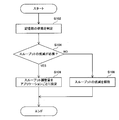
- FIG. 17 is a flowchart defining an operation procedure when the switch device adjusts the throughput of communication data transmitted from the in-vehicle device in the in-vehicle communication system according to the embodiment of the present invention.
- control unit 73 monitors L3 relay unit 71 and waits until L3 relay unit 71 receives an ACK frame (NO in step S202).
- the control unit 73 confirms whether or not a predetermined condition regarding the ACK frame is satisfied (step S204).
- the predetermined condition is, specifically, The L3 relay unit 71 is an ACK frame that is the same as the ACK frame that the corresponding in-vehicle device 111 and the application received this time, and the Ethernet header field, the IP header field, and the TCP header field are the same as the ACK frame that is received this time. It is whether or not a certain ACK frame is received three times in succession at intervals of a predetermined time or less.
- control unit 73 causes the L3 relay unit 71 to transmit the ACK frame received this time without delay regardless of the state of the storage unit 72 (step S206).
- control unit 73 causes the L3 relay unit 71 to transmit the ACK frame received this time according to the throughput adjustment amount (step S208).
- the control unit 73 compares the ACK frame received this time and the ACK frame received last time from the same vehicle-mounted device 111, and depending on the comparison result. Then, it is determined whether to delay the relay of the ACK frame received this time.
- the in-vehicle device 111 When the in-vehicle device 111 cannot normally receive the Ethernet frame transmitted from the other in-vehicle device 111, the in-vehicle device 111 requests the other in-vehicle device 111 to retransmit the Ethernet frame to the other in-vehicle device 111. May be transmitted multiple times in succession. In this case, with the configuration of the switch device 101 according to the modification, it is possible to prevent the retransmission of the Ethernet frame from being delayed.
- a switch device mounted on a vehicle A switch unit that relays communication data between a plurality of functional units mounted on the vehicle, A storage unit that holds the communication data to be relayed, A control unit that determines the state of the storage unit and, based on the determination result, adjusts the throughput of the communication data transmitted from the functional unit for each application, The control unit acquires the relay delay time by referring to a delay time table indicating the correspondence between the usage of the storage unit and the relay delay time for each application, and acquires the relay of the ACK frame by the switch unit.
- a switching device that adjusts the throughput by delaying the relay delay time.
- a switch device mounted on a vehicle A switch unit that relays communication data between a plurality of functional units mounted on the vehicle, A storage unit that holds the communication data to be relayed, A control unit that determines the state of the storage unit and, based on the determination result, adjusts the throughput of the communication data transmitted from the functional unit for each application, The control unit acquires the reduction amount by referring to a window size table indicating a correspondence relationship between the usage amount of the storage unit and the reduction amount of the window size for each application, and the ACK frame of the ACK frame received by the switch unit.
Landscapes
- Engineering & Computer Science (AREA)
- Computer Networks & Wireless Communication (AREA)
- Signal Processing (AREA)
- Quality & Reliability (AREA)
- Computer Security & Cryptography (AREA)
- Small-Scale Networks (AREA)
- Data Exchanges In Wide-Area Networks (AREA)
Abstract
スイッチ装置は、車両に搭載されるスイッチ装置であって、前記車両に搭載される複数の機能部間の通信データを中継するスイッチ部と、中継すべき前記通信データを保持する記憶部と、前記記憶部の状態を判定し、判定結果に基づいて、前記機能部から送信される前記通信データのスループットをアプリケーションごとに調整する制御部とを備える。
Description
本発明は、スイッチ装置、通信制御方法および通信制御プログラムに関する。
この出願は、2018年11月5日に出願された日本出願特願2018-208356号を基礎とする優先権を主張し、その開示のすべてをここに取り込む。
この出願は、2018年11月5日に出願された日本出願特願2018-208356号を基礎とする優先権を主張し、その開示のすべてをここに取り込む。
特許文献1(特開2013-168865号公報)には、以下のような車載ネットワークシステムが開示されている。すなわち、車載ネットワークシステムは、車載ネットワーク上で用いられる通信規約のうち前記車載ネットワーク上における実装に依拠する部分を定義する定義データを格納するメモリを備えた車載制御装置と、前記車載制御装置に対して前記定義データを発行する通信規約発行装置とを備える。前記通信規約発行装置は、前記車載制御装置を前記車載ネットワークに参加させる登録装置から、前記車載制御装置を前記車載ネットワークに参加させるよう要求する登録要求を受け取ると、前記登録装置に対する認証を実施した上で、前記車載ネットワークに上における実装に準拠した前記定義データを作成して前記登録装置に返信する。前記登録装置は、前記通信規約発行装置が送信した前記定義データを受け取り、受け取った前記定義データを前記メモリ上に格納するよう前記車載制御装置に対して要求する。そして、前記車載制御装置は、前記登録装置から定義データを受け取って前記メモリ上に格納し、前記定義データが定義する前記部分にしたがって、前記通信規約に準拠して前記車載ネットワークを用いて通信する。
(1)本開示のスイッチ装置は、車両に搭載されるスイッチ装置であって、前記車両に搭載される複数の機能部間の通信データを中継するスイッチ部と、中継すべき前記通信データを保持する記憶部と、前記記憶部の状態を判定し、判定結果に基づいて、前記機能部から送信される前記通信データのスループットをアプリケーションごとに調整する制御部とを備える。
(6)本開示の通信制御方法は、車両に搭載されるスイッチ装置であって中継すべき通信データを保持する記憶部を備えるスイッチ装置における通信制御方法であって、前記車両に搭載される複数の機能部間の通信データを中継するステップと、前記記憶部の状態を判定し、判定結果に基づいて、前記機能部から送信される前記通信データのスループットをアプリケーションごとに調整するステップとを含む。
(7)本開示の通信制御プログラムは、車両に搭載されるスイッチ装置であって中継すべき通信データを保持する記憶部を備えるスイッチ装置における通信制御プログラムであって、コンピュータを、前記車両に搭載される複数の機能部間の通信データを中継するスイッチ部と、前記記憶部の状態を判定し、判定結果に基づいて、前記機能部から送信される前記通信データのスループットをアプリケーションごとに調整する制御部、として機能させるためのプログラムである。
本開示の一態様は、このような特徴的な処理部を備えるスイッチ装置として実現され得るだけでなく、スイッチ装置を備える車載通信システムとして実現され得る。また、本開示の一態様は、スイッチ装置の一部または全部を実現する半導体集積回路として実現され得る。
従来、車載ネットワークにおけるセキュリティを向上させるための車載ネットワークシステムが開発されている。
[本開示が解決しようとする課題]
特許文献1に記載の車載ネットワークでは、車載ECU(Electronic Control Unit)間で送受信される通信データを中継する通信ゲートウェイが設けられる。
特許文献1に記載の車載ネットワークでは、車載ECU(Electronic Control Unit)間で送受信される通信データを中継する通信ゲートウェイが設けられる。
たとえば、通信ゲートウェイが車載ECUから多量の通信データを受信して輻輳状態となる場合がある。
本開示は、上述の課題を解決するためになされたもので、その目的は、車載ネットワークにおいてより安定した通信環境を実現することが可能なスイッチ装置、通信制御方法および通信制御プログラムを提供することである。
[本開示の効果]
本開示によれば、車載ネットワークにおいてより安定した通信環境を実現することができる。
本開示によれば、車載ネットワークにおいてより安定した通信環境を実現することができる。
[本願発明の実施形態の説明]
最初に、本発明の実施形態の内容を列記して説明する。
最初に、本発明の実施形態の内容を列記して説明する。
(1)本発明の実施の形態に係るスイッチ装置は、車両に搭載されるスイッチ装置であって、前記車両に搭載される複数の機能部間の通信データを中継するスイッチ部と、中継すべき前記通信データを保持する記憶部と、前記記憶部の状態を判定し、判定結果に基づいて、前記機能部から送信される前記通信データのスループットをアプリケーションごとに調整する制御部とを備える。
このような構成により、記憶部の状態に応じて、機能部から送信される通信データのスループットをアプリケーションごとに調整することができる。たとえば、スイッチ装置において輻輳状態となった場合に、アプリケーションの優先度に応じて通信データの送信を選択的に制限することができる。これにより、優先度が高いアプリケーションに関する通信データのスループットを大幅に低下させることなく、スイッチ装置の輻輳状態を緩和することができ、スイッチ装置における通信データの滞留および伝送遅延をバランス良く調整することができる。したがって、車載ネットワークにおいてより安定した通信環境を実現することができる。
(2)好ましくは、前記機能部は、他の前記機能部からACKを受信すると前記通信データを送信し、前記制御部は、前記スイッチ部による前記ACKの中継を遅延させることにより前記スループットを調整する。
このような構成により、制御部がACKの中継を遅延させることで、機能部による次の通信データの送信タイミングを遅延させることができる。これにより、既存の処理を利用しながら、スループットをアプリケーションごとに調整することができる。
(3)好ましくは、前記機能部は、他の前記機能部から受信した送信サイズ情報に応じた量の前記通信データを単位時間あたりで送信し、前記制御部は、前記スイッチ部が受信した前記送信サイズ情報の内容を変更して前記スイッチ部に中継させることにより前記スループットを調整する。
このような構成により、制御部が送信サイズ情報の内容を変更してスイッチ部に中継させることで、機能部が次に送信する通信データの量を調整することができる。これにより、既存の処理を利用しながら、スループットをアプリケーションごとに調整することができる。
(4)好ましくは、前記スイッチ装置は、さらに、複数の通信ポートを備え、前記スイッチ部は、前記通信ポートを介して前記通信データを送受信し、前記制御部は、前記通信ポートにおける前記通信データの送信レートに基づいて前記状態を判定する。
このような構成により、通信ポートにおける送信レートに基づいて記憶部の状態を事前に予測し、予測結果に基づいて記憶部の状態を判定することができる。これにより、たとえば、記憶部の容量が実際に不足する前に、機能部から送信される通信データのスループットをアプリケーションごとに調整することができる。
(5)好ましくは、前記制御部は、同じ前記機能部から今回受信した前記ACKおよび前回受信した前記ACKを比較し、比較結果に応じて、今回受信した前記ACKの中継を遅延させるか否かを決定する。
たとえば、機能部は、他の機能部から送信される通信データを正常に受信できなかった場合に、当該他の機能部に通信データの再送を要求するために当該他の機能部へACKを複数回連続で送信する場合がある。この場合、上記の構成により、通信データの再送が遅延することを防ぐことができる。
(6)本発明の実施の形態に係る通信制御方法は、車両に搭載されるスイッチ装置であって中継すべき通信データを保持する記憶部を備えるスイッチ装置における通信制御方法であって、前記車両に搭載される複数の機能部間の通信データを中継するステップと、前記記憶部の状態を判定し、判定結果に基づいて、前記機能部から送信される前記通信データのスループットをアプリケーションごとに調整するステップとを含む。
このような構成により、記憶部の状態に応じて、機能部から送信される通信データのスループットをアプリケーションごとに調整することができる。たとえば、スイッチ装置において輻輳状態となった場合に、アプリケーションの優先度に応じて通信データの送信を選択的に制限することができる。これにより、優先度が高いアプリケーションに関する通信データのスループットを大幅に低下させることなく、スイッチ装置の輻輳状態を緩和することができ、スイッチ装置における通信データの滞留および伝送遅延をバランス良く調整することができる。したがって、車載ネットワークにおいてより安定した通信環境を実現することができる。
(7)本発明の実施の形態に係る通信制御プログラムは、車両に搭載されるスイッチ装置であって中継すべき通信データを保持する記憶部を備えるスイッチ装置における通信制御プログラムであって、コンピュータを、前記車両に搭載される複数の機能部間の通信データを中継するスイッチ部と、前記記憶部の状態を判定し、判定結果に基づいて、前記機能部から送信される前記通信データのスループットをアプリケーションごとに調整する制御部、として機能させるためのプログラムである。
このような構成により、記憶部の状態に応じて、機能部から送信される通信データのスループットをアプリケーションごとに調整することができる。たとえば、スイッチ装置において輻輳状態となった場合に、アプリケーションの優先度に応じて通信データの送信を選択的に制限することができる。これにより、優先度が高いアプリケーションに関する通信データのスループットを大幅に低下させることなく、スイッチ装置の輻輳状態を緩和することができ、スイッチ装置における通信データの滞留および伝送遅延をバランス良く調整することができる。したがって、車載ネットワークにおいてより安定した通信環境を実現することができる。
以下、本発明の実施の形態について図面を用いて説明する。なお、図中同一または相当部分には同一符号を付してその説明は繰り返さない。また、以下に記載する実施の形態の少なくとも一部を任意に組み合わせてもよい。
[構成および基本動作]
図1は、本発明の実施の形態に係る車載通信システムの構成を示す図である。
図1は、本発明の実施の形態に係る車載通信システムの構成を示す図である。
図1を参照して、車載通信システム301は、スイッチ装置101と、複数の車載デバイス111とを備える。車載通信システム301は、車両1に搭載される。
以下、車載デバイス111A,111B,111C,111D,111Eの各々を、車載デバイス111とも称する。車載デバイス111は、機能部の一例である。なお、車載通信システム301は、5つの車載デバイス111を備える構成に限らず、2つ、3つ、4つまたは6つ以上の車載デバイス111を備える構成であってもよい。
車載デバイス111は、たとえば、自動運転ECU(Electronic Control Unit)、画像センサ、レーダ装置、ナビゲーション装置、TCU(Telematics Communication Unit)、セントラルゲートウェイ(CGW)、およびヒューマンマシンインタフェース等であり、スイッチ装置101と通信を行うことが可能である。
なお、車載デバイス111は、これらの具体例に限らず、車両1に搭載され、かつスイッチ装置101と通信可能な他のデバイスであってもよい。
スイッチ装置101および車載デバイス111は、たとえば、イーサネット(登録商標)ケーブル10により、互いに接続されている。車両1の車載ネットワークにおけるスイッチ装置101および各車載デバイス111の接続関係は、たとえば固定されている。
スイッチ装置101および車載デバイス111は、イーサネットケーブルを用いて互いに通信する。スイッチ装置101および車載デバイス111間では、たとえば、IEEE802.3に従うイーサネットフレームを用いて通信データのやり取りが行われる。
[車載デバイス]
車載デバイス111は、1または複数のアプリケーションの機能を有している。車載デバイス111は、自己のアプリケーションに関する情報を、スイッチ装置101を介して送受信する。
車載デバイス111は、1または複数のアプリケーションの機能を有している。車載デバイス111は、自己のアプリケーションに関する情報を、スイッチ装置101を介して送受信する。
車載デバイス111のアプリケーションの一例として、画像センサである車載デバイス111は、たとえば、車両1の周囲を周期的に撮影し、撮影結果を示す画像情報を作成する。
車載デバイス111のアプリケーションの他の例として、レーダ装置である車載デバイス111は、たとえば、ミリ波を用いて、車両1の周囲における歩行者等の物体の検知結果を示す検知情報を周期的に作成する。
車載デバイス111のアプリケーションの他の例として、自動運転ECUである車載デバイス111は、たとえば、画像センサから受けた画像情報およびレーダ装置から受けた検知情報に基づいて、自動運転を補助する。
図2は、本発明の実施の形態に係る車載通信システムにおける各装置のVID、MACアドレスおよびIPアドレスの一例を示す図である。
図2を参照して、車載ネットワークにおいて、たとえば、車載デバイス111A,111B,111Cと車載デバイス111D,111Eとは、互いに異なるVLAN(Virtual Local Area Network)に属する。
この例では、車載デバイス111A,111B,111Cの属するVLANのID(以下、VIDとも称する。)は、1である。また、車載デバイス111D,111Eの属するVIDは、2である。
スイッチ装置101および車載デバイス111は、固有のMAC(Media Access Control)アドレスおよびIP(Internet Protocol)アドレスを有する。
[スイッチ装置]
再び図1を参照して、スイッチ装置101は、車載ネットワークにおける複数の車載デバイス111間の通信データを中継する中継処理を行う。
再び図1を参照して、スイッチ装置101は、車載ネットワークにおける複数の車載デバイス111間の通信データを中継する中継処理を行う。
具体的には、車載ネットワークでは、たとえば、IPプロトコルに従って、IPパケットを用いて情報の送受信が行われる。IPパケットは、通信データの一例であるイーサネットフレームに格納されて伝送される。
スイッチ装置101は、各車載デバイス111間で伝送されるイーサネットフレームを中継する中継処理を行う。
詳細には、スイッチ装置101は、複数のレイヤを有する通信プロトコルに従って動作する。より詳細には、スイッチ装置101は、L2(レイヤ2)スイッチとして機能することが可能であり、同じVLANに属する車載デバイス111間のイーサネットフレームを中継する。また、スイッチ装置101は、L3(レイヤ3)中継装置としても機能することが可能であり、異なるVLANに属する車載デバイス111間のイーサネットフレームを中継する。
図3は、本発明の実施の形態に係る車載通信システムにおいて伝送されるイーサネットフレームの一例を示す図である。
図3を参照して、イーサネットフレームは、イーサネットヘッダフィールドと、IPヘッダフィールドと、TCPヘッダフィールドと、データフィールドと、CRC(Cyclic Redundancy Check)フィールドとを有する。
イーサネットヘッダフィールドには、送信先MACアドレスと、送信元MACアドレスと、タイプとが格納される。IPヘッダフィールドには、IPヘッダと、送信元IPアドレスと、送信先IPアドレスとが格納される。データフィールドには、任意のデータと、必要に応じてパディングとが格納される。CRCフィールドには、CRC値が格納される。
TCPヘッダフィールドには、送信先ポート番号と、送信元ポート番号と、シーケンス番号と、確認応答番号と、ヘッダ長およびセッションフラグと、ウィンドウサイズと、チェックサムと、緊急ポインタとが格納される。
ヘッダ長およびセッションフラグのフィールドには、ヘッダ長と、NS(Nonce Sum)フラグと、CWR(Congestion Window Reduced)フラグと、ESEフラグと、URG(Urgent)フラグと、ACK(Acknowledgement)フラグと、PSH(Push)フラグと、RST(Reset)フラグと、SYN(Synchronize)フラグと、FIN(Fin)フラグとが格納される。
たとえば、車載デバイス111Bが画像情報または検知情報を含むIPパケットを車載デバイス111Cへ送信する場合、このIPパケットには、送信元IPアドレスおよび送信先IPアドレスとして、IP-BおよびIP-Cがそれぞれ含まれる。
車載デバイス111Bは、自己と車載デバイス111Cとが同じVLANに属していることから、1、MAC-CおよびMAC-Bを、VID、送信先MACアドレスおよび送信元MACアドレスとしてそれぞれイーサネットフレームに書き込む。
車載デバイス111Bは、IPパケットを格納したイーサネットフレームをスイッチ装置101へ送信する。
スイッチ装置101は、車載デバイス111Bからイーサネットフレームを受信すると、受信したイーサネットフレームに対してレイヤ2のスイッチ処理を行うことで、当該イーサネットフレームを車載デバイス111Cへ送信する。
また、たとえば、車載デバイス111Bが画像情報または検知情報を含むIPパケットを車載デバイス111Dへ送信する場合、このIPパケットには、送信元IPアドレスおよび送信先IPアドレスとして、IP-BおよびIP-Dがそれぞれ含まれる。
車載デバイス111Bは、自己と車載デバイス111Dとが異なるVLANに属していることから、1、デフォルトゲートウェイであるスイッチ装置101のMACアドレスすなわちMAC-G、およびMAC-Bを、VID、送信先MACアドレスおよび送信元MACアドレスとしてそれぞれイーサネットフレームに書き込む。
車載デバイス111Bは、IPパケットを格納したイーサネットフレームをスイッチ装置101へ送信する。
スイッチ装置101は、車載デバイス111Bからイーサネットフレームを受信すると、受信したイーサネットフレームに対してレイヤ3の中継処理を行うことで、当該イーサネットフレームを車載デバイス111Dへ送信する。
そして、車載デバイス111Cまたは111Dは、スイッチ装置101を経由してイーサネットフレームを受信すると、ACKフラグを1に設定したイーサネットフレーム(以下、ACKフレームとも称する。)を車載デバイス111Bへ返信する。
車載デバイス111Bは、車載デバイス111Cまたは111DからACKフレームを受信すると、次のイーサネットフレームを車載デバイス111Cまたは111Dへ送信する。
車載デバイス111Cまたは111Dは、自己が次に受信可能なデータ量に関する送信サイズ情報を、車載デバイス111Bに通知する。車載デバイス111Bは、通知された送信サイズ情報に応じたデータ量のイーサネットフレームを単位時間あたりで送信する。
具体的には、たとえば、車載デバイス111Cまたは111Dは、送信サイズ情報たとえばウィンドウサイズが格納されたACKフレームを送信する。車載デバイス111Bは、ACKフレームを受信して、ACKフレームに格納されたウィンドウサイズに応じたデータ量を上限とするイーサネットフレームを、車載デバイス111Cまたは111Dへ送信する。
[スイッチ装置の構成]
図4は、本発明の実施の形態に係る車載通信システムにおけるスイッチ装置の構成を示す図である。
図4は、本発明の実施の形態に係る車載通信システムにおけるスイッチ装置の構成を示す図である。
図4を参照して、スイッチ装置101は、L2スイッチ処理部60と、L3中継処理部70と、通信ポート54である通信ポート54A,54B,54C,54D,54Eとを備える。
なお、スイッチ装置101では、5つの通信ポート54が設けられる構成に限らず、2つ、3つ、4つ、または6つ以上の通信ポート54が設けられる構成であってもよい。
通信ポート54は、たとえばイーサネットケーブル10を接続可能な端子である。なお、通信ポート54は、集積回路の端子であってもよい。
複数の通信ポート54の各々は、イーサネットケーブル10を介して複数の車載デバイス111のうちのいずれか1つに接続されている。また、複数の通信ポート54の各々は、たとえばVLANと対応付けられている。
L2スイッチ処理部60は、たとえば、L2スイッチとして動作し、同じVLANに属する車載デバイス111間のイーサネットフレームを中継する。
L3中継処理部70は、たとえば、L3スイッチとして動作し、異なるVLANに属する車載デバイス111間のイーサネットフレームを中継する。
図5は、本発明の実施の形態に係るスイッチ装置におけるL2スイッチ処理部の構成を示す図である。
図5を参照して、L2スイッチ処理部60は、L2スイッチ部61と、記憶部62とを含む。
L2スイッチ部61は、通信ポート54を介して受信したイーサネットフレームに対してレイヤ2のスイッチ処理を行う。L2スイッチ部61は、中継すべきイーサネットフレームを受信すると、受信したイーサネットフレームを記憶部62に保存する。
図6は、本発明の実施の形態に係るスイッチ装置におけるL3中継処理部の構成を示す図である。
図6を参照して、L3中継処理部70は、L3中継部71と、記憶部72と、制御部73と、タイマ74とを含む。
L3中継部71は、L2スイッチ部61から受信したイーサネットフレームに対してレイヤ3のスイッチ処理を行う。L3中継部71は、中継すべきイーサネットフレームを受信すると、受信したイーサネットフレームを記憶部72に保存する。記憶部72には、たとえば、アプリケーションごとのキューが設けられている。
図7は、本発明の実施の形態に係るスイッチ装置におけるL3中継処理部の記憶部に保存されるデータを示す図である。
図7を参照して、記憶部72には、あるアプリケーションに対応するキュー72Aと、別のアプリケーションに対応するキュー72Bとが設けられている。L3中継部71は、たとえば、イーサネットフレームに含まれる送信元ポート番号を参照することにより、対応のアプリケーションを特定し、イーサネットフレームをアプリケーションごとに対応のキューに振り分けて記憶部72に保存する。なお、記憶部72には3つ以上のキューが設けられている構成であってもよい。
制御部73は、記憶部72の状態を判定し、判定結果に基づいて、車載デバイス111から送信される通信データのスループットをアプリケーションごとに調整する。制御部73が通信データのスループットをアプリケーションごとに調整する方法の詳細については後述する。
[レイヤ2のスイッチ処理]
L2スイッチ部61は、たとえば、レイヤ2に従って、L3中継処理部70を介さずに中継処理を行うことが可能である。
L2スイッチ部61は、たとえば、レイヤ2に従って、L3中継処理部70を介さずに中継処理を行うことが可能である。
図5を参照して、L2スイッチ部61は、たとえば、L3中継処理部70および通信ポート54A,54B,54C,54D,54Eにそれぞれ接続される複数の端子を有する。各端子には、固有の論理ポート番号が割り当てられている。
この例では、L3中継処理部70および通信ポート54A,54B,54C,54D,54Eに接続された端子の論理ポート番号は、それぞれ#0、#1、#2、#3、#4および#5である。
また、L2スイッチ部61は、たとえば、ARLテーブル(Address Resolution Logic)を保持している。
ARLテーブルの内容は、上述したように車載ネットワークにおいて固定されている接続関係に基づいて、たとえばユーザにより予め定められている。
ARLテーブルは、たとえば、送信先MACアドレスと出力先との対応関係を示す。ここで、出力先は、論理ポート番号である。
具体的には、ARLテーブルには、車載デバイス111のMACアドレスと当該車載デバイス111を接続先とする端子の論理ポート番号との対応関係、および自己のスイッチ装置101のMACアドレスとL3中継処理部70の論理ポート番号との対応関係が含まれる。
L2スイッチ部61は、通信ポート54経由でイーサネットフレームを受信すると、受信したイーサネットフレームを記憶部62に保存するとともに、当該イーサネットフレームに含まれる送信先MACアドレスを取得する。
L2スイッチ部61は、取得した送信先MACアドレスに対応する論理ポート番号をARLテーブルから取得する。具体的には、L2スイッチ部61は、たとえば、車載デバイス111Bから車載デバイス111Cへ伝送されるイーサネットフレームのように、同一のVLAN内で伝送されるイーサネットフレームに対しては、取得した送信先MACアドレスに対応する論理ポート番号として、#1~#5のうちのいずれか1つを取得する。
そして、L2スイッチ部61は、対応のイーサネットフレームを記憶部62から取得し、取得したイーサネットフレームを、取得した論理ポート番号の端子から通信ポート54経由で車載デバイス111へ送信する。
一方、L2スイッチ部61は、たとえば、車載デバイス111Aから車載デバイス111Eへ伝送されるイーサネットフレームのように、異なるVLAN間で伝送されるイーサネットフレームに対しては、取得した送信先MACアドレスに対応する論理ポート番号として#0を取得する。
そして、L2スイッチ部61は、対応のイーサネットフレームを記憶部62から取得し、取得したイーサネットフレームをL3中継処理部70へ出力する。
[レイヤ3の中継処理]
L3中継部71は、L2スイッチ処理部60を介して中継処理を行う。具体的には、L3中継部71は、レイヤ2よりも上位のレイヤ3に従って中継処理行う。
L3中継部71は、L2スイッチ処理部60を介して中継処理を行う。具体的には、L3中継部71は、レイヤ2よりも上位のレイヤ3に従って中継処理行う。
L3中継部71は、L2スイッチ処理部60から受信したイーサネットフレームに対してレイヤ3の中継処理(以下、L3中継処理とも称する。)を行う。
詳細には、L3中継部71は、L2スイッチ処理部60からイーサネットフレームを受けて、受けたイーサネットフレームの送信先MACアドレスおよび送信元MACアドレスを書き換える。
より詳細には、L3中継部71は、たとえば、レイヤ3の中継処理に用いるIPアドレスとMACアドレスとの対応関係を示すテーブル情報TIAを保持する。
具体的には、L3中継部71は、自己が中継対象とする送信先ネットワークたとえばVLANとVIDとの対応関係を示すルーティングテーブル、およびVIDごとの、IPアドレスとMACアドレスとの対応関係を示すARP(Address Resolution Protocol)テーブルを含むテーブル情報TIAを保持する。
テーブル情報TIAの内容は、上述したように車載ネットワークにおいて固定されている接続関係に基づいて、たとえばユーザにより予め定められている。
L3中継部71は、L2スイッチ処理部60からイーサネットフレームを受けると、受けたイーサネットフレームを記憶部72に保存する。さらに、L3中継部71は、受けたイーサネットフレームに含まれるIPパケットから送信先IPアドレスを取得し、たとえば、取得した送信先IPアドレスに対してサブネットマスク計算を行うことによりVLANを特定する。
L3中継部71は、ルーティングテーブルを参照し、特定したVLANに対応するVIDを取得する。
そして、L3中継部71は、取得したVIDに対応するARPテーブルを参照し、送信先IPアドレスに対応するMACアドレスを当該ARPテーブルから取得する。
L3中継部71は、当該イーサネットフレームを記憶部72から取得し、取得したイーサネットフレームにおけるVID、送信先MACアドレスおよび送信元MACアドレスを、取得したVIDおよびMACアドレス、ならびに自己のスイッチ装置101のMACアドレスにそれぞれ書き換えてL2スイッチ処理部60へ出力する。
[L3中継処理の具体例]
図8は、本発明の実施の形態に係る車載通信システムにおける、L3中継処理されるイーサネットフレームの伝送経路の一例を示す図である。
図8は、本発明の実施の形態に係る車載通信システムにおける、L3中継処理されるイーサネットフレームの伝送経路の一例を示す図である。
図8を参照して、車載デバイス111Aが、たとえば、車載デバイス111Eを宛先とするイーサネットフレームを送信する状況を想定する。
この場合、車載デバイス111Aは、VID、送信元MACアドレス、送信先MACアドレスおよび送信先IPアドレスとして、1、MAC-A、MAC-GおよびIP-Eをそれぞれ含むイーサネットフレームをスイッチ装置101へ送信する。
スイッチ装置101におけるL3中継処理部70は、通信ポート54AおよびL2スイッチ処理部60経由で車載デバイス111Aからイーサネットフレームを受信すると、テーブル情報TIAに基づいて、受信したイーサネットフレームに対してL3中継処理を行う。
より詳細には、L3中継部71は、L2スイッチ処理部60からイーサネットフレームを受けて、受けたイーサネットフレームを記憶部72に保存する。そして、L3中継部71は、イーサネットフレームを記憶部72から取得し、取得したイーサネットフレームに含まれるVID、送信元MACアドレスおよび送信先MACアドレスを、2、MAC-GおよびMAC-Eにそれぞれ書き換える。L3中継部71は、書き換え後のイーサネットフレームをL2スイッチ処理部60へ出力する。
L2スイッチ処理部60は、L3中継処理部70からイーサネットフレームを受けると、ARLテーブルに基づいて、受けたイーサネットフレームに含まれる送信先MACアドレスに対応する論理ポート番号#5を取得する。
L2スイッチ処理部60は、取得した論理ポート番号#5の端子から通信ポート54E経由でイーサネットフレームを送信する。これにより、当該イーサネットフレームは、通信ポート54E経由で車載デバイス111Eへ送信される。
[課題]
ところで、スイッチ装置101が車載デバイス111から多量の通信データたとえばイーサネットフレームを受信すると、たとえば、L3中継処理部70の記憶部72においてオーバーフローが生じる場合がある。
ところで、スイッチ装置101が車載デバイス111から多量の通信データたとえばイーサネットフレームを受信すると、たとえば、L3中継処理部70の記憶部72においてオーバーフローが生じる場合がある。
記憶部72のオーバーフローを解消するために、たとえば、スイッチ装置101から車載デバイス111へポーズフレームを送信することにより、車載デバイス111からイーサネットフレームが送信されてくる頻度を下げることが考えられる。
たとえば、イーサネットフレームの送信元の車載デバイス111の別に応じて優先度を設定しておき、優先度の低い車載デバイス111へポーズフレームを送信する。
これにより、優先度の低い車載デバイス111からイーサネットフレームが送信されてくる頻度を下げ、優先度の高い車載デバイス111からのイーサネットフレームを優先的に中継することができるため、記憶部72がオーバーフロー状態となる可能性を低減することができる。
しかしながら、車載デバイス111が複数のアプリケーションの機能を有している場合、アプリケーションの優先度に応じて、優先度の高いアプリケーションに対応するイーサネットフレームを優先的に中継することはできない。
[スループットの調整]
[スループットの調整]
制御部73は、記憶部72の状態を判定する。より詳細には、制御部73は、記憶部72を定期的または不定期に監視し、記憶部72が保持しているデータの量またはイーサネットフレームの数を参照することにより記憶部72の状態を判定する。なお、制御部73は、L3中継部71を監視し、L3中継部71がL2スイッチ処理部60からイーサネットフレームを受信すると、記憶部72が保持しているデータの量またはイーサネットフレームの数を参照することにより記憶部72の状態を判定してもよい。
制御部73は、判定した結果に基づいて、車載デバイス111から送信される通信データのスループットをアプリケーションごとに調整する。通信データのスループットは、ウィンドウサイズをRTT(Round Trip Time)で除した値に比例する。
[動作の流れ]
車載通信システム301における各装置は、メモリを含むコンピュータを備え、当該コンピュータにおけるCPU等の演算処理部は、以下のフローチャートおよびシーケンスの各ステップの一部または全部を含むプログラムを当該メモリからそれぞれ読み出して実行する。これら複数の装置のプログラムは、それぞれ、外部からインストールすることができる。これら複数の装置のプログラムは、それぞれ、記録媒体に格納された状態で流通する。
車載通信システム301における各装置は、メモリを含むコンピュータを備え、当該コンピュータにおけるCPU等の演算処理部は、以下のフローチャートおよびシーケンスの各ステップの一部または全部を含むプログラムを当該メモリからそれぞれ読み出して実行する。これら複数の装置のプログラムは、それぞれ、外部からインストールすることができる。これら複数の装置のプログラムは、それぞれ、記録媒体に格納された状態で流通する。
[ACKフレームの中継保留]
たとえば、スイッチ装置101は、送信先の車載デバイス111からのACKの中継を遅延させることにより、車載デバイス111間のRTTを増大させることで通信データのスループットをアプリケーションごとに調整する。
たとえば、スイッチ装置101は、送信先の車載デバイス111からのACKの中継を遅延させることにより、車載デバイス111間のRTTを増大させることで通信データのスループットをアプリケーションごとに調整する。
たとえば、スイッチ装置101は、送信先の車載デバイス111から受信したACKフレームの中継を遅延させる。より詳細には、制御部73は、L3中継部71によるACKフレームの送信タイミングを遅延させる。
再び図8を参照して、たとえば、車載デバイス111Aが2つのアプリケーション1,2を有しており、各アプリケーションに対応するイーサネットフレームを車載デバイス111Eへ送信する状況を想定する。
ここでは、アプリケーション1の優先度はアプリケーション2の優先度よりも高く、アプリケーション1に対応するイーサネットフレームF1はアプリケーション2に対応するイーサネットフレームF2よりも優先的に中継されて車載デバイス111Eへ送信される必要があるものとする。
制御部73は、記憶部72の状態に応じて、L3中継部71によるACKフレームの送信タイミングの遅延時間(以下、中継遅延時間とも称する。)を決定し、ACKフレームを中継するタイミングを調整する。
図9は、本発明の実施の形態に係るスイッチ装置における制御部が保持している遅延時間テーブルの一例を示す図である。
図9を参照して、たとえば、制御部73は、記憶部72が保持しているデータの量(以下、記憶部72の使用量とも称する。)Cと中継遅延時間Tとのアプリケーションごとの対応関係を示す遅延時間テーブルを保持しており、遅延時間テーブルを参照することにより中継遅延時間を決定する。
具体的には、たとえば、記憶部72の使用量C1が1000kバイト以上1500kバイト未満の状態におけるアプリケーション1の中継遅延時間T1は10ミリ秒であり、アプリケーション2の中継遅延時間T2は20ミリ秒である。また、たとえば、記憶部72の使用量C1が1500kバイト以上2000kバイト未満の状態におけるアプリケーション1の中継遅延時間T1は15ミリ秒であり、アプリケーション2の中継遅延時間T2は30ミリ秒である。
すなわち、制御部73は、記憶部72の使用量C1が1000kバイト以上の場合には、L3中継部71によるACKフレームの送信タイミングを遅延させる必要があると判断し、記憶部72の使用量C1が1000kバイト未満の場合には、L3中継部71によるACKフレームの送信タイミングを遅延させる必要がないと判断する。
図10は、本発明の実施の形態に係るスイッチ装置における記憶部の使用量とACKフレームの遅延時間との関係の一例を示す図である。図10において、縦軸は中継遅延時間(秒)を示し、横軸は記憶部の使用量(byte)を示す。
図10を参照して、制御部73が保持する遅延時間テーブルは、記憶部72の使用量Cが所定の値であるC0以上の場合において、中継遅延時間Tが記憶部72の使用量Cに比例し、かつ、アプリケーションの優先度が低いほど記憶部72の使用量Cの増加に対する中継遅延時間Tの増加量が大きくなるように設定されている。
図11は、本発明の実施の形態に係る車載通信システムにおける、通信データのスループット調整のシーケンスの一例を示す図である。
図11を参照して、まず、スイッチ装置101において、制御部73は、所定のタイミングにおいて記憶部72の状態を判定する(ステップS11)。
次に、制御部73は、記憶部72の状態を判定した結果、L3中継部71によるACKフレームの送信タイミングを遅延させる必要があると判断すると、アプリケーションごとに中継遅延時間Tを設定する。具体的には、制御部73は、遅延時間テーブルを参照することにより中継遅延時間Tを設定する(ステップS12)。
次に、車載デバイス111Aは、アプリケーション1に対応するイーサネットフレームF1を、スイッチ装置101を介して車載デバイス111Eへ送信する(ステップS13)。
次に、車載デバイス111Aは、アプリケーション2に対応するイーサネットフレームF2を、スイッチ装置101を介して車載デバイス111Eへ送信する(ステップS14)。
次に、車載デバイス111Eは、イーサネットフレームF1を受信すると、イーサネットフレームF1に対するACKフレームackF1をスイッチ装置101へ送信する(ステップS15)。
次に、車載デバイス111Eは、イーサネットフレームF2を受信すると、イーサネットフレームF2に対するACKフレームackF2をスイッチ装置101へ送信する(ステップS16)。
次に、スイッチ装置101は、ACKフレームackF1を受信すると、ACKフレームackF1の転送を中継遅延時間T1だけ保留し(ステップS17)、車載デバイス111Aへ送信する(ステップS18)。
次に、車載デバイス111Aは、ACKフレームackF1を受信すると、次に送信すべきイーサネットフレームF1を、スイッチ装置101を介して車載デバイス111Eへ送信する(ステップS19)。
一方、スイッチ装置101は、ACKフレームackF2を受信すると、ACKフレームackF2の転送を中継遅延時間T2だけ保留し(ステップS20)、車載デバイス111Aへ送信する(ステップS21)。
次に、車載デバイス111Aは、ACKフレームackF2を受信すると、次に送信すべきイーサネットフレームF2を、スイッチ装置101を介して車載デバイス111Eへ送信する(ステップS22)。
次に、制御部73は、前回記憶部72の状態を判定したタイミングから所定時間経過後の所定のタイミングにおいて記憶部72の状態を判定する(ステップS23)。
次に、制御部73は、記憶部72の状態を判定した結果、L3中継部71によるACKフレームの送信タイミングを遅延させる必要がないと判断すると、中継遅延時間Tの設定を解除する(ステップS24)。
次に、車載デバイス111Aは、アプリケーション1に対応するイーサネットフレームF1を、スイッチ装置101を介して車載デバイス111Eへ送信する(ステップS25)。
次に、車載デバイス111Eは、イーサネットフレームF1を受信すると、イーサネットフレームF1に対するACKフレームackF1をスイッチ装置101へ送信する(ステップS26)。
次に、スイッチ装置101は、ACKフレームackF1を受信すると、ACKフレームackF1の中継を保留することなく、車載デバイス111Aへ送信する(ステップS27)。
次に、車載デバイス111Aは、アプリケーション2に対応するイーサネットフレームF1を、スイッチ装置101を介して車載デバイス111Eへ送信する(ステップS28)。
次に、車載デバイス111Eは、イーサネットフレームF2を受信すると、イーサネットフレームF2に対するACKフレームackF2をスイッチ装置101へ送信する(ステップS29)。
次に、スイッチ装置101は、ACKフレームackF2を受信すると、ACKフレームackF2の中継を保留することなく、車載デバイス111Aへ送信する(ステップS30)。
より詳細には、ステップS17において、スイッチ装置101におけるL3中継部71は、L2スイッチ処理部60を介してACKフレームackF1を受信すると、受信したACKフレームackF1を記憶部72に保存する。制御部73は、L3中継部71がACKフレームackF1を受信すると、設定している中継遅延時間T1をタイマ74にセットする。
タイマ74にセットした中継遅延時間T1が経過すると、制御部73は、タイマ74からの中継遅延時間T1が経過した旨の通知を受けて、中継遅延時間T1の経過をL3中継部71に通知する。L3中継部71は、制御部73からの通知を受けて、ACKフレームackF1を記憶部72から取得し、取得したACKフレームackF1に含まれるVID等を書き換えてL2スイッチ処理部60へ出力する。
また、ステップS20において、スイッチ装置101におけるL3中継部71は、L2スイッチ処理部60を介してACKフレームackF2を受信すると、受信したACKフレームackF2を記憶部72に保存する。制御部73は、L3中継部71がACKフレームackF2を受信すると、設定している中継遅延時間T2をタイマ74にセットする。
タイマ74にセットした中継遅延時間T2が経過すると、制御部73は、タイマ74からの中継遅延時間T2が経過した旨の通知を受けて、中継遅延時間T2の経過をL3中継部71に通知する。L3中継部71は、制御部73からの通知を受けて、ACKフレームackF2を記憶部72から取得し、取得したACKフレームackF2に含まれるVID等を書き換えてL2スイッチ処理部60へ出力する。
このようにして、スイッチ装置101は、記憶部72の使用量に応じて、ACKフレームを宛先の車載デバイス111へ送信するタイミングを調整する。
[ウィンドウサイズの変更]
たとえば、スイッチ装置101は、送信先の車載デバイス111から受信した送信サイズ情報の内容を変更することにより、送信元の車載デバイス111が次回送信する通信データの単位時間あたりのデータ量を調整することで通信データのスループットをアプリケーションごとに調整する。
たとえば、スイッチ装置101は、送信先の車載デバイス111から受信した送信サイズ情報の内容を変更することにより、送信元の車載デバイス111が次回送信する通信データの単位時間あたりのデータ量を調整することで通信データのスループットをアプリケーションごとに調整する。
たとえば、スイッチ装置101は、送信先の車載デバイス111から受信したACKフレームにおけるウィンドウサイズを変更する。より詳細には、制御部73は、ACKフレームにおけるウィンドウサイズをL3中継部71に変更させる。
制御部73は、記憶部72の状態に応じてウィンドウサイズの縮小量を決定し、次回送信されるイーサネットフレームのデータ量を調整する。
図12は、本発明の実施の形態に係るスイッチ装置における制御部が保持しているウィンドウサイズテーブルの一例を示す図である。
図12を参照して、たとえば、制御部73は、記憶部72の使用量Cとウィンドウサイズの縮小量Wとのアプリケーションごとの対応関係を示すウィンドウサイズテーブルを保持しており、ウィンドウサイズテーブルを参照することにより、ウィンドウサイズの縮小量Wを決定し、次回送信されるイーサネットフレームのデータ量の上限を調整する。
具体的には、たとえば、記憶部72の使用量C1が1000kバイト以上1500kバイト未満の状態におけるアプリケーション1のウィンドウサイズの縮小量W1は1000バイトであり、アプリケーション2のウィンドウサイズの縮小量W2は2000バイトである。また、たとえば、記憶部72の使用量C1が1500kバイト以上2000kバイト未満の状態におけるアプリケーション1のウィンドウサイズの縮小量W1は1500バイトであり、アプリケーション2のウィンドウサイズの縮小量W2は3000バイトである。
図13は、本発明の実施の形態に係るスイッチ装置における記憶部の使用量とウィンドウサイズの縮小量との関係の一例を示す図である。図13において、縦軸はウィンドウサイズの縮小量(byte)を示し、横軸は記憶部の使用量(byte)を示す。
すなわち、制御部73は、記憶部72の使用量C1が1000kバイト以上の場合には、ウィンドウサイズを縮小させる必要があると判断し、記憶部72の使用量C1が1000kバイト未満の場合には、ウィンドウサイズを縮小させる必要があると判断する。
図13を参照して、制御部73が保持するウィンドウサイズテーブルは、記憶部72の使用量Cが所定の値C0以上の場合において、ウィンドウサイズの縮小量Wが記憶部72の使用量Cに比例し、かつ、アプリケーションの優先度が低いほど記憶部72の使用量Cの増加に対するウィンドウサイズの縮小量Wの増加量が大きくなるように設定されている。
図14は、本発明の実施の形態に係る車載通信システムにおける、通信データのスループット調整のシーケンスの一例を示す図である。
図14を参照して、まず、スイッチ装置101において、制御部73は、所定のタイミングにおいて記憶部72の状態を判定する(ステップS31)。
次に、制御部73は、記憶部72の状態を判定した結果、ウィンドウサイズを縮小させる必要があると判断すると、アプリケーションごとにウィンドウサイズの縮小量Wを設定する。具体的には、制御部73は、ウィンドウサイズテーブルを参照することにより縮小量Wを決定する(ステップS32)。
次に、車載デバイス111Aは、アプリケーション1に対応するイーサネットフレームF1を、スイッチ装置101を介して車載デバイス111Eへ送信する(ステップS33)。
次に、車載デバイス111Eは、イーサネットフレームF1を受信すると、イーサネットフレームF1に対するACKフレームackF1をスイッチ装置101へ送信する(ステップS34)。
次に、スイッチ装置101は、ACKフレームackF1を受信すると、ACKフレームackF1のTCPヘッダフィールドに含まれるウィンドウサイズを書き換え(ステップS35)、書き換え後のACKフレームackF1を車載デバイス111Aへ送信する(ステップS36)。
次に、車載デバイス111Aは、ACKフレームackF1を受信すると、ACKフレームackF1のTCPヘッダフィールドに含まれるウィンドウサイズで指定されたデータ量を上限として、次に送信すべきイーサネットフレームF1を、スイッチ装置101を介して車載デバイス111Eへ送信する(ステップS37)。
次に、車載デバイス111Aは、アプリケーション2に対応するイーサネットフレームF2を、スイッチ装置101を介して車載デバイス111Eへ送信する(ステップS38)。
次に、車載デバイス111Eは、イーサネットフレームF2を受信すると、イーサネットフレームF2に対するACKフレームackF2をスイッチ装置101へ送信する(ステップS39)。
次に、スイッチ装置101は、ACKフレームackF2を受信すると、ACKフレームackF2のTCPヘッダフィールドに含まれるウィンドウサイズを書き換え(ステップS40)、書き換え後のACKフレームackF2を車載デバイス111Aへ送信する(ステップS41)。
次に、車載デバイス111Aは、ACKフレームackF2を受信すると、ACKフレームackF1のTCPヘッダフィールドに含まれるウィンドウサイズで指定されたデータ量を上限として、次に送信すべきイーサネットフレームF2を、スイッチ装置101を介して車載デバイス111Eへ送信する(ステップS42)。
次に、制御部73は、前回記憶部72の状態を判定したタイミングから所定時間経過後の所定のタイミングにおいて記憶部72の状態を判定する(ステップS43)。
次に、制御部73は、記憶部72の状態を判定した結果、ウィンドウサイズを縮小させる必要がないと判断すると、ウィンドウサイズの縮小量Wの設定を解除する(ステップS44)。
次に、車載デバイス111Aは、アプリケーション1に対応するイーサネットフレームF1を、スイッチ装置101を介して車載デバイス111Eへ送信する(ステップS45)。
次に、車載デバイス111Eは、イーサネットフレームF1を受信すると、イーサネットフレームF1に対するACKフレームackF1をスイッチ装置101へ送信する(ステップS46)。
次に、スイッチ装置101は、ACKフレームackF1を受信すると、ACKフレームackF1に含まれるウィンドウサイズを書き換えることなく、車載デバイス111Aへ送信する(ステップS47)。
次に、車載デバイス111Aは、アプリケーション2に対応するイーサネットフレームF1を、スイッチ装置101を介して車載デバイス111Eへ送信する(ステップS48)。
次に、車載デバイス111Eは、イーサネットフレームF2を受信すると、イーサネットフレームF2に対するACKフレームackF2をスイッチ装置101へ送信する(ステップS49)。
次に、スイッチ装置101は、ACKフレームackF2を受信すると、ACKフレームackF2に含まれるウィンドウサイズを書き換えることなく、車載デバイス111Aへ送信する(ステップS50)。
より詳細には、ステップS35において、スイッチ装置101におけるL3中継部71は、L2スイッチ処理部60を介してACKフレームackF1を受信すると、受信したACKフレームackF1を記憶部72に保存する。制御部73は、L3中継部71がACKフレームackF1を受信すると、設定しているウィンドウサイズの縮小量W1をL3中継部71に通知する。
L3中継部71は、ACKフレームackF1を記憶部72から取得し、ACKフレームackF1に含まれるウィンドウサイズを縮小量W1に従って書き換えるとともに、ACKフレームackF1に含まれるVID等を書き換えてL2スイッチ処理部60へ出力する。
また、ステップS40において、スイッチ装置101におけるL3中継部71は、L2スイッチ処理部60を介してACKフレームackF2を受信すると、受信したACKフレームackF2を記憶部72に保存する。制御部73は、L3中継部71がACKフレームackF1を受信すると、設定しているウィンドウサイズの縮小量W2をL3中継部71に通知する。
L3中継部71は、ACKフレームackF2を記憶部72から取得し、ACKフレームackF2に含まれるウィンドウサイズを縮小量W2に従って書き換えるとともに、ACKフレームackF2に含まれるVID等を書き換えてL2スイッチ処理部60へ出力する。
このようにして、スイッチ装置101は、記憶部72の使用量に応じて、車載デバイス111Aが次に送信するイーサネットフレームのデータ量を調整する。
[送信レートからの推測]
スイッチ装置101では、制御部73は、通信ポート54における通信データの送信レートに基づいて、記憶部72の状態を判定してもよい。
スイッチ装置101では、制御部73は、通信ポート54における通信データの送信レートに基づいて、記憶部72の状態を判定してもよい。
より詳細には、制御部73は、少なくともいずれか1つの通信ポート54を定期的または不定期に監視し、通信ポート54における通信データの送信レートに基づいて、記憶部72の状態を判定する。
たとえば、制御部73は、各通信ポート54を監視し、たとえば平均送信レートが最大である通信ポートの送信レート(以下、最大送信レートとも称する。)に基づいて、記憶部72の状態を判定する。あるいは、制御部73は、各通信ポート54を監視し、各通信ポートの送信レートの平均値に基づいて、記憶部72の状態を判定する。
図15は、本発明の実施の形態に係るスイッチ装置における制御部が保持している使用量推測テーブルの一例を示す図である。
図15を参照して、たとえば、制御部73は、最大送信レートと所定時間後の記憶部72の使用量との対応関係を示す使用量推測テーブルを保持している。制御部73は、使用量推測テーブルを参照することにより、所定時間後の記憶部72の使用量を推測する。
具体的には、たとえば、制御部73は、最大送信レートが50Mbps未満の場合、所定時間後の記憶部72の使用量の推定値を500kbyte未満であると推測し、最大送信レートが50Mbps以上の場合、所定時間後の記憶部72の使用量の推定値を500kbyte以上1000kbyte未満であると推測し、最大送信レートが75Mbps以上の場合、所定時間後の記憶部72の使用量の推定値を1000kbyte以上1500kbyte未満であると推測し、最大送信レートが100Mbps以上の場合、所定時間後の記憶部72の使用量の推定値を1500kbyte以上2000kbyte未満であると推測する。
制御部73は、上記推測結果に基づいて記憶部72の状態を判定し、通信データのスループットをアプリケーションごとに調整する。
より詳細には、制御部73は、推測した記憶部72の使用量に基づいて、図9に示す遅延時間テーブルを参照することにより中継遅延時間Tを決定する。あるいは、制御部73は、推測した記憶部72の使用量に基づいて、図12に示すウィンドウサイズテーブルを参照することによりウィンドウサイズの縮小量Wを決定する。
[動作の流れ]
図16は、本発明の実施の形態に係る車載通信システムにおいて、スイッチ装置が車載デバイスから送信される通信データのスループットを調整する際の動作手順を定めたフローチャートである。
図16は、本発明の実施の形態に係る車載通信システムにおいて、スイッチ装置が車載デバイスから送信される通信データのスループットを調整する際の動作手順を定めたフローチャートである。
図16を参照して、制御部73は、記憶部72の状態を定期的または不定期に判定する(ステップS102)。具体的には、制御部73は、記憶部72を定期的または不定期に監視し、記憶部72が保持しているデータの量またはイーサネットフレームの数に基づいて記憶部72の状態を判定する。あるいは、制御部73は、通信ポート54を定期的または不定期に監視し、通信ポート54における通信データの送信レートに基づいて記憶部72の状態を判定する。
次に、制御部73は、記憶部72の状態の判定結果に基づいて、通信データのスループットを低減する必要があるかを判断する(ステップS104)。たとえば、図9に示す遅延時間テーブルまたは図12に示すウィンドウサイズテーブルを参照することにより、通信データのスループットを低減する必要があるかを判断する。
次に、制御部73は、通信データのスループットを低減する必要があると判断した場合(ステップS104でYES)、スループットの低減量をアプリケーションごとに設定する(ステップS106)。たとえば、制御部73は、記憶部72の状態に応じて中継遅延時間Tまたはウィンドウサイズの縮小量Wをアプリケーションごとに設定する。
一方、制御部73は、通信データのスループットを低減する必要がないと判断した場合(ステップS104でNO)、スループットの低減を解除する(ステップS108)。たとえば、制御部73は、中継遅延時間Tまたはウィンドウサイズの縮小量Wの設定を解除する。
なお、本発明の実施の形態に係る車載通信システムでは、制御部73は、記憶部72の状態に応じて、ACKフレームの送信タイミングの遅延および送信サイズ情報の内容の変更のうち、いずれか一方のみを行う構成であってもよいし、両方を行う構成であってもよい。
また、本発明の実施の形態に係る車載通信システムでは、1つの車載デバイス111が2つのアプリケーションを有しており、スイッチ装置101は、各アプリケーションに対応するイーサネットフレームを他の車載デバイス111へ送信する場合に通信データのスループットをアプリケーションごとに調整する構成であるとしたが、これに限定するものではない。
制御部73は、1つの車載デバイス111が有するアプリケーションに対応するイーサネットフレームと、他の車載デバイス111が有するアプリケーションに対応するイーサネットフレームとを、さらに他の車載デバイス111へ送信する場合に通信データのスループットをアプリケーションごとに調整する構成であってもよい。
また、本発明の実施の形態に係る車載通信システムでは、L3中継処理部70が制御部73を有しており、制御部73が、記憶部72の状態を判定し、判定結果に基づいて、車載デバイスから送信される通信データのスループットをアプリケーションごとに調整する構成であるとしたが、これに限定するものではない。
制御部73が、上記判定結果に基づいて、図9に示す遅延時間テーブルを参照することにより中継遅延時間Tを決定し、L2スイッチ処理部60におけるL2スイッチ部61によるACKフレームの送信タイミングを遅延させることにより、通信データのスループットをアプリケーションごとに調整する構成であってもよい。さらに、制御部73が、上記判定結果に基づいて、図12に示すウィンドウサイズテーブルを参照することにより縮小量Wを決定し、L2スイッチ部61に送信サイズ情報の内容を変更させることにより、通信データのスループットをアプリケーションごとに調整する構成であってもよい。
さらに、制御部73が、L2スイッチ処理部60における記憶部62の状態を判定し、判定結果に基づいて、L3中継部71またはL2スイッチ部61によるACKフレームの送信タイミングを遅延させることにより、通信データのスループットをアプリケーションごとに調整する構成であってもよい。あるいは、制御部73が、L2スイッチ処理部60における記憶部62の状態を判定し、判定結果に基づいて、L3中継部71またはL2スイッチ部61に送信サイズ情報の内容を変更させることにより、通信データのスループットをアプリケーションごとに調整する構成であってもよい。
また、本発明の実施の形態に係る車載通信システムでは、スイッチ装置101は、2つのアプリケーションに対応する各イーサネットフレームを他の車載デバイス111へ送信する場合に、いずれのアプリケーションについても通信データのスループットを調整する構成であるとしたが、これに限定するものではない。スイッチ装置101は、制御部73が記憶部72の状態を判定した結果、一方のアプリケーションについては通信データのスループットを調整せず、他方のアプリケーションについてのみ通信データのスループットを調整する構成であってもよい。また、スイッチ装置101は、3つ以上のアプリケーションに対応する各イーサネットフレームを他の車載デバイス111へ送信する場合に、少なくともいずれか1つのアプリケーションについて通信データのスループットを調整する構成であってもよい。
ところで、特許文献1に記載の車載ネットワークでは、車載ECU(Electronic Control Unit)間で送受信される通信データを中継する通信ゲートウェイが設けられる。
たとえば、通信ゲートウェイが車載ECUから多量の通信データを受信して輻輳状態となる場合がある。
具体的には、たとえば、車載ネットワークにおいて、スイッチ装置101が車載デバイス111から多量の通信データたとえばイーサネットフレームを受信すると、たとえば、L3中継処理部70の記憶部においてオーバーフローが生じる場合がある。
記憶部のオーバーフローを解消するために、たとえば、スイッチ装置101から車載デバイス111へポーズフレームを送信することにより、車載デバイスからイーサネットフレームが送信されてくる頻度を下げることが考えられる。
しかしながら、車載デバイス111が複数のアプリケーションの機能を有している場合、アプリケーションの優先度に応じて、優先度の高いアプリケーションに対応するイーサネットフレームを優先的に中継することはできない。
これに対して、本発明の実施の形態に係るスイッチ装置101では、車両1に搭載される。L3中継部71は、車両1に搭載される複数の車載デバイス111間のイーサネットフレームを中継する。記憶部72は、中継すべきイーサネットフレームを保持する。そして、制御部73は、記憶部72の状態を判定し、判定結果に基づいて、車載デバイス111から送信されるイーサネットフレームのスループットをアプリケーションごとに調整する。
このような構成により、記憶部72の状態に応じて、車載デバイス111から送信されるイーサネットフレームのスループットをアプリケーションごとに調整することができる。たとえば、スイッチ装置101において輻輳状態となった場合に、アプリケーションの優先度に応じてイーサネットフレームの送信を選択的に制限することができる。これにより、優先度が高いアプリケーションに関するイーサネットフレームのスループットを大幅に低下させることなく、スイッチ装置101の輻輳状態を緩和することができ、スイッチ装置101におけるイーサネットフレームの滞留および伝送遅延をバランス良く調整することができる。
したがって、本発明の実施の形態に係るスイッチ装置101では、車載ネットワークにおいてより安定した通信環境を実現することができる。
また、本発明の実施の形態に係るスイッチ装置101では、車載デバイス111は、他の車載デバイス111からACKフレームを受信するとイーサネットフレームを送信する。制御部73は、L3中継部71によるACKフレームの中継を遅延させることによりスループットを調整する。
このような構成により、制御部73がACKフレームの中継を遅延させることで、車載デバイス111による次のイーサネットフレームの送信タイミングを遅延させることができる。これにより、既存の処理を利用しながら、スループットをアプリケーションごとに調整することができる。
また、本発明の実施の形態に係るスイッチ装置101では、車載デバイス111は、他の車載デバイス111から受信したACKフレームにおけるウィンドウサイズに応じた量のイーサネットフレームを単位時間あたりで送信する。制御部73は、L3中継部71が受信したACKフレームにおけるウィンドウサイズの内容を変更してL3中継部71に中継させることによりスループットを調整する。
このような構成により、制御部73がACKフレームにおけるウィンドウサイズの内容を変更してL3中継部71に中継させることで、車載デバイス111が次に送信するイーサネットフレームの量を調整することができる。これにより、既存の処理を利用しながら、スループットをアプリケーションごとに調整することができる。
また、本発明の実施の形態に係るスイッチ装置101は、複数の通信ポート54を備える。L3中継部71は、通信ポート54を介してイーサネットフレームを送受信する。そして、制御部73は、通信ポート54におけるイーサネットフレームの送信レートに基づいて記憶部72の状態を判定する。
このような構成により、通信ポート54における送信レートに基づいて記憶部72の状態を事前に予測し、予測結果に基づいて記憶部72の状態を判定することができる。これにより、たとえば、記憶部72の容量が実際に不足する前に、車載デバイス111から送信されるイーサネットフレームのスループットをアプリケーションごとに調整することができる。
本発明の実施の形態に係る通信制御方法では、まず、スイッチ装置101が、車両1に搭載される複数の車載デバイス111間のイーサネットフレームを中継する。次に、スイッチ装置101が、記憶部72の状態を判定し、判定結果に基づいて、車載デバイス111から送信されるイーサネットフレームのスループットをアプリケーションごとに調整する。
このような方法により、記憶部72の状態に応じて、車載デバイス111から送信されるイーサネットフレームのスループットをアプリケーションごとに調整することができる。たとえば、スイッチ装置101において輻輳状態となった場合に、アプリケーションの優先度に応じてイーサネットフレームの送信を選択的に制限することができる。これにより、優先度が高いアプリケーションに関するイーサネットフレームのスループットを大幅に低下させることなく、スイッチ装置101の輻輳状態を緩和することができ、スイッチ装置101におけるイーサネットフレームの滞留および伝送遅延をバランス良く調整することができる。
したがって、本発明の実施の形態に係る通信制御方法では、車載ネットワークにおいてより安定した通信環境を実現することができる。
[スイッチ装置101の変形例1]
再び図1を参照して、車載デバイス111は、イーサネットフレームを正常に受信できなかった場合、イーサネットフレームの再送を要求するために、同一のACKフレームを3回連続で送信元の車載デバイス111へ送信する。
再び図1を参照して、車載デバイス111は、イーサネットフレームを正常に受信できなかった場合、イーサネットフレームの再送を要求するために、同一のACKフレームを3回連続で送信元の車載デバイス111へ送信する。
より詳細には、車載デバイス111は、イーサネットフレームを正常に受信できなかった場合、イーサネットヘッダフィールド、IPヘッダフィールド、およびTCPヘッダフィールドが同一であるACKフレームを3回連続で送信元の車載デバイス111へ送信する。
車載デバイス111は、同一のACKフレームを所定時間内に3回連続で受信すると、前回送信したイーサネットフレームを再送する。
このような構成においては、記憶部72の状態に関わらず、送信元の車載デバイス111によるイーサネットフレームの再送は遅滞なく行われることが好ましい。
そこで、変形例1に係るスイッチ装置101では、制御部73は、たとえば、L3中継部71が車載デバイス111からあるアプリケーションに関するACKフレームを受信すると、当該車載デバイスの当該アプリケーションに関して前回受信したACKフレームと今回受信したACKフレームとを比較し、比較結果に応じて、今回受信したACKフレームの中継処理を遅延させるか否かを決定する。
より詳細には、制御部73は、たとえば、L3中継部71が車載デバイス111からあるアプリケーションに関するACKフレームを受信すると、当該車載デバイスから当該アプリケーションに関する前回受信したACKフレームの上記フィールドと今回受信したACKフレームの上記フィールドとが同一である場合、記憶部72の状態の判定結果に関わらず、今回受信したACKフレームを遅延させることなく中継させる。
図17は、本発明の実施の形態に係る車載通信システムにおいて、スイッチ装置が車載デバイスから送信される通信データのスループットを調整する際の動作手順を定めたフローチャートである。
図17を参照して、制御部73は、L3中継部71を監視し、L3中継部71がACKフレームを受信するまで待機する(ステップS202でNO)。
制御部73は、L3中継部71がACKフレームを受信すると(ステップS202でYES)、ACKフレームに関する所定条件を満たすか否かを確認する(ステップS204)上記所定条件とは、具体的には、L3中継部71が、対応の車載デバイス111およびアプリケーションが今回受信したACKフレームと同一であるACKフレームであって、イーサネットヘッダフィールド、IPヘッダフィールド、およびTCPヘッダフィールドが今回受信したACKフレームと同一であるACKフレームを、所定時間以下の間隔で3回連続で受信したか否かである。
制御部73は、ACKフレームに関する上記所定条件を満たす場合(ステップS204でYES)、記憶部72の状態に関わらず、今回受信したACKフレームをL3中継部71に遅滞なく送信させる(ステップS206)。
制御部73は、ACKフレームに関する上記所定条件を満たさない場合(ステップS204でNO)、今回受信したACKフレームをスループットの調整量に従ってL3中継部71に送信させる(ステップS208)。
以上のように、本発明の実施の形態の変形例に係るスイッチ装置101では、制御部73は、同じ車載デバイス111から今回受信したACKフレームおよび前回受信したACKフレームを比較し、比較結果に応じて、今回受信したACKフレームの中継を遅延させるか否かを決定する。
車載デバイス111は、他の車載デバイス111から送信されるイーサネットフレームを正常に受信できなかった場合に、当該他の車載デバイスにイーサネットフレームの再送を要求するために当該他の車載デバイス111へACKフレームを複数回連続で送信する場合がある。この場合、変形例に係るスイッチ装置101の構成によれば、イーサネットフレームの再送が遅延することを防ぐことができる。
上記実施の形態は、すべての点で例示であって制限的なものではないと考えられるべきである。本発明の範囲は、上記説明ではなく請求の範囲によって示され、請求の範囲と均等の意味および範囲内でのすべての変更が含まれることが意図される。
以上の説明は、以下に付記する特徴を含む。
[付記1]
車両に搭載されるスイッチ装置であって、
前記車両に搭載される複数の機能部間の通信データを中継するスイッチ部と、
中継すべき前記通信データを保持する記憶部と、
前記記憶部の状態を判定し、判定結果に基づいて、前記機能部から送信される前記通信データのスループットをアプリケーションごとに調整する制御部とを備え、
前記制御部は、前記記憶部の使用量と中継遅延時間とのアプリケーションごとの対応関係を示す遅延時間テーブルを参照することにより前記中継遅延時間を取得し、前記スイッチ部によるACKフレームの中継を取得した前記中継遅延時間だけ遅延させることにより前記スループットを調整する、スイッチ装置。
車両に搭載されるスイッチ装置であって、
前記車両に搭載される複数の機能部間の通信データを中継するスイッチ部と、
中継すべき前記通信データを保持する記憶部と、
前記記憶部の状態を判定し、判定結果に基づいて、前記機能部から送信される前記通信データのスループットをアプリケーションごとに調整する制御部とを備え、
前記制御部は、前記記憶部の使用量と中継遅延時間とのアプリケーションごとの対応関係を示す遅延時間テーブルを参照することにより前記中継遅延時間を取得し、前記スイッチ部によるACKフレームの中継を取得した前記中継遅延時間だけ遅延させることにより前記スループットを調整する、スイッチ装置。
[付記2]
車両に搭載されるスイッチ装置であって、
前記車両に搭載される複数の機能部間の通信データを中継するスイッチ部と、
中継すべき前記通信データを保持する記憶部と、
前記記憶部の状態を判定し、判定結果に基づいて、前記機能部から送信される前記通信データのスループットをアプリケーションごとに調整する制御部とを備え、
前記制御部は、前記記憶部の使用量とウィンドウサイズの縮小量とのアプリケーションごとの対応関係を示すウィンドウサイズテーブルを参照することにより前記縮小量を取得し、前記スイッチ部が受信したACKフレームのウィンドウサイズを取得した前記縮小量に応じて変更することにより前記スループットを調整する、スイッチ装置。
車両に搭載されるスイッチ装置であって、
前記車両に搭載される複数の機能部間の通信データを中継するスイッチ部と、
中継すべき前記通信データを保持する記憶部と、
前記記憶部の状態を判定し、判定結果に基づいて、前記機能部から送信される前記通信データのスループットをアプリケーションごとに調整する制御部とを備え、
前記制御部は、前記記憶部の使用量とウィンドウサイズの縮小量とのアプリケーションごとの対応関係を示すウィンドウサイズテーブルを参照することにより前記縮小量を取得し、前記スイッチ部が受信したACKフレームのウィンドウサイズを取得した前記縮小量に応じて変更することにより前記スループットを調整する、スイッチ装置。
1 車両
10 イーサネットケーブル
54 通信ポート
60 L2スイッチ処理部
61 L2スイッチ部
62 記憶部
70 L3中継処理部
71 L3中継部
72 記憶部
73 制御部
74 タイマ
101 スイッチ装置
111 車載デバイス
301 車載通信システム
10 イーサネットケーブル
54 通信ポート
60 L2スイッチ処理部
61 L2スイッチ部
62 記憶部
70 L3中継処理部
71 L3中継部
72 記憶部
73 制御部
74 タイマ
101 スイッチ装置
111 車載デバイス
301 車載通信システム
Claims (7)
- 車両に搭載されるスイッチ装置であって、
前記車両に搭載される複数の機能部間の通信データを中継するスイッチ部と、
中継すべき前記通信データを保持する記憶部と、
前記記憶部の状態を判定し、判定結果に基づいて、前記機能部から送信される前記通信データのスループットをアプリケーションごとに調整する制御部とを備える、スイッチ装置。 - 前記機能部は、他の前記機能部からACKを受信すると前記通信データを送信し、
前記制御部は、前記スイッチ部による前記ACKの中継を遅延させることにより前記スループットを調整する、請求項1に記載のスイッチ装置。 - 前記機能部は、他の前記機能部から受信した送信サイズ情報に応じた量の前記通信データを単位時間あたりで送信し、
前記制御部は、前記スイッチ部が受信した前記送信サイズ情報の内容を変更して前記スイッチ部に中継させることにより前記スループットを調整する、請求項1または請求項2に記載のスイッチ装置。 - 前記スイッチ装置は、さらに、複数の通信ポートを備え、
前記スイッチ部は、前記通信ポートを介して前記通信データを送受信し、
前記制御部は、前記通信ポートにおける前記通信データの送信レートに基づいて前記状態を判定する、請求項1から請求項3のいずれか1項に記載のスイッチ装置。 - 前記制御部は、同じ前記機能部から今回受信した前記ACKおよび前回受信した前記ACKを比較し、比較結果に応じて、今回受信した前記ACKの中継を遅延させるか否かを決定する、請求項2に記載のスイッチ装置。
- 車両に搭載されるスイッチ装置であって、中継すべき通信データを保持する記憶部を備えるスイッチ装置における通信制御方法であって、
前記車両に搭載される複数の機能部間の通信データを中継するステップと、
前記記憶部の状態を判定し、判定結果に基づいて、前記機能部から送信される前記通信データのスループットをアプリケーションごとに調整するステップとを含む、通信制御方法。 - 車両に搭載されるスイッチ装置であって中継すべき通信データを保持する記憶部を備えるスイッチ装置における通信制御プログラムであって、
コンピュータを、
前記車両に搭載される複数の機能部間の通信データを中継するスイッチ部と、
前記記憶部の状態を判定し、判定結果に基づいて、前記機能部から送信される前記通信データのスループットをアプリケーションごとに調整する制御部、
として機能させるための、通信制御プログラム。
Priority Applications (2)
| Application Number | Priority Date | Filing Date | Title |
|---|---|---|---|
| CN201980070362.9A CN112913194B (zh) | 2018-11-05 | 2019-08-01 | 交换装置、通信控制方法和计算机可读存储介质 |
| US17/283,431 US11374787B2 (en) | 2018-11-05 | 2019-08-01 | Switch device, communication control method, and communication control program |
Applications Claiming Priority (2)
| Application Number | Priority Date | Filing Date | Title |
|---|---|---|---|
| JP2018208356A JP7101595B2 (ja) | 2018-11-05 | 2018-11-05 | スイッチ装置、通信制御方法および通信制御プログラム |
| JP2018-208356 | 2018-11-05 |
Publications (1)
| Publication Number | Publication Date |
|---|---|
| WO2020095490A1 true WO2020095490A1 (ja) | 2020-05-14 |
Family
ID=70610850
Family Applications (1)
| Application Number | Title | Priority Date | Filing Date |
|---|---|---|---|
| PCT/JP2019/030217 Ceased WO2020095490A1 (ja) | 2018-11-05 | 2019-08-01 | スイッチ装置、通信制御方法および通信制御プログラム |
Country Status (4)
| Country | Link |
|---|---|
| US (1) | US11374787B2 (ja) |
| JP (1) | JP7101595B2 (ja) |
| CN (1) | CN112913194B (ja) |
| WO (1) | WO2020095490A1 (ja) |
Cited By (1)
| Publication number | Priority date | Publication date | Assignee | Title |
|---|---|---|---|---|
| CN116762322A (zh) * | 2021-01-26 | 2023-09-15 | 三菱电机株式会社 | 数据传送装置及数据传送方法 |
Families Citing this family (3)
| Publication number | Priority date | Publication date | Assignee | Title |
|---|---|---|---|---|
| CN114270893A (zh) * | 2019-10-25 | 2022-04-01 | 住友电气工业株式会社 | 管理装置、车载系统、车辆、通信管理方法及通信管理程序 |
| JP7643371B2 (ja) * | 2022-02-16 | 2025-03-11 | 株式会社デンソー | 中継装置、中継方法、通信装置及び通信方法 |
| JP2024180067A (ja) * | 2023-06-16 | 2024-12-26 | 株式会社オートネットワーク技術研究所 | 車載中継装置、中継方法および中継プログラム |
Citations (5)
| Publication number | Priority date | Publication date | Assignee | Title |
|---|---|---|---|---|
| WO2008142774A1 (ja) * | 2007-05-21 | 2008-11-27 | Fujitsu Limited | 中継装置および出力制御方法 |
| JP2010213098A (ja) * | 2009-03-11 | 2010-09-24 | Mitsubishi Electric Corp | 優先制御装置および優先制御方法 |
| WO2011074116A1 (ja) * | 2009-12-18 | 2011-06-23 | 三菱電機株式会社 | 優先制御装置、車載装置および優先制御方法 |
| JP2018070121A (ja) * | 2016-11-04 | 2018-05-10 | トヨタ自動車株式会社 | 車載ネットワークシステム |
| WO2018109976A1 (ja) * | 2016-12-15 | 2018-06-21 | 住友電気工業株式会社 | スイッチ装置、通信制御方法および通信制御プログラム |
Family Cites Families (11)
| Publication number | Priority date | Publication date | Assignee | Title |
|---|---|---|---|---|
| JP4214793B2 (ja) * | 2003-02-19 | 2009-01-28 | 日本電気株式会社 | 無線通信システム、サーバ、基地局、移動端末及びそれらに用いる再送タイムアウト時間決定方法 |
| CN1836410A (zh) * | 2003-08-20 | 2006-09-20 | 日本电气株式会社 | 会话中继设备和中继方法 |
| JP4797900B2 (ja) * | 2006-09-12 | 2011-10-19 | 三浦工業株式会社 | 鉄の定量方法 |
| CN102204174A (zh) * | 2008-11-04 | 2011-09-28 | 株式会社自动网络技术研究所 | 通信装置、中继装置、通信系统及通信方法 |
| JP5533270B2 (ja) * | 2010-05-28 | 2014-06-25 | 日本電気株式会社 | ゲートウェイ装置およびゲートウェイ装置におけるパケットバッファ管理方法 |
| JP5651615B2 (ja) | 2012-02-16 | 2015-01-14 | 日立オートモティブシステムズ株式会社 | 車載ネットワークシステム |
| US8948185B2 (en) * | 2012-02-28 | 2015-02-03 | Hitachi, Ltd. | Relay node, control method of relay node and network system |
| US8812725B2 (en) * | 2012-05-18 | 2014-08-19 | Cisco Technology Inc. | System and method for latency reduction in a network environment |
| WO2017163544A1 (ja) * | 2016-03-23 | 2017-09-28 | 日本電気株式会社 | デバイス・ツー・デバイス通信を制御するための装置、基地局、無線端末、及びこれらの方法 |
| JP6406365B2 (ja) * | 2017-01-06 | 2018-10-17 | 住友電気工業株式会社 | スイッチ装置、通信制御方法および通信制御プログラム |
| JP6808032B2 (ja) * | 2017-05-25 | 2021-01-06 | 京セラ株式会社 | リレー無線端末及び無線端末 |
-
2018
- 2018-11-05 JP JP2018208356A patent/JP7101595B2/ja active Active
-
2019
- 2019-08-01 WO PCT/JP2019/030217 patent/WO2020095490A1/ja not_active Ceased
- 2019-08-01 CN CN201980070362.9A patent/CN112913194B/zh active Active
- 2019-08-01 US US17/283,431 patent/US11374787B2/en active Active
Patent Citations (5)
| Publication number | Priority date | Publication date | Assignee | Title |
|---|---|---|---|---|
| WO2008142774A1 (ja) * | 2007-05-21 | 2008-11-27 | Fujitsu Limited | 中継装置および出力制御方法 |
| JP2010213098A (ja) * | 2009-03-11 | 2010-09-24 | Mitsubishi Electric Corp | 優先制御装置および優先制御方法 |
| WO2011074116A1 (ja) * | 2009-12-18 | 2011-06-23 | 三菱電機株式会社 | 優先制御装置、車載装置および優先制御方法 |
| JP2018070121A (ja) * | 2016-11-04 | 2018-05-10 | トヨタ自動車株式会社 | 車載ネットワークシステム |
| WO2018109976A1 (ja) * | 2016-12-15 | 2018-06-21 | 住友電気工業株式会社 | スイッチ装置、通信制御方法および通信制御プログラム |
Cited By (1)
| Publication number | Priority date | Publication date | Assignee | Title |
|---|---|---|---|---|
| CN116762322A (zh) * | 2021-01-26 | 2023-09-15 | 三菱电机株式会社 | 数据传送装置及数据传送方法 |
Also Published As
| Publication number | Publication date |
|---|---|
| CN112913194A (zh) | 2021-06-04 |
| JP7101595B2 (ja) | 2022-07-15 |
| JP2020077915A (ja) | 2020-05-21 |
| US20210344522A1 (en) | 2021-11-04 |
| US11374787B2 (en) | 2022-06-28 |
| CN112913194B (zh) | 2023-02-17 |
Similar Documents
| Publication | Publication Date | Title |
|---|---|---|
| US8169911B2 (en) | Method for transmitting a data stream with anticipation of acknowledgments, correspondence input device and computer-readable storage medium | |
| US8072898B2 (en) | Method for managing a transmission of data streams on a transport channel of a tunnel, corresponding tunnel end-point and computer-readable storage medium | |
| US7369498B1 (en) | Congestion control method for a packet-switched network | |
| JP6812887B2 (ja) | スイッチ装置、通信制御方法および通信制御プログラム | |
| JP5816718B2 (ja) | 通信装置、通信システム、およびデータ通信の中継方法 | |
| US20070008884A1 (en) | Immediate ready implementation of virtually congestion free guarantedd service capable network | |
| US7016971B1 (en) | Congestion management in a distributed computer system multiplying current variable injection rate with a constant to set new variable injection rate at source node | |
| CN112913194B (zh) | 交换装置、通信控制方法和计算机可读存储介质 | |
| US20060165029A1 (en) | Protecting real-time data in wireless networks | |
| US20060203730A1 (en) | Method and system for reducing end station latency in response to network congestion | |
| JP6870273B2 (ja) | 通信制御装置、スイッチ装置、車外通信装置、通信制御方法および通信制御プログラム | |
| US20090316719A1 (en) | Method for managing mechanisms to enhance transmission of data streams in a tunnel, corresponding computer program product, storage medium and tunnel end-point | |
| JPH11331257A (ja) | 異ネットワーク間接続方法およびルータ装置 | |
| Loureiro et al. | Open box protocol (obp) |
Legal Events
| Date | Code | Title | Description |
|---|---|---|---|
| 121 | Ep: the epo has been informed by wipo that ep was designated in this application |
Ref document number: 19881517 Country of ref document: EP Kind code of ref document: A1 |
|
| NENP | Non-entry into the national phase |
Ref country code: DE |
|
| 122 | Ep: pct application non-entry in european phase |
Ref document number: 19881517 Country of ref document: EP Kind code of ref document: A1 |