WO2020090621A1 - Dispositif terminal et procédé de communication - Google Patents
Dispositif terminal et procédé de communication Download PDFInfo
- Publication number
- WO2020090621A1 WO2020090621A1 PCT/JP2019/041731 JP2019041731W WO2020090621A1 WO 2020090621 A1 WO2020090621 A1 WO 2020090621A1 JP 2019041731 W JP2019041731 W JP 2019041731W WO 2020090621 A1 WO2020090621 A1 WO 2020090621A1
- Authority
- WO
- WIPO (PCT)
- Prior art keywords
- base station
- dmrs
- csi
- terminal device
- pdsch
- Prior art date
Links
- 238000004891 communication Methods 0.000 title claims abstract description 58
- 238000000034 method Methods 0.000 title claims abstract description 36
- 230000005540 biological transmission Effects 0.000 claims abstract description 148
- 238000005259 measurement Methods 0.000 description 49
- 238000012545 processing Methods 0.000 description 28
- 230000006870 function Effects 0.000 description 20
- 101000741965 Homo sapiens Inactive tyrosine-protein kinase PRAG1 Proteins 0.000 description 12
- 102100038659 Inactive tyrosine-protein kinase PRAG1 Human genes 0.000 description 12
- 238000003491 array Methods 0.000 description 11
- 238000013507 mapping Methods 0.000 description 11
- 238000013468 resource allocation Methods 0.000 description 11
- 230000001629 suppression Effects 0.000 description 10
- 239000011159 matrix material Substances 0.000 description 8
- 230000008859 change Effects 0.000 description 6
- 239000013256 coordination polymer Substances 0.000 description 6
- 230000007274 generation of a signal involved in cell-cell signaling Effects 0.000 description 6
- 230000011664 signaling Effects 0.000 description 6
- 238000010586 diagram Methods 0.000 description 5
- 235000019527 sweetened beverage Nutrition 0.000 description 5
- 230000002776 aggregation Effects 0.000 description 4
- 238000004220 aggregation Methods 0.000 description 4
- 238000001514 detection method Methods 0.000 description 4
- 238000005516 engineering process Methods 0.000 description 4
- 230000007774 longterm Effects 0.000 description 4
- 101001018494 Homo sapiens Pro-MCH Proteins 0.000 description 3
- 102100033721 Pro-MCH Human genes 0.000 description 3
- 238000004364 calculation method Methods 0.000 description 3
- 125000004122 cyclic group Chemical group 0.000 description 3
- 230000009977 dual effect Effects 0.000 description 3
- 230000000694 effects Effects 0.000 description 3
- 230000000737 periodic effect Effects 0.000 description 3
- 230000008569 process Effects 0.000 description 3
- 201000003803 Inflammatory myofibroblastic tumor Diseases 0.000 description 2
- 230000000903 blocking effect Effects 0.000 description 2
- 239000000969 carrier Substances 0.000 description 2
- 238000006243 chemical reaction Methods 0.000 description 2
- 238000012937 correction Methods 0.000 description 2
- 230000007423 decrease Effects 0.000 description 2
- 239000000284 extract Substances 0.000 description 2
- 230000010354 integration Effects 0.000 description 2
- 230000002452 interceptive effect Effects 0.000 description 2
- 230000010363 phase shift Effects 0.000 description 2
- 239000004065 semiconductor Substances 0.000 description 2
- 238000012360 testing method Methods 0.000 description 2
- 238000007476 Maximum Likelihood Methods 0.000 description 1
- 230000004913 activation Effects 0.000 description 1
- 238000004378 air conditioning Methods 0.000 description 1
- 230000003321 amplification Effects 0.000 description 1
- 230000006399 behavior Effects 0.000 description 1
- 230000015556 catabolic process Effects 0.000 description 1
- 238000004140 cleaning Methods 0.000 description 1
- 230000009849 deactivation Effects 0.000 description 1
- 238000006731 degradation reaction Methods 0.000 description 1
- 238000013461 design Methods 0.000 description 1
- 238000011161 development Methods 0.000 description 1
- 238000001914 filtration Methods 0.000 description 1
- 230000001788 irregular Effects 0.000 description 1
- 238000007726 management method Methods 0.000 description 1
- 238000012544 monitoring process Methods 0.000 description 1
- 238000003199 nucleic acid amplification method Methods 0.000 description 1
- 230000003287 optical effect Effects 0.000 description 1
- 230000008520 organization Effects 0.000 description 1
- 230000002093 peripheral effect Effects 0.000 description 1
- 230000010287 polarization Effects 0.000 description 1
- 238000011084 recovery Methods 0.000 description 1
- 238000012827 research and development Methods 0.000 description 1
- 238000000926 separation method Methods 0.000 description 1
- 238000010561 standard procedure Methods 0.000 description 1
- 230000001360 synchronised effect Effects 0.000 description 1
- 230000002194 synthesizing effect Effects 0.000 description 1
Images
Classifications
-
- H—ELECTRICITY
- H04—ELECTRIC COMMUNICATION TECHNIQUE
- H04B—TRANSMISSION
- H04B7/00—Radio transmission systems, i.e. using radiation field
- H04B7/02—Diversity systems; Multi-antenna system, i.e. transmission or reception using multiple antennas
- H04B7/04—Diversity systems; Multi-antenna system, i.e. transmission or reception using multiple antennas using two or more spaced independent antennas
- H04B7/08—Diversity systems; Multi-antenna system, i.e. transmission or reception using multiple antennas using two or more spaced independent antennas at the receiving station
- H04B7/0868—Hybrid systems, i.e. switching and combining
- H04B7/088—Hybrid systems, i.e. switching and combining using beam selection
-
- H—ELECTRICITY
- H04—ELECTRIC COMMUNICATION TECHNIQUE
- H04L—TRANSMISSION OF DIGITAL INFORMATION, e.g. TELEGRAPHIC COMMUNICATION
- H04L5/00—Arrangements affording multiple use of the transmission path
- H04L5/003—Arrangements for allocating sub-channels of the transmission path
- H04L5/0048—Allocation of pilot signals, i.e. of signals known to the receiver
-
- H—ELECTRICITY
- H04—ELECTRIC COMMUNICATION TECHNIQUE
- H04W—WIRELESS COMMUNICATION NETWORKS
- H04W56/00—Synchronisation arrangements
- H04W56/001—Synchronization between nodes
-
- H—ELECTRICITY
- H04—ELECTRIC COMMUNICATION TECHNIQUE
- H04W—WIRELESS COMMUNICATION NETWORKS
- H04W72/00—Local resource management
- H04W72/12—Wireless traffic scheduling
- H04W72/1263—Mapping of traffic onto schedule, e.g. scheduled allocation or multiplexing of flows
- H04W72/1273—Mapping of traffic onto schedule, e.g. scheduled allocation or multiplexing of flows of downlink data flows
-
- H—ELECTRICITY
- H04—ELECTRIC COMMUNICATION TECHNIQUE
- H04W—WIRELESS COMMUNICATION NETWORKS
- H04W72/00—Local resource management
- H04W72/20—Control channels or signalling for resource management
- H04W72/23—Control channels or signalling for resource management in the downlink direction of a wireless link, i.e. towards a terminal
-
- H—ELECTRICITY
- H04—ELECTRIC COMMUNICATION TECHNIQUE
- H04L—TRANSMISSION OF DIGITAL INFORMATION, e.g. TELEGRAPHIC COMMUNICATION
- H04L5/00—Arrangements affording multiple use of the transmission path
- H04L5/003—Arrangements for allocating sub-channels of the transmission path
- H04L5/0048—Allocation of pilot signals, i.e. of signals known to the receiver
- H04L5/005—Allocation of pilot signals, i.e. of signals known to the receiver of common pilots, i.e. pilots destined for multiple users or terminals
-
- H—ELECTRICITY
- H04—ELECTRIC COMMUNICATION TECHNIQUE
- H04L—TRANSMISSION OF DIGITAL INFORMATION, e.g. TELEGRAPHIC COMMUNICATION
- H04L5/00—Arrangements affording multiple use of the transmission path
- H04L5/003—Arrangements for allocating sub-channels of the transmission path
- H04L5/0048—Allocation of pilot signals, i.e. of signals known to the receiver
- H04L5/0051—Allocation of pilot signals, i.e. of signals known to the receiver of dedicated pilots, i.e. pilots destined for a single user or terminal
-
- H—ELECTRICITY
- H04—ELECTRIC COMMUNICATION TECHNIQUE
- H04L—TRANSMISSION OF DIGITAL INFORMATION, e.g. TELEGRAPHIC COMMUNICATION
- H04L5/00—Arrangements affording multiple use of the transmission path
- H04L5/003—Arrangements for allocating sub-channels of the transmission path
- H04L5/0053—Allocation of signalling, i.e. of overhead other than pilot signals
-
- H—ELECTRICITY
- H04—ELECTRIC COMMUNICATION TECHNIQUE
- H04W—WIRELESS COMMUNICATION NETWORKS
- H04W16/00—Network planning, e.g. coverage or traffic planning tools; Network deployment, e.g. resource partitioning or cells structures
- H04W16/24—Cell structures
- H04W16/28—Cell structures using beam steering
Definitions
- the present invention relates to a terminal device and a communication method.
- the present application claims priority based on Japanese Patent Application No. 2018-2005075 filed in Japan on October 31, 2018, and the content thereof is incorporated herein.
- Non-Patent Document 2 Securing frequency resources is an important issue for communication systems to cope with the rapid increase in data traffic. Therefore, in 5G, one of the targets is to realize ultra-large capacity communication by using a higher frequency band than a frequency band (frequency band) used in LTE (Long term evolution). However, in wireless communication using a high frequency band, path loss becomes a problem. Beamforming by a large number of antennas is a promising technique for compensating for path loss (see Non-Patent Document 2).
- One aspect of the present invention has been made in view of such circumstances, and an object thereof is to improve reliability, frequency utilization efficiency, or throughput when a base station device or a terminal device performs transmission by beamforming. It is to provide a base station device, a terminal device, and a communication method capable of performing the same.
- a terminal device a demodulation reference signal (DMRS), downlink control information (DCI), and a receiving unit that receives the downlink shared channel (PDSCH), a decoding unit that decodes the PDSCH, ,
- the DCI includes a transmission configuration index (TCI), the number of DMRS antenna ports, the TCI is information indicating a spatial reception filter for receiving the DMRS, the PDSCH includes a transport block, the TCI is When two instructions are given and the number of DMRS antenna ports is less than or equal to a predetermined number, and when one transport block setting is included in the DCI, one of the DMRS antenna ports is set based on the first TCI. From the other DMRS antenna ports based on the second TCI, and receives the PDSCH transmitted from the other unit. Decoding the block.
- TCI transmission configuration index
- the transport block size is calculated based on the partial DMRS antenna port.
- the DCI when the DCI includes two transport block settings, a part of the DMRS antenna port receives the PDSCH based on a first TCI and receives the PDSCH.
- the transport block is decoded, and the remaining DMRS antenna ports receive the PDSCH based on the second TCI and decode the second transport block.
- the DMRS antenna ports are output from the DMRS antenna port based on the first TCI.
- the PDSCH transmitted is received, the PDSCH transmitted from the DMRS antenna port is received based on the second TCI, and the one transport block is decoded.
- a communication method is a communication method in a terminal device, the step of receiving a demodulation reference signal (DMRS), downlink control information (DCI), and a downlink shared channel (PDSCH), Decoding PDSCH, the DCI includes a transmission configuration indicator (TCI), the number of DMRS antenna ports, the TCI is information indicating a spatial reception filter for receiving the DMRS, the PDSCH is a transport In the case of including a block, when the two TCIs are instructed and when the number of DMRS antenna ports is less than or equal to a predetermined number, and when the configuration of one transport block is included in the DCI, based on the first TCI.
- the PDSCH transmitted from a part of the DMRS antenna ports is received, and transmitted from the remaining DMRS antenna ports based on the second TCI.
- the PDSCH is received and the one transport block is decoded.
- the present invention it is possible to improve reliability, frequency utilization efficiency, or throughput by performing communication by beamforming in a base station device or a terminal device.
- the communication system is a base station device (transmission device, cell, transmission point, transmission antenna group, transmission antenna port group, component carrier, eNodeB, gNodeB, transmission point, transmission / reception point, transmission panel, access point, subarray). And a terminal device (terminal, mobile terminal, receiving point, receiving terminal, receiving device, receiving antenna group, receiving antenna port group, UE, receiving point, receiving panel, station, sub-array).
- a base station apparatus connected to a terminal apparatus (establishing a wireless link) is called a serving cell.
- the base station device and the terminal device in this embodiment can communicate in a frequency band that requires a license (license band) and / or a frequency band that does not require a license (unlicensed band).
- X / Y includes the meaning of “X or Y”. In the present embodiment, “X / Y” includes the meanings of “X and Y”. In the present embodiment, “X / Y” includes the meaning of “X and / or Y”.
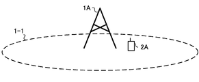
- FIG. 1 is a diagram showing an example of a communication system according to the present embodiment.
- the communication system in this embodiment includes a base station device 1A and a terminal device 2A.
- the coverage 1-1 is a range (communication area) in which the base station device 1A can be connected to the terminal device.
- the base station device 1A is also simply referred to as a base station device.
- the terminal device 2A is also simply referred to as a terminal device.
- the following uplink physical channels are used in the uplink wireless communication from the terminal device 2A to the base station device 1A.
- the uplink physical channel is used to transmit the information output from the upper layer.
- ⁇ PUCCH Physical Uplink Control Channel
- PUSCH Physical Uplink Shared Channel
- PRACH Physical Random Access Channel
- PUCCH is used to transmit uplink control information (Uplink Control Information: UCI).
- the uplink control information includes ACK (apositive acknowledgment) or NACK (a negative acknowledgment) (ACK / NACK) for downlink data (downlink transport block, downlink-shared channel: DL-SCH).
- ACK / NACK for downlink data is also referred to as HARQ-ACK and HARQ feedback.
- the uplink control information includes channel state information (Channel State Information: CSI) for the downlink. Further, the uplink control information includes a scheduling request (Scheduling Request: SR) used to request resources of an uplink shared channel (Uplink-Shared Channel: UL-SCH).
- the channel state information includes a rank index RI (Rank Indicator) that specifies a suitable spatial multiplexing number, a precoding matrix index PMI (Precoding Matrix Indicator) that specifies a suitable precoder, and a channel quality index CQI that specifies a suitable transmission rate.
- rank index RI Rank Indicator
- PMI Precoding Matrix Indicator
- CQI channel quality index
- CSI-RS Reference Signal
- resource index CRI CSI-RS Resource Indicator
- CSI-RS or SS Synchronous Signal
- RSRP Reference Signal Received Power
- the channel quality index CQI (hereinafter, CQI value) may be a suitable modulation method (for example, QPSK, 16QAM, 64QAM, 256QAM, etc.) and a coding rate in a predetermined band (details will be described later). it can.
- the CQI value can be an index (CQI Index) determined by the modulation method and the coding rate.
- the CQI value can be determined in advance by the system.
- the CRI indicates a CSI-RS resource having a suitable reception power / reception quality from a plurality of CSI-RS resources.
- the rank index and the precoding quality index can be set in advance by the system.
- the rank index and the precoding matrix index may be indexes defined by the spatial multiplexing number and precoding matrix information.
- a part or all of the CQI value, PMI value, RI value and CRI value are also collectively referred to as a CSI value.
- PUSCH is used to transmit uplink data (uplink transport block, UL-SCH).
- the PUSCH may also be used to send ACK / NACK and / or channel state information with the uplink data. Also, the PUSCH may be used to transmit only the uplink control information.
- PUSCH is also used to send RRC messages.
- the RRC message is information / signal processed in the radio resource control (Radio Resource Control: RRC) layer.
- PUSCH is also used to transmit MAC CE (Control Element).
- the MAC CE is information / signal processed (transmitted) in the medium access control (MAC: Medium Access Control) layer.
- the power headroom may be included in MAC CE and reported via PUSCH. That is, the MAC CE field may be used to indicate the power headroom level.
- PRACH is used to transmit the random access preamble.
- an uplink reference signal (ULRS) is used as an uplink physical signal.
- the uplink physical signal is not used to transmit the information output from the upper layer, but is used by the physical layer.
- the uplink reference signal includes DMRS (Demodulation Reference Signal), SRS (Sounding Reference Signal), and PT-RS (Phase-Tracking reference signal).
- DMRS is related to the transmission of PUSCH or PUCCH.
- the base station device 1A uses DMRS to perform channel correction of PUSCH or PUCCH.
- the base station device 1A uses SRS to measure the uplink channel state.
- the SRS is used for uplink observation (sounding).
- PT-RS is also used to compensate for phase noise.
- the uplink DMRS is also called an uplink DMRS.
- the following downlink physical channels are used in downlink radio communication from the base station device 1A to the terminal device 2A.
- the downlink physical channel is used to transmit information output from the upper layer.
- PBCH Physical Broadcast Channel
- PCFICH Physical Control Format Indicator Channel
- PHICH Physical Hybrid automatic repeat request Indicator Channel
- PDCCH Physical Downlink Control Channel
- EPDCCH Enhanced Physical Downlink Control Channel
- PDSCH Physical Downlink Shared Channel
- PBCH is used to notify the master information block (Master Information Block: MIB, Broadcast Channel: BCH) that is commonly used by terminal devices.
- the PCFICH is used to transmit information indicating an area used for transmitting the PDCCH (for example, the number of OFDM (Orthogonal Frequency Division Multiplexing) symbols).
- the MIB is also called minimum system information.
- PHICH is used to transmit ACK / NACK for the uplink data (transport block, codeword) received by the base station device 1A. That is, PHICH is used to transmit a HARQ indicator (HARQ feedback) indicating ACK / NACK for uplink data. ACK / NACK is also referred to as HARQ-ACK.
- the terminal device 2A notifies the upper layer of the received ACK / NACK.
- ACK / NACK is ACK indicating that the data was correctly received, NACK indicating that the data was not received correctly, and DTX indicating that there was no corresponding data.
- the terminal device 2A notifies the upper layer of ACK.
- the PDCCH and EPDCCH are used to transmit downlink control information (Downlink Control Information: DCI).
- DCI Downlink Control Information
- a plurality of DCI formats are defined for transmission of downlink control information. That is, a field for downlink control information is defined in the DCI format and mapped to information bits.
- a DCI format 1A used for scheduling one PDSCH (transmission of one downlink transport block) in one cell is defined as the DCI format for the downlink.
- the DCI format for the downlink includes downlink control information such as information about PDSCH resource allocation, information about MCS (Modulation and Coding Scheme) for PDSCH, and TPC command for PUCCH.
- the DCI format for downlink is also referred to as downlink grant (or downlink assignment).
- DCI format 0 used for scheduling one PUSCH (transmission of one uplink transport block) in one cell is defined.
- the DCI format for the uplink includes uplink control information such as information about PUSCH resource allocation, information about MCS for PUSCH, and TPC command for PUSCH.
- the DCI format for the uplink is also called an uplink grant (or an uplink assignment).
- the DCI format for the uplink can be used for requesting (CSI request) downlink channel state information (CSI; Channel State Information; also referred to as reception quality information).
- CSI downlink channel state information
- reception quality information also referred to as reception quality information
- the DCI format for the uplink can be used for setting the uplink resource that maps the channel state information report (CSI feedback report) that the terminal device feeds back to the base station device.
- the channel state information report can be used for setting indicating an uplink resource that periodically reports the channel state information (Periodic CSI).
- the channel state information report can be used for mode setting (CSI report mode) for periodically reporting channel state information.
- the channel state information report can be used for setting the uplink resource that reports irregular channel state information (Aperiodic CSI).
- the channel state information report can be used for mode setting (CSI report mode) in which channel state information is reported irregularly.
- the channel state information report can be used for setting the uplink resource that reports the semi-persistent channel state information (semi-persistent CSI).
- the channel state information report can be used for mode setting (CSI report mode) for semi-permanently reporting channel state information.
- the semi-persistent CSI report is a CSI report that is periodically issued during a period in which the signal is activated by an upper layer signal or downlink control information and then deactivated.
- the DCI format for the uplink can be used for setting indicating the type of channel state information report that the terminal device feeds back to the base station device.
- the types of channel state information reports include wideband CSI (for example, Wideband CQI) and narrowband CSI (for example, Subband CQI).
- the terminal device When the PDSCH resource is scheduled using the downlink assignment, the terminal device receives the downlink data on the scheduled PDSCH. In addition, when the PUSCH resource is scheduled using the uplink grant, the terminal device transmits the uplink data and / or the uplink control information on the scheduled PUSCH.
- the PDSCH is used to transmit downlink data (downlink transport block, DL-SCH).
- the PDSCH is also used to transmit the system information block type 1 message.
- the system information block type 1 message is cell-specific (cell-specific) information.
- the PDSCH is also used to send a system information message.
- the system information message includes a system information block X other than the system information block type 1.
- the system information message is cell-specific (cell-specific) information.
- the PDSCH is also used to send RRC messages.
- the RRC message transmitted from the base station device may be common to a plurality of terminal devices in the cell.
- the RRC message transmitted from the base station device 1A may be a dedicated message (also referred to as dedicated signaling) for a certain terminal device 2A. That is, the user device specific (user device specific) information is transmitted to a certain terminal device using a dedicated message.
- PDSCH is also used to transmit MAC CE.
- the RRC message and / or the MAC CE is also referred to as higher layer signaling.
- PDSCH can also be used to request downlink channel state information.
- PDSCH can be used for transmitting the uplink resource which maps the channel state information report (CSI feedback report) which a terminal device feeds back to a base station apparatus.
- the channel state information report can be used for setting indicating an uplink resource that periodically reports the channel state information (Periodic CSI).
- the channel state information report can be used for mode setting (CSI report mode) for periodically reporting channel state information.
- wideband CSI eg Wideband CSI
- narrowband CSI eg Subband CSI
- the wideband CSI calculates one channel state information for the system band of the cell.
- the narrowband CSI divides the system band into predetermined units, and calculates one channel state information for the division.
- a synchronization signal (Synchronization signal: SS) and a downlink reference signal (Downlink Reference Signal: DL) RS are used as downlink physical signals.
- the downlink physical signal is not used to transmit the information output from the upper layer, but is used by the physical layer.
- the synchronization signals include a primary synchronization signal (PrimarySynchronizationSignal: PSS) and a secondary synchronization signal (SecondarySynchronizationSignal: SSS).
- the synchronization signal is used by the terminal device to synchronize the downlink frequency domain and time domain.
- the synchronization signal is also used to measure the reception power, reception quality, or signal-to-interference and noise power ratio (SINR).
- SINR signal-to-interference and noise power ratio
- the received power measured with the sync signal is SS-RSRP (Synchronization Signal-Reference Reference Signal Received Power)
- the received quality measured with the sync signal is SS-RSRQ (Reference Signal Received Quality)
- SINR measured with the sync signal is SS- Also called SINR.
- SS-RSRQ is the ratio of SS-RSRP and RSSI.
- RSSI Receiveived Signal Strength Indicator
- the synchronization signal / downlink reference signal is used by the terminal device to perform channel correction of the downlink physical channel.
- the synchronization signal / downlink reference signal is used by the terminal device to calculate downlink channel state information.
- the downlink reference signal includes DMRS (Demodulation Reference Signal; demodulation reference signal), NZP CSI-RS (Non-Zero Power Channel State Information-Reference Reference Signal), and ZP CSI-RS (Zero Power Channel State Information Information Reference Signal), PT-RS, TRS (Tracking Reference Signal).
- DMRS Demodulation Reference Signal; demodulation reference signal
- NZP CSI-RS Non-Zero Power Channel State Information-Reference Reference Signal
- ZP CSI-RS Zero Power Channel State Information Information Reference Signal
- PT-RS Spin-RS
- TRS Track Reference Signal
- the downlink DMRS is also referred to as a downlink DMRS.
- CSI-RS when simply referring to CSI-RS, it includes NZP CSI-RS and / or ZP CSI-RS.
- DMRS is transmitted in the subframe and band used for transmission of PDSCH / PBCH / PDCCH / EPDCCH related to DMRS, and is used to demodulate PDSCH / PBCH / PDCCH / EPDCCH related to DMRS.
- the resource of NZP CSI-RS is set by the base station device 1A.
- the terminal device 2A performs signal measurement (channel measurement) or interference measurement using NZP CSI-RS.
- the NZP CSI-RS is also used for beam scanning for searching for a suitable beam direction, beam recovery for recovering when the received power / reception quality in the beam direction deteriorates, and the like.
- the ZP CSI-RS resource is set by the base station device 1A.
- the base station device 1A transmits ZP CSI-RS with zero output.
- the terminal device 2A measures interference in the resource corresponding to the ZP CSI-RS.
- the resource for interference measurement supported by ZP CSI-RS is also called CSI-IM (Interference Measurement) resource.
- the base station device 1A transmits (sets) the NZP CSI-RS resource setting for the NZP CSI-RS resource.
- the NZP CSI-RS resource settings include one or more NZP CSI-RS resource mappings, CSI-RS resource IDs of each NZP CSI-RS resource, and part or all of the number of antenna ports.
- the CSI-RS resource mapping is information (for example, resource element) indicating the OFDM symbol and subcarrier in the slot where the CSI-RS resource is arranged.
- the CSI-RS resource ID is used to identify the NZP CSI-RS resource.
- the base station device 1A transmits (sets) the CSI-IM resource setting.
- the CSI-IM resource settings include one or more CSI-IM resource mappings, CSI-IM resource setting IDs for each CSI-IM resource.
- the CSI-IM resource mapping is information (for example, resource element) indicating the OFDM symbol and subcarrier in the slot in which the CSI-IM resource is arranged.
- the CSI-IM resource setting ID is used to identify the CSI-IM setting resource.
- CSI-RS is used to measure received power, received quality, or SINR.
- the reception power measured by CSI-RS is also called CSI-RSRP
- the reception quality measured by CSI-RS is called CSI-RSRQ
- the SINR measured by CSI-RS is also called CSI-SINR.
- CSI-RSRQ is the ratio of CSI-RSRP and RSSI.
- CSI-RS is transmitted regularly / non-periodically / semi-permanently.
- the terminal device is set in the upper layer.
- a CSI report setting that is a CSI report setting
- a CSI resource setting that is a resource setting for measuring CSI
- a measurement link setting that links the CSI report setting and the CSI resource setting for CSI measurement.
- one or more report settings, resource settings, and measurement link settings are set.
- the CSI report setting includes a part or all of the report setting ID, the report setting type, the codebook setting, the CSI report amount and the block error rate target.
- the Report Setting ID is used to identify the CSI Report Setting.
- the report setting type indicates a periodic / aperiodic / semi-permanent CSI report.
- the CSI report amount indicates the amount (value, type) to be reported, and is, for example, part or all of CRI, RI, PMI, CQI, or RSRP.
- the block error rate target is a target of the block error rate assumed when calculating the CQI.
- the CSI resource configuration includes a resource configuration ID, a synchronization signal block resource measurement list, a resource configuration type, a part or all of one or more resource set configurations.
- the resource setting ID is used to specify the resource setting.
- the synchronization signal block resource setting list is a list of resources for which measurement using the synchronization signal is performed.
- the resource setting type indicates whether the CSI-RS is transmitted regularly, irregularly or semi-permanently. In addition, in the case where the CSI-RS is set to be transmitted semi-permanently, the CSI-RS is periodically transmitted during the period from the activation by the upper layer signal or the downlink control information to the deactivation. ..
- the CSI-RS resource set setting includes a part or all of information indicating a CSI-RS resource set setting ID, resource repetition, and one or more CSI-RS resources.
- the resource set setting ID is used to specify the CSI-RS resource set setting.
- Resource repetition indicates ON / OFF of resource repetition in the resource set. When resource repetition is ON, it means that the base station apparatus uses a fixed (same) transmission beam for each of the plurality of CSI-RS resources in the resource set. In other words, when resource repetition is ON, the terminal device assumes that the base station device uses a fixed (same) transmission beam for each of the plurality of CSI-RS resources in the resource set.
- the information indicating the CSI-RS resource includes one or more CSI-RS resource IDs and one or more CSI-IM resource setting IDs.
- the measurement link setting includes the measurement link setting ID, the report setting ID, and a part or all of the resource setting ID, and the CSI report setting and the CSI resource setting are linked.
- the measurement link setting ID is used to specify the measurement link setting.
- PT-RS is associated with DMRS (DMRS port group).
- the number of antenna ports of PT-RS is 1 or 2, and each PT-RS port (PT-RS antenna port) is associated with a DMRS port group (DMRS antenna port group).
- the terminal device assumes that the PT-RS port and the DMRS port (DMRS antenna port) are QCL with respect to delay spread, Doppler spread, Doppler shift, average delay, and spatial reception (Rx) parameter.
- the base station device sets the PT-RS setting with the signal of the upper layer. When the PT-RS setting is set, the PT-RS may be transmitted.
- the PT-RS is not transmitted in the case of a predetermined MCS (for example, when the modulation scheme is QPSK).
- time density and frequency density are set.
- the time density indicates a time interval in which the PT-RS is arranged. Time density is shown as a function of scheduled MCS. The time density also includes the absence of PT-RS (not transmitted).
- the frequency density indicates a frequency interval in which PT-RSs are arranged. Frequency density is a function of scheduled bandwidth. The frequency density also includes the absence of PT-RS (not transmitted). When the time density or the frequency density indicates that the PT-RS does not exist (is not transmitted), the PT-RS does not exist (is not transmitted).
- MBSFN Multimedia Broadcast multicast service Single Frequency Network
- the RS is transmitted in the entire band of the subframe used for transmitting the PMCH.
- MBSFN RS is used to perform demodulation of PMCH.
- PMCH is transmitted by the antenna port used for transmission of MBSFN RS.
- the downlink physical channel and the downlink physical signal are collectively referred to as a downlink signal.
- the uplink physical channel and the uplink physical signal are also collectively referred to as an uplink signal.
- the downlink physical channel and the uplink physical channel are collectively referred to as a physical channel.
- the downlink physical signal and the uplink physical signal are collectively referred to as a physical signal.
- BCH, UL-SCH and DL-SCH are transport channels.
- the channel used in the MAC layer is called a transport channel.
- the unit of the transport channel used in the MAC layer is also called a transport block (Transport Block: TB) or a MAC PDU (Protocol Data Unit).
- a transport block is a unit of data that the MAC layer passes (deliver) to the physical layer. In the physical layer, transport blocks are mapped to codewords, and an encoding process or the like is performed for each codeword.
- the base station device can integrate and communicate with multiple component carriers (CCs) for more broadband transmission.
- CCs component carriers
- PCell Primary Cell
- SCell Secondary Cell
- a master cell group MCG; Master Cell Group
- SCG Secondary Cell Group
- the MCG is composed of a PCell and optionally one or more SCells.
- the SCG is composed of a primary SCell (PSCell) and optionally one or more SCells.
- the base station device can communicate using wireless frames.
- the radio frame is composed of a plurality of subframes (subsections).
- the radio frame length can be 10 milliseconds (ms) and the subframe length can be 1 ms.
- the radio frame is composed of 10 subframes.
- a slot is composed of 14 OFDM symbols. Since the OFDM symbol length may change depending on the subcarrier spacing, the slot length may also change at the subcarrier spacing.
- a minislot is composed of fewer OFDM symbols than slots. Slots / minislots can be scheduling units. The terminal device can know the slot-based scheduling / minislot-based scheduling from the position (arrangement) of the first downlink DMRS. In slot-based scheduling, the first downlink DMRS is placed in the third or fourth symbol of the slot. In minislot-based scheduling, the first downlink DMRS is arranged in the first symbol of scheduled data (resource, PDSCH). The slot-based scheduling is also called PDSCH mapping type A. Minislot-based scheduling is also called PDSCH mapping type B.
- a resource block is defined by 12 consecutive subcarriers.
- a resource element is defined by a frequency domain index (for example, a subcarrier index) and a time domain index (for example, an OFDM symbol index).
- Resource elements are classified into uplink resource elements, downlink elements, flexible resource elements, and reserved resource elements. In the reserved resource element, the terminal device does not transmit the uplink signal and does not receive the downlink signal.
- SCS subcarrier spacing
- the SCS is 15/30/60/120/240/480 kHz.
- Base station device / terminal device can communicate in licensed band or unlicensed band.
- the base station device / terminal device can communicate with at least one SCell operating in the unlicensed band by carrier aggregation, with the license band being PCell.
- the base station device / terminal device can perform dual connectivity communication in which the master cell group communicates in the license band and the secondary cell group communicates in the unlicensed band.
- the base station device / terminal device can communicate only with PCell in the unlicensed band.
- the base station device / terminal device can communicate with CA or DC only in the unlicensed band.
- the license band is PCell and that the cells (SCell, PSCell) of the unlicensed band are assisted and communicated with, for example, CA, DC, etc.
- LAA Licensed-Assisted Access
- ULSA unlicensed standalone access
- LA license access
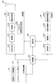
- FIG. 2 is a schematic block diagram showing the configuration of the base station device in this embodiment.
- the base station apparatus includes an upper layer processing unit (upper layer processing step) 101, a control unit (control step) 102, a transmission unit (transmission step) 103, a reception unit (reception step) 104, and a transmission / reception antenna. 105 and a measuring unit (measuring step) 106.
- the upper layer processing unit 101 is configured to include a radio resource control unit (radio resource control step) 1011 and a scheduling unit (scheduling step) 1012.
- the transmission unit 103 includes a coding unit (coding step) 1031, a modulation unit (modulation step) 1032, a downlink reference signal generation unit (downlink reference signal generation step) 1033, a multiplexing unit (multiplexing step) 1034, and a radio.
- a transmitter (wireless transmission step) 1035 is included.
- the receiving unit 104 includes a wireless receiving unit (wireless receiving step) 1041, a demultiplexing unit (demultiplexing step) 1042, a demodulating unit (demodulating step) 1043, and a decoding unit (decoding step) 1044.
- the upper layer processing unit 101 includes a medium access control (MAC) layer, a packet data integration protocol (Packet Data Convergence Protocol: PDCP) layer, a radio link control (Radio Link Control: RLC) layer, and a radio resource control (Radio). Resource Control: RRC) layer is processed. Further, upper layer processing section 101 generates information necessary for controlling transmitting section 103 and receiving section 104, and outputs it to control section 102.
- MAC medium access control
- PDCP Packet Data Convergence Protocol
- RLC Radio Link Control
- Radio Radio Resource Control
- the upper layer processing unit 101 receives information regarding the terminal device such as the function (UE capability) of the terminal device from the terminal device. In other words, the terminal device transmits its own function to the base station device as an upper layer signal.
- the information about the terminal device includes information indicating whether the terminal device supports a predetermined function, or information indicating that the terminal device has completed the introduction and the test for the predetermined function.
- whether or not a given function is supported includes whether or not the introduction and testing of the given function have been completed.
- the terminal device transmits information (parameter) indicating whether or not the predetermined function is supported.
- the terminal device does not transmit information (parameter) indicating whether or not the predetermined function is supported. That is, whether or not the predetermined function is supported is notified by whether or not information (parameter) indicating whether or not the predetermined function is supported is transmitted.
- Information (parameter) indicating whether or not a predetermined function is supported may be notified by using 1 bit of 1 or 0.
- the radio resource control unit 1011 generates downlink data (transport block), system information, RRC message, MAC CE, etc. arranged on the downlink PDSCH, or acquires from the upper node. Radio resource control section 1011 outputs downlink data to transmission section 103 and outputs other information to control section 102. Further, the wireless resource control unit 1011 manages various setting information of the terminal device.
- the scheduling unit 1012 determines frequencies and subframes to which physical channels (PDSCH and PUSCH) are assigned, coding rates and modulation schemes (or MCS) of physical channels (PDSCH and PUSCH), transmission power, and the like.
- the scheduling unit 1012 outputs the determined information to the control unit 102.
- the scheduling unit 1012 generates information used for scheduling the physical channels (PDSCH and PUSCH) based on the scheduling result.
- the scheduling unit 1012 outputs the generated information to the control unit 102.
- the control unit 102 generates a control signal for controlling the transmission unit 103 and the reception unit 104 based on the information input from the upper layer processing unit 101.
- the control unit 102 generates downlink control information based on the information input from the upper layer processing unit 101, and outputs the downlink control information to the transmission unit 103.
- the transmission unit 103 generates a downlink reference signal according to the control signal input from the control unit 102, and encodes the HARQ indicator, the downlink control information, and the downlink data input from the higher layer processing unit 101. And modulates, multiplexes PHICH, PDCCH, EPDCCH, PDSCH, and downlink reference signal, and transmits the signal to the terminal device 2A via the transmission / reception antenna 105.
- the coding unit 1031 performs block coding, convolutional coding, turbo coding, LDPC (Low Density Parity Check: Low density) on the HARQ indicator, the downlink control information, and the downlink data input from the upper layer processing unit 101.
- encoding is performed using a predetermined encoding method such as parity check) encoding or Polar encoding, or encoding is performed using the encoding method determined by the radio resource control unit 1011.
- the modulation unit 1032 determines the coded bits input from the coding unit 1031 in advance by BPSK (Binary Phase Shift Keying), QPSK (quadrature Phase Shift Keying), 16QAM (quadrature amplitude modulation), 64QAM, 256QAM, etc. Alternatively, it is modulated by the modulation method determined by the radio resource control unit 1011.
- the downlink reference signal generation unit 1033 refers to a sequence known to the terminal device 2A based on a predetermined rule based on a physical cell identifier (PCI, cell ID) for identifying the base station device 1A Generate as a signal.
- PCI physical cell identifier
- the multiplexing unit 1034 multiplexes the modulated modulation symbol of each channel, the generated downlink reference signal, and the downlink control information. That is, multiplexing section 1034 arranges the modulated symbols of each modulated channel, the generated downlink reference signal, and downlink control information in resource elements.
- the wireless transmission unit 1035 generates an OFDM symbol by performing an inverse fast Fourier transform (IFFT) on the multiplexed modulation symbols and the like, adds a cyclic prefix (cyclic prefix: CP) to the OFDM symbol, and bases the OFDM symbol on the base.
- IFFT inverse fast Fourier transform
- CP cyclic prefix
- the reception unit 104 separates, demodulates, and decodes the reception signal received from the terminal device 2A via the transmission / reception antenna 105 according to the control signal input from the control unit 102, and outputs the decoded information to the upper layer processing unit 101. ..
- the wireless reception unit 1041 down-converts an uplink signal received via the transmission / reception antenna 105 into a baseband signal, removes unnecessary frequency components, and amplifies so that the signal level is appropriately maintained.
- the level is controlled, quadrature demodulation is performed based on the in-phase component and the quadrature component of the received signal, and the quadrature-demodulated analog signal is converted into a digital signal.
- the wireless reception unit 1041 removes a portion corresponding to CP from the converted digital signal.
- the wireless reception unit 1041 performs a fast Fourier transform (FFT) on the signal from which the CP is removed, extracts a frequency domain signal, and outputs the signal to the demultiplexing unit 1042.
- FFT fast Fourier transform
- the demultiplexing unit 1042 separates the signal input from the wireless reception unit 1041 into signals such as PUCCH, PUSCH, and uplink reference signal. Note that this separation is performed based on the radio resource allocation information included in the uplink grant, which the base station device 1A has previously determined by the radio resource control unit 1011 and has notified each terminal device 2A.
- the demultiplexing unit 1042 compensates the propagation paths of PUCCH and PUSCH. Also, the demultiplexing unit 1042 separates the uplink reference signal.
- the demodulation unit 1043 performs an inverse discrete Fourier transform (Inverse Discrete Fourier Transform: IDFT) on the PUSCH, acquires a modulation symbol, and for each of the PUCCH and PUSCH modulation symbols, BPSK, QPSK, 16QAM, 64QAM, 256QAM, and the like in advance.
- IDFT Inverse Discrete Fourier Transform
- the received signal is demodulated by using a modulation method which is set or which is notified to the terminal device 2A in advance by the uplink device.
- the decoding unit 1044 uses the coding rate of the demodulated PUCCH and PUSCH with a predetermined coding method, a predetermined coding method, or a coding rate that the self apparatus notifies the terminal apparatus 2A in advance by an uplink grant. Decoding is performed, and the decoded uplink data and uplink control information are output to upper layer processing section 101. When PUSCH is retransmitted, decoding section 1044 performs decoding using the coded bits held in HARQ buffer input from upper layer processing section 101 and the demodulated coded bits.
- the measurement unit 106 observes the received signal and obtains various measured values such as RSRP / RSRQ / RSSI.
- the measurement unit 106 also obtains received power, reception quality, and a suitable SRS resource index from the SRS transmitted from the terminal device.
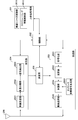
- FIG. 3 is a schematic block diagram showing the configuration of the terminal device in this embodiment.
- the terminal device includes an upper layer processing unit (upper layer processing step) 201, a control unit (control step) 202, a transmission unit (transmission step) 203, a reception unit (reception step) 204, and a measurement unit ( The measurement step) 205 and the transmission / reception antenna 206 are included.
- the upper layer processing unit 201 is configured to include a radio resource control unit (radio resource control step) 2011 and a scheduling information interpretation unit (scheduling information interpretation step) 2012.
- the transmission unit 203 includes a coding unit (coding step) 2031, a modulation unit (modulation step) 2032, an uplink reference signal generation unit (uplink reference signal generation step) 2033, a multiplexing unit (multiplexing step) 2034, and a radio.
- the transmission unit (wireless transmission step) 2035 is included.
- the receiving unit 204 includes a wireless receiving unit (wireless receiving step) 2041, a demultiplexing unit (demultiplexing step) 2042, and a signal detecting unit (signal detecting step) 2043.
- the upper layer processing unit 201 outputs the uplink data (transport block) generated by a user operation or the like to the transmission unit 203.
- the upper layer processing unit 201 is a medium access control (Medium Access Control: MAC) layer, a packet data integration protocol (Packet Data Convergence Protocol: PDCP) layer, a radio link control (Radio Link Control: RLC) layer, a radio resource control. (Radio Resource Control: RRC) Layer processing is performed.
- Medium Access Control: MAC Medium Access Control
- PDCP Packet Data Convergence Protocol
- RLC Radio Link Control
- RRC Radio Resource Control
- the upper layer processing unit 201 outputs information indicating the function of the terminal device supported by the own terminal device to the transmitting unit 203.
- the wireless resource control unit 2011 manages various setting information of its own terminal device. In addition, the radio resource control unit 2011 generates information arranged in each uplink channel and outputs the information to the transmission unit 203.
- the wireless resource control unit 2011 acquires the setting information transmitted from the base station device and outputs it to the control unit 202.
- the scheduling information interpretation unit 2012 interprets the downlink control information received via the reception unit 204 and determines the scheduling information.
- the scheduling information interpretation unit 2012 also generates control information for controlling the reception unit 204 and the transmission unit 203 based on the scheduling information, and outputs the control information to the control unit 202.
- the control unit 202 generates a control signal for controlling the receiving unit 204, the measuring unit 205, and the transmitting unit 203 based on the information input from the upper layer processing unit 201.
- the control unit 202 outputs the generated control signal to the receiving unit 204, the measuring unit 205, and the transmitting unit 203 to control the receiving unit 204 and the transmitting unit 203.
- the control unit 202 controls the transmission unit 203 to transmit the CSI / RSRP / RSRQ / RSSI generated by the measurement unit 205 to the base station device.
- the reception unit 204 separates, demodulates, and decodes the reception signal received from the base station device via the transmission / reception antenna 206 according to the control signal input from the control unit 202, and outputs the decoded information to the upper layer processing unit 201. To do.
- the wireless reception unit 2041 converts a downlink signal received via the transmission / reception antenna 206 into a baseband signal by down conversion, removes unnecessary frequency components, and an amplification level so that the signal level is appropriately maintained. Quadrature demodulation based on the in-phase component and the quadrature component of the received signal, and the quadrature-demodulated analog signal is converted into a digital signal.
- the wireless reception unit 2041 removes a portion corresponding to the CP from the converted digital signal, performs a fast Fourier transform on the signal from which the CP is removed, and extracts a signal in the frequency domain.
- Demultiplexing section 2042 separates the extracted signal into PHICH, PDCCH, EPDCCH, PDSCH, and downlink reference signal, respectively. Further, demultiplexing section 2042 performs channel compensation for PHICH, PDCCH, and EPDCCH based on the channel estimation value of the desired signal obtained from the channel measurement, detects downlink control information, and causes control section 202 to perform control. Output. Further, the control unit 202 outputs the PDSCH and the channel estimation value of the desired signal to the signal detection unit 2043.
- the signal detection unit 2043 demodulates and decodes using the PDSCH and the channel estimation value, and outputs it to the upper layer processing unit 201. Further, when removing or suppressing the interference signal, the signal detection unit 2043 obtains the channel estimation value of the interference channel using the parameter of the interference signal, and demodulates and decodes the PDSCH.
- the measurement unit 205 performs various measurements such as CSI measurement, RRM (Radio Resource Management) measurement, and RLM (Radio Link Monitoring) measurement, and obtains CSI / RSRP / RSRQ / RSSI.
- CSI measurement CSI measurement
- RRM Radio Resource Management
- RLM Radio Link Monitoring
- the transmission unit 203 generates an uplink reference signal according to the control signal input from the control unit 202, encodes and modulates the uplink data (transport block) input from the higher layer processing unit 201, and PUCCH,
- the PUSCH and the generated uplink reference signal are multiplexed and transmitted to the base station apparatus via the transmission / reception antenna 206.
- the coding unit 2031 performs coding such as convolutional coding, block coding, turbo coding, LDPC coding, and Polar coding on the uplink control information or the uplink data input from the upper layer processing unit 201.
- the modulation unit 2032 modulates the coded bits input from the coding unit 2031 by the modulation method notified by the downlink control information such as BPSK, QPSK, 16QAM, 64QAM, or a predetermined modulation method for each channel. ..
- the uplink reference signal generation unit 2033 uses a physical cell identifier (referred to as physical cell identity: PCI, Cell ID, etc.) for identifying the base station device, a bandwidth in which the uplink reference signal is arranged, and an uplink grant.
- a sequence obtained by a predetermined rule (expression) is generated based on the notified cyclic shift, the value of the parameter for generating the DMRS sequence, and the like.
- the multiplexing unit 2034 multiplexes the PUCCH and PUSCH signals and the generated uplink reference signal for each transmission antenna port. That is, multiplexing section 2034 arranges the PUCCH and PUSCH signals and the generated uplink reference signal in resource elements for each transmission antenna port.
- the wireless transmission unit 2035 performs an inverse fast Fourier transform (Inverse Fast Fourier Transform: IFFT) on the multiplexed signal, performs OFDM modulation, generates an OFDMA symbol, and adds a CP to the generated OFDMA symbol, Generates a baseband digital signal, converts the baseband digital signal to an analog signal, removes excess frequency components, converts to a carrier frequency by up-conversion, power-amplifies, outputs to the transmission / reception antenna 206, and transmits. To do.
- IFFT inverse Fast Fourier transform
- the terminal device can perform not only the OFDMA method but also the SC-FDMA method.
- FIG. 4 shows an example of a communication system according to this embodiment.
- the communication system shown in FIG. 4 includes a base station device 3A and terminal devices 4A and 4B.
- the terminal devices 4A and 4B are also simply referred to as terminal devices.
- ultra-high-capacity communication such as ultra-high-definition video transmission
- ultra-wide band transmission utilizing high frequency band is desired.
- For transmission in the high frequency band it is necessary to compensate for path loss, and beamforming is important.
- an ultra-dense network (Ultra-dense network) in which base station devices are densely arranged is used. network) is valid.
- the base station devices are arranged at a high density, although the SNR (Signal to noise power ratio) is greatly improved, there is a possibility that strong interference may occur due to beamforming. Therefore, interference control (avoidance, suppression, removal) in consideration of beamforming and / or cooperative communication of a plurality of base stations is required to realize ultra-high-capacity communication for all terminal devices in the limited area. Will be needed.
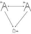
- FIG. 5 shows an example of a downlink communication system according to this embodiment.
- the communication system shown in FIG. 5 includes a base station device 3A, a base station device 5A, and a terminal device 4A.
- the terminal device 4A can use the base station device 3A and / or the base station device 5A as a serving cell.
- the base station device 3A or the base station device 5A is provided with a large number of antennas, a large number of antennas are provided in a plurality of subarrays (panel, subpanel, transmission antenna port, transmission antenna group, reception antenna port, reception antenna group, antenna group). , Antenna port group), and transmit / receive beamforming can be applied to each subarray.
- each sub array can include a communication device, and the configuration of the communication device is the same as the configuration of the base station device shown in FIG. 2 unless otherwise specified.
- the terminal device 4A can perform transmission or reception by beamforming.
- the terminal device 4A includes a large number of antennas, a large number of antennas are arranged in a plurality of subarrays (panel, subpanel, transmission antenna port, transmission antenna group, reception antenna port, reception antenna group, antenna group, antenna port group).
- different transmit / receive beamforming can be applied to each subarray.
- Each sub-array can include a communication device, and the configuration of the communication device is the same as that of the terminal device shown in FIG. 3 unless otherwise specified.
- the base station device 3A and the base station device 5A are also simply referred to as base station devices.
- the terminal device 4A is also simply referred to as a terminal device.
- a synchronization signal is used to determine a suitable transmission beam for the base station device and a suitable reception beam for the terminal device.
- the base station device transmits a synchronization signal block composed of PSS, PBCH, and SSS.
- a synchronization signal block burst set period set by the base station apparatus one or more synchronization signal blocks are transmitted in the time domain, and a time index is set for each synchronization signal block.
- the sync signal block having the same time index within the sync signal block burst set period has delay spread, Doppler spread, Doppler shift, average gain, average delay, spatial reception parameter, and / or spatial transmission parameter.
- the spatial reception parameters are, for example, spatial correlation of channels, angle of arrival (angle of arrival), reception beam direction, and the like.
- the spatial transmission parameters are, for example, channel spatial correlation, transmission angle (Angle Departure), transmission beam direction, and the like. That is, the terminal device can assume that within the synchronization signal block burst set period, synchronization signal blocks with the same time index are transmitted with the same transmission beam, and synchronization signal blocks with different time indexes are transmitted with different beams.
- the base station device can know the transmission beam suitable for the terminal device. Also, the terminal device can obtain a reception beam suitable for the terminal device by using the synchronization signal blocks having the same time index in different synchronization signal block burst set periods. Therefore, the terminal device can associate the time index of the synchronization signal block with the reception beam direction and / or the sub-array. When the terminal device includes a plurality of sub-arrays, different sub-arrays may be used when connecting to different cells.
- the time index of the synchronization signal block is also referred to as SSB index or SSB resource indicator (SSBRI).
- QCL types there are four QCL types that indicate the QCL status.
- the four QCL types are called QCL type A, QCL type B, QCL type C, and QCL type D, respectively.
- QCL type A is a relationship (state) in which Doppler shift, Doppler spread, average delay, and delay spread become QCL.
- QCL type B is a relationship (state) in which Doppler shift and Doppler spread are QCL.
- QCL type C is a relationship (state) in which the average delay and Doppler shift are QCL.
- the QCL type D is a relationship (state) in which the spatial reception parameter is QCL.
- the above four QCL types can be combined with each other. For example, QCL type A + QCL type D, QCL type B + QCL type D, and the like.
- one or more TCI (Transmit Configuration Indicator) states are set by the signal of the upper layer.
- One TCI state can set the QCL type with one or a plurality of downlink signals in a cell (cell ID) and a partial band (BWP-ID).
- the downlink signal includes CSI-RS and SSB.
- the TCI state is set by the RRC message (signaling), and one or more of the set TCI states are activated / deactivated in the MAC layer.
- the TCI state can associate the QCL of the downlink signal with the DMRS of the PDSCH. For example, one or more of the TCI states activated by DCI are indicated and can be used for demodulation (decoding) of the associated PDSCH.
- the terminal device can know the reception beam direction (spatial reception filter) of the associated PDSCH. Therefore, the TCI can be said to be information related to the reception beam direction of the terminal device. Also, the TCI state can associate the QCL of the downlink signal with the DMRS of the PDCCH. From the one or more TCI states set by the RRC message (signaling), one TCI state is activated in the MAC layer as the TCI state for the PDCCH. This allows the terminal device to know the reception beam direction of PDCCH DMRS. The receive beam direction of the default PDCCH DMRS is associated with the SSB index at the time of initial access.
- CSI-RS can be used to determine a suitable transmission beam of the base station device and a suitable reception beam of the terminal device.
- the terminal device receives the CSI-RS with the resource set in the CSI resource setting, calculates the CSI or RSRP from the CSI-RS, and reports it to the base station device. Further, when the CSI-RS resource setting includes a plurality of CSI-RS resource settings and / or when resource repetition is OFF, the terminal device receives the CSI-RS with the same reception beam on each CSI-RS resource, Calculate CRI. For example, when the CSI-RS resource set configuration includes K (K is an integer of 2 or more) CSI-RS resource configurations, the CRI indicates N CSI-RS resources suitable from the K CSI-RS resources. .. However, N is a positive integer less than K.
- the terminal device may report the CSI-RSRP measured by each CSI-RS resource to the base station device in order to indicate which CSI-RS resource has good quality. it can. If the base station apparatus performs beamforming (precoding) of CSI-RSs in different beam directions with a plurality of set CSI-RS resources and transmits the CSI-RSs, the base station apparatus suitable for the terminal apparatus according to the CRI reported from the terminal apparatus. It is possible to know the transmission beam direction of. On the other hand, the preferred receiving beam direction of the terminal device can be determined using the CSI-RS resource to which the transmitting beam of the base station device is fixed.
- the terminal device receives the CSI-RS resources received in different reception beam directions in each CSI-RS resource.
- a suitable reception beam direction can be obtained from RS.
- the terminal device may report CSI-RSRP after determining a suitable reception beam direction.
- the terminal device can select a suitable sub-array when obtaining a suitable reception beam direction.
- the preferred reception beam direction of the terminal device may be associated with the CRI (or CSI-RS resource ID).
- the base station device can fix the transmission beam with the CSI-RS resource associated with each CRI (or CSI-RS resource ID).
- the terminal device can determine a suitable reception beam direction for each CRI (or CSI-RS resource ID).
- the base station apparatus can associate downlink signals / channels with CRIs (or CSI-RS resource IDs) and transmit them.
- the terminal device must receive with the receive beam associated with the CRI.
- different base station apparatuses can transmit CSI-RS in the set plurality of CSI-RS resources. In this case, the network side can know from which base station device the communication quality is good by the CRI (or CSI-RS resource ID).
- the terminal device when the terminal device includes a plurality of sub-arrays, the sub-arrays can be received at the same timing. Therefore, if the base station apparatus associates and transmits a CRI (or CSI-RS resource ID) to each of a plurality of layers (codewords, transport blocks) in downlink control information or the like, the terminal apparatus can transmit each CRI (or CSI). -Multiple layers can be received by using a sub-array corresponding to (RS resource ID) and a reception beam. However, when using an analog beam, when one receive beam direction is used in one sub array at the same timing, two CRIs (or CSI-RS resource IDs) corresponding to one sub array of the terminal device are simultaneously set.
- the terminal device may not be able to receive with multiple receive beams.
- the base station device divides a plurality of set CSI-RS resources into groups, and within the group, the CRI is obtained using the same subarray. Also, if different subarrays are used between groups, the base station device can know a plurality of CRIs that can be set at the same timing.
- the group of CSI-RS resources may be CSI-RS resources set by CSI resource setting or CSI-RS resource set setting.
- the CRI (or CSI-RS resource ID) that can be set at the same timing may be QCL. At this time, the terminal device can transmit the CRI (or CSI-RS resource ID) in association with the QCL information.
- the QCL information is information on the QCL for a given antenna port, a given signal, or a given channel.
- the long-term characteristics of the channel carrying the symbols on one antenna port can be inferred from the channel carrying the symbols on the other antenna port, then those antenna ports are QCL. Is called.
- the long-term characteristic includes delay spread, Doppler spread, Doppler shift, average gain, average delay, spatial reception parameter, and / or spatial transmission parameter. For example, when the two antenna ports are QCL, the terminal device can consider that the long-term characteristics at those antenna ports are the same.
- the base station device has the same CRI that is QCL regarding spatial reception parameters. It is possible to set the CRI that is not QCL with respect to the spatial reception parameter to the same timing without setting the timing.
- the base station apparatus may request CSI for each sub-array of the terminal apparatus. In this case, the terminal device reports the CSI for each sub array.
- the terminal device reports a plurality of CRIs to the base station device, it may report only the CRIs that are not QCL.
- a codebook in which predetermined precoding (beamforming) matrix (vector) candidates are specified is used.
- the base station apparatus transmits CSI-RS, the terminal apparatus obtains a suitable precoding (beamforming) matrix from the codebook, and reports it to the base station apparatus as PMI.
- the base station device can know the transmission beam direction suitable for the terminal device.
- the codebook includes a precoding (beamforming) matrix for synthesizing antenna ports and a precoding (beamforming) matrix for selecting antenna ports.
- the base station apparatus can use different transmission beam directions for each antenna port.
- the base station device can know a suitable transmission beam direction.
- the preferred reception beam of the terminal device may be the reception beam direction associated with the CRI (or CSI-RS resource ID), or the suitable reception beam direction may be determined again.
- a preferred reception beam direction of a terminal device is a reception beam direction associated with a CRI (or CSI-RS resource ID)
- a reception beam direction for receiving CSI-RS Is preferably received in the receive beam direction associated with the CRI (or CSI-RS resource ID). Note that the terminal device can associate the PMI and the receive beam direction even when using the receive beam direction associated with the CRI (or CSI-RS resource ID).
- each antenna port may be transmitted from a different base station apparatus (cell).
- the base station device can know with which base station device (cell) the communication quality is suitable.
- the antenna ports of different base station devices (cells) may not be QCL.
- Collaborative communication between a plurality of base station devices (transmission / reception points) includes, for example, DPS (Dynamic Point Selection; dynamic point selection) that dynamically switches suitable base station devices (transmission / reception points), and a plurality of base station devices (transmission / reception points).
- DPS Dynamic Point Selection
- dynamic point selection dynamically switches suitable base station devices
- transmission / reception points a plurality of base station devices (transmission / reception points).
- From JT Joint Transmission
- Reliability can be improved by transmitting the same data from multiple base station devices (transmission / reception points), and frequency utilization efficiency and throughput can be improved by transmitting different data from multiple base station devices (transmission / reception points). Can be made.
- the terminal device may communicate using a plurality of subarrays.
- the terminal device 4A can use the sub array 1 when communicating with the base station device 3A, and can use the sub array 2 when communicating with the base station device 5A.
- the terminal device performs cooperative communication with a plurality of base station devices, there is a possibility that the plurality of subarrays will be dynamically switched or that the plurality of subarrays will transmit and receive at the same timing. At this time, it is desirable that the terminal device 4A and the base station device 3A / 5A share information regarding the sub-array of the terminal device used for communication.
- the terminal device can include CSI setting information in the CSI report.
- the CSI setting information can include information indicating a sub array.
- the terminal device can transmit a CSI report including a CRI (or CSI-RS resource ID) and an index indicating a subarray.
- the base station apparatus can associate the transmission beam direction with the subarray of the terminal apparatus.
- the terminal device can transmit a CRI report including a plurality of CRIs (or CSI-RS resource IDs).
- the station device can associate the index indicating the sub-array and the CRI (or CSI-RS resource ID).
- the terminal apparatus can jointly code the CRI (or CSI-RS resource ID) and the index indicating the subarray to transmit the CRI report in order to reduce the control information.
- N is an integer of 2 or more bits indicating the CRI
- 1 bit indicates the sub array 1 or 2
- the remaining bits indicate the CRI.
- the CSI setting information can also include CSI measurement setting information.
- the setting information for CSI measurement may be the measurement link setting or other setting information. This allows the terminal device to associate the CSI measurement setting information with the sub-array and / or receive beam direction.
- the setting of the CSI-RS for channel measurement transmitted by the base station device 3A is set as resource setting 1
- the setting of the CSI-RS for channel measurement transmitted by the base station device 5A is set as resource setting 2.
- the setting information 1 can be the resource setting 1
- the setting information 2 can be the resource setting 2
- the setting information 3 can be the resource setting 1 and the resource setting 2.
- each setting information may include the setting of the interference measurement resource. If the CSI measurement is performed based on the setting information 1, the terminal device can measure the CSI with the CSI-RS transmitted from the base station device 3A. If the CSI measurement is performed based on the setting information 2, the terminal device can measure the CSI transmitted from the base station device 5A. If the CSI measurement is performed based on the setting information 3, the terminal device can measure the CSI with the CSI-RS transmitted from the base station device 3A and the base station device 5A. The terminal device can associate each of the setting information 1 to 3 with the sub-array and / or the reception beam direction used for the CSI measurement.
- the base station apparatus can instruct the preferred sub-array and / or the receiving beam direction used by the terminal apparatus by instructing the setting information 1 to 3.
- the terminal device obtains the CSI for the resource setting 1 and / or the CSI for the resource setting 2.
- the terminal device can associate the sub-array and / or the reception beam direction with each of the resource setting 1 and / or the resource setting 2.
- resource setting 1 and / or resource setting 2 can be associated with a codeword (transport block).
- the CSI for resource setting 1 can be the CSI for codeword 1 (transport block 1)
- the CSI for resource setting 2 can be the CSI for codeword 2 (transport block 2).
- the terminal device can also obtain one CSI in consideration of the resource setting 1 and the resource setting 2.
- the terminal device can associate the sub-array and / or the reception beam direction with respect to each of the resource setting 1 and the resource setting 2 even when obtaining one CSI.
- the CSI setting information includes, when a plurality of resource settings are set (for example, when the above setting information 3 is set), the CSI includes one CRI or a CRI for each of the plurality of resource settings. Information indicating whether to include may be included.
- the CSI setting information may include a resource setting ID for which the CRI is calculated. From the CSI setting information, the base station apparatus can know under what assumption the terminal apparatus calculated the CSI or which resource setting the reception quality was good.
- the base station device can send a CSI request requesting a CSI report to the terminal device.
- the CSI request may include reporting CSI in one subarray or reporting CSI in multiple subarrays.
- the terminal device transmits a CSI report that does not include an index indicating the sub array.
- the terminal device transmits a CSI report including an index indicating the subarray.
- the base station apparatus can instruct the subarray in which the terminal apparatus calculates CSI by the index indicating the subarray or the resource setting ID. In this case, the terminal device calculates CSI with the subarray instructed by the base station device.
- the base station device can include the CSI measurement setting information in the CSI request for transmission.
- the terminal device obtains the CSI based on the CSI measurement setting information.
- the terminal device reports the CSI to the base station device, but may not report the CSI measurement setting information.
- the terminal device and the base station device can newly set a virtual antenna port in order to select a suitable subarray.
- the virtual antenna ports are each associated with a physical subarray and / or receive beam.
- the base station device can notify the terminal device of the virtual antenna port, and the terminal device can select a subarray for receiving the PDSCH.
- QCL can be set for the virtual antenna port.
- the base station device can notify the plurality of terminal devices of the virtual antenna port. When the notified virtual antenna port is QCL, the terminal device can receive the associated PDSCH using one sub-array, and the notified virtual antenna port is QCL. If not, two or more sub-arrays can be used to receive the associated PDSCH.
- the virtual antenna port can be associated with any one or a plurality of CSI-RS resources, DMRS resources, and SRS resources.
- the base station device provides a sub-array when the terminal device sends an RS in any one or more of the CSI-RS resource, DMRS resource, and SRS resource. Can be set.
- the terminal device When a plurality of base station devices perform coordinated communication, it is desirable that the terminal device receives in a sub-array and / or receive beam direction suitable for the PDSCH transmitted by each base station device. Therefore, the base station device transmits information that enables the terminal device to receive in a suitable sub-array and / or receive beam direction.
- the base station device can include the CSI setting information or the information indicating the CSI setting information in the downlink control information for transmission.
- the terminal device Upon receiving the CSI setting information, the terminal device can receive the CSI setting information in the sub-array and / or the receiving beam direction associated with the CSI setting information.
- the base station device can transmit information indicating the sub-array and / or the reception beam direction as the CSI setting information.
- the CSI setting information may be transmitted in a predetermined DCI format.
- the information indicating the reception beam direction may be the CRI (or CSI-RS resource ID), PMI, and time index of the synchronization signal block.
- the terminal device can know a suitable sub-array and / or a reception beam direction from the received DCI.
- the information indicating the sub array is represented by 1 bit or 2 bits. When the information indicating the sub array is indicated by 1 bit, the base station apparatus can indicate the sub array 1 or the sub array 2 to the terminal apparatus by "0" or "1".
- the base station apparatus can switch the sub-array and instruct the terminal apparatus to receive the sub-array. If it is decided to calculate CSI in different subarrays with different resource settings, the base station apparatus can indicate the subarray of the terminal apparatus by transmitting the DCI including the resource setting ID.
- the base station device can transmit CSI measurement setting information as CSI setting information.
- the terminal device can receive the PDSCH in the sub-array and / or the receiving beam direction associated with the CSI fed back in the setting information of the received CSI measurement.
- the CSI measurement setting information indicates the setting information 1 or the setting information 2
- the CSI setting information indicates that PDSCH transmission is associated with one resource setting information.
- the setting information of the CSI measurement indicates the setting information 3
- the CSI setting information indicates that the PDSCH transmission is related to a plurality of resource setting information.
- the CSI setting information may be associated with a parameter (field) included in DCI such as a scrambling identity (SCID) of DMRS.
- the base station apparatus can set the association between the SCID and the setting information of the CSI measurement.
- the terminal device can refer to the CSI measurement setting information from the SCID included in the DCI, and receive the PDSCH in the sub-array and / or the receiving beam direction associated with the CSI measurement setting information.
- the base station device can set two DMRS antenna port groups. These two DMRS port groups are also referred to as DMRS port group 1 (first DMRS port group) and DMRS port group 2 (second DMRS port group).
- the antenna ports in the DMRS antenna port group are QCL, and the antenna ports between the DMRS antenna port groups are not QCL. Therefore, if the DMRS antenna port group and the subarray of the terminal device are associated with each other, the base station device can instruct the subarray of the terminal device by the DMRS antenna port number included in the DCI. For example, when the DMRS antenna port number included in DCI is included in one DMRS antenna port group, the terminal device receives in one subarray corresponding to the DMRS antenna port group.
- the terminal device When the DMRS antenna port number included in the DCI is included in both of the two DMRS antenna port groups, the terminal device receives the terminal device in two subarrays.
- One DMRS antenna port group may be associated with one codeword (transport block).
- the relationship between the DMRS antenna port group and the codeword (transport block) index may be predetermined or may be instructed by the base station apparatus.
- the terminal device can specify the resource setting ID or the CSI-RS resource, and can know the sub-array and / or the reception beam direction.
- the base station device can set the DMRS antenna port group and the CSI setting information in association with each other.
- the CSI setting information includes the setting information for the CSI measurement and the setting information for the CSI measurement indicates the setting information 3
- the terminal device corresponds to the resource setting 1 in the case of the DMRS antenna port included in the DMRS antenna port group 1.
- the demodulation is performed in the sub array and / or the reception beam direction, and in the case of the DMRS antenna port included in the DMRS antenna port group 2, the demodulation is performed in the sub array and / or the reception beam direction corresponding to the resource setting 2.
- the terminal device when the report amount is set to CRI / RSRP or SSBRI / RSRP in the CSI report setting and the group-based beam reporting is set to OFF, the terminal device is different in one report, 1, 2 or Report 4 different CRIs or SSBRIs.
- the terminal device when the report amount is set to CRI / RSRP or SSBRI / RSRP in the CSI report setting and the group-based beam reporting is set to ON, the terminal device may report two different CRIs or one in one report. Report SSBRI.
- two CSI-RS resources or two SSBs can be received simultaneously by one spatial domain reception filter or a plurality of spatial domain reception filters.
- the terminal device receives the reception filter (panel, sub array) in one spatial region.
- the two CSI-RS resources are referred to as a first CSI-RS resource and a second CSI-RS resource, respectively.
- the CRI indicating the first CSI-RS resource is also referred to as a first CRI
- the CRI indicating the second CSI-RS resource is also referred to as a second CRI.
- the RI obtained by the first CSI-RS resource is also called a first RI
- the RI obtained by the second CSI-RS resource is also called a second RI.
- the CSI reported by the terminal device may change depending on whether the sum of the first RI and the second RI is 4 or less or greater than 4.
- the CQI obtained by considering both the first CSI-RS and the second CSI-RS is obtained.
- the terminal device obtains the CSI in consideration of the first CRI, the second CRI, the first RI, the second RI, and both the first CSI-RS and the second CSI-RS. Report the CQI.
- the terminal device reports the first CRI, the second CRI, the first RI, the second RI, the first CQI, and the second CQI as the CSI.
- the terminal device may receive a reception filter or a plurality of reception filters in one spatial region.
- CSI is obtained based on the two CSI-RS resources that can be received simultaneously by the spatial-domain reception filter.
- the PMI for the first CSI-RS resource is also referred to as a first PMI
- the PMI for the second CSI-RS resource is also referred to as a second PMI.
- the first PMI and the second PMI may be obtained in consideration of both the first CRI and the second CRI. In this case, the first PMI and the second PMI in which mutual interference is taken into consideration are obtained.
- PMI is divided into PMI-1 and PMI-2 when CSI-RS has four or more antenna ports.
- PMI-1 is wideband information and indicates a codebook index obtained based on at least N1 and N2.
- the number of CSI-RS antenna ports is represented by 2N1N2.
- N1 and N2 are both integers of 1 or more
- N1 represents the number of antenna ports in the first dimension (eg, horizontal direction)
- N2 represents the number of antenna ports in the second dimension (eg, vertical direction).
- the number of polarization antennas is two.
- PMI-1 includes one or more pieces of information depending on the values of N1 and N2 and RI (number of layers).
- PMI-2 is wideband or subband information and indicates at least phase rotation.
- the PMI-1 and PMI-2 obtained by the first CSI-RS resource are also referred to as the first PMI-1 and the first PMI-2, respectively.
- PMI-1 and PMI-2 obtained by the second CSI-RS resource are also referred to as a second PMI-1 and a second PMI-2, respectively.
- the report amount may be set to CRI, RI, PMI-1, and CQI. Note that CRI, RI, and CQI are the same as when the report amount is set to CRI, RI, and CQI. Therefore, when the total of the first RI and the second RI is 4 or less, the terminal device determines, as the CSI, the first CRI, the second CRI, the first RI, the second RI, and the first PMI.
- the CQI obtained by considering (PMI-1), the second PMI (PMI-1), and both the first CSI-RS and the second CSI-RS is reported.
- the terminal device determines that the CSI is the first CRI, the second CRI, the first RI, the second RI, the first PMI. (PMI-1), second PMI (PMI-1), first CQI, and second CQI are reported.
- the first RI and the second RI are equal to the second RI. Same or smaller. That is, when the RI is reported, it is preferable that the first CRI and the second CRI have better reception power (RSRP) / reception quality (RSRQ) than the first CRI, and the first CRI or The second CRI is determined.
- RSRP reception power
- RSSQ reception quality
- the terminal device may report the CSI of either the first CRI or the second CRI, for example, the one with the larger RI value. . Note that, because of the above rule, the terminal device may report the total value of the first RI and the second RI without separately reporting the first RI and the second RI.
- the base station apparatus may instruct the terminal apparatus.
- the difference may be 1 when the number of layers of codeword 1 is different from the number of layers of codeword 2.
- the first RI is 2 and the second RI is 2.
- the sum of the first RI and the second RI is 3
- the first RI is 1 and the second RI is 2.
- the sum of the first RI and the second RI is 2
- the first RI is 1 and the second RI is 1.
- the CRI with the larger RI is set higher. That is, in this embodiment, the second CRI has a higher priority than the second CRI.
- the CQI is reported by either one of the CRIs, the CQI obtained by the one CRI is reported even if the total of the first RI and the second RI is 4 or less.
- CSI When CSI is reported on PUSCH or subband CSI is reported on PUCCH, CSI is divided into two parts and reported.
- the two parts are also referred to as a first part (part 1, CSI part 1) and a second part (part 2, CSI part 2).
- the first part has a higher priority in CSI reporting than the second part.
- the first part is the sum of the first RI and the second RI (or the second RI), the second CRI, the CQI based on the first CRI and the second CRI. (Or a second CQI) is partially or entirely included.
- the second part includes a part or all of the first CRI, the first RI, the first CQI, the first PMI, and the second PMI.
- the first part includes the sum of the first RI and the second RI (or the second RI), the second CRI, or some or all of the second CQI.
- the second part includes a part or all of the first CRI, the first RI, the first CQI, the first PMI, and the second PMI.
- the CSI may be divided into three.
- the third part is also called the third part (part 3, CSI part 3).
- the third part has lower priority than the second part.
- the first part is the sum of the first RI and the second RI (or the second RI), the second CRI, the CQI based on the first CRI and the second CRI (or the second CQI). ) Part or all.
- the second part includes a part or all of the first CRI, the first RI, and the first CQI.
- the third part includes a part or all of the first PMI and the second PMI.
- the terminal device may report by dividing into two parts for each of the CSI based on the first CRI and the CSI based on the second CRI.
- the two parts of the CSI based on the first CRI are also called the first part 1 and the first part 2.
- the two parts of the CSI based on the second CRI are also called the second part 1 and the second part 2.
- the first part 1 includes a part or all of the first CRI, the first RI, and the first CQI.
- the first part 2 includes a first PMI.
- the second part 1 includes a part or all of the second CRI, the second RI, and the second CQI.
- the second part 2 includes a second PMI.
- the CSI priority can be set higher in the order of the second part 1, the first part 1, the second part 2, and the first part 2.
- the terminal device will report a long-period (small change) CSI in the second CRI and the first CRI, and the base station device and the terminal device will report the minimum CSI for the first CRI and the second CRI. It is possible to communicate using limited parameters.
- the CSI priority can be set higher in the order of the second part 1, the second part 2, the first part 1, and the first part 2. At this time, the terminal device preferentially reports the complete CSI in the second CRI, so that the base station device and the terminal device can communicate using the detailed parameters regarding the second CRI.
- the terminal device selects the CSI based on the first CRI and the second CRI. Report information indicating that either or both of the based CSIs are reported. Information indicating that either or both of the CSI based on the first CRI and the CSI based on the second CRI are reported is included in the first part of the CSI. The information indicating that both or one of the CSI based on the first CRI and the CSI based on the second CRI is reported indicates whether or not the first CRI is included in the second part of the CSI. May be.
- DMRS setting type 1 (first DMRS setting type) or DMRS setting type 2 (second DMRS setting type) is set as the DMRS for PDSCH or PUSCH.
- the DMRS setting type 1 corresponds to 8 DMRS antenna ports
- the DMRS setting type 2 corresponds to 12 DMRS antenna ports.
- the DMRS is code division multiplexed (CDM) with an orthogonal cover code (OCC).
- the OCC has a maximum code length of 4, with length 2 in the frequency direction and length 2 in the time direction.
- the front-loaded DMRS is arranged in one symbol or two symbols. If the DMRS arranged in front is one symbol, it cannot be multiplexed in the time direction, and therefore, it is multiplexed only in the frequency direction.
- DMRS CDM group Up to 4 DMRS antenna ports are CDMed in OCC.
- the 4DMRS antenna ports for CDM are also called a CDM group (DMRS CDM group).
- DMRS setting type 1 has two CDM groups
- DMRS setting type 2 has three CDM groups.
- DMRSs of different CDM groups are arranged in orthogonal resources.
- the two DMRS setting type 1 CDM groups are also called CDM group 0 (first CDM group) and CDM group 1 (second CDM group).
- the three DMRS setting type 2 CDM groups are also referred to as CDM group 0 (first CDM group), CDM group 1 (second CDM group), and CDM group 2 (third CDM group).
- CDM group 0 includes DMRS antenna ports 1000, 1001, 1004, 1005 and CDM group 1 includes DMRS antenna ports 1002, 1003, 1006, 1007.
- CDM group 0 includes DMRS antenna ports 1000, 1001, 1006, 1007
- CDM group 1 includes DMRS antenna ports 1002, 1003, 1008, 1009
- CDM group 2 includes DMRS antennas. Includes ports 1004, 1005, 1010, 1011.
- the CDM group related to DMRS is also referred to as DMRS CDM group.
- the DMRS antenna port number for PDSCH or PUSCH and the number of DMRS CDM groups without data are indicated by DCI.
- the terminal device can know the number of DMRS antenna ports from the number of instructed DMRS antenna port numbers.
- the number of DMRS CDM groups without data indicates that PDSCH is not arranged in the resource in which the DMRS of the related CDM group is arranged.
- the referenced CDM groups without data is 1
- the referenced CDM group is CDM group 0
- the referenced CDM groups are CDM group 0 and CDM group 1.
- the referenced CDM groups are CDM group 0, CDM group 1 and CDM group 2.
- the DMRS for PDSCH or PUSCH may have different power from the PDSCH.
- the base station apparatus spatially multiplexes the 4-layer PDSCH and transmits the PDSCH to each of the two terminal apparatuses. That is, the base station device spatially multiplexes and transmits PDSCHs of 8 layers in total.
- the base station device instructs the DMRS antenna port number of CDM group 0 to one terminal device and the DMRS antenna port number of CDM group 1 to the other terminal device. Further, the base station device instructs the two terminal devices that the number of DMRS CDM groups without data is 2.
- the spatial multiplexing number of DMRS is 4, whereas the spatial multiplexing number of PDSCH is 8, and the power ratio (offset) of DMRS and PDSCH is doubled (3 dB different).
- the base station apparatus spatially multiplexes and transmits the 4-layer PDSCH to each of the three terminal apparatuses. That is, the base station apparatus spatially multiplexes 12 layers of PDSCHs for transmission.
- the base station device instructs the DMRS antenna port numbers of CDM group 0, CDM group 1 and CDM group 2 to the three terminal devices, respectively. Also, the base station device instructs the three terminal devices that the number of DMRS CDM groups without data is three.
- the base station apparatus or the terminal apparatus transmits DMRS and PDSCH in consideration of the power ratio of DMRS and PDSCH which is the number of CDM groups. Also, the base station apparatus or the terminal apparatus demodulates (decodes) the PDSCH in consideration of the power ratio of DMRS and PDSCH that is the number of CDM groups. In the case of SU-MIMO (Single user MIMO) transmission with a large number of spatially multiplexed signals, the power ratio between DMRS and PDSCH, which is the number of CDM groups, is also taken into consideration.
- SU-MIMO Single user MIMO
- the power ratio of DMRS and PDSCH may be different from the above.
- each base station device spatially multiplexes and transmits PDSCH of four layers.
- one base station device or two base station devices instructs the number of DMRS CDM groups without data to be 2.
- the power ratio of DMRS and PDSCH is 1 (0 dB), and the power ratio of DMRS and PDSCH is You don't have to consider it.
- the terminal device needs to know (determine) whether to demodulate (decode) PDSCH in consideration of the power ratio of DMRS and PDSCH.
- each base station device may lower the power of PDSCH according to the number of DMRS CDM groups without data, but In this case, reliability and throughput decrease.
- the base station device can transmit information indicating whether to demodulate (decode) the PDSCH in consideration of the power ratio of DMRS and PDSCH or the power ratio of DMRS and PDSCH to the terminal device.
- the terminal device may demodulate (decode) the PDSCH according to information indicating whether to demodulate (decode) the PDSCH in consideration of the power ratio of the received DMRS and PDSCH or the power ratio of DMRS and PDSCH. it can.
- the terminal device can determine the power ratio of DMRS and PDSCH from the setting of the DMRS port group. For example, in DMRS setting type 1, DMRS port group 1 is set (associated) with CDM group 0, that is, DMRS ports 1000, 1001, 1004, 1005, and DMRS port group 2 is with CDM group 1, that is, DMRS ports 1002, 1003, It is assumed that 1006 and 1007 are set (associated). At this time, if the DMRS antenna port numbers set in the two DMRS port groups are indicated by the DCI, the terminal device of the DMRS and the PDSCH does not have data even if the number of DMRS CDM groups with no data is two.
- the PDSCH is demodulated (decoded) with a power ratio of 1 (0 dB).
- the terminal device demodulates (decodes) PDSCH with the power ratio of DMRS and PDSCH set to 1 (0 dB).
- the terminal device can judge the power ratio of DMRS and PDSCH by TCI.
- the terminal device sets the power ratio of DMRS and PDSCH to 1 (0 dB) even if the number of DMRS CDM groups without data is 2 or 3 Demodulate (decode). In other cases, the terminal device obtains the power ratio between DMRS and PDSCH according to the number of DMRS CDM groups with no data.
- the initial value of the DMRS sequence is calculated based on at least the NID and SCID.
- Two SCIDs are set at most and are indicated by 0 or 1.
- the SCID is included in DCI. Further, the SCID may indicate whether to demodulate (decode) the PDSCH in consideration of the power ratio of DMRS and PDSCH.
- each base station device when a terminal device communicates with a plurality of base station devices (transmission / reception points), when each base station device transmits a PDCCH to the terminal device in the same slot, each base station device selects a different terminal device. Spatial multiplexing can be performed by MU-MIMO. For example, consider a case where the base station device 3A transmits PDCCH1 (DCI1) to the terminal device 4A and the base station device 5A transmits PDCCH2 (DCI2) to the terminal device 4A. Note that PDCCH1 and PDCCH2 are transmitted in the same slot. Although not shown, it is assumed that the base station device 5A spatially multiplexes the terminal device 4A and the terminal device 4B.
- DCI1 PDCCH1
- DCI2 PDCCH2
- the base station device 3A sets DMRS ports 1000, 1001, 1006, 1007 as the DMRS port group 1 in the terminal device 4A, and DMRS ports 1002, 1003 as the DMRS port group 2. It is assumed that 1008 and 1009 are set.
- the DMRS port numbers included in DCI1 are 1000, 1001, 1006, and 1007, and the number of CDM groups without data is 2.
- the DMRS port numbers included in DCI1 are 1002, 1003, 1008, and 1009, and the number of CDM groups without data is 3.
- the base station device 5A communicates with the terminal device 4B using DMRS port numbers 1004, 1005, 1010, 1011.
- the DMRS of the DMRS port group 1 is indicated by DCI1 and the DMRS of the DMRS port group 2 is indicated by DCI2. Therefore, the two DMRS CDM groups with no data indicated by DCI1 are used for transmission to the own device, so the power ratio between the DMRS DMRS ports 1000, 1001, 1006, 1007 indicated by DCI1 and the corresponding PDSCH. Can be determined to be 1 (0 dB). Further, among the three CDM groups having no data indicated by DCI2, two CDM groups having no data are used for transmission to the own device, and therefore DMRS ports 1002, 1003, 1008, 1009 indicated by DCI2 are used.
- the power ratio with the corresponding PDSCH is 2 (3 dB).
- the terminal device receives two PDCCHs in the same slot, it considers the number of DMRS CDM groups with no data indicated by one DCI minus 1, and the power of DMRS and PDSCH. The ratio can be determined.
- the same or different data can be transmitted from multiple base station devices (transmission / reception points) on one PDCCH.
- the base station device 3A and the base station device 5A can set whether to transmit the same downlink data or different downlink data based on the number of transport blocks set in the DCI1. .. For example, when the number of transport blocks set by DCI1 is 1, the base station device 3A and the base station device 5A can transmit the same downlink data. At this time, the base station device 3A and the base station device 5A can transmit the same downlink data through the same DMRS port or different DMRS ports. The base station device 3A and the base station device 5A can set the DMRS port for transmitting the downlink data based on the number of layers set by the DCI 1 or the number of layers limited for each transmission / reception point.
- the base station device 3A and the base station device 5A can transmit different downlink data. Also at this time, the base station device 3A and the base station device 5A can transmit the downlink data through the same DMRS port or different DMRS ports. Therefore, the terminal device 4A may transmit the same downlink data from a plurality of base station devices or different downlink data with respect to the downlink data to be received, based on the number of transport blocks set in DCI1. It is possible to determine whether or not it has been done.
- the terminal device 4A when it is set that one transport block is instructed by one PDCCH (DCI) by higher layer signaling, the terminal device 4A has a plurality of base station devices (for example, DMRS ports other than QCL) by one PDCCH. It is not necessary to assume that different downlink data items are transmitted from each other.
- DCI PDCCH
- the base station device 3A and the base station device 5A set whether to transmit the same downlink data or different downlink data based on the number of layers (the number of DMRS ports) set in DCI1. be able to. That is, when a value equal to or greater than the predetermined value is set in the number of layers set in DCI1, the base station device 3A and the base station device 5A can transmit the same downlink data. Also, the base station device 3A and the base station device 5A transmit the same downlink data or different downlink data based on the slot size (minislot size) or subcarrier interval set in the downlink data. You can set whether to do.
- the base station device 3A and the base station device 5A can transmit the same downlink data when transmitting downlink data in a slot configured with less than 14 OFDM symbols.
- the same downlink data can be transmitted. Therefore, the terminal device 4 receives a plurality of base stations for downlink data to be received based on the number of layers (the number of DMRS ports) set in DCI1 and the slot size or subcarrier interval set in the upper layer and DCI1. It is possible to judge whether the same downlink data is transmitted from the device or different downlink data is transmitted.
- the base station device 3A and the base station device 5A can set either the same downlink data or different downlink data depending on the frequency band. That is, in the frequency band equal to or higher than the predetermined frequency, the base station device 3A and the base station device 5A can transmit the same downlink data. Moreover, when the frequency bands in which the base station device 3A and the base station device 5A transmit downlink data are different, the base station device 3A and the base station device 5A can transmit the same downlink data. Therefore, the terminal device 4 determines whether the same downlink data is transmitted from a plurality of base station devices or different downlink data is transmitted, based on the frequency band set by the connected base station device. It becomes possible to do.
- the CSI setting information requested to the terminal device 4A, the trigger information requesting the CSI, or the CSI-RS setting information, the base station device 3A and the base station device 5A Information that indicates whether to transmit the same downlink data or different downlink data can be described.
- the terminal device 4A can set the CSI calculation method, the information included in the CSI, the feedback period, and the like based on whether or not the information can be grasped.
- the RI can be calculated from a numerical value equal to or smaller than a predetermined value and used as CSI.
- the terminal device 4A assumes that the base station device 3A and the base station device 5A transmit different downlink data, and based on a predetermined rule (for example, information regarding QCL), the CSI-RS (CSI-RS). It is also possible to divide the ports into a plurality of groups (or to set a plurality of CSI-RS resources), calculate the CSI for each group (CSI-RS resources), and feed back (report) to the base station apparatus. In addition, when a plurality of CSI-RS groups (CSI-RS resources) are transmitted (set), the terminal device 4A selects one or a plurality of spatial reception filters (reception) for the plurality of CSI-RS groups (CSI-RS resources).
- CSI-RS CSI-RS
- CSI can be measured (calculated) and reported based on a plurality of CSI-RS groups (CSI-RS resources).
- the CSI separately calculated by the terminal device 4A can be calculated assuming the same target quality (target packet (block) error rate), but the base station device 3A and the base station device 5A have the same downlink.
- the target quality can have different values depending on whether link data is transmitted or different downlink data is transmitted. For example, when the target packet (block) error rate is assumed to be 0.1, the terminal device 4A measures (calculates) the CSI on the assumption that different downlink data are transmitted from the two base station devices.
- the terminal device 4A assumes that the same downlink data is transmitted from two base station devices. CSI can be measured (calculated).
- the target packet (block) error rate may be associated with the CQI (MCS) table.
- PDCCH1 can be transmitted from the base station device 3A to the terminal device 4A, and the same or different downlink data (transport block) can be transmitted from the base station device 3A and the base station device 5A to the terminal device 4A. ..
- the base station device 3A and the base station device 5A may transmit downlink data by using the same DMRS port, or may transmit downlink data by using different DMRS ports.
- the DCI1 includes two TCIs in which the QCL type D is set.
- the DCI1 includes one or two TCIs in which the QCL type D is set.
- the first TCI and the second TCI may have the same content (reception beam, spatial reception filter).
- the base station device 3A and the base station device 5A can transmit the same downlink data through the same DMRS port, and the base station device 3A and the base station device 5A are different. Different downlink data can be transmitted on the DMRS port.
- the base station device (transmission / reception point) may be limited to transmission of 4 layers or less. At this time, when the number of DMRS ports included in DCI1 is 5 or more, the base station device 3A and the base station device 5A transmit different downlink data via different DMRS ports.
- each base station device transmits different downlink data on one PDCCH
- each base station device has 4
- transmission is limited to layers or less and a plurality of base station devices (transmission / reception points) transmit the same downlink data on one PDCCH
- the number of transmission layers of each base station device does not have to be limited. ..
- the base station device 3A and the base station device 5A transmit the same downlink data through the same DMRS port, or the base station device 3A and the base station device 3A.
- the station device 5A transmits different downlink data through different DMRS ports.
- the base station device 3A and the base station device 5A use the same DMRS port and the same downlink data.
- the base station apparatus 3A and the base station apparatus 5A may be limited to either transmitting or transmitting different downlink data through different DMRS ports.
- the base station device 3A and the base station device 5A transmit the same downlink data through different DMRS ports, the base station device 3A and the base station device.
- 5A can transmit different downlink data on different DMRS ports, or the base station device 3A and the base station device 5A can transmit different downlink data on the same DMRS port.
- the base station device 3A and the base station device 5A use two codewords (transport blocks) when the number of DMRS ports (the number of layers) indicated by the DCI 1 is 4 or less. Can be sent.
- the base station device 3A and the base station device 5A have different DMRS ports.
- the base station device 3A and the base station device 5A have different DMRS ports.
- the base station device 3A and the base station device 5A do not transmit or transmit two codewords (transport blocks). In this case, when the number of transport blocks set in DCI1 is 2, the base station device 3A and the base station device 5A transmit different downlink data on the same DMRS port.
- PDCCH1 (DCI1) is transmitted from the base station device 3A to the terminal device 4A, and the base station device 3A and the base station device 5A have the same or different downlink data (in different DMRS ports).
- Transport block can be transmitted to the terminal device 4A.
- the base station device 3A and the base station device 5A transmit the same downlink data.
- the base station device 3A and the base station device 5A transmit different downlink data.
- Each DMRS port group can transmit one codeword (transport block).
- the base station The device 3A and the base station device 5A transmit the same downlink data through different DMRS ports.
- the number of DMRS ports (number of layers) included in DCI1 is 4 or less and the DMRS ports belong to two DMRS port groups and the number of transport blocks set in DCI1 is 2
- the station device 3A and the base station device 5A transmit different downlink data through different DMRS ports.
- each base station device has 4 layers or less. May be limited to the transmission of.
- the base station device 3A and the base station device 5 transmit different downlink data.
- the DCI1 includes two TCIs with the QCL type D set, the first TCI is associated with the first DMRS port group, and the second TCI is associated with the second DMRS port group. .
- each DMRS port group may mean that different downlink data is transmitted.
- the base station device 3A and the base station device 5A transmit the same downlink data.
- the transport block settings included in DCI include MCS, RV, and NDI (New Data Indicator). Note that the base station apparatus sets MCS to 26 and RV to 1 when the transport block is invalidated. Therefore, the terminal device can determine whether the transport block is valid or invalid from the setting value (parameter) of the transport block included in the DCI.
- the number of transport blocks set by the DCI indicates the number of valid (not invalid) transport blocks.
- PDCCH1 (DCI1) is transmitted from the base station device 3A to the terminal device 4A, and the base station device 3A and the base station device 5A transmit the same / or different downlink data on the same or different DMRS ports, the terminal device 4A It is necessary to receive PDCCH1 (DCI1), judge which of them, and receive.
- the terminal device 4A receives the spatial reception filter indicated by the TCI, and demodulates PDSCH.
- the terminal device 4A receives the same or different downlink data from the base station device 3A and the base station device 5A on the same or different DMRS ports.
- the terminal device 4A receives the same downlink data from the base station device 3A and the base station device 5A at the same DMRS port, or the base station device 3A and It is possible to determine that different DMRS ports receive different downlink data from the base station device 5A.
- each base station device transmit different downlink data on one PDCCH
- each base station device may be limited to transmission of 4 layers or less.
- the terminal device 4A can determine that the same downlink data is received from the base station device 3A and the base station device 5A by the same DMRS port.
- each base station apparatus transmits the same or different downlink data on one PDCCH
- each base station apparatus transmits the same or different downlink data on one PDCCH
- each base station apparatus transmits the same or different downlink data on one PDCCH
- each base station apparatus transmits the same or different downlink data on one PDCCH
- each base station apparatus may be limited to transmission of 4 layers or less.
- the terminal device 4A can determine that different downlink data is received by different DMRS ports from the base station device 3A and the base station device 5A.
- the terminal device 4A determines to receive the same downlink data from the base station device 3A and the base station device 5A through the same DMRS port, the first of the two TCIs in which the QCL type D included in the DCI1 is set.
- the first PDSCH received based on the TCI and the second PDSCH received based on the second TCI are selected or combined and demodulated to decode two transport blocks.
- the DMRS port indicated by the DCI1 has two layers (transport block, code).
- the terminal device 4A receives the same downlink data from the base station device 3A and the base station device 5A by different DMRS ports.
- the base station device 3A and the base station Different downlink data is received from the device 5A at different DMRS ports, or different downlink data is received from the base station device 3A and the base station device 5A at different DMRS ports.
- the base station device 3A and the base station device 5A use two codewords (transport blocks) when the number of DMRS ports (the number of layers) indicated by the DCI 1 is 4 or less. Can be sent.
- the terminal device 4A receives the same downlink data on different DMRS ports. Then you can judge.
- the number of DMRS ports (number of layers) instructed by DCI1 is 4 or less and the number of transport blocks set in DCI1 is 2
- the terminal device 4A receives different downlink data via different DMRS ports. You can judge.
- the terminal device 4A determines to receive the same downlink data from the base station device 3A and the base station device 5A through different DMRS ports, the DMRS port indicated by the DCI1 is divided into two layers, and the first TCI is set.
- the first PDSCH received on the basis of the second PDSCH and the second PDSCH received on the basis of the second TCI are selected or combined and demodulated to decode one transport block.
- the terminal device 4A is based on the number of the DMRS ports (the number of layers) of the transport block. Calculate the transport block size.
- the terminal device 4A determines to receive different downlink data from the base station device 3A and the base station device 5A through different DMRS ports, the terminal device 4A demodulates the first PDSCH received based on the first TCI to obtain the first PDSCH.
- the transport block is decoded and the second PDSCH received based on the second TCI is demodulated to decode the second transport block.
- the number of DMRS ports (the number of layers) instructed by the DCI 1 is 4 or less, the base station device 3A and the base station device 5A do not transmit or transmit two codewords (transport blocks).
- the terminal device 4A when the number of transport blocks set in DCI1 is 2, it can be determined that the terminal device 4A receives different downlink data from the base station device 3A and the base station device 5A on the same DMRS port.
- the number of DMRS ports indicated by the DCI1 is the first PDSCH received by the first TCI. (The number of layers) to demodulate the first transport block, and the second PDSCH received by the second TCI is demodulated by the number of DMRS ports (the number of layers) instructed by DCI1 to obtain the second transport block. Decrypt the port block.
- the terminal device 4A transmits the ACK / NACK information of the first transport block and the second transport block using the PUCCH resource designated by DCI1.
- PDCCH1 (DCI1) is transmitted from the base station device 3A to the terminal device 4A, and the base station device 3A and the base station device 5A use different DMRS ports for the same or different downlink data (trans When transmitting the (port block) to the terminal device 4A, the terminal device 4A needs to receive PDCCH1 (DCI1), judge which of them, and receive. When the number of transport blocks set by DCI1 is 1, it can be determined that the terminal device 4A receives the same downlink data from the base station device 3A and the base station device 5A.
- the terminal device 4A selects or combines the first PDSCH demodulated by the DMRS of the first DMRS port group and the second PDSCH demodulated by the second DMRS port group to decode one transport block. To do. Moreover, when the number of transport blocks set by DCI1 is 2, it can be judged that the terminal device 4A receives different downlink data from the base station device 3A and the base station device 5A. In this case, the terminal device 4A demodulates the first PDSCH with the DMRS of the first DMRS port group to decode the first transport block, and demodulates the second PDSCH with the DMRS of the second DMRS port group. Then, the second transport block is decoded.
- Each DMRS port group can transmit one codeword (transport block).
- the terminal device 4A can determine that the same downlink data is received from different base station devices 3A and 5A through different DMRS ports. In this case, since the number of DMRS ports (the number of layers) instructed by DCI1 and the number of DMRS ports (the number of layers) of the transport block are different, the terminal device 4A is based on the number of the DMRS ports (the number of layers) of the transport block. Calculate the transport block size.
- the terminal is The device 4A can determine that it receives different downlink data from different base station devices 3A and 5A through different DMRS ports.
- each base station device has 4 layers or less. May be limited to the transmission of.
- the terminal device 4A receives different downlink data from the base station device 3A and the base station device 5.
- the DCI1 includes two TCIs with the QCL type D set
- the first TCI is associated with the first DMRS port group
- the second TCI is associated with the second DMRS port group.
- the terminal device 4A receives the DMRS of the first DMRS port group based on the first TCI, and receives the DMRS of the second DMRS port group based on the second TCI.
- each DMRS port group may mean that different downlink data is transmitted.
- the terminal device 4A can be determined to receive the same downlink data from the base station device 3A and the base station device 5A.
- the terminal device 4A can be determined to receive the same downlink data from the base station device 3A and the base station device 5A.
- the terminal device can assume whether the base station device 3A and the base station device 5A transmit the same downlink signal or different downlink signals by setting the TCI. For example, the terminal device receives based on the value of Threshold-Sched-Offset which is information associated with the offset (scheduling offset) between the resource in which the DCI is set and the resource in which the PDSCH associated with the DCI is set. You can set the behavior. For example, when the offset between the resource in which the DCI is set and the resource in which the PDSCH associated with the DCI is set is smaller than a predetermined value (for example, Threshold-Sched-Offset), the terminal device uses the upper layer signaling, etc.
- Threshold-Sched-Offset is information associated with the offset (scheduling offset) between the resource in which the DCI is set and the resource in which the PDSCH associated with the DCI is set.
- the reception operation is set in advance on the assumption that the base station device 3A and the base station device 5A transmit the same downlink signal or different downlink signals in advance.
- the terminal device determines whether the base station device 3A and the base station device 5A transmit the same downlink signal based on the TCI state designated by the smallest index among the plurality of TCI states (TCI states) that are set. .
- TCI states TCI states
- a different downlink signal is transmitted, and the reception operation is set. That is, the terminal device can set the reception operation based on the setting of the TCI default.
- the terminal device performs a receiving operation based on the TCI default setting, it decodes downlink data (transport block) that can be received by one spatial reception filter (reception beam direction).
- the terminal device may receive inter-user interference from the serving cell and interference signals from neighboring cells.
- the terminal device can improve reliability and throughput by removing or suppressing the interference signal.
- the parameter of the interference signal is required.
- the interference signal is a PDSCH, PDCCH, or reference signal addressed to an adjacent cell / other terminal device.
- E-MMSE Enhanced-Minimum Mean Square Error
- E-MMSE Enhanced-Minimum Mean Square Error
- an interference canceller that generates and removes a replica of the interference signal
- a desired signal And MLD Maximum Likelihood Detection
- MLD Maximum Likelihood Detection
- R-MLD Reduced complexity-MLD
- the terminal device needs to know the parameter of the interference signal (adjacent cell). Therefore, the base station device can transmit (set) the assist information including the parameter of the interference signal (adjacent cell) to the terminal device in order to assist the terminal device in removing or suppressing the interference signal.
- the assist information includes, for example, a physical cell ID, a virtual cell ID, a power ratio (power offset) of the reference signal and the PDSCH, a scrambling identity of the reference signal, QCL information (quasi co-location information), CSI-RS resource setting, CSI.
- the virtual cell ID is an ID virtually assigned to the cell, and there may be cells having the same physical cell ID but different virtual cell IDs.
- the QCL information is information on the QCL for a given antenna port, a given signal, or a given channel.
- the subcarrier spacing indicates a subcarrier spacing of an interference signal or a subcarrier spacing candidate that may be used in the band.
- the terminal device When the subcarrier interval included in the assist information and the subcarrier interval used for communication with the serving cell are different, the terminal device does not have to remove or suppress the interference signal.
- the candidate of the subcarrier interval that may be used in the band may indicate the normally used subcarrier interval.
- the normally used subcarrier interval does not have to include a low frequency subcarrier interval that is used for high-reliability / low-delay communication (emergency communication).
- the resource allocation granularity indicates the number of resource blocks whose precoding (beamforming) does not change.
- DMRS resource allocation changes depending on the PDSCH mapping type. For example, in PDSCH mapping type A, DMRS is mapped to the third symbol of the slot. Also, for example, PDSCH mapping type B is mapped to the first OFDM symbol of the allocated PDSCH resource.
- the DMRS additional arrangement indicates whether or not there is an additional DMRS arrangement or an arrangement to be added.
- PT-RS information includes the presence (presence or absence) of PT-RS, the number of PT-RS ports, time density, frequency density, resource allocation information, related DMRS ports (DMRS port group), and power ratio of PT-RS and PDSCH. Including some or all of. It should be noted that some or all of the parameters included in the assist information are transmitted (set) by signals in the upper layer. Also, some or all of the parameters included in the assist information are transmitted as downlink control information. Further, when each parameter included in the assist information indicates a plurality of candidates, the terminal device blindly detects a suitable candidate from the candidates. Further, the terminal device blindly detects a parameter that is not included in the assist information.
- the surrounding interference situation changes significantly depending on the receive beam directions. For example, an interference signal that is strong in one receive beam direction may be weak in another receive beam direction.
- the assist information of a cell that is unlikely to be strong interference is meaningless and may cause unnecessary calculation when determining whether or not a strong interference signal is received. Therefore, it is desirable that the assist information be set for each reception beam direction.
- the base station device since the base station device does not necessarily know the receiving direction of the terminal device, the information relating to the receiving beam direction may be associated with the assist information. For example, since the terminal device can associate the CRI with the reception beam direction, the base station device can transmit (set) one or a plurality of assist information for each CRI.
- the base station device can transmit (set) one or a plurality of assist information for each time index of the synchronization signal block. . Further, since the terminal device can associate the PMI (antenna port number) with the reception beam direction, the base station device can transmit (set) one or a plurality of assist information for each PMI (antenna port number). . In addition, when the terminal device includes a plurality of sub-arrays, the receiving beam direction is likely to change for each sub-array, so the base station device transmits (sets) one or more assist information for each index associated with the sub-array of the terminal device. )can do.
- the base station device can transmit (set) one or a plurality of assist information for each TCI.
- the base station device transmits (sets) one or more pieces of assist information for each piece of information indicating the base station device (transmission / reception point).
- the information indicating the base station device (transmission / reception point) may be a physical cell ID or a virtual cell ID.
- the number of assist information set by the base station device for each CRI / TCI can be made common.
- the number of assist information indicates the type of assist information, the number of elements of each assist information (for example, the number of cell ID candidates), and the like.
- the maximum number is set for the number of assist information set by the base station apparatus for each CRI / TCI, and the base station apparatus can set the assist information for each CRI / TCI within the range of the maximum value. .
- the terminal device may not be able to decode the DCI in time for PDSCH reception.
- the terminal device can receive the PDSCH according to a preset default setting (for example, TCI default).
- a preset default setting for example, TCI default.
- the PDSCH Reception setting of spatial domain reception filter
- the base station device can set the terminal device that receives PDSCH according to TCI default so as not to perform interference suppression on the PDSCH received according to TCI default.
- the terminal device can perform the reception process on the PDSCH received according to the TCI default without assuming the interference suppression.
- the assist information can be associated with the QCL information. For example, when the base station device transmits (sets) the assist information of a plurality of cells, it is possible to instruct the terminal device which cell is QCL (or which is not QCL).
- the terminal device removes or suppresses the interference signal by using the assist information associated with the CRI / TCI used for communication with the serving cell.
- the base station apparatus uses the assist information associated with the reception beam direction (CRI / time index of synchronization signal block / PMI / antenna port number / subarray / TCI) and the reception beam direction (CRI / time index of synchronization signal block / Assist information that is not associated with PMI / antenna port number / subarray / TCI) may be set.
- the assist information associated with the receiving beam direction and the assist information not associated with the receiving beam direction may be selectively used according to the capability or category of the terminal device.
- the capability or category of the terminal device may indicate whether or not the terminal device supports receive beamforming.
- the assist information associated with the receive beam direction and the assist information not associated with the receive beam direction may be selectively used in the frequency band.
- the base station device does not set the assist information associated with the reception beam direction at a frequency lower than 6 GHz.
- the base station device sets the assist information associated with the reception beam direction only at a frequency higher than 6 GHz.
- the CRI may be associated with the CSI-RS resource set setting ID.
- the base station device may instruct the CRI together with the CSI-RS resource set setting ID.
- the base station device may set the assist information for each CSI-RS resource set setting ID.
- the base station device When the terminal device removes or suppresses inter-user interference, the base station device should instruct the terminal device that there is a possibility of multi-user transmission.
- multi-user transmission that requires interference cancellation or suppression in the terminal device is also called multi-user MIMO transmission, multi-user superposition transmission, or NOMA (Non-Orthogonal Multiple Access) transmission.
- the base station apparatus can set multi-user MIMO transmission (MUST, NOMA) with an upper layer signal. When multi-user MIMO transmission (MUST, NOMA) is set, the base station apparatus can transmit interference signal information for removing or suppressing inter-user interference by DCI.
- Multi-user MIMO can be multiplexed up to 8 layers in DMRS setting type 1 and up to 12 layers in DMRS setting type 2. Therefore, the maximum number of interference layers is 7 in DMRS setting type 1 and 11 in DMRS setting type 2.
- DMRS setting type 1 has 14 bits and DMRS setting type 2 has 22 bits, the presence of interference and three types of modulation schemes (for example, QPSK, 16QAM, and 64QAM) are set for each DMRS port number that may cause interference. ) Can be shown.
- modulation schemes for example, QPSK, 16QAM, and 64QAM
- the base station device can transmit the interference signal information for some of the interference layers.
- the control information amount can be reduced for all the interference layers as compared with transmitting the interference signal information.
- the base station apparatus can set the maximum number of interference layers by the signal of the upper layer.
- the base station device transmits interference signal information regarding interference layers equal to or less than the maximum number of interference layers.
- the interference signal information includes information on the DMRS ports that are equal to or less than the maximum number of interference layers.
- the base station apparatus may set a DMRS port group that may cause interference with a signal of an upper layer. In this case, the maximum number of interference layers can be suppressed, and DMRS port numbers that can cause interference can be indicated.
- the amount of control information can be reduced.
- the DMRS port number that causes interference is the DMRS port number that is not used for its own device among DMRS port numbers 1000, 1001, 1002, and 1003.
- the DMRS port number is not used among the DMRS port numbers 1000, 1001, 1002, 1003, 1004 and 1005.
- the base station device classifies the assist information notified to the terminal device into first assist information and second assist information, and includes the number of information included in the first assist information and the second assist information.
- the number of information to be stored can be different values.
- the amount of information about the first interference signal notified by the base station device in the first assist information can be set to be larger than the amount of information about the second interference signal notified by the second assist information.
- the base station apparatus can notify the information indicating the modulation multi-level number of the interference signal and the DMRS port as the first assist information, while notifying the information indicating the DMRS port as the second assist information.
- the base station apparatus suppresses the overhead related to the notification of the assist information, and the terminal apparatus uses the first assist information and the second assist information, so that the first interference signal and the first interference signal While it is possible to accurately generate the reception spatial filter in consideration of the second interference signal, the replica signal of the first interference signal having large interference power is generated, and the nonlinear interference canceller can be implemented.
- the assist information notified by the base station device to the terminal device may be different depending on the frequency band in which the base station device sets the component carrier (or BWP).
- the base station device has a high possibility of transmitting PT-RS when performing high-frequency transmission. Therefore, the base station device classifies the frequencies having the possibility of setting the component carrier into two frequency ranges, and the frequency range 1 (FR1) including the low frequency and the frequency range 2 (FR2) including the high frequency.
- the information amount of the assist information associated with the component carrier set to 1 can be made larger than the information amount of the assist information associated with the component carrier set to frequency range 1.
- the base station device does not include the PT-RS information in the assist information when performing communication in FR1, and includes the PT-RS information in the assist information when performing communication in FR2.
- PT-RS is also transmitted for each UE. Therefore, when the PT-RS is transmitted, the terminal device can know the number of PT-RS ports if it can know the number of UEs to be multiplexed. Further, since the PT-RS port is associated with the DMRS port, the control information increases as the number of PT-RS ports increases. For this reason, if the base station apparatus sets the maximum number of interfering UEs in the signal of the upper layer, the number of PT-RS ports can be limited, and the amount of control information can be suppressed.
- PT-RS since the existence of PT-RS is related to the modulation method (MCS), it is possible to limit the modulation method candidates depending on the presence or absence of PT-RS.
- MCS modulation method
- the modulation method of the interference signal is QPSK, and if the PT-RS is transmitted, the modulation of the interference signal is performed.
- the scheme is 16QAM, 64QAM, or 256QAM.
- the PT-RS is highly likely to be transmitted in the high frequency band. In the high frequency band, the number of modulation levels tends to be low.
- the modulation method may be QPSK.
- the modulation multilevel number tends to be low, and thus the modulation method may be QPSK.
- the modulation scheme may be QPSK. If the modulation method is QPSK, PT-RS is not transmitted, so that related control information can be reduced.
- the presence / absence of PT-RS depends on the number of allocated RBs.
- a predetermined value for example, 3
- the base station device does not set the PT-RS in the terminal device. Therefore, when the number of RBs assigned to the interference signal is less than the predetermined value, the terminal device can perform the interference suppression process on the assumption that PT-RS is not set in the interference signal.
- the base station The device may not include the PT-RS setting information in the assist information.
- the time density of PT-RS depends on the MCS setting. That is, if the MCS set in the interference signal is equal to or larger than a predetermined value, the base station apparatus can set not to notify the terminal apparatus of the PT-RS setting information associated with the interference signal. Also, the frequency density of PT-RS depends on the scheduled bandwidth. That is, if the bandwidth set in the interference signal is less than a predetermined value, the base station apparatus can set not to notify the terminal apparatus of the PT-RS setting information associated with the interference signal.
- the base station apparatus can determine the MCS set in the PDSCH by referring to the plurality of MCS tables. Therefore, when the interference information includes MCS, the base station apparatus can include the information indicating the MCS table referred to by the index indicating the MCS in the interference information. Further, the terminal device assumes that the index indicating the MCS associated with the interference signal refers to the same MCS table as the MCS table referred to by the index indicating the MCS set in the PDSCH addressed to itself, and Suppression processing can be performed.
- the base station apparatus can include information indicating the codebook referred to by the index indicating the PMI in the interference information, and the terminal apparatus notifies the apparatus itself of the codebook referred to by the index indicating the PMI.
- the interference suppression processing can be performed assuming that the same codebook as the codebook referred to by the generated PMI is referred to.
- the terminal apparatus assumes the same PDSCH mapping type, the same DMRS setting type, and the same number of DMRS symbols arranged in the forward direction in the apparatus itself.
- the frequency band used by the communication device (base station device, terminal device) according to the present embodiment is not limited to the licensed band and the unlicensed band described above.
- the frequency band targeted by this embodiment is not actually used due to the purpose of preventing interference between frequencies, etc., even though the country or region has given permission to use it for specific services.
- a frequency band called a white band (white space) (for example, a frequency band that is allocated for television broadcasting but is not used in some areas), or has been allocated exclusively to a specific carrier until now, It also includes a shared frequency band (licensed shared band) that is expected to be shared by multiple carriers in the future.
- the program that runs on the device related to the present invention may be a program that controls a Central Processing Unit (CPU) or the like to cause a computer to function so as to realize the functions of the embodiments related to the present invention.
- the program or information handled by the program is temporarily stored in a volatile memory such as Random Access Memory (RAM) or a non-volatile memory such as a flash memory, a Hard Disk Drive (HDD), or other storage device system.
- RAM Random Access Memory
- HDD Hard Disk Drive
- the program for realizing the functions of the embodiments according to the present invention may be recorded in a computer-readable recording medium. It may be realized by causing a computer system to read and execute the program recorded in this recording medium.
- the “computer system” here is a computer system built in the apparatus and includes an operating system and hardware such as peripheral devices.
- the "computer-readable recording medium” is a semiconductor recording medium, an optical recording medium, a magnetic recording medium, a medium that dynamically holds a program for a short time, or any other computer-readable recording medium. Is also good.
- each functional block or various features of the device used in the above-described embodiment may be implemented or executed by an electric circuit, for example, an integrated circuit or a plurality of integrated circuits.
- Electrical circuits designed to perform the functions described herein may be general purpose processors, digital signal processors (DSPs), application specific integrated circuits (ASICs), field programmable gate arrays (FPGAs), or others. Programmable logic devices, discrete gate or transistor logic, discrete hardware components, or combinations thereof.
- a general-purpose processor may be a microprocessor, conventional processor, controller, microcontroller, or state machine.
- the electric circuit described above may be composed of a digital circuit or an analog circuit. Further, in the event that an integrated circuit technology that replaces the current integrated circuit appears due to the progress of semiconductor technology, one or more aspects of the present invention can use a new integrated circuit according to the technology.
- the present invention is not limited to the above embodiment.
- a stationary or non-movable electronic device installed indoors or outdoors, for example, an AV device, a kitchen device, It can be applied to terminal equipment or communication equipment such as cleaning / laundry equipment, air conditioning equipment, office equipment, vending machines, and other household appliances.
- the present invention is suitable for use in a terminal device and a communication method.
Landscapes
- Engineering & Computer Science (AREA)
- Signal Processing (AREA)
- Computer Networks & Wireless Communication (AREA)
- Mobile Radio Communication Systems (AREA)
- Transceivers (AREA)
Abstract
L'invention concerne un dispositif terminal et un procédé de communication avec lesquels il est possible d'améliorer la fiabilité et l'efficacité d'utilisation de fréquence dans le cas d'une transmission en utilisant une formation de faisceau. Ce dispositif terminal est pourvu d'une unité de réception qui reçoit un DMRS, des DCI, et un PDSCH, et d'une unité de décodage qui décode le PDSCH. Les DCI comprennent un indice de configuration de transmission (TCI) et le nombre de ports d'antenne DMRS. Le TCI représente des informations indiquant un filtre de réception spatial qui reçoit le DMRS, et le PDSCH comprend un bloc de transport. Lorsque deux des TCI sont indiqués et que le nombre de ports d'antenne DMRS est inférieur ou égal à un nombre prédéterminé, et lorsque les DCI comprennent le réglage d'un bloc de transport, les PDSCH transmis à partir de certains des ports d'antenne DMRS sont reçus sur la base d'un premier TCI, les PDSCH transmis à partir des ports d'antenne DMRS restants sont reçus sur la base d'un second TCI, et le bloc de transport est décodé.
Priority Applications (3)
| Application Number | Priority Date | Filing Date | Title |
|---|---|---|---|
| US17/288,883 US12206608B2 (en) | 2018-10-31 | 2019-10-24 | Terminal apparatus and communication method |
| EP19879807.6A EP3876596A4 (fr) | 2018-10-31 | 2019-10-24 | Dispositif terminal et procédé de communication |
| CN201980071273.6A CN112970283B (zh) | 2018-10-31 | 2019-10-24 | 终端装置以及通信方法 |
Applications Claiming Priority (2)
| Application Number | Priority Date | Filing Date | Title |
|---|---|---|---|
| JP2018-205075 | 2018-10-31 | ||
| JP2018205075A JP2020072371A (ja) | 2018-10-31 | 2018-10-31 | 端末装置および通信方法 |
Publications (1)
| Publication Number | Publication Date |
|---|---|
| WO2020090621A1 true WO2020090621A1 (fr) | 2020-05-07 |
Family
ID=70462442
Family Applications (1)
| Application Number | Title | Priority Date | Filing Date |
|---|---|---|---|
| PCT/JP2019/041731 WO2020090621A1 (fr) | 2018-10-31 | 2019-10-24 | Dispositif terminal et procédé de communication |
Country Status (6)
| Country | Link |
|---|---|
| US (1) | US12206608B2 (fr) |
| EP (1) | EP3876596A4 (fr) |
| JP (2) | JP2020072371A (fr) |
| CN (1) | CN112970283B (fr) |
| CL (1) | CL2021001088A1 (fr) |
| WO (1) | WO2020090621A1 (fr) |
Families Citing this family (13)
| Publication number | Priority date | Publication date | Assignee | Title |
|---|---|---|---|---|
| CN115622674B (zh) * | 2017-02-07 | 2024-12-24 | 中兴通讯股份有限公司 | 一种相位噪声导频的配置、确定方法及装置 |
| KR102677717B1 (ko) * | 2018-12-03 | 2024-06-24 | 삼성전자 주식회사 | 네트워크 협력통신을 위한 채널상태정보 보고 방법 및 장치 |
| CN115175341A (zh) * | 2019-03-11 | 2022-10-11 | 北京小米移动软件有限公司 | 传输指示方法及装置 |
| KR20200127906A (ko) * | 2019-05-02 | 2020-11-11 | 엘지전자 주식회사 | 무선 통신 시스템에서 데이터 채널의 송수신 방법 및 이에 대한 장치 |
| CN114208087B (zh) * | 2019-08-14 | 2023-07-18 | 华为技术有限公司 | 用于将ptrs天线端口关联到dmrs天线端口的客户端设备和服务设备 |
| WO2021062719A1 (fr) * | 2019-09-30 | 2021-04-08 | Nec Corporation | Procédés de communication, dispositif terminal, dispositif de réseau et support lisible par ordinateur |
| US11387884B2 (en) * | 2019-10-01 | 2022-07-12 | Samsung Electronics Co., Ltd. | Method and apparatus for multiplexing partial CSI |
| CN115104263A (zh) * | 2020-01-23 | 2022-09-23 | 华为技术有限公司 | 通信方法和通信装置 |
| KR20210121579A (ko) * | 2020-03-30 | 2021-10-08 | 삼성전자주식회사 | 무선 통신 시스템에서 기준 신호 송수신 방법 및 장치 |
| CN116961713A (zh) * | 2022-04-15 | 2023-10-27 | 华为技术有限公司 | 一种信道状态信息上报方法及装置 |
| WO2024065200A1 (fr) * | 2022-09-27 | 2024-04-04 | Nec Corporation | Procédé, dispositif et support de stockage informatique de communication |
| CN119030675A (zh) * | 2023-05-26 | 2024-11-26 | 华为技术有限公司 | 基于dmrs的通信方法及装置 |
| CN118316484A (zh) * | 2024-03-29 | 2024-07-09 | 荣耀终端有限公司 | 通信方法、设备及存储介质 |
Citations (1)
| Publication number | Priority date | Publication date | Assignee | Title |
|---|---|---|---|---|
| JP2018205075A (ja) | 2017-06-02 | 2018-12-27 | 東芝三菱電機産業システム株式会社 | 車両固定システム |
Family Cites Families (10)
| Publication number | Priority date | Publication date | Assignee | Title |
|---|---|---|---|---|
| WO2015141689A1 (fr) * | 2014-03-20 | 2015-09-24 | シャープ株式会社 | Dispositif terminal, dispositif de station de base et circuit intégré |
| JP6794357B2 (ja) * | 2015-07-03 | 2020-12-02 | シャープ株式会社 | 端末装置、および通信方法 |
| CN108141262A (zh) * | 2015-09-25 | 2018-06-08 | 夏普株式会社 | 基站装置、终端装置以及通信方法 |
| US10085256B2 (en) * | 2016-02-16 | 2018-09-25 | Qualcomm Incorporated | Downlink operations with shortened transmission time intervals |
| US11336413B2 (en) * | 2017-05-04 | 2022-05-17 | Lg Electronics Inc. | Method for transmitting/receiving reference signal in wireless communication system, and device therefor |
| CN109391413B (zh) | 2017-08-10 | 2022-05-10 | 华为技术有限公司 | 信息传输的方法和通信装置 |
| US20200359407A1 (en) * | 2018-01-11 | 2020-11-12 | Ntt Docomo, Inc. | User terminal and radio communication method |
| CN110167040A (zh) * | 2018-02-11 | 2019-08-23 | 索尼公司 | 无线通信系统中的装置和方法、计算机可读存储介质 |
| US11792751B2 (en) * | 2018-05-21 | 2023-10-17 | Ntt Docomo, Inc. | User terminal and radio communication method |
| CN113170321A (zh) * | 2018-10-10 | 2021-07-23 | 株式会社Ntt都科摩 | 用户终端 |
-
2018
- 2018-10-31 JP JP2018205075A patent/JP2020072371A/ja active Pending
-
2019
- 2019-10-24 EP EP19879807.6A patent/EP3876596A4/fr active Pending
- 2019-10-24 CN CN201980071273.6A patent/CN112970283B/zh active Active
- 2019-10-24 WO PCT/JP2019/041731 patent/WO2020090621A1/fr unknown
- 2019-10-24 US US17/288,883 patent/US12206608B2/en active Active
-
2021
- 2021-04-05 JP JP2021064428A patent/JP6933785B2/ja active Active
- 2021-04-27 CL CL2021001088A patent/CL2021001088A1/es unknown
Patent Citations (1)
| Publication number | Priority date | Publication date | Assignee | Title |
|---|---|---|---|---|
| JP2018205075A (ja) | 2017-06-02 | 2018-12-27 | 東芝三菱電機産業システム株式会社 | 車両固定システム |
Non-Patent Citations (5)
| Title |
|---|
| "IMT Vision - Framework and overall objectives of the future development of IMT for 2020 and beyond", RECOMMENDATION ITU-R M. 2083-0, September 2015 (2015-09-01) |
| CMCC: "Discussion on DL multi-TRP transmission", 3GPP TSG RAN WG1 #94BIS, 12 October 2018 (2018-10-12), XP051518450, Retrieved from the Internet <URL:http://www.3gpp.org/ftp/tsg_ran/WGl_RLl/TSGRl_94b/Docs/R1-1811048.zip> [retrieved on 20191206] * |
| E. G. LARSSONO. EDFORSF. TUFVESSONT. L. MARZETTA: "Massive MIMO for next generation wireless system", IEEE COMMUN. MAG., vol. 52, no. 2, February 2014 (2014-02-01), pages 186 - 195 |
| HUAWEI ET AL.: "Remaining details of codeword mapping in NR", 3GPP TSG RAN WG1 ADHOC_NR_AH_1709, 21 September 2017 (2017-09-21), XP051354001, Retrieved from the Internet <URL:http://www.3gpp.org/ftp/tsg_ran/WG1_RL1/TSGR1_AH/NR_AH_1709/Docs/R1-1716723.zip> [retrieved on 20191206] * |
| See also references of EP3876596A4 |
Also Published As
| Publication number | Publication date |
|---|---|
| CN112970283B (zh) | 2024-03-19 |
| EP3876596A4 (fr) | 2022-08-03 |
| US12206608B2 (en) | 2025-01-21 |
| JP6933785B2 (ja) | 2021-09-08 |
| EP3876596A1 (fr) | 2021-09-08 |
| JP2020072371A (ja) | 2020-05-07 |
| JP2021106422A (ja) | 2021-07-26 |
| CN112970283A (zh) | 2021-06-15 |
| CL2021001088A1 (es) | 2021-10-01 |
| US20220006581A1 (en) | 2022-01-06 |
Similar Documents
| Publication | Publication Date | Title |
|---|---|---|
| JP6933785B2 (ja) | 端末装置および通信方法 | |
| JP6843110B2 (ja) | 端末装置、基地局装置及び通信方法 | |
| JP6904938B2 (ja) | 端末装置および通信方法 | |
| WO2019130810A1 (fr) | Dispositif de station de base, dispositif terminal et procédé de communication | |
| WO2019111619A1 (fr) | Dispositif terminal, dispositif de station de base, et procédé de communication | |
| WO2019130938A1 (fr) | Dispositif de station de base, dispositif terminal, et procédé de communication | |
| WO2020003897A1 (fr) | Dispositif de station de base, dispositif terminal, et procédé de communication | |
| WO2019130847A1 (fr) | Dispositif de station de base, dispositif terminal, et procédé de communication | |
| WO2019065189A1 (fr) | Dispositif de station de base, dispositif terminal et procédé de communication | |
| WO2019130858A1 (fr) | Dispositif de station de base, dispositif terminal et procédé de communication | |
| JP2020039073A (ja) | 基地局装置、端末装置および通信方法 | |
| WO2019065191A1 (fr) | Dispositif station de base, dispositif terminal, et procédé de communication | |
| WO2019111589A1 (fr) | Dispositif de station de base, dispositif terminal, et procédé de communication | |
| WO2020090623A1 (fr) | Dispositif terminal et procédé de communication | |
| WO2020138003A1 (fr) | Dispositif de station de base, dispositif terminal et procédé de communication | |
| WO2019111590A1 (fr) | Dispositif de station de base, dispositif terminal et procédé de communication |
Legal Events
| Date | Code | Title | Description |
|---|---|---|---|
| 121 | Ep: the epo has been informed by wipo that ep was designated in this application |
Ref document number: 19879807 Country of ref document: EP Kind code of ref document: A1 |
|
| NENP | Non-entry into the national phase |
Ref country code: DE |
|
| ENP | Entry into the national phase |
Ref document number: 2019879807 Country of ref document: EP Effective date: 20210531 |