WO2020090468A1 - Apparatus for treating acidic treatment solution, and method for treating acidic treatment solution - Google Patents
Apparatus for treating acidic treatment solution, and method for treating acidic treatment solution Download PDFInfo
- Publication number
- WO2020090468A1 WO2020090468A1 PCT/JP2019/040633 JP2019040633W WO2020090468A1 WO 2020090468 A1 WO2020090468 A1 WO 2020090468A1 JP 2019040633 W JP2019040633 W JP 2019040633W WO 2020090468 A1 WO2020090468 A1 WO 2020090468A1
- Authority
- WO
- WIPO (PCT)
- Prior art keywords
- chamber
- electrode
- treatment liquid
- aqueous solution
- acid
- Prior art date
Links
- 230000002378 acidificating effect Effects 0.000 title claims abstract description 171
- 238000000034 method Methods 0.000 title claims description 20
- 239000002253 acid Substances 0.000 claims abstract description 181
- 239000007864 aqueous solution Substances 0.000 claims abstract description 131
- 150000001768 cations Chemical class 0.000 claims abstract description 56
- 229910052751 metal Inorganic materials 0.000 claims abstract description 43
- 239000002184 metal Substances 0.000 claims abstract description 43
- 239000000243 solution Substances 0.000 claims abstract description 29
- -1 dichromate ions Chemical class 0.000 claims abstract description 21
- 239000007788 liquid Substances 0.000 claims description 210
- 239000012528 membrane Substances 0.000 claims description 47
- 238000005341 cation exchange Methods 0.000 claims description 30
- QAOWNCQODCNURD-UHFFFAOYSA-N Sulfuric acid Chemical compound OS(O)(=O)=O QAOWNCQODCNURD-UHFFFAOYSA-N 0.000 claims description 24
- 239000011260 aqueous acid Substances 0.000 claims description 20
- 238000005349 anion exchange Methods 0.000 claims description 11
- 238000001514 detection method Methods 0.000 claims description 10
- 238000000638 solvent extraction Methods 0.000 claims description 8
- 238000005192 partition Methods 0.000 claims description 5
- 238000003860 storage Methods 0.000 description 26
- 238000004381 surface treatment Methods 0.000 description 24
- GRYLNZFGIOXLOG-UHFFFAOYSA-N Nitric acid Chemical compound O[N+]([O-])=O GRYLNZFGIOXLOG-UHFFFAOYSA-N 0.000 description 21
- 229910017604 nitric acid Inorganic materials 0.000 description 21
- 230000006866 deterioration Effects 0.000 description 18
- 239000010936 titanium Substances 0.000 description 17
- 150000001450 anions Chemical class 0.000 description 14
- 239000007769 metal material Substances 0.000 description 12
- 229910052719 titanium Inorganic materials 0.000 description 12
- 238000010306 acid treatment Methods 0.000 description 10
- 238000006243 chemical reaction Methods 0.000 description 9
- SOCTUWSJJQCPFX-UHFFFAOYSA-N dichromate(2-) Chemical compound [O-][Cr](=O)(=O)O[Cr]([O-])(=O)=O SOCTUWSJJQCPFX-UHFFFAOYSA-N 0.000 description 9
- VEXZGXHMUGYJMC-UHFFFAOYSA-N Hydrochloric acid Chemical compound Cl VEXZGXHMUGYJMC-UHFFFAOYSA-N 0.000 description 8
- 239000010949 copper Substances 0.000 description 8
- 229940077449 dichromate ion Drugs 0.000 description 8
- 239000000463 material Substances 0.000 description 8
- 239000011347 resin Substances 0.000 description 8
- 229920005989 resin Polymers 0.000 description 8
- 238000011144 upstream manufacturing Methods 0.000 description 8
- 238000010586 diagram Methods 0.000 description 7
- 238000006722 reduction reaction Methods 0.000 description 7
- 229910000838 Al alloy Inorganic materials 0.000 description 6
- 238000000151 deposition Methods 0.000 description 6
- 239000012466 permeate Substances 0.000 description 6
- BASFCYQUMIYNBI-UHFFFAOYSA-N platinum Chemical compound [Pt] BASFCYQUMIYNBI-UHFFFAOYSA-N 0.000 description 6
- JPVYNHNXODAKFH-UHFFFAOYSA-N Cu2+ Chemical compound [Cu+2] JPVYNHNXODAKFH-UHFFFAOYSA-N 0.000 description 5
- RTAQQCXQSZGOHL-UHFFFAOYSA-N Titanium Chemical compound [Ti] RTAQQCXQSZGOHL-UHFFFAOYSA-N 0.000 description 5
- 239000011651 chromium Substances 0.000 description 5
- 229910052802 copper Inorganic materials 0.000 description 5
- 229910001431 copper ion Inorganic materials 0.000 description 5
- 239000012535 impurity Substances 0.000 description 5
- 229910052697 platinum Inorganic materials 0.000 description 5
- RYGMFSIKBFXOCR-UHFFFAOYSA-N Copper Chemical compound [Cu] RYGMFSIKBFXOCR-UHFFFAOYSA-N 0.000 description 4
- 229910052782 aluminium Inorganic materials 0.000 description 4
- 230000007797 corrosion Effects 0.000 description 4
- 238000005260 corrosion Methods 0.000 description 4
- 230000007423 decrease Effects 0.000 description 4
- XEEYBQQBJWHFJM-UHFFFAOYSA-N iron Substances [Fe] XEEYBQQBJWHFJM-UHFFFAOYSA-N 0.000 description 4
- NWUYHJFMYQTDRP-UHFFFAOYSA-N 1,2-bis(ethenyl)benzene;1-ethenyl-2-ethylbenzene;styrene Chemical compound C=CC1=CC=CC=C1.CCC1=CC=CC=C1C=C.C=CC1=CC=CC=C1C=C NWUYHJFMYQTDRP-UHFFFAOYSA-N 0.000 description 3
- KRHYYFGTRYWZRS-UHFFFAOYSA-N Fluorane Chemical compound F KRHYYFGTRYWZRS-UHFFFAOYSA-N 0.000 description 3
- XAGFODPZIPBFFR-UHFFFAOYSA-N aluminium Chemical compound [Al] XAGFODPZIPBFFR-UHFFFAOYSA-N 0.000 description 3
- 239000003957 anion exchange resin Substances 0.000 description 3
- 125000003178 carboxy group Chemical group [H]OC(*)=O 0.000 description 3
- 239000003729 cation exchange resin Substances 0.000 description 3
- JOPOVCBBYLSVDA-UHFFFAOYSA-N chromium(6+) Chemical compound [Cr+6] JOPOVCBBYLSVDA-UHFFFAOYSA-N 0.000 description 3
- 238000007599 discharging Methods 0.000 description 3
- 125000000524 functional group Chemical group 0.000 description 3
- 239000003014 ion exchange membrane Substances 0.000 description 3
- 229910021645 metal ion Inorganic materials 0.000 description 3
- 125000001453 quaternary ammonium group Chemical group 0.000 description 3
- 125000000020 sulfo group Chemical group O=S(=O)([*])O[H] 0.000 description 3
- 125000001302 tertiary amino group Chemical group 0.000 description 3
- XLYOFNOQVPJJNP-UHFFFAOYSA-N water Substances O XLYOFNOQVPJJNP-UHFFFAOYSA-N 0.000 description 3
- 229920000089 Cyclic olefin copolymer Polymers 0.000 description 2
- 229920001780 ECTFE Polymers 0.000 description 2
- 239000002033 PVDF binder Substances 0.000 description 2
- 230000002411 adverse Effects 0.000 description 2
- 229910045601 alloy Inorganic materials 0.000 description 2
- 239000000956 alloy Substances 0.000 description 2
- 239000003011 anion exchange membrane Substances 0.000 description 2
- 235000015895 biscuits Nutrition 0.000 description 2
- 229920000840 ethylene tetrafluoroethylene copolymer Polymers 0.000 description 2
- 238000010438 heat treatment Methods 0.000 description 2
- 229910052739 hydrogen Inorganic materials 0.000 description 2
- 239000001257 hydrogen Substances 0.000 description 2
- 230000007774 longterm Effects 0.000 description 2
- 238000004519 manufacturing process Methods 0.000 description 2
- 229920002493 poly(chlorotrifluoroethylene) Polymers 0.000 description 2
- 239000005023 polychlorotrifluoroethylene (PCTFE) polymer Substances 0.000 description 2
- 229920005672 polyolefin resin Polymers 0.000 description 2
- 229920001343 polytetrafluoroethylene Polymers 0.000 description 2
- 239000004810 polytetrafluoroethylene Substances 0.000 description 2
- 229920002620 polyvinyl fluoride Polymers 0.000 description 2
- 229920002981 polyvinylidene fluoride Polymers 0.000 description 2
- 150000003839 salts Chemical class 0.000 description 2
- 238000007086 side reaction Methods 0.000 description 2
- 229910000881 Cu alloy Inorganic materials 0.000 description 1
- 229910002651 NO3 Inorganic materials 0.000 description 1
- NHNBFGGVMKEFGY-UHFFFAOYSA-N Nitrate Chemical compound [O-][N+]([O-])=O NHNBFGGVMKEFGY-UHFFFAOYSA-N 0.000 description 1
- 229920001774 Perfluoroether Polymers 0.000 description 1
- 229910001069 Ti alloy Inorganic materials 0.000 description 1
- 238000007605 air drying Methods 0.000 description 1
- 239000002738 chelating agent Substances 0.000 description 1
- UUAGAQFQZIEFAH-UHFFFAOYSA-N chlorotrifluoroethylene Chemical compound FC(F)=C(F)Cl UUAGAQFQZIEFAH-UHFFFAOYSA-N 0.000 description 1
- 229910052804 chromium Inorganic materials 0.000 description 1
- 229920001577 copolymer Polymers 0.000 description 1
- 230000008021 deposition Effects 0.000 description 1
- 238000000909 electrodialysis Methods 0.000 description 1
- 230000007613 environmental effect Effects 0.000 description 1
- 238000005530 etching Methods 0.000 description 1
- 238000001704 evaporation Methods 0.000 description 1
- 230000008020 evaporation Effects 0.000 description 1
- 239000002440 industrial waste Substances 0.000 description 1
- 238000009434 installation Methods 0.000 description 1
- 229910052742 iron Inorganic materials 0.000 description 1
- 229910052749 magnesium Inorganic materials 0.000 description 1
- 239000011777 magnesium Substances 0.000 description 1
- 229910052748 manganese Inorganic materials 0.000 description 1
- 239000011572 manganese Substances 0.000 description 1
- 150000001457 metallic cations Chemical class 0.000 description 1
- 239000000203 mixture Substances 0.000 description 1
- 150000007524 organic acids Chemical class 0.000 description 1
- 238000003672 processing method Methods 0.000 description 1
- 239000000047 product Substances 0.000 description 1
- 229910052710 silicon Inorganic materials 0.000 description 1
- 239000010935 stainless steel Substances 0.000 description 1
- 229910001256 stainless steel alloy Inorganic materials 0.000 description 1
- 239000000126 substance Substances 0.000 description 1
- 239000004094 surface-active agent Substances 0.000 description 1
- 239000002699 waste material Substances 0.000 description 1
- 229910052725 zinc Inorganic materials 0.000 description 1
- 239000011701 zinc Substances 0.000 description 1
Images

Classifications
-
- B—PERFORMING OPERATIONS; TRANSPORTING
- B01—PHYSICAL OR CHEMICAL PROCESSES OR APPARATUS IN GENERAL
- B01D—SEPARATION
- B01D61/00—Processes of separation using semi-permeable membranes, e.g. dialysis, osmosis or ultrafiltration; Apparatus, accessories or auxiliary operations specially adapted therefor
- B01D61/42—Electrodialysis; Electro-osmosis ; Electro-ultrafiltration; Membrane capacitive deionization
- B01D61/44—Ion-selective electrodialysis
- B01D61/46—Apparatus therefor
- B01D61/48—Apparatus therefor having one or more compartments filled with ion-exchange material, e.g. electrodeionisation
- B01D61/485—Specific features relating to the ion-exchange material
-
- B—PERFORMING OPERATIONS; TRANSPORTING
- B01—PHYSICAL OR CHEMICAL PROCESSES OR APPARATUS IN GENERAL
- B01D—SEPARATION
- B01D61/00—Processes of separation using semi-permeable membranes, e.g. dialysis, osmosis or ultrafiltration; Apparatus, accessories or auxiliary operations specially adapted therefor
- B01D61/42—Electrodialysis; Electro-osmosis ; Electro-ultrafiltration; Membrane capacitive deionization
- B01D61/44—Ion-selective electrodialysis
- B01D61/445—Ion-selective electrodialysis with bipolar membranes; Water splitting
-
- B—PERFORMING OPERATIONS; TRANSPORTING
- B01—PHYSICAL OR CHEMICAL PROCESSES OR APPARATUS IN GENERAL
- B01D—SEPARATION
- B01D61/00—Processes of separation using semi-permeable membranes, e.g. dialysis, osmosis or ultrafiltration; Apparatus, accessories or auxiliary operations specially adapted therefor
- B01D61/42—Electrodialysis; Electro-osmosis ; Electro-ultrafiltration; Membrane capacitive deionization
- B01D61/44—Ion-selective electrodialysis
- B01D61/46—Apparatus therefor
- B01D61/466—Apparatus therefor comprising the membrane sequence BC or CB
-
- B—PERFORMING OPERATIONS; TRANSPORTING
- B01—PHYSICAL OR CHEMICAL PROCESSES OR APPARATUS IN GENERAL
- B01D—SEPARATION
- B01D61/00—Processes of separation using semi-permeable membranes, e.g. dialysis, osmosis or ultrafiltration; Apparatus, accessories or auxiliary operations specially adapted therefor
- B01D61/42—Electrodialysis; Electro-osmosis ; Electro-ultrafiltration; Membrane capacitive deionization
- B01D61/44—Ion-selective electrodialysis
- B01D61/54—Controlling or regulating
-
- C—CHEMISTRY; METALLURGY
- C23—COATING METALLIC MATERIAL; COATING MATERIAL WITH METALLIC MATERIAL; CHEMICAL SURFACE TREATMENT; DIFFUSION TREATMENT OF METALLIC MATERIAL; COATING BY VACUUM EVAPORATION, BY SPUTTERING, BY ION IMPLANTATION OR BY CHEMICAL VAPOUR DEPOSITION, IN GENERAL; INHIBITING CORROSION OF METALLIC MATERIAL OR INCRUSTATION IN GENERAL
- C23G—CLEANING OR DE-GREASING OF METALLIC MATERIAL BY CHEMICAL METHODS OTHER THAN ELECTROLYSIS
- C23G1/00—Cleaning or pickling metallic material with solutions or molten salts
- C23G1/02—Cleaning or pickling metallic material with solutions or molten salts with acid solutions
- C23G1/12—Light metals
- C23G1/125—Light metals aluminium
-
- C—CHEMISTRY; METALLURGY
- C23—COATING METALLIC MATERIAL; COATING MATERIAL WITH METALLIC MATERIAL; CHEMICAL SURFACE TREATMENT; DIFFUSION TREATMENT OF METALLIC MATERIAL; COATING BY VACUUM EVAPORATION, BY SPUTTERING, BY ION IMPLANTATION OR BY CHEMICAL VAPOUR DEPOSITION, IN GENERAL; INHIBITING CORROSION OF METALLIC MATERIAL OR INCRUSTATION IN GENERAL
- C23G—CLEANING OR DE-GREASING OF METALLIC MATERIAL BY CHEMICAL METHODS OTHER THAN ELECTROLYSIS
- C23G1/00—Cleaning or pickling metallic material with solutions or molten salts
- C23G1/36—Regeneration of waste pickling liquors
-
- C—CHEMISTRY; METALLURGY
- C23—COATING METALLIC MATERIAL; COATING MATERIAL WITH METALLIC MATERIAL; CHEMICAL SURFACE TREATMENT; DIFFUSION TREATMENT OF METALLIC MATERIAL; COATING BY VACUUM EVAPORATION, BY SPUTTERING, BY ION IMPLANTATION OR BY CHEMICAL VAPOUR DEPOSITION, IN GENERAL; INHIBITING CORROSION OF METALLIC MATERIAL OR INCRUSTATION IN GENERAL
- C23G—CLEANING OR DE-GREASING OF METALLIC MATERIAL BY CHEMICAL METHODS OTHER THAN ELECTROLYSIS
- C23G3/00—Apparatus for cleaning or pickling metallic material
-
- B—PERFORMING OPERATIONS; TRANSPORTING
- B01—PHYSICAL OR CHEMICAL PROCESSES OR APPARATUS IN GENERAL
- B01D—SEPARATION
- B01D2311/00—Details relating to membrane separation process operations and control
- B01D2311/26—Further operations combined with membrane separation processes
- B01D2311/2623—Ion-Exchange
-
- B—PERFORMING OPERATIONS; TRANSPORTING
- B01—PHYSICAL OR CHEMICAL PROCESSES OR APPARATUS IN GENERAL
- B01D—SEPARATION
- B01D2313/00—Details relating to membrane modules or apparatus
- B01D2313/32—Intermediate chambers
-
- B—PERFORMING OPERATIONS; TRANSPORTING
- B01—PHYSICAL OR CHEMICAL PROCESSES OR APPARATUS IN GENERAL
- B01D—SEPARATION
- B01D2313/00—Details relating to membrane modules or apparatus
- B01D2313/34—Energy carriers
- B01D2313/345—Electrodes
-
- B—PERFORMING OPERATIONS; TRANSPORTING
- B01—PHYSICAL OR CHEMICAL PROCESSES OR APPARATUS IN GENERAL
- B01D—SEPARATION
- B01D2317/00—Membrane module arrangements within a plant or an apparatus
- B01D2317/08—Use of membrane modules of different kinds
-
- Y—GENERAL TAGGING OF NEW TECHNOLOGICAL DEVELOPMENTS; GENERAL TAGGING OF CROSS-SECTIONAL TECHNOLOGIES SPANNING OVER SEVERAL SECTIONS OF THE IPC; TECHNICAL SUBJECTS COVERED BY FORMER USPC CROSS-REFERENCE ART COLLECTIONS [XRACs] AND DIGESTS
- Y02—TECHNOLOGIES OR APPLICATIONS FOR MITIGATION OR ADAPTATION AGAINST CLIMATE CHANGE
- Y02P—CLIMATE CHANGE MITIGATION TECHNOLOGIES IN THE PRODUCTION OR PROCESSING OF GOODS
- Y02P10/00—Technologies related to metal processing
- Y02P10/20—Recycling
Definitions
- the present disclosure relates to an acidic treatment liquid treatment apparatus for treating an acidic treatment liquid containing a dichromate ion and a metal cation, and an acidic treatment liquid treatment method.
- Aluminum alloy which is lightweight and has excellent strength, is used in industrial products such as aircraft.
- surface treatment for removing dirt and oxide film is performed using an acid treatment liquid containing nitric acid and the like.
- This acidic treatment liquid may contain hexavalent chromium (dichromate ion) in order to improve corrosion resistance.
- the acidic treatment liquid is repeatedly used, for example, for surface treatment on the manufacturing line of parts.
- impurities containing metal components (aluminum, copper, etc.) derived from aluminum alloys accumulate in the acidic treatment liquid.
- the treatment reaction is hindered and the impurities adhere to the surface of the component during the surface treatment, which causes deterioration of surface treatment quality (corrosion resistance, etc.).
- Patent Document 1 a method using an electrodialysis method has been proposed as a method for removing copper ions from a copper etching solution containing an organic acid.
- the present inventors examined removing the metal component from the acidic treatment liquid by electrolytic deposition in order to extend the life of the acidic treatment liquid in which impurities were accumulated by the above surface treatment (reduce the frequency of exchange). ..
- an acidic treatment liquid treatment apparatus 100 as shown in FIG. 4 was used.
- the acidic treatment liquid treatment apparatus 100 is provided in a tank 101 having a space therein, a diaphragm 103 for partitioning the space inside the tank 101 into a first chamber S1 and a second chamber S2, and the first chamber S1. It is provided with an anode 105, a cathode 107 provided in the second chamber S2, and a liquid passage portion 110 for passing an acidic treatment liquid.
- the liquid passage unit 110 includes a storage tank 111 that stores the acidic treatment liquid, a first pipe 113 that connects the storage tank 111 and the second chamber S2, a pump 115 provided in the first pipe 113, and a second chamber.
- the second pipe 117 connecting the S2 and the first chamber S1 and the third pipe 119 connecting the first chamber S1 and the storage tank 111 are provided, and when the pump 115 is operated, the acidic treatment liquid. Is configured to circulate through the storage tank 111, the second chamber S2, and the first chamber S1 sequentially.
- this acidic treatment liquid treatment device 100 titanium or platinum-plated titanium is used as an anode 105 and a cathode 107, and an acidic treatment liquid containing copper ions is stored in a storage tank 111.
- the pump 115 is operated to pass the acidic treatment liquid, and a voltage is applied to the anode 105 and the cathode 107.
- cations such as copper ions move from the first chamber S1 to the second chamber S2 via the diaphragm 103.
- Copper ions in the second chamber S2 are reduced on the surface of the cathode 107 and are deposited on the surface of the cathode 107 to form a copper film 120.
- the copper component is electrochemically removed from the acidic treatment liquid.
- the anode 105 and the cathode 107 of the acidic treatment liquid treatment apparatus 100 are in direct contact with the acidic treatment liquid that is strongly acidic, deterioration progresses. Therefore, the anode 105 and the cathode 107 need to be replaced or the like when the deterioration degree reaches a certain level. Since the anode 105 and the cathode 107 use an expensive material such as titanium or platinum plated with titanium as described above, such a treatment affects the operating cost and the consumable cost. Further, when the anode 105 and the cathode 107 are deteriorated, impurities such as peeled substances may be mixed with the acid treatment liquid, which may cause a trouble when the acid treatment liquid after the treatment is reused for the surface treatment.
- At least one embodiment of the present invention has been made in view of the above-mentioned circumstances, and it is possible to improve the quality of the acidic treatment liquid after the treatment while suppressing the deterioration of the electrode to prolong the life and reduce the cost.
- An object is to provide an acidic treatment liquid treatment apparatus and an acidic treatment liquid treatment method.
- an acidic treatment liquid treatment apparatus is A tank with a space inside, A first electrode and a second electrode provided apart from each other in the space, A power source for applying a voltage using the first electrode as an anode and the second electrode as a cathode; A first chamber provided between the first electrode and the second electrode in the space and a second chamber provided on the second electrode side from the first chamber are partitioned, and metal cations are A permeable first diaphragm, Of the space, the first chamber and a second diaphragm that partitions the third chamber provided on the first electrode side from the first chamber, A first liquid passing portion for passing an acidic treatment liquid containing dichromate ions and metal cations into the first chamber, In the second chamber, a second liquid passing portion for passing a first acid aqueous solution, In the third chamber, a third liquid passing part for passing a second acid aqueous solution, Equipped with.
- the space provided inside the tank is divided into the first chamber to the third chamber by the first diaphragm and the second diaphragm.
- the first chamber through which the acidic treatment liquid is passed is separated from the second chamber and the third chamber by the first diaphragm and the second diaphragm, so that the first electrode and the second electrode are not directly immersed in the acidic treatment liquid. Therefore, it is possible to extend the life by suppressing the deterioration of the first electrode and the second electrode, and it is possible to reduce the cost by reducing the replacement frequency.
- the acidic treatment liquid can be prevented from being contaminated due to peeling due to deterioration of the first electrode and the second electrode, deterioration of the quality of the acidic treatment liquid after the treatment can be prevented.
- the second chamber and a third chamber that partitions the fourth chamber provided on the second electrode side from the second chamber, and is impermeable to metal cations is further equipped with the 4th liquid passing part which lets a 3rd aqueous solution pass.
- the acidic treatment liquid passed through the first chamber.
- the metal cations that have migrated from the chamber remain in the second chamber without permeating into the fourth chamber.
- metal ions can be prevented from depositing on the second electrode, so that the work of removing deposits on the second electrode can be omitted.
- a plurality of processing units including the first chamber and the second chamber, which are adjacent to each other via the first diaphragm, are provided between the first electrode and the second electrode via the second diaphragm.
- the treatment capacity of the acidic treatment liquid can be reduced while keeping the areas of the first electrode and the second electrode small. Can be increased. This makes it possible to realize a large-capacity processing apparatus while effectively suppressing the apparatus cost even when expensive materials are used for the first electrode and the second electrode.
- the first diaphragm includes a cation exchange membrane.
- the cation exchange membrane is a cation selective permeable membrane.
- the cost can be more effectively reduced by using a relatively inexpensive cation selective permeable membrane as the cation exchange membrane.
- the cation exchange membrane is a polyvalent cation exchange membrane capable of exchanging polyvalent cations such as copper ions (divalent).
- the second diaphragm includes a bipolar membrane or a monovalent cation selective permeable membrane.
- the acid treatment liquid in the first chamber can be isolated from the first electrode while suppressing the movement of anions (dichromate ions, nitrate ions, etc.) to the third chamber side.
- the bipolar membrane in the configuration of (6) above, includes an anion exchange layer facing the first electrode and a cation exchange layer facing the second electrode.
- the cation exchange layer constituting the anion exchange layer has weaker corrosion resistance than the cation exchange membrane, the cation exchange layer is disposed on the side in contact with the acidic treatment liquid. , Can maintain stable processing capacity in the long term.
- An acid concentration detection unit for detecting the acid concentration of the fourth chamber Based on the detection result of the acid concentration detection unit, an acid aqueous solution supply unit that additionally supplies an acid aqueous solution to the fourth chamber, Equipped with.
- the aqueous acid solution is additionally supplied to the fourth chamber based on the acid concentration of the aqueous acid solution in the fourth chamber.
- the acid concentration of the acid aqueous solution circulating in the fourth chamber is maintained in an appropriate concentration range, and a suitable treatment capacity can be obtained for a long period of time.
- the quaternary acid aqueous solution is sulfuric acid.
- sulfuric acid is adopted as the quaternary acid aqueous solution.
- Sulfuric acid hardly disappears due to the reduction reaction at the second electrode, which is the cathode. Therefore, it is less consumed as compared with an aqueous acid solution such as nitric acid that disappears at the cathode due to a reduction reaction, and stable treatment performance can be obtained over a long period of time.
- an acidic treatment liquid treatment method is The space between the first electrode and the second electrode provided apart from each other is defined by a first diaphragm that is permeable to metal cations, While partitioning the two chambers, by the second diaphragm, a step of partitioning into the first chamber and a third chamber provided on the first electrode side from the first chamber, Passing an acidic treatment liquid containing dichromate ions and metal cations into the first chamber; Passing a first acid aqueous solution into the second chamber, Passing a second acid aqueous solution into the third chamber, Applying a voltage using the first electrode as an anode and the second electrode as a cathode; Equipped with The first diaphragm is permeable to metal cations.
- the space provided inside the tank is divided into the first chamber to the third chamber by the first diaphragm and the second diaphragm.
- the first chamber through which the acidic treatment liquid is passed is separated from the second chamber and the third chamber by the first diaphragm and the second diaphragm, so that the first electrode and the second electrode are not directly immersed in the acidic treatment liquid. Therefore, it is possible to extend the life by suppressing the deterioration of the first electrode and the second electrode, and it is possible to reduce the cost by reducing the replacement frequency. Further, since the acidic treatment liquid can be prevented from being contaminated due to peeling due to deterioration of the first electrode and the second electrode, it is possible to prevent deterioration of the quality of the acidic treatment liquid after the treatment.
- the acidic treatment liquid that is passed through the first chamber by providing the fourth chamber on the second electrode side from the second chamber through the third membrane that does not permeate metal cations, the acidic treatment liquid that is passed through the first chamber.
- the metal cations that have migrated from the chamber remain in the second chamber without permeating into the fourth chamber.
- metal ions can be prevented from depositing on the second electrode, so that the work of removing deposits on the second electrode can be omitted.
- the aqueous acid solution is additionally supplied to the fourth chamber based on the acid concentration of the aqueous acid solution in the fifth chamber.
- the acid concentration of the acid aqueous solution circulating in the fourth chamber is maintained in an appropriate concentration range, and a suitable treatment capacity can be obtained for a long period of time.
- an acidic treatment liquid treatment apparatus capable of improving the quality of the treated acidic treatment liquid, and An acidic treatment liquid treatment method can be provided.
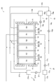
- FIG. 1 is a schematic configuration diagram of an acidic treatment liquid treatment apparatus 10 according to the first embodiment.
- the acidic treatment liquid treatment device 10 includes a tank 11, a first electrode 12, a second electrode 13, a power source 14, a first diaphragm 15, a second diaphragm 16, a first liquid passage portion 17, and a second liquid passage portion 17.
- the liquid passing unit 18 and the third liquid passing unit 19 are provided.
- the tank 11 has a space inside. In the space, the first electrode 12 and the second electrode 13 are provided separately from each other.
- the power supply 14 is a direct current power supply, and is configured to apply a voltage using the first electrode 12 and the second electrode 13 as an anode and a cathode, respectively.
- Examples of the material of the first electrode 12 include Pt, Pt plated Ti, PbO 2 coated Ti, Ti, IrO 2 coated Ti and the like.
- Examples of the material of the second electrode 13 include Pt, Pt-plated Ti, Ti and the like.
- the distance between the first electrode 12 and the second electrode 13 may be, for example, 100 cm or less.
- the space inside the tank 11 is divided into a first chamber S1, a second chamber S2, and a third chamber S3 by the first diaphragm 15 and the second diaphragm 16.
- the first diaphragm 15 divides the space inside the tank 11 into a first chamber S1 and a second chamber S2 provided closer to the second electrode 13 than the first chamber S1.
- the second diaphragm 16 partitions the first chamber S1 and the third chamber S3 provided closer to the first electrode 12 than the first chamber S1 in the space inside the tank 11.
- the first electrode 12 is provided in the third chamber S3, and the second electrode 13 is provided in the second chamber S2.
- the first liquid passing portion 17 is connected to the acidic treatment liquid storage tank 17a that stores the acidic treatment liquid, one end thereof on the downstream side of the tank 11 (the position corresponding to the first chamber S1), and the other end thereof.
- a first pipe 17b connected to the upstream side of the storage tank 17a, and one end connected to the downstream side of the acidic treatment liquid storage tank 17a and the other end upstream of the tank 11 (a position corresponding to the first chamber S1).
- a second pipe 17c connected to the second pipe 17c, and a pump 17d provided on the second pipe 17c.
- the acidic treatment liquid is passed into the first chamber S1. Is configured.
- the acidic treatment liquid circulates in the direction of the arrow in FIG. 1, that is, sequentially through the acidic treatment liquid storage tank 17a, the second pipe 17c, the first chamber S1, and the first pipe 17b.
- the acidic treatment liquid contains dichromate ions and metal cations.
- the acidic treatment liquid is typically the acidic treatment liquid after being used for the surface treatment of the metallic material.
- the metallic material indicates a metal or an alloy.
- the metallic material include aluminum, aluminum alloy, titanium, titanium alloy, stainless steel, and copper alloy.
- the aluminum alloy include those containing at least one of Cu, Fe, Zn, Mn, Mg, Cr, Ti, and Si as an alloy component.
- aluminum or aluminum alloy is preferable, and aluminum alloy is particularly preferable.
- the acidic treatment liquid before being used for the surface treatment of the metallic material contains dichromate ions. It also typically contains nitric acid with dichromate ions. When the dichromate ion is derived from the metal salt of dichromate, the metal cation corresponding to this metal salt is included. It may also contain Cr 3+ generated by reduction of dichromate ions. In addition, hydrofluoric acid, hydrofluoric acid salts, surfactants, chelating agents and the like may be further contained, if necessary.
- the metal component in the metallic material is eluted into the acidic treatment liquid.
- metal cations accumulate in the acidic treatment liquid. Therefore, in addition to the components (dichromate ion, etc.) contained in the acidic treatment liquid before being used for the surface treatment, the acidic treatment liquid after being used for the surface treatment of the metallic material is Contains metallic cations derived from the material.
- the metal cation in the acidic treatment liquid include Na + , K + , Cu 2+ , Zn 2+ , Mg 2+ , Ca 2+ , Mn 2+ , Co 2+ , Ni 2+ , Cr 3+ , Al 3+ , Fe 3+ , Examples thereof include Pb 3+ and Ti 3+ .
- the nitric acid concentration of the acidic treatment liquid may be, for example, 1 to 50% by mass.
- the dichromate ion concentration of the acidic treatment liquid may be, for example, 0.01 to 10% by mass.
- the metal cation concentration of the acidic treatment liquid may be, for example, more than 0 mass% and 10 mass% or less.
- the pH of the acidic treatment liquid may be 6 or less at 25 ° C., for example.
- the second liquid passing portion 18 is connected to the first acid aqueous solution storage tank 18a for storing the first acid aqueous solution, one end of which is connected to the downstream side of the tank 11 (a position corresponding to the second chamber S2) and the other end of which is A third pipe 18b connected to the monoacid aqueous solution storage tank 18a, a fourth pipe 18c having one end connected to the first acid aqueous solution storage tank 18a and the other end connected to the upstream side of the tank 11, A pump 18d provided on the pipe 18c is provided, and when the pump 18d is operated, the first acid aqueous solution is passed through the second chamber S2.
- the pump 18d operates, the first acid aqueous solution circulates in the direction of the arrow in FIG. 1, that is, sequentially through the first acid aqueous solution storage tank 18a, the fourth pipe 18c, the second chamber S2, and the third pipe 18b.
- the acid in the first acid aqueous solution functions as a source of hydrogen ions that transfer electrons at the second electrode 13.
- Examples of the acid include nitric acid, sulfuric acid, hydrochloric acid and the like.
- the first diaphragm 15 may be broken during the treatment with the acidic treatment liquid.
- the acid in the first acid aqueous solution is preferably the same as the acid contained in the acidic treatment liquid.
- Some acid treatment liquids contain nitric acid, and in that case, the acid in the primary acid aqueous solution is also preferably nitric acid.
- the acid concentration of the primary acid aqueous solution may be, for example, 1 to 50% by mass.
- the pH of the primary acid aqueous solution may be 6 or less at 25 ° C, for example.
- the third liquid passing portion 19 has a second acid aqueous solution storage tank 19a for storing the second acid aqueous solution, one end connected to the downstream side of the tank 11 (the position corresponding to the third chamber S3), and the other end A fifth pipe 19b connected to the diacid aqueous solution storage tank 19a, a sixth pipe 19c having one end connected to the second acid aqueous solution storage tank 19a and the other end connected to the upstream side of the tank 11, A pump 19d provided on the pipe 19c is provided, and when the pump 19d is operated, the second acid aqueous solution is passed through the third chamber S3.
- the pump 19d When the pump 19d is operated, the first acid aqueous solution circulates in the direction of the arrow in FIG. 1, that is, sequentially through the second acid aqueous solution storage tank 19a, the sixth pipe 19c, the third chamber S3, and the fifth pipe 19b.
- Examples of the acid in the second acid aqueous solution include nitric acid, sulfuric acid, hydrochloric acid and the like.
- the second diaphragm 16 may break during the treatment with the acidic treatment liquid.
- the acid in the aqueous second acid solution is preferably the same as the acid contained in the acidic treatment liquid.
- Some acid treatment liquids contain nitric acid, and in that case, the acid in the second acid aqueous solution is also preferably nitric acid.
- the acid concentration of the second acid aqueous solution may be, for example, 1 to 50% by mass.
- the pH of the aqueous secondary acid solution may be 6 or less at 25 ° C, for example.
- the second liquid passing portion 18 and the third liquid passing portion 19 are integrally configured, which simplifies the device configuration. You may aim at conversion.
- the first diaphragm 15 is a film that is permeable to at least metal cations.
- the first diaphragm 15 may be a porous membrane such as an electrolytic membrane, a biscuit plate, a cation exchange membrane, and a bipolar membrane.
- the electrolytic membrane preferably contains a fluororesin.
- the fluororesin include polytetrafluoroethylene (tetrafluorinated resin, abbreviation: PTFE), partially fluorinated olefin resin, and fluorinated olefin copolymer.
- Examples of the partially fluorinated olefin resin include polychlorotrifluoroethylene (trifluorinated resin, abbreviation: PCTFE or CTFE), polyvinylidene fluoride (abbreviation: PVDF), polyvinyl fluoride (abbreviation: PVF), and the like.
- Examples of the fluorinated olefin copolymer include perfluoroalkoxy fluororesin (abbreviation: PFA), tetrafluoroethylene-hexafluoropropylene copolymer (abbreviation: FEP), ethylene-tetrafluoroethylene copolymer (abbreviation: ETFE).
- the bipolar membrane is an ion exchange membrane having a structure in which an anion exchange layer and a cation exchange layer are bonded together.
- the cation exchange resin forming the cation exchange membrane or the cation exchange layer include resins having functional groups such as sulfo groups and carboxyl groups.
- the anion exchange resin constituting the anion exchange layer include resins having a quaternary ammonium group or primary to tertiary amino groups.
- Cations and anions can permeate the electrolytic membrane and the biscuit. Therefore, when the electrolytic membrane or the unglazed plate is used as the first diaphragm 15, when the voltage is applied with the first electrode 12 as the anode and the second electrode 13 as the cathode, it is contained in the acidic treatment liquid in the first chamber S1. While the cations move into the first acid aqueous solution in the second chamber S2 through the first diaphragm 15, the anions contained in the first acid aqueous solution in the second chamber S2 pass through the first diaphragm 15 It moves into the acidic treatment liquid in one chamber S1.
- Cation exchange membrane is permeable to cations but not anions. Therefore, when a voltage is applied using the first electrode 12 as an anode and the second electrode 13 as a cathode, the cations contained in the acidic treatment liquid in the first chamber S1 are in the second chamber S2 via the first diaphragm 15. It moves into the acid aqueous solution. On the other hand, the anion contained in the first acid aqueous solution in the second chamber S2 does not pass through the first diaphragm 15 and remains in the first acid aqueous solution.
- a cation exchange membrane is preferable.
- the first diaphragm 15 is a cation exchange membrane, the movement of anions from the second electrode 13 side (first acid aqueous solution) of the first diaphragm 15 to the first electrode 12 side (acidic treatment liquid) can be suppressed.
- the anions (NO 2 ⁇ , NO 3 ⁇ , etc.) in the primary acid aqueous solution move into the acidic treatment liquid, the concentration and composition of the acid in the acidic treatment liquid change, and this acidic treatment liquid is used as a metallic material.
- the surface treatment quality may change.
- the acidic treatment liquid may contain anions such as F ⁇ as a component for surface treatment, and when the concentration of the anions in the acidic treatment liquid decreases, the acidic treatment liquid is treated with the surface of the metallic material.
- the surface treatment quality may vary when reused for treatment. If the first diaphragm 15 is a cation exchange membrane, such movement of anions can be suppressed, and fluctuations in surface treatment quality can be suppressed.
- the electrical resistance of the first diaphragm 15 may be, for example, 100 ⁇ ⁇ dm 2 or less.
- the thickness of the first diaphragm 15 may be, for example, 1 to 10000 ⁇ m.
- the second diaphragm 16 is interposed between the first chamber S1 and the third chamber S3 to prevent the acidic treatment liquid in the first chamber S1 from contacting the first electrode 12 in the third chamber S3.
- the acidic treatment liquid is a strongly acidic liquid containing dichromate ions, if it is directly immersed in the first electrode 12, it will cause deterioration.
- the first electrode 12 is formed from a relatively expensive material such as Pt, Pt-plated Ti, PbO 2 coated Ti, Ti, and IrO 2 coated Ti as described above, if the frequency of replacement increases as the deterioration progresses, It has a large impact on costs.
- the first electrode 12 is set to the first electrode. It is configured so as not to be directly immersed in the acidic treatment liquid that is passed through the chamber S1. Thereby, the deterioration of the first electrode 12 is suppressed, and the life of the first electrode 12 can be extended. Further, when the deterioration of the first electrode 12 progresses, the peeled material from the first electrode 12 may be mixed into the treated acidic treatment liquid, which may cause a trouble when the acidic treatment liquid is reused. By suppressing the above, it is possible to effectively avoid such a trouble at the time of reuse.
- the second diaphragm 16 may be a bipolar film.
- the bipolar membrane is an ion exchange membrane having a structure in which a cation exchange layer 16a (cation exchange membrane) and an anion exchange layer 16b (anion exchange membrane) are bonded together.
- a cation exchange layer 16a cation exchange membrane
- an anion exchange layer 16b anion exchange membrane
- the cation exchange resin forming the cation exchange layer 16a include resins having functional groups such as sulfo groups and carboxyl groups.
- the anion exchange resin forming the anion exchange layer 16b include resins having a quaternary ammonium group or primary to tertiary amino groups.
- the anion exchange layer 16b is arranged on the side facing the first electrode 12, and the cation exchange membrane is on the side facing the second electrode 13. 16a may be arranged. Since the anion-exchange layer 16b forming the bipolar membrane has weaker corrosion resistance than the cation-exchange layer 16a, the cation-exchange layer 16a is disposed on the side in contact with the acidic treatment liquid to stabilize the treatment capacity in the long term. Can be maintained.
- a monovalent cation selective permeation membrane capable of selectively permeating only monovalent cations may be used.
- the monovalent cation selective permeation film is cheaper than the bipolar film described above, and is effective for reducing the device cost.
- the electric resistance of the second diaphragm 16 may be, for example, 100 ⁇ ⁇ dm 2 or less.
- the thickness of the second diaphragm 16 may be, for example, 1 to 10000 ⁇ m.
- the acidic treatment liquid treatment device 10 is used for treating an acidic treatment liquid containing dichromate ions and metal cations. Specifically, it is used to remove metal cations from this acidic treatment liquid.
- an example of an acidic treatment liquid treatment method using the acidic treatment liquid treatment apparatus 10 will be described with reference to FIG.
- a nitric acid aqueous solution is used as the first acid aqueous solution and the second acid aqueous solution, and contains nitric acid, dichromate ions, and metal cations Cr 3+ , Cu 2+ , Na + , Al 3+ , Fe 3+ , Zn 2+ . Treat the acidic treatment liquid.
- the pump 17d is operated to pass the acidic treatment liquid into the first chamber S1, the pump 18d is activated to pass the aqueous acid solution into the second chamber S2, and the pump 19d is activated. It is operated and the acidic treatment liquid is passed through the third chamber S3.
- the power source 14 causes the first electrode 12 to serve as an anode and a second electrode. A voltage is applied using the two electrodes 13 as a cathode.
- the following reactions 1-1 to 1-2 mainly proceed at the first electrode 12, and the following reactions 2-1 to 2-2 mainly proceed at the second electrode 13. move on. Further, cations (H 3 O + , Cr 3+ , Cu 2+ , Na + , Al 3+ , Fe 3+ , Zn 2+ ) in the acidic treatment liquid permeate the first diaphragm 15 and are attracted to the second electrode 13 side. And move into the aqueous primary acid solution.
- the anions (NO 2 ⁇ , NO 3 ⁇ ) in the first acid aqueous solution are attracted to the first electrode 12 side, It permeates through the diaphragm 15 and the second diaphragm 16, and moves into the second acid aqueous solution through the acidic treatment liquid.
- Reaction 1-1 NO 2 ⁇ + H 2 O ⁇ NO 3 ⁇ + 2H + + 2e ⁇
- Reaction 1-2 2H 2 O ⁇ O 2 + 4H + + 4e ⁇
- Reaction 2-1 NO 3 ⁇ + 2H + + 2e ⁇ ⁇ NO 2 ⁇ + H 2 O
- Reaction 2-2 2H + + 2e ⁇ ⁇ H 2
- the amount of the acidic treatment liquid passed through the first chamber S1 may be, for example, 100 t / hr or less.
- the temperature of the acidic treatment liquid may be, for example, 1 to 80 ° C.
- the amount of the first acid aqueous solution passed through the second chamber S2 may be, for example, 100 t / hr or less.
- the temperature of the aqueous primary acid solution may be, for example, 1 to 80 ° C.
- the amount of the second acid aqueous solution passed through the third chamber S3 may be, for example, 100 t / hr or less.
- the temperature of the second aqueous acid solution may be, for example, 1-80 ° C.
- the voltage applied by the power supply 14, for example, 0V may be less super 1000V, current density may be for example 0A / dm 2 Ultra 100A / dm 2 or less.
- the metal cations in the acidic treatment liquid permeate the first diaphragm 15 and move into the first acid aqueous solution, so that the metal cations are removed from the acidic treatment liquid.
- the dichromate ion in the acidic treatment liquid tends to be attracted to the first electrode 12 side because it is an anion, but the acidic treatment is performed by the bipolar membrane of the second diaphragm 16 or the monovalent cation selective permeable membrane. Stay in the liquid.
- the acidic treatment liquid does not contact the first electrode 12 that is the anode as described above, and does not contact the second electrode 13 that is the cathode. Therefore, it is possible to suppress the side reaction in which the dichromate ion (hexavalent chromium) in the acidic treatment liquid is reduced. Similarly, it is possible to suppress a side reaction in which nitric acid (NO 3 ⁇ ) in the acidic treatment liquid is reduced. Therefore, the metal cations in the acidic treatment liquid can be removed without reducing hexavalent chromium and nitric acid. It is also possible to remove metal cations such as aluminum ions, which cannot be removed by the electrolytic deposition method.
- the acidic treatment liquid after removing the metal cations as described above can be reused for surface treatment without waste.
- the metal cation concentration can be kept low during reuse, the risk of mixing of metal cations due to surface treatment can be reduced, and furthermore, highly pure metal can be recovered.
- nitric acid which is the same as the acid contained in the acidic treatment liquid is selected as the acid of the first acid aqueous solution and the second acid aqueous solution
- hydrogen ions that exchange electrons are supplied and, by any chance, the first diaphragm 15
- the second diaphragm 16 is broken, it is possible to prevent the acid treatment liquid from being mixed with a different type of acid and affecting the surface treatment quality.
- a cation exchange membrane is selected as the first diaphragm 15, it is possible to prevent the nitric acid concentration in the acidic treatment liquid from fluctuating when nitric acid is mixed into the acidic treatment liquid from the first acid aqueous solution.
- water H 3 O + or H + ⁇ nH 2 O moves from the acidic treatment liquid to the first acid aqueous solution on the cathode side. Therefore, the increased water content may be removed from the primary acid aqueous solution during or after the treatment of the acidic treatment liquid. This makes it possible to suppress the increase in the liquid amount and continue to use the primary acid aqueous solution.
- the removal of water may be carried out by a general heating concentration method, or may be carried out by heating evaporation by sunlight or air drying.
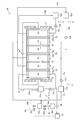
- FIG. 2 is a schematic configuration diagram of the acidic treatment liquid treatment apparatus 20 according to the second embodiment.
- the same reference numerals will be given to the configurations corresponding to the above-described embodiments, and duplicate descriptions will be omitted as appropriate.
- a plurality of treatment units including the first chamber S1 and the second chamber S2 adjacent to each other are provided between the first electrode 12 and the second electrode 13.
- two processing units, a first processing unit U1 and a second processing unit U2 are provided between the first electrode 12 and the second electrode 13.
- first processing unit U1 and the second processing unit U2 a pair of the first chamber S1 and the second chamber S2 are arranged with the first diaphragm 15 interposed therebetween.
- the second chamber S2 of the first processing unit and the first chamber S1 of the second processing unit U2 are arranged with the second diaphragm 16 interposed therebetween.
- the acidic treatment liquid and the first acid aqueous solution are passed through the first liquid passing portion 17 and the second liquid passing portion 18, respectively, into the first chamber S1 and the second chamber S2 of each such processing unit.
- the first chamber S1 of the first processing unit U1 located closest to the first electrode 12 among the plurality of processing units is disposed adjacent to the third chamber S3 including the first electrode 12 via the second diaphragm 16.
- the second acid aqueous solution is passed through the third liquid passage 19 into the third chamber S3.
- the first electrode 12 is isolated from the acidic treatment liquid that is passed through the first chamber S1 by the second diaphragm 16, so that the deterioration of the first electrode 12 can be suppressed and the long life can be suppressed. Can be achieved.
- the second chamber S2 of the second processing unit U2 located closest to the second electrode 13 among the plurality of processing units is adjacent to the fourth chamber S4 including the second electrode 13 via the third diaphragm 23. Will be placed.
- the third acid aqueous solution is passed through the fourth liquid passage 21 into the fourth chamber S4.
- the fourth liquid passing portion 21 is connected to the acid aqueous solution storage tank 21a for storing the third acid aqueous solution, one end is connected to the downstream side of the tank 11 (the position corresponding to the fourth chamber S4), and the other end is stored the acid aqueous solution.
- the seventh pipe 21b connected to the tank 21a, the eighth pipe 21c having one end connected to the acid aqueous solution storage tank 21a and the other end connected to the upstream side of the tank 11 are provided on the eighth pipe 21c.
- a pump 21d and when the pump 21d is operated, the third acid aqueous solution is passed through the fourth chamber S4.
- the pump 21d When the pump 21d is operated, the first acid aqueous solution circulates in the arrow direction in FIG. 2, that is, sequentially through the acid aqueous solution storage tank 21a, the eighth pipe 21c, the fourth chamber S4, and the seventh pipe 21b.
- Examples of the acid in the aqueous solution of tertiary acid include nitric acid, sulfuric acid, hydrochloric acid and the like.
- the acid concentration of the aqueous third acid solution may be, for example, 1 to 50% by mass.
- the pH of the aqueous solution of tertiary acid may be 6 or less at 25 ° C, for example.
- the third diaphragm 23 is interposed between the second chamber S2 and the fourth chamber S4 of the second unit U2, so that the third diaphragm 23 is connected to the first chamber S1 on the second electrode 13 provided in the fourth chamber S4. It is possible to prevent the metal ions that have moved from the acidic treatment liquid to be deposited from depositing. Thereby, the quality on the second electrode 13 can be favorably maintained for a long period of time.
- a bipolar film can be used as the third diaphragm 23.
- the bipolar membrane is an ion exchange membrane having a structure in which a cation exchange layer 23a (cation exchange membrane) and an anion exchange layer 23b (anion exchange membrane) are bonded together.
- a cation exchange layer 23a cation exchange membrane
- an anion exchange layer 23b anion exchange membrane
- the cation exchange resin forming the cation exchange layer 23a include resins having functional groups such as sulfo groups and carboxyl groups.
- the anion exchange resin forming the anion exchange layer 23b include resins having a quaternary ammonium group or primary to tertiary amino groups.
- a monovalent cation selective permeation membrane capable of selectively permeating only monovalent cations may be used.
- the monovalent cation selective permeation film is cheaper than the bipolar film described above, and is effective for reducing the device cost.
- the electrical resistance of the third diaphragm 23 may be, for example, 100 ⁇ ⁇ dm 2 or less.
- the thickness of the third diaphragm 23 may be, for example, 1 to 10000 ⁇ m.
- the acidic treatment liquid treatment apparatus 20 by providing a plurality of treatment units U1 and U2 between the first electrode 12 and the second electrode 13, the acid treatment is performed while the area of the first electrode 12 and the second electrode 13 is kept small.
- the processing capacity of the processing liquid can be increased.
- the area of the first electrode 12 and the second electrode 13 can be kept small, the current capacity can be kept relatively small even when the number of processing units is increased, and the increase in size of the power supply 14 can be minimized. It can be suppressed and the power cost can be reduced.
- Even when a plurality of processing units are provided since the device configuration is compact, it can be accommodated in a limited installation space, and an increase in the number of parts such as an increase in the number of power cables can be suppressed. it can. This is also advantageous in terms of cost.
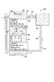
- FIG. 3 is a schematic configuration diagram of the acidic treatment liquid treatment apparatus 30 according to the third embodiment.
- the same reference numerals will be given to the configurations corresponding to the above-described embodiments, and duplicate descriptions will be omitted as appropriate.
- a plurality of treatment units including the first chamber S1 and the second chamber S2 adjacent to each other are provided between the first electrode 12 and the second electrode 13 as in the acidic treatment liquid treatment device 20 described above. It is provided.
- two processing units, a first processing unit U1 and a second processing unit U2 are provided between the first electrode 12 and the second electrode 13.
- first processing unit U1 and the second processing unit U2 a pair of the first chamber S1 and the second chamber S2 are arranged with the first diaphragm 15 interposed therebetween.
- the second chamber S2 of the first processing unit and the first chamber S1 of the second processing unit U2 are arranged with the second diaphragm 16 interposed therebetween.
- the acidic treatment liquid and the first acid aqueous solution are passed through the first liquid passing portion 17 and the second liquid passing portion 18, respectively, into the first chamber S1 and the second chamber S2 of each such processing unit.
- the first chamber S1 of the first processing unit U1 located closest to the first electrode 12 among the plurality of processing units is disposed adjacent to the third chamber S3 including the first electrode 12 via the second diaphragm 16.
- the second acid aqueous solution is passed through the third liquid passage 19 into the third chamber S3.
- the first electrode 12 is isolated from the acidic treatment liquid that is passed through the first chamber S1 by the second diaphragm 16, so that the deterioration of the first electrode 12 can be suppressed and the long life can be suppressed. Can be achieved.
- the second chamber S2 of the second processing unit U2 located closest to the second electrode 13 among the plurality of processing units is adjacent to the fourth chamber S4 including the second electrode 13 via the third diaphragm 23. Will be placed.
- the third acid aqueous solution is passed through the fourth liquid passage 21 into the fourth chamber S4.
- the fourth liquid passing portion 21 is connected to the acid aqueous solution storage tank 21a for storing the third acid aqueous solution, one end is connected to the downstream side of the tank 11 (the position corresponding to the fourth chamber S4), and the other end is stored the acid aqueous solution.
- a seventh pipe 21b connected to the tank 21a, an eighth pipe 21c having one end connected to the acid aqueous solution storage tank 21a and the other end connected to the upstream side of the tank 11 are provided on the eighth pipe 21c.
- a pump 21d and when the pump 21d is operated, the third acid aqueous solution is passed through the fourth chamber S4.
- the pump 21d When the pump 21d is operated, the first acid aqueous solution circulates in the arrow direction in FIG. 2, that is, sequentially through the acid aqueous solution storage tank 21a, the eighth pipe 21c, the fourth chamber S4, and the seventh pipe 21b.
- Examples of the acid in the aqueous solution of tertiary acid include nitric acid, sulfuric acid, hydrochloric acid and the like.
- the acid concentration of the aqueous third acid solution may be, for example, 1 to 50% by mass.
- the pH of the aqueous solution of tertiary acid may be 6 or less at 25 ° C, for example.
- the acid treatment liquid treatment device 30 additionally adds the acid aqueous solution to the circulation flow path 25 (the acid aqueous solution storage tank 21a, the eighth pipe 21c, the fourth chamber S4, the seventh pipe 21b) through which the third acid aqueous solution circulates.
- An acid aqueous solution supply unit 35 that can supply the acid aqueous solution and a discharge unit 36 that can discharge the acid aqueous solution from the circulation channel 25 are provided.
- the acid aqueous solution supply unit 35 serves as a supply source of the acid aqueous solution to the circulation channel 25, and an acid aqueous solution replenishment tank 35a, and a pipe 35b connecting the downstream side of the acid aqueous solution replenishment tank 35a and the upstream side of the acid aqueous solution storage tank 21a.
- the additional supply of the acid aqueous solution is performed by opening the valve 35c.
- the aqueous acid solution can be additionally supplied from the outside by the aqueous acid solution supply unit 35 to the third aqueous acid solution which is passed through the fourth chamber S4. Therefore, even if the acid concentration in the acid aqueous solution in the fourth chamber S4 decreases due to the processing reaction proceeding in the tank 11 and the processing capacity decreases, the acid aqueous solution is additionally supplied from the outside.
- the acid concentration can be increased to restore or maintain throughput. As a result, it is possible to reduce the cost by suppressing the consumption of the third acid aqueous solution in the circulation channel 25 and reducing the frequency of replacement. Further, when the acid concentration in the acid aqueous solution decreases, the voltage between the first electrode 12 and the second electrode 13 increases.
- the first electrode by additionally supplying the acid aqueous solution to increase the acid concentration as described above, the first electrode The voltage between the electrodes 12 and the second electrode 13 can also be suppressed. As a result, the power consumption of the power supply 14 can be suppressed, which is also effective in reducing the power cost.
- the acid concentration detection unit 38 detects the acid concentration of the third acid aqueous solution in the fourth chamber S4.
- the acid concentration detected by the acid concentration detector 38 is sent to the supply controller 37 as an electric signal.
- the supply control unit 37 is a control unit including an electronic arithmetic device such as a computer, and supplies the aqueous acid solution supply unit 35 so that the acid concentration detected by the acid concentration detection unit 38 falls within a predetermined concentration range set in advance. By controlling (the opening degree of the valve 35c), the additional supply amount of the acid aqueous solution is adjusted. As a result, the acid concentration of the third acid aqueous solution circulating in the fourth chamber S4 is maintained within the predetermined concentration range, and suitable processing capacity can be obtained for a long period of time.
- the discharge unit 36 is configured to be able to discharge the third acid aqueous solution circulating in the circulation flow path 25 to the outside.
- the discharge part 36 has a discharge line 36b communicating with the discharge port 36a.
- the discharge line 36b communicates the pipe 35d with the discharge line 36b by a three-way valve 36d provided at a branch point between the discharge line 36b and the pipe 35d, so that the third acid aqueous solution flowing through the circulation passage 25 is discharged to the discharge port 36a. It can be discharged from the outside.
- the discharging operation of the aqueous acid solution by the discharging unit 36 may be performed manually by a worker or may be automatically controlled. In the latter case, for example, the volume of the acid aqueous solution flowing through the circulation flow channel 25 may be monitored, and the discharge operation may be performed when the volume exceeds a predetermined volume.
- the acid aqueous solution supply unit 35 additionally supplies the acid aqueous solution to the circulation flow channel 25, or the discharge unit 36 discharges the acid aqueous solution from the circulation flow channel 25.
- sulfuric acid is used as the acid in the tertiary acid aqueous solution
- these configurations may be omitted.
- Sulfuric acid is hardly consumed by the reduction reaction at the second electrode 13, which is the cathode, and is therefore consumed less than an aqueous acid solution such as nitric acid, which is consumed by the reduction reaction at the second electrode 13, such that the above-described acid is used. Even if there is no additional supply or discharge of the aqueous solution, stable treatment performance can be obtained over a long period of time.
- an acidic treatment capable of improving the quality of the acidic treatment liquid after the treatment is achieved while suppressing the deterioration of the electrode to prolong the life and reduce the cost.
- a liquid processing apparatus and an acidic processing liquid processing method can be provided.
- At least one embodiment of the present invention can be used for an acidic treatment liquid treatment apparatus and an acidic treatment liquid treatment method for treating an acidic treatment liquid containing a dichromate ion and a metal cation.
- Acidic Treatment Liquid Treatment Device 11 Tank 12 First Electrode 13 Second Electrode 14 Power Supply 15 First Separator 16 Second Separator 17 First Liquid Passing Part 18 Second Liquid Passing Part 19 Third Liquid Passing Part 20 Acidic Treatment Liquid Processing Device 21 Fourth Liquid Passing Part 23 Third Separating Membrane 25 Circulating Flow Path 30 Acid Treatment Liquid Processing Device 35 Acid Aqueous Solution Supply Unit 36 Discharge Unit 37 Supply Control Unit
Landscapes
- Chemical & Material Sciences (AREA)
- Engineering & Computer Science (AREA)
- Water Supply & Treatment (AREA)
- Chemical Kinetics & Catalysis (AREA)
- Urology & Nephrology (AREA)
- Health & Medical Sciences (AREA)
- Mechanical Engineering (AREA)
- Metallurgy (AREA)
- Organic Chemistry (AREA)
- Materials Engineering (AREA)
- General Chemical & Material Sciences (AREA)
- Water Treatment By Electricity Or Magnetism (AREA)
- Separation Using Semi-Permeable Membranes (AREA)
- Cleaning And De-Greasing Of Metallic Materials By Chemical Methods (AREA)
Abstract
Provided is an apparatus for treating an acidic treatment solution, wherein a space between a first electrode and a second electrode spaced apart from each other is divided into a first chamber, a second chamber, and a third chamber by a first diaphragm and a second diaphragm. An acidic treatment solution containing dichromate ions and metal cations is passed through the first chamber, a first acid aqueous solution is passed through the second chamber, a second acid aqueous solution is passed through the third chamber, and a voltage is applied using the first electrode as a positive electrode and the second electrode as a negative electrode.
Description
本開示は、二クロム酸イオン及び金属陽イオンを含む酸性処理液を処理するための酸性処理液処理装置、及び、酸性処理液処理方法に関する。
The present disclosure relates to an acidic treatment liquid treatment apparatus for treating an acidic treatment liquid containing a dichromate ion and a metal cation, and an acidic treatment liquid treatment method.
軽量で強度に優れたアルミニウム合金は、例えば航空機のような工業製品に用いられている。航空機部品の製造段階では、上記部品に対する防錆処理の一環として、硝酸等を含む酸性処理液を用いて汚れや酸化皮膜を除去する表面処理が行われている。この酸性処理液には、耐食性を高めるために6価クロム(二クロム酸イオン)を含有させることがある。
Aluminum alloy, which is lightweight and has excellent strength, is used in industrial products such as aircraft. At the manufacturing stage of aircraft parts, as a part of the rustproofing treatment for the above-mentioned parts, surface treatment for removing dirt and oxide film is performed using an acid treatment liquid containing nitric acid and the like. This acidic treatment liquid may contain hexavalent chromium (dichromate ion) in order to improve corrosion resistance.
酸性処理液は例えば部品の製造ライン上における表面処理に繰り返し使用されるが、次第に、酸性処理液中にアルミニウム合金由来の金属成分(アルミニウム、銅等)を含む不純物が蓄積する。酸性処理液に含まれる不純物が増加すると、処理反応の阻害や表面処理の際に不純物が部品の表面に付着し、表面処理の品質(耐食性等)低下の要因となる。そのため、所定のタイミングで酸性処理液を産業廃棄物として廃液し、新たに酸性処理液を建浴する必要が有り、環境負荷になるとともに酸性処理液の交換に時間及びコストを要している。
The acidic treatment liquid is repeatedly used, for example, for surface treatment on the manufacturing line of parts. Gradually, impurities containing metal components (aluminum, copper, etc.) derived from aluminum alloys accumulate in the acidic treatment liquid. When the amount of impurities contained in the acidic treatment liquid increases, the treatment reaction is hindered and the impurities adhere to the surface of the component during the surface treatment, which causes deterioration of surface treatment quality (corrosion resistance, etc.). For this reason, it is necessary to drain the acidic treatment liquid as industrial waste at a predetermined timing and newly build a bath of the acidic treatment liquid, which becomes an environmental load and requires time and cost for exchanging the acidic treatment liquid.
一方、有機酸を含む銅のエッチング液から銅イオンを除去する方法として、電気透析法を利用した方法が提案されている(特許文献1)。
On the other hand, a method using an electrodialysis method has been proposed as a method for removing copper ions from a copper etching solution containing an organic acid (Patent Document 1).
本発明者らは、上記の表面処理によって不純物が蓄積した酸性処理液を長寿命化(交換頻度を低減)するために、電解析出法により酸性処理液から金属成分を除去することを検討した。検討においては、図4に示すような酸性処理液処理装置100を用いた。
The present inventors examined removing the metal component from the acidic treatment liquid by electrolytic deposition in order to extend the life of the acidic treatment liquid in which impurities were accumulated by the above surface treatment (reduce the frequency of exchange). .. In the examination, an acidic treatment liquid treatment apparatus 100 as shown in FIG. 4 was used.
酸性処理液処理装置100は、内部に空間を有する槽101と、槽101の内部の空間を第一室S1と第二室S2とに区画する隔膜103と、第一室S1内に設けられた陽極105と、第二室S2内に設けられた陰極107と、酸性処理液を通液する通液部110とを備える。通液部110は、酸性処理液を貯留する貯留槽111と、貯留槽111と第二室S2とを接続する第一配管113と、第一配管113に設けられたポンプ115と、第二室S2と第一室S1とを接続する第二配管117と、第一室S1と貯留槽111とを接続する第三配管119とを備えており、ポンプ115を作動させたときに、酸性処理液が貯留槽111、第二室S2及び第一室S1を順次通って循環するように構成されている。
The acidic treatment liquid treatment apparatus 100 is provided in a tank 101 having a space therein, a diaphragm 103 for partitioning the space inside the tank 101 into a first chamber S1 and a second chamber S2, and the first chamber S1. It is provided with an anode 105, a cathode 107 provided in the second chamber S2, and a liquid passage portion 110 for passing an acidic treatment liquid. The liquid passage unit 110 includes a storage tank 111 that stores the acidic treatment liquid, a first pipe 113 that connects the storage tank 111 and the second chamber S2, a pump 115 provided in the first pipe 113, and a second chamber. The second pipe 117 connecting the S2 and the first chamber S1 and the third pipe 119 connecting the first chamber S1 and the storage tank 111 are provided, and when the pump 115 is operated, the acidic treatment liquid. Is configured to circulate through the storage tank 111, the second chamber S2, and the first chamber S1 sequentially.
この酸性処理液処理装置100では、チタン又は白金めっきを施したチタンを陽極105及び陰極107として用い、貯留槽111に銅イオンを含む酸性処理液を収容する。次いでポンプ115を作動させて酸性処理液を通液するとともに、陽極105及び陰極107に電圧を印加する。これにより、図4に示すように、銅イオン等の陽イオンが第一室S1から隔膜103を介して第二室S2に移動する。第二室S2内の銅イオンは陰極107表面にて還元され、陰極107表面に析出し、銅膜120を形成する。こうして酸性処理液から銅成分が電気化学的に除去される。
In this acidic treatment liquid treatment device 100, titanium or platinum-plated titanium is used as an anode 105 and a cathode 107, and an acidic treatment liquid containing copper ions is stored in a storage tank 111. Next, the pump 115 is operated to pass the acidic treatment liquid, and a voltage is applied to the anode 105 and the cathode 107. As a result, as shown in FIG. 4, cations such as copper ions move from the first chamber S1 to the second chamber S2 via the diaphragm 103. Copper ions in the second chamber S2 are reduced on the surface of the cathode 107 and are deposited on the surface of the cathode 107 to form a copper film 120. Thus, the copper component is electrochemically removed from the acidic treatment liquid.
ここで、酸性処理液処理装置100の陽極105及び陰極107は、強酸性である酸性処理液に直接接触するため劣化が進行する。そのため陽極105及び陰極107は、劣化度がある程度に達したタイミングで交換等の処置を施す必要がある。陽極105及び陰極107は、上述のようにチタン又は白金めっきを施したチタンという高価な材料を使用しているため、このような処置は運転コストや消耗品コストに影響を与える。また陽極105及び陰極107に劣化が生じると剥離物などの不純物が酸性処理液に混ざる可能性があり、処理後の酸性処理液を表面処理に再使用した際にトラブルをもたらす要因になり得る。
Here, since the anode 105 and the cathode 107 of the acidic treatment liquid treatment apparatus 100 are in direct contact with the acidic treatment liquid that is strongly acidic, deterioration progresses. Therefore, the anode 105 and the cathode 107 need to be replaced or the like when the deterioration degree reaches a certain level. Since the anode 105 and the cathode 107 use an expensive material such as titanium or platinum plated with titanium as described above, such a treatment affects the operating cost and the consumable cost. Further, when the anode 105 and the cathode 107 are deteriorated, impurities such as peeled substances may be mixed with the acid treatment liquid, which may cause a trouble when the acid treatment liquid after the treatment is reused for the surface treatment.
本発明の少なくとも一実施形態は上述の事情に鑑みなされたものであり、電極の劣化を抑制することで長寿命化及び低コスト化を図るとともに、処理後の酸性処理液の品質を向上可能な酸性処理液処理装置、及び、酸性処理液処理方法を提供することを目的とする。
At least one embodiment of the present invention has been made in view of the above-mentioned circumstances, and it is possible to improve the quality of the acidic treatment liquid after the treatment while suppressing the deterioration of the electrode to prolong the life and reduce the cost. An object is to provide an acidic treatment liquid treatment apparatus and an acidic treatment liquid treatment method.
(1)本発明の少なくとも一実施形態に係る酸性処理液処理装置は上記課題を解決するために、
内部に空間を有する槽と、
前記空間内に互いに離れて設けられた第一電極及び第二電極と、
前記第一電極を陽極、前記第二電極を陰極として電圧を印加する電源と、
前記空間のうち前記第一電極及び前記第二電極の間に設けられた第一室と、前記第一室より前記第二電極側に設けられた第二室とを区画する、金属陽イオンを透過可能な第1隔膜と、
前記空間のうち前記第一室と、前記第一室より前記第一電極側に設けられた第三室とを区画する第二隔膜と、
前記第一室内に二クロム酸イオン及び金属陽イオンを含む酸性処理液を通液する第一通液部と、
前記第二室内に、第一酸水溶液を通液する第二通液部と、
前記第三室内に、第二酸水溶液を通液する第三通液部と、
を備える。 (1) In order to solve the above problems, an acidic treatment liquid treatment apparatus according to at least one embodiment of the present invention is
A tank with a space inside,
A first electrode and a second electrode provided apart from each other in the space,
A power source for applying a voltage using the first electrode as an anode and the second electrode as a cathode;
A first chamber provided between the first electrode and the second electrode in the space and a second chamber provided on the second electrode side from the first chamber are partitioned, and metal cations are A permeable first diaphragm,
Of the space, the first chamber and a second diaphragm that partitions the third chamber provided on the first electrode side from the first chamber,
A first liquid passing portion for passing an acidic treatment liquid containing dichromate ions and metal cations into the first chamber,
In the second chamber, a second liquid passing portion for passing a first acid aqueous solution,
In the third chamber, a third liquid passing part for passing a second acid aqueous solution,
Equipped with.
上記(1)の構成によれば、槽の内部に設けられた空間は、第一隔膜及び第二隔膜によって第一室~第三室に区画される。酸性処理液が通液される第一室は、第一隔膜及び第二隔膜によって第二室及び第三室から区画されるため、第一電極及び第二電極が酸性処理液に直接浸漬されない。そのため、第一電極及び第二電極の劣化を抑制することで長寿命化が可能となり、交換頻度を減らすことで低コスト化を図ることができる。また第一電極及び第二電極の劣化による剥離による酸性処理液の汚染も防げるため、処理後の酸性処理液の品質低下も防止できる。
According to the configuration of (1) above, the space provided inside the tank is divided into the first chamber to the third chamber by the first diaphragm and the second diaphragm. The first chamber through which the acidic treatment liquid is passed is separated from the second chamber and the third chamber by the first diaphragm and the second diaphragm, so that the first electrode and the second electrode are not directly immersed in the acidic treatment liquid. Therefore, it is possible to extend the life by suppressing the deterioration of the first electrode and the second electrode, and it is possible to reduce the cost by reducing the replacement frequency. In addition, since the acidic treatment liquid can be prevented from being contaminated due to peeling due to deterioration of the first electrode and the second electrode, deterioration of the quality of the acidic treatment liquid after the treatment can be prevented.
(2)幾つかの実施形態では上記(1)の構成において、
前記第二室と、前記第二室より前記第二電極側に設けられた第四室とを区画する、金属陽イオンを透過しない第三隔膜と、
前記第四室に、第三酸水溶液を通液する第四通液部を更に備える。 (2) In some embodiments, in the configuration of (1) above,
The second chamber and a third chamber that partitions the fourth chamber provided on the second electrode side from the second chamber, and is impermeable to metal cations,
The said 4th chamber is further equipped with the 4th liquid passing part which lets a 3rd aqueous solution pass.
上記(2)の構成によれば、第二室より第二電極側に金属陽イオンを透過しない第三隔膜を介して第四室を設けることで、第一室に通液される酸性処理液から移動した金属陽イオンは第四室に透過することなく、第二室に留まる。これにより、金属イオンが第二電極上に析出することを防止できるため、第二電極上の析出物の除去作業が省略することが可能となる。
According to the above configuration (2), by providing the fourth chamber on the second electrode side from the second chamber via the third diaphragm that does not permeate the metal cations, the acidic treatment liquid passed through the first chamber. The metal cations that have migrated from the chamber remain in the second chamber without permeating into the fourth chamber. As a result, metal ions can be prevented from depositing on the second electrode, so that the work of removing deposits on the second electrode can be omitted.
(3)幾つかの実施形態では上記(1)又は(2)の構成において、
前記第一隔膜を介して互いに隣り合う前記第一室及び第二室を含む処理ユニットが、前記第二隔膜を介して前記第一電極及び前記第二電極の間に複数設けられる。 (3) In some embodiments, in the configuration of (1) or (2) above,
A plurality of processing units including the first chamber and the second chamber, which are adjacent to each other via the first diaphragm, are provided between the first electrode and the second electrode via the second diaphragm.
上記(3)の構成によれば、第一電極及び第二電極間に複数の処理ユニットを設けることで、第一電極及び第二電極の面積を小さく抑えながらも、酸性処理液の処理容量を増大することができる。これにより第一電極及び第二電極に高価な材料を採用した場合であっても装置コストを効果的に抑制しながら、大容量の処理装置を実現できる。
According to the above configuration (3), by providing a plurality of treatment units between the first electrode and the second electrode, the treatment capacity of the acidic treatment liquid can be reduced while keeping the areas of the first electrode and the second electrode small. Can be increased. This makes it possible to realize a large-capacity processing apparatus while effectively suppressing the apparatus cost even when expensive materials are used for the first electrode and the second electrode.
(4)幾つかの実施形態では上記(1)から(3)のいずれか一構成において、
前記第一隔膜は陽イオン交換膜を含む。 (4) In some embodiments, in any one of the configurations (1) to (3) above,
The first diaphragm includes a cation exchange membrane.
前記第一隔膜は陽イオン交換膜を含む。 (4) In some embodiments, in any one of the configurations (1) to (3) above,
The first diaphragm includes a cation exchange membrane.
上記(4)の構成によれば、酸水溶液中の陰イオン(硝酸イオン等)が酸性処理液に混入することを効果的に抑制できる。
According to the configuration of (4) above, it is possible to effectively suppress the anion (nitrate ion, etc.) in the acid aqueous solution from being mixed in the acidic treatment liquid.
(5)幾つかの実施形態では上記(4)の構成において、
前記陽イオン交換膜は陽イオン選択透過膜である。 (5) In some embodiments, in the configuration of (4) above,
The cation exchange membrane is a cation selective permeable membrane.
前記陽イオン交換膜は陽イオン選択透過膜である。 (5) In some embodiments, in the configuration of (4) above,
The cation exchange membrane is a cation selective permeable membrane.
上記(5)の構成によれば、陽イオン交換膜として比較的安価な陽イオン選択透過膜を採用することで、より効果的にコスト削減が可能となる。例えば陽イオン交換膜は、銅イオン(2価)のような多価陽イオンを交換可能な多価陽イオン交換膜である。
According to the configuration of (5) above, the cost can be more effectively reduced by using a relatively inexpensive cation selective permeable membrane as the cation exchange membrane. For example, the cation exchange membrane is a polyvalent cation exchange membrane capable of exchanging polyvalent cations such as copper ions (divalent).
(6)幾つかの実施形態では上記(1)から(5)のいずれか一構成において、
前記第二隔膜はバイポーラ膜若しくは一価陽イオン選択透過膜を含む。 (6) In some embodiments, in any one of the configurations (1) to (5) above,
The second diaphragm includes a bipolar membrane or a monovalent cation selective permeable membrane.
前記第二隔膜はバイポーラ膜若しくは一価陽イオン選択透過膜を含む。 (6) In some embodiments, in any one of the configurations (1) to (5) above,
The second diaphragm includes a bipolar membrane or a monovalent cation selective permeable membrane.
上記(6)の構成によれば、第一室と第三室とを区画する第二隔膜としてバイポーラ膜若しくは一価陽イオン選択透過膜を採用することで、第一室の酸性処理液中の陰イオン(二クロム酸イオンや硝酸イオン等)が第三室側に移動することを抑制しながら、酸性処理液を第一電極から隔離できる。
According to the configuration of the above (6), by adopting a bipolar membrane or a monovalent cation selective permeation membrane as the second diaphragm partitioning the first chamber and the third chamber, the acid treatment liquid in the first chamber The acidic treatment liquid can be isolated from the first electrode while suppressing the movement of anions (dichromate ions, nitrate ions, etc.) to the third chamber side.
(7)幾つかの実施形態では上記(6)の構成において、
前記バイポーラ膜は、前記第一電極に対向する陰イオン交換層と、前記第二電極に対向する陽イオン交換層とを含む。 (7) In some embodiments, in the configuration of (6) above,
The bipolar membrane includes an anion exchange layer facing the first electrode and a cation exchange layer facing the second electrode.
前記バイポーラ膜は、前記第一電極に対向する陰イオン交換層と、前記第二電極に対向する陽イオン交換層とを含む。 (7) In some embodiments, in the configuration of (6) above,
The bipolar membrane includes an anion exchange layer facing the first electrode and a cation exchange layer facing the second electrode.
上記(7)の構成によれば、陰イオン交換層を構成する陽イオン交換層はカチオン交換膜に比べて耐食性が弱いため、陽イオン交換層が酸性処理液に触れる側に配置されることで、長期的に処理能力を安定に維持できる。
According to the configuration of (7) above, since the cation exchange layer constituting the anion exchange layer has weaker corrosion resistance than the cation exchange membrane, the cation exchange layer is disposed on the side in contact with the acidic treatment liquid. , Can maintain stable processing capacity in the long term.
(8)幾つかの実施形態では上記(2)の構成において、
前記第四室の酸濃度を検出する酸濃度検出部と、
前記酸濃度検出部の検出結果に基づいて、前記第四室に対して酸水溶液を追加的に供給する酸水溶液供給部と、
を備える。 (8) In some embodiments, in the configuration of (2) above,
An acid concentration detection unit for detecting the acid concentration of the fourth chamber,
Based on the detection result of the acid concentration detection unit, an acid aqueous solution supply unit that additionally supplies an acid aqueous solution to the fourth chamber,
Equipped with.
上記(8)の構成によれば、第四室の酸水溶液の酸濃度に基づいて、第四室に対して酸水溶液が追加的に供給される。これにより、第四室を循環する酸水溶液の酸濃度が適切な濃度範囲に維持され、好適な処理能力が長期にわたって得られる。
According to the above configuration (8), the aqueous acid solution is additionally supplied to the fourth chamber based on the acid concentration of the aqueous acid solution in the fourth chamber. As a result, the acid concentration of the acid aqueous solution circulating in the fourth chamber is maintained in an appropriate concentration range, and a suitable treatment capacity can be obtained for a long period of time.
(9)幾つかの実施形態では上記(2)の構成において、
前記第四酸水溶液は硫酸である。 (9) In some embodiments, in the configuration of (2) above,
The quaternary acid aqueous solution is sulfuric acid.
前記第四酸水溶液は硫酸である。 (9) In some embodiments, in the configuration of (2) above,
The quaternary acid aqueous solution is sulfuric acid.
上記(9)の構成によれば、第四酸水溶液として硫酸が採用される。硫酸は、陰極である第二電極における還元反応による消失がほとんどない。そのため、例えば硝酸のように陰極で還元反応による消失が生じる酸水溶液に比べて消耗が少なく、長期にわたって安定的な処理性能が得られる。
According to the configuration of (9) above, sulfuric acid is adopted as the quaternary acid aqueous solution. Sulfuric acid hardly disappears due to the reduction reaction at the second electrode, which is the cathode. Therefore, it is less consumed as compared with an aqueous acid solution such as nitric acid that disappears at the cathode due to a reduction reaction, and stable treatment performance can be obtained over a long period of time.
(10)本発明の少なくとも一実施形態に係る酸性処理液処理方法は上記課題を解決するために、
互いに離れて設けられた第一電極及び第二電極の間における空間を、金属陽イオンを透過可能な第一隔膜によって、第一室と前記第一室より前記第二電極側に設けられた第二室とを区画するとともに、第二隔膜によって、前記第一室と前記第一室より第一電極側に設けられた第三室に区画する工程と、
前記第一室内に二クロム酸イオン及び金属陽イオンを含む酸性処理液を通液する工程と、
前記第二室内に第一酸水溶液を通液する工程と、
前記第三室内に第二酸水溶液を通液する工程と、
前記第一電極を陽極、及び前記第二電極を陰極として電圧を印加する工程と、
を備え、
前記第一隔膜は金属陽イオンを透過可能である。 (10) In order to solve the above problems, an acidic treatment liquid treatment method according to at least one embodiment of the present invention is
The space between the first electrode and the second electrode provided apart from each other is defined by a first diaphragm that is permeable to metal cations, While partitioning the two chambers, by the second diaphragm, a step of partitioning into the first chamber and a third chamber provided on the first electrode side from the first chamber,
Passing an acidic treatment liquid containing dichromate ions and metal cations into the first chamber;
Passing a first acid aqueous solution into the second chamber,
Passing a second acid aqueous solution into the third chamber,
Applying a voltage using the first electrode as an anode and the second electrode as a cathode;
Equipped with
The first diaphragm is permeable to metal cations.
上記(10)の方法によれば、槽の内部に設けられた空間は、第一隔膜及び第二隔膜によって第一室~第三室に区画される。酸性処理液が通液される第一室は、第一隔膜及び第二隔膜によって第二室及び第三室から区画されるため、第一電極及び第二電極が酸性処理液に直接浸漬されない。そのため、第一電極及び第二電極の劣化を抑制することで長寿命化が可能となり、交換頻度を減らすことで低コスト化を図ることができる。また第一電極及び第二電極の劣化による剥離による酸性処理液の汚染も防げるため、処理後の酸性処理液の品質低下も防止できる。
According to the method of (10) above, the space provided inside the tank is divided into the first chamber to the third chamber by the first diaphragm and the second diaphragm. The first chamber through which the acidic treatment liquid is passed is separated from the second chamber and the third chamber by the first diaphragm and the second diaphragm, so that the first electrode and the second electrode are not directly immersed in the acidic treatment liquid. Therefore, it is possible to extend the life by suppressing the deterioration of the first electrode and the second electrode, and it is possible to reduce the cost by reducing the replacement frequency. Further, since the acidic treatment liquid can be prevented from being contaminated due to peeling due to deterioration of the first electrode and the second electrode, it is possible to prevent deterioration of the quality of the acidic treatment liquid after the treatment.
(11)幾つかの実施形態では上記(10)の方法において、
第三隔膜によって、前記空間を前記第二室と、前記第二室より前記第二電極側に設けられた第四室とを区画する工程と、
前記第四室内に第三酸水溶液を通液する工程と
を更に備える。 (11) In some embodiments, in the above method (10),
A step of partitioning the space into the second chamber and a fourth chamber provided on the second electrode side of the second chamber by a third diaphragm,
And a step of passing an aqueous solution of a third acid into the fourth chamber.
上記(11)の方法によれば、第二室より第二電極側に金属陽イオンを透過しない第三隔膜を介して第四室を設けることで、第一室に通液される酸性処理液から移動した金属陽イオンは第四室に透過することなく、第二室に留まる。これにより、金属イオンが第二電極上に析出することを防止できるため、第二電極上の析出物の除去作業が省略することが可能となる。
According to the method of (11) above, by providing the fourth chamber on the second electrode side from the second chamber through the third membrane that does not permeate metal cations, the acidic treatment liquid that is passed through the first chamber. The metal cations that have migrated from the chamber remain in the second chamber without permeating into the fourth chamber. As a result, metal ions can be prevented from depositing on the second electrode, so that the work of removing deposits on the second electrode can be omitted.
(12)幾つかの実施形態では上記(11)の方法において、
前記第四室の酸濃度を検出する工程と、
前記酸濃度の検出結果に基づいて、前記第四室に対して酸水溶液を追加的に供給する工程と、
を更に備える。 (12) In some embodiments, in the above method (11),
Detecting the acid concentration in the fourth chamber,
Based on the detection result of the acid concentration, a step of additionally supplying an aqueous acid solution to the fourth chamber,
Is further provided.
上記(12)の方法によれば、第五室の酸水溶液の酸濃度に基づいて、第四室に対して酸水溶液が追加的に供給される。これにより、第四室を循環する酸水溶液の酸濃度が適切な濃度範囲に維持され、好適な処理能力が長期にわたって得られる。
According to the above method (12), the aqueous acid solution is additionally supplied to the fourth chamber based on the acid concentration of the aqueous acid solution in the fifth chamber. As a result, the acid concentration of the acid aqueous solution circulating in the fourth chamber is maintained in an appropriate concentration range, and a suitable treatment capacity can be obtained for a long period of time.
本発明の少なくとも一実施形態によれば、電極の劣化を抑制することで長寿命化及び低コスト化を図るとともに、処理後の酸性処理液の品質を向上可能な酸性処理液処理装置、及び、酸性処理液処理方法を提供できる。
According to at least one embodiment of the present invention, while suppressing the deterioration of the electrode to achieve longer life and lower cost, an acidic treatment liquid treatment apparatus capable of improving the quality of the treated acidic treatment liquid, and An acidic treatment liquid treatment method can be provided.
以下、添付図面を参照して本発明の幾つかの実施形態について説明する。ただし、実施形態として記載されている又は図面に示されている構成部品の寸法、材質、形状、その相対的配置等は、本発明の範囲をこれに限定する趣旨ではなく、単なる説明例にすぎない。
Hereinafter, some embodiments of the present invention will be described with reference to the accompanying drawings. However, the dimensions, materials, shapes, relative positions, etc. of the components described as the embodiments or shown in the drawings are not intended to limit the scope of the present invention thereto, but are merely illustrative examples. Absent.
(第一実施形態)
図1は、第一実施形態に係る酸性処理液処理装置10の概略構成図である。
酸性処理液処理装置10は、槽11と、第一電極12と、第二電極13と、電源14と、第一隔膜15と、第二隔膜16と、第一通液部17と、第二通液部18と、第三通液部19とを備える。 (First embodiment)
FIG. 1 is a schematic configuration diagram of an acidic treatmentliquid treatment apparatus 10 according to the first embodiment.
The acidic treatmentliquid treatment device 10 includes a tank 11, a first electrode 12, a second electrode 13, a power source 14, a first diaphragm 15, a second diaphragm 16, a first liquid passage portion 17, and a second liquid passage portion 17. The liquid passing unit 18 and the third liquid passing unit 19 are provided.
図1は、第一実施形態に係る酸性処理液処理装置10の概略構成図である。
酸性処理液処理装置10は、槽11と、第一電極12と、第二電極13と、電源14と、第一隔膜15と、第二隔膜16と、第一通液部17と、第二通液部18と、第三通液部19とを備える。 (First embodiment)
FIG. 1 is a schematic configuration diagram of an acidic treatment
The acidic treatment
槽11は内部に空間を有する。空間には、第一電極12及び第二電極13が互いに離れて設けられている。電源14は直流電源であり、第一電極12及び第二電極13をそれぞれ陽極及び陰極として電圧を印加するように構成されている。
The tank 11 has a space inside. In the space, the first electrode 12 and the second electrode 13 are provided separately from each other. The power supply 14 is a direct current power supply, and is configured to apply a voltage using the first electrode 12 and the second electrode 13 as an anode and a cathode, respectively.
第一電極12の材質としては、Pt、PtめっきTi、PbO2被覆Ti、Ti、IrO2被覆Ti等が挙げられる。第二電極13の材質としては、Pt、PtめっきTi、Ti等が挙げられる。第一電極12と第二電極13との間の距離は、例えば100cm以下であってよい。
Examples of the material of the first electrode 12 include Pt, Pt plated Ti, PbO 2 coated Ti, Ti, IrO 2 coated Ti and the like. Examples of the material of the second electrode 13 include Pt, Pt-plated Ti, Ti and the like. The distance between the first electrode 12 and the second electrode 13 may be, for example, 100 cm or less.
槽11の内部の空間は、第一隔膜15及び第二隔膜16によって第一室S1、第二室S2及び第三室S3に区画される。第一隔膜15は、槽11の内部の空間のうち、第一室S1と、第一室S1より第二電極13側に設けられた第二室S2と、を区画する。第二隔膜16は、槽11の内部の空間のうち、第一室S1と、第一室S1より第一電極12側に設けられた第三室S3と、を区画する。第一電極12は第三室S3内に設けられており、第二電極13は第二室S2内に設けられている。
The space inside the tank 11 is divided into a first chamber S1, a second chamber S2, and a third chamber S3 by the first diaphragm 15 and the second diaphragm 16. The first diaphragm 15 divides the space inside the tank 11 into a first chamber S1 and a second chamber S2 provided closer to the second electrode 13 than the first chamber S1. The second diaphragm 16 partitions the first chamber S1 and the third chamber S3 provided closer to the first electrode 12 than the first chamber S1 in the space inside the tank 11. The first electrode 12 is provided in the third chamber S3, and the second electrode 13 is provided in the second chamber S2.
第一通液部17は、酸性処理液を貯留する酸性処理液貯留槽17aと、一端が槽11(第一室S1に対応する位置)の下流側に接続されるとともに他端が酸性処理液貯留槽17aの上流側に接続された第一配管17bと、一端が酸性処理液貯留槽17aの下流側に接続されるとともに他端が槽11(第一室S1に対応する位置)の上流側に接続された第二配管17cと、第二配管17c上に設けられたポンプ17dとを備えており、ポンプ17dを作動させたときに、第一室S1内に酸性処理液を通液するように構成されている。
ポンプ17dの作動時、酸性処理液は、図1中の矢印方向に、すなわち酸性処理液貯留槽17a、第二配管17c、第一室S1、第一配管17bを順次通って循環する。 The first liquid passingportion 17 is connected to the acidic treatment liquid storage tank 17a that stores the acidic treatment liquid, one end thereof on the downstream side of the tank 11 (the position corresponding to the first chamber S1), and the other end thereof. A first pipe 17b connected to the upstream side of the storage tank 17a, and one end connected to the downstream side of the acidic treatment liquid storage tank 17a and the other end upstream of the tank 11 (a position corresponding to the first chamber S1). A second pipe 17c connected to the second pipe 17c, and a pump 17d provided on the second pipe 17c. When the pump 17d is operated, the acidic treatment liquid is passed into the first chamber S1. Is configured.
When thepump 17d is operated, the acidic treatment liquid circulates in the direction of the arrow in FIG. 1, that is, sequentially through the acidic treatment liquid storage tank 17a, the second pipe 17c, the first chamber S1, and the first pipe 17b.
ポンプ17dの作動時、酸性処理液は、図1中の矢印方向に、すなわち酸性処理液貯留槽17a、第二配管17c、第一室S1、第一配管17bを順次通って循環する。 The first liquid passing
When the
酸性処理液は、二クロム酸イオン及び金属陽イオンを含む。酸性処理液は典型的には、金属質材料の表面処理に使用された後の酸性処理液である。金属質材料とは、金属又は合金を示す。金属質材料としては、アルミニウム、アルミニウム合金、チタン、チタン合金、ステンレス、銅合金等が挙げられる。アルミニウム合金としては、例えば、合金成分としてCu、Fe、Zn、Mn、Mg、Cr、Ti、Siのいずれか1以上を含むものが挙げられる。金属質材料としては、アルミニウム又はアルミニウム合金が好ましく、アルミニウム合金が特に好ましい。
The acidic treatment liquid contains dichromate ions and metal cations. The acidic treatment liquid is typically the acidic treatment liquid after being used for the surface treatment of the metallic material. The metallic material indicates a metal or an alloy. Examples of the metallic material include aluminum, aluminum alloy, titanium, titanium alloy, stainless steel, and copper alloy. Examples of the aluminum alloy include those containing at least one of Cu, Fe, Zn, Mn, Mg, Cr, Ti, and Si as an alloy component. As the metallic material, aluminum or aluminum alloy is preferable, and aluminum alloy is particularly preferable.
金属質材料の表面処理に使用される前の酸性処理液は、二クロム酸イオンを含む。また、典型的には、二クロム酸イオンとともに硝酸を含む。二クロム酸イオンが二クロム酸の金属塩に由来する場合には、この金属塩に対応する金属陽イオンを含む。二クロム酸イオンの還元により生じるCr3+を含むこともある。その他、必要に応じて、フッ酸、フッ酸塩、界面活性剤、キレート剤等を更に含んでいてもよい。
The acidic treatment liquid before being used for the surface treatment of the metallic material contains dichromate ions. It also typically contains nitric acid with dichromate ions. When the dichromate ion is derived from the metal salt of dichromate, the metal cation corresponding to this metal salt is included. It may also contain Cr 3+ generated by reduction of dichromate ions. In addition, hydrofluoric acid, hydrofluoric acid salts, surfactants, chelating agents and the like may be further contained, if necessary.
かかる酸性処理液を用いて金属質材料の表面処理を行うと、金属質材料中の金属成分が酸性処理液中に溶出する。酸性処理液による表面処理が繰り返されるにつれ、酸性処理液中に金属陽イオンが蓄積する。したがって、金属質材料の表面処理に使用された後の酸性処理液は、表面処理に使用される前の酸性処理液に含まれていた成分(二クロム酸イオン等)に加えて、上記金属質材料に由来する金属陽イオンを含む。酸性処理液中の金属陽イオンの具体例としては、Na+、K+、Cu2+、Zn2+、Mg2+、Ca2+、Mn2+、Co2+、Ni2+、Cr3+、Al3+、Fe3+、Pb3+、Ti3+等が挙げられる。
When the surface treatment of the metallic material is performed using such an acidic treatment liquid, the metal component in the metallic material is eluted into the acidic treatment liquid. As the surface treatment with the acidic treatment liquid is repeated, metal cations accumulate in the acidic treatment liquid. Therefore, in addition to the components (dichromate ion, etc.) contained in the acidic treatment liquid before being used for the surface treatment, the acidic treatment liquid after being used for the surface treatment of the metallic material is Contains metallic cations derived from the material. Specific examples of the metal cation in the acidic treatment liquid include Na + , K + , Cu 2+ , Zn 2+ , Mg 2+ , Ca 2+ , Mn 2+ , Co 2+ , Ni 2+ , Cr 3+ , Al 3+ , Fe 3+ , Examples thereof include Pb 3+ and Ti 3+ .
酸性処理液の硝酸濃度は、例えば1~50質量%であってよい。酸性処理液の二クロム酸イオン濃度は、例えば0.01~10質量%であってよい。酸性処理液の金属陽イオン濃度は、例えば0質量%超10質量%以下であってよい。酸性処理液のpHは、例えば25℃において6以下であってよい。
The nitric acid concentration of the acidic treatment liquid may be, for example, 1 to 50% by mass. The dichromate ion concentration of the acidic treatment liquid may be, for example, 0.01 to 10% by mass. The metal cation concentration of the acidic treatment liquid may be, for example, more than 0 mass% and 10 mass% or less. The pH of the acidic treatment liquid may be 6 or less at 25 ° C., for example.
第二通液部18は、第一酸水溶液を貯留する第一酸水溶液貯留槽18aと、一端が槽11(第二室S2に対応する位置)の下流側に接続されるとともに他端が第一酸水溶液貯留槽18aに接続された第三配管18bと、一端が第一酸水溶液貯留槽18aに接続されるとともに他端が槽11の上流側に接続された第四配管18cと、第四配管18c上に設けられたポンプ18dとを備えており、ポンプ18dを作動させたときに、第二室S2内に第一酸水溶液を通液するように構成されている。
ポンプ18dの作動時、第一酸水溶液は、図1中の矢印方向に、すなわち第一酸水溶液貯留槽18a、第四配管18c、第二室S2、第三配管18bを順次通って循環する。 The secondliquid passing portion 18 is connected to the first acid aqueous solution storage tank 18a for storing the first acid aqueous solution, one end of which is connected to the downstream side of the tank 11 (a position corresponding to the second chamber S2) and the other end of which is A third pipe 18b connected to the monoacid aqueous solution storage tank 18a, a fourth pipe 18c having one end connected to the first acid aqueous solution storage tank 18a and the other end connected to the upstream side of the tank 11, A pump 18d provided on the pipe 18c is provided, and when the pump 18d is operated, the first acid aqueous solution is passed through the second chamber S2.
When thepump 18d operates, the first acid aqueous solution circulates in the direction of the arrow in FIG. 1, that is, sequentially through the first acid aqueous solution storage tank 18a, the fourth pipe 18c, the second chamber S2, and the third pipe 18b.
ポンプ18dの作動時、第一酸水溶液は、図1中の矢印方向に、すなわち第一酸水溶液貯留槽18a、第四配管18c、第二室S2、第三配管18bを順次通って循環する。 The second
When the
第一酸水溶液における酸は、第二電極13において電子を授受する水素イオンの供給源として機能する。酸としては、硝酸、硫酸、塩酸等が挙げられる。
The acid in the first acid aqueous solution functions as a source of hydrogen ions that transfer electrons at the second electrode 13. Examples of the acid include nitric acid, sulfuric acid, hydrochloric acid and the like.
ここで酸性処理液の処理中に第一隔膜15が破断することがある。このとき、酸性処理液に含まれていない酸が第一酸水溶液から混入すると、この酸性処理液を金属質材料の表面処理に再利用したときに、表面処理品質に悪影響を及ぼすことがある。従って、第一酸水溶液における酸としては、酸性処理液に含まれている酸と同じ酸であることが好ましい。酸性処理液によっては硝酸を含んでおり、その場合は第一酸水溶液における酸も硝酸であることが好ましい。
第一酸水溶液の酸濃度は、例えば1~50質量%であってよい。また第一酸水溶液のpHは、例えば25℃において6以下であってよい。 Here, thefirst diaphragm 15 may be broken during the treatment with the acidic treatment liquid. At this time, if an acid not contained in the acidic treatment liquid is mixed from the first acid aqueous solution, the surface treatment quality may be adversely affected when the acidic treatment liquid is reused for the surface treatment of the metallic material. Therefore, the acid in the first acid aqueous solution is preferably the same as the acid contained in the acidic treatment liquid. Some acid treatment liquids contain nitric acid, and in that case, the acid in the primary acid aqueous solution is also preferably nitric acid.
The acid concentration of the primary acid aqueous solution may be, for example, 1 to 50% by mass. The pH of the primary acid aqueous solution may be 6 or less at 25 ° C, for example.
第一酸水溶液の酸濃度は、例えば1~50質量%であってよい。また第一酸水溶液のpHは、例えば25℃において6以下であってよい。 Here, the
The acid concentration of the primary acid aqueous solution may be, for example, 1 to 50% by mass. The pH of the primary acid aqueous solution may be 6 or less at 25 ° C, for example.
また第一酸水溶液における酸として硫酸を採用した場合には、硫酸は、陰極である第二電極13における還元反応による消失がほとんどない。そのため、例えば硝酸のように第二電極13で還元反応による消失が生じる酸水溶液に比べて消耗が少なく、長期にわたって安定的な処理性能が得られる。
When sulfuric acid is used as the acid in the primary acid aqueous solution, the sulfuric acid hardly disappears due to the reduction reaction in the second electrode 13, which is the cathode. Therefore, it is less consumed as compared with an aqueous acid solution such as nitric acid which is lost by the reduction reaction at the second electrode 13, and stable treatment performance can be obtained for a long period of time.
第三通液部19は、第二酸水溶液を貯留する第二酸水溶液貯留槽19aと、一端が槽11(第三室S3に対応する位置)の下流側に接続されるとともに他端が第二酸水溶液貯留槽19aに接続された第五配管19bと、一端が第二酸水溶液貯留槽19aに接続されるとともに他端が槽11の上流側に接続された第六配管19cと、第六配管19c上に設けられたポンプ19dとを備えており、ポンプ19dを作動させたときに、第三室S3内に第二酸水溶液を通液するように構成されている。
ポンプ19dの作動時、第一酸水溶液は、図1中の矢印方向に、すなわち第二酸水溶液貯留槽19a、第六配管19c、第三室S3、第五配管19bを順次通って循環する。 The third liquid passingportion 19 has a second acid aqueous solution storage tank 19a for storing the second acid aqueous solution, one end connected to the downstream side of the tank 11 (the position corresponding to the third chamber S3), and the other end A fifth pipe 19b connected to the diacid aqueous solution storage tank 19a, a sixth pipe 19c having one end connected to the second acid aqueous solution storage tank 19a and the other end connected to the upstream side of the tank 11, A pump 19d provided on the pipe 19c is provided, and when the pump 19d is operated, the second acid aqueous solution is passed through the third chamber S3.
When thepump 19d is operated, the first acid aqueous solution circulates in the direction of the arrow in FIG. 1, that is, sequentially through the second acid aqueous solution storage tank 19a, the sixth pipe 19c, the third chamber S3, and the fifth pipe 19b.
ポンプ19dの作動時、第一酸水溶液は、図1中の矢印方向に、すなわち第二酸水溶液貯留槽19a、第六配管19c、第三室S3、第五配管19bを順次通って循環する。 The third liquid passing
When the
第二酸水溶液における酸は、硝酸、硫酸、塩酸等が挙げられる。
Examples of the acid in the second acid aqueous solution include nitric acid, sulfuric acid, hydrochloric acid and the like.
酸性処理液の処理中に第二隔膜16が破断することがある。このとき、酸性処理液に含まれていない酸が第二酸水溶液から混入すると、この酸性処理液を金属質材料の表面処理に再利用したときに、表面処理品質に悪影響を及ぼすことがある。したがって、第二酸水溶液における酸としては、酸性処理液に含まれている酸と同じ酸であることが好ましい。酸性処理液によっては硝酸を含んでおり、その場合は第二酸水溶液における酸も硝酸であることが好ましい。
第二酸水溶液の酸濃度は、例えば1~50質量%であってよい。また第二一酸水溶液のpHは、例えば25℃において6以下であってよい。 Thesecond diaphragm 16 may break during the treatment with the acidic treatment liquid. At this time, if an acid that is not contained in the acidic treatment liquid is mixed from the second acid aqueous solution, the surface treatment quality may be adversely affected when the acidic treatment liquid is reused for the surface treatment of the metallic material. Therefore, the acid in the aqueous second acid solution is preferably the same as the acid contained in the acidic treatment liquid. Some acid treatment liquids contain nitric acid, and in that case, the acid in the second acid aqueous solution is also preferably nitric acid.
The acid concentration of the second acid aqueous solution may be, for example, 1 to 50% by mass. The pH of the aqueous secondary acid solution may be 6 or less at 25 ° C, for example.
第二酸水溶液の酸濃度は、例えば1~50質量%であってよい。また第二一酸水溶液のpHは、例えば25℃において6以下であってよい。 The
The acid concentration of the second acid aqueous solution may be, for example, 1 to 50% by mass. The pH of the aqueous secondary acid solution may be 6 or less at 25 ° C, for example.
尚、第一酸水溶液及び第二酸水溶液が同じ成分の酸水溶液である場合には、第二通液部18及び第三通液部19は一体的に構成されることで、装置構成の簡略化を図ってもよい。
When the first aqueous acid solution and the second aqueous acid solution are aqueous acid solutions having the same components, the second liquid passing portion 18 and the third liquid passing portion 19 are integrally configured, which simplifies the device configuration. You may aim at conversion.
第一隔膜15は、少なくとも金属陽イオンを透過可能な膜である。これにより、第一電極12を陽極、第二電極13を陰極として電圧を印加したときに、第一室S1内の酸性処理液に含まれる金属陽イオンは、第一隔膜15を介して第二室S2内の酸水溶液中に移動可能になっている。
The first diaphragm 15 is a film that is permeable to at least metal cations. As a result, when a voltage is applied with the first electrode 12 as the anode and the second electrode 13 as the cathode, the metal cations contained in the acidic treatment liquid in the first chamber S1 are transferred to the second via the first diaphragm 15. It can be moved into the acid aqueous solution in the chamber S2.
第一隔膜15としては、電解膜、素焼板、陽イオン交換膜、バイポーラ膜等の多孔質膜が挙げられる。電解膜はフッ素樹脂を含むものが望ましい。フッ素樹脂としては、ポリテトラフルオロエチレン(四フッ素化樹脂、略号:PTFE)、部分フッ素化オレフィン樹脂、フッ素化オレフィン共重合体等が挙げられる。部分フッ素化オレフィン樹脂としては、ポリクロロトリフルオロエチレン(三フッ素化樹脂、略号:PCTFE又はCTFE)、ポリフッ化ビニリデン(略号:PVDF)、ポリフッ化ビニル(略号:PVF)等が挙げられる。フッ素化オレフィン共重合体としては、ペルフルオロアルコキシフッ素樹脂(略号:PFA)、四フッ化エチレン-六フッ化プロピレン共重合体(略号:FEP)、エチレン-四フッ化エチレン共重合体(略号:ETFE)、エチレン-クロロトリフルオロエチレン共重合体(略号:ECTFE)等が挙げられる。バイポーラ膜は、陰イオン交換層と陽イオン交換層を張り合わせた構造を持つイオン交換膜である。陽イオン交換膜や陽イオン交換層を構成する陽イオン交換樹脂としては、スルホ基やカルボキシル基等の官能基を有する樹脂等が挙げられる。陰イオン交換層を構成する陰イオン交換樹脂としては、4級アンモニウム基又は1~3級アミノ基を有する樹脂等が挙げられる。
The first diaphragm 15 may be a porous membrane such as an electrolytic membrane, a biscuit plate, a cation exchange membrane, and a bipolar membrane. The electrolytic membrane preferably contains a fluororesin. Examples of the fluororesin include polytetrafluoroethylene (tetrafluorinated resin, abbreviation: PTFE), partially fluorinated olefin resin, and fluorinated olefin copolymer. Examples of the partially fluorinated olefin resin include polychlorotrifluoroethylene (trifluorinated resin, abbreviation: PCTFE or CTFE), polyvinylidene fluoride (abbreviation: PVDF), polyvinyl fluoride (abbreviation: PVF), and the like. Examples of the fluorinated olefin copolymer include perfluoroalkoxy fluororesin (abbreviation: PFA), tetrafluoroethylene-hexafluoropropylene copolymer (abbreviation: FEP), ethylene-tetrafluoroethylene copolymer (abbreviation: ETFE). ), An ethylene-chlorotrifluoroethylene copolymer (abbreviation: ECTFE), and the like. The bipolar membrane is an ion exchange membrane having a structure in which an anion exchange layer and a cation exchange layer are bonded together. Examples of the cation exchange resin forming the cation exchange membrane or the cation exchange layer include resins having functional groups such as sulfo groups and carboxyl groups. Examples of the anion exchange resin constituting the anion exchange layer include resins having a quaternary ammonium group or primary to tertiary amino groups.
電解膜や素焼板は、陽イオン及び陰イオンのいずれも透過可能である。従って、電解膜又は素焼板を第一隔膜15として用いた場合、第一電極12を陽極、第二電極13を陰極として電圧を印加したときに、第一室S1内の酸性処理液に含まれる陽イオンが第一隔膜15を介して第二室S2内の第一酸水溶液中に移動するとともに、第二室S2内の第一酸水溶液に含まれる陰イオンが第一隔膜15を介して第一室S1内の酸性処理液中に移動する。
Cations and anions can permeate the electrolytic membrane and the biscuit. Therefore, when the electrolytic membrane or the unglazed plate is used as the first diaphragm 15, when the voltage is applied with the first electrode 12 as the anode and the second electrode 13 as the cathode, it is contained in the acidic treatment liquid in the first chamber S1. While the cations move into the first acid aqueous solution in the second chamber S2 through the first diaphragm 15, the anions contained in the first acid aqueous solution in the second chamber S2 pass through the first diaphragm 15 It moves into the acidic treatment liquid in one chamber S1.
陽イオン交換膜は、陽イオンを透過可能である一方、陰イオンは透過しない。従って、第一電極12を陽極、第二電極13を陰極として電圧を印加したときに、第一室S1内の酸性処理液に含まれる陽イオンが第一隔膜15を介して第二室S2内の酸水溶液中に移動する。一方、第二室S2内の第一酸水溶液に含まれる陰イオンは、第一隔膜15を透過せず、第一酸水溶液中に留まる。
Cation exchange membrane is permeable to cations but not anions. Therefore, when a voltage is applied using the first electrode 12 as an anode and the second electrode 13 as a cathode, the cations contained in the acidic treatment liquid in the first chamber S1 are in the second chamber S2 via the first diaphragm 15. It moves into the acid aqueous solution. On the other hand, the anion contained in the first acid aqueous solution in the second chamber S2 does not pass through the first diaphragm 15 and remains in the first acid aqueous solution.
第一隔膜15としては陽イオン交換膜が好ましい。第一隔膜15が陽イオン交換膜であると、第一隔膜15の第二電極13側(第一酸水溶液)から第一電極12側(酸性処理液)への陰イオンの移動を抑制できる。第一酸水溶液中の陰イオン(NO2
-、NO3
-等)が酸性処理液中に移動すると、酸性処理液中の酸の濃度や組成が変化し、この酸性処理液を金属質材料の表面処理に再利用したときに表面処理品質が変動することがある。また、酸性処理液は、表面処理のための成分として、F-のような陰イオンを含むことがあり、酸性処理液中の陰イオン濃度が低下すると、この酸性処理液を金属質材料の表面処理に再利用したときに表面処理品質が変動することがある。第一隔膜15が陽イオン交換膜であれば、このような陰イオンの移動を抑制でき、表面処理品質の変動を抑制できる。
As the first diaphragm 15, a cation exchange membrane is preferable. When the first diaphragm 15 is a cation exchange membrane, the movement of anions from the second electrode 13 side (first acid aqueous solution) of the first diaphragm 15 to the first electrode 12 side (acidic treatment liquid) can be suppressed. When the anions (NO 2 − , NO 3 −, etc.) in the primary acid aqueous solution move into the acidic treatment liquid, the concentration and composition of the acid in the acidic treatment liquid change, and this acidic treatment liquid is used as a metallic material. When reused for surface treatment, the surface treatment quality may change. Further, the acidic treatment liquid may contain anions such as F − as a component for surface treatment, and when the concentration of the anions in the acidic treatment liquid decreases, the acidic treatment liquid is treated with the surface of the metallic material. The surface treatment quality may vary when reused for treatment. If the first diaphragm 15 is a cation exchange membrane, such movement of anions can be suppressed, and fluctuations in surface treatment quality can be suppressed.
第一隔膜15の電気抵抗は、例えば100Ω・dm2以下であってよい。また第一隔膜15の厚さは、例えば1~10000μmであってよい。
The electrical resistance of the first diaphragm 15 may be, for example, 100Ω · dm 2 or less. The thickness of the first diaphragm 15 may be, for example, 1 to 10000 μm.
第二隔膜16は、第一室S1及び第三室S3の間に介在することにより、第一室S1内の酸性処理液が、第三室S3内の第一電極12に接触することを防止する。酸性処理液は二クロム酸イオンを含む強酸性液体であるため、仮に第一電極12が直接浸漬されると劣化を生じる要因となる。第一電極12は、前述のようにPt、PtめっきTi、PbO2被覆Ti、Ti、IrO2被覆Ti等の比較的高価な材料から形成されるため、劣化進行に伴う交換頻度が増加すると、コストへの影響が大きい。この態様では、酸性処理液が通液される第一室S1と第一電極12との間に第二隔膜16を介在させることで第三室S3を設けることによって、第一電極12が第一室S1に通液される酸性処理液に直接浸漬しないように構成される。これにより、第一電極12の劣化が抑制され、長寿命化が可能となる。また第一電極12で劣化が進行すると第一電極12からの剥離物が処理後の酸性処理液に混入することで、酸性処理液の再利用時にトラブル要因となり得るが、第一電極12の劣化を抑制することで、このような再利用時のトラブルも効果的に回避できる。
The second diaphragm 16 is interposed between the first chamber S1 and the third chamber S3 to prevent the acidic treatment liquid in the first chamber S1 from contacting the first electrode 12 in the third chamber S3. To do. Since the acidic treatment liquid is a strongly acidic liquid containing dichromate ions, if it is directly immersed in the first electrode 12, it will cause deterioration. Since the first electrode 12 is formed from a relatively expensive material such as Pt, Pt-plated Ti, PbO 2 coated Ti, Ti, and IrO 2 coated Ti as described above, if the frequency of replacement increases as the deterioration progresses, It has a large impact on costs. In this aspect, by providing the third chamber S3 by interposing the second diaphragm 16 between the first chamber S1 through which the acidic treatment liquid is passed and the first electrode 12, the first electrode 12 is set to the first electrode. It is configured so as not to be directly immersed in the acidic treatment liquid that is passed through the chamber S1. Thereby, the deterioration of the first electrode 12 is suppressed, and the life of the first electrode 12 can be extended. Further, when the deterioration of the first electrode 12 progresses, the peeled material from the first electrode 12 may be mixed into the treated acidic treatment liquid, which may cause a trouble when the acidic treatment liquid is reused. By suppressing the above, it is possible to effectively avoid such a trouble at the time of reuse.
第二隔膜16としては、バイポーラ膜が挙げられる。バイポーラ膜は、陽イオン交換層16a(カチオン交換膜)及び陰イオン交換層16b(アニオン交換膜)とを張り合わせた構造を持つイオン交換膜である。陽イオン交換層16aを構成する陽イオン交換樹脂としては、スルホ基やカルボキシル基等の官能基を有する樹脂等が挙げられる。陰イオン交換層16bを構成する陰イオン交換樹脂としては、4級アンモニウム基又は1~3級アミノ基を有する樹脂等が挙げられる。
The second diaphragm 16 may be a bipolar film. The bipolar membrane is an ion exchange membrane having a structure in which a cation exchange layer 16a (cation exchange membrane) and an anion exchange layer 16b (anion exchange membrane) are bonded together. Examples of the cation exchange resin forming the cation exchange layer 16a include resins having functional groups such as sulfo groups and carboxyl groups. Examples of the anion exchange resin forming the anion exchange layer 16b include resins having a quaternary ammonium group or primary to tertiary amino groups.
第二隔膜16としてバイポーラ膜を採用する場合、図1に示すように、第一電極12に対向する側に陰イオン交換層16bを配置し、第二電極13に対向する側に陽イオン交換膜16aを配置するようにしてもよい。バイポーラ膜を構成する陰イオン交換層16bは陽イオン交換層16aに比べて耐食性が弱いため、陽イオン交換層16aが酸性処理液に触れる側に配置されることで、長期的に処理能力を安定に維持できる。
When a bipolar membrane is used as the second diaphragm 16, as shown in FIG. 1, the anion exchange layer 16b is arranged on the side facing the first electrode 12, and the cation exchange membrane is on the side facing the second electrode 13. 16a may be arranged. Since the anion-exchange layer 16b forming the bipolar membrane has weaker corrosion resistance than the cation-exchange layer 16a, the cation-exchange layer 16a is disposed on the side in contact with the acidic treatment liquid to stabilize the treatment capacity in the long term. Can be maintained.
また第二隔膜16として、1価陽イオンのみを選択的に透過可能な1価陽イオン選択透過膜を用いてもよい。1価陽イオン選択透過膜は、前述のバイポーラ膜に比べて安価であるため、装置コストを削減するために効果的である。
Further, as the second diaphragm 16, a monovalent cation selective permeation membrane capable of selectively permeating only monovalent cations may be used. The monovalent cation selective permeation film is cheaper than the bipolar film described above, and is effective for reducing the device cost.
第二隔膜16の電気抵抗は、例えば100Ω・dm2以下であってよい。また第二隔膜16の厚さは、例えば1~10000μmであってよい。
The electric resistance of the second diaphragm 16 may be, for example, 100 Ω · dm 2 or less. The thickness of the second diaphragm 16 may be, for example, 1 to 10000 μm.
酸性処理液処理装置10は、二クロム酸イオン及び金属陽イオンを含む酸性処理液を処理するために用いられる。具体的には、この酸性処理液から金属陽イオンを除去するために用いられる。以下、図1を参照し、酸性処理液処理装置10を用いた酸性処理液処理方法の一例を説明する。この例では、第一酸水溶液及び第二酸水溶液として硝酸水溶液を用い、硝酸、二クロム酸イオン、及び金属陽イオンとしてCr3+、Cu2+、Na+、Al3+、Fe3+、Zn2+を含む酸性処理液を処理する。
The acidic treatment liquid treatment device 10 is used for treating an acidic treatment liquid containing dichromate ions and metal cations. Specifically, it is used to remove metal cations from this acidic treatment liquid. Hereinafter, an example of an acidic treatment liquid treatment method using the acidic treatment liquid treatment apparatus 10 will be described with reference to FIG. In this example, a nitric acid aqueous solution is used as the first acid aqueous solution and the second acid aqueous solution, and contains nitric acid, dichromate ions, and metal cations Cr 3+ , Cu 2+ , Na + , Al 3+ , Fe 3+ , Zn 2+ . Treat the acidic treatment liquid.
酸性処理液処理装置10において、ポンプ17dを作動させ、第一室S1に酸性処理液を通液するとともに、ポンプ18dを作動させ、第二室S2に酸水溶液を通液するとともに、ポンプ19dを作動させ、第三室S3に酸性処理液を通液する。第一室S1に酸性処理液が満たされ、第二室S2に第一酸水溶液が満たされ、第三室S3に第二酸水溶液た状態で、電源14により、第一電極12を陽極、第二電極13を陰極として電圧を印加する。
In the acidic treatment liquid treatment apparatus 10, the pump 17d is operated to pass the acidic treatment liquid into the first chamber S1, the pump 18d is activated to pass the aqueous acid solution into the second chamber S2, and the pump 19d is activated. It is operated and the acidic treatment liquid is passed through the third chamber S3. In a state where the first chamber S1 is filled with the acidic treatment liquid, the second chamber S2 is filled with the first acid aqueous solution, and the third chamber S3 is filled with the second acid aqueous solution, the power source 14 causes the first electrode 12 to serve as an anode and a second electrode. A voltage is applied using the two electrodes 13 as a cathode.
このとき、図1に示すように、第一電極12では主に以下の反応1-1~1-2等が進み、第二電極13では主に以下の反応2-1~2-2等が進む。また、酸性処理液中の陽イオン(H3O+、Cr3+、Cu2+、Na+、Al3+、Fe3+、Zn2+)は、第一隔膜15を透過して第二電極13側に引き寄せられ、第一酸水溶液中に移動する。第一隔膜15及び第二隔膜16が陰イオンも透過可能である場合は、第一酸水溶液中の陰イオン(NO2
-、NO3
-)は、第一電極12側に引き寄せられ、第一隔膜15及び第二隔膜16を透過し、酸性処理液を介して第二酸水溶液中に移動する。
反応1-1:NO2 -+H2O→NO3 -+2H++2e-
反応1-2:2H2O→O2+4H++4e-
反応2-1:NO3 -+2H++2e-→NO2 -+H2O
反応2-2:2H++2e-→H2 At this time, as shown in FIG. 1, the following reactions 1-1 to 1-2 mainly proceed at thefirst electrode 12, and the following reactions 2-1 to 2-2 mainly proceed at the second electrode 13. move on. Further, cations (H 3 O + , Cr 3+ , Cu 2+ , Na + , Al 3+ , Fe 3+ , Zn 2+ ) in the acidic treatment liquid permeate the first diaphragm 15 and are attracted to the second electrode 13 side. And move into the aqueous primary acid solution. When the first diaphragm 15 and the second diaphragm 16 are also permeable to anions, the anions (NO 2 − , NO 3 − ) in the first acid aqueous solution are attracted to the first electrode 12 side, It permeates through the diaphragm 15 and the second diaphragm 16, and moves into the second acid aqueous solution through the acidic treatment liquid.
Reaction 1-1: NO 2 − + H 2 O → NO 3 − + 2H + + 2e −
Reaction 1-2: 2H 2 O → O 2 + 4H + + 4e −
Reaction 2-1: NO 3 − + 2H + + 2e − → NO 2 − + H 2 O
Reaction 2-2: 2H + + 2e − → H 2
反応1-1:NO2 -+H2O→NO3 -+2H++2e-
反応1-2:2H2O→O2+4H++4e-
反応2-1:NO3 -+2H++2e-→NO2 -+H2O
反応2-2:2H++2e-→H2 At this time, as shown in FIG. 1, the following reactions 1-1 to 1-2 mainly proceed at the
Reaction 1-1: NO 2 − + H 2 O → NO 3 − + 2H + + 2e −
Reaction 1-2: 2H 2 O → O 2 + 4H + + 4e −
Reaction 2-1: NO 3 − + 2H + + 2e − → NO 2 − + H 2 O
Reaction 2-2: 2H + + 2e − → H 2
上記処理において、第一室S1に通液する酸性処理液の量は、例えば100t/hr以下であってよい。酸性処理液の温度は、例えば1~80℃であってよい。第二室S2に通液する第一酸水溶液の量は、例えば100t/hr以下であってよい。第一酸水溶液の温度は、例えば1~80℃であってよい。第三室S3に通液する第二酸水溶液の量は、例えば100t/hr以下であってよい。第二酸水溶液の温度は、例えば1~80℃であってよい。また電源14によって印加される電圧は、例えば0V超1000V以下であってよく、電流密度は例えば0A/dm2超100A/dm2以下であってよい。
In the above treatment, the amount of the acidic treatment liquid passed through the first chamber S1 may be, for example, 100 t / hr or less. The temperature of the acidic treatment liquid may be, for example, 1 to 80 ° C. The amount of the first acid aqueous solution passed through the second chamber S2 may be, for example, 100 t / hr or less. The temperature of the aqueous primary acid solution may be, for example, 1 to 80 ° C. The amount of the second acid aqueous solution passed through the third chamber S3 may be, for example, 100 t / hr or less. The temperature of the second aqueous acid solution may be, for example, 1-80 ° C. The voltage applied by the power supply 14, for example, 0V may be less super 1000V, current density may be for example 0A / dm 2 Ultra 100A / dm 2 or less.
本実施形態の酸性処理液処理方法にあっては、酸性処理液中の金属陽イオンが第一隔膜15を透過して第一酸水溶液中に移動することで、酸性処理液から金属陽イオンが除去される。一方、酸性処理液中の二クロム酸イオンは、陰イオンであるため第一電極12側に引き寄せられようとするが、第二隔膜16のバイポーラ膜若しくは一価陽イオン選択透過膜によって、酸性処理液中に留まる。
In the acidic treatment liquid treatment method of this embodiment, the metal cations in the acidic treatment liquid permeate the first diaphragm 15 and move into the first acid aqueous solution, so that the metal cations are removed from the acidic treatment liquid. To be removed. On the other hand, the dichromate ion in the acidic treatment liquid tends to be attracted to the first electrode 12 side because it is an anion, but the acidic treatment is performed by the bipolar membrane of the second diaphragm 16 or the monovalent cation selective permeable membrane. Stay in the liquid.
また酸性処理液は、前述したように陽極である第一電極12に接触しないだけでなく、陰極である第二電極13にも接触しない。そのため、酸性処理液中の二クロム酸イオン(6価クロム)が還元される副反応を抑制できる。同様に、酸性処理液中の硝酸(NO3
-)が還元される副反応も抑制できる。したがって、酸性処理液中の金属陽イオンを、6価クロム及び硝酸の低減なしに除去できる。また、アルミニウムイオンのような、電解析出法では除去できない金属陽イオンも除去できる。
Further, the acidic treatment liquid does not contact the first electrode 12 that is the anode as described above, and does not contact the second electrode 13 that is the cathode. Therefore, it is possible to suppress the side reaction in which the dichromate ion (hexavalent chromium) in the acidic treatment liquid is reduced. Similarly, it is possible to suppress a side reaction in which nitric acid (NO 3 − ) in the acidic treatment liquid is reduced. Therefore, the metal cations in the acidic treatment liquid can be removed without reducing hexavalent chromium and nitric acid. It is also possible to remove metal cations such as aluminum ions, which cannot be removed by the electrolytic deposition method.
上記のように金属陽イオンを除去した後の酸性処理液は、廃液することなく、表面処理に再利用できる。また、再利用に際して、金属陽イオン濃度を低く維持できるため、表面処理による金属陽イオンの混入によるリスクを低減でき、さらには高純度の金属の回収が可能になる。
The acidic treatment liquid after removing the metal cations as described above can be reused for surface treatment without waste. In addition, since the metal cation concentration can be kept low during reuse, the risk of mixing of metal cations due to surface treatment can be reduced, and furthermore, highly pure metal can be recovered.
特に、第一酸水溶液及び第二酸水溶液の酸として、酸性処理液に含まれる酸と同じ硝酸を選定した場合には、電子を授受する水素イオンを供給すると共に、万一、第一隔膜15又は第二隔膜16が破れた場合でも、酸性処理液に異種の酸が混入して表面処理品質へ影響することを抑制できる。第一隔膜15として陽イオン交換膜を選定した場合には、第一酸水溶液から酸性処理液に硝酸が混入し、酸性処理液中の硝酸濃度が変動することも抑制できる。
In particular, when nitric acid which is the same as the acid contained in the acidic treatment liquid is selected as the acid of the first acid aqueous solution and the second acid aqueous solution, hydrogen ions that exchange electrons are supplied and, by any chance, the first diaphragm 15 Alternatively, even when the second diaphragm 16 is broken, it is possible to prevent the acid treatment liquid from being mixed with a different type of acid and affecting the surface treatment quality. When a cation exchange membrane is selected as the first diaphragm 15, it is possible to prevent the nitric acid concentration in the acidic treatment liquid from fluctuating when nitric acid is mixed into the acidic treatment liquid from the first acid aqueous solution.
尚、酸性処理液の処理に際しては、陰極側の第一酸水溶液に酸性処理液からの水(H3O+若しくはH+・nH2O)の移動がある。そのため、酸性処理液の処理中又は処理後に、第一酸水溶液から増加した水分を除去してもよい。これにより、液量の増加を抑制して第一酸水溶液を使い続けることが可能になる。水分の除去は、一般的な加熱濃縮法により行ってもよく、太陽光による加熱蒸発や風乾により行ってもよい。
In the treatment of the acidic treatment liquid, water (H 3 O + or H + · nH 2 O) moves from the acidic treatment liquid to the first acid aqueous solution on the cathode side. Therefore, the increased water content may be removed from the primary acid aqueous solution during or after the treatment of the acidic treatment liquid. This makes it possible to suppress the increase in the liquid amount and continue to use the primary acid aqueous solution. The removal of water may be carried out by a general heating concentration method, or may be carried out by heating evaporation by sunlight or air drying.
(第二実施形態)
続いて第二実施形態に係る酸性処理液処理装置20について説明する。図2は、第二実施形態に係る酸性処理液処理装置20の概略構成図である。
尚、以下の説明では、上述の実施形態に対応する構成については共通の符号を付すこととし、重複する記載は適宜省略する。 (Second embodiment)
Subsequently, the acidic treatmentliquid treatment apparatus 20 according to the second embodiment will be described. FIG. 2 is a schematic configuration diagram of the acidic treatment liquid treatment apparatus 20 according to the second embodiment.
In the following description, the same reference numerals will be given to the configurations corresponding to the above-described embodiments, and duplicate descriptions will be omitted as appropriate.
続いて第二実施形態に係る酸性処理液処理装置20について説明する。図2は、第二実施形態に係る酸性処理液処理装置20の概略構成図である。
尚、以下の説明では、上述の実施形態に対応する構成については共通の符号を付すこととし、重複する記載は適宜省略する。 (Second embodiment)
Subsequently, the acidic treatment
In the following description, the same reference numerals will be given to the configurations corresponding to the above-described embodiments, and duplicate descriptions will be omitted as appropriate.
酸性処理液処理装置20では、互いに隣り合う第一室S1及び第二室S2を含む処理ユニットが第一電極12及び第二電極13の間に複数設けられる。図2の例では、2つの処理ユニットである第1処理ユニットU1と、第2処理ユニットU2とが、第一電極12及び第二電極13の間に設けられている。
In the acidic treatment liquid treatment device 20, a plurality of treatment units including the first chamber S1 and the second chamber S2 adjacent to each other are provided between the first electrode 12 and the second electrode 13. In the example of FIG. 2, two processing units, a first processing unit U1 and a second processing unit U2, are provided between the first electrode 12 and the second electrode 13.
第1処理ユニットU1及び第2処理ユニットU2では、それぞれ、一対の第一室S1と第二室S2とが互いに第一隔膜15を介して配置される。第1処理ユニットの第2室S2と、第2処理ユニットU2の第一室S1とは、互いに第二隔膜16を介して配置される。このような各処理ユニットの第一室S1及び第二室S2には、第一通液部17及び第二通液部18によってそれぞれ酸性処理液及び第一酸水溶液が通液される。
In the first processing unit U1 and the second processing unit U2, a pair of the first chamber S1 and the second chamber S2 are arranged with the first diaphragm 15 interposed therebetween. The second chamber S2 of the first processing unit and the first chamber S1 of the second processing unit U2 are arranged with the second diaphragm 16 interposed therebetween. The acidic treatment liquid and the first acid aqueous solution are passed through the first liquid passing portion 17 and the second liquid passing portion 18, respectively, into the first chamber S1 and the second chamber S2 of each such processing unit.
複数の処理ユニットのうち最も第一電極12側に位置する第1処理ユニットU1の第一室S1は、第二隔膜16を介して、第一電極12を含む第三室S3と隣接して配置される。第三室S3には、第三通液部19によって第二酸水溶液が通液される。このように第二実施形態においても、第一電極12は第二隔膜16によって第一室S1に通液される酸性処理液から隔離されるため、第一電極12の劣化を抑制でき、長寿命化を達成できる。
The first chamber S1 of the first processing unit U1 located closest to the first electrode 12 among the plurality of processing units is disposed adjacent to the third chamber S3 including the first electrode 12 via the second diaphragm 16. To be done. The second acid aqueous solution is passed through the third liquid passage 19 into the third chamber S3. As described above, also in the second embodiment, the first electrode 12 is isolated from the acidic treatment liquid that is passed through the first chamber S1 by the second diaphragm 16, so that the deterioration of the first electrode 12 can be suppressed and the long life can be suppressed. Can be achieved.
また複数の処理ユニットのうち最も第二電極13側に位置する第2処理ユニットU2の第二室S2は、第三隔膜23を介して、第二電極13を含む第四室S4と隣接して配置される。第四室S4には、第四通液部21によって第三酸水溶液が通液される。
The second chamber S2 of the second processing unit U2 located closest to the second electrode 13 among the plurality of processing units is adjacent to the fourth chamber S4 including the second electrode 13 via the third diaphragm 23. Will be placed. The third acid aqueous solution is passed through the fourth liquid passage 21 into the fourth chamber S4.
第四通液部21は、第三酸水溶液を貯留する酸水溶液貯留槽21aと、一端が槽11(第四室S4に対応する位置)の下流側に接続されるとともに他端が酸水溶液貯留槽21aに接続された第七配管21bと、一端が酸水溶液貯留槽21aに接続されるとともに他端が槽11の上流側に接続された第八配管21cと、第八配管21c上に設けられたポンプ21dとを備えており、ポンプ21dを作動させたときに、第四室S4内に第三酸水溶液を通液するように構成されている。
ポンプ21dの作動時、第一酸水溶液は、図2中の矢印方向に、すなわち酸水溶液貯留槽21a、第八配管21c、第四室S4、第七配管21bを順次通って循環する。 The fourth liquid passingportion 21 is connected to the acid aqueous solution storage tank 21a for storing the third acid aqueous solution, one end is connected to the downstream side of the tank 11 (the position corresponding to the fourth chamber S4), and the other end is stored the acid aqueous solution. The seventh pipe 21b connected to the tank 21a, the eighth pipe 21c having one end connected to the acid aqueous solution storage tank 21a and the other end connected to the upstream side of the tank 11 are provided on the eighth pipe 21c. And a pump 21d, and when the pump 21d is operated, the third acid aqueous solution is passed through the fourth chamber S4.
When thepump 21d is operated, the first acid aqueous solution circulates in the arrow direction in FIG. 2, that is, sequentially through the acid aqueous solution storage tank 21a, the eighth pipe 21c, the fourth chamber S4, and the seventh pipe 21b.
ポンプ21dの作動時、第一酸水溶液は、図2中の矢印方向に、すなわち酸水溶液貯留槽21a、第八配管21c、第四室S4、第七配管21bを順次通って循環する。 The fourth liquid passing
When the
第三酸水溶液における酸は、硝酸、硫酸、塩酸等が挙げられる。第三酸水溶液の酸濃度は、例えば1~50質量%であってよい。また第三酸水溶液のpHは、例えば25℃において6以下であってよい。
Examples of the acid in the aqueous solution of tertiary acid include nitric acid, sulfuric acid, hydrochloric acid and the like. The acid concentration of the aqueous third acid solution may be, for example, 1 to 50% by mass. The pH of the aqueous solution of tertiary acid may be 6 or less at 25 ° C, for example.
第三隔膜23は、第二ユニットU2の第二室S2と第四室S4との間に介在することにより、第室S4内に設けられた第二電極13上に、第一室S1に通液される酸性処理液から移動した金属イオンが析出することを防止できる。これにより第二電極13上の品質を長期にわたって良好に維持することができる。
The third diaphragm 23 is interposed between the second chamber S2 and the fourth chamber S4 of the second unit U2, so that the third diaphragm 23 is connected to the first chamber S1 on the second electrode 13 provided in the fourth chamber S4. It is possible to prevent the metal ions that have moved from the acidic treatment liquid to be deposited from depositing. Thereby, the quality on the second electrode 13 can be favorably maintained for a long period of time.
第三隔膜23としては、バイポーラ膜が挙げられる。バイポーラ膜は、陽イオン交換層23a(カチオン交換膜)及び陰イオン交換層23b(アニオン交換膜)を張り合わせた構造を持つイオン交換膜である。陽イオン交換層23aを構成する陽イオン交換樹脂としては、スルホ基やカルボキシル基等の官能基を有する樹脂等が挙げられる。陰イオン交換層23bを構成する陰イオン交換樹脂としては、4級アンモニウム基又は1~3級アミノ基を有する樹脂等が挙げられる。
A bipolar film can be used as the third diaphragm 23. The bipolar membrane is an ion exchange membrane having a structure in which a cation exchange layer 23a (cation exchange membrane) and an anion exchange layer 23b (anion exchange membrane) are bonded together. Examples of the cation exchange resin forming the cation exchange layer 23a include resins having functional groups such as sulfo groups and carboxyl groups. Examples of the anion exchange resin forming the anion exchange layer 23b include resins having a quaternary ammonium group or primary to tertiary amino groups.
また第三隔膜23として、1価陽イオンのみを選択的に透過可能な1価陽イオン選択透過膜を用いてもよい。1価陽イオン選択透過膜は、前述のバイポーラ膜に比べて安価であるため、装置コストを削減するために効果的である。
Alternatively, as the third diaphragm 23, a monovalent cation selective permeation membrane capable of selectively permeating only monovalent cations may be used. The monovalent cation selective permeation film is cheaper than the bipolar film described above, and is effective for reducing the device cost.
第三隔膜23の電気抵抗は、例えば100Ω・dm2以下であってよい。また第三隔膜23の厚さは、例えば1~10000μmであってよい。
The electrical resistance of the third diaphragm 23 may be, for example, 100 Ω · dm 2 or less. The thickness of the third diaphragm 23 may be, for example, 1 to 10000 μm.
また酸性処理液処理装置20では、第一電極12及び第二電極13間に複数の処理ユニットU1、U2を設けることで、第一電極12及び第二電極13の面積を小さく抑えながらも、酸性処理液の処理容量を増大することができる。また第一電極12及び第二電極13の面積を小さく抑えられることによって処理ユニットの数を増加した場合であっても電流容量を比較的小さく抑えることができ、電源14の大型化を最小限に抑えられ、また電力コストも低減できる。更に複数の処理ユニットを設けた場合であっても、装置構成がコンパクトであるため限られた設置スペースに収容することが可能であり、また電源ケーブル本数増大などの部品点数増大も少なく抑えることができる。これもまたコスト的に有利である。
Further, in the acidic treatment liquid treatment apparatus 20, by providing a plurality of treatment units U1 and U2 between the first electrode 12 and the second electrode 13, the acid treatment is performed while the area of the first electrode 12 and the second electrode 13 is kept small. The processing capacity of the processing liquid can be increased. Further, since the area of the first electrode 12 and the second electrode 13 can be kept small, the current capacity can be kept relatively small even when the number of processing units is increased, and the increase in size of the power supply 14 can be minimized. It can be suppressed and the power cost can be reduced. Even when a plurality of processing units are provided, since the device configuration is compact, it can be accommodated in a limited installation space, and an increase in the number of parts such as an increase in the number of power cables can be suppressed. it can. This is also advantageous in terms of cost.
(第三実施形態)
続いて第三実施形態に係る酸性処理液処理装置30について説明する。図3は、第三実施形態に係る酸性処理液処理装置30の概略構成図である。
尚、以下の説明では、上述の実施形態に対応する構成については共通の符号を付すこととし、重複する記載は適宜省略する。 (Third embodiment)
Subsequently, the acidic treatmentliquid treatment apparatus 30 according to the third embodiment will be described. FIG. 3 is a schematic configuration diagram of the acidic treatment liquid treatment apparatus 30 according to the third embodiment.
In the following description, the same reference numerals will be given to the configurations corresponding to the above-described embodiments, and duplicate descriptions will be omitted as appropriate.
続いて第三実施形態に係る酸性処理液処理装置30について説明する。図3は、第三実施形態に係る酸性処理液処理装置30の概略構成図である。
尚、以下の説明では、上述の実施形態に対応する構成については共通の符号を付すこととし、重複する記載は適宜省略する。 (Third embodiment)
Subsequently, the acidic treatment
In the following description, the same reference numerals will be given to the configurations corresponding to the above-described embodiments, and duplicate descriptions will be omitted as appropriate.
酸性処理液処理装置30では、前述の酸性処理液処理装置20と同様に、互いに隣り合う第一室S1及び第二室S2を含む処理ユニットが第一電極12及び第二電極13の間に複数設けられる。図3の例では、2つの処理ユニットである第1処理ユニットU1と、第2処理ユニットU2とが、第一電極12及び第二電極13の間に設けられている。
In the acidic treatment liquid treatment device 30, a plurality of treatment units including the first chamber S1 and the second chamber S2 adjacent to each other are provided between the first electrode 12 and the second electrode 13 as in the acidic treatment liquid treatment device 20 described above. It is provided. In the example of FIG. 3, two processing units, a first processing unit U1 and a second processing unit U2, are provided between the first electrode 12 and the second electrode 13.
第1処理ユニットU1及び第2処理ユニットU2では、それぞれ、一対の第一室S1と第二室S2とが互いに第一隔膜15を介して配置される。第1処理ユニットの第2室S2と、第2処理ユニットU2の第一室S1とは、互いに第二隔膜16を介して配置される。このような各処理ユニットの第一室S1及び第二室S2には、第一通液部17及び第二通液部18によってそれぞれ酸性処理液及び第一酸水溶液が通液される。
In the first processing unit U1 and the second processing unit U2, a pair of the first chamber S1 and the second chamber S2 are arranged with the first diaphragm 15 interposed therebetween. The second chamber S2 of the first processing unit and the first chamber S1 of the second processing unit U2 are arranged with the second diaphragm 16 interposed therebetween. The acidic treatment liquid and the first acid aqueous solution are passed through the first liquid passing portion 17 and the second liquid passing portion 18, respectively, into the first chamber S1 and the second chamber S2 of each such processing unit.
複数の処理ユニットのうち最も第一電極12側に位置する第1処理ユニットU1の第一室S1は、第二隔膜16を介して、第一電極12を含む第三室S3と隣接して配置される。第三室S3には、第三通液部19によって第二酸水溶液が通液される。このように第三実施形態においても、第一電極12は第二隔膜16によって第一室S1に通液される酸性処理液から隔離されるため、第一電極12の劣化を抑制でき、長寿命化を達成できる。
The first chamber S1 of the first processing unit U1 located closest to the first electrode 12 among the plurality of processing units is disposed adjacent to the third chamber S3 including the first electrode 12 via the second diaphragm 16. To be done. The second acid aqueous solution is passed through the third liquid passage 19 into the third chamber S3. As described above, also in the third embodiment, the first electrode 12 is isolated from the acidic treatment liquid that is passed through the first chamber S1 by the second diaphragm 16, so that the deterioration of the first electrode 12 can be suppressed and the long life can be suppressed. Can be achieved.
また複数の処理ユニットのうち最も第二電極13側に位置する第2処理ユニットU2の第二室S2は、第三隔膜23を介して、第二電極13を含む第四室S4と隣接して配置される。第四室S4には、第四通液部21によって第三酸水溶液が通液される。
The second chamber S2 of the second processing unit U2 located closest to the second electrode 13 among the plurality of processing units is adjacent to the fourth chamber S4 including the second electrode 13 via the third diaphragm 23. Will be placed. The third acid aqueous solution is passed through the fourth liquid passage 21 into the fourth chamber S4.
第四通液部21は、第三酸水溶液を貯留する酸水溶液貯留槽21aと、一端が槽11(第四室S4に対応する位置)の下流側に接続されるとともに他端が酸水溶液貯留槽21aに接続された第七配管21bと、一端が酸水溶液貯留槽21aに接続されるとともに他端が槽11の上流側に接続された第八配管21cと、第八配管21c上に設けられたポンプ21dとを備えており、ポンプ21dを作動させたときに、第四室S4内に第三酸水溶液を通液するように構成されている。
ポンプ21dの作動時、第一酸水溶液は、図2中の矢印方向に、すなわち酸水溶液貯留槽21a、第八配管21c、第四室S4、第七配管21bを順次通って循環する。 The fourth liquid passingportion 21 is connected to the acid aqueous solution storage tank 21a for storing the third acid aqueous solution, one end is connected to the downstream side of the tank 11 (the position corresponding to the fourth chamber S4), and the other end is stored the acid aqueous solution. A seventh pipe 21b connected to the tank 21a, an eighth pipe 21c having one end connected to the acid aqueous solution storage tank 21a and the other end connected to the upstream side of the tank 11 are provided on the eighth pipe 21c. And a pump 21d, and when the pump 21d is operated, the third acid aqueous solution is passed through the fourth chamber S4.
When thepump 21d is operated, the first acid aqueous solution circulates in the arrow direction in FIG. 2, that is, sequentially through the acid aqueous solution storage tank 21a, the eighth pipe 21c, the fourth chamber S4, and the seventh pipe 21b.
ポンプ21dの作動時、第一酸水溶液は、図2中の矢印方向に、すなわち酸水溶液貯留槽21a、第八配管21c、第四室S4、第七配管21bを順次通って循環する。 The fourth liquid passing
When the
第三酸水溶液における酸は、硝酸、硫酸、塩酸等が挙げられる。第三酸水溶液の酸濃度は、例えば1~50質量%であってよい。また第三酸水溶液のpHは、例えば25℃において6以下であってよい。
Examples of the acid in the aqueous solution of tertiary acid include nitric acid, sulfuric acid, hydrochloric acid and the like. The acid concentration of the aqueous third acid solution may be, for example, 1 to 50% by mass. The pH of the aqueous solution of tertiary acid may be 6 or less at 25 ° C, for example.
酸性処理液処理装置30は、第三酸水溶液が循環する循環流路25(酸水溶液貯留槽21a、第八配管21c、第四室S4、第七配管21b)に対して酸水溶液を追加的に供給可能な酸水溶液供給部35と、循環流路25から酸水溶液を排出可能な排出部36を備える。
The acid treatment liquid treatment device 30 additionally adds the acid aqueous solution to the circulation flow path 25 (the acid aqueous solution storage tank 21a, the eighth pipe 21c, the fourth chamber S4, the seventh pipe 21b) through which the third acid aqueous solution circulates. An acid aqueous solution supply unit 35 that can supply the acid aqueous solution and a discharge unit 36 that can discharge the acid aqueous solution from the circulation channel 25 are provided.
酸水溶液供給部35は、循環流路25に対する酸水溶液の供給源として、酸水溶液補充タンク35aと、酸水溶液補充タンク35aの下流側と酸水溶液貯留槽21aの上流側とを接続する配管35bと、配管35b上に設けられたバルブ35cと、酸水溶液貯留槽21aの下流側と酸水溶液補充タンク35aの上流側とを接続する配管35dとを含む。酸水溶液の追加的な供給はバルブ35cを開操作することにより行われる。
The acid aqueous solution supply unit 35 serves as a supply source of the acid aqueous solution to the circulation channel 25, and an acid aqueous solution replenishment tank 35a, and a pipe 35b connecting the downstream side of the acid aqueous solution replenishment tank 35a and the upstream side of the acid aqueous solution storage tank 21a. A valve 35c provided on the pipe 35b, and a pipe 35d connecting the downstream side of the acid aqueous solution storage tank 21a and the upstream side of the acid aqueous solution replenishment tank 35a. The additional supply of the acid aqueous solution is performed by opening the valve 35c.
このように第四室S4に通液される第三酸水溶液に対して、酸水溶液供給部35によって外部から酸水溶液を追加的に供給できる。そのため、槽11内で進行する処理反応に伴って第四室S4における酸水溶液中の酸濃度が減少して処理能力が低下した場合であっても、外部から酸水溶液を追加的に供給することによって、酸濃度を増加させて処理能力を回復、又は、維持することができる。これにより、循環流路25中の第三酸水溶液の消耗を抑え、交換頻度を削減することによりコストダウンを図ることができる。また酸水溶液中の酸濃度が低下すると第一電極12及び第二電極13間の電圧が増加するが、上述のように酸水溶液を追加的に供給して酸濃度を増加させることによって第一電極12及び第二電極13間の極間電圧も抑制できる。これにより、電源14の消費電力を抑えられるので、電力コストの削減にも有効である。
As described above, the aqueous acid solution can be additionally supplied from the outside by the aqueous acid solution supply unit 35 to the third aqueous acid solution which is passed through the fourth chamber S4. Therefore, even if the acid concentration in the acid aqueous solution in the fourth chamber S4 decreases due to the processing reaction proceeding in the tank 11 and the processing capacity decreases, the acid aqueous solution is additionally supplied from the outside. The acid concentration can be increased to restore or maintain throughput. As a result, it is possible to reduce the cost by suppressing the consumption of the third acid aqueous solution in the circulation channel 25 and reducing the frequency of replacement. Further, when the acid concentration in the acid aqueous solution decreases, the voltage between the first electrode 12 and the second electrode 13 increases. However, by additionally supplying the acid aqueous solution to increase the acid concentration as described above, the first electrode The voltage between the electrodes 12 and the second electrode 13 can also be suppressed. As a result, the power consumption of the power supply 14 can be suppressed, which is also effective in reducing the power cost.
また第三実施形態では、酸濃度検出部38によって第四室S4における第三酸水溶液の酸濃度が検出される。酸濃度検出部38で検出された酸濃度は電気信号として供給制御部37に送られる。供給制御部37は、例えばコンピュータのような電子演算装置からなる制御ユニットであり、酸濃度検出部38で検出された酸濃度が予め設定された所定濃度範囲になるように、酸水溶液供給部35(バルブ35cの開度)を制御することで酸水溶液の追加的な供給量を調整する。これにより、第四室S4を循環する第三酸水溶液の酸濃度が所定濃度範囲に維持され、好適な処理能力が長期にわたって得られる。
In addition, in the third embodiment, the acid concentration detection unit 38 detects the acid concentration of the third acid aqueous solution in the fourth chamber S4. The acid concentration detected by the acid concentration detector 38 is sent to the supply controller 37 as an electric signal. The supply control unit 37 is a control unit including an electronic arithmetic device such as a computer, and supplies the aqueous acid solution supply unit 35 so that the acid concentration detected by the acid concentration detection unit 38 falls within a predetermined concentration range set in advance. By controlling (the opening degree of the valve 35c), the additional supply amount of the acid aqueous solution is adjusted. As a result, the acid concentration of the third acid aqueous solution circulating in the fourth chamber S4 is maintained within the predetermined concentration range, and suitable processing capacity can be obtained for a long period of time.
また第三実施形態では、排出部36によって、循環流路25を循環する第三酸水溶液を外部に排出可能に構成される。排出部36は、排出口36aに連通する排出ライン36bを有する。排出ライン36bは、排出ライン36bと配管35dとの分岐点に設けられた三方弁36dによって、配管35dを排出ライン36bに連通させることで、循環流路25を流れる第三酸水溶液を排出口36aから外部に排出できるようになっている。これにより、酸水溶液供給部35によって外部から循環流路25に酸水溶液が供給されることで循環流路25循環する酸水溶液の容量が増加した場合であっても、その少なくとも一部を外部に排出することで、循環流路25を循環する酸水溶液の容量を適切に調整できる。
In addition, in the third embodiment, the discharge unit 36 is configured to be able to discharge the third acid aqueous solution circulating in the circulation flow path 25 to the outside. The discharge part 36 has a discharge line 36b communicating with the discharge port 36a. The discharge line 36b communicates the pipe 35d with the discharge line 36b by a three-way valve 36d provided at a branch point between the discharge line 36b and the pipe 35d, so that the third acid aqueous solution flowing through the circulation passage 25 is discharged to the discharge port 36a. It can be discharged from the outside. As a result, even when the acid aqueous solution is supplied from the outside to the circulation flow channel 25 by the acid aqueous solution supply unit 35 and the volume of the acid aqueous solution circulated in the circulation flow channel 25 increases, at least a part of it is exposed to the outside. By discharging, the volume of the aqueous acid solution circulating in the circulation channel 25 can be adjusted appropriately.
尚、このような排出部36による酸水溶液の排出動作は、作業員による手動操作によって行われてもよいし、自動制御によって行われてもよい。後者の場合、例えば、循環流路25を流れる酸水溶液の容量をモニタリングし、その容量が所定容量を超えた場合に排出動作が実施されるように制御してもよい。
The discharging operation of the aqueous acid solution by the discharging unit 36 may be performed manually by a worker or may be automatically controlled. In the latter case, for example, the volume of the acid aqueous solution flowing through the circulation flow channel 25 may be monitored, and the discharge operation may be performed when the volume exceeds a predetermined volume.
尚、第三実施形態では、上述のように酸水溶液供給部35による循環流路25への酸水溶液の追加的供給、又は、排出部36による循環流路25からの酸水溶液の排出が行われるが、第三酸水溶液における酸として硫酸を採用した場合には、これらの構成を省略してもよい。硫酸は、陰極である第二電極13における還元反応による消失がほとんどないため、例えば硝酸のように第二電極13で還元反応による消失が生じる酸水溶液に比べて消耗が少なく、上述のような酸水溶液の追加的供給や排出がなくとも、長期にわたって安定的な処理性能が得られる。
In the third embodiment, as described above, the acid aqueous solution supply unit 35 additionally supplies the acid aqueous solution to the circulation flow channel 25, or the discharge unit 36 discharges the acid aqueous solution from the circulation flow channel 25. However, when sulfuric acid is used as the acid in the tertiary acid aqueous solution, these configurations may be omitted. Sulfuric acid is hardly consumed by the reduction reaction at the second electrode 13, which is the cathode, and is therefore consumed less than an aqueous acid solution such as nitric acid, which is consumed by the reduction reaction at the second electrode 13, such that the above-described acid is used. Even if there is no additional supply or discharge of the aqueous solution, stable treatment performance can be obtained over a long period of time.
以上説明したように、本発明の少なくとも一実施形態によれば、電極の劣化を抑制することで長寿命化及び低コスト化を図るとともに、処理後の酸性処理液の品質を向上可能な酸性処理液処理装置、及び、酸性処理液処理方法を提供できる。
As described above, according to at least one embodiment of the present invention, an acidic treatment capable of improving the quality of the acidic treatment liquid after the treatment is achieved while suppressing the deterioration of the electrode to prolong the life and reduce the cost. A liquid processing apparatus and an acidic processing liquid processing method can be provided.
本発明の少なくとも一実施形態は、二クロム酸イオン及び金属陽イオンを含む酸性処理液を処理するための酸性処理液処理装置、及び、酸性処理液処理方法に利用可能である。
At least one embodiment of the present invention can be used for an acidic treatment liquid treatment apparatus and an acidic treatment liquid treatment method for treating an acidic treatment liquid containing a dichromate ion and a metal cation.
10 酸性処理液処理装置
11 槽
12 第一電極
13 第二電極
14 電源
15 第一隔膜
16 第二隔膜
17 第一通液部
18 第二通液部
19 第三通液部
20 酸性処理液処理装置
21 第四通液部
23 第三隔膜
25 循環流路
30 酸性処理液処理装置
35 酸水溶液供給部
36 排出部
37 供給制御部 10 Acidic TreatmentLiquid Treatment Device 11 Tank 12 First Electrode 13 Second Electrode 14 Power Supply 15 First Separator 16 Second Separator 17 First Liquid Passing Part 18 Second Liquid Passing Part 19 Third Liquid Passing Part 20 Acidic Treatment Liquid Processing Device 21 Fourth Liquid Passing Part 23 Third Separating Membrane 25 Circulating Flow Path 30 Acid Treatment Liquid Processing Device 35 Acid Aqueous Solution Supply Unit 36 Discharge Unit 37 Supply Control Unit
11 槽
12 第一電極
13 第二電極
14 電源
15 第一隔膜
16 第二隔膜
17 第一通液部
18 第二通液部
19 第三通液部
20 酸性処理液処理装置
21 第四通液部
23 第三隔膜
25 循環流路
30 酸性処理液処理装置
35 酸水溶液供給部
36 排出部
37 供給制御部 10 Acidic Treatment
Claims (12)
- 内部に空間を有する槽と、
前記空間内に互いに離れて設けられた第一電極及び第二電極と、
前記第一電極を陽極、前記第二電極を陰極として電圧を印加する電源と、
前記空間のうち前記第一電極及び前記第二電極の間に設けられた第一室と、前記第一室より前記第二電極側に設けられた第二室とを区画する、金属陽イオンを透過可能な第1隔膜と、
前記空間のうち前記第一室と、前記第一室より前記第一電極側に設けられた第三室とを区画する第二隔膜と、
前記第一室内に二クロム酸イオン及び金属陽イオンを含む酸性処理液を通液する第一通液部と、
前記第二室内に、第一酸水溶液を通液する第二通液部と、
前記第三室内に、第二酸水溶液を通液する第三通液部と、
を備える、酸性処理液処理装置。 A tank with a space inside,
A first electrode and a second electrode provided apart from each other in the space,
A power source for applying a voltage using the first electrode as an anode and the second electrode as a cathode;
A first chamber provided between the first electrode and the second electrode in the space and a second chamber provided on the second electrode side from the first chamber are partitioned, and metal cations are A permeable first diaphragm,
Of the space, the first chamber and a second diaphragm that partitions the third chamber provided on the first electrode side from the first chamber,
A first liquid passing portion for passing an acidic treatment liquid containing dichromate ions and metal cations into the first chamber,
In the second chamber, a second liquid passing portion for passing a first acid aqueous solution,
In the third chamber, a third liquid passing part for passing a second acid aqueous solution,
An acidic treatment liquid treatment device comprising: - 前記第二室と、前記第二室より前記第二電極側に設けられた第四室とを区画する、金属陽イオンを透過しない第三隔膜と、
前記第四室に、第三酸水溶液を通液する第四通液部を更に備える、請求項1に記載の酸性処理液処理装置。 The second chamber and a third chamber that partitions the fourth chamber provided on the second electrode side from the second chamber, and is impermeable to metal cations,
The acidic treatment liquid treatment apparatus according to claim 1, further comprising a fourth liquid passage unit for passing a third acid aqueous solution into the fourth chamber. - 前記第一隔膜を介して互いに隣り合う前記第一室及び第二室を含む処理ユニットが、前記第二隔膜を介して前記第一電極及び前記第二電極の間に複数設けられる、請求項1又は2に記載の酸性処理液処理装置。 The plurality of processing units including the first chamber and the second chamber that are adjacent to each other via the first diaphragm are provided between the first electrode and the second electrode via the second diaphragm. Or the acidic treatment liquid treatment device according to 2.
- 前記第一隔膜は陽イオン交換膜を含む、請求項1から3のいずれか一項に記載の酸性処理液処理装置。 The acidic treatment liquid treatment apparatus according to any one of claims 1 to 3, wherein the first diaphragm includes a cation exchange membrane.
- 前記陽イオン交換膜は陽イオン選択透過膜である、請求項4に記載の酸性処理液処理装置。 The acidic treatment liquid treatment device according to claim 4, wherein the cation exchange membrane is a cation selective permeable membrane.
- 前記第二隔膜はバイポーラ膜若しくは一価陽イオン選択透過膜を含む、請求項1から5のいずれか一項に記載の酸性処理液処理装置。 The acidic treatment liquid treatment device according to any one of claims 1 to 5, wherein the second diaphragm includes a bipolar membrane or a monovalent cation selective permeable membrane.
- 前記バイポーラ膜は、前記第一電極に対向する陰イオン交換層と、前記第二電極に対向する陽イオン交換層とを含む、請求項6に記載の酸性処理液処理装置。 The acidic treatment liquid treatment apparatus according to claim 6, wherein the bipolar membrane includes an anion exchange layer facing the first electrode and a cation exchange layer facing the second electrode.
- 前記第四室の酸濃度を検出する酸濃度検出部と、
前記酸濃度検出部の検出結果に基づいて、前記第四室に対して酸水溶液を追加的に供給する酸水溶液供給部と、
を備える、請求項2に記載の酸性処理液処理装置。 An acid concentration detection unit for detecting the acid concentration of the fourth chamber,
Based on the detection result of the acid concentration detection unit, an acid aqueous solution supply unit that additionally supplies an acid aqueous solution to the fourth chamber,
The acidic treatment liquid treatment apparatus according to claim 2, further comprising: - 前記第三酸水溶液は硫酸である、請求項2に記載の酸性処理液処理装置。 The acidic treatment liquid treatment device according to claim 2, wherein the third acid aqueous solution is sulfuric acid.
- 互いに離れて設けられた第一電極及び第二電極の間における空間を、金属陽イオンを透過可能な第一隔膜によって、第一室と前記第一室より前記第二電極側に設けられた第二室とを区画するとともに、第二隔膜によって、前記第一室と前記第一室より第一電極側に設けられた第三室に区画する工程と、
前記第一室内に二クロム酸イオン及び金属陽イオンを含む酸性処理液を通液する工程と、
前記第二室内に第一酸水溶液を通液する工程と、
前記第三室内に第二酸水溶液を通液する工程と、
前記第一電極を陽極、及び前記第二電極を陰極として電圧を印加する工程と、
を備え、
前記第一隔膜は金属陽イオンを透過可能である、酸性処理液処理方法。 The space between the first electrode and the second electrode that are provided apart from each other is defined by a first diaphragm that is permeable to metal cations and a first chamber and a second chamber that is closer to the second electrode than the first chamber. While partitioning the two chambers, by the second diaphragm, a step of partitioning the first chamber and the third chamber provided on the first electrode side from the first chamber,
Passing an acidic treatment liquid containing dichromate ions and metal cations into the first chamber;
Passing a first acid aqueous solution into the second chamber,
Passing a second acid aqueous solution into the third chamber,
Applying a voltage with the first electrode as an anode and the second electrode as a cathode;
Equipped with
The first membrane is an acidic treatment liquid treatment method, which is permeable to metal cations. - 第三隔膜によって、前記空間を前記第二室と、前記第二室より前記第二電極側に設けられた第四室とを区画する工程と、
前記第四室内に第三酸水溶液を通液する工程と、
を更に備える、請求項10に記載の酸性処理液処理方法。 A step of partitioning the space into the second chamber and a fourth chamber provided on the second electrode side of the second chamber by a third diaphragm,
Passing a third acid aqueous solution into the fourth chamber,
The acidic treatment liquid treatment method according to claim 10, further comprising: - 前記第四室の酸濃度を検出する工程と、
前記酸濃度の検出結果に基づいて、前記第四室に対して酸水溶液を追加的に供給する工程と、
を更に備える、請求項11に記載の酸性処理液処理方法。 Detecting the acid concentration in the fourth chamber,
Based on the detection result of the acid concentration, a step of additionally supplying an aqueous acid solution to the fourth chamber,
The acidic treatment liquid treatment method according to claim 11, further comprising:
Priority Applications (2)
| Application Number | Priority Date | Filing Date | Title |
|---|---|---|---|
| EP19878119.7A EP3845686A1 (en) | 2018-10-31 | 2019-10-16 | Apparatus for treating acidic treatment solution, and method for treating acidic treatment solution |
| US17/274,278 US20210339198A1 (en) | 2018-10-31 | 2019-10-16 | Acidic treatment liquid processing apparatus and acidic treatment liquid processing method |
Applications Claiming Priority (2)
| Application Number | Priority Date | Filing Date | Title |
|---|---|---|---|
| JP2018205654A JP7219051B2 (en) | 2018-10-31 | 2018-10-31 | Acidic treatment liquid treatment apparatus and acidic treatment liquid treatment method |
| JP2018-205654 | 2018-10-31 |
Publications (1)
| Publication Number | Publication Date |
|---|---|
| WO2020090468A1 true WO2020090468A1 (en) | 2020-05-07 |
Family
ID=70464509
Family Applications (1)
| Application Number | Title | Priority Date | Filing Date |
|---|---|---|---|
| PCT/JP2019/040633 WO2020090468A1 (en) | 2018-10-31 | 2019-10-16 | Apparatus for treating acidic treatment solution, and method for treating acidic treatment solution |
Country Status (4)
| Country | Link |
|---|---|
| US (1) | US20210339198A1 (en) |
| EP (1) | EP3845686A1 (en) |
| JP (1) | JP7219051B2 (en) |
| WO (1) | WO2020090468A1 (en) |
Families Citing this family (2)
| Publication number | Priority date | Publication date | Assignee | Title |
|---|---|---|---|---|
| JP2021168431A (en) | 2020-04-09 | 2021-10-21 | ミネベアミツミ株式会社 | Checksum addition method and checksum addition device |
| CN114636747A (en) * | 2022-05-10 | 2022-06-17 | 上海柏中观澈智能科技有限公司 | Substance detection device and method and liquid quality monitoring equipment |
Citations (3)
| Publication number | Priority date | Publication date | Assignee | Title |
|---|---|---|---|---|
| JPS5317992B2 (en) * | 1972-01-19 | 1978-06-12 | ||
| EP0659466A1 (en) * | 1993-12-24 | 1995-06-28 | Elektrolyse Project B.V. | Process for the purification of acid solutions |
| JP2015195376A (en) | 2014-03-28 | 2015-11-05 | パナソニックIpマネジメント株式会社 | Electrodialysis device and method and etching device using the same |
Family Cites Families (3)
| Publication number | Priority date | Publication date | Assignee | Title |
|---|---|---|---|---|
| DE4020051A1 (en) * | 1990-06-23 | 1992-01-02 | Bayer Ag | Alkali di:chromate and chromic acid prodn. by electrolysis - in multi--compartment cell with bipolar ion exchange membrane to screen anode from chromium cpds. |
| JP6428440B2 (en) | 2015-03-31 | 2018-11-28 | 栗田工業株式会社 | Method and apparatus for processing iron group metal ion-containing liquid |
| US10266430B2 (en) * | 2015-06-15 | 2019-04-23 | Saltworks Technologies Inc. | Process and system for removing ammonium from wastewater |
-
2018
- 2018-10-31 JP JP2018205654A patent/JP7219051B2/en active Active
-
2019
- 2019-10-16 US US17/274,278 patent/US20210339198A1/en active Pending
- 2019-10-16 WO PCT/JP2019/040633 patent/WO2020090468A1/en unknown
- 2019-10-16 EP EP19878119.7A patent/EP3845686A1/en not_active Withdrawn
Patent Citations (3)
| Publication number | Priority date | Publication date | Assignee | Title |
|---|---|---|---|---|
| JPS5317992B2 (en) * | 1972-01-19 | 1978-06-12 | ||
| EP0659466A1 (en) * | 1993-12-24 | 1995-06-28 | Elektrolyse Project B.V. | Process for the purification of acid solutions |
| JP2015195376A (en) | 2014-03-28 | 2015-11-05 | パナソニックIpマネジメント株式会社 | Electrodialysis device and method and etching device using the same |
Also Published As
| Publication number | Publication date |
|---|---|
| JP2020070471A (en) | 2020-05-07 |
| JP7219051B2 (en) | 2023-02-07 |
| US20210339198A1 (en) | 2021-11-04 |
| EP3845686A1 (en) | 2021-07-07 |
Similar Documents
| Publication | Publication Date | Title |
|---|---|---|
| US4707240A (en) | Method and apparatus for improving the life of an electrode | |
| CA2649873C (en) | Method, apparatus and plant for desalinating saltwater using concentration difference energy | |
| EP0492612B1 (en) | Electrolyzer and method of operating same | |
| WO2007037193A1 (en) | Ion concentration regulation method and ion concentration regulation apparatus | |
| JP2008069458A (en) | Electrolysis cell for restoring concentration of metal ion in electroplating process | |
| WO2020090468A1 (en) | Apparatus for treating acidic treatment solution, and method for treating acidic treatment solution | |
| JP2011525420A5 (en) | ||
| KR20150113118A (en) | Rechargeable electrochemical cells | |
| US20040000491A1 (en) | Electroplating cell with copper acid correction module for substrate interconnect formation | |
| US10604426B2 (en) | High efficiency electrochemical desalination system that incorporates participating electrodes | |
| JP2001286868A (en) | Method of producing electrolytic water and electrolytic water | |
| JP2009226315A (en) | Electric deionized water manufacturing device and manufacturing method of deionized water | |
| WO2014120871A1 (en) | Electrochemical cells for supply of acid water | |
| EP3274078B1 (en) | Method for operating of a regenerative bipolar membane fuel cell, and regenerative bipolar membrane fuel cell there for. | |
| JP2009024186A (en) | Method and apparatus for regenerating chromium plating solution | |
| DE102006016688B3 (en) | Electrical deionization method for processing of rinsing waters from chemical and/or electro-chemical surface treatment of metals, comprises cleaning of metal-containing liquids by ion-exchanger along with recovery of ion-exchange material | |
| JP2015195376A (en) | Electrodialysis device and method and etching device using the same | |
| KR102523503B1 (en) | Systems and methods for removing contamination from electroplating systems | |
| JP5366062B2 (en) | Electrolysis tank and electrolysis apparatus provided with the same | |
| CN111818988B (en) | Adjusting process stream composition for improved cell performance | |
| JP7300820B2 (en) | Acidic treatment liquid treatment apparatus, acidic treatment liquid treatment method, surface treatment system, and surface treatment method | |
| GB2383275A (en) | Ion exchange column regeneration by electrodialysis | |
| JP2004052058A (en) | Method for recovering effective component from electrolytic phosphate chemical conversion treatment bath | |
| JP3398173B2 (en) | Electrolysis method of saline solution | |
| JPH06346266A (en) | Method for electrolyzing brine |
Legal Events
| Date | Code | Title | Description |
|---|---|---|---|
| 121 | Ep: the epo has been informed by wipo that ep was designated in this application |
Ref document number: 19878119 Country of ref document: EP Kind code of ref document: A1 |
|
| ENP | Entry into the national phase |
Ref document number: 2019878119 Country of ref document: EP Effective date: 20210401 |
|
| NENP | Non-entry into the national phase |
Ref country code: DE |