WO2020090182A1 - 蓄電システム及び蓄電システムの制御方法 - Google Patents
蓄電システム及び蓄電システムの制御方法 Download PDFInfo
- Publication number
- WO2020090182A1 WO2020090182A1 PCT/JP2019/031214 JP2019031214W WO2020090182A1 WO 2020090182 A1 WO2020090182 A1 WO 2020090182A1 JP 2019031214 W JP2019031214 W JP 2019031214W WO 2020090182 A1 WO2020090182 A1 WO 2020090182A1
- Authority
- WO
- WIPO (PCT)
- Prior art keywords
- battery
- unit
- storage system
- communication
- control unit
- Prior art date
- Legal status (The legal status is an assumption and is not a legal conclusion. Google has not performed a legal analysis and makes no representation as to the accuracy of the status listed.)
- Ceased
Links
Images



Classifications
-
- H—ELECTRICITY
- H01—ELECTRIC ELEMENTS
- H01M—PROCESSES OR MEANS, e.g. BATTERIES, FOR THE DIRECT CONVERSION OF CHEMICAL ENERGY INTO ELECTRICAL ENERGY
- H01M10/00—Secondary cells; Manufacture thereof
- H01M10/42—Methods or arrangements for servicing or maintenance of secondary cells or secondary half-cells
- H01M10/48—Accumulators combined with arrangements for measuring, testing or indicating the condition of cells, e.g. the level or density of the electrolyte
-
- H—ELECTRICITY
- H02—GENERATION; CONVERSION OR DISTRIBUTION OF ELECTRIC POWER
- H02H—EMERGENCY PROTECTIVE CIRCUIT ARRANGEMENTS
- H02H7/00—Emergency protective circuit arrangements specially adapted for specific types of electric machines or apparatus or for sectionalised protection of cable or line systems, and effecting automatic switching in the event of an undesired change from normal working conditions
- H02H7/18—Emergency protective circuit arrangements specially adapted for specific types of electric machines or apparatus or for sectionalised protection of cable or line systems, and effecting automatic switching in the event of an undesired change from normal working conditions for batteries; for accumulators
-
- H—ELECTRICITY
- H02—GENERATION; CONVERSION OR DISTRIBUTION OF ELECTRIC POWER
- H02J—ELECTRIC POWER NETWORKS; CIRCUIT ARRANGEMENTS OR SYSTEMS FOR SUPPLYING OR DISTRIBUTING ELECTRIC POWER; SYSTEMS FOR STORING ELECTRIC ENERGY
- H02J13/00—Circuit arrangements for providing remote monitoring or remote control of equipment in a power distribution network
-
- H—ELECTRICITY
- H02—GENERATION; CONVERSION OR DISTRIBUTION OF ELECTRIC POWER
- H02J—ELECTRIC POWER NETWORKS; CIRCUIT ARRANGEMENTS OR SYSTEMS FOR SUPPLYING OR DISTRIBUTING ELECTRIC POWER; SYSTEMS FOR STORING ELECTRIC ENERGY
- H02J7/00—Circuit arrangements for charging or discharging batteries or for supplying loads from batteries
-
- H—ELECTRICITY
- H02—GENERATION; CONVERSION OR DISTRIBUTION OF ELECTRIC POWER
- H02J—ELECTRIC POWER NETWORKS; CIRCUIT ARRANGEMENTS OR SYSTEMS FOR SUPPLYING OR DISTRIBUTING ELECTRIC POWER; SYSTEMS FOR STORING ELECTRIC ENERGY
- H02J7/00—Circuit arrangements for charging or discharging batteries or for supplying loads from batteries
- H02J7/02—Circuit arrangements for charging or discharging batteries or for supplying loads from batteries for charging batteries from AC mains by converters
-
- Y—GENERAL TAGGING OF NEW TECHNOLOGICAL DEVELOPMENTS; GENERAL TAGGING OF CROSS-SECTIONAL TECHNOLOGIES SPANNING OVER SEVERAL SECTIONS OF THE IPC; TECHNICAL SUBJECTS COVERED BY FORMER USPC CROSS-REFERENCE ART COLLECTIONS [XRACs] AND DIGESTS
- Y02—TECHNOLOGIES OR APPLICATIONS FOR MITIGATION OR ADAPTATION AGAINST CLIMATE CHANGE
- Y02E—REDUCTION OF GREENHOUSE GAS [GHG] EMISSIONS, RELATED TO ENERGY GENERATION, TRANSMISSION OR DISTRIBUTION
- Y02E60/00—Enabling technologies; Technologies with a potential or indirect contribution to GHG emissions mitigation
- Y02E60/10—Energy storage using batteries
Definitions
- the present invention relates to a power storage system that supplies electric power to an external device and a method of controlling the power storage system.
- the power storage system includes a plurality of battery units that store electric power, and a battery management unit that monitors and controls the plurality of battery units.
- the power storage system supplies power to an external device while monitoring defects and failures that occur between the battery units and the battery management unit and the battery units.
- command signals are sequentially transmitted to each battery unit, and the state of each battery unit is monitored based on the information about the state of each battery unit received from each battery unit as a response to the command signal. ing.
- communication between the battery management unit and the battery unit may be disconnected during system operation.
- communication is disconnected due to a disconnection of a communication line connecting the battery management unit and each battery unit, or a malfunction or failure in the battery unit
- communication is disconnected due to a temporary communication abnormality such as noise.
- the communication may be disconnected due to redundant operation against accidental abnormality countermeasures, scheduled operation (including maintenance), or the like.
- the communication between the battery management unit and the battery unit is disconnected, the operation of the battery unit whose communication is disconnected cannot be controlled, and the power cannot be supplied to the external device. Therefore, a recovery operation is performed to reestablish communication between the battery management unit and the battery unit, and the battery unit whose communication with the battery management unit is disconnected is restored to the system.
- the irregular Information about the state of each battery unit may be acquired at various timings.
- the next process is not performed until a response to the command signal is received within a predetermined time. That is, in the power storage system, a response waiting time occurs in the process of acquiring the information regarding the state of each battery unit. If the communication between the battery management unit and the battery unit is disconnected during operation of the system, a response waiting time longer than usual occurs because the response to the command signal cannot be received within a predetermined time.
- the present invention has been made in view of such circumstances, and an object of the present invention is to provide a power storage system control method and a power storage system that can realize smoother system operation. ..
- the present invention has been made to solve at least a part of the above-mentioned problems, and can be realized in the following modes.
- a method of controlling a power storage system includes a battery module that stores electric power to be supplied to an external device, and a plurality of battery units including a charge / discharge control circuit that controls a charge / discharge operation of the battery module,
- a method of controlling a power storage system comprising: a control unit that monitors the state of each of the battery modules while controlling the operation of each of the charge and discharge control circuits.
- a recognition scan signal for confirming the connection state is transmitted to each of the plurality of battery units, and a response signal to the recognition scan signal transmitted from the battery unit that has received the recognition scan signal is received.
- the first confirmation for establishing communication with each of the plurality of battery units is performed.
- Executing a process and after executing the first establishing process, transmits a monitoring scan signal for acquiring information regarding the state of the battery module to the battery unit with which communication has been established by the first establishing process, By receiving a notification signal for the monitoring scan signal transmitted from the battery unit that has received the monitoring scan signal, the state of the battery module included in the battery unit in which communication is established by the first establishing process is performed.
- the first monitoring process for monitoring is executed, and after execution of the first monitoring process, when a predetermined condition related to the presence or absence of reception of the response signal or the notification signal in the control unit is met, the plurality of Retransmit the recognition scan signal to each of the battery units
- a second establishing process for re-establishing communication with each of the plurality of battery units is executed, and after the execution of the second establishing process.
- the control method of the power storage system allows the control unit to communicate with the battery unit with which communication has been established by the establishment process and to communicate with a battery unit with which communication has not been established. Since this is not performed, it is possible to eliminate a longer than usual response waiting time that occurs in a battery unit in which communication with the control unit is not established.
- the power storage system control method and the power storage system according to the aspects of the present invention can realize smoother system operation.
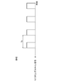
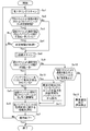
- FIG. 4 It is a schematic diagram showing an electric storage system concerning this embodiment, and a device connected to an electric storage system. It is a block diagram which shows the structure of the electrical storage system shown in FIG. It is a flowchart which shows the flow of control in the control unit immediately after starting of the electrical storage system which concerns on this embodiment, or immediately after restarting. It is a sequence diagram which shows the flow of the recognition scan shown in FIG. 4 is a timing chart showing a transmission timing of a recognition scan signal transmitted from the control unit to each battery unit in the recognition scan shown in FIG. 3. It is a flow chart which shows the flow of control in the control unit under operation of the electric storage system concerning this embodiment. It is a sequence diagram which shows the flow of the monitoring scan shown in FIG.
- FIG. 6 is a timing chart showing the transmission timing of a monitoring scan signal transmitted from the control unit to each battery unit in the monitoring scan shown in FIG. 5. It is a flowchart which shows the flow of control in the control unit in operation of the electrical storage system which concerns on an application example.
- FIG. 1 is a schematic diagram showing a power storage system 1 according to the present embodiment and devices connected to the power storage system 1.
- the power storage system 1 shown in FIG. 1 supplies power to an external device DD connected via a power line PL1 when an emergency situation such as a power failure occurs.
- power storage system 1 stores electric power supplied from external power supply PP connected via power line PL2.
- the external device DD connected to the power storage system 1 according to the present embodiment is, for example, a communication device, lighting, various facilities, and an office device for BCP.
- the power storage system 1 according to the present embodiment can change the capacity of storable power according to the external device DD connected via the power line PL1.
- the external power supply PP connected to the power storage system 1 according to the present embodiment is an electric power source that supplies AC power or DC power, and includes, for example, a commercial AC power supply and a solar cell unit.
- the power lines PL1 and PL2 in this embodiment are, for example, power cables designed, developed, and produced according to a predetermined standard.
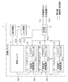
- FIG. 2 is a block diagram showing a configuration of power storage system 1 shown in FIG.
- the power storage system 1 shown in FIG. 2 includes a plurality of battery units 21 to 2n (n: integer), a charging / discharging unit 5, a control unit 6, an input device 7, and a notification device 8.
- a plurality of battery units 21 to 2n are connected via a communication line (control line) CL1.
- a communication line CL1 in order not to complicate the circuit configuration of the electricity storage system 1, a plurality of battery units 21 to 2n are connected by a communication line CL1 in a daisy chain and various signals transmitted from a control unit 6 described later. It shows a configuration capable of receiving at the same time.
- the plurality of battery units 21 to 2n may be connected in series or in parallel via the communication line (control line) CL1. Further, the plurality of battery units 21 to 2n are connected in parallel via the power line PL3. For example, the number of mounted battery units 21 to 2n can be changed.
- the communication line CL1 in the present embodiment is, for example, a communication optical cable designed, developed, and produced according to a predetermined standard, or a communication electric cable.
- the battery units 21 to 2n are considered.
- the control unit 6 may be connected to each other by a plurality of communication lines to form a redundant configuration.
- the plurality of battery units 21 to 2n include battery modules 31 to 3n (n: integer) and charge / discharge control circuits 41 to 4n (n: integer).
- n integer
- charge / discharge control circuits 41 to 4n integer
- the battery module 31 and the charge / discharge control circuit 41 will be described. Only the battery modules 32 to 3n and the charge / discharge control circuits 42 to 4n will be described in detail.
- the battery module 31 stores electric power to be supplied to the external device DD.
- the battery module 31 is connected to the external device DD via the power line PL3, the charging / discharging unit 5, and the power line PL1.
- the battery module 31 supplies the accumulated power to the external device DD under the control of the charge / discharge control circuit 41.
- the battery module 31 is connected to the external power source PP via the power line PL3, the charging / discharging unit 5, and the power line PL2.
- the battery module 31 stores the electric power supplied from the external power source PP.
- the power line PL3 in the present embodiment is, for example, a power cable designed, developed, and produced according to a predetermined standard.
- the charge / discharge control circuit 41 is connected to the battery module 31 via an electric wire ICL1 such as a power line, a thermocouple, or a voltage take-in line.
- the charge / discharge control circuit 41 controls the charge / discharge operation of the battery module 31 under the control of the control unit 6. For example, the charge / discharge control circuit 41 instructs the battery module 31 to supply power to the external device DD. When accumulating the electric power supplied from the external power supply PP, the charge / discharge control circuit 41 instructs the battery module 31 to accumulate the electric power supplied from the external power supply PP.
- the charge / discharge control circuit 41 collects and collects information on the state of the battery module 31 (hereinafter, referred to as state information of the battery module 31) in response to a request from the control unit 6.
- state information of the battery module 31 is transmitted to the control unit 6.
- the charge / discharge control circuit 41 collects information on the temperature, voltage, and current of the battery module 31 from the battery module 31 provided with a temperature sensor, a voltage sensor, and a current sensor (not shown).
- the charge / discharge control circuit 41 transmits the collected information about the temperature, voltage, and current of the battery module 31 to the control unit 6.
- the charge / discharge unit 5 is connected to the control unit 6 via the communication line (control line) CL2.
- the charge / discharge unit 5 includes a plurality of switching elements composed of electronic components such as field effect transistors or bipolar transistors.
- the charging / discharging unit 5 executes a discharging process and a charging process under the control of the control unit 6.
- the charging / discharging unit 5 receives the electric power output from each of the battery modules 31 to 3n via the electric power line PL3, and the received electric power can be used in the external device DD as desired DC power or AC power. Convert to.
- the charge / discharge unit 5 supplies the converted desired DC power or AC power to the external device DD via the power line PL1.
- the charging / discharging unit 5 converts the DC power or AC power output from the external power source PP via the power line PL2 into desired DC power that can be stored in the battery module 31.
- the charging / discharging unit 5 supplies the converted DC power to the battery modules 31 to 3n via the power line PL3.
- the charging / discharging unit 5 can also directly supply the output power of the external power source PP to the external device DD without passing through the battery modules 31 to 3n.
- the communication line CL2 in this embodiment is, for example, an electric wire, an electric circuit, or an electric cable designed, developed, and produced according to a predetermined standard.
- the control unit 6 has a predetermined processor as a hardware resource.
- the control unit 6 is connected to the plurality of battery units 21 to 2n via the communication line CL1.
- the control unit 6 is connected to the battery unit 21 via the communication line CL1.
- the control unit 6 may be connected to each of the plurality of battery units 21 to 2n via the communication line CL1.
- the control unit 6 in the present embodiment monitors the states of the battery modules 31 to 3n while controlling the operations of the charge and discharge control circuits 41 to 4n.
- control unit 6 transmits a recognition scan signal for confirming the connection state to each of the plurality of battery units 21 to 2n immediately after the power storage system 1 is started or immediately after the power storage system 1 is restarted.
- the control unit 6 executes the first establishing process for establishing communication with each of the plurality of battery units 21 to 2n.
- control unit 6 performs a monitoring scan for acquiring information regarding the states of the battery modules 31 to 3n with respect to the battery units 21 to 2n for which communication has been established by the first establishing process.
- control unit 6 executes the first monitoring process for monitoring the states of the battery modules 31-3n included in each of the plurality of battery units 21-2n whose communication has been established by the first establishing process.
- control unit 6 controls the plurality of battery units 21 to 2n after the execution of the first monitoring process, when a predetermined condition related to the presence or absence of reception of a response signal or a notification signal described later is satisfied. Then, the recognition scan signal is retransmitted, and the response signal transmitted from the battery units 21 to 2n receiving the recognition scan signal is received. As a result, the control unit 6 executes the second establishment process for reestablishing communication with each of the plurality of battery units 21 to 2n.
- the predetermined condition is, for example, when there is a battery unit that cannot receive the notification signal among the battery units 21 to 2n whose communication is established by the first establishing process in the first monitoring process, or In the case where the number of the battery units 21 to 2n with which communication is established by the first establishing process does not match the predetermined number required for operation of the power storage system 1, the second establishing process is periodically executed. This is the case where a predetermined time as a reference for has elapsed.
- control unit 6 retransmits the monitoring scan signal to the battery units 21 to 2n whose communication has been reestablished by the second establishing process after executing the second establishing process, and receives the monitoring scan signal from the battery unit 21-2n.
- the notification signals transmitted from the units 21 to 2n are received.
- the control unit 6 executes the second monitoring process of monitoring the states of the battery modules 31 to 3n included in each of the plurality of battery units 21 to 2n whose communication has been reestablished by the second establishing process. Note that a specific control flow in the control unit 6 will be described later in detail with reference to the drawings.
- the input device 7 is connected to the control unit 6 via the communication line (control line) CL3.
- the input device 7 converts an input operation of a user who maintains and manages the power storage system 1 into an electric signal and outputs the electric signal to the control unit 6.
- a user uses the input device 7 in the present embodiment, a user performs an operation such as a system start operation and a system stop operation.
- the input device 7 according to the present embodiment has a mouse, a keyboard, a trackball, a switch button, a touch pad that performs an input operation by touching an operation surface, a touch pen that performs handwriting input, and a display screen and a touch pad that are integrated. At least one of the touch panel displays.
- the communication line CL3 in the present embodiment is, for example, an electric wire, an electric circuit, or an electric cable designed, developed, and produced according to a predetermined standard.
- the notification device 8 is connected to the control unit 6 via the communication line (control line) CL4. Under the control of the control unit 6, the notification device 8 notifies the monitoring result of each of the plurality of battery units 21 to 2n.
- the monitoring result includes at least state information of the battery modules 31 to 3n included in each of the plurality of battery units 21 to 2n.
- the notification device 8 in the present embodiment is an optical device such as an LED, an audio device such as a speaker, or a CRT display (Cathode Ray Tube Display), a liquid crystal display (LCD: Liquid Crystal Display), an organic EL display (OELD: Organic Electro Luminescence). Display) or a display device such as a plasma display.
- the communication line CL4 in this embodiment is, for example, an electric wire, an electric circuit, or an electric cable designed, developed, and produced according to a predetermined standard.
- the power storage system 1 is provided with five battery units 21 to 25.
- the number of battery units (predetermined number) required to operate the system connected to the power storage system 1 is 5, and the number of battery units that are actually operated (in other words, supply power to the external device DD at the same time) And the remaining battery units are for backup.
- the number of battery units (minimum number) required for the operation of the external device DD is three. That is, in the power storage system 1 according to the present embodiment, if communication with at least three battery units is established, the system can be operated. Further, the predetermined number is the number of battery units required in the system considering redundancy.
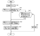
- FIG. 3 is a flowchart showing a control flow in the control unit 6 immediately after the power storage system 1 according to the present embodiment is started or immediately after being restarted.
- step Sa1 the control unit 6 executes a recognition scan (first establishing process).
- the recognition scan (first establishing process) is a battery unit capable of supplying power to the external device DD by confirming the connection state with each of the plurality of battery units 21 to 25 to be controlled in the control unit 6.
- This is a process for recognizing 21 to 25.
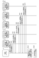
- FIG. 4 is a sequence diagram showing a flow of the recognition scan shown in FIG.
- FIG. 5 is a timing chart showing the transmission timing of the recognition scan signal transmitted from the control unit 6 to each of the battery units 21 to 25 in the recognition scan shown in FIG.
- control unit 6 sequentially transmits a recognition scan signal for confirming the connection state with each of the battery units 21 to 25 to the battery units 21 to 25 at predetermined time intervals via the communication line CL1. .. Further, the control unit 6 receives a response signal to the recognition scan signal, which is transmitted from the battery units 21 to 25 that have received the recognition scan signal.
- step Sb1 the control unit 6 sends a recognition scan signal to the battery unit 21. Further, in step Sb2, the control unit 6 receives a response signal to the recognition scan signal generated and transmitted by the charge / discharge control circuit 41 included in the battery unit 21 that has received the recognition scan signal.
- the response signal transmitted from the charge / discharge control circuit 41 includes the identification information of the battery unit 21 (for example, identification ID: 1).
- step Sb3 the control unit 6 transmits a recognition scan signal to the battery unit 22. Further, in step Sb4, the control unit 6 receives a response signal to the recognition scan signal generated and transmitted by the charge / discharge control circuit 42 included in the battery unit 22 that has received the recognition scan signal.
- the response signal transmitted from the charge / discharge control circuit 42 includes identification information of the battery unit 22 (for example, identification ID: 2).
- step Sb5 the control unit 6 sends a recognition scan signal to the battery unit 23. Further, in step Sb6, the control unit 6 receives a response signal to the recognition scan signal generated and transmitted by the charge / discharge control circuit 43 included in the battery unit 23 that has received the recognition scan signal.
- the response signal transmitted from the charge / discharge control circuit 43 includes the identification information (for example, identification ID: 3) of the battery unit 23.
- step Sb7 the control unit 6 sends a recognition scan signal to the battery unit 24. Further, in step Sb8, the control unit 6 receives a response signal to the recognition scan signal generated and transmitted by the charge / discharge control circuit 44 included in the battery unit 24 that has received the recognition scan signal.
- the response signal transmitted from the charge / discharge control circuit 44 includes identification information (for example, identification ID: 4) of the battery unit 24.
- step Sb9 the control unit 6 sends a recognition scan signal to the battery unit 25. Furthermore, in step Sb10, the control unit 6 receives a response signal to the recognition scan signal generated and transmitted by the charge / discharge control circuit 45 included in the battery unit 25 that has received the recognition scan signal.
- the response signal transmitted from the charge / discharge control circuit 45 includes the identification information of the battery unit 25 (for example, identification ID: 5).
- the recognition scan signal transmitted immediately after the power storage system 1 is started or immediately restarted is transmitted to each of the battery units 21 to 25 at the time interval Ta shown in FIG.
- the time interval Ta is, for example, a time interval set so that a communication failure and a response delay do not occur between the control unit 6 and the battery units 21 to 25.
- the predetermined time is a time-out time for forcibly ending the recognition scan, and is sufficiently longer than the time interval Ta.
- the predetermined time is appropriately set according to the design of the power storage system 1.
- step Sb11 the control unit 6 identifies the battery units 21 to 25 that transmitted the response signal based on the identification information of each of the battery units 21 to 25 included in the received response signal. Further, in step Sb12, the control unit 6 recognizes the specified battery units 21 to 25 as the battery units 21 to 25, which can establish communication with the control unit 6 and can supply power to the external device DD. Specifically, since the control unit 6 includes the identification IDs of all the battery units 21 to 25 in the received response signal, the communication between the battery units 21 to 25 and the control unit 6 is established, and the external device DD Recognize as a battery unit that can supply power to
- step Sa2 the control unit 6 controls the battery units 21 to 25 that can supply power to the external device DD, the communication of which is established by the recognition scan (first establishing process). It is determined whether or not the number matches the number (predetermined number) of the battery units 21 to 25 necessary for operating the power storage system 1.
- the control unit 6 supplies power to the external device DD in step Sa3. The operation of the power storage system 1 is started using the battery units 21 to 25 that can be supplied. Further, in step Sa4, the control unit 6 notifies the information regarding the availability of the battery units 21 to 25.
- the number of the battery units 21 to 25, which the control unit 6 has recognized and whose communication has been established by the recognition scan (first establishing process), is five.
- the predetermined number is five. That is, in the control unit 6, since the number of the battery units 21 to 25, the communication of which is established by the recognition scan (first establishing process), matches the predetermined number, the communication is established by the recognition scan (first establishing process). The operation of the power storage system 1 is started using the battery units 21 to 25. In the subsequent process, when the number of battery units 21 to 25 with which communication is established matches the predetermined number, the control unit 6 does not execute the recognition scan (second establishing process) in principle.
- the control unit 6 causes the recognition scan (second establishment). Process). Further, the control unit 6 controls the operations of the charge / discharge control circuits 41 to 45 included in the battery units 21 to 25 with which communication has been established by the recognition scan (first establishing process). Further, the control unit 6 controls the notification device 8 to notify that the battery units 21 to 25 are usable.
- step Sa5 determines the recognition scan (step Sa5) in step Sa5. It is determined whether or not the number of battery units 21 to 25 with which communication is established by the first establishing process) is equal to or larger than the number (minimum number) of battery units required for the operation of the external device DD.
- step Sa3 the control unit 6 starts the operation of the power storage system 1 by using the battery units 21 to 25 whose communication has been established by the recognition scan (first establishing process).
- the recognition scan (second establishing process) is periodically executed. Further, in step Sa4, the control unit 6 notifies the information regarding the availability of the battery units 21 to 25.
- step Sa5 when the number of battery units 21 to 25 with which communication is established by the recognition scan (first establishing process) is less than the minimum number (that is, the number of battery units 21 to 25 that can supply power is less than 3).
- step Sa6 control unit 6 notifies that abnormality has been detected in power storage system 1. Specifically, if the number of the battery units 21 to 25 that have transmitted the response signal to the recognition scan signal is less than the minimum number required for the operation of the external device DD even if the predetermined time has elapsed, the external device DD is operated. This means that the required number of battery units 21 to 25 is insufficient. Therefore, the control unit 6 controls the notification device 8 to notify the user that the operation of the power storage system 1 cannot be started. As a result, the power storage system 1 according to the present embodiment can prompt the user to perform the inspection and recovery work of the power storage system 1 immediately after the system is started or immediately after being restarted.
- FIG. 6 is a flowchart showing a control flow in the control unit 6 during operation of the power storage system 1 according to this embodiment.
- the control unit 6 executes a monitoring scan (first monitoring process) during operation of the system.
- the monitoring scan (first monitoring process) is a battery unit recognized by the control unit 6 as a battery unit capable of supplying power to the external device DD whose communication is established by the recognition scan (first establishing process).
- This is a process for acquiring the state information of the battery modules 31 to 35 included in 21 to 25.
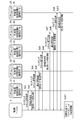
- FIG. 7 is a sequence diagram showing the flow of the monitoring scan shown in FIG.
- FIG. 8 is a timing chart showing the transmission timing of the monitoring scan signal transmitted from the control unit 6 to each of the battery units 21 to 25 in the monitoring scan shown in FIG.
- the control unit 6 detects the battery units 21 to 25 included in the battery units 21 to 25 from the battery units 21 to 25 recognized as the battery units capable of supplying the electric power to the external device DD via the communication line CL1.
- a monitoring scan signal for acquiring status information is sequentially transmitted at predetermined time intervals. Further, the control unit 6 receives a notification signal for the monitoring scan signal, which is transmitted from the battery units 21 to 25 that have received the monitoring scan signal.
- step Sd1 the control unit 6 sends a monitoring scan signal to the battery unit 21. Further, in step Sd2, the control unit 6 receives the notification signal generated and transmitted by the charge / discharge control circuit 41 included in the battery unit 21 that has received the monitoring scan signal.
- the notification signal transmitted from the charge / discharge control circuit 41 includes the identification information of the battery unit 21 (for example, identification ID: 1) and the state information of the battery module 31 included in the battery unit 21 (for example, the temperature of the battery module 31). , Voltage, and current information).
- step Sd3 the control unit 6 transmits a monitoring scan signal to the battery unit 22. Further, in step Sd4, the control unit 6 receives the notification signal generated and transmitted by the charge / discharge control circuit 42 included in the battery unit 22 that has received the monitoring scan signal.
- the notification signal transmitted from the charge / discharge control circuit 42 includes the identification information of the battery unit 22 (for example, identification ID: 2) and the state information of the battery module 32 included in the battery unit 22 (for example, the temperature of the battery module 32). , Voltage, and current information).
- step Sd5 the control unit 6 sends a monitoring scan signal to the battery unit 23. Further, in step Sb6, the control unit 6 receives the notification signal generated and transmitted by the charge / discharge control circuit 43 included in the battery unit 23 that has received the monitoring scan signal.
- the notification signal transmitted from the charge / discharge control circuit 43 includes the identification information of the battery unit 23 (for example, identification ID: 3) and the state information of the battery module 33 included in the battery unit 23 (for example, the temperature of the battery module 33). , Voltage, and current information).
- step Sd7 the control unit 6 sends a monitoring scan signal to the battery unit 24. Further, in step Sd8, the control unit 6 receives the notification signal generated and transmitted by the charge / discharge control circuit 44 included in the battery unit 24 that has received the monitoring scan signal.
- the notification signal transmitted from the charge / discharge control circuit 44 includes the identification information of the battery unit 24 (for example, identification ID: 4) and the state information of the battery module 34 included in the battery unit 24 (for example, the temperature of the battery module 34). , Voltage, and current information).
- step Sd9 the control unit 6 sends a monitoring scan signal to the battery unit 25. Further, in step Sd10, the control unit 6 receives the notification signal generated and transmitted by the charge / discharge control circuit 45 included in the battery unit 25 that has received the monitoring scan signal.
- the notification signal transmitted from the charge / discharge control circuit 45 includes the identification information of the battery unit 25 (for example, identification ID: 5) and the state information of the battery module 35 included in the battery unit 25 (for example, the temperature of the battery module 35). , Voltage, and current information).
- the monitoring scan signal is transmitted to each battery unit 21-25 at the time interval Tb shown in FIG.
- the time interval Tb is longer than the time interval Ta shown in FIG. Similar to the time interval Ta, the time interval Tb is a time interval set so that a communication failure and a response delay do not occur between the control unit 6 and the battery units 21 to 25.
- the time interval Tb is a time interval set so that a communication failure and a response delay do not occur between the control unit 6 and the battery units 21 to 25.
- the monitoring scan is interrupted and recognized. Perform a scan. Then, the monitoring scan for the recognized battery unit is started.
- the predetermined time is a time-out time for forcibly ending the monitoring scan, and is sufficiently longer than the time interval Tb. The predetermined time is appropriately set according to the design of the power storage system 1.
- step Sd11 the control unit 6 monitors the states of the battery modules 31 to 35 based on the state information of the battery modules 31 to 35 included in the received response signal. Specifically, the control unit 6 determines whether or not the battery modules 31 to 35 are abnormal and fully charged based on the information on the temperatures of the battery modules 31 to 35. In addition, the control unit 6 determines whether or not a malfunction or failure has occurred between the battery modules 31 to 35, the battery modules 31 to 35, and the external device DD based on the information about the voltages and currents of the battery modules 31 to 35. To determine.
- step Sc2 After the completion of the monitoring scan (first monitoring process), in step Sc2, has the control unit 6 received the above status information from all the battery units 21 to 25 with which communication has been established by the recognition scan (first establishing process)? Determine whether or not.
- the control unit 6 determines that the number of battery units with which communication has been established by the recognition scan (first establishing process). It is determined whether the number does not match the predetermined number.
- step Sc4 the control unit 6 determines whether the predetermined time has elapsed. Determine whether or not.
- the predetermined time is a reference time for periodically executing the recognition scan (second establishing process) during the operation of the power storage system 1. Note that the predetermined time may be set to be sufficiently long so that the cycle of performing the recognition scan (second establishing process) is sufficiently long as compared with the cycle of performing the monitoring scan.
- the control unit 6 in the present embodiment when the number of battery units with which communication has been established by the recognition scan (first establishing process) matches the predetermined number (No in step Sc3), or the recognition scan (first establishing process). If the number of battery units with which communication has been established does not match the predetermined number (Yes in step Sc3) and the predetermined time has not elapsed (No in step Sc4), in step Sc5, the control unit 6 continues the operation of the power storage system 1 by using the battery units 21 to 25 whose communication has been established by the recognition scan (first establishing process). Further, in step Sc6, the control unit 6 notifies the information regarding availability of the battery units 21 to 25. In other words, the control unit 6 does not execute the recognition scan at the predetermined time interval when the communication with the predetermined number of battery units can be established by the recognition scan.
- step Sc7 the control unit 6 determines whether to end the operation of the power storage system 1. When ending the operation of the power storage system 1 (Yes in step Sc7), the control unit 6 ends the process. When the operation of the power storage system 1 is continued (No in step Sc7), the process returns to step Sc1.
- the control unit 6 executes a recognition scan (second establishing process). Specifically, in the monitoring scan (first monitoring process), the control unit 6 determines that the battery unit 21 to 25, of which the communication is established by the recognition scan (first establishing process), cannot receive the notification signal. If there is, a recognition scan (second establishing process) is executed.
- the recognition scan (second establishment process) executed in step Sc8 when Step Sc2 is No communication is established by the recognition scan (first establishment process), and communication is performed during operation of the power storage system 1. This is executed in order to eliminate a response waiting time longer than usual, which occurs due to the monitoring scan (second monitoring process) for the disconnected battery unit.
- the control unit 6 in the present embodiment operates the power storage system 1 by using the battery unit that newly establishes communication by the recognition scan (second establishing process) executed in step Sc8 when step Sc2 is No. Carry out.
- control unit 6 in the present embodiment does not communicate with the battery unit whose communication has been established by the recognition scan (first establishing process) and which has been disconnected during the operation of the power storage system 1, and therefore the control unit 6 It is possible to eliminate a longer response waiting time than usual which occurs in the battery unit whose communication with 6 is disconnected.
- step Sc8 the control unit 6 executes a recognition scan (second establishing process).
- the recognition scan (second establishing process) executed in step Sc8 when step Sc4 is Yes is periodically executed during the operation of the power storage system 1.
- the control unit 6 determines that the number of battery units for which communication has been established by the recognition scan (first establishing process) does not match the predetermined number, and the predetermined time has elapsed ( Yes in step Sc4), the recognition scan (second establishing process) is periodically executed to try to establish communication with the battery unit in which communication is not established.
- the recognition scan (the second establishment) is periodically performed. (Processing), the communication between the control unit 6 and the battery units 21 to 25, which has not been established at the start of the operation of the power storage system 1, can be established during the operation of the power storage system 1.
- the control unit 6 does not execute the recognition scan (second establishing process) in principle.
- the control unit 6 causes the recognition scan (second establishment). Process).
- step Sc9 the control unit 6 determines whether or not the number of the battery units 21 to 25 with which communication is established by the recognition scan (second establishing process) matches a predetermined number. To judge. When the number of the battery units 21 to 25 with which communication has been established by the recognition scan (second establishment process) matches the predetermined number (Yes in step Sc9), the control unit 6 determines the recognition scan (second establishment process) in step Sc5. The operation of the power storage system 1 is continued by using the battery units 21 to 25, the communication of which is established by the process). Further, in step Sc6, the control unit 6 notifies the information regarding availability of the battery units 21 to 25. In the present embodiment, the control unit 6 controls the notification device 8 to notify the user that the battery units 21 to 25 can be used.
- the control unit 6 determines in step Sc10 the recognition scan ( It is determined whether or not the number of battery units 21 to 25 with which communication has been established by the second establishing process) is at least the minimum number. If the number of battery units 21 to 25 with which communication is established by the recognition scan (second establishing process) is at least the minimum number (that is, the number of battery units 21 to 25 that can supply power to the external device DD is three or more).
- step Sc5 the control unit 6 continues the operation of the power storage system 1 by using the battery units 21 to 25 with which communication has been established by the recognition scan (second establishing process). .. That is, when the operation of the power storage system 1 is continued (No in Step Sc7), the control unit 6 returns to Step Sc1 and executes the monitoring scan (second monitoring process). In addition, the control unit 6 re-establishes communication with each of the plurality of battery units 21 to 25 when a predetermined condition related to the presence or absence of reception of the response signal or the notification signal is satisfied (second scan). Establishing process) is executed.
- control unit 6 continues to execute the recognition scan (second establishing process) for re-establishing communication with each of the plurality of battery units 21 to 25 as long as the above-described predetermined condition is satisfied. Further, in step Sc6, the control unit 6 notifies the information regarding availability of the battery units 21 to 25.
- the control unit 6 notifies in step Sc11 that an abnormality has been detected in the power storage system 1. Specifically, if the number of the battery units 21 to 25 that have transmitted the response signal to the recognition scan signal is less than the minimum number required for the operation of the external device DD even if the predetermined time has elapsed, the external device DD is operated. This means that the required number of battery units 21 to 25 is insufficient.
- control unit 6 controls the notification device 8 to notify the user that the operation of the power storage system 1 cannot be continued. Further, the control unit 6 stops the operation of the power storage system 1 because it cannot continue the operation. As a result, the power storage system 1 according to the present embodiment can prompt the user to perform inspection and restoration work of the power storage system 1 during operation of the system.
- control unit 6 of the power storage system 1 establishes communication with the control unit 6 because communication is established by the establishment process and communication with the battery units 21 to 2n for which communication is not established is performed. It is possible to eliminate a longer than usual response waiting time that occurs in the battery units 21 to 2n for which communication is not established.
- control unit 6 of the power storage system 1 determines that the number of the battery units 21 to 2n that have transmitted the response signal to the recognition scan signal during the recognition scan execution process does not affect the system operation.
- the control unit 6 of the power storage system 1 controls the notification device 8 to notify the user that the power storage system 1 cannot be operated.
- the power storage system 1 according to the present embodiment can prompt the user to perform inspection and restoration work of the power storage system.
- control unit 6 of the power storage system 1 starts the operation of the system when the number of the battery units 21 to 2n whose communication has been established by the establishment process is equal to the predetermined number
- the system can be operated as usual.
- control unit 6 of the power storage system 1 according to the present embodiment executes the establishing process again even when the communication between the control unit 6 and the battery units 21 to 2n is disconnected during the operation of the system.
- it is possible to establish communication between the control unit 6 and the battery units 21 to 2n during operation of the system.
- control unit 6 of the power storage system 1 starts the operation of the system in a state where the number of the battery units 21 to 2n for which communication is established by the establishment process does not match the predetermined number.
- the communication between the control unit 6 and the battery units 21 to 2n can be established during the operation of the system by executing the establishing process again after the elapse of the predetermined time.
- the power storage system 1 can realize smoother system operation.
- the power storage system 1 recognizes the battery units 21 to 2n for which communication with the control unit 6 is established as the battery units 21 to 2n capable of supplying power to the external device DD.
- the power line PL1 between the battery modules 31 to 3n included in the battery units 21 to 2n, the battery modules 31 to 3n, the external device DD, and the external power source PP. , PL2, PL3, and charging / discharging unit 5 have malfunctions and failures, and there may be battery units 21 to 2n that cannot supply power to the external device DD.
- control unit 6 of the power storage system 1 between the battery modules 31 to 3n included in the battery units 21 to 2n and the battery modules 31 to 3n, the external device DD, and the external power source PP during operation of the system.
- the control is performed in consideration of the troubles and failures that occur in the power lines PL1, PL2, PL3 and the charging / discharging unit 5 provided in the.
- FIG. 9 is a flowchart showing a control flow in the control unit 6 during operation of the power storage system 1 according to the application example. It should be noted that detailed description of the portions overlapping with those of FIG. 6 will be omitted and will be appropriately described as necessary.
- step Se9 the control unit 6 determines whether or not the number of the battery units 21 to 2n for which communication has been established by the recognition scan (second establishing process) matches a predetermined number.
- the control unit 6 sets the battery modules 31 to 2n in step Se10. It is determined whether or not an abnormality is detected in 3n.
- the temperature of the battery modules 31 to 3n detected by a temperature sensor is high, an abnormality may occur in the battery modules 31 to 3n and the battery modules 31 to 3n may be damaged.
- the voltage and current of the battery modules 31 to 3n are not detected by a voltage sensor and a current sensor (not shown), they are provided between the battery modules 31 to 3n, the battery modules 31 to 3n, the external device DD, and the external power source PP.
- the power lines PL1, PL2, PL3 and the charging / discharging unit 5 that are generated have troubles or failures.
- the control unit 6 supplies power to the external device DD in step Se11 from the battery units 21 to 2n in which the abnormality is detected. Exclude from the battery unit that can be supplied.
- step Se10 If no abnormality is detected in the battery modules 31 to 3n (No in step Se10), the control unit 6 uses the battery units 21 to 2n capable of supplying electric power to the external device DD in step Se5. The operation of the power storage system 1 is continued. After that, the processing of steps Se12 and Se13 in the application example is the same as the processing of steps Sc10 and Sc11 shown in FIG.
- the control unit 6 of the power storage system 1 is provided between the battery modules 31 to 3n, the battery modules 31 to 3n, the external device DD, and the external power source PP during the operation of the system.
- the control is executed in consideration of the problems and failures that occur in the power lines PL1, PL2, PL3 and the charging / discharging unit 5 that are generated.
- the control unit 6 excludes the battery units 21 to 2n in which the abnormality is detected from the battery units that can supply power to the external device DD. ..
- the power storage system 1 according to the application example is provided between the battery modules 31 to 3n, the battery modules 31 to 3n, the external device DD, and the external power source PP even if the communication with the control unit 6 is established. It is possible to eliminate unnecessary communication with the battery units 21 to 2n in which the power lines PL1, PL2, PL3 and the charging / discharging unit 5 have malfunctions or failures. As a result, the control unit 6 of the power storage system 1 according to the application example can reduce the time required for control of the entire power storage system 1. Thus, the power storage system 1 according to the application example can realize smoother system operation.
- the power storage system 1 according to the present embodiment is not limited to this.
- battery units designed, developed, and produced according to different standards may be applied to the power storage system 1.
- predetermined processor used in the above description is, for example, a dedicated or general-purpose processor such as a CPU (Central Processing Unit) and an MPU (Micro Processing Unit), or an application-specific integrated circuit (ASIC: Application). Specific Integrated Circuit), programmable logic device (for example, simple programmable logic device (SPLD: Simple Programmable Logic Device), complex programmable logic device (CPLD: Complex Programmable Logic Device), and field programmable gate array (FPGA: Field Programmable Gate Array) Further, each component (each processing unit) of the present embodiment is not limited to a single processor, and may be realized by a plurality of processors. Processing unit) You may make it implement
- SPLD Simple Programmable Logic Device
- CPLD Complex Programmable Logic Device
- FPGA Field Programmable Gate Array
Landscapes
- Engineering & Computer Science (AREA)
- Power Engineering (AREA)
- Manufacturing & Machinery (AREA)
- Chemical & Material Sciences (AREA)
- Chemical Kinetics & Catalysis (AREA)
- Electrochemistry (AREA)
- General Chemical & Material Sciences (AREA)
- Charge And Discharge Circuits For Batteries Or The Like (AREA)
- Secondary Cells (AREA)
- Protection Of Static Devices (AREA)
- Remote Monitoring And Control Of Power-Distribution Networks (AREA)
Abstract
制御ユニット(6)は、第1監視処理の実行後、制御ユニットにおける応答信号、又は通知信号の受信の有無に関連する所定の条件に合致した場合に、複数のバッテリユニット(21~2n)各々に対して認識スキャン信号を再送信し、認識スキャン信号を受信したバッテリユニットから送信された応答信号を受信することで、複数のバッテリユニット各々との通信を再度確立する第2確立処理を実行し、第2確立処理の実行後、第2確立処理により通信が再度確立されたバッテリユニットに含まれるバッテリモジュール(31~3n)の状態を監視する第2監視処理を実行する。
Description
本発明は、外部機器に電力を供給する蓄電システム及び蓄電システムの制御方法に関する。
例えば、下記特許文献1に開示されるように、外部機器に電力を供給する蓄電システムがある。上記蓄電システムは、電力を蓄積する複数の電池ユニット、並びに上記複数の電池ユニットを監視及び制御する電池管理部を備える。蓄電システムは、各電池ユニット、並びに電池管理部及び電池ユニットの間で生じる不具合及び障害を監視しつつ、外部機器に電力を供給している。なお、上記蓄電システムでは、各電池ユニットに順次コマンド信号を送信して、上記コマンド信号に対する応答として各電池ユニットから受信した各電池ユニットの状態に関する情報に基づいて、各電池ユニットの状態を監視している。
上記蓄電システムでは、システムの運用中に上記電池管理部及び電池ユニットの間の通信が切断される場合がある。例えば、電池管理部及び各電池ユニットを接続する通信線の断線、又は電池ユニットにおける不具合及び障害により通信が切断される場合、ノイズ等の一時的な通信異常が発生することにより通信が切断される場合、偶発的な異常対策に対する冗長運転やスケジュール運転(メンテナンスを含む)等で通信が切断される場合が挙げられる。上記電池管理部及び電池ユニットの間の通信が切断された場合、通信が切断された電池ユニットの動作を制御することができず、外部機器に電力を供給することができない。このため、上記電池管理部及び電池ユニットの間の通信を再度確立する復旧作業を行って、電池管理部との通信が切断された電池ユニットをシステムに復帰させている。
ところで、上記蓄電システムにおいて、システムの運用中に電池管理部及び電池ユニットの間の通信が切断された場合、一定の時間間隔で各電池ユニットの状態に関する情報を取得することができず、イレギュラーなタイミングで各電池ユニットの状態に関する情報を取得する場合がある。例えば、蓄電システムでは、上記コマンド信号を電池ユニットに送信した後、所定時間内に上記コマンド信号に対する応答を受信するまで次の処理へ移行しないようにしている。すなわち、蓄電システムでは、各電池ユニットの状態に関する情報を取得する工程において、応答待ち時間が発生する。もし、システムの運用中に電池管理部及び電池ユニットの間の通信が切断された場合、所定時間内に上記コマンド信号に対する応答を受信することができないため、通常より長い応答待ち時間が発生する。また、蓄電システムにおいて各電池ユニットの状態を監視するごとに、電池管理部との通信が切断された電池ユニットにおいて通常より長い応答待ち時間が発生するため、次に取得する電池ユニットの状態に関する情報の取得タイミングが遅延する。すなわち、上記蓄電システムにおいて、システムの運用中に電池管理部及び電池ユニットの間の通信が切断された場合、一定の時間間隔で各電池ユニットの状態に関する情報を取得することができないという問題がある。
本発明はこのような事情を考慮してなされたものであり、その目的とするところは、より円滑なシステム運用を実現することができる蓄電システムの制御方法、及び蓄電システムを提供することにある。
本発明は前述の課題の少なくとも一部を解決するためになされたものであり、以下の態様として実現することができる。
本発明の態様に係る蓄電システムの制御方法は、外部機器へ供給するための電力を蓄積するバッテリモジュール、及び前記バッテリモジュールの充放電動作を制御する充放電制御回路を含む複数のバッテリユニットと、前記充放電制御回路各々の動作を制御しつつ、前記バッテリモジュール各々の状態を監視する制御ユニットと、を具備する蓄電システムの制御方法において、前記制御ユニットは、前記蓄電システムの起動直後、又は再起動直後に、前記複数のバッテリユニット各々に対して接続状態を確認するための認識スキャン信号を送信し、前記認識スキャン信号を受信した前記バッテリユニットから送信された前記認識スキャン信号に対する応答信号を受信することで、前記複数のバッテリユニット各々との通信を確立する第1確立処理を実行し、前記第1確立処理の実行後、前記第1確立処理により通信が確立された前記バッテリユニットに対して前記バッテリモジュールの状態に関する情報を取得するためのモニタリングスキャン信号を送信し、前記モニタリングスキャン信号を受信した前記バッテリユニットから送信された前記モニタリングスキャン信号に対する通知信号を受信することで、前記第1確立処理により通信が確立された前記バッテリユニットに含まれる前記バッテリモジュールの状態を監視する第1監視処理を実行し、前記第1監視処理の実行後、前記制御ユニットにおける前記応答信号、又は前記通知信号の受信の有無に関連する所定の条件に合致した場合に、前記複数のバッテリユニット各々に対して前記認識スキャン信号を再送信し、前記認識スキャン信号を受信した前記バッテリユニットから送信された前記応答信号を受信することで、前記複数のバッテリユニット各々との通信を再度確立する第2確立処理を実行し、前記第2確立処理の実行後、前記第2確立処理により通信が再度確立された前記バッテリユニットに対して前記モニタリングスキャン信号を再送信し、前記モニタリングスキャン信号を受信した前記バッテリユニットから送信された前記通知信号を受信することで、前記第2確立処理により通信が再度確立された前記バッテリユニットに含まれる前記バッテリモジュールの状態を監視する第2監視処理を実行する。
上記構成によれば、本発明の態様に係る蓄電システムの制御方法は、制御ユニットにおいて、確立処理により通信が確立されたバッテリユニットとの通信を行い、かつ通信が確立されないバッテリユニットとの通信を行わないため、制御ユニットとの通信が確立されていないバッテリユニットにおいて発生する通常より長い応答待ち時間を無くすことができる。
本発明の態様に係る蓄電システムの制御方法及び蓄電システムは、より円滑なシステム運用を実現することができる。
以下、本発明の一実施形態に係る蓄電システムについて、図面を参照して説明する。なお、本実施形態は以下に説明する内容に限定されるものではなく、その要旨を変更しない範囲において任意に変更して実施することが可能である。また、実施形態の説明に用いる図面は、いずれも構成部材を模式的に示すものであって、理解を深めるべく部分的な強調、拡大、縮小、または省略などを行っており、構成部材の縮尺や形状等を正確に表すものとはなっていない場合がある。
まず、本実施形態に係る蓄電システム1、及び蓄電システム1に接続される機器について、図1を参照して説明する。図1は、本実施形態に係る蓄電システム1、及び蓄電システム1に接続される機器を示す概略図である。図1に示す蓄電システム1は、例えば、停電等の非常事態発生時において、電力線PL1を介して接続された外部機器DDに電力を供給する。また、蓄電システム1は、電力線PL2を介して接続された外部電源PPから供給された電力を蓄積する。
ここで、本実施形態に係る蓄電システム1に接続される外部機器DDは、例えば、通信機器、照明、各種設備、及びBCP用のオフィス機器である。本実施形態に係る蓄電システム1は、電力線PL1を介して接続される外部機器DDに応じて、蓄積可能な電力の容量を変更可能である。また、本実施形態に係る蓄電システム1に接続される外部電源PPは、交流電力、又は直流電力を供給する電力源であり、例えば、商用交流電源、及び太陽電池ユニットを含む。なお、本実施形態における電力線PL1及びPL2は、例えば、所定の規格で設計、開発、及び生産された電力ケーブルである。
次に、図1に示す蓄電システム1の構成について、図2を参照して詳しく説明する。図2は、図1に示す蓄電システム1の構成を示すブロック図である。図2に示す蓄電システム1は、複数のバッテリユニット21~2n(n:整数)、充放電ユニット5、制御ユニット6、入力機器7、及び通知機器8を備える。
複数のバッテリユニット21~2nは、通信線(制御線)CL1を介して、接続される。図2では、蓄電システム1の回路構成が煩雑にならないように、通信線CL1により、複数のバッテリユニット21~2nを数珠つなぎ(デイジーチェーン)でつなぎ、後述する制御ユニット6から送信される各種信号を同時に受信可能な構成を示している。なお、複数のバッテリユニット21~2nは、通信線(制御線)CL1を介して、直列、又は並列接続されてもよい。また、複数のバッテリユニット21~2nは、電力線PL3を介して並列に接続される。例えば、複数のバッテリユニット21~2nは、搭載数を変更可能である。なお、本実施形態における通信線CL1は、例えば、所定の規格で設計、開発、及び生産された通信用光ケーブル、又は通信用電気ケーブルである。
ここで、本実施形態に書係る蓄電システム1は、システムの運用中に各バッテリユニット21~2n、及び制御ユニット6の間の通信が切断されることを考慮して、各バッテリユニット21~2n、及び制御ユニット6を複数の通信線により相互に接続する冗長構成としてもよい。
上記複数のバッテリユニット21~2nは、バッテリモジュール31~3n(n:整数)、及び充放電制御回路41~4n(n:整数)を含む。ここで、本実施形態における複数のバッテリユニット21~2nは、同一の規格で設計、開発、及び生産されたものであると仮定し、説明の便宜上、バッテリモジュール31、及び充放電制御回路41についてのみ詳細に説明し、バッテリモジュール32~3n、及び充放電制御回路42~4nについては詳細な説明を省略する。
バッテリモジュール31は、外部機器DDへ供給するための電力を蓄積する。例えば、バッテリモジュール31は、電力線PL3、充放電ユニット5、及び電力線PL1を介して外部機器DDと接続される。バッテリモジュール31は、充放電制御回路41の制御の下、蓄積された電力を外部機器DDへ供給する。また、バッテリモジュール31は、電力線PL3、充放電ユニット5、及び電力線PL2を介して外部電源PPと接続される。バッテリモジュール31は、外部電源PPから供給された電力を蓄積する。なお、本実施形態における電力線PL3は、例えば、所定の規格で設計、開発、及び生産された電力ケーブルである。
充放電制御回路41は、電力線、熱電対、又は電圧取込線等の電線ICL1を介して、バッテリモジュール31と接続される。充放電制御回路41は、制御ユニット6の制御の下、バッテリモジュール31の充放電動作を制御する。例えば、充放電制御回路41は、バッテリモジュール31に対して外部機器DDに電力を供給するように指示する。充放電制御回路41は、外部電源PPから供給される電力を蓄積する場合、バッテリモジュール31に対して外部電源PPから供給される電力を蓄積するように指示する。また、充放電制御回路41は、制御ユニット6からの要求に応じて、バッテリモジュール31の状態に関する情報(以降の実施形態では、バッテリモジュール31の状態情報と記載する。)を収集し、収集したバッテリモジュール31の状態情報を制御ユニット6へ送信する。充放電制御回路41は、図示しない温度センサ、電圧センサ、及び電流センサが設けられたバッテリモジュール31からバッテリモジュール31の温度、電圧、及び電流に関する情報を収集する。充放電制御回路41は、収集したバッテリモジュール31の温度、電圧、及び電流に関する情報を制御ユニット6へ送信している。
充放電ユニット5は、通信線(制御線)CL2を介して、制御ユニット6と接続される。充放電ユニット5は、電界効果トランジスタ、又はバイポーラトランジスタ等の電子部品により構成される複数のスイッチング素子を含む。充放電ユニット5は、制御ユニット6の制御の下、放電処理、及び充電処理を実行する。上記放電処理において、充放電ユニット5は、電力線PL3を介して、各バッテリモジュール31~3nから出力される電力を受け、受けた電力を外部機器DDにおいて使用可能な所望の直流電力、又は交流電力に変換する。充放電ユニット5は、電力線PL1を介して、変換した所望の直流電力、又は交流電力を外部機器DDに供給する。また、上記充電処理において、充放電ユニット5は、電力線PL2を介して外部電源PPから出力される直流電力、又は交流電力をバッテリモジュール31において蓄積可能な所望の直流電力に変換する。充放電ユニット5は、電力線PL3を介して、変換した直流電力を各バッテリモジュール31~3nに供給する。なお、充放電ユニット5は、バッテリモジュール31~3nを介さず、外部電源PPの出力電力を外部機器DDに直接供給することもできる。なお、本実施形態における通信線CL2は、例えば、電線、電気回路、又は所定の規格で設計、開発、及び生産された電気ケーブルである。
制御ユニット6は、ハードウェア資源として、所定のプロセッサを有する。制御ユニット6は、通信線CL1を介して、複数のバッテリユニット21~2nと接続される。例えば、図2に示すように、制御ユニット6は、通信線CL1を介して、バッテリユニット21と接続される。なお、制御ユニット6は、通信線CL1を介して、複数のバッテリユニット21~2n各々と接続されてもよい。本実施形態における制御ユニット6は、上記充放電制御回路41~4n各々の動作を制御しつつ、上記バッテリモジュール31~3n各々の状態を監視する。
また、制御ユニット6は、例えば、蓄電システム1の起動直後、又は再起動直後に、複数のバッテリユニット21~2n各々に対して接続状態を確認するための認識スキャン信号を送信し、認識スキャン信号を受信したバッテリユニット21~2nから送信された認識スキャン信号に対する応答信号を受信する。これにより、制御ユニット6は、複数のバッテリユニット21~2n各々との通信を確立する第1確立処理を実行する。また、制御ユニット6は、上記第1確立処理の実行後、第1確立処理により通信が確立されたバッテリユニット21~2nに対してバッテリモジュール31~3nの状態に関する情報を取得するためのモニタリングスキャン信号を送信し、モニタリングスキャン信号を受信したバッテリユニット21~2nから送信されたモニタリングスキャン信号に対する通知信号を受信する。これにより、制御ユニット6は、第1確立処理により通信が確立された複数のバッテリユニット21~2n各々に含まれるバッテリモジュール31~3nの状態を監視する第1監視処理を実行する。
また、制御ユニット6は、上記第1監視処理の実行後、後述する応答信号、又は通知信号の受信の有無に関連する所定の条件に合致した場合に、複数のバッテリユニット21~2n各々に対して認識スキャン信号を再送信し、認識スキャン信号を受信したバッテリユニット21~2nから送信された応答信号を受信する。これにより、制御ユニット6は、複数のバッテリユニット21~2n各々との通信を再度確立する第2確立処理を実行する。ここで、上記所定の条件は、例えば、上記第1監視処理において、第1確立処理により通信が確立されたバッテリユニット21~2nのうち、上記通知信号を受信できないバッテリユニットが存在する場合、又は上記第1確立処理により通信が確立されたバッテリユニット21~2nの数が蓄電システム1の運用に必要な所定数と一致していない場合であって、上記第2確立処理を周期的に実行するための基準となる所定時間が経過した場合である。
また、制御ユニット6は、上記第2確立処理の実行後、第2確立処理により通信が再度確立されたバッテリユニット21~2nに対してモニタリングスキャン信号を再送信し、モニタリングスキャン信号を受信したバッテリユニット21~2nから送信された通知信号を受信する。これにより、制御ユニット6は、第2確立処理により通信が再度確立された複数のバッテリユニット21~2n各々に含まれるバッテリモジュール31~3nの状態を監視する第2監視処理を実行する。なお、制御ユニット6における具体的な制御の流れについては、図面を参照しながら後ほど詳しく説明する。
入力機器7は、通信線(制御線)CL3を介して、制御ユニット6と接続される。入力機器7は、蓄電システム1を保守、及び管理しているユーザの入力操作を電気信号へ変換し制御ユニット6へ出力する。例えば、本実施形態における入力機器7を用いて、ユーザによりシステムの起動操作及び停止操作等の操作が行われる。本実施形態における入力機器7は、マウス、キーボード、トラックボール、スイッチボタン、操作面へ触れることで入力操作を行うタッチパッド、手書き入力を行うタッチペン、及び表示画面とタッチパッドとが一体化されたタッチパネルディスプレイの少なくとも一つである。なお、本実施形態における通信線CL3は、例えば、電線、電気回路、又は所定の規格で設計、開発、及び生産された電気ケーブルである。
通知機器8は、通信線(制御線)CL4を介して、制御ユニット6と接続される。通知機器8は、制御ユニット6による制御の下、複数のバッテリユニット21~2n各々の監視結果を通知する。当該監視結果には、複数のバッテリユニット21~2n各々に含まれるバッテリモジュール31~3nの状態情報が少なくとも含まれる。本実施形態における通知機器8は、LED等の光学機器、スピーカ等の音響機器、又はCRTディスプレイ(Cathode Ray Tube Display)、液晶ディスプレイ(LCD:Liquid Crystal Display)、有機ELディスプレイ(OELD:Organic Electro Luminescence Display)、若しくはプラズマディスプレイ等の表示機器である。なお、本実施形態における通信線CL4は、例えば、電線、電気回路、又は所定の規格で設計、開発、及び生産された電気ケーブルである。
次に、本実施形態に係る蓄電システム1の運用について、図3乃至図8を参照して詳しく説明する。以降の実施形態では、一例として、蓄電システム1に5つのバッテリユニット21~25が設けられることとする。また、蓄電システム1に接続されるシステムの運用に必要なバッテリユニットの数(所定数)を5つ、実際に動作させる(換言すれば、外部機器DDに同時に電力を供給する)バッテリユニットの数を3つとし、残りのバッテリユニットをバックアップ用とする。なお、外部機器DDの動作に必要なバッテリユニットの数(最低数)を3つとする。すなわち、本実施形態に係る蓄電システム1において、少なくとも3つのバッテリユニットとの通信が確立されていれば、システムの運用は可能である。また、上記所定数は、冗長性を考慮したシステムにおいて必要なバッテリユニットの数である。
(蓄電システムの起動直後、又は再起動直後における制御)
図3は、本実施形態に係る蓄電システム1の起動直後、又は再起動直後の制御ユニット6における制御の流れを示すフローチャートである。まず、ステップSa1において、制御ユニット6は、認識スキャン(第1確立処理)を実行する。
図3は、本実施形態に係る蓄電システム1の起動直後、又は再起動直後の制御ユニット6における制御の流れを示すフローチャートである。まず、ステップSa1において、制御ユニット6は、認識スキャン(第1確立処理)を実行する。
ここで、認識スキャン(第1確立処理)とは、制御ユニット6において、制御対象となる複数のバッテリユニット21~25各々との接続状態を確認し、外部機器DDへ電力を供給可能なバッテリユニット21~25を認識するための処理である。図4は、図3に示す認識スキャンの流れを示すシーケンス図である。図5は、図3に示す認識スキャンにおいて、制御ユニット6から各バッテリユニット21~25に送信する認識スキャン信号の送信タイミングを示すタイミングチャートである。
まず、制御ユニット6は、通信線CL1を介して、各バッテリユニット21~25に対して各バッテリユニット21~25との接続状態を確認するための認識スキャン信号を所定の時間間隔で順次送信する。さらに、制御ユニット6は、認識スキャン信号を受信したバッテリユニット21~25から送信された、認識スキャン信号に対する応答信号を受信する。
具体的には、ステップSb1において、制御ユニット6は、バッテリユニット21に対して認識スキャン信号を送信する。さらに、ステップSb2において、制御ユニット6は、認識スキャン信号を受信したバッテリユニット21に含まれる充放電制御回路41により生成、及び送信された認識スキャン信号に対する応答信号を受信する。充放電制御回路41から送信された応答信号には、バッテリユニット21の識別情報(例えば、識別ID:1)が含まれる。
また、ステップSb3において、制御ユニット6は、バッテリユニット22に対して認識スキャン信号を送信する。さらに、ステップSb4において、制御ユニット6は、認識スキャン信号を受信したバッテリユニット22に含まれる充放電制御回路42により生成、及び送信された認識スキャン信号に対する応答信号を受信する。充放電制御回路42から送信された応答信号には、バッテリユニット22の識別情報(例えば、識別ID:2)が含まれる。
ステップSb5において、制御ユニット6は、バッテリユニット23に対して認識スキャン信号を送信する。さらに、ステップSb6において、制御ユニット6は、認識スキャン信号を受信したバッテリユニット23に含まれる充放電制御回路43により生成、及び送信された認識スキャン信号に対する応答信号を受信する。充放電制御回路43から送信された応答信号には、バッテリユニット23の識別情報(例えば、識別ID:3)が含まれる。
ステップSb7において、制御ユニット6は、バッテリユニット24に対して認識スキャン信号を送信する。さらに、ステップSb8において、制御ユニット6は、認識スキャン信号を受信したバッテリユニット24に含まれる充放電制御回路44により生成、及び送信された認識スキャン信号に対する応答信号を受信する。充放電制御回路44から送信された応答信号には、バッテリユニット24の識別情報(例えば、識別ID:4)が含まれる。
ステップSb9において、制御ユニット6は、バッテリユニット25に対して認識スキャン信号を送信する。さらに、ステップSb10において、制御ユニット6は、認識スキャン信号を受信したバッテリユニット25に含まれる充放電制御回路45により生成、及び送信された認識スキャン信号に対する応答信号を受信する。充放電制御回路45から送信された応答信号には、バッテリユニット25の識別情報(例えば、識別ID:5)が含まれる。
なお、蓄電システム1の起動直後、又は再起動直後に送信される認識スキャン信号は、図5に示す時間間隔Taで各バッテリユニット21~25に送信する。当該時間間隔Taは、例えば、制御ユニット6及び各バッテリユニット21~25の間において通信障害、及び応答遅延が発生しないように設定された時間間隔である。本実施形態に係る蓄電システム1において、時間間隔Ta内に、複数のバッテリユニット21~25のうちの1つのバッテリユニットに対する認識スキャン信号の送信から上記認識スキャン信号に対する応答信号の受信までの一連の処理がセットで収まる。また、複数のバッテリユニット21~25のうちの1つのバッテリユニットに対する認識スキャン信号の送信から上記認識スキャン信号に対する応答信号の受信までの一連の処理が所定時間内に終了しない場合、当該1つのバッテリユニットに対する認識スキャンを終了し、次のバッテリユニットに対する認識スキャンを開始する。上記所定時間は、上記認識スキャンを強制終了するためのタイムアウト時間のことであり、時間間隔Taに比べて十分に大きい。所定時間は、蓄電システム1の設計に応じて適宜設定される。
次に、ステップSb11において、制御ユニット6は、受信した応答信号に含まれる各バッテリユニット21~25の識別情報に基づいて、応答信号を送信したバッテリユニット21~25を特定する。さらに、ステップSb12において、制御ユニット6は、特定したバッテリユニット21~25を、制御ユニット6との通信が確立され、かつ外部機器DDへの電力供給が可能なバッテリユニット21~25として認識する。具体的には、制御ユニット6は、受信した応答信号に全てのバッテリユニット21~25の識別IDが含まれるため、バッテリユニット21~25を制御ユニット6との通信が確立され、かつ外部機器DDへの電力供給が可能なバッテリユニットとして認識する。
認識スキャン(第1確立処理)終了後、ステップSa2において、制御ユニット6は、認識スキャン(第1確立処理)により通信が確立された、外部機器DDへ電力を供給可能なバッテリユニット21~25の数が蓄電システム1の運用に必要なバッテリユニット21~25の数(所定数)と一致するか否かを判定する。認識スキャン(第1確立処理)により通信が確立されたバッテリユニット21~25の数が所定数と一致する場合(ステップSa2のYes)、ステップSa3において、制御ユニット6は、外部機器DDへ電力を供給可能なバッテリユニット21~25を使用して、蓄電システム1の運用を開始する。さらに、ステップSa4において、制御ユニット6は、各バッテリユニット21~25の使用可否に関する情報を通知する。
本実施形態において、制御ユニット6が認識した、認識スキャン(第1確立処理)により通信が確立されたバッテリユニット21~25の数は、5つである。また、所定数は、5つである。すなわち、制御ユニット6は、認識スキャン(第1確立処理)により通信が確立されたバッテリユニット21~25の数が所定数と一致するため、認識スキャン(第1確立処理)により通信が確立されたバッテリユニット21~25を使用して、蓄電システム1の運用を開始する。なお、以後の処理において、通信が確立されたバッテリユニット21~25の数が所定数と一致する場合、制御ユニット6は、原則、認識スキャン(第2確立処理)を実行しない。ただし、通信が確立されたバッテリユニット21~25の数が所定数と一致する場合であっても、上記通知信号を受信できないバッテリユニットが存在する場合、制御ユニット6は、認識スキャン(第2確立処理)を実行する。また、制御ユニット6は、認識スキャン(第1確立処理)により通信が確立されたバッテリユニット21~25に含まれる充放電制御回路41~45の動作を制御する。さらに、制御ユニット6は、通知機器8を制御して、バッテリユニット21~25が使用可能であることを通知する。
ここで、認識スキャン(第1確立処理)により通信が確立されたバッテリユニット21~25の数が所定数と一致しない場合(ステップSa2のNo)、ステップSa5において、制御ユニット6は、認識スキャン(第1確立処理)により通信が確立されたバッテリユニット21~25の数が、外部機器DDの動作に必要なバッテリユニットの数(最低数)以上であるか否かを判定する。認識スキャン(第1確立処理)により通信が確立されたバッテリユニット21~25の数が最低数以上(すなわち、電力を供給可能なバッテリユニット21~25の数が3つ以上)である場合(ステップSa5のYes)、ステップSa3において、制御ユニット6は、認識スキャン(第1確立処理)により通信が確立されたバッテリユニット21~25を使用して、蓄電システム1の運用を開始する。以後の処理において、通信が確立されたバッテリユニット21~25の数が所定数と一致しない場合、周期的に認識スキャン(第2確立処理)を実行する。さらに、ステップSa4において、制御ユニット6は、各バッテリユニット21~25の使用可否に関する情報を通知する。
また、認識スキャン(第1確立処理)により通信が確立されたバッテリユニット21~25の数が最低数未満(すなわち、電力を供給可能なバッテリユニット21~25の数が3つ未満)である場合(ステップSa5のNo)、ステップSa6において、制御ユニット6は、蓄電システム1において異常が検出されていることを通知する。具体的には、所定時間が経過しても認識スキャン信号に対する応答信号を送信したバッテリユニット21~25の数が外部機器DDの動作に必要な最低数未満である場合、外部機器DDの動作に必要なバッテリユニット21~25の数が不足していることとなる。このため、制御ユニット6は、通知機器8を制御して、蓄電システム1の運用を開始できないことをユーザに通知する。これにより、本実施形態に係る蓄電システム1は、システムの起動直後、又は再起動直後において、ユーザに対して蓄電システム1の点検及び復旧作業の実施を促すことができる。
(蓄電システムの運用中における制御)
図6は、本実施形態に係る蓄電システム1の運用中の制御ユニット6における制御の流れを示すフローチャートである。まず、ステップSc1において、制御ユニット6は、システムの運用中にモニタリングスキャン(第1監視処理)を実行する。
図6は、本実施形態に係る蓄電システム1の運用中の制御ユニット6における制御の流れを示すフローチャートである。まず、ステップSc1において、制御ユニット6は、システムの運用中にモニタリングスキャン(第1監視処理)を実行する。
ここで、モニタリングスキャン(第1監視処理)とは、制御ユニット6において、認識スキャン(第1確立処理)により通信が確立された、外部機器DDへ電力を供給可能なバッテリユニットとして認識したバッテリユニット21~25に含まれるバッテリモジュール31~35の状態情報を取得するための処理である。図7は、図6に示すモニタリングスキャンの流れを示すシーケンス図である。図8は、図6に示すモニタリングスキャにおいて、制御ユニット6から各バッテリユニット21~25に送信するモニタリングスキャン信号の送信タイミングを示すタイミングチャートである。
まず、制御ユニット6は、通信線CL1を介して、外部機器DDへ電力を供給可能なバッテリユニットとして認識したバッテリユニット21~25に対してバッテリユニット21~25に含まれるバッテリモジュール31~35の状態情報を取得するためのモニタリングスキャン信号を所定の時間間隔で順次送信する。さらに、制御ユニット6は、モニタリングスキャン信号を受信したバッテリユニット21~25から送信された、モニタリングスキャン信号に対する通知信号を受信する。
具体的には、ステップSd1において、制御ユニット6は、バッテリユニット21に対してモニタリングスキャン信号を送信する。さらに、ステップSd2において、制御ユニット6は、モニタリングスキャン信号を受信したバッテリユニット21に含まれる充放電制御回路41により生成、及び送信された通知信号を受信する。充放電制御回路41から送信された通知信号には、バッテリユニット21の識別情報(例えば、識別ID:1)、及びバッテリユニット21に含まれるバッテリモジュール31の状態情報(例えば、バッテリモジュール31の温度、電圧、及び電流に関する情報)が含まれる。
また、ステップSd3において、制御ユニット6は、バッテリユニット22に対してモニタリングスキャン信号を送信する。さらに、ステップSd4において、制御ユニット6は、モニタリングスキャン信号を受信したバッテリユニット22に含まれる充放電制御回路42により生成、及び送信された通知信号を受信する。充放電制御回路42から送信された通知信号には、バッテリユニット22の識別情報(例えば、識別ID:2)、及びバッテリユニット22に含まれるバッテリモジュール32の状態情報(例えば、バッテリモジュール32の温度、電圧、及び電流に関する情報)が含まれる。
ステップSd5において、制御ユニット6は、バッテリユニット23に対してモニタリングスキャン信号を送信する。さらに、ステップSb6において、制御ユニット6は、モニタリングスキャン信号を受信したバッテリユニット23に含まれる充放電制御回路43により生成、及び送信された通知信号を受信する。充放電制御回路43から送信された通知信号には、バッテリユニット23の識別情報(例えば、識別ID:3)、及びバッテリユニット23に含まれるバッテリモジュール33の状態情報(例えば、バッテリモジュール33の温度、電圧、及び電流に関する情報)が含まれる。
ステップSd7において、制御ユニット6は、バッテリユニット24に対してモニタリングスキャン信号を送信する。さらに、ステップSd8において、制御ユニット6は、モニタリングスキャン信号を受信したバッテリユニット24に含まれる充放電制御回路44により生成、及び送信された通知信号を受信する。充放電制御回路44から送信された通知信号には、バッテリユニット24の識別情報(例えば、識別ID:4)、及びバッテリユニット24に含まれるバッテリモジュール34の状態情報(例えば、バッテリモジュール34の温度、電圧、及び電流に関する情報)が含まれる。
ステップSd9において、制御ユニット6は、バッテリユニット25に対してモニタリングスキャン信号を送信する。さらに、ステップSd10において、制御ユニット6は、モニタリングスキャン信号を受信したバッテリユニット25に含まれる充放電制御回路45により生成、及び送信された通知信号を受信する。充放電制御回路45から送信された通知信号には、バッテリユニット25の識別情報(例えば、識別ID:5)、及びバッテリユニット25に含まれるバッテリモジュール35の状態情報(例えば、バッテリモジュール35の温度、電圧、及び電流に関する情報)が含まれる。
なお、上記モニタリングスキャン信号は、図8に示す時間間隔Tbで各バッテリユニット21~25に送信する。時間間隔Tbは、図5に示す時間間隔Taより長い。当該時間間隔Tbは、時間間隔Taと同様に、制御ユニット6及び各バッテリユニット21~25の間において通信障害、及び応答遅延が発生しないように設定された時間間隔である。本実施形態に係る蓄電システム1において、時間間隔Tb内に、複数のバッテリユニット21~25のうちの1つのバッテリユニットに対するモニタリングスキャン信号の送信から上記モニタリングスキャン信号に対する通知信号の受信までの一連の処理が収まる。また、複数のバッテリユニット21~25のうちの1つのバッテリユニットに対する上記モニタリングスキャン信号の送信から上記通知信号の受信までの一連の処理が所定時間内に終了しない場合、モニタリングスキャンを中断し、認識スキャンを実行する。その後、認識できたバッテリユニットに対するモニタリングスキャンを開始する。上記所定時間は、上記モニタリングスキャンを強制終了するためのタイムアウト時間のことであり、時間間隔Tbに比べて十分に大きい。所定時間は、蓄電システム1の設計に応じて適宜設定される。
次に、ステップSd11において、制御ユニット6は、受信した応答信号に含まれる各バッテリモジュール31~35の状態情報に基づいて、各バッテリモジュール31~35の状態を監視する。具体的には、制御ユニット6は、バッテリモジュール31~35の温度に関する情報に基づいて、バッテリモジュール31~35の異常、及び満充電であるか否かを判定する。また、制御ユニット6は、バッテリモジュール31~35の電圧、及び電流に関する情報に基づいて、バッテリモジュール31~35、並びにバッテリモジュール31~35及び外部機器DDの間において不具合や障害が生じているか否かを判定する。
モニタリングスキャン(第1監視処理)の終了後、ステップSc2において、制御ユニット6は、認識スキャン(第1確立処理)により通信が確立された全てのバッテリユニット21~25から上記状態情報を受信したか否かを判定する。認識スキャン(第1確立処理)により通信が確立された全てのバッテリユニット21~25から上記状態情報を受信した場合(換言すれば、第1確立処理により通信が確立されたバッテリユニット21~25のうち、上記通知信号を受信できないバッテリユニットが存在しない場合)(ステップSc2のYes)、ステップSc3において、制御ユニット6は、認識スキャン(第1確立処理)により通信が確立されたバッテリユニットの数が所定数と一致していないか否かを判定する。認識スキャン(第1確立処理)により通信が確立されたバッテリユニットの数が所定数と一致していない場合(ステップSc3のYes)、ステップSc4において、制御ユニット6は、所定時間が経過しているか否かを判定する。ここで、所定時間とは、蓄電システム1の運用中に認識スキャン(第2確立処理)を周期的に実行するための基準となる時間のことである。なお、上記所定時間を十分長く設定することで、認識スキャン(第2確立処理)を実行する周期が、モニタリングスキャンを実行する周期と比較して十分長くなるようにしてもよい。
本実施形態における制御ユニット6は、認識スキャン(第1確立処理)により通信が確立されたバッテリユニットの数が所定数と一致する場合(ステップSc3のNo)、又は認識スキャン(第1確立処理)により通信が確立されたバッテリユニットの数が所定数と一致していない場合(ステップSc3のYes)であって、所定時間が経過していない場合(ステップSc4のNo)、ステップSc5において、制御ユニット6は、認識スキャン(第1確立処理)により通信が確立されたバッテリユニット21~25を使用して、蓄電システム1の運用を継続する。さらに、ステップSc6において、制御ユニット6は、各バッテリユニット21~25の使用可否に関する情報を通知する。換言すれば、制御ユニット6は、認識スキャンにより所定数のバッテリユニットとの通信が確立できた場合、所定時間間隔での認識スキャンを実行しない。
ステップSc7において、制御ユニット6は、蓄電システム1の運用を終了するか否かを判定する。蓄電システム1の運用を終了する場合(ステップSc7のYes)、制御ユニット6は、処理を終了する。蓄電システム1の運用を継続する場合(ステップSc7のNo)、ステップSc1に戻る。
ここで、認識スキャン(第1確立処理)により通信が確立された全てのバッテリユニット21~25から上記状態情報を受信していない場合(換言すれば、第1確立処理により通信が確立されたバッテリユニット21~25のうち、上記通知信号を受信できないバッテリユニットが存在する場合)(ステップSc2のNo)、ステップSc8において、制御ユニット6は、認識スキャン(第2確立処理)を実行する。具体的には、制御ユニット6は、上記モニタリングスキャン(第1監視処理)において、認識スキャン(第1確立処理)により通信が確立されたバッテリユニット21~25のうち、通知信号を受信できないバッテリユニットが存在する場合、認識スキャン(第2確立処理)を実行する。
ここで、ステップSc2がNoの場合にステップSc8において実行される認識スキャン(第2確立処理)は、認識スキャン(第1確立処理)により通信が確立され、かつ蓄電システム1の運用中に通信が切断されたバッテリユニットに対するモニタリングスキャン(第2監視処理)により発生する通常より長い応答待ち時間を無くすために実行されるものである。本実施形態における制御ユニット6は、上記ステップSc2がNoの場合にステップSc8において実行される認識スキャン(第2確立処理)により新たに通信を確立したバッテリユニットを使用して、蓄電システム1の運用を実施する。すなわち、本実施形態における制御ユニット6は、認識スキャン(第1確立処理)により通信が確立され、かつ蓄電システム1の運用中に通信が切断されたバッテリユニットとの通信を行わなくなるため、制御ユニット6との通信が切断されたバッテリユニットにおいて発生する通常より長い応答待ち時間を無くすことができる。
また、認識スキャン(第1確立処理)により通信が確立されたバッテリユニットの数が所定数と一致していない場合(ステップSc3のYes)であって、所定時間が経過している場合(ステップSc4のYes)、ステップSc8において、制御ユニット6は、認識スキャン(第2確立処理)を実行する。
ここで、ステップSc4がYesの場合にステップSc8において実行される認識スキャン(第2確立処理)は、蓄電システム1の運用中に周期的に実行されるものである。本実施形態において、制御ユニット6は、認識スキャン(第1確立処理)により通信が確立されたバッテリユニットの数が所定数と一致していない場合であって、所定時間が経過している場合(ステップSc4のYes)、周期的に認識スキャン(第2確立処理)を実行して、通信が確立されていないバッテリユニットとの通信の確立を試みる。
本実施形態に係る蓄電システム1では、蓄電システム1の運用開始に制御ユニット6及びバッテリユニット21~25の間の通信が確立されていない場合であっても、周期的に認識スキャン(第2確立処理)を実行しているため、蓄電システム1の運用中に、蓄電システム1の運用開始に確立されていなかった制御ユニット6及びバッテリユニット21~25の間の通信を確立することができる。なお、以後の処理において、通信が確立されたバッテリユニット21~25の数が所定数と一致する場合、制御ユニット6は、原則、認識スキャン(第2確立処理)を実行しない。ただし、通信が確立されたバッテリユニット21~25の数が所定数と一致する場合であっても、上記通知信号を受信できないバッテリユニットが存在する場合、制御ユニット6は、認識スキャン(第2確立処理)を実行する。
認識スキャン(第2確立処理)終了後、ステップSc9において、制御ユニット6は、認識スキャン(第2確立処理)により通信が確立されたバッテリユニット21~25の数が所定数と一致するか否かを判定する。認識スキャン(第2確立処理)により通信が確立されたバッテリユニット21~25の数が所定数と一致する場合(ステップSc9のYes)、ステップSc5において、制御ユニット6は、認識スキャン(第2確立処理)により通信が確立されたバッテリユニット21~25を使用して、蓄電システム1の運用を継続する。さらに、ステップSc6において、制御ユニット6は、各バッテリユニット21~25の使用可否に関する情報を通知する。本実施形態において、制御ユニット6は、通知機器8を制御して、バッテリユニット21~25が使用可能であることをユーザに通知する。
ここで、認識スキャン(第2確立処理)により通信が確立されたバッテリユニット21~25の数が所定数と一致しない場合(ステップSc9のNo)、ステップSc10において、制御ユニット6は、認識スキャン(第2確立処理)により通信が確立されたバッテリユニット21~25の数が最低数以上であるか否かを判定する。認識スキャン(第2確立処理)により通信が確立されたバッテリユニット21~25の数が最低数以上(すなわち、外部機器DDへ電力を供給可能なバッテリユニット21~25の数が3つ以上)である場合(ステップSc10のYes)、ステップSc5において、制御ユニット6は、認識スキャン(第2確立処理)により通信が確立されたバッテリユニット21~25を使用して、蓄電システム1の運用を継続する。すなわち、蓄電システム1の運用を継続する場合(ステップSc7のNo)、制御ユニット6は、ステップSc1に戻り、モニタリングスキャン(第2監視処理)を実行する。また、制御ユニット6は、上記応答信号、又は通知信号の受信の有無に関連する所定の条件に合致した場合に、複数のバッテリユニット21~25各々との通信を再度確立する認識スキャン(第2確立処理)を実行する。すなわち、制御ユニット6は、上記所定の条件に合致する限り、複数のバッテリユニット21~25各々との通信を再度確立する認識スキャン(第2確立処理)を実行し続ける。さらに、ステップSc6において、制御ユニット6は、各バッテリユニット21~25の使用可否に関する情報を通知する。
また、認識スキャン(第2確立処理)により通信が確立されたバッテリユニット21~25の数が最低数未満(すなわち、外部機器DDへ電力を供給可能なバッテリユニット21~25の数が3つ未満)である場合(ステップSa5のNo)、ステップSc11において、制御ユニット6は、蓄電システム1において異常が検出されていることを通知する。具体的には、所定時間が経過しても認識スキャン信号に対する応答信号を送信したバッテリユニット21~25の数が外部機器DDの動作に必要な最低数未満である場合、外部機器DDの動作に必要なバッテリユニット21~25の数が不足していることとなる。このため、制御ユニット6は、通知機器8を制御して、蓄電システム1の運用を継続できないことをユーザに通知する。さらに、制御ユニット6は、蓄電システム1の運用を継続できないため、システムの運用を停止する。これにより、本実施形態に係る蓄電システム1は、システムの運用中において、ユーザに対して蓄電システム1の点検及び復旧作業の実施を促すことができる。
上記構成によれば、本実施形態に係る蓄電システム1の制御ユニット6は、確立処理により通信が確立され、かつ通信が確立されないバッテリユニット21~2nとの通信を行わないため、制御ユニット6との通信が確立されていないバッテリユニット21~2nにおいて発生する通常より長い応答待ち時間を無くすことができる。
また、本実施形態に係る蓄電システム1の制御ユニット6は、認識スキャンの実行過程において所定時間が経過しても認識スキャン信号に対する応答信号を送信したバッテリユニット21~2nの数がシステムの運用に必要な所定数と一致せず、かつ外部機器DDの動作に必要な数未満である場合、外部機器DDの動作に必要なバッテリユニット21~2nの数が不足していることとなる。このため、本実施形態に係る蓄電システム1の制御ユニット6は、通知機器8を制御し、蓄電システム1を運用できないことをユーザに通知する。これにより、本実施形態に係る蓄電システム1は、ユーザに対して蓄電システムの点検及び復旧作業の実施を促すことができる。
また、本実施形態に係る蓄電システム1の制御ユニット6は、確立処理により通信が確立されたバッテリユニット21~2nの数が所定数と一致している状態でシステムの運用を開始した場合は、通常通り、システムを運用することができる。また、本実施形態に係る蓄電システム1の制御ユニット6は、システムの運用中に制御ユニット6及びバッテリユニット21~2nの間の通信が切断された場合であっても、確立処理を再度実行することで、システムの運用中に制御ユニット6及びバッテリユニット21~2nの間の通信を確立することができる。また、本実施形態に係る蓄電システム1の制御ユニット6は、確立処理により通信が確立されたバッテリユニット21~2nの数が所定数と一致していない状態でシステムの運用を開始した場合であっても、所定時間経過後に確立処理を再度実行することで、システムの運用中に制御ユニット6及びバッテリユニット21~2nの間の通信を確立することができる。
かくして、本実施形態に係る蓄電システム1は、より円滑なシステム運用を実現することができる。
(応用例)
上記実施形態に係る蓄電システム1は、制御ユニット6との通信が確立されたバッテリユニット21~2nを外部機器DDへの電力供給が可能なバッテリユニット21~2nとして認識している。一方で、制御ユニット6との通信が確立されていても、バッテリユニット21~2nに含まれるバッテリモジュール31~3n、並びにバッテリモジュール31~3n、外部機器DD、及び外部電源PPの間の電力線PL1,PL2,PL3、充放電ユニット5に不具合、及び障害が生じており、外部機器DDへの電力供給が不可能なバッテリユニット21~2nが存在する場合がある。応用例に係る蓄電システム1の制御ユニット6では、システムの運用中に上記バッテリユニット21~2nに含まれるバッテリモジュール31~3n、並びにバッテリモジュール31~3n、及び外部機器DD、外部電源PPの間に設けられる電力線PL1,PL2,PL3、充放電ユニット5において生じる不具合、及び障害を考慮した制御を実行する。
上記実施形態に係る蓄電システム1は、制御ユニット6との通信が確立されたバッテリユニット21~2nを外部機器DDへの電力供給が可能なバッテリユニット21~2nとして認識している。一方で、制御ユニット6との通信が確立されていても、バッテリユニット21~2nに含まれるバッテリモジュール31~3n、並びにバッテリモジュール31~3n、外部機器DD、及び外部電源PPの間の電力線PL1,PL2,PL3、充放電ユニット5に不具合、及び障害が生じており、外部機器DDへの電力供給が不可能なバッテリユニット21~2nが存在する場合がある。応用例に係る蓄電システム1の制御ユニット6では、システムの運用中に上記バッテリユニット21~2nに含まれるバッテリモジュール31~3n、並びにバッテリモジュール31~3n、及び外部機器DD、外部電源PPの間に設けられる電力線PL1,PL2,PL3、充放電ユニット5において生じる不具合、及び障害を考慮した制御を実行する。
図9は、応用例に係る蓄電システム1の運用中の制御ユニット6における制御の流れを示すフローチャートである。なお、上記図6と重複する部分については詳細な説明を省略し、必要に応じて適宜説明することとする。
まず、応用例におけるステップSe1からSe9までの処理は、図6に示すステップSc1からSc9までの処理と同様である。ステップSe9において、制御ユニット6は、認識スキャン(第2確立処理)により通信が確立されたバッテリユニット21~2nの数が所定数と一致するか否かを判定する。認識スキャン(第2確立処理)により通信が確立されたバッテリユニット21~2nの数が所定数と一致するである場合(ステップSc9のYes)、ステップSe10において、制御ユニット6は、バッテリモジュール31~3nにおいて異常が検出されているか否かを判定する。例えば、図示しない温度センサにより検出されたバッテリモジュール31~3nの温度が高い場合、バッテリモジュール31~3nにおいて異常が発生していて、バッテリモジュール31~3nが破損する可能性がある。また、図示しない電圧センサ及び電流センサによりバッテリモジュール31~3nの電圧、及び電流が検出されない場合、バッテリモジュール31~3n、並びにバッテリモジュール31~3n、外部機器DD、及び外部電源PPの間に設けられる電力線PL1,PL2,PL3、充放電ユニット5に不具合や障害が生じている可能性がある。このため、バッテリモジュール31~3nにおいて異常が検出されている場合(ステップSe10のYes)、ステップSe11において、制御ユニット6は、異常が検出されているバッテリユニット21~2nを外部機器DDへ電力を供給可能なバッテリユニットから除外する。
また、バッテリモジュール31~3nにおいて異常が検出されていない場合(ステップSe10のNo)、ステップSe5において、制御ユニット6は、外部機器DDへ電力を供給可能なバッテリユニット21~2nを使用して、蓄電システム1の運用を継続する。以降、応用例におけるステップSe12及びステップSe13の処理は、図6に示すステップSc10及びステップSc11の処理と同様である。
上記構成によれば、応用例に係る蓄電システム1の制御ユニット6は、システムの運用中に上記バッテリモジュール31~3n、並びにバッテリモジュール31~3n、外部機器DD、及び外部電源PPの間に設けられる電力線PL1,PL2,PL3、充放電ユニット5において生じる不具合、及び障害を考慮して制御を実行している。具体的には、制御ユニット6は、バッテリモジュール31~3nにおいて異常が検出されている場合、異常が検出されているバッテリユニット21~2nを外部機器DDへ電力を供給可能なバッテリユニットから除外する。これにより、応用例に係る蓄電システム1は、制御ユニット6と通信が確立されていても、バッテリモジュール31~3n、並びにバッテリモジュール31~3n、外部機器DD、及び外部電源PPの間に設けられる電力線PL1,PL2,PL3、充放電ユニット5において不具合、及び障害が生じているバッテリユニット21~2nに対する不要な通信を無くすことができる。結果として、応用例に係る蓄電システム1の制御ユニット6は、蓄電システム1全体で制御に要する時間を短縮することができる。かくして、応用例に係る蓄電システム1は、より円滑なシステム運用を実現することができる。
ここで、上記実施形態における複数のバッテリユニット21~2nは、同一の規格で設計、開発、及び生産されたものであると仮定している。しかしながら、本実施形態に係る蓄電システム1はこれに限定されない。例えば、本実施形態において、異なる規格で設計、開発、及び生産されたバッテリユニットを上記蓄電システム1に適用してもよい。
また、上記説明において用いた「所定のプロセッサ」という文言は、例えば、CPU(Central Processing Unit)及びMPU(Micro Processing Unit)等の専用又は汎用のプロセッサ、あるいは、特定用途向け集積回路(ASIC:Application Specific Integrated Circuit)、プログラマブル論理デバイス(例えば、単純プログラマブル論理デバイス(SPLD:Simple Programmable Logic Device)、複合プログラマブル論理デバイス(CPLD:Complex Programmable Logic Device)、及びフィールドプログラマブルゲートアレイ(FPGA:Field Programmable Gate Array)等を意味する。また、本実施形態の各構成要素(各処理部)は、単一のプロセッサに限らず、複数のプロセッサによって実現するようにしてもよい。さらに、複数の構成要素(複数の処理部)を、単一のプロセッサによって実現するようにしてもよい。
1 蓄電システム
5 充放電ユニット
6 制御ユニット
7 入力機器
8 通知機器
21~2n バッテリユニット
31~3n バッテリモジュール
41~4n 充放電制御回路
CL1~CL4 通信線(制御線)
ICL1~ICLn 電線
DD 外部機器
PL1,PL2,PL3 電力線
PP 外部電源
Ta,Tb 時間間隔
5 充放電ユニット
6 制御ユニット
7 入力機器
8 通知機器
21~2n バッテリユニット
31~3n バッテリモジュール
41~4n 充放電制御回路
CL1~CL4 通信線(制御線)
ICL1~ICLn 電線
DD 外部機器
PL1,PL2,PL3 電力線
PP 外部電源
Ta,Tb 時間間隔
Claims (10)
- 外部機器へ供給するための電力を蓄積するバッテリモジュール、及び前記バッテリモジュールの充放電動作を制御する充放電制御回路を含む複数のバッテリユニットと、前記充放電制御回路各々の動作を制御しつつ、前記バッテリモジュール各々の状態を監視する制御ユニットと、を具備する蓄電システムの制御方法において、
前記制御ユニットは、
前記蓄電システムの起動直後、又は再起動直後に、前記複数のバッテリユニット各々に対して接続状態を確認するための認識スキャン信号を送信し、前記認識スキャン信号を受信した前記バッテリユニットから送信された前記認識スキャン信号に対する応答信号を受信することで、前記複数のバッテリユニット各々との通信を確立する第1確立処理を実行し、
前記第1確立処理の実行後、前記第1確立処理により通信が確立された前記バッテリユニットに対して前記バッテリモジュールの状態に関する情報を取得するためのモニタリングスキャン信号を送信し、前記モニタリングスキャン信号を受信した前記バッテリユニットから送信された前記モニタリングスキャン信号に対する通知信号を受信することで、前記第1確立処理により通信が確立された前記バッテリユニットに含まれる前記バッテリモジュールの状態を監視する第1監視処理を実行し、
前記第1監視処理の実行後、前記制御ユニットにおける前記応答信号、又は前記通知信号の受信の有無に関連する所定の条件に合致した場合に、前記複数のバッテリユニット各々に対して前記認識スキャン信号を再送信し、前記認識スキャン信号を受信した前記バッテリユニットから送信された前記応答信号を受信することで、前記複数のバッテリユニット各々との通信を再度確立する第2確立処理を実行し、
前記第2確立処理の実行後、前記第2確立処理により通信が再度確立された前記バッテリユニットに対して前記モニタリングスキャン信号を再送信し、前記モニタリングスキャン信号を受信した前記バッテリユニットから送信された前記通知信号を受信することで、前記第2確立処理により通信が再度確立された前記バッテリユニットに含まれる前記バッテリモジュールの状態を監視する第2監視処理を実行する、蓄電システムの制御方法。 - 前記制御ユニットは、
前記第1確立処理により通信が確立された前記バッテリユニットの数が前記蓄電システムの運用に必要な所定数と一致する場合、又は前記所定数と一致せず、かつ前記外部機器の動作に必要な最低数以上である場合、前記蓄電システムの運用を開始し、
前記第1確立処理により通信が確立された前記バッテリユニットの数が前記所定数と一致せず、かつ前記最低数未満である場合、前記蓄電システムの運用を開始しない、
請求項1に記載の蓄電システムの制御方法。 - 前記制御ユニットは、
前記第1監視処理において、前記第1確立処理により通信が確立された前記バッテリユニットのうち、前記通知信号を受信できない前記バッテリユニットが存在する場合、前記第2確立処理を実行し、
前記第2監視処理において、前記第2確立処理により通信が確立された前記バッテリユニットのうち、前記通知信号を受信できない前記バッテリユニットが存在する場合、前記第2確立処理を再度実行する、請求項1、又は請求項2に記載の蓄電システムの制御方法。 - 前記制御ユニットは、
前記第1確立処理により通信が確立された前記バッテリユニットの数が前記蓄電システムの運用に必要な所定数と一致していない場合であって、前記第2確立処理を周期的に実行するための基準となる所定時間が経過した場合、前記第2確立処理を実行し、
前記第2確立処理により通信が確立された前記バッテリユニットの数が前記所定数と一致していない場合であって、前記所定時間が再度経過した場合、前記第2確立処理を再度実行する、請求項1から請求項3のいずれか一項に記載の蓄電システムの制御方法。 - 前記制御ユニットは、前記第1確立処理、及び前記第2確立処理において、
前記複数のバッテリユニット各々に対して前記認識スキャン信号を所定の時間間隔で順次送信し、
前記認識スキャン信号を受信した前記バッテリユニットに含まれる前記充放電制御回路から送信された前記応答信号を受信し、
前記応答信号に含まれる前記バッテリユニットの識別情報に基づいて、前記応答信号を送信した前記バッテリユニットを特定し、
前記複数のバッテリユニットのうち、特定した前記バッテリユニットを、前記制御ユニットとの通信が確立され、かつ前記外部機器への電力供給が可能なバッテリユニットとして認識する、
請求項1から請求項4のいずれか一項に記載の蓄電システムの制御方法。 - 前記制御ユニットは、前記第1監視処理、及び前記第2監視処理において、
認識した前記バッテリユニットに対して前記バッテリモジュールの状態を表す指標である温度、電圧、及び電流に関する情報を取得するための前記モニタリングスキャン信号を所定の時間間隔で順次送信し、
前記モニタリングスキャン信号を受信した前記バッテリユニットに含まれる前記充放電制御回路から送信された前記通知信号を受信し、
前記通知信号に含まれる前記バッテリモジュールの温度、電圧、及び電流に関する情報に基づいて、認識した前記バッテリユニットに含まれる前記バッテリモジュールの状態を監視する、
請求項1から請求項5のいずれか一項に記載の蓄電システムの制御方法。 - 前記制御ユニットは、
前記バッテリモジュールの温度、電圧、及び電流に関する情報に基づいて、前記バッテリモジュールにおいて異常が検出されているか否かを判定し、
前記異常が検出されていると判定した場合、前記異常が検出された前記バッテリモジュールを含む前記バッテリユニットを前記外部機器へ電力を供給可能なバッテリユニットから除外する、
請求項6に記載の蓄電システムの制御方法。 - 前記蓄電システムは、通知ユニットをさらに具備し、
前記制御ユニットは、前記通知ユニットを制御して、前記応答信号を送信した前記バッテリユニットの数が前記蓄電システムの運用に必要な所定数と一致せず、かつ前記外部機器の動作に必要な数未満である場合、異常が検出されたことを通知する、請求項1から請求項7のいずれか一項に記載の蓄電システムの制御方法。 - 前記制御ユニットは、前記通知ユニットを制御して、前記複数のバッテリユニット各々に含まれる前記バッテリモジュールの状態に関する情報を少なくとも含む前記複数のバッテリユニット各々の監視結果を通知する請求項8に記載の蓄電システムの制御方法。
- 外部機器へ供給するための電力を蓄積するバッテリモジュール、及び前記バッテリモジュールの充放電動作を制御する充放電制御回路を含む複数のバッテリユニットと、
前記充放電制御回路各々の動作を制御しつつ、前記バッテリモジュール各々の状態を監視する制御ユニットと、を具備し、
前記制御ユニットは、
システムの起動直後、又は再起動直後に、前記複数のバッテリユニット各々に対して接続状態を確認するための認識スキャン信号を送信し、前記認識スキャン信号を受信した前記バッテリユニットから送信された前記認識スキャン信号に対する応答信号を受信することで、前記複数のバッテリユニット各々との通信を確立する第1確立処理を実行し、
前記第1確立処理の実行後、前記第1確立処理により通信が確立された前記バッテリユニットに対して前記バッテリモジュールの状態に関する情報を取得するためのモニタリングスキャン信号を送信し、前記モニタリングスキャン信号を受信した前記バッテリユニットから送信された前記モニタリングスキャン信号に対する通知信号を受信することで、前記第1確立処理により通信が確立された前記バッテリユニットに含まれる前記バッテリモジュールの状態を監視する第1監視処理を実行し、
前記第1監視処理の実行後、前記制御ユニットにおける前記応答信号、又は前記通知信号の受信の有無に関連する所定の条件に合致した場合に、前記複数のバッテリユニット各々に対して前記認識スキャン信号を再送信し、前記認識スキャン信号を受信した前記バッテリユニットから送信された前記応答信号を受信することで、前記複数のバッテリユニット各々との通信を再度確立する第2確立処理を実行し、
前記第2確立処理の実行後、前記第2確立処理により通信が再度確立された前記バッテリユニットに対して前記モニタリングスキャン信号を再送信し、前記モニタリングスキャン信号を受信した前記バッテリユニットから送信された前記通知信号を受信することで、前記第2確立処理により通信が再度確立された前記バッテリユニットに含まれる前記バッテリモジュールの状態を監視する第2監視処理を実行する、蓄電システム。
Applications Claiming Priority (2)
| Application Number | Priority Date | Filing Date | Title |
|---|---|---|---|
| JP2018-203035 | 2018-10-29 | ||
| JP2018203035A JP2020072504A (ja) | 2018-10-29 | 2018-10-29 | 蓄電システム及び蓄電システムの制御方法 |
Publications (1)
| Publication Number | Publication Date |
|---|---|
| WO2020090182A1 true WO2020090182A1 (ja) | 2020-05-07 |
Family
ID=70464403
Family Applications (1)
| Application Number | Title | Priority Date | Filing Date |
|---|---|---|---|
| PCT/JP2019/031214 Ceased WO2020090182A1 (ja) | 2018-10-29 | 2019-08-07 | 蓄電システム及び蓄電システムの制御方法 |
Country Status (2)
| Country | Link |
|---|---|
| JP (1) | JP2020072504A (ja) |
| WO (1) | WO2020090182A1 (ja) |
Citations (2)
| Publication number | Priority date | Publication date | Assignee | Title |
|---|---|---|---|---|
| JP2013102573A (ja) * | 2011-11-07 | 2013-05-23 | Sony Corp | 充放電制御装置および充放電制御システム |
| JP2015163025A (ja) * | 2014-02-28 | 2015-09-07 | 株式会社東芝 | 蓄電池システム |
-
2018
- 2018-10-29 JP JP2018203035A patent/JP2020072504A/ja active Pending
-
2019
- 2019-08-07 WO PCT/JP2019/031214 patent/WO2020090182A1/ja not_active Ceased
Patent Citations (2)
| Publication number | Priority date | Publication date | Assignee | Title |
|---|---|---|---|---|
| JP2013102573A (ja) * | 2011-11-07 | 2013-05-23 | Sony Corp | 充放電制御装置および充放電制御システム |
| JP2015163025A (ja) * | 2014-02-28 | 2015-09-07 | 株式会社東芝 | 蓄電池システム |
Also Published As
| Publication number | Publication date |
|---|---|
| JP2020072504A (ja) | 2020-05-07 |
Similar Documents
| Publication | Publication Date | Title |
|---|---|---|
| US9013063B2 (en) | Uninterruptible power supply system | |
| JP3740118B2 (ja) | 系統連係システム | |
| JPWO2016208205A1 (ja) | 燃料電池システム、外部管理装置、燃料電池装置及び燃料電池装置の制御方法 | |
| US20160285271A1 (en) | Power supply system and power conversion apparatus with a plurality of power sources connected in parallel | |
| CN115166484A (zh) | 一种驱动板检测系统、方法、电子设备和存储介质 | |
| CN109687569B (zh) | 数据中心供电系统 | |
| JP2016123241A (ja) | パワーコンディショナ | |
| WO2020090182A1 (ja) | 蓄電システム及び蓄電システムの制御方法 | |
| KR101975756B1 (ko) | 긴급대응을 위한 스페어인버터가 구비된 태양광 발전시스템 | |
| JP7458014B2 (ja) | アーク検出システム、アーク検出方法、及びプログラム | |
| JP2000092718A (ja) | 分散型電源システム | |
| JP2013085412A (ja) | 系統連系パワーコンディショナ | |
| CN117595687B (zh) | 一种逆变器及电源系统 | |
| JP2013077520A (ja) | 蓄電池装置、蓄電池装置の制御方法及び制御プログラム | |
| CN113341334A (zh) | 电源故障处理系统 | |
| JP2013257746A (ja) | 入出力ユニット及び制御システム | |
| JP6428273B2 (ja) | コマンド処理システム及びコマンド処理方法 | |
| JP2006014483A (ja) | 電力変換装置 | |
| JP5924069B2 (ja) | 監視システム | |
| JP2013078182A (ja) | パワーコンディショナ | |
| US20180048180A1 (en) | Standby control circuit and operating method thereof, playing apparatus | |
| JP4541241B2 (ja) | プラント制御システム | |
| JP2011060189A (ja) | 電源断対処システムおよび電源断対処方法 | |
| CN221531293U (zh) | 一种高压变频机械旁路板 | |
| JP2006033475A (ja) | 通信システム及び通信装置 |
Legal Events
| Date | Code | Title | Description |
|---|---|---|---|
| 121 | Ep: the epo has been informed by wipo that ep was designated in this application |
Ref document number: 19880067 Country of ref document: EP Kind code of ref document: A1 |
|
| NENP | Non-entry into the national phase |
Ref country code: DE |
|
| 122 | Ep: pct application non-entry in european phase |
Ref document number: 19880067 Country of ref document: EP Kind code of ref document: A1 |