WO2020090087A1 - 静電容量式ひずみ計及びひずみ計測システム - Google Patents
静電容量式ひずみ計及びひずみ計測システム Download PDFInfo
- Publication number
- WO2020090087A1 WO2020090087A1 PCT/JP2018/040732 JP2018040732W WO2020090087A1 WO 2020090087 A1 WO2020090087 A1 WO 2020090087A1 JP 2018040732 W JP2018040732 W JP 2018040732W WO 2020090087 A1 WO2020090087 A1 WO 2020090087A1
- Authority
- WO
- WIPO (PCT)
- Prior art keywords
- electrode
- electrodes
- guard
- strain gauge
- shield
- Prior art date
- Legal status (The legal status is an assumption and is not a legal conclusion. Google has not performed a legal analysis and makes no representation as to the accuracy of the status listed.)
- Ceased
Links
Images








Classifications
-
- G—PHYSICS
- G01—MEASURING; TESTING
- G01B—MEASURING LENGTH, THICKNESS OR SIMILAR LINEAR DIMENSIONS; MEASURING ANGLES; MEASURING AREAS; MEASURING IRREGULARITIES OF SURFACES OR CONTOURS
- G01B7/00—Measuring arrangements characterised by the use of electric or magnetic techniques
- G01B7/16—Measuring arrangements characterised by the use of electric or magnetic techniques for measuring the deformation in a solid, e.g. by resistance strain gauge
Definitions
- the present invention relates to a capacitance type strain gauge and a strain measuring system.
- Patent Document 1 discloses that the amount of strain is calculated from the capacitance between the electrodes by bringing the electrode surface into proximity with air that does not change even in a high temperature environment as a medium. The measurement method to calculate is disclosed.
- the measured value of the capacitance can be obtained by conversion using the basic formula from the facing electrode area and the electrode interval due to the edge capacitance of the electrode outer peripheral portion as shown in FIG. It becomes larger than the capacitance value. That is, the electrode spacing obtained by the basic equation from the measured capacitance value and the facing electrode area is apparently smaller than the actual electrode spacing. This makes it impossible to obtain an accurate strain amount.
- the signal cable connected to each electrode for measuring electrostatic capacitance under high temperature environment has stable measurement value due to the fluctuation of stray capacitance with the outside environment such as the corrosion of the coating and the neighboring materials, and the fluctuation of the conductance of the entire measurement circuit. do not do.
- the present invention in the measurement of strain amount, by preventing the occurrence of error as much as possible, reduce the amount of deviation from the basic formula of capacitance, it is possible to obtain a more accurate strain amount, capacitance type
- the purpose is to provide a strain gauge.
- the present invention has the configuration described below.
- a plurality of electrodes facing each other and a conductive guard and shield that surrounds each of the plurality of electrodes in a state where the facing surface side is open, and each of the plurality of electrodes and between the electrodes Capacitance type strain gauge, which is provided with a plurality of biaxial sheath cables that are connected to a measuring device that measures the electrostatic capacitance.
- the guard In the capacitance strain gauge according to (1), of the guard and the shield, the guard is connected to a neutral point of the measuring device to maintain a zero potential, and the shield is the guard. And electrically insulated from the electrodes.
- the inner sheath of the biaxial sheath cable connected to the first electrode of the plurality of electrodes is the first electrode.
- the entire inner jacket of the biaxial sheath cable connected to is covered with an outer jacket that is electrically insulated from the electrode and grounded.
- a strain measuring system comprising the capacitance type strain gauge according to any one of (1) to (5) and the measuring device.
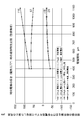
- 6 is a graph comparing the linear characteristics depending on the presence / absence of a guard / shield for the electrodes and the diameter of the opposing electrodes when there is an inclination between the electrodes. 6 is a graph comparing the linear characteristics depending on the presence / absence of a guard / shield for the electrodes and the diameter of the opposing electrodes when there is an inclination between the electrodes. It is the graph which showed the value of the residual for each strain gauge when there is inclination between electrodes. It is a schematic diagram of the electric force line in the capacitance type strain gauge as a prior art.
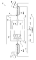
- FIG. 1 is an overall configuration diagram of a strain measurement system 1 according to the first embodiment.
- the strain measuring system 1 includes a capacitance type strain gauge 10 and a measuring device 20.
- the capacitance type strain gauge 10 has a conductive guard that faces each other and surrounds the electrodes 11A and 11B having the same size on the facing surfaces and the electrodes 11A and 11B with the facing surfaces open. 12A and shield 12B, cable 30A which connects electrode 11A and measuring device 20, and cable 30B which connects electrode 11B and measuring device 20 are provided.
- An insulator 13A is provided between the electrode 11A and the guard 12A, and an insulator 13B is provided between the electrode 11B and the shield 12B.
- the insulators 13A and 13B are preferably in the air (air atmosphere).
- the electrodes 11A and 11B are arranged such that their respective facing surfaces are orthogonal to the strain measurement direction, and the areas of the facing surfaces where the electrodes 11A and 11B face each other are the same.
- the linear characteristic is approximated to the linear characteristic of the parallel plate electrode model at infinity, by minimizing the edge effect of the electrode, as described in Examples described later.
- this accuracy is improved in obtaining the characteristic curve during instrument calibration.
- the electrodes 11A and 11B can be realized by using, for example, electrodes of platinum or platinum alloy that are less affected by high temperature corrosion.
- the conductive guard 12A surrounds the electrode 11A in a state where the surface of the electrode 11A facing the electrode 11B is open.
- the conductive shield 12B surrounds the electrode 11B in a state where the surface of the electrode 11B facing the electrode 11A is open.
- the guard 12A is connected to the neutral point of the measuring device 20 to maintain the zero potential, while the shield 12B is electrically insulated from the guard 12A and both electrodes 11A and 11B, It is floating.
- the material of the guard 12A and the shield 12B is preferably a high temperature resistant material such as Inconel, which is a conductor such as a metal having a thermal expansion coefficient equivalent to that of the electrode material and which is less affected by high temperature corrosion.
- the measuring device 20 is an LCR meter equipped with an automatic balancing bridge circuit, and measures the capacitance between the electrodes 11A and 11B.
- the LCR meter adjusts the neutral point to the zero potential of the measuring circuit by an AC self-balancing bridge circuit.
- the cable 30 includes a cable 30A connecting the electrode 11A and the measuring device 20 and a cable 30B connecting the electrode 11B and the measuring device 20.
- the cable 30A is a heat-resistant biaxial sheath cable such as an MI cable, and includes a core wire 31A, an inner jacket 32A that surrounds the core wire 31A and has electrical continuity, and an outer jacket 33A that surrounds the inner jacket 32A and has electrical continuity.
- a heat resistant insulator (not shown) between the inner cover 32A and the outer cover 33A is provided.
- the cable 30B is also a high temperature resistant biaxial sheath cable such as an MI cable, and has a core wire 31B, an inner jacket 32B that surrounds the core wire 31B and has continuity, and an outer jacket that surrounds the inner jacket 32B and has continuity.
- 33B and a heat-resistant insulator (not shown) between the inner cover 32B and the outer cover 33B.
- the core wire 31A of the cable 30A connects the electrode 11A to the high-side current terminal (Hc) and the high-side voltage terminal (Hp) of the measuring device 20.
- the core wire 31B of the cable 30B connects the electrode 11B to the low-side current terminal (Lc) and the low-side voltage terminal (Lp) of the measuring device 20.
- the end portion of the inner sheath 32A of the cable 30A on the guard 12A side and the end portion of the inner sheath 32B of the cable 30B on the shield 12B side are connected by a conductor wire 35.
- the entire inner jacket 32A of the cable 30A is covered with the outer jacket 33A that is electrically insulated from the electrodes 11A and 11B and is grounded, and the entire inner jacket 32B of the cable 30B covers the electrodes 11A and the electrodes. 11B is covered with a jacket 33B that is electrically insulated and grounded.
- a conductor 36 connects the end of the inner cover 32A of the cable 30A opposite to the guard 12A and the end of the inner cover 32B of the cable 30B opposite to the shield 12B.
- the conducting wire 36 further connects these both ends to the neutral point of the measuring device 20. As described above, the neutral point of the measuring device 20, the inner cover 32A of the cable 30A, and the inner cover 32B of the cable 30B are connected, and thus the measurement value by the measuring device 20 is stabilized.
- the inner coat 32A of the cable 30A and the guard 12A are connected by a conductor 37.
- the shield 12B is not connected to the inner jacket 32B of the cable 30B, and the shield 12B floats. Further, the jacket 33A of the cable 30A and the jacket 33B of the cable 30B are grounded. Therefore, in the conversion formula of the electrode interval using the basic formula of capacitance, the linearity is improved and the amount of noise mixed in the measurement result is reduced.
- the conductive guard 12A surrounds the electrode 11A in a state where the surface of the electrode 11A facing the electrode 11B is open.
- the conductive shield 12B surrounds the electrode 11B in a state where the surface of the electrode 11B facing the electrode 11A is open.
- the plurality of electrodes 11A and 11B facing each other and the plurality of electrodes 11A and 11B are opened on the facing surface side.
- the guard 12A is connected to the neutral point of the measuring device 20 to maintain the zero potential, and the shield 12B is electrically insulated from the guard 12A and the electrodes 11A and 11B.
- the guard 12A is connected to the neutral point of the measuring device 20 and kept at zero potential.
- the shield 12B is electrically floating. Therefore, by suppressing the edge capacitances of both electrodes 11A and 11B, linearity is improved in the conversion formula of the electrode spacing using the basic formula of capacitance, and at the same time, the amount of noise mixed in the measurement result is reduced. To do. Further, when the mounting base of the electrode is slightly tilted, it is possible to obtain an accurate strain amount.
- the inner jacket 32A of the cable 30A is connected to the guard 12A surrounding the electrode 11A, and is connected to the inner jacket 32B of the cable 30B connected to the electrode 11B.
- the whole is covered with an outer jacket 33A that is electrically insulated from the electrodes 11A and 11B and is grounded, and the entire inner jacket 32B of the cable 30B is electrically insulated from the electrodes 11A and 11B. It is covered with an outer cover 33B that is grounded together with it.
- the inner sheath of the biaxial sheath cable that connects to the first electrode of the plurality of electrodes connects to the guard that surrounds the first electrode and connects to the second electrode of the plurality of electrodes.
- the entire inner sheath of the biaxial sheath cable is covered with an outer sheath that is electrically insulated from the electrode and is grounded, and the stray capacitance between the inner sheath and the outer sheath of the biaxial sheath cable is stabilized to measure. Value stabilizes. In particular, even under a high temperature environment, the fluctuation of the floating capacitance of the sheath is suppressed, so that an accurate strain amount can be obtained.
- the electrodes 11A and 11B have the same size. This improves the linear characteristics, among other things by minimizing the edge effects of the electrodes.
- FIG. 2 is an overall configuration diagram of the strain measurement system 1A according to the present embodiment.
- the strain measuring system 1A differs from the strain measuring system 1 in that the electrodes 11A and 11B have different sizes. More specifically, the radius of the electrode 11A is smaller than the radius of the electrode 11B.
- the guard 12A surrounding the electrode 11A and the shield 12B surrounding the electrode 11B the size of the facing surfaces facing each other is larger in the guard 12A than in the shield 12B.
- the central axis of the electrode 11A and the central axis of the electrode 11B deviate from each other because the sizes of the facing surfaces of the electrode 11A and the electrode 11B are different from each other.
- the strain measurement system 1A according to the second embodiment is inferior in linear characteristics at normal times as compared with the strain measurement system 1 according to the first embodiment, as described in Examples below, When there is a misalignment of the axis between them, a remarkable effect is exhibited in terms of linear characteristics.
- the sizes of the plurality of electrodes are different from each other, the guard surrounds the small diameter electrode, and the shield surrounds the large diameter electrode.
- the influence of the displacement of the axial center of the electrode or the vibration is suppressed, and the tolerance for the step on the mounting surface of the capacitance type strain gauge is increased.
- Numerical analysis was performed by electric field simulation to find out how the linear characteristics change depending on whether or not a plurality of electrodes have the same diameter and whether or not the electrodes are surrounded by a guard or a shield.
- the simulation was based on a finite element analysis using a three-dimensional model with a standard mesh size of 3 mm and an air mesh size of 0.1 mm, and an electric field analysis was performed.
- Femtet registered trademark
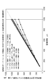
- FIG. 4 is a graph comparing the linear characteristics depending on the presence / absence of a guard / shield for the electrodes and the diameters of the opposing electrodes in a normal state, that is, when there is no deviation between the core wires of the two electrodes and the two electrodes are parallel to each other. is there.
- the horizontal axis is the electrode spacing when the electrode spacing of the electrode surfaces facing each other in parallel is widened stepwise in the vertical direction
- the vertical axis is the capacitance analysis value of the electric field analysis model, the capacitance of the parallel plate electrodes. It is the electrode spacing as a converted value obtained by regression using the conversion formula (the above formula (1)).
- the difference between the value on the vertical axis and the value on the horizontal axis is smaller in the strain gauge in which the electrode is surrounded by the guard or shield than in the strain gauge in which the electrode does not surround the guard. Further, the strain gauge in which the guard surrounds the High electrode and the shield surrounds the Low electrode is better than the strain gauge in which the guard surrounds both the High electrode and the Low electrode, or the strain gauge in which the guard surrounds only the High electrode, The difference between the value on the vertical axis and the value on the horizontal axis is small.
- FIG. 5 is a graph in which the horizontal axis is the same as that of FIG. 4, but the vertical axis is the above difference, that is, the residual difference obtained by subtracting the value of the horizontal axis from the value of the vertical axis in FIG.
- the absolute value of the residual is the smallest in the strain gauge in which the High electrode is surrounded by the guard, the Low electrode is surrounded by the shield, and the two electrodes have the same diameter.
- the High electrode is surrounded by the guard
- the Low electrode is surrounded by the shield
- the absolute value of the residual error in the strain gauge in which the sizes of the two electrodes are different is the second smallest.
- the absolute values of residuals in other strain gauges are much larger than the absolute values of residuals in these strain gauges.
- FIG. 6 is a graph showing the residual value for each strain gauge when the values on the horizontal axis in FIG. 5 are 500 ⁇ m and 1,000 ⁇ m.
- the absolute value of the residual is the smallest in the strain gauge in which the High electrode is surrounded by the guard, the Low electrode is surrounded by the shield, and the two electrodes have the same diameter. Is surrounded by a guard, the Low electrode is surrounded by a shield, and the strain gauge in which the two electrodes have different sizes is the second smallest.
- the strain gauge in which the guard surrounds the High electrode and the shield surrounds the Low electrode is better than other strain gauges.
- the two strain gauges with the same diameter are better than the strain gauges with two different diameters. High linear characteristics.
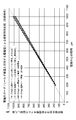
- FIG. 7A shows that when the distance between the center lines of two 15 ⁇ electrodes is 0.2 mm, the center of the electrode is maintained while maintaining a tilted state (declination: 0.77 °) where the proximity distance of the electrode ends is 0.1 mm.
- the distance between the lines is the electrode distance when stepwise widening to 1 mm in the vertical direction, and the vertical axis represents the capacitance analysis value of the electric field analysis model using the capacitance conversion formula of the parallel plate electrodes (the above formula). It is an electrode interval as a converted value obtained by regression in (1)).
- FIG. 7A shows that when the distance between the center lines of two 15 ⁇ electrodes is 0.2 mm, the center of the electrode is maintained while maintaining a tilted state (declination: 0.77 °) where the proximity distance of the electrode ends is 0.1 mm.
- the distance between the lines is the electrode distance when stepwise widening to 1 mm in the vertical direction, and the vertical axis represents the capacitance analysis value of the electric field analysis model
- the strain gauge in which both the High electrode and the Low electrode are surrounded by the guard and the strain gauge in which only the High electrode is surrounded by the guard has a smaller difference between the value on the vertical axis and the value on the horizontal axis.
- the horizontal axis is the same as that of FIGS. 7A and 7B, while the vertical axis is the above difference, that is, the value of the horizontal axis is changed from the value of the vertical axis in each of FIGS. 7A and 7B. It is the graph which made the residual deducted.
- the absolute value of the residual is the highest in the strain gauge in which the High electrode is surrounded by the guard, the Low electrode is surrounded by the shield, and the two electrodes have the same diameter. small.
- the High electrode is surrounded by the guard, the Low electrode is surrounded by the shield, and the absolute value of the residual error in the strain gauge in which the sizes of the two electrodes are different is the second smallest.
- the absolute values of residuals in other strain gauges are much larger than the absolute values of residuals in these strain gauges.
- the variation of the absolute value of the residual when the deviation angle increases from 0.77 ° to 1.52 ° shows that the electrodes have different diameters.
- the strain gauge in which the High electrode is surrounded by the guard and the Low electrode is surrounded by the shield is smaller than the other strain gauges.
- FIG. 9 is a bar graph showing, for each strain gauge, the residual value when the value on the horizontal axis is 1,000 ⁇ m in FIGS. 8A and 8B.
- the absolute value of the residual is such that the High electrode is surrounded by the guard, the Low electrode is surrounded by the shield, and the two electrodes have the same diameter.
- the strain gauge is the smallest, the High electrode is surrounded by the guard, the Low electrode is surrounded by the shield, and the strain gauge in which the two electrodes have different sizes is the second smallest.
- the strain gauge in which the guard surrounds the High electrode and the shield surrounds the Low electrode has higher linear characteristics than the other electrodes, and the inclination or inclination between the electrodes is high.
- the influence on the linear characteristic due to the fluctuation of is small.
- the two strain gauges having the same diameter have higher linear characteristics than the strain gauges having the two electrodes having different diameters. ..
- the difference in the residual between when the declination is 0.77 ° and when the declination is 1.53 ° is the same when the two electrodes have the same diameter and the two electrodes have different diameters.
- the value ( ⁇ 10) is shown. That is, the change in the residual due to the change in the declination does not change between a strain gauge with two electrodes having the same diameter and a strain gauge with two electrodes having different diameters.
Landscapes
- Physics & Mathematics (AREA)
- General Physics & Mathematics (AREA)
- Measurement Of Length, Angles, Or The Like Using Electric Or Magnetic Means (AREA)
Abstract
ひずみ量の測定において、誤差の発生を極力防止することにより、基本式からのずれ量を低減し、より正確なひずみ量を得ることが可能な、静電容量式ひずみ計を提供する。 互いに対向する複数の電極11と、前記複数の電極の各々を前記対向面側が開放された状態で包囲し、導電性を有するガード12A及びシールド12Bと、複数の電極11の各々と計測装置20とを接続する、複数の2軸シースケーブル30とを備える。
Description
本発明は、静電容量式ひずみ計及びひずみ計測システムに関する。
従来、配管溶接部のひずみ測定において溶接部を跨ぐ配管表面にひずみ計を取り付けて、溶接部のひずみを計測する方法が知られている。とりわけ、高温環境下で発生するひずみを計測する方法として、特許文献1は、電極面を高温環境下においても変化しない空気を媒体として近接させることで、この電極間の静電容量からひずみ量を算定する計測方法を開示している。
測定対象物の2点間のひずみ量(離隔)を対象物の表面に取り付け測定するため、この2箇所に離隔方向と垂直に平行平板電極を対向するよう取り付け、この電極間の静電容量値の変動量から、電極間隔の変位量を換算し、取得する計測においては、以下の式(1)に示す無限遠の平行平板電極の静電容量の基本式を基準として、換算することができる。

しかし、電極面積が有限の場合、図10に示すような電極外周部の縁端容量により、静電容量の測定値は、向かい合った電極面積と電極間隔とから基本式を用いた換算により得られる静電容量値より大きくなる。すなわち、測定される静電容量値と向かい合った電極面積とから、基本式により得られる電極間隔は、実際の電極間隔よりみかけ上小さくなる。これにより、正確なひずみ量を得ることができない。
電極外周部の縁端容量による基本式からのずれは、計器のサイズ、構造、電気特性の点で、当該計器固有の特性に依存する。そこで、この特性を計測し、基本式からの補正を行う方法があるが、この方法では、計器特性の計測、及び補正における誤差が加味されることとなる。
また、対向する電極を測定表面に取り付ける際、各電極の中心軸がずれた場合も、同様に基本式からのずれが生じ、誤差が発生する原因となる。
また、配管の周溶接部のクリープひずみを測定するために、この溶接部を跨ぎ配管表面に対向して取り付ける電極間隔の測定において、溶接部の均一な伸びに加え曲げ変形が生じる場合があることから電極面の角度ズレや角度の変動により、あらかじめ設定した特性曲線からのズレが生じることになる。
高温環境下において静電容量を測定する各電極に接続する信号ケーブルは、被覆の腐食や近接する部材等、外界との浮遊容量の変動により、測定回路全体のコンダクタンスの変動により、測定値が安定しない。
本発明は、ひずみ量の測定において、誤差の発生を極力防止することにより、静電容量の基本式からのずれ量を低減し、より正確なひずみ量を得ることが可能な、静電容量式ひずみ計を提供することを目的とする。
前記目的を達成するため、本発明は、次に記載する構成を備えている。
(1) 互いに対向する複数の電極と、前記複数の電極の各々を前記対向面側が開放された状態で包囲し、導電性を有するガード及びシールドと、前記複数の電極の各々と、前記電極間の静電容量を計測する計測装置とを接続する、複数の2軸シースケーブルとを備える、静電容量式ひずみ計。
(2) (1)に記載の静電容量式ひずみ計において、前記ガード及びシールドのうち、前記ガードは、前記計測装置の中性点に接続されてゼロ電位が保たれ、前記シールドは前記ガード及び前記電極とは電気的に絶縁されている。
(3) (1)又は(2)に記載の静電容量式ひずみ計において、前記複数の電極のうち第1の電極に接続する前記2軸シースケーブルの内被が、前記第1の電極を包囲する前記ガード、及び前記複数の電極のうち第2の電極に接続する前記2軸シースケーブルの内被と接続し、前記第1の電極に接続する前記2軸シースケーブルと前記第2の電極に接続する前記2軸シースケーブルの内被全体が、前記電極とは電気的に絶縁されると共に接地される外被で覆われる。
(4) (1)~(3)のいずれかに記載の静電容量ひずみ計であって、前記複数の電極の大きさが同一である。
(5) (1)~(3)のいずれかに記載の静電容量ひずみ計であって、前記複数の電極の大きさが互いに異なり、前記ガードは小径電極を包囲し、前記シールドは大径電極を包囲する。
(6) (1)~(5)のいずれかに記載の静電容量式ひずみ計と、前記計測装置とを備える、ひずみ計測システム。
本発明によれば、静電容量式ひずみ計を用いたひずみ量の測定において、誤差の発生を極力防止することにより、静電容量の基本式からのずれ量を低減し、より正確なひずみ量を得ることが可能となる。
〔1 第1実施形態〕
以下、本発明の第1実施形態について各図面を参照しながら詳述する。
〔1.1 発明の構成〕
図1は、第1実施形態に係るひずみ計測システム1の全体構成図である。ひずみ計測システム1は、静電容量式ひずみ計10と、計測装置20とを備える。
以下、本発明の第1実施形態について各図面を参照しながら詳述する。
〔1.1 発明の構成〕
図1は、第1実施形態に係るひずみ計測システム1の全体構成図である。ひずみ計測システム1は、静電容量式ひずみ計10と、計測装置20とを備える。
静電容量式ひずみ計10は、互いに対向し、対向面の大きさが同一の電極11A及び11Bと、電極11A及び11Bの各々を対向面側が開放された状態で包囲する、導電性を有するガード12A及びシールド12Bと、電極11Aと計測装置20とを接続するケーブル30Aと、電極11Bと計測装置20とを接続するケーブル30Bとを備える。また、電極11Aとガード12Aとの間には、絶縁体13Aが備わり、電極11Bとシールド12Bとの間には、絶縁体13Bが備わる。なお、絶縁体13A及び絶縁体13Bは、気中(空気雰囲気)であるとよい。
より具体的には、電極11A及び11Bは、各々の対向面が、ひずみの計測方向に直交するように配置され、電極11Aと電極11Bとが向かい合う対向面の面積は同一である。これにより、後述の実施例に記載するように、大きさに限りのある電極でも、電極の縁端効果の最小化によって、線形特性が、無限遠の並行平板電極のモデルの線形特性に近似するよう向上し、計器校正時の特性曲線の取得においてこの精度が向上する。なお、電極11A及び電極11Bは、例えば、高温腐食の影響が少ないプラチナ又はプラチナ合金の電極を用いて実現することが可能である。
また、導電性を有するガード12Aは、電極11Aの電極11Bに対する対向面が開放された状態で、電極11Aを包囲する。同様に、導電性を有するシールド12Bは、電極11Bの電極11Aに対する対向面が開放された状態で、電極11Bを包囲する。更に、後述のように、ガード12Aは計測装置20の中性点に接続され、ゼロ電位が保たれる一方で、シールド12Bはガード12A及び双方の電極11A及び11Bとは電気的に絶縁され、浮遊している。なお、ガード12A及びシールド12Bの材質は、熱膨張率が電極材と同等の金属等の導電体で、かつ高温腐食の影響が少ないインコネル等の耐高温材料が適する。
計測装置20は、自動平衡ブリッジ回路を備えたLCRメータであり、電極11A及び電極11B間の静電容量を測定する。LCRメータは、交流の自動平衡ブリッジ回路により、中性点を計測回路のゼロ電位に調整する。
ケーブル30は、電極11Aと計測装置20とを接続するケーブル30Aと、電極11Bと計測装置20とを接続するケーブル30Bとを備える。
ケーブル30Aは、MIケーブル等の耐熱性の2軸シースケーブルであって、芯線31Aと、芯線31Aを包囲し導通のある内被32Aと、内被32Aを包囲し導通のある外被33Aと、内被32Aと外被33Aとの間の耐熱性の絶縁体(不図示)とを備える。同様に、ケーブル30Bも、MIケーブル等の耐高温の2軸シースケーブルであって、芯線31Bと、芯線31Bを包囲し導通のある内被32Bと、内被32Bを包囲し導通のある外被33Bと、内被32Bと外被33Bとの間の、耐熱性の絶縁体(不図示)とを備える。
ケーブル30Aの芯線31Aは、電極11Aと、計測装置20のHigh側の電流端子(Hc)及びHigh側の電圧端子(Hp)とを接続する。ケーブル30Bの芯線31Bは、電極11Bと、計測装置20のLow側の電流端子(Lc)及びLow側の電圧端子(Lp)とを接続する。
更に、ケーブル30Aの内被32Aのガード12A側端部と、ケーブル30Bの内被32Bのシールド12B側端部とは、導線35によって接続される。また、ケーブル30Aの内被32Aの全体が、電極11A及び電極11Bとは電気的に絶縁されると共に接地される外被33Aで覆われ、ケーブル30Bの内被32Bの全体が、電極11A及び電極11Bとは電気的に絶縁されると共に接地される外被33Bで覆われる。電極11A及び電極11B間の静電容量を計測する際、ガード12Aと13Aに芯線(導体)31Aと芯線(導体)31Bとは逆向きの電流が流れることになり、ケーブル30A及びケーブル30Bのインダクタンスによる影響を抑えることで、計測装置20による測定値は安定する。
ケーブル30Aの内被32Aの、ガード12Aと反対側の端部と、ケーブル30Bの内被32Bの、シールド12Bと反対側の端部とは、導線36によって接続される。導線36は、更にこれら両端部と、計測装置20の中性点とを接続する。このように、計測装置20の中性点と、ケーブル30Aの内被32A、及びケーブル30Bの内被32Bとが接続されることにより、計測装置20による測定値は安定する。
ケーブル30Aの内被32Aとガード12Aとは、導線37によって接続される。一方、シールド12Bは、ケーブル30Bの内被32Bとは互いに接続されず、シールド12Bは浮遊する。更に、ケーブル30Aの外被33Aとケーブル30Bの外被33Bとは、接地される。このため、静電容量の基本式を用いた電極間隔の換算式において、線形性が向上し、測定結果に混入するノイズの量が減少する。
上記のように、ひずみ計測システム1の静電容量式ひずみ計10においては導電性を有するガード12Aは、電極11Aの電極11Bに対する対向面が開放された状態で、電極11Aを包囲する。同様に、導電性を有するシールド12Bは、電極11Bの電極11Aに対する対向面が開放された状態で、電極11Bを包囲する。これにより、電極11Aと電極11Bの外周部の縁端容量を抑えることにより、静電容量の測定値と、基本式を用いた換算により得られる静電容量値とのずれが減少し、より正確なひずみ量を得ることが可能となる。
〔1.2 第1実施が奏する効果〕
以上、説明したように構成された本実施形態によれば、静電容量ひずみ計1は、互いに対向する複数の電極11A及び11Bと、複数の電極11A及び11Bの各々を対向面側が開放された状態で包囲し、導電性を有するガード12A及びシールド12Bと、複数の電極11A及び11Bの各々と、電極間の静電容量を計測する計測装置20とを接続する、複数の2軸シースケーブル30A及び30Bとを備える。
電極外周部の縁端容量を抑えるガード及びシールドを備えることにより、静電容量の基本式からのずれ量を低減し、より正確なひずみ量を得ることが可能となる。
以上、説明したように構成された本実施形態によれば、静電容量ひずみ計1は、互いに対向する複数の電極11A及び11Bと、複数の電極11A及び11Bの各々を対向面側が開放された状態で包囲し、導電性を有するガード12A及びシールド12Bと、複数の電極11A及び11Bの各々と、電極間の静電容量を計測する計測装置20とを接続する、複数の2軸シースケーブル30A及び30Bとを備える。
電極外周部の縁端容量を抑えるガード及びシールドを備えることにより、静電容量の基本式からのずれ量を低減し、より正確なひずみ量を得ることが可能となる。
また、本実施形態によれば、ガード12Aは、計測装置20の中性点に接続されてゼロ電位が保たれ、シールド12Bはガード12Aおよび電極11A及び11Bとは電気的に絶縁されている。
これにより、ガード12Aは、計測装置20の中性点に接続されゼロ電位に保たれる。また、シールド12Bは、電気的に浮遊している。このため、両電極11A及び11Bの縁端容量を抑えることにより、静電容量の基本式を用いた電極間隔の換算式において、線形性が向上すると同時に、測定結果に混入するノイズの量が減少する。更に、電極の取付台座に若干の傾きが生じた場合に、正確なひずみ量を得ることが可能となる。
これにより、ガード12Aは、計測装置20の中性点に接続されゼロ電位に保たれる。また、シールド12Bは、電気的に浮遊している。このため、両電極11A及び11Bの縁端容量を抑えることにより、静電容量の基本式を用いた電極間隔の換算式において、線形性が向上すると同時に、測定結果に混入するノイズの量が減少する。更に、電極の取付台座に若干の傾きが生じた場合に、正確なひずみ量を得ることが可能となる。
また、本実施形態によれば、ケーブル30Aの内被32Aが、電極11Aを包囲するガード12Aに接続し、電極11Bに接続するケーブル30Bの内被32Bと接続し、ケーブル30Aの内被32Aの全体が、電極11A及び電極11Bとは電気的に絶縁されると共に接地される外被33Aで覆われ、ケーブル30Bの内被32Bの全体が、電極11A及び電極11Bとは電気的に絶縁されると共に接地される外被33Bで覆われる。
これにより、静電容量の基本式を用いた電極間隔の換算式において、線形性が向上すると同時に、測定結果に混入するノイズの量が減少する。より詳細には、複数の電極のうち第1の電極に接続する2軸シースケーブルの内被が、第1の電極を包囲するガードに接続し、複数の電極のうち第2の電極に接続する2軸シースケーブルの内被と接続することで、各電極に接続するシースケーブルの内被間の電位差を打ち消すと共に、LCRメータの中性点電位に安定させ、2軸シースケーブルの芯線とシース間の浮遊容量が低減されることで、測定する電極間の静電容量以外の静電容量を低減すると同時に、測定値が安定する。
更に、2軸シースケーブルの内被全体が、電極とは電気的に絶縁されると共に接地された外被で覆われ、2軸シースケーブル内被と外側との浮遊容量を安定させることで、測定値が安定する。とりわけ、高温環境下においても、シースの浮遊容量の変動が抑制されることで、正確なひずみ量を得ることが可能となる。
これにより、静電容量の基本式を用いた電極間隔の換算式において、線形性が向上すると同時に、測定結果に混入するノイズの量が減少する。より詳細には、複数の電極のうち第1の電極に接続する2軸シースケーブルの内被が、第1の電極を包囲するガードに接続し、複数の電極のうち第2の電極に接続する2軸シースケーブルの内被と接続することで、各電極に接続するシースケーブルの内被間の電位差を打ち消すと共に、LCRメータの中性点電位に安定させ、2軸シースケーブルの芯線とシース間の浮遊容量が低減されることで、測定する電極間の静電容量以外の静電容量を低減すると同時に、測定値が安定する。
更に、2軸シースケーブルの内被全体が、電極とは電気的に絶縁されると共に接地された外被で覆われ、2軸シースケーブル内被と外側との浮遊容量を安定させることで、測定値が安定する。とりわけ、高温環境下においても、シースの浮遊容量の変動が抑制されることで、正確なひずみ量を得ることが可能となる。
また、本実施形態によれば、電極11Aと電極11Bの大きさは同一である。これにより、とりわけ電極の縁端効果の最小化により線形特性が向上する。
〔2 第2実施形態〕
以下、本発明の第2実施形態について各図面を参照しながら詳述する。なお、以下では説明の簡略化のため、主として第2実施形態に係るひずみ計測システム1Aが、第1実施形態に係るひずみ計測システム1と異なる点について説明する。
以下、本発明の第2実施形態について各図面を参照しながら詳述する。なお、以下では説明の簡略化のため、主として第2実施形態に係るひずみ計測システム1Aが、第1実施形態に係るひずみ計測システム1と異なる点について説明する。
〔2.1 発明の構成〕
図2は、本実施形態に係るひずみ計測システム1Aの全体構成図である。ひずみ計測システム1Aは、ひずみ計測システム1と異なり、電極11Aと電極11Bの大きさが異なる。より詳細には、電極11Aの半径は、電極11Bの半径よりも小さい。これに伴い、電極11Aを包囲するガード12Aと、電極11Bを包囲するシールド12Bとを比較すると、互いに対向する対向面の大きさは、ガード12Aの方がシールド12Bよりも大きい。
図2は、本実施形態に係るひずみ計測システム1Aの全体構成図である。ひずみ計測システム1Aは、ひずみ計測システム1と異なり、電極11Aと電極11Bの大きさが異なる。より詳細には、電極11Aの半径は、電極11Bの半径よりも小さい。これに伴い、電極11Aを包囲するガード12Aと、電極11Bを包囲するシールド12Bとを比較すると、互いに対向する対向面の大きさは、ガード12Aの方がシールド12Bよりも大きい。
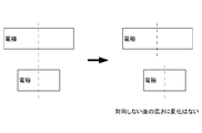
仮に電極11Aと電極11Bの大きさが同一であれば、双方の中心軸がずれた場合、図3Aに示すように、双方の電極が対向しない面が新たに発生する。これにより、静電容量の測定値と、基本式を用いた換算により得られる静電容量値との間にずれが発生する。
しかし、図3Bに示すように、第2実施形態においては、電極11Aと電極11Bの対向面の大きさが互いに異なることにより、電極11Aの中心軸と、電極11Bの中心軸とが互いにずれたとしても、双方の電極が対向しない面の広さに変化はなく、静電容量の測定値と、基本式を用いた換算により得られる静電容量値とのずれが、より小さな値に留まるため、より正確なひずみ量を得ることが可能となる。
しかし、図3Bに示すように、第2実施形態においては、電極11Aと電極11Bの対向面の大きさが互いに異なることにより、電極11Aの中心軸と、電極11Bの中心軸とが互いにずれたとしても、双方の電極が対向しない面の広さに変化はなく、静電容量の測定値と、基本式を用いた換算により得られる静電容量値とのずれが、より小さな値に留まるため、より正確なひずみ量を得ることが可能となる。
すなわち、第2実施形態に係るひずみ計測システム1Aは、第1実施形態に係るひずみ計測システム1に比較して、後述の実施例に記載のように、通常時には線形特性の点で劣るものの、電極間で軸芯のズレが生じた場合には線形特性の点で顕著な効果を発揮する。
〔2.2 第2実施形態が奏する効果〕
以上、説明したように構成された本実施形態によれば、複数の電極の大きさが互いに異なり、前記ガードは小径電極を包囲し、前記シールドは大径電極を包囲する。
これにより、とりわけ電極の軸芯のズレや振動の影響が抑制され、静電容量式ひずみ計の取り付け面の段差に対する許容度が上昇する。
以上、説明したように構成された本実施形態によれば、複数の電極の大きさが互いに異なり、前記ガードは小径電極を包囲し、前記シールドは大径電極を包囲する。
これにより、とりわけ電極の軸芯のズレや振動の影響が抑制され、静電容量式ひずみ計の取り付け面の段差に対する許容度が上昇する。
〔3 実施例〕
複数の電極が同径か否か、及び、電極をガードやシールドが包囲するか否かに応じて、線形特性がどのように変化するかを、電界シミュレーションにより数値解析した。なお、シミュレーションは、標準メッシュサイズ3mm、空気メッシュサイズ0.1mmの3次元モデルを用いた有限要素解析によるものであり、電場解析を実行した。シミュレーションソフトとしては、ムラタソフトウェア製のFemtet(登録商標)ver.2017.1.2を用いた。
複数の電極が同径か否か、及び、電極をガードやシールドが包囲するか否かに応じて、線形特性がどのように変化するかを、電界シミュレーションにより数値解析した。なお、シミュレーションは、標準メッシュサイズ3mm、空気メッシュサイズ0.1mmの3次元モデルを用いた有限要素解析によるものであり、電場解析を実行した。シミュレーションソフトとしては、ムラタソフトウェア製のFemtet(登録商標)ver.2017.1.2を用いた。
〔3.1 軸芯方向の線形特性〕
図4は、通常時、すなわち2つの電極の芯線間にズレがなく、2つの電極が並行しているときの、電極に対するガード/シールドの有無及び対向する電極径による線形特性を比較するグラフである。横軸は、並行に向かい合う電極面の電極間隔を垂直方向に段階的に広げた時の電極間隔であり、縦軸は、電場解析モデルの静電容量解析値を、並行平板電極の静電容量換算式(上記の式(1))にて回帰して得られる、換算値としての電極間隔である。
図4は、通常時、すなわち2つの電極の芯線間にズレがなく、2つの電極が並行しているときの、電極に対するガード/シールドの有無及び対向する電極径による線形特性を比較するグラフである。横軸は、並行に向かい合う電極面の電極間隔を垂直方向に段階的に広げた時の電極間隔であり、縦軸は、電場解析モデルの静電容量解析値を、並行平板電極の静電容量換算式(上記の式(1))にて回帰して得られる、換算値としての電極間隔である。
図4から分かるように、電極をガードが包囲しないひずみ計より、電極をガード又はシールドが包囲するひずみ計の方が、縦軸の値と横軸の値との相違が小さい。更に、High電極をガードが、Low電極をシールドが包囲するひずみ計の方が、High電極とLow電極の双方をガードが包囲するひずみ計や、High電極のみをガードが包囲するひずみ計よりも、縦軸の値と横軸の値との相違が小さい。
図5は、横軸は図4と同一である一方で、縦軸を上記の相違、すなわち図4における縦軸の値から横軸の値を差し引いた残差としたグラフである。
図5のグラフから明らかなように、残差の絶対値は、High電極がガードによって包囲され、Low電極がシールドによって包囲されると共に、2つの電極が同径であるひずみ計が最も小さい。同様に、High電極がガードによって包囲され、Low電極がシールドによって包囲されると共に、2つの電極の大きさが異なるひずみ計での残差の絶対値が2番目に小さい。
一方、その他のひずみ計における残差の絶対値は、これらのひずみ計における残差の絶対値よりもはるかに大きい。
一方、その他のひずみ計における残差の絶対値は、これらのひずみ計における残差の絶対値よりもはるかに大きい。
図6は、図5において、横軸の値が500μmと1,000μmのときの残差の値を、各ひずみ計ごとに示したグラフである。図6からも明らかなように、残差の絶対値は、High電極がガードによって包囲され、Low電極がシールドによって包囲されると共に、2つの電極が同径であるひずみ計が最も小さく、High電極がガードによって包囲され、Low電極がシールドによって包囲されると共に、2つの電極の大きさが異なるひずみ計が、2番目に小さい。
すなわち、2つの電極間で芯線間にズレがなく、2つの電極が並行している場合には、High電極をガードが包囲し、Low電極をシールドが包囲するひずみ計が、その他のひずみ計よりも線形特性が高く、High電極をガードが包囲し、Low電極をシールドが包囲するひずみ計の中でも、2つの電極が同径のひずみ計の方が、2つの電極が異径のひずみ計よりも線形特性が高い。
〔3.2 傾き状態の線形特性〕
図7Aは、2つの15Φ電極の中心線における間隔が0.2mmのときにおいて、電極端部の近接距離が0.1mmとなる傾き状態(偏角:0.77°)を維持しながら、中心線における間隔を、垂直方向に1mmまで段階的に広げた時の電極間隔であり、縦軸は、電場解析モデルの静電容量解析値を、並行平板電極の静電容量換算式(上記の式(1))にて回帰して得られる、換算値としての電極間隔である。
また、図7Bは、2つの15Φ電極の中心線における間隔が0.2mmのときにおいて、電極端部の近接距離が0.2mmとなる傾き状態(偏角:1.52°)を維持しながら、中心線における間隔を、垂直方向に1.2mmまで段階的に広げた時の電極間隔であり、縦軸は、電場解析モデルの静電容量解析値を、並行平板電極の静電容量換算式(上記の式(1))にて回帰して得られる、換算値としての電極間隔である。
図7Aは、2つの15Φ電極の中心線における間隔が0.2mmのときにおいて、電極端部の近接距離が0.1mmとなる傾き状態(偏角:0.77°)を維持しながら、中心線における間隔を、垂直方向に1mmまで段階的に広げた時の電極間隔であり、縦軸は、電場解析モデルの静電容量解析値を、並行平板電極の静電容量換算式(上記の式(1))にて回帰して得られる、換算値としての電極間隔である。
また、図7Bは、2つの15Φ電極の中心線における間隔が0.2mmのときにおいて、電極端部の近接距離が0.2mmとなる傾き状態(偏角:1.52°)を維持しながら、中心線における間隔を、垂直方向に1.2mmまで段階的に広げた時の電極間隔であり、縦軸は、電場解析モデルの静電容量解析値を、並行平板電極の静電容量換算式(上記の式(1))にて回帰して得られる、換算値としての電極間隔である。
図7A及び図7Bから分かるように、High電極及びLow電極の双方をガードが包囲しているひずみ計や、High電極のみをガードが包囲しているひずみ計よりも、電極が同径であれ異径であれ、High電極がガードによって包囲され、Low電極がシールドによって包囲されるひずみ計の方が、縦軸の値と横軸の値との相違が小さい。
図8A及び図8Bの各々は、横軸は図7A及び図7Bと同一である一方で、縦軸を上記の相違、すなわち図7A及び図7Bの各々における縦軸の値から横軸の値を差し引いた残差としたグラフである。
図8A及び図8Bのグラフから明らかなように、残差の絶対値は、High電極がガードによって包囲され、Low電極がシールドによって包囲されると共に、2つの電極が同径であるひずみ計が最も小さい。同様に、High電極がガードによって包囲され、Low電極がシールドによって包囲されると共に、2つの電極の大きさが異なるひずみ計での残差の絶対値が2番目に小さい。
一方、その他のひずみ計における残差の絶対値は、これらのひずみ計における残差の絶対値よりもはるかに大きい。
一方、その他のひずみ計における残差の絶対値は、これらのひずみ計における残差の絶対値よりもはるかに大きい。
更に、図8Aのグラフと図8Bのグラフとを比較すると、偏角が0.77°から1.52°に増加した際の残差の絶対値の変動は、電極が同径であれ異径であれ、High電極がガードによって包囲され、Low電極がシールドによって包囲されるひずみ計の方が、その他のひずみ計よりも小さい。
図9は、図8A及び図8Bにおいて、横軸の値が1,000μmのときの残差の値を、各ひずみ計ごとに示した棒グラフである。図8A及び図8Bと同様、図9からも明らかなように、残差の絶対値は、High電極がガードによって包囲され、Low電極がシールドによって包囲されると共に、2つの電極が同径であるひずみ計が最も小さく、High電極がガードによって包囲され、Low電極がシールドによって包囲されると共に、2つの電極の大きさが異なるひずみ計が、2番目に小さい。
すなわち、2つの電極が互いに傾いている場合にも、High電極をガードが包囲し、Low電極をシールドが包囲するひずみ計が、その他の電極よりも線形特性が高いと共に、電極間の傾きや傾きの変動による線形特性への影響は小さい。
更に、High電極をガードが包囲し、Low電極をシールドが包囲するひずみ計の中でも、2つの電極が同径のひずみ計の方が、2つの電極が異径のひずみ計よりも線形特性が高い。
ただし、偏角が0.77°のときと、1.53°のときとでの残差の相違は、2つの電極が同径のひずみ計と2つの電極が異径のひずみ計とで同一の値(Δ10)を示す。すなわち偏角の変化に伴う残差の変化は、2つの電極が同径のひずみ計と2つの電極が異径のひずみ計とで変わらない。
ただし、偏角が0.77°のときと、1.53°のときとでの残差の相違は、2つの電極が同径のひずみ計と2つの電極が異径のひずみ計とで同一の値(Δ10)を示す。すなわち偏角の変化に伴う残差の変化は、2つの電極が同径のひずみ計と2つの電極が異径のひずみ計とで変わらない。
以上、本発明の実施形態について説明したが、本発明は前述した実施形態に限るものではない。また、本実施形態に記載された効果は、本発明から生じる最も好適な効果を列挙したに過ぎず、本発明による効果は、本実施形態に記載されたものに限定されるものではない。
1 1A ひずみ計測システム
10 静電容量式ひずみ計
11A 11B 電極
12A ガード
12B シールド
13A 13B 絶縁体
20 計測装置
30 30A 30B ケーブル
31A 31B 芯線
32A 32B 内被
33A 33B 外被
35 36 導線
10 静電容量式ひずみ計
11A 11B 電極
12A ガード
12B シールド
13A 13B 絶縁体
20 計測装置
30 30A 30B ケーブル
31A 31B 芯線
32A 32B 内被
33A 33B 外被
35 36 導線
Claims (6)
- 互いに対向する複数の電極と、
前記複数の電極の各々を前記対向面側が開放された状態で包囲し、導電性を有するガード及びシールドと、
前記複数の電極の各々と、前記電極間の静電容量を計測する計測装置とを接続する、複数の2軸シースケーブルとを備える、静電容量式ひずみ計。 - 前記ガード及び前記シールドのうち、前記ガードは、前記計測装置の中性点に接続されてゼロ電位が保たれ、前記シールドは前記ガード及び前記電極とは電気的に絶縁されている、請求項1に記載の静電容量式ひずみ計。
- 前記複数の電極のうち第1の電極に接続する前記2軸シースケーブルの内被が、前記第1の電極を包囲する前記ガードに接続し、前記複数の電極のうち第2の電極に接続する前記2軸シースケーブルの内被と接続し、前記第1の電極に接続する2軸シースケーブルと前記第2の電極に接続する2軸シースケーブルの内被全体が、前記電極とは電気的に絶縁されると共に接地される外被で覆われる、請求項1又は2に記載の静電容量式ひずみ計。
- 前記複数の電極の大きさが同一である、請求項1~3のいずれか1項に記載の静電容量式ひずみ計。
- 前記複数の電極の大きさが互いに異なり、前記ガードは小径電極を包囲し、前記シールドは大径電極を包囲する、請求項1~3のいずれか1項に記載の静電容量式ひずみ計。
- 請求項1~5のいずれかに記載の静電容量式ひずみ計と、
前記計測装置とを備える、ひずみ計測システム。
Priority Applications (2)
| Application Number | Priority Date | Filing Date | Title |
|---|---|---|---|
| JP2019516027A JP6573051B1 (ja) | 2018-11-01 | 2018-11-01 | 静電容量式ひずみ計及びひずみ計測システム |
| PCT/JP2018/040732 WO2020090087A1 (ja) | 2018-11-01 | 2018-11-01 | 静電容量式ひずみ計及びひずみ計測システム |
Applications Claiming Priority (1)
| Application Number | Priority Date | Filing Date | Title |
|---|---|---|---|
| PCT/JP2018/040732 WO2020090087A1 (ja) | 2018-11-01 | 2018-11-01 | 静電容量式ひずみ計及びひずみ計測システム |
Publications (1)
| Publication Number | Publication Date |
|---|---|
| WO2020090087A1 true WO2020090087A1 (ja) | 2020-05-07 |
Family
ID=67909520
Family Applications (1)
| Application Number | Title | Priority Date | Filing Date |
|---|---|---|---|
| PCT/JP2018/040732 Ceased WO2020090087A1 (ja) | 2018-11-01 | 2018-11-01 | 静電容量式ひずみ計及びひずみ計測システム |
Country Status (2)
| Country | Link |
|---|---|
| JP (1) | JP6573051B1 (ja) |
| WO (1) | WO2020090087A1 (ja) |
Citations (6)
| Publication number | Priority date | Publication date | Assignee | Title |
|---|---|---|---|---|
| JPH09280806A (ja) * | 1996-04-09 | 1997-10-31 | Nissan Motor Co Ltd | 静電容量式変位計 |
| US20050270041A1 (en) * | 2004-06-03 | 2005-12-08 | General Electric Company | Non-contact capacitive sensor and cable with dual layer active shield |
| JP2007085959A (ja) * | 2005-09-26 | 2007-04-05 | Jeol Ltd | 静電容量式変位センサー |
| JP2008191110A (ja) * | 2007-02-07 | 2008-08-21 | Denso Corp | 2電極型静電容量センサ、車両用乗員検出装置及び車両用乗員保護システム |
| JP2009257795A (ja) * | 2008-04-12 | 2009-11-05 | Kajima Corp | 鉄筋コンクリート構造物の被り厚さ管理方法 |
| JP2011128096A (ja) * | 2009-12-21 | 2011-06-30 | Wacoh Corp | 変位センサおよび力検出装置 |
-
2018
- 2018-11-01 JP JP2019516027A patent/JP6573051B1/ja active Active
- 2018-11-01 WO PCT/JP2018/040732 patent/WO2020090087A1/ja not_active Ceased
Patent Citations (6)
| Publication number | Priority date | Publication date | Assignee | Title |
|---|---|---|---|---|
| JPH09280806A (ja) * | 1996-04-09 | 1997-10-31 | Nissan Motor Co Ltd | 静電容量式変位計 |
| US20050270041A1 (en) * | 2004-06-03 | 2005-12-08 | General Electric Company | Non-contact capacitive sensor and cable with dual layer active shield |
| JP2007085959A (ja) * | 2005-09-26 | 2007-04-05 | Jeol Ltd | 静電容量式変位センサー |
| JP2008191110A (ja) * | 2007-02-07 | 2008-08-21 | Denso Corp | 2電極型静電容量センサ、車両用乗員検出装置及び車両用乗員保護システム |
| JP2009257795A (ja) * | 2008-04-12 | 2009-11-05 | Kajima Corp | 鉄筋コンクリート構造物の被り厚さ管理方法 |
| JP2011128096A (ja) * | 2009-12-21 | 2011-06-30 | Wacoh Corp | 変位センサおよび力検出装置 |
Also Published As
| Publication number | Publication date |
|---|---|
| JP6573051B1 (ja) | 2019-09-11 |
| JPWO2020090087A1 (ja) | 2021-02-15 |
Similar Documents
| Publication | Publication Date | Title |
|---|---|---|
| CA2853602C (en) | Electrostatic capacitance fluid level sensor | |
| JP6459188B2 (ja) | 非接触電圧計測装置 | |
| CN105829899A (zh) | 电压传感器 | |
| CN111602039B (zh) | 用于监测连接到气体绝缘开关设备的电缆的电缆接头的温度的装置和方法 | |
| CN105829898A (zh) | 电压感测装置 | |
| JP2008298761A (ja) | 電流センサ | |
| US10359330B2 (en) | Pressure sensor | |
| CN1319180A (zh) | 机电转换器 | |
| WO2016189864A1 (ja) | プローブ及びそれを用いた電圧測定装置 | |
| JP6573051B1 (ja) | 静電容量式ひずみ計及びひずみ計測システム | |
| KR102692157B1 (ko) | 격막 진공계 | |
| JP6841116B2 (ja) | ひずみ計測システム | |
| US4939930A (en) | Electric capacitance strain gauge | |
| JP6143926B1 (ja) | 圧力センサ | |
| JPH0226723B2 (ja) | ||
| JP4873348B2 (ja) | 電流センサおよび電流検出装置 | |
| EP0067675B1 (en) | Position measurement | |
| JP4662307B2 (ja) | ポリイミドをコーティングしたシース熱電対 | |
| JP2005127784A (ja) | 非接触電圧測定装置 | |
| CN103348425A (zh) | 仪表用变压器 | |
| KR20020022620A (ko) | 벤딩 및 횡단력에 민감하지 않는 기계적/전기적 변환기 | |
| KR20020022621A (ko) | 벤딩 모멘트 센서 | |
| JP6776552B2 (ja) | 歪計性能判定装置、歪計性能判定方法 | |
| JPH02126103A (ja) | 容量型ひずみゲージ | |
| GB2275533A (en) | System for structural monitoring |
Legal Events
| Date | Code | Title | Description |
|---|---|---|---|
| ENP | Entry into the national phase |
Ref document number: 2019516027 Country of ref document: JP Kind code of ref document: A |
|
| 121 | Ep: the epo has been informed by wipo that ep was designated in this application |
Ref document number: 18938695 Country of ref document: EP Kind code of ref document: A1 |
|
| NENP | Non-entry into the national phase |
Ref country code: DE |
|
| 122 | Ep: pct application non-entry in european phase |
Ref document number: 18938695 Country of ref document: EP Kind code of ref document: A1 |