WO2020085311A1 - Optical distance measurement device and optical distance measurement method - Google Patents
Optical distance measurement device and optical distance measurement method Download PDFInfo
- Publication number
- WO2020085311A1 WO2020085311A1 PCT/JP2019/041332 JP2019041332W WO2020085311A1 WO 2020085311 A1 WO2020085311 A1 WO 2020085311A1 JP 2019041332 W JP2019041332 W JP 2019041332W WO 2020085311 A1 WO2020085311 A1 WO 2020085311A1
- Authority
- WO
- WIPO (PCT)
- Prior art keywords
- light
- unit
- distance measuring
- light receiving
- range
- Prior art date
Links
Images


Classifications
-
- G—PHYSICS
- G02—OPTICS
- G02B—OPTICAL ELEMENTS, SYSTEMS OR APPARATUS
- G02B26/00—Optical devices or arrangements for the control of light using movable or deformable optical elements
- G02B26/08—Optical devices or arrangements for the control of light using movable or deformable optical elements for controlling the direction of light
- G02B26/10—Scanning systems
- G02B26/101—Scanning systems with both horizontal and vertical deflecting means, e.g. raster or XY scanners
-
- G—PHYSICS
- G01—MEASURING; TESTING
- G01C—MEASURING DISTANCES, LEVELS OR BEARINGS; SURVEYING; NAVIGATION; GYROSCOPIC INSTRUMENTS; PHOTOGRAMMETRY OR VIDEOGRAMMETRY
- G01C3/00—Measuring distances in line of sight; Optical rangefinders
- G01C3/02—Details
- G01C3/06—Use of electric means to obtain final indication
-
- G—PHYSICS
- G01—MEASURING; TESTING
- G01S—RADIO DIRECTION-FINDING; RADIO NAVIGATION; DETERMINING DISTANCE OR VELOCITY BY USE OF RADIO WAVES; LOCATING OR PRESENCE-DETECTING BY USE OF THE REFLECTION OR RERADIATION OF RADIO WAVES; ANALOGOUS ARRANGEMENTS USING OTHER WAVES
- G01S17/00—Systems using the reflection or reradiation of electromagnetic waves other than radio waves, e.g. lidar systems
- G01S17/02—Systems using the reflection of electromagnetic waves other than radio waves
- G01S17/06—Systems determining position data of a target
- G01S17/08—Systems determining position data of a target for measuring distance only
- G01S17/10—Systems determining position data of a target for measuring distance only using transmission of interrupted, pulse-modulated waves
-
- G—PHYSICS
- G01—MEASURING; TESTING
- G01S—RADIO DIRECTION-FINDING; RADIO NAVIGATION; DETERMINING DISTANCE OR VELOCITY BY USE OF RADIO WAVES; LOCATING OR PRESENCE-DETECTING BY USE OF THE REFLECTION OR RERADIATION OF RADIO WAVES; ANALOGOUS ARRANGEMENTS USING OTHER WAVES
- G01S17/00—Systems using the reflection or reradiation of electromagnetic waves other than radio waves, e.g. lidar systems
- G01S17/02—Systems using the reflection of electromagnetic waves other than radio waves
- G01S17/06—Systems determining position data of a target
- G01S17/42—Simultaneous measurement of distance and other co-ordinates
-
- G—PHYSICS
- G01—MEASURING; TESTING
- G01S—RADIO DIRECTION-FINDING; RADIO NAVIGATION; DETERMINING DISTANCE OR VELOCITY BY USE OF RADIO WAVES; LOCATING OR PRESENCE-DETECTING BY USE OF THE REFLECTION OR RERADIATION OF RADIO WAVES; ANALOGOUS ARRANGEMENTS USING OTHER WAVES
- G01S7/00—Details of systems according to groups G01S13/00, G01S15/00, G01S17/00
- G01S7/48—Details of systems according to groups G01S13/00, G01S15/00, G01S17/00 of systems according to group G01S17/00
- G01S7/481—Constructional features, e.g. arrangements of optical elements
- G01S7/4814—Constructional features, e.g. arrangements of optical elements of transmitters alone
-
- G—PHYSICS
- G01—MEASURING; TESTING
- G01S—RADIO DIRECTION-FINDING; RADIO NAVIGATION; DETERMINING DISTANCE OR VELOCITY BY USE OF RADIO WAVES; LOCATING OR PRESENCE-DETECTING BY USE OF THE REFLECTION OR RERADIATION OF RADIO WAVES; ANALOGOUS ARRANGEMENTS USING OTHER WAVES
- G01S7/00—Details of systems according to groups G01S13/00, G01S15/00, G01S17/00
- G01S7/48—Details of systems according to groups G01S13/00, G01S15/00, G01S17/00 of systems according to group G01S17/00
- G01S7/481—Constructional features, e.g. arrangements of optical elements
- G01S7/4816—Constructional features, e.g. arrangements of optical elements of receivers alone
-
- G—PHYSICS
- G01—MEASURING; TESTING
- G01S—RADIO DIRECTION-FINDING; RADIO NAVIGATION; DETERMINING DISTANCE OR VELOCITY BY USE OF RADIO WAVES; LOCATING OR PRESENCE-DETECTING BY USE OF THE REFLECTION OR RERADIATION OF RADIO WAVES; ANALOGOUS ARRANGEMENTS USING OTHER WAVES
- G01S7/00—Details of systems according to groups G01S13/00, G01S15/00, G01S17/00
- G01S7/48—Details of systems according to groups G01S13/00, G01S15/00, G01S17/00 of systems according to group G01S17/00
- G01S7/481—Constructional features, e.g. arrangements of optical elements
- G01S7/4817—Constructional features, e.g. arrangements of optical elements relating to scanning
-
- G—PHYSICS
- G01—MEASURING; TESTING
- G01S—RADIO DIRECTION-FINDING; RADIO NAVIGATION; DETERMINING DISTANCE OR VELOCITY BY USE OF RADIO WAVES; LOCATING OR PRESENCE-DETECTING BY USE OF THE REFLECTION OR RERADIATION OF RADIO WAVES; ANALOGOUS ARRANGEMENTS USING OTHER WAVES
- G01S7/00—Details of systems according to groups G01S13/00, G01S15/00, G01S17/00
- G01S7/48—Details of systems according to groups G01S13/00, G01S15/00, G01S17/00 of systems according to group G01S17/00
- G01S7/483—Details of pulse systems
- G01S7/486—Receivers
- G01S7/4861—Circuits for detection, sampling, integration or read-out
-
- G—PHYSICS
- G01—MEASURING; TESTING
- G01S—RADIO DIRECTION-FINDING; RADIO NAVIGATION; DETERMINING DISTANCE OR VELOCITY BY USE OF RADIO WAVES; LOCATING OR PRESENCE-DETECTING BY USE OF THE REFLECTION OR RERADIATION OF RADIO WAVES; ANALOGOUS ARRANGEMENTS USING OTHER WAVES
- G01S7/00—Details of systems according to groups G01S13/00, G01S15/00, G01S17/00
- G01S7/48—Details of systems according to groups G01S13/00, G01S15/00, G01S17/00 of systems according to group G01S17/00
- G01S7/483—Details of pulse systems
- G01S7/486—Receivers
- G01S7/487—Extracting wanted echo signals, e.g. pulse detection
-
- G—PHYSICS
- G02—OPTICS
- G02B—OPTICAL ELEMENTS, SYSTEMS OR APPARATUS
- G02B27/00—Optical systems or apparatus not provided for by any of the groups G02B1/00 - G02B26/00, G02B30/00
- G02B27/10—Beam splitting or combining systems
- G02B27/14—Beam splitting or combining systems operating by reflection only
Definitions
- the present disclosure relates to a technique of optically measuring a distance to an object using a laser beam.
- the above disclosure is excellent because it can measure the distance to an object in a wide area, but it has been desired to be further downsized because it is incorporated into various moving bodies such as vehicles and equipment. In order to meet such a demand for downsizing, it has been particularly required to downsize the optical system. When an area is scanned two-dimensionally, the optical system becomes complicated, the size of a scanning mirror or prism tends to increase, and the load of signal processing for measuring the distance also increases.
- the aspect of the present disclosure is an optical distance measuring device using a laser beam.
- This optical distance measuring device emits a laser beam for detecting at least two pixels in a predetermined direction and a laser beam from the light emitting unit in a first direction corresponding to the predetermined direction.
- a first scanning unit that scans over at least a predetermined angle of view, and a reflector that reflects the laser light scanned by the first scanning unit, and the laser light is defined as the first direction.
- a second scanning unit that scans in a second direction intersecting and over a predetermined range outside, and receives reflected light from an object existing in the predetermined range; and the reflector of the second scanning unit.
- the path changing unit for returning the reflected light from the object to the light receiving lens side, and the reflected light from the object condensed by the light receiving lens.
- Receive at least 2 pixels for detection A light receiving unit including an element, a light emitting unit, a distance measuring unit that detects a distance to the target object according to a time until the light receiving unit receives the reflected light from the target object, Equipped with.
- the first scanning unit is provided between the light emitting unit and the route changing unit, and the first scanning unit, the route changing unit, and the second scanning unit are different from the first scanning unit.
- the laser light may pass through the path changing unit and reach the second scanning unit.
- the irradiation range of the laser light can be changed in the first direction and the second direction to perform distance measurement, and the angle of view of the light scanning in both directions can be expanded.
- the laser light emitted at one time is for at least two pixels, and the light receiving unit for receiving this can also receive light for at least two pixels at a time, so that distance measurement at a plurality of locations can be performed at one time. As a result, it is possible to measure a wide range in a short time.
- FIG. 1 is a schematic configuration diagram of the optical distance measuring device of the first embodiment
- FIG. 2 is an explanatory diagram showing the configuration of the light receiving element
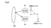
- FIG. 3 is an explanatory diagram showing the principle of optical distance measurement
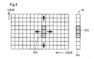
- FIG. 4 is an explanatory diagram showing the relationship between the scanning range and the light receiving element
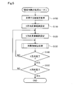
- FIG. 5 is a flowchart showing an in-region detection processing routine
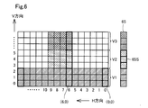
- FIG. 6 is an explanatory diagram showing an example of detection in a region
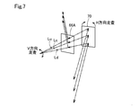
- FIG. 7 is an explanatory diagram showing a main part of another embodiment
- FIG. 8 is explanatory drawing which shows the principal part of other embodiment.
- the optical distance measuring device 10 includes an optical system 30 that irradiates a laser beam toward a target and receives the reflected light, and a SPAD calculation unit 100 that measures the distance.
- the optical system 30 includes a light emitting unit 40, a V direction scanning unit 50 corresponding to the first scanning unit, a light receiving unit 60, and an H direction scanning unit 70 corresponding to the second scanning unit.
- the light emitting unit 40 includes a laser element 41 that emits laser light for distance measurement, a circuit board 43 that incorporates a drive circuit for the laser element 41, and a collimator lens 45 that makes the laser light emitted from the laser element 41 parallel light.
- the laser element 41 is a laser diode capable of oscillating a so-called short pulse laser, and the pulse width of the laser light is about 5 nsec. By using a short pulse of 5 nsec, it is possible to improve the resolution of distance measurement.
- the laser element 41 includes a total of three light emitting elements arranged in one direction. Therefore, the laser light emitted for distance measurement also has a shape elongated in one direction. As will be described later, the longitudinal direction of the laser light is the vertical direction (also referred to as the V direction) when the laser light is emitted for distance measurement.
- the V-direction scanning unit 50 includes a surface reflecting mirror 51 that reflects the laser light that is collimated by the collimator lens 45, a rotating shaft 54 that rotatably supports the surface reflecting mirror 51, and a rotary that rotates the rotating shaft 54.
- a solenoid 55 is provided.
- the rotary solenoid 55 receives a control signal Sm1 from the outside and repeats normal rotation and reverse rotation within a predetermined angle range (hereinafter referred to as a field angle range).
- a field angle range a predetermined angle range
- the rotary shaft 54, and thus the surface reflecting mirror 51 also rotates within this range.
- the laser light incident from the laser element 41 via the collimator lens 45 is scanned in the vertical direction (V direction) within a predetermined angle of view range.
- a combiner 66 corresponding to a route changing unit is provided in this scanning range.
- the combiner 66 is a reflecting mirror having an opening 68 at the center.
- the laser beam scanned in the vertical direction by the surface reflecting mirror 51 passes through the opening 68 and enters the surface reflecting mirror 71 of the H-direction scanning unit 70.
- the combiner 66 is a fixed reflecting mirror, and the reflecting surface is the back side in FIG.
- the laser light that has passed through the opening 68 of the combiner 66 is reflected by the surface reflecting mirror 71 of the H-direction scanning unit 70 and output to the outside.
- the H-direction scanning unit 70 includes a surface reflecting mirror 71, a rotary shaft 74 that rotatably supports the surface reflecting mirror 71, and a rotary solenoid 75 that rotationally drives the rotary shaft 74.
- the rotary solenoid 75 receives a control signal Sm2 from the outside and repeats normal rotation and reverse rotation within a predetermined angle range. As a result, the rotating shaft 74, and thus the surface reflecting mirror 71, also rotates within this range. As a result, the laser light incident through the opening 68 is scanned in the horizontal direction (H direction) within a predetermined angle range.
- the laser light emitted from the light emitting unit 40 is scanned in the vertical direction (V direction) and the horizontal direction (H direction). Therefore, the laser light output from the optical distance measuring device 10 scans within the scanning range 80 schematically shown in FIG. 1 in the V direction and the H direction.
- the laser light is diffusely reflected on the surface, and a part of the laser light returns to the H-direction scanning unit 70.
- the reflected light is reflected by the surface reflecting mirror 71, returns toward the combiner 66, is reflected by the surface of the combiner 66, and goes to the light receiving unit 60.
- the reflected light reflected by the mirror surface of the combiner 66 enters the light receiving lens 61 of the light receiving unit 60, is condensed by the light receiving lens 61, and enters the light receiving array 65 in which the light receiving elements 65a shown in FIG. 2 are arranged.
- the laser element 41 is a laser element having a vertically long emission angle.
- the emission angle of the laser element 41 corresponds to the angle of view of three pixels as the light receiving element 65a of the light receiving section 60.
- the vertical direction in this case means the V direction in the scanning range 80.
- the vertical direction of the drawing corresponds to the vertical direction of the emission angle of the laser element 41.
- the vertically long laser beam is scanned in the up-down direction (V direction) on the surface reflecting mirror 71 by the normal rotation and reverse rotation of the surface reflecting mirror 51, and the laser beam reflected by the surface reflecting mirror 71 is in the scanning range.
- scanning is performed in the V direction.
- the surface reflection mirror 71 of the H-direction scanning unit 70 rotates forward and backward in a predetermined angle range, so that the laser light long in the V direction is scanned in the H direction in the scanning range 80. .
- the vertically long laser light can be scanned within the scanning range 80 by the V direction scanning unit 50 and the H direction scanning unit 70.
- the scanned laser light is reflected by the object OBJ, follows the above-described path, and is incident on the light receiving element 65a of the light receiving unit 60.
- the light receiving array 65 has a plurality of light receiving elements 65a arranged in the vertical direction.
- the arrangement of the light receiving elements 65a has a size corresponding to the maximum range (V direction angle of view) scanned by the V direction scanning unit 50 in the V direction.
- an avalanche photodiode APD is used in order to realize high response and excellent detection ability.
- the operation modes of the APD include a linear mode in which the reverse bias voltage is lower than the breakdown voltage and a Geiger mode in which the reverse bias voltage is higher than the breakdown voltage.
- the output current from the APD is almost proportional to the amount of incident light.
- the avalanche phenomenon can occur even when a single photon is incident, so the detection sensitivity can be further increased.
- Such an APD operated in the Gaiga mode may be referred to as a single photon avalanche diode (SPAD: Single Photon Avalanche Diode).
- each light receiving element 65a has a quench resistor Rq and an avalanche diode Da connected in series between a power supply Vcc and a ground line, and the voltage at the connection point is calculated as a logical operation element. It is input to the inverting element INV, which is one of the two, and is converted into a digital signal whose voltage level is inverted. Since the output of the inverting element INV is connected to one input of the AND circuit SW, if the other input is at the high level H, it is directly output to the outside. The other input state of the AND circuit SW can be switched by the selection signal SC.
- the selection signal SC is used to specify from which light-receiving element 65a of the light-receiving array 65 the signal is to be read out, and therefore may be referred to as an address signal.
- an analog switch may be used instead of the AND circuit SW.
- a PIN photodiode may be used instead of the avalanche diode Da.
- the avalanche diode Da If no light is incident on the light receiving element 65a, the avalanche diode Da is kept in a non-conducting state. Therefore, the input side of the inverting element INV is held in the pulled-up state, that is, the high level H, through the quench resistor Rq. Therefore, the output of the inverting element INV is kept at the low level L.
- the avalanche diode Da is turned on by the incident light (photons). As a result, a large current flows through the quench resistor Rq, the input side of the inverting element INV once becomes low level L, and the output of the inverting element INV is inverted to high level H.
- the inverting element INV outputs a pulse signal that becomes high level for a very short time when light (photons) enters each light receiving element 65a.
- the output signal of the AND circuit SW that is, the output signal Sout from each light receiving element 65a, is output from the avalanche diode Da. It will reflect the state.
- each light receiving element 65a The output Sout of each light receiving element 65a is generated when the laser element 41 emits light and the light is reflected back to the object OBJ existing in the scanning range 80. Therefore, as shown in FIG. 3, after the light emitting unit 40 is driven and the laser light (hereinafter referred to as irradiation light pulse) is output, the reflected light pulse reflected by the object OBJ is each light receiving element of the light receiving unit 60.
- the distance to the target can be detected by measuring the time Tf until the detection by 65a.
- the object OBJ can be present in various positions from near to far from the optical distance measuring device 10. Therefore, the scanning range 80 in FIG. 1 does not show that the distance of the optical range finder 10 is uniform, but schematically shows the scanning range by the laser light.
- the light receiving element 65a outputs a pulse signal when receiving the reflected light.
- the pulse signal output from the light receiving element 65a is input to the SPAD operation unit 100 corresponding to the distance measuring unit.
- the SPAD operation unit 100 causes the laser element 41 to emit light to scan an external space, and from the time from the time when the laser element 41 outputs the irradiation light pulse to the time when the light receiving array 65 of the light receiving unit 60 receives the reflected light pulse. , Calculates the distance to the object OBJ.
- the SPAD calculation unit 100 includes a well-known CPU and memory, and executes a program prepared in advance to perform processing required for distance measurement.
- the SPAD calculation unit 100 includes an addition unit 120, a histogram generation unit 135, a peak detection unit 140, a distance calculation unit 150, and the like, in addition to the control unit 110 that performs overall control.
- the adder 120 is a circuit that adds the outputs of a larger number of light receiving elements included in one light receiving element 65a.
- one light receiving element 65a is depicted as having one output Sout, but in reality, one light receiving element 65a has N ⁇ N (N is an integer of 2 or more) inside. Is provided, and when the reflected light enters the light receiving element 65a, N ⁇ N elements are operated.
- 7 ⁇ 7 SPADs are provided in one light receiving element 65a.
- the number and arrangement of SPADs can be variously configured, such as 5 ⁇ 9, for example, other than 7 ⁇ 7.
- the reason why the light receiving element 65a is composed of a plurality of SPADs is due to the characteristics of the SPADs.
- the SPAD can detect only one photon, but the detection of the SPAD by the limited light from the object OBJ must be probabilistic.
- the addition unit 120 of the SPAD calculation unit 100 adds the output signal Sout from the SPAD that can detect the reflected light only stochastically and reliably detects the reflected light.
- the reflected light pulse (FIG. 3) thus obtained is received by the histogram generation unit 135.
- the histogram generation unit 135 adds the addition results of the addition unit 120 a plurality of times to generate a histogram.
- the signal detected by the light receiving element 65a includes noise, but when the signals from the respective light receiving elements 65a for a plurality of irradiation light pulses are added together, the signals corresponding to the reflected light pulses are accumulated and correspond to noise. Since the signals are not cumulative, the signal corresponding to the reflected light pulse becomes clear. Therefore, the peak detection unit 140 detects the peak of the signal by analyzing the histogram from the histogram generation unit 135. The peak of the signal is nothing but the reflected light pulse in FIG.
- the distance calculation unit 150 can detect the distance D to the object by detecting the time Tf from the irradiation light pulse to the peak of the reflected light pulse.
- the detected distance D is output to the outside, for example, if the optical distance measuring device 10 is mounted in an automatic driving vehicle, the automatic driving device or the like. Of course, it can be used as a fixed distance measuring device as well as a moving body such as a drone, an automobile, or a ship.
- the control unit 110 instructs the circuit board 43 of the light emitting unit 40 to generate a histogram, in addition to the command signal SL that determines the light emission timing of the laser element 41, the address signal Sout that determines which light receiving element 65a to activate. It outputs a signal St for instructing the generation timing of the histogram for the unit 135 and drive signals Sm1, Sm2 for the rotary solenoids 55, 75 of the V direction scanning unit 50 and the H direction scanning unit 70. The control unit 110 outputs these signals at a predetermined timing, so that the SPAD operation unit 100 detects the object OBJ that may exist in the scanning range 80 together with the distance D to the OBJ.
- FIG. 4 is an explanatory diagram showing the relationship between the scanning range 80 and the light receiving unit 60.
- a plurality of light receiving elements 65a (nine in FIG. 4) are arranged in the light receiving array 65 in the vertical direction (V direction), and one of the light receiving elements 65a receives three light receiving elements.
- the alignment of the optical system 30 is adjusted so that the reflected light is incident on the element 65a.
- a group of three light receiving elements 65a on which the reflected light is incident is called a light receiving area 65S.
- the V direction scanning unit 50 when the V direction scanning unit 50 is driven to change the angle of view of the surface reflecting mirror 51, the incident position of the reflected light on the light receiving array 65 moves in the V direction.
- the light receiving unit 60 including the combiner 66 is provided between the V direction scanning unit 50 and the H direction scanning unit 70. Therefore, in the light receiving array 65, a plurality of light receiving elements 65a are prepared in the V direction.
- a plurality of pixels in the H direction may be prepared, combined with pixels in the V direction prepared for a plurality of pixels, and these may be scanned as one block.
- the light receiving pixels other than the light receiving area 65S may be turned off, or an operation for measuring ambient light may be performed.
- the SPAD operation unit 100 executes the in-region detection processing routine shown in FIG.
- the SPAD calculation unit 100 first acquires the area to be scanned (step S100).
- the area to be scanned is a range in which the optical system 30 is driven and the irradiation light pulse is output.
- the scanning range 80 shown in FIG. 1 shows an example in which the scanning region is a substantially rectangular range. In the present embodiment, this scanning area is not limited to a substantially rectangular shape and can be set in advance.
- the SPAD calculation unit 100 may define the scanning area by itself, or may be provided from the outside, for example, from an automatic driving device.
- the scanning range 80 is divided into three in the V direction, and the region corresponding to the lowermost stage V1 is scanned over the entire range in the H direction, and is divided into a region corresponding to V2 in the middle stage and V3 in the uppermost stage. In the corresponding area, only a predetermined central area is scanned.
- the scanning of the scanning range 80 is first performed in the V direction and then in the H direction. Therefore, when the area to be scanned is acquired, the scanning range in the H direction is set next (step S110).
- the H-direction scanning range is from one end to the other end of the scanning range 80.
- the SPAD calculation unit 100 controls the V-direction scanning unit 50 and the H-direction scanning unit 70 so that the illumination position of the laser light is the origin, here, the scanning range 80 on the right side in the figure. Set to the lower position (0,0).
- the scanning range in the V direction is set (step S120).
- the scanning range in the V direction at the origin position is the range V1. Therefore, the object detection process is then performed (step S130). That is, the laser light is driven at this position to output the irradiation light pulse, the reflected light from the object OBJ is detected, and the presence of the object OBJ is detected together with the distance D from the time Tf.
- step S140 it is determined whether the detection processing for the V direction is completed. If the detection in the detection range set in the V direction (here, the range V1) has not been completed, the drive signal Sm1 is output to the V direction scanning unit 50, the surface reflecting mirror 51 is slightly rotated, and the region V1 is detected. Is scanned in the V direction to continue detection of the object OBJ. When the scanning and detection in the V direction at one position in the H direction are completed (step S140: “YES”), it is determined whether scanning in the H direction is completed (step S150).
- step S150 If the scanning in the H direction is not completed (step S150: “NO”), the drive signal Sm2 is output to the H direction scanning unit 70, the surface reflecting mirror 71 is slightly rotated, and the illumination position of the laser light is changed to H. Move in the direction. Then, the scanning range in the V direction is set again (step S120).
- the area V1 is scanned in the V direction while changing the illumination position in the H direction, and detection of the object OBJ (acquisition of the distance D) is continued.
- the V direction scanning range is set to the regions V1, V2, and V3 here (step S120). Therefore, the detection processing of the object OBJ (step S130) and the scanning of the illumination position in the V direction using the V direction scanning unit 50 are determined until the detection processing of the V direction is completed (step S140: “YES”). "),repeat.
- the areas V1, V2 and V3 shown in FIG. 6 are sequentially scanned. The reflected light from these areas is detected by the corresponding light receiving element 65a of the light receiving array 65.
- the incident position of the reflected light on the light receiving array 65 also changes in the V direction.
- the scanning range in the V direction is set to the regions V1 to V3 at the positions (6, 0) to (9, 0) in the H direction.
- the scanning range in the V direction is limited to the area V1 again.
- the determination in step S150 in FIG. 5 becomes “YES”, and “END To end the processing.
- the combiner 66 is arranged between the V-direction scanning unit 50 and the H-direction scanning unit 70, and is located closer to the laser element 41 than the combiner 66 is.
- the V-direction scanning unit 50 changes the direction of the laser light in the V direction
- the H-direction scanning unit 70 changes the direction of the laser light in the H direction. Therefore, in the scanning range 80, the irradiation range of the laser light can be changed in the V direction and the H direction. Therefore, the angle of view of the light scanning in both directions can be expanded.
- the light receiving unit 60 which receives the laser light can also perform distance measurement for three pixels at a time, and perform distance measurement in a wide range in a short time. You can
- the vertically long laser beam is used from the beginning, it is not necessary to upsize the surface reflecting mirror 71 for scanning in the H direction even if the angle of view in the V direction is widened.
- the short pulse laser having a narrow emission pulse width is used as the laser element 41 and the SPAD is used as the light receiving element 65a, the detection accuracy can be improved.
- the light emission time of the irradiation light pulse can be shortened, it is possible to suppress the influence of extra light entering the light receiving unit 60 and causing disturbance during distance measurement.
- the combiner 66 having the opening 68 is used to separate the irradiation light and the reflected light, it is possible to prevent the irradiation light from being reflected by the combiner 66 and entering the light receiving section 60. The influence of disturbance can be suppressed.
- the range in which the irradiation light pulse can be irradiated can be freely set in the H direction and the V direction, so that the scanning range 80 can be limited to a part. Therefore, there is no need to wastefully measure a range that does not require distance measurement. For example, it is not necessary to measure the distance for a part that can be determined to hit the sky as seen from the vehicle.
- the time required to scan a portion that does not need to be distance-measured can be used for repeating distance-measurement in a distance-measurement area. If the number of times of distance measurement is repeated is increased, the accuracy of measurement can be increased accordingly. For example, in the example shown in FIG.
- the distance measuring range in the V direction in the central portion is widened, but the time when the scanning of the left and right V2 and V3 portions which are not distance measuring is omitted can be used for the distance measuring in the central portion. it can.
- traveling at high speed there are cases where it is desired to improve the accuracy of distance measurement in the central portion of the scanning range 80, and such a request can be met.
- the distance measurement in the turning direction is performed over a wide range, and the distance measurement is performed wider and more accurately than in other directions.
- the combiner 66 has a planar shape in the first embodiment, it may have a concave mirror shape. If this concave mirror is used as a part of an optical system that forms an image of reflected light on the light receiving array 65 of the light receiving unit 60, the optical system of the light receiving unit 60 can be downsized. For example, when the optical system of the light receiving unit 60 has a four-lens configuration, the outermost convex lens can be replaced with a concave mirror formed by the combiner 66, so that the lens configuration of the light receiving unit 60 itself is miniaturized. be able to.
- the combiner 66 in the above-described embodiment uses the opening 68 to pass the irradiation light pulse, even if the combiner 66 is a concave mirror, it does not affect the laser light on the irradiation side, which is preferable. .
- the combiner 66 having the opening 68 is used.
- the configuration for passing the laser light on the irradiation side need not be limited to the opening, and as illustrated in FIG. It is possible to employ an optical component having a function of transmitting the light of (1) and reflecting the light from the opposite side.
- a half mirror is used as the combiner 66A. As shown in FIG. 7, when the irradiation-side laser light is vertically scanned from the center Lc in the V direction, the laser light passes through the range from the uppermost line Lu to the lowermost line Ld.
- the angle from Ld to Lu is the view angle in the V direction, and in the first embodiment, the opening 68 has a length corresponding to this view angle range.
- the combiner 66A since the combiner 66A employs a half mirror, it is not necessary to provide an opening.
- the laser light passes through the combiner 66A, is reflected by the surface reflection mirror 71, is irradiated onto the scanning range 80, and is reflected back to the object.
- the returned reflected light is reflected by the surface reflecting mirror 71, is then reflected by the surface of the combiner 66A, and enters the light receiving unit 60.
- a wide angle of view can be realized with a small configuration, and distance measurement can be performed in a wide scanning range.
- a half size combiner 66B may be used as illustrated in FIG.
- the laser light passes through the range from the uppermost line Lu to the lowermost line Ld.
- the angle of view in the V direction is from Ld to Lu. Light in these ranges passes right beside the position where the combiner 66B is present, is reflected by the surface reflecting mirror 71, is irradiated onto the scanning range 80, and is reflected back to the object.
- the reflected light is reflected by the surface reflecting mirror 71, then enters the position where the combiner 66B exists, is reflected by the surface of the combiner 66B, and enters the light receiving unit 60. Also in this case, as in the first embodiment, a wide angle of view can be realized with a small configuration, and distance measurement can be performed in a wide scanning range.
- the V-direction scanning unit 50 and the H-direction scanning unit 70 are arranged with the combiner 66 sandwiched between them, but the arrangement of both may be reversed. Further, the arrangement of each unit shown in FIG. 1 may be rotated 90 degrees as it is, and the V direction and the H direction may be switched. It is sufficient that the direction scanning unit 50 and the direction scanning unit 70 can be independently scanned, and the shape of the scanning range 80 is not particularly limited to a particular shape. Further, if the light emitting portion of the laser light can scan the laser light of at least two pixels in two directions and the light receiving portion can detect at least two pixels, the combiner 66 or the half mirror may not be provided.
- the laser light from the laser element 41 has a wide angle of view in the V direction by using three light emitting elements.
- a single laser element 41 has a light emitting surface long in one direction.
- the angle of view may be widened by using a laser element having The angle of view of the laser element 41 is not limited to three pixels, but may be two pixels or more of the light receiving element 65a.
- each unit that processes the signal from each light receiving unit that is, the addition unit 120, the histogram generation unit 135, the peak detection unit 140, the distance measurement calculation unit 150, and the like are provided.
- the same number of light receiving elements 65a that simultaneously receive reflected light may be prepared, and distance measurement processing may be performed in parallel for at least each light receiving element 65a.
- the laser light of the laser element 41 has a wide angle of view, and the reflected light from the object returns to the light receiving unit 60 at the same time, so that parallel processing is possible. If the parallel processing is performed, the processing for the same scanning range 80 can be completed in a shorter time than in the case where the parallel processing is not performed.
- part of the configuration realized by hardware may be replaced with software.
- At least a part of the configuration realized by software can also be realized by a discrete circuit configuration.
- the software (computer program) can be provided in a form stored in a computer-readable recording medium.
- the "computer-readable recording medium” is not limited to a portable recording medium such as a flexible disk or a CD-ROM, but is fixed to an internal storage device in the computer such as various RAMs and ROMs, or a computer such as a hard disk. It also includes an external storage device. That is, the "computer-readable recording medium” has a broad meaning including any recording medium on which data packets can be fixed not temporarily.
- the present disclosure is not limited to the above-described embodiments, and can be realized with various configurations without departing from the spirit of the present disclosure.
- the technical features in the embodiments corresponding to the technical features in each mode described in the section of the summary of the invention are provided in order to solve some or all of the above-mentioned problems, or one of the effects described above. It is possible to appropriately replace or combine in order to achieve a part or all. If the technical features are not described as essential in this specification, they can be deleted as appropriate. For example, the following modes can be adopted.
- One aspect of the present disclosure is an optical distance measuring device using laser light.
- This optical distance measuring device emits a laser beam for detecting at least two pixels in a predetermined direction and a laser beam from the light emitting unit in a first direction corresponding to the predetermined direction.
- a first scanning unit that scans over at least a predetermined angle of view, and a reflector that reflects the laser light scanned by the first scanning unit, and the laser light is defined as the first direction.
- a second scanning unit that scans in a second direction intersecting and over a predetermined range outside, and receives reflected light from an object existing in the predetermined range; and the reflector of the second scanning unit.
- the path changing unit returning the reflected light from the object to the light receiving lens side, and detecting the reflected light from the object condensed by the light receiving lens.
- Receiving light for at least 2 pixels A light receiving unit including a child, a distance measuring unit that detects a distance to the target object according to a time from the light emission by the light emitting unit until the light receiving unit receives the reflected light from the target object, Equipped with.
- the first scanning unit is provided between the light emitting unit and the route changing unit, and the first scanning unit, the route changing unit, and the second scanning unit are the lasers from the first scanning unit.
- Light may be arranged at a position where the light passes through the path changing unit and reaches the second scanning unit.
- the path changing unit is a combiner including an opening or a slit through which the laser light passes, and the opening or the slit is the combiner for the laser light from the first scanning unit. It may have a length corresponding to the angle of view range.
- the path changing unit is a half mirror that allows the laser beam from the first scanning unit to pass therethrough and reflects the reflected light from the second scanning unit to the light receiving lens side. Good.
- the route changing unit can be easily configured.
- a short pulse laser may be used as the light emitting element of the light emitting unit. By doing so, the resolution of distance measurement can be improved.
- the path changing unit may be a concave mirror, and may serve as a part of the light receiving lens that collects the reflected light from the object toward the light receiving unit. Good. By doing so, it is possible to downsize the optical system of the light receiving unit, for example, the lens structure of the light receiving unit can be configured with one fewer lens.
- the first scanning unit and the second scanning unit may be independently drivable.
- the range for distance measurement can be set independently for the first direction and the second direction.
- the predetermined range that is the object of distance measurement may be a shape in which the first direction and the second direction are obtained by a predetermined combination. By doing so, it is possible to efficiently perform distance measurement in a range suitable for the purpose.
- the signals from the light receiving elements for at least two pixels may be processed in parallel.
- distance measurement for at least two pixels can be performed, so that the distance measurement processing can be speeded up.
- a second aspect of the present disclosure is an optical distance measuring method that optically measures a distance.
- laser light for detecting at least two pixels is emitted in a predetermined direction, and the emitted laser light is emitted in a first direction corresponding to the predetermined direction and at least in a predetermined angle of view range.
- driving a reflector that reflects the scanned laser light and scans the laser light in a second direction intersecting the first direction and in a predetermined external range.
- the path changing unit provided in the middle of the path from the reflector to the upstream side of the reflected light from the object, from the object
- the reflected light is returned to the light receiving lens side
- the reflected light from the object condensed by the light receiving lens is detected by a light receiving unit including a light receiving element for at least two pixels, and from the light emission of the laser light, Reflection from the object Depending on the time to receive said light receiving unit, to detect the distance to the object.
- the laser beam is scanned on the upstream side of the route changing unit over the first direction and the predetermined angle of view range, and the route changing unit is configured to scan the first direction and the predetermined angle of view.
- the laser beam scanned over the range may be arranged so as to pass through the path changing unit. Also by this optical distance measuring method, it is possible to measure the distance by changing the irradiation range of the laser light in the first direction and the second direction, and it is possible to widen the angle of view of the light scanning in both directions.
- the laser light emitted at one time is for at least two pixels, and the light receiving unit for receiving this can also receive light for at least two pixels at a time, so that distance measurement at a plurality of locations can be performed at one time. As a result, it is possible to measure a wide range in a short time.
- a third aspect of the present disclosure is an optical distance measuring method that optically measures a distance.
- This optical distance measuring method emits laser light for detecting at least two pixels in a predetermined direction, and emits the emitted laser light in a first direction corresponding to the predetermined direction and at least a predetermined image. Scanning over an angular range, scanning the scanned laser light in a second direction intersecting with the first direction, and over a predetermined external range, and at the same time an object in the predetermined range.
- the distance to the object is detected. Also by this optical distance measuring method, it is possible to measure the distance by changing the irradiation range of the laser light in the first direction and the second direction, and it is possible to widen the angle of view of the light scanning in both directions.
- the laser light emitted at one time is for at least two pixels, and the light receiving unit for receiving this can also receive light for at least two pixels at a time, so that distance measurement at a plurality of locations can be performed at one time. As a result, it is possible to measure a wide range in a short time.
Abstract
In the present invention, laser light for performing detection of at least two pixels in a prescribed direction is scanned in a first direction and over at least a prescribed field angle range, a reflector (71) which reflects the laser light is driven, and the laser light is scanned in a second direction intersecting the first direction over a prescribed external range. Light reflected from an object is sent back to a light-receiving lens (61) side by a path changing unit (66) provided at a point along a path from the reflector to the upstream side, and the condensed light reflected from the object is detected by a light-receiving unit (60) provided with a light-receiving element (65a) of at least two pixels so as to detect the distance to the object according to the time from light emission to light reception of the laser light. The path changing unit is disposed such that the laser light which was scanned in the first direction and over the prescribed field angle range reaches the reflector after passing through the path changing unit.
Description
本願は、2018年10月25日に日本国において出願された特許出願番号2018-200540号に基づくものであって、その優先権の利益を主張するものであり、その特許出願の全ての内容が、参照により、本願明細書に組み入れられる。
This application is based on the patent application No. 2018-200540 filed in Japan on October 25, 2018, and claims the benefit of its priority, and the entire contents of the patent application are , Incorporated herein by reference.
本開示は、レーザ光を用いて光学的に対象までの距離を測定する技術に関する。
The present disclosure relates to a technique of optically measuring a distance to an object using a laser beam.
レーザ光を所定の領域に投写し、その反射光を検出するまでに時間により、対象物までの距離を測定する測距技術が知られている。こうした測距技術では、レーザ光を2次元的に走査して、広い領域に対して、対象物までの距離を計測することが試みられている(例えば特許第4810763号公報)。
There is a known distance measurement technology that measures the distance to an object by projecting laser light on a predetermined area and detecting the reflected light. In such a distance measuring technique, it is attempted to scan a laser beam two-dimensionally and measure the distance to a target object in a wide area (for example, Japanese Patent No. 4810763).
係る開示は、広い領域において対象物までの距離を計測できる優れたものであるが、車両などの種々の移動体や設備に組み込むため、一層の小型化が望まれていた。こうした小型化の要請に応えるためには、特に光学系の小型化が求められていた。2次元的に領域を走査しようとすると、光学系が複雑化し、走査用のミラーやプリズムなどの大型化を招いてしまいがちで、かつ距離を計測する信号処理の負荷も増大する。
The above disclosure is excellent because it can measure the distance to an object in a wide area, but it has been desired to be further downsized because it is incorporated into various moving bodies such as vehicles and equipment. In order to meet such a demand for downsizing, it has been particularly required to downsize the optical system. When an area is scanned two-dimensionally, the optical system becomes complicated, the size of a scanning mirror or prism tends to increase, and the load of signal processing for measuring the distance also increases.
本開示は、以下の形態又は適用例として実現することが可能である。
The present disclosure can be realized as the following forms or application examples.
本開示の態様は、レーザ光を用いた光学的測距装置である。この光学的測距装置は、所定方向に少なくとも2画素分の検出を行なうためのレーザ光を発光する発光部と、前記発光部からの前記レーザ光を、前記所定方向に対応した第1方向に、かつ少なくとも所定の画角範囲に亘って走査する第1走査部と、前記第1走査部により走査された前記レーザ光を反射する反射体を備え、前記レーザ光を、前記第1方向とは交差する第2方向に、かつ外部の所定の範囲に亘って走査すると共に、前記所定の範囲に存在する対象物からの反射光を受ける第2走査部と、前記第2走査部の前記反射体から前記第1走査部に至る経路の途中に設けられ、前記対象物からの反射光を、受光レンズの側に折り返す経路変更部と、前記受光レンズにより集光された前記対象物から反射光を検出する少なくとも2画素分の受光素子を備えた受光部と、前記発光部による発光から、前記対象物からの反射光を前記受光部が受光するまでの時間に応じて、前記対象物までの距離を検出する測距部と、を備える。ここで、前記第1走査部は、前記発光部と前記経路変更部との間に設けられ、前記第1走査部と前記経路変更部と前記第2走査部とは、前記第1走査部からの前記レーザ光が、前記経路変更部を通り抜けて前記第2走査部に至る位置に配置されてよい。
The aspect of the present disclosure is an optical distance measuring device using a laser beam. This optical distance measuring device emits a laser beam for detecting at least two pixels in a predetermined direction and a laser beam from the light emitting unit in a first direction corresponding to the predetermined direction. And a first scanning unit that scans over at least a predetermined angle of view, and a reflector that reflects the laser light scanned by the first scanning unit, and the laser light is defined as the first direction. A second scanning unit that scans in a second direction intersecting and over a predetermined range outside, and receives reflected light from an object existing in the predetermined range; and the reflector of the second scanning unit. From the object to the first scanning unit, the path changing unit for returning the reflected light from the object to the light receiving lens side, and the reflected light from the object condensed by the light receiving lens. Receive at least 2 pixels for detection A light receiving unit including an element, a light emitting unit, a distance measuring unit that detects a distance to the target object according to a time until the light receiving unit receives the reflected light from the target object, Equipped with. Here, the first scanning unit is provided between the light emitting unit and the route changing unit, and the first scanning unit, the route changing unit, and the second scanning unit are different from the first scanning unit. The laser light may pass through the path changing unit and reach the second scanning unit.
この光学的測距装置によれば、第1方向と第2方向に、レーザ光の照射範囲を変更して測距でき、両方向に走査する光の画角を拡げることができる。しかも、一度に照射するレーザ光を少なくとも2画素分としており、これを受光する受光部も一度に少なくとも2画素分の受光ができるので、一度に複数の場所の測距を実施できる。この結果、短時間のうちに広い範囲の測距を行なうことができる。
With this optical distance measuring device, the irradiation range of the laser light can be changed in the first direction and the second direction to perform distance measurement, and the angle of view of the light scanning in both directions can be expanded. In addition, the laser light emitted at one time is for at least two pixels, and the light receiving unit for receiving this can also receive light for at least two pixels at a time, so that distance measurement at a plurality of locations can be performed at one time. As a result, it is possible to measure a wide range in a short time.
A1.第1実施形態のハードウェア構成:
図1に示すように、光学的測距装置10は、大きくは対象に向けてレーザ光を照射し反射光を受け取る光学系30と、測距を行なうSPAD演算部100とを備える。光学系30は、発光部40、第1走査部に相当するV方向走査部50、受光部60、第2走査部に相当するH方向走査部70を備える。 A1. Hardware configuration of the first embodiment:
As shown in FIG. 1, the opticaldistance measuring device 10 includes an optical system 30 that irradiates a laser beam toward a target and receives the reflected light, and a SPAD calculation unit 100 that measures the distance. The optical system 30 includes a light emitting unit 40, a V direction scanning unit 50 corresponding to the first scanning unit, a light receiving unit 60, and an H direction scanning unit 70 corresponding to the second scanning unit.
図1に示すように、光学的測距装置10は、大きくは対象に向けてレーザ光を照射し反射光を受け取る光学系30と、測距を行なうSPAD演算部100とを備える。光学系30は、発光部40、第1走査部に相当するV方向走査部50、受光部60、第2走査部に相当するH方向走査部70を備える。 A1. Hardware configuration of the first embodiment:
As shown in FIG. 1, the optical
発光部40は、測距用のレーザ光を射出するレーザ素子41、レーザ素子41の駆動回路を組み込んだ回路基板43、レーザ素子41から射出されたレーザ光を平行光にするコリメートレンズ45を備える。レーザ素子41は、いわゆる短パルスレーザを発振可能なレーザダイオードであり、レーザ光のパルス幅は、5nsec程度である。5nsecの短パルスを用いることで、測距の分解能を高めることができる。また、レーザ素子41は、全部で3つの発光素子を一方向に配列して備える。従って、測距のために照射されるレーザ光も一方向に長い形状となる。レーザ光の長手方向は、後述する様に、レーザ光が測距のための照射される場合の縦方向(V方向とも言う)とされている。
The light emitting unit 40 includes a laser element 41 that emits laser light for distance measurement, a circuit board 43 that incorporates a drive circuit for the laser element 41, and a collimator lens 45 that makes the laser light emitted from the laser element 41 parallel light. . The laser element 41 is a laser diode capable of oscillating a so-called short pulse laser, and the pulse width of the laser light is about 5 nsec. By using a short pulse of 5 nsec, it is possible to improve the resolution of distance measurement. Further, the laser element 41 includes a total of three light emitting elements arranged in one direction. Therefore, the laser light emitted for distance measurement also has a shape elongated in one direction. As will be described later, the longitudinal direction of the laser light is the vertical direction (also referred to as the V direction) when the laser light is emitted for distance measurement.
V方向走査部50は、コリメートレンズ45により平行光とされたレーザ光を反射する表面反射鏡51、この表面反射鏡51を回転可能に軸支する回転軸54、回転軸54を回転駆動するロータリソレノイド55を備える。ロータリソレノイド55は、外部からの制御信号Sm1を受けて、所定の角度範囲(以下、画角範囲という)内で正転および逆転を繰り返す。この結果、回転軸54、延いては表面反射鏡51もこの範囲で回動する。結果的にコリメートレンズ45を介してレーザ素子41から入射したレーザ光は、縦方向(V方向)に所定の画角範囲で走査される。
The V-direction scanning unit 50 includes a surface reflecting mirror 51 that reflects the laser light that is collimated by the collimator lens 45, a rotating shaft 54 that rotatably supports the surface reflecting mirror 51, and a rotary that rotates the rotating shaft 54. A solenoid 55 is provided. The rotary solenoid 55 receives a control signal Sm1 from the outside and repeats normal rotation and reverse rotation within a predetermined angle range (hereinafter referred to as a field angle range). As a result, the rotary shaft 54, and thus the surface reflecting mirror 51, also rotates within this range. As a result, the laser light incident from the laser element 41 via the collimator lens 45 is scanned in the vertical direction (V direction) within a predetermined angle of view range.
この走査範囲には、経路変更部に相当するコンバイナ66が設けられている。コンバイナ66は、中心に開口68が設けられた反射鏡である。表面反射鏡51により縦方向に走査されたレーザ光は、この開口68を通過して、H方向走査部70の表面反射鏡71に入射する。コンバイナ66は、固定の反射鏡であり、反射面は、図1における背面側である。コンバイナ66の開口68を通過したレーザ光は、H方向走査部70の表面反射鏡71に反射し、外部に出力される。H方向走査部70には、表面反射鏡71の他、表面反射鏡71を回転可能に軸支する回転軸74や、この回転軸74を回転駆動するロータリソレノイド75が備えられている。ロータリソレノイド75は、外部からの制御信号Sm2を受けて、所定の画角範囲内で正転および逆転を繰り返す。この結果、回転軸74、延いては表面反射鏡71もこの範囲で回動する。結果的に開口68を介して入射したレーザ光は、横方向(H方向)に所定の画角範囲で走査される。
A combiner 66 corresponding to a route changing unit is provided in this scanning range. The combiner 66 is a reflecting mirror having an opening 68 at the center. The laser beam scanned in the vertical direction by the surface reflecting mirror 51 passes through the opening 68 and enters the surface reflecting mirror 71 of the H-direction scanning unit 70. The combiner 66 is a fixed reflecting mirror, and the reflecting surface is the back side in FIG. The laser light that has passed through the opening 68 of the combiner 66 is reflected by the surface reflecting mirror 71 of the H-direction scanning unit 70 and output to the outside. The H-direction scanning unit 70 includes a surface reflecting mirror 71, a rotary shaft 74 that rotatably supports the surface reflecting mirror 71, and a rotary solenoid 75 that rotationally drives the rotary shaft 74. The rotary solenoid 75 receives a control signal Sm2 from the outside and repeats normal rotation and reverse rotation within a predetermined angle range. As a result, the rotating shaft 74, and thus the surface reflecting mirror 71, also rotates within this range. As a result, the laser light incident through the opening 68 is scanned in the horizontal direction (H direction) within a predetermined angle range.
2つの表面反射鏡51,71を所定範囲内で駆動することにより、発光部40が射出されたレーザ光は、縦方向(V方向)と横方向(H方向)に走査される。このため、光学的測距装置10から外部に出力されるレーザ光は、図1に模式的に示した走査範囲80内を、V方向およびH方向に走査することになる。この走査範囲80に、人や車などの対象物があると、レーザ光はその表面で乱反射し、その一部は、H方向走査部70方向に戻ってくる。この反射光は、表面反射鏡71で反射し、コンバイナ66方向に戻り、コンバイナ66の表面で反射し、受光部60に向かう。コンバイナ66の鏡面に反射した反射光は、受光部60の受光レンズ61に入射し、受光レンズ61で集光されて、図2に示した受光素子65aが配列された受光アレイ65に入射する。
By driving the two surface reflecting mirrors 51 and 71 within a predetermined range, the laser light emitted from the light emitting unit 40 is scanned in the vertical direction (V direction) and the horizontal direction (H direction). Therefore, the laser light output from the optical distance measuring device 10 scans within the scanning range 80 schematically shown in FIG. 1 in the V direction and the H direction. When an object such as a person or a car is present in the scanning range 80, the laser light is diffusely reflected on the surface, and a part of the laser light returns to the H-direction scanning unit 70. The reflected light is reflected by the surface reflecting mirror 71, returns toward the combiner 66, is reflected by the surface of the combiner 66, and goes to the light receiving unit 60. The reflected light reflected by the mirror surface of the combiner 66 enters the light receiving lens 61 of the light receiving unit 60, is condensed by the light receiving lens 61, and enters the light receiving array 65 in which the light receiving elements 65a shown in FIG. 2 are arranged.
本実施形態の光学系30では、レーザ素子41は、縦長の発光角を持ったレーザ素子である。このレーザ素子41の発光角は、受光部60の受光素子65aとして3画素分の画角に相当する。この場合の縦方向とは、走査範囲80におけるV方向という意味である。図1であれば、紙面上下方向が、レーザ素子41の発光角における縦方向に相当する。縦長のレーザ光は、表面反射鏡51の正回転・逆回転によって、表面反射鏡71上で上下方向(V方向)に走査されることになり、表面反射鏡71によって反射したレーザ光は走査範囲80において、V方向に走査されるという関係になっている。他方、H方向走査部70の表面反射鏡71が所定の画角範囲で正回転・逆回転することで、V方向に長いレーザ光は、走査範囲80において、H方向に走査されることになる。
In the optical system 30 of this embodiment, the laser element 41 is a laser element having a vertically long emission angle. The emission angle of the laser element 41 corresponds to the angle of view of three pixels as the light receiving element 65a of the light receiving section 60. The vertical direction in this case means the V direction in the scanning range 80. In FIG. 1, the vertical direction of the drawing corresponds to the vertical direction of the emission angle of the laser element 41. The vertically long laser beam is scanned in the up-down direction (V direction) on the surface reflecting mirror 71 by the normal rotation and reverse rotation of the surface reflecting mirror 51, and the laser beam reflected by the surface reflecting mirror 71 is in the scanning range. At 80, scanning is performed in the V direction. On the other hand, the surface reflection mirror 71 of the H-direction scanning unit 70 rotates forward and backward in a predetermined angle range, so that the laser light long in the V direction is scanned in the H direction in the scanning range 80. .
上述したように、縦長のレーザ光は、V方向走査部50およびH方向走査部70により、走査範囲80内を走査することができる。走査されたレーザ光は、対象物OBJに反射して、上述した経路を辿り、受光部60の受光素子65aに入射する。受光アレイ65は図2に例示するように、縦方向に複数個の受光素子65aが配列されている。この受光素子65aの並びは、V方向走査部50によってV方向に走査する最大範囲(V方向画角)に対応した大きさを有する。受光素子65aは、高い応答性と優れた検出能力とを実現するために、アバランシェフォトダイオード(APD)が用いられる。APDに反射光(フォトン)が入射すると、電子・正孔対が生成され、電子と正孔が各々高電界で加速され、次々と衝突電離を引き起こして新たな電子・正孔対が生成される(アバランシェ現象)。このように、APDはフォトンの入射を増幅することができることから、遠くの対象物のように反射光の強度が小さくなる場合には、APDが用いられることが多い。APDの動作モードには、降伏電圧未満の逆バイアス電圧で動作させるリニアモードと、降伏電圧以上の逆バイアス電圧で動作させるガイガモードとがある。リニアモードでは、生成される電子・正孔対よりも高電解領域から出て消滅する電子・正孔対の数が大きく、電子・正孔対の崩壊は自然に止まる。このため、APDからの出力電流は、入射光量にほぼ比例する。
As described above, the vertically long laser light can be scanned within the scanning range 80 by the V direction scanning unit 50 and the H direction scanning unit 70. The scanned laser light is reflected by the object OBJ, follows the above-described path, and is incident on the light receiving element 65a of the light receiving unit 60. As illustrated in FIG. 2, the light receiving array 65 has a plurality of light receiving elements 65a arranged in the vertical direction. The arrangement of the light receiving elements 65a has a size corresponding to the maximum range (V direction angle of view) scanned by the V direction scanning unit 50 in the V direction. As the light receiving element 65a, an avalanche photodiode (APD) is used in order to realize high response and excellent detection ability. When reflected light (photons) is incident on the APD, electron / hole pairs are generated, and the electrons and holes are accelerated in a high electric field, respectively, and collision ionization is caused one after another to generate new electron / hole pairs. (Avalanche phenomenon). As described above, since the APD can amplify the incidence of photons, the APD is often used when the intensity of the reflected light becomes small like a distant object. The operation modes of the APD include a linear mode in which the reverse bias voltage is lower than the breakdown voltage and a Geiger mode in which the reverse bias voltage is higher than the breakdown voltage. In the linear mode, the number of electron-hole pairs that exits from the high-electrolysis region and disappears is larger than the number of generated electron-hole pairs, and the collapse of the electron-hole pairs naturally stops. Therefore, the output current from the APD is almost proportional to the amount of incident light.
他方、ガイガモードでは、単一フォトンの入射でもアバランシェ現象を起こすことができるため、検出感度を更に高めることができる。こうしたガイガモードで動作されるAPDを、シングルフォトンアバランシェダイオード(SPAD:Single Photon Avalanche Diode)と呼ぶことがある。
On the other hand, in the Gaiga mode, the avalanche phenomenon can occur even when a single photon is incident, so the detection sensitivity can be further increased. Such an APD operated in the Gaiga mode may be referred to as a single photon avalanche diode (SPAD: Single Photon Avalanche Diode).
各受光素子65aは、図2に等価回路を示すように、電源Vccと接地ラインとの間に直列にクエンチ抵抗器RqとアバランシェダイオードDaを接続し、その接続点の電圧を論理演算素子の一つである反転素子INVに入力し、電圧レベルの反転したデジタル信号に変換している。反転素子INVの出力は、アンド回路SWの一方の入力に接続されているから、他方の入力がハイレベルHになっていれば、外部にそのまま出力される。アンド回路SWの他方の入力の状態は、選択信号SCにより切り換えることができる。選択信号SCは、受光アレイ65のどの受光素子65aからの信号を読み出すかを指定するのに用いられることから、アドレス信号と呼ぶことがある。なお、アバランシェダイオードDaをリニアモードで用い、その出力をアナログ信号のまま扱う場合などには、アンド回路SWに代えて、アナログスイッチを用いればよい。また、アバランシェダイオードDaに代えて、PINフォトダイオードを用いることも可能である。
As shown in the equivalent circuit of FIG. 2, each light receiving element 65a has a quench resistor Rq and an avalanche diode Da connected in series between a power supply Vcc and a ground line, and the voltage at the connection point is calculated as a logical operation element. It is input to the inverting element INV, which is one of the two, and is converted into a digital signal whose voltage level is inverted. Since the output of the inverting element INV is connected to one input of the AND circuit SW, if the other input is at the high level H, it is directly output to the outside. The other input state of the AND circuit SW can be switched by the selection signal SC. The selection signal SC is used to specify from which light-receiving element 65a of the light-receiving array 65 the signal is to be read out, and therefore may be referred to as an address signal. When the avalanche diode Da is used in the linear mode and its output is treated as an analog signal, an analog switch may be used instead of the AND circuit SW. A PIN photodiode may be used instead of the avalanche diode Da.
受光素子65aに光が入射していなければ、アバランシェダイオードDaは、非導通状態に保たれる。このため、反転素子INVの入力側は、クエンチ抵抗器Rqを介してプルアップされた状態、つまりハイレベルHに保たれている。従って、反転素子INVの出力はロウレベルLに保たれる。各受光素子65aに外部から光が入射すると、アバランシェダイオードDaは、入射した光(フォトン)により通電状態となる。この結果、クエンチ抵抗器Rqを介して大きな電流が流れ、反転素子INVの入力側は一旦ロウレベルLとなり、反転素子INVの出力はハイレベルHに反転する。クエンチ抵抗器Rqを介して大きな電流が流れた結果、アバランシェダイオードDaに印加される電圧は低下するから、アバランシェダイオードDaへの電力供給は止り、アバランシェダイオードDaは、非道通状態に復する。この結果、反転素子INVの出力信号も反転してロウレベルLに戻る。結果的に、反転素子INVは、各受光素子65aに光(フォトン)が入射すると、ごく短時間、ハイレベルとなるパルス信号を出力することになる。そこで、各受光素子65aが光を受光するタイミングに合わせて、アドレス信号SCをハイレベルHにすれば、アンド回路SWの出力信号、つまり各受光素子65aからの出力信号Sout は、アバランシェダイオードDaの状態を反映したものとなる。
If no light is incident on the light receiving element 65a, the avalanche diode Da is kept in a non-conducting state. Therefore, the input side of the inverting element INV is held in the pulled-up state, that is, the high level H, through the quench resistor Rq. Therefore, the output of the inverting element INV is kept at the low level L. When light is incident on each light receiving element 65a from the outside, the avalanche diode Da is turned on by the incident light (photons). As a result, a large current flows through the quench resistor Rq, the input side of the inverting element INV once becomes low level L, and the output of the inverting element INV is inverted to high level H. As a result of the large current flowing through the quench resistor Rq, the voltage applied to the avalanche diode Da drops, so that the power supply to the avalanche diode Da is stopped and the avalanche diode Da returns to the non-conductive state. As a result, the output signal of the inverting element INV is also inverted and returns to the low level L. As a result, the inverting element INV outputs a pulse signal that becomes high level for a very short time when light (photons) enters each light receiving element 65a. Therefore, if the address signal SC is set to the high level H at the timing when each light receiving element 65a receives light, the output signal of the AND circuit SW, that is, the output signal Sout from each light receiving element 65a, is output from the avalanche diode Da. It will reflect the state.
各受光素子65aの出力Sout は、レーザ素子41が発光し、その光が走査範囲80に存在する対象物OBJに反射して戻ってくることで生じる。従って、図3に示したように、発光部40が駆動されてレーザ光(以下、照射光バルスという)が出力されてから、対象物OBJによって反射した反射光バルスが受光部60の各受光素子65aにより検出されるまでの時間Tfを計ることにより、対象までの距離を検出できる。対象物OBJは、光学的測距装置10の近くから遠くまで、様々な位置に存在し得る。従って、図1における走査範囲80は、光学的測距装置10の遠近距離が一様であることを示しているのではなく、レーザ光により走査範囲を模式的に示すものである。
The output Sout of each light receiving element 65a is generated when the laser element 41 emits light and the light is reflected back to the object OBJ existing in the scanning range 80. Therefore, as shown in FIG. 3, after the light emitting unit 40 is driven and the laser light (hereinafter referred to as irradiation light pulse) is output, the reflected light pulse reflected by the object OBJ is each light receiving element of the light receiving unit 60. The distance to the target can be detected by measuring the time Tf until the detection by 65a. The object OBJ can be present in various positions from near to far from the optical distance measuring device 10. Therefore, the scanning range 80 in FIG. 1 does not show that the distance of the optical range finder 10 is uniform, but schematically shows the scanning range by the laser light.
受光素子65aは、以上説明したように、反射光を受けると、パルス信号を出力する。受光素子65aが出力するパルス信号は、測距部に相当するSPAD演算部100に入力される。SPAD演算部100は、レーザ素子41を発光させて外部の空間を走査しつつ、レーザ素子41が照射光パルスを出力した時点から受光部60の受光アレイ65が反射光バルスを受け取るまでの時間から、対象物OBJまでの距離を演算する。SPAD演算部100は、周知のCPUやメモリを備え、予め用意されたプログラムを実行することで、測距に必要な処理を行なう。具体的には、SPAD演算部100は、全体の制御を行なう制御部110の他、加算部120、ヒストグラム生成部135、ピーク検出部140、距離演算部150等を備える。
As described above, the light receiving element 65a outputs a pulse signal when receiving the reflected light. The pulse signal output from the light receiving element 65a is input to the SPAD operation unit 100 corresponding to the distance measuring unit. The SPAD operation unit 100 causes the laser element 41 to emit light to scan an external space, and from the time from the time when the laser element 41 outputs the irradiation light pulse to the time when the light receiving array 65 of the light receiving unit 60 receives the reflected light pulse. , Calculates the distance to the object OBJ. The SPAD calculation unit 100 includes a well-known CPU and memory, and executes a program prepared in advance to perform processing required for distance measurement. Specifically, the SPAD calculation unit 100 includes an addition unit 120, a histogram generation unit 135, a peak detection unit 140, a distance calculation unit 150, and the like, in addition to the control unit 110 that performs overall control.
加算部120は、1つの受光素子65aに含まれる更に多数の受光素子の出力を加算する回路である。図2には、1つの受光素子65aに1つの出力Sout が存在するものとして描いたが、実際には、1つの受光素子65aの内部には、N×N個(Nは2以上の整数)の受光素子が設けられており、反射光が受光素子65aに入射すると、N×N個の素子が動作する。本実施形態では、1つの受光素子65a内に7×7個のSPADが設けられている。もとより、SPADの数や配列は、7×7個以外、例えば5×9個など、種々の構成が可能である。
The adder 120 is a circuit that adds the outputs of a larger number of light receiving elements included in one light receiving element 65a. In FIG. 2, one light receiving element 65a is depicted as having one output Sout, but in reality, one light receiving element 65a has N × N (N is an integer of 2 or more) inside. Is provided, and when the reflected light enters the light receiving element 65a, N × N elements are operated. In the present embodiment, 7 × 7 SPADs are provided in one light receiving element 65a. Of course, the number and arrangement of SPADs can be variously configured, such as 5 × 9, for example, other than 7 × 7.
受光素子65aを複数個のSPADから構成しているのは、SPADの特性による。SPADは、たった一つのフォトンが入射しただけでこれを検出することが可能であるが、対象物OBJからの限られた光によるSPADの検出は確率的なものにならざるを得ない。SPAD演算部100の加算部120は、確率的にしか反射光を検出し得ないSPADからの出力信号Sout を加算して反射光を確実に検出する。
The reason why the light receiving element 65a is composed of a plurality of SPADs is due to the characteristics of the SPADs. The SPAD can detect only one photon, but the detection of the SPAD by the limited light from the object OBJ must be probabilistic. The addition unit 120 of the SPAD calculation unit 100 adds the output signal Sout from the SPAD that can detect the reflected light only stochastically and reliably detects the reflected light.
こうして得られた反射光パルス(図3)をヒストグラム生成部135が受け取る。ヒストグラム生成部135は、加算部120の加算結果を複数回足し合せてヒストグラムを生成する。受光素子65aが検出する信号には、ノイズも含まれるが、複数個の照射光パルスに対する各受光素子65aからの信号を足し合せると、反射光パルスに対応する信号は累積され、ノイズに対応する信号は累積されないので、反射光パルスに対応する信号が明確になる。そこで、ヒストグラム生成部135からのヒストグラムを解析して、ピーク検出部140が信号のピークを検出する。信号のピークとは、図3における反射光パルスに他ならない。こうしてピークが検出されると、距離演算部150は、照射光パルスから、反射光パルスのピークまでの時間Tfを検出することで、対象物までの距離Dを検出することができる。検出され距離Dは、外部に、例えば光学的測距装置10が自動運転車両に搭載されていれば、自動運転装置などに出力される。もとより、ドローンや自動車、船舶などの移動体の他、固定された測距装置として用いることも可能である。
The reflected light pulse (FIG. 3) thus obtained is received by the histogram generation unit 135. The histogram generation unit 135 adds the addition results of the addition unit 120 a plurality of times to generate a histogram. The signal detected by the light receiving element 65a includes noise, but when the signals from the respective light receiving elements 65a for a plurality of irradiation light pulses are added together, the signals corresponding to the reflected light pulses are accumulated and correspond to noise. Since the signals are not cumulative, the signal corresponding to the reflected light pulse becomes clear. Therefore, the peak detection unit 140 detects the peak of the signal by analyzing the histogram from the histogram generation unit 135. The peak of the signal is nothing but the reflected light pulse in FIG. When the peak is detected in this way, the distance calculation unit 150 can detect the distance D to the object by detecting the time Tf from the irradiation light pulse to the peak of the reflected light pulse. The detected distance D is output to the outside, for example, if the optical distance measuring device 10 is mounted in an automatic driving vehicle, the automatic driving device or the like. Of course, it can be used as a fixed distance measuring device as well as a moving body such as a drone, an automobile, or a ship.
制御部110は、発光部40の回路基板43に対してレーザ素子41の発光タイミングを決定する指令信号SLや、いずれの受光素子65aをアクティブにするかを決定するアドレス信号Sout の他、ヒストグラム生成部135に対するヒストグラムの生成タイミングを指示する信号Stや、V方向走査部50およびH方向走査部70のロータリソレノイド55,75に対する駆動信号Sm1、Sm2を出力する。制御部110が予め定めたタイミングでこれらの信号を出力することにより、SPAD演算部100は、走査範囲80に存在し得る対象物OBJをそのOBJまでの距離Dと共に検出する。
The control unit 110 instructs the circuit board 43 of the light emitting unit 40 to generate a histogram, in addition to the command signal SL that determines the light emission timing of the laser element 41, the address signal Sout that determines which light receiving element 65a to activate. It outputs a signal St for instructing the generation timing of the histogram for the unit 135 and drive signals Sm1, Sm2 for the rotary solenoids 55, 75 of the V direction scanning unit 50 and the H direction scanning unit 70. The control unit 110 outputs these signals at a predetermined timing, so that the SPAD operation unit 100 detects the object OBJ that may exist in the scanning range 80 together with the distance D to the OBJ.
A2.照射光パルスの走査:
次に、上記ハードウェア構成を用いて、走査範囲80に照射光バルスを走査する手法について説明する。図4は、走査範囲80と受光部60との関係を示す説明図である。この実施形態では、受光アレイ65には縦方向(V方向)に複数個(図4では9個)の受光素子65aが配列されており、1つの照射光バルスにより、このうちの3個の受光素子65aに反射光が入射するよう光学系30のアライメントが調整されている。反射光が入射する3個の受光素子65aの集まりを受光エリア65Sと呼ぶ。この状態で、制御部110が駆動信号Sm1によりV方向走査部50を駆動すると、受光エリア65Sは、走査範囲80に対して、V方向に移動する。これを矢印V1,V2として表わした。また、制御部110が信号Sm2によりH方向走査部70を駆動すると、受光エリア65Sは、走査範囲80に対して、H方向に移動する。これを矢印H1,H2として表わした。もとより、H方向走査部70を駆動して表面反射鏡71の画角を変更しても、受光アレイ65上での反射光の入射位置は、H方向には変更しない。従って、受光アレイ65は、H方向には1画素分しか用意されていない。他方、V方向走査部50を駆動して表面反射鏡51の画角を変更すると、受光アレイ65上で、反射光の入射位置は、V方向に移動する。これは、光学系30において、コンバイナ66を含む受光部60が、V方向走査部50とH方向走査部70との間に設けられているからである。このため、受光アレイ65において、V方向には、受光素子65aが複数画素分用意されている。もとより、H方向を複数画素分用意して、複数画素分用意されているV方向の画素と組合せ、それらを1つのブロックとして走査しても良い。また、受光エリア65S以外の受光画素はオフにしてもよいし、環境光を計測するような動作をさせてもよい。 A2. Irradiation light pulse scanning:
Next, a method of scanning thescanning range 80 with the irradiation light pulse using the above hardware configuration will be described. FIG. 4 is an explanatory diagram showing the relationship between the scanning range 80 and the light receiving unit 60. In this embodiment, a plurality of light receiving elements 65a (nine in FIG. 4) are arranged in the light receiving array 65 in the vertical direction (V direction), and one of the light receiving elements 65a receives three light receiving elements. The alignment of the optical system 30 is adjusted so that the reflected light is incident on the element 65a. A group of three light receiving elements 65a on which the reflected light is incident is called a light receiving area 65S. In this state, when the control unit 110 drives the V direction scanning unit 50 by the drive signal Sm1, the light receiving area 65S moves in the V direction with respect to the scanning range 80. This is represented by arrows V1 and V2. When the control unit 110 drives the H direction scanning unit 70 by the signal Sm2, the light receiving area 65S moves in the H direction with respect to the scanning range 80. This is represented by arrows H1 and H2. Of course, even if the H direction scanning unit 70 is driven to change the angle of view of the surface reflecting mirror 71, the incident position of the reflected light on the light receiving array 65 does not change in the H direction. Therefore, the light receiving array 65 is prepared for only one pixel in the H direction. On the other hand, when the V direction scanning unit 50 is driven to change the angle of view of the surface reflecting mirror 51, the incident position of the reflected light on the light receiving array 65 moves in the V direction. This is because in the optical system 30, the light receiving unit 60 including the combiner 66 is provided between the V direction scanning unit 50 and the H direction scanning unit 70. Therefore, in the light receiving array 65, a plurality of light receiving elements 65a are prepared in the V direction. Of course, a plurality of pixels in the H direction may be prepared, combined with pixels in the V direction prepared for a plurality of pixels, and these may be scanned as one block. Further, the light receiving pixels other than the light receiving area 65S may be turned off, or an operation for measuring ambient light may be performed.
次に、上記ハードウェア構成を用いて、走査範囲80に照射光バルスを走査する手法について説明する。図4は、走査範囲80と受光部60との関係を示す説明図である。この実施形態では、受光アレイ65には縦方向(V方向)に複数個(図4では9個)の受光素子65aが配列されており、1つの照射光バルスにより、このうちの3個の受光素子65aに反射光が入射するよう光学系30のアライメントが調整されている。反射光が入射する3個の受光素子65aの集まりを受光エリア65Sと呼ぶ。この状態で、制御部110が駆動信号Sm1によりV方向走査部50を駆動すると、受光エリア65Sは、走査範囲80に対して、V方向に移動する。これを矢印V1,V2として表わした。また、制御部110が信号Sm2によりH方向走査部70を駆動すると、受光エリア65Sは、走査範囲80に対して、H方向に移動する。これを矢印H1,H2として表わした。もとより、H方向走査部70を駆動して表面反射鏡71の画角を変更しても、受光アレイ65上での反射光の入射位置は、H方向には変更しない。従って、受光アレイ65は、H方向には1画素分しか用意されていない。他方、V方向走査部50を駆動して表面反射鏡51の画角を変更すると、受光アレイ65上で、反射光の入射位置は、V方向に移動する。これは、光学系30において、コンバイナ66を含む受光部60が、V方向走査部50とH方向走査部70との間に設けられているからである。このため、受光アレイ65において、V方向には、受光素子65aが複数画素分用意されている。もとより、H方向を複数画素分用意して、複数画素分用意されているV方向の画素と組合せ、それらを1つのブロックとして走査しても良い。また、受光エリア65S以外の受光画素はオフにしてもよいし、環境光を計測するような動作をさせてもよい。 A2. Irradiation light pulse scanning:
Next, a method of scanning the
上述した光学系30を前提として、SPAD演算部100は、図5に示した領域内検出処理ルーチンを実行する。図5の処理ルーチンを開始すると、SPAD演算部100は、まず走査する領域を取得する(ステップS100)。走査する領域とは、光学系30を駆動して、照射光パルスを出力する範囲である。図1に示した走査範囲80は、走査する領域が、略長方形の範囲となっている例を示している。本実施形態では、この走査領域は、略長方形に限らず、予め設定することができる。SPAD演算部100は、走査領域を自ら定めてもよいし、外部、例えば自動運転装置などから与えられてもよい。
Based on the optical system 30 described above, the SPAD operation unit 100 executes the in-region detection processing routine shown in FIG. When the processing routine of FIG. 5 is started, the SPAD calculation unit 100 first acquires the area to be scanned (step S100). The area to be scanned is a range in which the optical system 30 is driven and the irradiation light pulse is output. The scanning range 80 shown in FIG. 1 shows an example in which the scanning region is a substantially rectangular range. In the present embodiment, this scanning area is not limited to a substantially rectangular shape and can be set in advance. The SPAD calculation unit 100 may define the scanning area by itself, or may be provided from the outside, for example, from an automatic driving device.
こうした走査領域の一例を図6に示した。この例では、走査範囲80をV方向に3つに分け、最下段V1に相当する領域は、H方向の全範囲に亘って走査し、中段のV2に相当する領域と、最上段のV3に相当する領域は、中央の所定の範囲のみ走査するものとしている。本実施形態では、走査範囲80の走査は、まずV方向に行ない、その後H方向に行なう。このため、走査する領域を取得すると、次にH方向の走査範囲を設定する(ステップS110)。この例では、H方向走査範囲は、走査範囲80の一端から他端までである。H方向の走査範囲が設定されると、SPAD演算部100は、V方向走査部50およびH方向走査部70を制御して、レーザ光の照光位置を原点、ここでは、走査範囲80の図示右下の位置(0,0)に設定する。
An example of such a scanning area is shown in Fig. 6. In this example, the scanning range 80 is divided into three in the V direction, and the region corresponding to the lowermost stage V1 is scanned over the entire range in the H direction, and is divided into a region corresponding to V2 in the middle stage and V3 in the uppermost stage. In the corresponding area, only a predetermined central area is scanned. In this embodiment, the scanning of the scanning range 80 is first performed in the V direction and then in the H direction. Therefore, when the area to be scanned is acquired, the scanning range in the H direction is set next (step S110). In this example, the H-direction scanning range is from one end to the other end of the scanning range 80. When the H-direction scanning range is set, the SPAD calculation unit 100 controls the V-direction scanning unit 50 and the H-direction scanning unit 70 so that the illumination position of the laser light is the origin, here, the scanning range 80 on the right side in the figure. Set to the lower position (0,0).
次にV方向の走査範囲を設定する(ステップS120)。図6の例では、原点位置でのV方向の走査範囲は、範囲V1である。そこで、次に対象物検出処理を行なう(ステップS130)。つまり、この位置でレーザ光を駆動して照射光パルスを出力し、対象物OBJからの反射光を検出して、その時間Tfから、対象物OBJの存在をその距離Dと共に検出するのである。
Next, the scanning range in the V direction is set (step S120). In the example of FIG. 6, the scanning range in the V direction at the origin position is the range V1. Therefore, the object detection process is then performed (step S130). That is, the laser light is driven at this position to output the irradiation light pulse, the reflected light from the object OBJ is detected, and the presence of the object OBJ is detected together with the distance D from the time Tf.
次に、V方向についての検出処理が完了したかを判断する(ステップS140)。V方向について設定された検出範囲(ここでは範囲V1)での検出が完了していなければ、V方向走査部50に駆動信号Sm1を出力し、表面反射鏡51を僅かに回転させて、領域V1をV方向に走査して、対象物OBJの検出を継続する。H方向の一つの位置でのV方向の走査と検出が完了すれば(ステップS140:「YES」)、次にH方向の走査が完了したかを判断する(ステップS150)。H方向の走査が完了していなければ(ステップS150:「NO」)、H方向走査部70に駆動信号Sm2を出力し、表面反射鏡71を僅かに回転させて、レーザ光の照光位置をH方向に移動する。その上で、再度V方向の走査範囲を設定する(ステップS120)。
Next, it is determined whether the detection processing for the V direction is completed (step S140). If the detection in the detection range set in the V direction (here, the range V1) has not been completed, the drive signal Sm1 is output to the V direction scanning unit 50, the surface reflecting mirror 51 is slightly rotated, and the region V1 is detected. Is scanned in the V direction to continue detection of the object OBJ. When the scanning and detection in the V direction at one position in the H direction are completed (step S140: “YES”), it is determined whether scanning in the H direction is completed (step S150). If the scanning in the H direction is not completed (step S150: “NO”), the drive signal Sm2 is output to the H direction scanning unit 70, the surface reflecting mirror 71 is slightly rotated, and the illumination position of the laser light is changed to H. Move in the direction. Then, the scanning range in the V direction is set again (step S120).
図6に示した例では、H方向に照光位置を変えながら、領域V1をV方向走査して、対象物OBJの検出(距離Dの取得)を継続する。H方向の走査が進んで、位置(6,0)に至ると、ここでは、V方向走査範囲は、領域V1、V2、V3に設定される(ステップS120)。そこで、対象物OBJの検出処理(ステップS130)とV方向走査部50を用いたV方向の照光位置の走査とを、V方向の検出処理が完了したと判断されるまで(ステップS140:「YES」)、繰り返す。この結果、図6に示した領域V1、V2、V3が順次走査される。これらの領域からの反射光は、受光アレイ65の対応する受光素子65aにより検出される。レーザ光の照光領域がV方向に変化すると、受光アレイ65上での反射光の入射位置もV方向に変化する。
In the example shown in FIG. 6, the area V1 is scanned in the V direction while changing the illumination position in the H direction, and detection of the object OBJ (acquisition of the distance D) is continued. When the scanning in the H direction progresses to reach the position (6, 0), the V direction scanning range is set to the regions V1, V2, and V3 here (step S120). Therefore, the detection processing of the object OBJ (step S130) and the scanning of the illumination position in the V direction using the V direction scanning unit 50 are determined until the detection processing of the V direction is completed (step S140: “YES”). "),repeat. As a result, the areas V1, V2 and V3 shown in FIG. 6 are sequentially scanned. The reflected light from these areas is detected by the corresponding light receiving element 65a of the light receiving array 65. When the illuminated area of the laser light changes in the V direction, the incident position of the reflected light on the light receiving array 65 also changes in the V direction.
こうして、図6に示した例では、H方向の位置(6,0)から(9,0)まででは、V方向の走査範囲は、領域V1~V3に設定される。H方向の位置が(10,0)となると、再び、V方向の走査範囲は、領域V1に限られる。このようにH方向に走査しつつ、予め設定した範囲ではV方向に広範囲に亘って走査し、H方向端部まで至ると、図5のステップS150での判断は、「YES」となり、「END」に抜けて処理を終了する。
Thus, in the example shown in FIG. 6, the scanning range in the V direction is set to the regions V1 to V3 at the positions (6, 0) to (9, 0) in the H direction. When the position in the H direction becomes (10, 0), the scanning range in the V direction is limited to the area V1 again. As described above, while scanning in the H direction, scanning is performed in the V direction over a wide range in the preset range, and when reaching the end portion in the H direction, the determination in step S150 in FIG. 5 becomes “YES”, and “END To end the processing.
以上説明したように、この実施形態の光学的測距装置10によれば、V方向走査部50とH方向走査部70との間にコンバイナ66を配置し、コンバイナ66よりもレーザ素子41側でV方向走査部50によりV方向にレーザ光の方向を変え、コンバイナ66の開口68を通過したあとで、H方向走査部70によりH方向にレーザ光の方向を変えている。このため、走査範囲80において、V方向とH方向に、レーザ光の照射範囲を変更させることができる。従って、両方向に走査する光の画角を拡げることができる。しかも、一度に照射するレーザ光を3画素分としているので、これを受光する受光部60においても一度に3画素分の測距を実施でき、短時間のうちに広い範囲の測距を行なうことができる。
As described above, according to the optical distance measuring apparatus 10 of this embodiment, the combiner 66 is arranged between the V-direction scanning unit 50 and the H-direction scanning unit 70, and is located closer to the laser element 41 than the combiner 66 is. The V-direction scanning unit 50 changes the direction of the laser light in the V direction, and after passing through the opening 68 of the combiner 66, the H-direction scanning unit 70 changes the direction of the laser light in the H direction. Therefore, in the scanning range 80, the irradiation range of the laser light can be changed in the V direction and the H direction. Therefore, the angle of view of the light scanning in both directions can be expanded. Moreover, since the laser light emitted at one time corresponds to three pixels, the light receiving unit 60 which receives the laser light can also perform distance measurement for three pixels at a time, and perform distance measurement in a wide range in a short time. You can
更に本実施形態では、最初から縦長のレーザ光を用いているので、V方向の画角を拡げても、H方向の走査を行なう表面反射鏡71を大型化する必要がない。また、レーザ素子41として、発光パルス幅の狭い短パルスレーザを用い、受光素子65aとしてSPADを用いているので、検出精度を向上させることができる。しかも、照射光パルスの発光時間を短くできるので、測距において余分な光が受光部60内に入って外乱となる影響を抑制することができる。しかも、照射光と反射光とを分離するのに、開口68のあるコンバイナ66用いているので、照射光がコンバイナ66に反射して受光部60に入り込むことを抑制でき、この点でも測距における外乱の影響を抑制することができる。
Further, in the present embodiment, since the vertically long laser beam is used from the beginning, it is not necessary to upsize the surface reflecting mirror 71 for scanning in the H direction even if the angle of view in the V direction is widened. Further, since the short pulse laser having a narrow emission pulse width is used as the laser element 41 and the SPAD is used as the light receiving element 65a, the detection accuracy can be improved. Moreover, since the light emission time of the irradiation light pulse can be shortened, it is possible to suppress the influence of extra light entering the light receiving unit 60 and causing disturbance during distance measurement. Moreover, since the combiner 66 having the opening 68 is used to separate the irradiation light and the reflected light, it is possible to prevent the irradiation light from being reflected by the combiner 66 and entering the light receiving section 60. The influence of disturbance can be suppressed.
また、上記実施形態では、照射光パルスを照射可能な範囲を、H方向、V方向に自由に設定できるので、走査範囲80を一部に限定することができる。このため、測距の必要がない範囲を無駄に測距する必要がない。例えば、車両から見て空に当たると判断できる部位については、測距する必要がない。測距する必要がない部位を走査するのに要する時間を、測距する領域での測距の繰り返しに利用することができる。測距の繰り返し回数を高くすれば、その分、測定の精度を高めることができる。例えば図6に示した例では、中央部分のV方向の測距範囲を拡げているが、測距しない左右のV2,V3の部分の走査を略した時間を中央部分の測距に充てることができる。高速走行などの場合には、走査範囲80の中央部分の測距の精度を高めたいといったケースがあり、こうした要請に応えることができる。逆に、左折や右折の場合には、回る方向の側の測距を広い範囲に亘って行ない、他の方向より広く、かつ精度良く測距することも望ましい。
Further, in the above embodiment, the range in which the irradiation light pulse can be irradiated can be freely set in the H direction and the V direction, so that the scanning range 80 can be limited to a part. Therefore, there is no need to wastefully measure a range that does not require distance measurement. For example, it is not necessary to measure the distance for a part that can be determined to hit the sky as seen from the vehicle. The time required to scan a portion that does not need to be distance-measured can be used for repeating distance-measurement in a distance-measurement area. If the number of times of distance measurement is repeated is increased, the accuracy of measurement can be increased accordingly. For example, in the example shown in FIG. 6, the distance measuring range in the V direction in the central portion is widened, but the time when the scanning of the left and right V2 and V3 portions which are not distance measuring is omitted can be used for the distance measuring in the central portion. it can. In the case of traveling at high speed, there are cases where it is desired to improve the accuracy of distance measurement in the central portion of the scanning range 80, and such a request can be met. On the contrary, in the case of a left turn or a right turn, it is also desirable that the distance measurement in the turning direction is performed over a wide range, and the distance measurement is performed wider and more accurately than in other directions.
B.第2実施形態:
第1実施形態では、コンバイナ66は平面形状をしているものとしたが、凹面鏡の形状をとすることも差し支えない。この凹面鏡を、反射光を受光部60の受光アレイ65上に結像させる光学系の一部として利用すれば、受光部60の光学系を小型化することができる。例えば、受光部60の光学系が4枚のレンズ構成とされている場合、そのうちの最も外側の凸レンズをコンバイナの66による凹面鏡で置き換えることができるので、受光部60自体のレンズ構成を小型化することができる。上記実施形態でのコンバイナ66は、照射光パルスを通過させるのに開口68を利用しているので、コンバイナ66を凹面鏡としても、照射する側のレーザ光に影響を与えることがなく、好適である。 B. Second embodiment:
Although thecombiner 66 has a planar shape in the first embodiment, it may have a concave mirror shape. If this concave mirror is used as a part of an optical system that forms an image of reflected light on the light receiving array 65 of the light receiving unit 60, the optical system of the light receiving unit 60 can be downsized. For example, when the optical system of the light receiving unit 60 has a four-lens configuration, the outermost convex lens can be replaced with a concave mirror formed by the combiner 66, so that the lens configuration of the light receiving unit 60 itself is miniaturized. be able to. Since the combiner 66 in the above-described embodiment uses the opening 68 to pass the irradiation light pulse, even if the combiner 66 is a concave mirror, it does not affect the laser light on the irradiation side, which is preferable. .
第1実施形態では、コンバイナ66は平面形状をしているものとしたが、凹面鏡の形状をとすることも差し支えない。この凹面鏡を、反射光を受光部60の受光アレイ65上に結像させる光学系の一部として利用すれば、受光部60の光学系を小型化することができる。例えば、受光部60の光学系が4枚のレンズ構成とされている場合、そのうちの最も外側の凸レンズをコンバイナの66による凹面鏡で置き換えることができるので、受光部60自体のレンズ構成を小型化することができる。上記実施形態でのコンバイナ66は、照射光パルスを通過させるのに開口68を利用しているので、コンバイナ66を凹面鏡としても、照射する側のレーザ光に影響を与えることがなく、好適である。 B. Second embodiment:
Although the
C.第3実施形態:
第1実施形態では、開口68のあるコンバイナ66を利用したが、照射側のレーザ光を通過させる構成は、開口に限る必要はなく、図7に例示したように、ハーフミラーなど、一方向からの光を透過し反対側からの光を反射する機能を備えた光学部品を採用することかできる。図7の例では、コンバイナ66Aとしてハーフミラーを採用している。図7に示すように、照射する側のレーザ光を中心LcからV方向に上下に走査すると、レーザ光は、最も上のラインLuから最も下ラインLdの範囲を通過する。このLdからLuまでが、V方向の画角となり、第1実施形態では、開口68はこの画角範囲に対応する長さを有していた。これに対して、図7の光学系では、コンバイナ66Aは、ハーフミラーを採用しているので、開口部を設ける必要がない。レーザ光は、コンバイナ66Aを通過し、表面反射鏡71で反射して走査範囲80に照射され、対象物に反射して戻ってくる。戻ってきた反射光は、表面反射鏡71に反射した後、コンバイナ66Aの表面で反射して、受光部60に入射する。この場合も、第1実施形態と同様に、広い画角を小型の構成で実現でき、広い走査範囲で測距することができる。 C. Third embodiment:
In the first embodiment, thecombiner 66 having the opening 68 is used. However, the configuration for passing the laser light on the irradiation side need not be limited to the opening, and as illustrated in FIG. It is possible to employ an optical component having a function of transmitting the light of (1) and reflecting the light from the opposite side. In the example of FIG. 7, a half mirror is used as the combiner 66A. As shown in FIG. 7, when the irradiation-side laser light is vertically scanned from the center Lc in the V direction, the laser light passes through the range from the uppermost line Lu to the lowermost line Ld. The angle from Ld to Lu is the view angle in the V direction, and in the first embodiment, the opening 68 has a length corresponding to this view angle range. On the other hand, in the optical system of FIG. 7, since the combiner 66A employs a half mirror, it is not necessary to provide an opening. The laser light passes through the combiner 66A, is reflected by the surface reflection mirror 71, is irradiated onto the scanning range 80, and is reflected back to the object. The returned reflected light is reflected by the surface reflecting mirror 71, is then reflected by the surface of the combiner 66A, and enters the light receiving unit 60. Also in this case, as in the first embodiment, a wide angle of view can be realized with a small configuration, and distance measurement can be performed in a wide scanning range.
第1実施形態では、開口68のあるコンバイナ66を利用したが、照射側のレーザ光を通過させる構成は、開口に限る必要はなく、図7に例示したように、ハーフミラーなど、一方向からの光を透過し反対側からの光を反射する機能を備えた光学部品を採用することかできる。図7の例では、コンバイナ66Aとしてハーフミラーを採用している。図7に示すように、照射する側のレーザ光を中心LcからV方向に上下に走査すると、レーザ光は、最も上のラインLuから最も下ラインLdの範囲を通過する。このLdからLuまでが、V方向の画角となり、第1実施形態では、開口68はこの画角範囲に対応する長さを有していた。これに対して、図7の光学系では、コンバイナ66Aは、ハーフミラーを採用しているので、開口部を設ける必要がない。レーザ光は、コンバイナ66Aを通過し、表面反射鏡71で反射して走査範囲80に照射され、対象物に反射して戻ってくる。戻ってきた反射光は、表面反射鏡71に反射した後、コンバイナ66Aの表面で反射して、受光部60に入射する。この場合も、第1実施形態と同様に、広い画角を小型の構成で実現でき、広い走査範囲で測距することができる。 C. Third embodiment:
In the first embodiment, the
D.その他の実施形態:
[1]第1実施形態で用いた開口を備えたコンバイナ66に代えて、図8に例示したように、ハーフサイズのコンバイナ66Bを用いることもできる。図8に示すように、照射する側のレーザ光を中心LcからV方向に上下に走査すると、レーザ光は、最も上のラインLuから最も下ラインLdの範囲を通過する。このLdからLuまでが、V方向の画角となる。これらの範囲の光は、コンバイナ66Bの存在位置の直ぐ脇を通過し、表面反射鏡71で反射して走査範囲80に照射され、対象物に反射して戻ってくる。この反射光は、表面反射鏡71に反射した後、コンバイナ66Bの存在位置に入射し、コンバイナ66Bの表面で反射して、受光部60に入射する。この場合も、第1実施形態と同様に、広い画角を小型の構成で実現でき、広い走査範囲で測距することができる。 D. Other embodiments:
[1] Instead of thecombiner 66 having an opening used in the first embodiment, a half size combiner 66B may be used as illustrated in FIG. As shown in FIG. 8, when the irradiation-side laser light is vertically scanned from the center Lc in the V direction, the laser light passes through the range from the uppermost line Lu to the lowermost line Ld. The angle of view in the V direction is from Ld to Lu. Light in these ranges passes right beside the position where the combiner 66B is present, is reflected by the surface reflecting mirror 71, is irradiated onto the scanning range 80, and is reflected back to the object. The reflected light is reflected by the surface reflecting mirror 71, then enters the position where the combiner 66B exists, is reflected by the surface of the combiner 66B, and enters the light receiving unit 60. Also in this case, as in the first embodiment, a wide angle of view can be realized with a small configuration, and distance measurement can be performed in a wide scanning range.
[1]第1実施形態で用いた開口を備えたコンバイナ66に代えて、図8に例示したように、ハーフサイズのコンバイナ66Bを用いることもできる。図8に示すように、照射する側のレーザ光を中心LcからV方向に上下に走査すると、レーザ光は、最も上のラインLuから最も下ラインLdの範囲を通過する。このLdからLuまでが、V方向の画角となる。これらの範囲の光は、コンバイナ66Bの存在位置の直ぐ脇を通過し、表面反射鏡71で反射して走査範囲80に照射され、対象物に反射して戻ってくる。この反射光は、表面反射鏡71に反射した後、コンバイナ66Bの存在位置に入射し、コンバイナ66Bの表面で反射して、受光部60に入射する。この場合も、第1実施形態と同様に、広い画角を小型の構成で実現でき、広い走査範囲で測距することができる。 D. Other embodiments:
[1] Instead of the
[2]上記実施形態では、コンバイナ66を挟んでV方向走査部50とH方向走査部70を配置したが、両者の配置は逆であっても差し支えない。また、図1に示した各部の配置を、そのまま90度回転して、V方向とH方向とを入替えてもよい。なお、方向走査部50と方向走査部70とを独立に走査できればよく、走査範囲80の形状は特に特定の形状に限定する必要はない。また、レーザ光の発光部が少なくとも2画素分のレーザ光を2つの方向に走査でき、受光部も少なくとも2画素分の検出ができれば、コンバイナ66やハーフミラーなどを備えなくても差し支えない。
[2] In the above embodiment, the V-direction scanning unit 50 and the H-direction scanning unit 70 are arranged with the combiner 66 sandwiched between them, but the arrangement of both may be reversed. Further, the arrangement of each unit shown in FIG. 1 may be rotated 90 degrees as it is, and the V direction and the H direction may be switched. It is sufficient that the direction scanning unit 50 and the direction scanning unit 70 can be independently scanned, and the shape of the scanning range 80 is not particularly limited to a particular shape. Further, if the light emitting portion of the laser light can scan the laser light of at least two pixels in two directions and the light receiving portion can detect at least two pixels, the combiner 66 or the half mirror may not be provided.
[3]上記実施形態では、3つの発光素子を用いてレーザ素子41からのレーザ光をV方向に広い画角を持つものとしたが、単一のレーザ素子41で、一方向に長い発光面を持つレーザ素子を用いて、画角を広くしてもよい。レーザ素子41の画角は3画素分に限るものではなく、受光素子65aの2画素分以上あればよい。また、このV方向に広い画角を持つレーザ素子に合せて、各受光部からの信号を処理する各部、つまり加算部120、ヒストグラム生成部135、ピーク検出部140、測距演算部150等を、同時に反射光を受光する受光素子65aの数だけ用意し、測距の処理を少なくとも各受光素子65aに対して、並列に行なうものとしてもよい。レーザ素子41のレーザ光が広い画角を有し、対象物からの反射光が同時に受光部60に戻ってくるので、並列処理が可能である。並列処理を行なえば、同じ走査範囲80に対する処理を、並列処理を行なわない場合と比べて、短時間に完了することができる。
[3] In the above embodiment, the laser light from the laser element 41 has a wide angle of view in the V direction by using three light emitting elements. However, a single laser element 41 has a light emitting surface long in one direction. The angle of view may be widened by using a laser element having The angle of view of the laser element 41 is not limited to three pixels, but may be two pixels or more of the light receiving element 65a. Further, in accordance with the laser element having a wide angle of view in the V direction, each unit that processes the signal from each light receiving unit, that is, the addition unit 120, the histogram generation unit 135, the peak detection unit 140, the distance measurement calculation unit 150, and the like are provided. Alternatively, the same number of light receiving elements 65a that simultaneously receive reflected light may be prepared, and distance measurement processing may be performed in parallel for at least each light receiving element 65a. The laser light of the laser element 41 has a wide angle of view, and the reflected light from the object returns to the light receiving unit 60 at the same time, so that parallel processing is possible. If the parallel processing is performed, the processing for the same scanning range 80 can be completed in a shorter time than in the case where the parallel processing is not performed.
[4]上記各実施形態において、ハードウェアによって実現されていた構成の一部をソフトウェアに置き換えるようにしてもよい。ソフトウェアによって実現されていた構成の少なくとも一部は、ディスクリートな回路構成により実現することも可能である。また、本開示の機能の一部または全部がソフトウェアで実現される場合には、そのソフトウェア(コンピュータプログラム)は、コンピュータ読み取り可能な記録媒体に格納された形で提供することができる。「コンピュータ読み取り可能な記録媒体」とは、フレキシブルディスクやCD-ROMのような携帯型の記録媒体に限らず、各種のRAMやROM等のコンピュータ内の内部記憶装置や、ハードディスク等のコンピュータに固定されている外部記憶装置も含んでいる。すなわち、「コンピュータ読み取り可能な記録媒体」とは、データパケットを一時的ではなく固定可能な任意の記録媒体を含む広い意味を有している。
[4] In each of the above embodiments, part of the configuration realized by hardware may be replaced with software. At least a part of the configuration realized by software can also be realized by a discrete circuit configuration. When some or all of the functions of the present disclosure are realized by software, the software (computer program) can be provided in a form stored in a computer-readable recording medium. The "computer-readable recording medium" is not limited to a portable recording medium such as a flexible disk or a CD-ROM, but is fixed to an internal storage device in the computer such as various RAMs and ROMs, or a computer such as a hard disk. It also includes an external storage device. That is, the "computer-readable recording medium" has a broad meaning including any recording medium on which data packets can be fixed not temporarily.
本開示は、上述の実施形態に限られるものではなく、その趣旨を逸脱しない範囲において種々の構成で実現することができる。例えば、発明の概要の欄に記載した各形態中の技術的特徴に対応する実施形態中の技術的特徴は、上述の課題の一部又は全部を解決するために、あるいは、上述の効果の一部又は全部を達成するために、適宜、差し替えや、組み合わせを行うことが可能である。また、その技術的特徴が本明細書中に必須なものとして説明されていなければ、適宜、削除することが可能である。例えば、以下の態様を採用することも可能である。
The present disclosure is not limited to the above-described embodiments, and can be realized with various configurations without departing from the spirit of the present disclosure. For example, the technical features in the embodiments corresponding to the technical features in each mode described in the section of the summary of the invention are provided in order to solve some or all of the above-mentioned problems, or one of the effects described above. It is possible to appropriately replace or combine in order to achieve a part or all. If the technical features are not described as essential in this specification, they can be deleted as appropriate. For example, the following modes can be adopted.
(1)本開示の一態様は、レーザ光を用いた光学的測距装置である。この光学的測距装置は、所定方向に少なくとも2画素分の検出を行なうためのレーザ光を発光する発光部と、前記発光部からの前記レーザ光を、前記所定方向に対応した第1方向に、かつ少なくとも所定の画角範囲に亘って走査する第1走査部と、前記第1走査部により走査された前記レーザ光を反射する反射体を備え、前記レーザ光を、前記第1方向とは交差する第2方向に、かつ外部の所定の範囲に亘って走査すると共に、前記所定の範囲に存在する対象物からの反射光を受ける第2走査部と、前記第2走査部の前記反射体から前記第1走査部に至る経路の途中に設けられ、前記対象物からの反射光を、受光レンズ側に折り返す経路変更部と、前記受光レンズにより集光された前記対象物から反射光を検出する少なくとも2画素分の受光素子を備えた受光部と、前記発光部による発光から、前記対象物からの反射光を前記受光部が受光するまでの時間に応じて、前記対象物までの距離を検出する測距部と、を備える。前記第1走査部は、前記発光部と前記経路変更部との間に設けられ、前記第1走査部と前記経路変更部と前記第2走査部とは、前記第1走査部からの前記レーザ光が、前記経路変更部を通り抜けて前記第2走査部に至る位置に配置されたてよい。
(1) One aspect of the present disclosure is an optical distance measuring device using laser light. This optical distance measuring device emits a laser beam for detecting at least two pixels in a predetermined direction and a laser beam from the light emitting unit in a first direction corresponding to the predetermined direction. And a first scanning unit that scans over at least a predetermined angle of view, and a reflector that reflects the laser light scanned by the first scanning unit, and the laser light is defined as the first direction. A second scanning unit that scans in a second direction intersecting and over a predetermined range outside, and receives reflected light from an object existing in the predetermined range; and the reflector of the second scanning unit. From the object to the first scanning unit, the path changing unit returning the reflected light from the object to the light receiving lens side, and detecting the reflected light from the object condensed by the light receiving lens. Receiving light for at least 2 pixels A light receiving unit including a child, a distance measuring unit that detects a distance to the target object according to a time from the light emission by the light emitting unit until the light receiving unit receives the reflected light from the target object, Equipped with. The first scanning unit is provided between the light emitting unit and the route changing unit, and the first scanning unit, the route changing unit, and the second scanning unit are the lasers from the first scanning unit. Light may be arranged at a position where the light passes through the path changing unit and reaches the second scanning unit.
(2)こうした光学的測距装置において、前記経路変更部は、前記レーザ光が通り抜ける開口またはスリットを備えるコンバイナであり、前記開口または前記スリットは、前記第1走査部からの前記レーザ光の前記画角範囲に対応する長さを有するものとしてよい。こうすれば、第1方向に走査したレーザ光を、反射体により第2方向に走査でき、かつ反射光を受光レンズの側に折り返す構成を容易に実現できる。
(2) In such an optical distance measuring device, the path changing unit is a combiner including an opening or a slit through which the laser light passes, and the opening or the slit is the combiner for the laser light from the first scanning unit. It may have a length corresponding to the angle of view range. With this configuration, it is possible to easily realize a configuration in which the laser light scanned in the first direction can be scanned in the second direction by the reflector and the reflected light is folded back toward the light receiving lens.
(3)こうした光学的測距装置において、前記経路変更部は、前記第1走査部からの前記レーザ光は通り抜け、前記第2走査部からの反射光は前記受光レンズ側に反射するハーフミラーとしてもよい。経路変更部を簡易に構成できる。
(3) In such an optical distance measuring device, the path changing unit is a half mirror that allows the laser beam from the first scanning unit to pass therethrough and reflects the reflected light from the second scanning unit to the light receiving lens side. Good. The route changing unit can be easily configured.
(4)こうした光学的測距装置において、前記発光部の発光素子として短パルスレーザを用いてもよい。こうすれば、測距の分解能を高めることができる。
(4) In such an optical distance measuring device, a short pulse laser may be used as the light emitting element of the light emitting unit. By doing so, the resolution of distance measurement can be improved.
(5)こうした光学的測距装置において、前記経路変更部は、凹面鏡であり、前記受光部に向けて、前記対象物からの反射光を集光する前記受光レンズの一部として働くものとしてもよい。こうすれば、受光部のレンズ構成を一枚少ないレンズにより構成できるなど、受光部の光学系を小型化することができる。
(5) In such an optical distance measuring device, the path changing unit may be a concave mirror, and may serve as a part of the light receiving lens that collects the reflected light from the object toward the light receiving unit. Good. By doing so, it is possible to downsize the optical system of the light receiving unit, for example, the lens structure of the light receiving unit can be configured with one fewer lens.
(6)こうした光学的測距装置において、前記第1走査部と前記第2走査部とは、独立に駆動可能としてもよい。こうすれば、測距を行なう範囲を、第1方向と第2方向とで独立に設定することができる。あるいは、測距の対象となる所定の範囲は、前記第1方向と前記第2方向とが、予め定められた組合せにより得られる形状としてもよい。こうすれば、目的に合せた範囲での測距を効率的に行なうことができる。
(6) In such an optical distance measuring device, the first scanning unit and the second scanning unit may be independently drivable. In this way, the range for distance measurement can be set independently for the first direction and the second direction. Alternatively, the predetermined range that is the object of distance measurement may be a shape in which the first direction and the second direction are obtained by a predetermined combination. By doing so, it is possible to efficiently perform distance measurement in a range suitable for the purpose.
(7)こうした光学的測距装置において、更に、前記少なくとも2画素分の受光素子からの信号を並列に処理するものとしてもよい。同時に、少なくとも2画素分の測距を行なえるので、測距の処理を高速化できる。
(7) In such an optical distance measuring device, the signals from the light receiving elements for at least two pixels may be processed in parallel. At the same time, distance measurement for at least two pixels can be performed, so that the distance measurement processing can be speeded up.
(8)本開示の第2の態様は、光学的に距離を測る光学的測距方法である。この測距方法は、所定方向に少なくとも2画素分の検出を行なうためのレーザ光を発光し、前記発光したレーザ光を、前記所定方向に対応した第1方向に、かつ少なくとも所定の画角範囲に亘って走査し、前記走査された前記レーザ光を反射する反射体を駆動し、前記レーザ光を、前記第1方向とは交差する第2方向に、かつ外部の所定の範囲に亘って走査すると共に、前記所定の範囲の対象物からの反射光を受け、前記対象物からの反射光の前記反射体から上流側への経路の途中に設けられた経路変更部により、前記対象物からの反射光を、受光レンズ側に折り返し、前記受光レンズにより集光された前記対象物から反射光を、少なくとも2画素分の受光素子を備えた受光部により検出し、前記レーザ光の発光から、前記対象物からの反射光を前記受光部が受光するまでの時間に応じて、前記対象物までの距離を検出する。ここで、前記レーザ光は、前記経路変更部より上流側で、前記第1方向かつ前記所定の画角範囲に亘って走査され、前記経路変更部は、前記第1方向かつ前記所定の画角範囲に亘って走査された前記レーザ光が、前記経路変更部を通り抜けるように配置されてよい。この光学的測距方法によっても、第1方向と第2方向に、レーザ光の照射範囲を変更して測距でき、両方向に走査する光の画角を拡げることができる。しかも、一度に照射するレーザ光を少なくとも2画素分としており、これを受光する受光部も一度に少なくとも2画素分の受光ができるので、一度に複数の場所の測距を実施できる。この結果、短時間のうちに広い範囲の測距を行なうことができる。
(8) A second aspect of the present disclosure is an optical distance measuring method that optically measures a distance. In this distance measuring method, laser light for detecting at least two pixels is emitted in a predetermined direction, and the emitted laser light is emitted in a first direction corresponding to the predetermined direction and at least in a predetermined angle of view range. And driving a reflector that reflects the scanned laser light, and scans the laser light in a second direction intersecting the first direction and in a predetermined external range. With, while receiving the reflected light from the object in the predetermined range, by the path changing unit provided in the middle of the path from the reflector to the upstream side of the reflected light from the object, from the object The reflected light is returned to the light receiving lens side, and the reflected light from the object condensed by the light receiving lens is detected by a light receiving unit including a light receiving element for at least two pixels, and from the light emission of the laser light, Reflection from the object Depending on the time to receive said light receiving unit, to detect the distance to the object. Here, the laser beam is scanned on the upstream side of the route changing unit over the first direction and the predetermined angle of view range, and the route changing unit is configured to scan the first direction and the predetermined angle of view. The laser beam scanned over the range may be arranged so as to pass through the path changing unit. Also by this optical distance measuring method, it is possible to measure the distance by changing the irradiation range of the laser light in the first direction and the second direction, and it is possible to widen the angle of view of the light scanning in both directions. In addition, the laser light emitted at one time is for at least two pixels, and the light receiving unit for receiving this can also receive light for at least two pixels at a time, so that distance measurement at a plurality of locations can be performed at one time. As a result, it is possible to measure a wide range in a short time.
(9)本開示の第3の態様は、光学的に距離を測る光学的測距方法である。この光学的測距方法は、所定方向に少なくとも2画素分の検出を行なうためのレーザ光を発光し、前記発光したレーザ光を、前記所定方向に対応した第1方向に、かつ少なくとも所定の画角範囲に亘って走査し、前記走査された前記レーザ光を、前記第1方向とは交差する第2方向に、かつ外部の所定の範囲に亘って走査すると共に、前記所定の範囲の対象物からの反射光を、少なくとも2画素分の受光素子を備えた受光部により検出し、前記レーザ光の発光から、前記対象物からの反射光を前記受光部が受光するまでの時間に応じて、前記対象物までの距離を検出する。この光学的測距方法によっても、第1方向と第2方向に、レーザ光の照射範囲を変更して測距でき、両方向に走査する光の画角を拡げることができる。しかも、一度に照射するレーザ光を少なくとも2画素分としており、これを受光する受光部も一度に少なくとも2画素分の受光ができるので、一度に複数の場所の測距を実施できる。この結果、短時間のうちに広い範囲の測距を行なうことができる。
(9) A third aspect of the present disclosure is an optical distance measuring method that optically measures a distance. This optical distance measuring method emits laser light for detecting at least two pixels in a predetermined direction, and emits the emitted laser light in a first direction corresponding to the predetermined direction and at least a predetermined image. Scanning over an angular range, scanning the scanned laser light in a second direction intersecting with the first direction, and over a predetermined external range, and at the same time an object in the predetermined range. The reflected light from the light-receiving unit having a light-receiving element for at least two pixels, depending on the time from the emission of the laser light until the light-receiving unit receives the reflected light from the object, The distance to the object is detected. Also by this optical distance measuring method, it is possible to measure the distance by changing the irradiation range of the laser light in the first direction and the second direction, and it is possible to widen the angle of view of the light scanning in both directions. In addition, the laser light emitted at one time is for at least two pixels, and the light receiving unit for receiving this can also receive light for at least two pixels at a time, so that distance measurement at a plurality of locations can be performed at one time. As a result, it is possible to measure a wide range in a short time.
Claims (10)
- レーザ光を用いた光学的測距装置(10)であって、
所定方向に少なくとも2画素分の検出を行なうためのレーザ光を発光する発光部(40)と、
前記発光部からの前記レーザ光を、前記所定方向に対応した第1方向に、かつ少なくとも所定の画角範囲に亘って走査する第1走査部(50)と、
前記第1走査部により走査された前記レーザ光を反射する反射体(71)を備え、前記レーザ光を、前記第1方向とは交差する第2方向に、かつ外部の所定の範囲に亘って走査すると共に、前記所定の範囲に存在する対象物からの反射光を受ける第2走査部(70)と、
前記第2走査部の前記反射体から前記第1走査部に至る経路の途中に設けられ、前記対象物からの反射光を、受光レンズ(61)の側に折り返す経路変更部(66)と、
前記受光レンズにより集光された前記対象物から反射光を検出する少なくとも2画素分の受光素子(65a)を備えた受光部(60)と、
前記発光部による発光から、前記対象物からの反射光を前記受光部が受光するまでの時間に応じて、前記対象物までの距離を検出する測距部(100)と、
を備え、
前記第1走査部は、前記発光部と前記経路変更部との間に設けられ、前記第1走査部と前記経路変更部と前記第2走査部とは、前記第1走査部からの前記レーザ光が、前記経路変更部を通り抜けて前記第2走査部に至る位置に配置された光学的測距装置。 An optical distance measuring device (10) using laser light, comprising:
A light emitting section (40) for emitting a laser beam for detecting at least two pixels in a predetermined direction;
A first scanning unit (50) for scanning the laser light from the light emitting unit in a first direction corresponding to the predetermined direction and over at least a predetermined angle range of view;
A reflector (71) that reflects the laser light scanned by the first scanning unit is provided, and the laser light is applied in a second direction intersecting the first direction and over a predetermined external range. A second scanning unit (70) for scanning and receiving reflected light from an object existing in the predetermined range;
A path changing unit (66) provided in the middle of a path from the reflector of the second scanning unit to the first scanning unit, for returning reflected light from the object to the light receiving lens (61) side.
A light-receiving unit (60) including a light-receiving element (65a) for at least two pixels that detects reflected light from the object collected by the light-receiving lens;
A distance measuring unit (100) for detecting a distance to the target object according to a time period from the light emission of the light emitting unit to the reception of the reflected light from the target object by the light receiving unit,
Equipped with
The first scanning unit is provided between the light emitting unit and the route changing unit, and the first scanning unit, the route changing unit, and the second scanning unit are the lasers from the first scanning unit. An optical distance measuring device arranged such that light passes through the path changing unit and reaches the second scanning unit. - 前記経路変更部は、前記レーザ光が通り抜ける開口またはスリットを備えるコンバイナであり、前記開口または前記スリットは、前記第1走査部からの前記レーザ光の前記画角範囲に対応する長さを有する請求項1に記載の光学的測距装置。 The path changing unit is a combiner including an opening or a slit through which the laser light passes, and the opening or the slit has a length corresponding to the view angle range of the laser light from the first scanning unit. Item 1. The optical distance measuring device according to Item 1.
- 前記経路変更部は、前記第1走査部からの前記レーザ光は通り抜け、前記第2走査部からの反射光は前記受光レンズ側に反射するハーフミラー(66A)である請求項1に記載の光学的測距装置。 The optical system according to claim 1, wherein the path changing unit is a half mirror (66A) that passes the laser light from the first scanning unit and reflects reflected light from the second scanning unit toward the light receiving lens. Distance measuring device.
- 請求項1から請求項3のいずれか一項に記載の光学的測距装置であって、
前記発光部の発光素子として短パルスレーザ(41)を用いた光学的測距装置。 The optical distance measuring device according to any one of claims 1 to 3,
An optical distance measuring device using a short pulse laser (41) as a light emitting element of the light emitting section. - 請求項1から請求項4のいずれか一項に記載の光学的測距装置であって、
前記経路変更部は、凹面鏡であり、前記受光部に向けて、前記対象物からの反射光を集光する前記受光レンズの一部として働く
光学的測距装置。 The optical distance measuring device according to any one of claims 1 to 4,
An optical distance measuring device in which the path changing unit is a concave mirror and serves as a part of the light receiving lens that collects reflected light from the object toward the light receiving unit. - 請求項1から請求項5のいずれか一項に記載の光学的測距装置であって、
前記第1走査部と前記第2走査部とは、独立に駆動可能である光学的測距装置。 The optical distance measuring device according to any one of claims 1 to 5,
An optical distance measuring device in which the first scanning unit and the second scanning unit can be independently driven. - 請求項1から請求項6のいずれか一項に記載の光学的測距装置であって、
前記所定の範囲は、前記第1方向と前記第2方向とが、予め定められた組合せの形状である光学的測距装置。 The optical distance measuring device according to any one of claims 1 to 6,
The predetermined range is an optical distance measuring device in which the first direction and the second direction have a predetermined combination of shapes. - 更に、前記少なくとも2画素分の受光素子からの信号を並列に処理する請求項1から請求項7のいずれか一項に記載の光学的測距装置。 The optical distance measuring device according to any one of claims 1 to 7, further processing signals from the light receiving elements for at least two pixels in parallel.
- 光学的に距離を測る光学的測距方法であって、
所定方向に少なくとも2画素分の検出を行なうためのレーザ光を発光し、
前記発光したレーザ光を、前記所定方向に対応した第1方向に、かつ少なくとも所定の画角範囲に亘って走査し、
前記走査された前記レーザ光を反射する反射体を駆動し、前記レーザ光を、前記第1方向とは交差する第2方向に、かつ外部の所定の範囲に亘って走査すると共に、前記所定の範囲の対象物からの反射光を受け、
前記対象物からの反射光の前記反射体から上流側への経路の途中に設けられた経路変更部により、前記対象物からの反射光を、受光レンズ側に折り返し、
前記受光レンズにより集光された前記対象物から反射光を、少なくとも2画素分の受光素子を備えた受光部により検出し、
前記レーザ光の発光から、前記対象物からの反射光を前記受光部が受光するまでの時間に応じて、前記対象物までの距離を検出し、
前記レーザ光は、前記経路変更部より上流側で、前記第1方向かつ前記所定の画角範囲に亘って走査され、前記経路変更部は、前記第1方向かつ前記所定の画角範囲に亘って走査された前記レーザ光が、前記経路変更部を通り抜けるように
配置された
光学的測距方法。 An optical distance measuring method for optically measuring a distance,
Emits a laser beam for detecting at least two pixels in a predetermined direction,
The emitted laser light is scanned in a first direction corresponding to the predetermined direction and over at least a predetermined angle of view range,
A reflector for reflecting the scanned laser light is driven to scan the laser light in a second direction intersecting the first direction and over a predetermined external range, and at the same time. Receives reflected light from objects in the range,
By the route changing unit provided in the middle of the route from the reflector of the reflected light from the object to the upstream side, the reflected light from the object is folded back to the light receiving lens side,
The reflected light from the object collected by the light receiving lens is detected by a light receiving unit including a light receiving element for at least two pixels,
From the emission of the laser light, according to the time until the light receiving unit receives the reflected light from the object, to detect the distance to the object,
The laser light is scanned upstream of the route changing unit over the first direction and the predetermined angle of view range, and the route changing unit extends over the first direction and the predetermined angle range of view. An optical distance measuring method, wherein the laser beam scanned by the laser beam is arranged so as to pass through the path changing unit. - 光学的に距離を測る光学的測距方法であって、
所定方向に少なくとも2画素分の検出を行なうためのレーザ光を発光し、
前記発光したレーザ光を、前記所定方向に対応した第1方向に、かつ少なくとも所定の画角範囲に亘って走査し、
前記走査された前記レーザ光を、前記第1方向とは交差する第2方向に、かつ外部の所定の範囲に亘って走査すると共に、前記所定の範囲の対象物からの反射光を、少なくとも2画素分の受光素子を備えた受光部により検出し、
前記レーザ光の発光から、前記対象物からの反射光を前記受光部が受光するまでの時間に応じて、前記対象物までの距離を検出する
光学的測距方法。 An optical distance measuring method for optically measuring a distance,
Emits a laser beam for detecting at least two pixels in a predetermined direction,
The emitted laser light is scanned in a first direction corresponding to the predetermined direction and over at least a predetermined angle of view range,
The scanned laser beam is scanned in a second direction intersecting with the first direction and over a predetermined external range, and at least two reflected lights from an object in the predetermined range are scanned. Detected by the light receiving part equipped with a light receiving element for pixels,
An optical distance measuring method for detecting a distance to the target object according to a time period from the emission of the laser light to the reception of the reflected light from the target object by the light receiving unit.
Priority Applications (2)
| Application Number | Priority Date | Filing Date | Title |
|---|---|---|---|
| CN201980069827.9A CN112888963A (en) | 2018-10-25 | 2019-10-21 | Optical distance measuring device and optical distance measuring method |
| US17/239,055 US20210239834A1 (en) | 2018-10-25 | 2021-04-23 | Optical ranging apparatus and optical ranging method |
Applications Claiming Priority (2)
| Application Number | Priority Date | Filing Date | Title |
|---|---|---|---|
| JP2018200540A JP6908015B2 (en) | 2018-10-25 | 2018-10-25 | Optical ranging device and optical ranging method |
| JP2018-200540 | 2018-10-25 |
Related Child Applications (1)
| Application Number | Title | Priority Date | Filing Date |
|---|---|---|---|
| US17/239,055 Continuation US20210239834A1 (en) | 2018-10-25 | 2021-04-23 | Optical ranging apparatus and optical ranging method |
Publications (1)
| Publication Number | Publication Date |
|---|---|
| WO2020085311A1 true WO2020085311A1 (en) | 2020-04-30 |
Family
ID=70332148
Family Applications (1)
| Application Number | Title | Priority Date | Filing Date |
|---|---|---|---|
| PCT/JP2019/041332 WO2020085311A1 (en) | 2018-10-25 | 2019-10-21 | Optical distance measurement device and optical distance measurement method |
Country Status (4)
| Country | Link |
|---|---|
| US (1) | US20210239834A1 (en) |
| JP (1) | JP6908015B2 (en) |
| CN (1) | CN112888963A (en) |
| WO (1) | WO2020085311A1 (en) |
Families Citing this family (1)
| Publication number | Priority date | Publication date | Assignee | Title |
|---|---|---|---|---|
| DE102019208386A1 (en) * | 2019-06-07 | 2020-12-10 | Infineon Technologies Ag | Laser scanning control system and method |
Citations (4)
| Publication number | Priority date | Publication date | Assignee | Title |
|---|---|---|---|---|
| US20160182788A1 (en) * | 2014-12-22 | 2016-06-23 | Google Inc. | Time-of-flight camera system with scanning illuminator |
| JP2017201760A (en) * | 2016-05-06 | 2017-11-09 | 株式会社ニコン | Imaging device and distance measuring device |
| JP2018124271A (en) * | 2017-01-31 | 2018-08-09 | パナソニックIpマネジメント株式会社 | Imaging System |
| WO2018147453A1 (en) * | 2017-02-09 | 2018-08-16 | コニカミノルタ株式会社 | Scanning optical system and laser radar device |
Family Cites Families (14)
| Publication number | Priority date | Publication date | Assignee | Title |
|---|---|---|---|---|
| US4039246A (en) * | 1976-01-22 | 1977-08-02 | General Dynamics Corporation | Optical scanning apparatus with two mirrors rotatable about a common axis |
| DE3041279A1 (en) * | 1980-11-03 | 1982-06-03 | Günter Dr. 6903 Neckargemünd Zeifang | DEVICE FOR SCREENING THE IMAGE |
| JP2528870B2 (en) * | 1987-04-03 | 1996-08-28 | レ−ザ−テツク株式会社 | Imaging device |
| WO2001081949A2 (en) * | 2000-04-26 | 2001-11-01 | Arete Associates | Very fast time resolved imaging in multiparameter measurement space |
| CN1825161A (en) * | 2003-01-08 | 2006-08-30 | 王青山 | Zone multi-line scanning type laser projector |
| CN100412608C (en) * | 2004-10-15 | 2008-08-20 | 杨东佐 | Projection system for displaying video image, and optical working method |
| LU91714B1 (en) * | 2010-07-29 | 2012-01-30 | Iee Sarl | Active illumination scanning imager |
| WO2014010107A1 (en) * | 2012-07-11 | 2014-01-16 | 北陽電機株式会社 | Scanning-type distance measuring device |
| CN105050475B (en) * | 2013-03-29 | 2017-10-13 | 索尼公司 | Device and Laser Scanning are observed in laser scanning |
| JP2015212647A (en) * | 2014-05-02 | 2015-11-26 | 株式会社リコー | Object detection device and sensing device |
| US10175344B2 (en) * | 2015-12-08 | 2019-01-08 | The Boeing Company | Light detection and ranging (LIDAR) scanning systems and methods |
| DK3264135T3 (en) * | 2016-06-28 | 2021-07-12 | Leica Geosystems Ag | LONG-TERM LIDAR SYSTEM AND PROCEDURE FOR COMPENSATION FOR THE EFFECT OF SCANNER MOVEMENT |
| GB2557265B (en) * | 2016-12-02 | 2020-02-12 | Red Sensors Ltd | Lidar apparatus and method |
| JP2018151286A (en) * | 2017-03-14 | 2018-09-27 | オムロンオートモーティブエレクトロニクス株式会社 | Object detector |
-
2018
- 2018-10-25 JP JP2018200540A patent/JP6908015B2/en active Active
-
2019
- 2019-10-21 WO PCT/JP2019/041332 patent/WO2020085311A1/en active Application Filing
- 2019-10-21 CN CN201980069827.9A patent/CN112888963A/en active Pending
-
2021
- 2021-04-23 US US17/239,055 patent/US20210239834A1/en active Pending
Patent Citations (4)
| Publication number | Priority date | Publication date | Assignee | Title |
|---|---|---|---|---|
| US20160182788A1 (en) * | 2014-12-22 | 2016-06-23 | Google Inc. | Time-of-flight camera system with scanning illuminator |
| JP2017201760A (en) * | 2016-05-06 | 2017-11-09 | 株式会社ニコン | Imaging device and distance measuring device |
| JP2018124271A (en) * | 2017-01-31 | 2018-08-09 | パナソニックIpマネジメント株式会社 | Imaging System |
| WO2018147453A1 (en) * | 2017-02-09 | 2018-08-16 | コニカミノルタ株式会社 | Scanning optical system and laser radar device |
Also Published As
| Publication number | Publication date |
|---|---|
| JP6908015B2 (en) | 2021-07-21 |
| CN112888963A (en) | 2021-06-01 |
| JP2020067383A (en) | 2020-04-30 |
| US20210239834A1 (en) | 2021-08-05 |
Similar Documents
| Publication | Publication Date | Title |
|---|---|---|
| EP3187895B1 (en) | Variable resolution light radar system | |
| KR102506579B1 (en) | Noise Adaptive Solid-State LIDAR System | |
| US11686843B2 (en) | Method and apparatus for optically measuring distance | |
| US20170269197A1 (en) | LIDAR Based 3-D Imaging With Varying Illumination Intensity | |
| US6741082B2 (en) | Distance information obtaining apparatus and distance information obtaining method | |
| US20210088663A1 (en) | Optical distance measuring device and method for the same | |
| JP2007279017A (en) | Radar system | |
| JP7013925B2 (en) | Optical ranging device and its method | |
| JP2019100919A (en) | Light reception element, time-of-flight measurement device, and optical radar device | |
| US11561287B2 (en) | LIDAR sensors and methods for the same | |
| US20230012091A1 (en) | Rangefinder | |
| JP2018109560A (en) | Scanning type distance measuring device | |
| US20240012111A1 (en) | Optical distance measuring device | |
| JP7259525B2 (en) | Optical ranging device and method | |
| WO2020085311A1 (en) | Optical distance measurement device and optical distance measurement method | |
| JP6186863B2 (en) | Ranging device and program | |
| JP2019039847A (en) | Object detection device | |
| US20210382177A1 (en) | System for monitoring surroundings of vehicle | |
| JP2020187042A (en) | Optical distance measurement device | |
| US20210208257A1 (en) | Spad array with ambient light suppression for solid-state lidar | |
| JP2019039848A (en) | Object detection device | |
| WO2020170700A1 (en) | Vehicle vicinity monitoring system | |
| US11567178B2 (en) | Laser distance measuring device | |
| US11914076B2 (en) | Solid state pulse steering in LiDAR systems | |
| US20230012158A1 (en) | Interlacing scan patterns to enhance regions of interest |
Legal Events
| Date | Code | Title | Description |
|---|---|---|---|
| 121 | Ep: the epo has been informed by wipo that ep was designated in this application |
Ref document number: 19876160 Country of ref document: EP Kind code of ref document: A1 |
|
| NENP | Non-entry into the national phase |
Ref country code: DE |
|
| 122 | Ep: pct application non-entry in european phase |
Ref document number: 19876160 Country of ref document: EP Kind code of ref document: A1 |