WO2020085255A1 - 無線基地局および無線基地局受信方法 - Google Patents
無線基地局および無線基地局受信方法 Download PDFInfo
- Publication number
- WO2020085255A1 WO2020085255A1 PCT/JP2019/041195 JP2019041195W WO2020085255A1 WO 2020085255 A1 WO2020085255 A1 WO 2020085255A1 JP 2019041195 W JP2019041195 W JP 2019041195W WO 2020085255 A1 WO2020085255 A1 WO 2020085255A1
- Authority
- WO
- WIPO (PCT)
- Prior art keywords
- antenna
- characteristic
- unit
- variable
- base station
- Prior art date
- Legal status (The legal status is an assumption and is not a legal conclusion. Google has not performed a legal analysis and makes no representation as to the accuracy of the status listed.)
- Ceased
Links
Images


Classifications
-
- H—ELECTRICITY
- H04—ELECTRIC COMMUNICATION TECHNIQUE
- H04B—TRANSMISSION
- H04B7/00—Radio transmission systems, i.e. using radiation field
- H04B7/02—Diversity systems; Multi-antenna system, i.e. transmission or reception using multiple antennas
- H04B7/04—Diversity systems; Multi-antenna system, i.e. transmission or reception using multiple antennas using two or more spaced independent antennas
- H04B7/0413—MIMO systems
- H04B7/0426—Power distribution
- H04B7/043—Power distribution using best eigenmode, e.g. beam forming or beam steering
-
- H—ELECTRICITY
- H04—ELECTRIC COMMUNICATION TECHNIQUE
- H04B—TRANSMISSION
- H04B7/00—Radio transmission systems, i.e. using radiation field
- H04B7/02—Diversity systems; Multi-antenna system, i.e. transmission or reception using multiple antennas
- H04B7/04—Diversity systems; Multi-antenna system, i.e. transmission or reception using multiple antennas using two or more spaced independent antennas
- H04B7/08—Diversity systems; Multi-antenna system, i.e. transmission or reception using multiple antennas using two or more spaced independent antennas at the receiving station
- H04B7/0802—Diversity systems; Multi-antenna system, i.e. transmission or reception using multiple antennas using two or more spaced independent antennas at the receiving station using antenna selection
- H04B7/0805—Diversity systems; Multi-antenna system, i.e. transmission or reception using multiple antennas using two or more spaced independent antennas at the receiving station using antenna selection with single receiver and antenna switching
- H04B7/0814—Diversity systems; Multi-antenna system, i.e. transmission or reception using multiple antennas using two or more spaced independent antennas at the receiving station using antenna selection with single receiver and antenna switching based on current reception conditions, e.g. switching to different antenna when signal level is below threshold
-
- H—ELECTRICITY
- H01—ELECTRIC ELEMENTS
- H01Q—ANTENNAS, i.e. RADIO AERIALS
- H01Q1/00—Details of, or arrangements associated with, antennas
- H01Q1/12—Supports; Mounting means
- H01Q1/22—Supports; Mounting means by structural association with other equipment or articles
- H01Q1/24—Supports; Mounting means by structural association with other equipment or articles with receiving set
- H01Q1/241—Supports; Mounting means by structural association with other equipment or articles with receiving set used in mobile communications, e.g. GSM
- H01Q1/246—Supports; Mounting means by structural association with other equipment or articles with receiving set used in mobile communications, e.g. GSM specially adapted for base stations
-
- H—ELECTRICITY
- H01—ELECTRIC ELEMENTS
- H01Q—ANTENNAS, i.e. RADIO AERIALS
- H01Q3/00—Arrangements for changing or varying the orientation or the shape of the directional pattern of the waves radiated from an antenna or antenna system
- H01Q3/02—Arrangements for changing or varying the orientation or the shape of the directional pattern of the waves radiated from an antenna or antenna system using mechanical movement of antenna or antenna system as a whole
- H01Q3/04—Arrangements for changing or varying the orientation or the shape of the directional pattern of the waves radiated from an antenna or antenna system using mechanical movement of antenna or antenna system as a whole for varying one co-ordinate of the orientation
-
- H—ELECTRICITY
- H01—ELECTRIC ELEMENTS
- H01Q—ANTENNAS, i.e. RADIO AERIALS
- H01Q3/00—Arrangements for changing or varying the orientation or the shape of the directional pattern of the waves radiated from an antenna or antenna system
- H01Q3/24—Arrangements for changing or varying the orientation or the shape of the directional pattern of the waves radiated from an antenna or antenna system varying the orientation by switching energy from one active radiating element to another, e.g. for beam switching
-
- H—ELECTRICITY
- H04—ELECTRIC COMMUNICATION TECHNIQUE
- H04B—TRANSMISSION
- H04B7/00—Radio transmission systems, i.e. using radiation field
- H04B7/02—Diversity systems; Multi-antenna system, i.e. transmission or reception using multiple antennas
- H04B7/04—Diversity systems; Multi-antenna system, i.e. transmission or reception using multiple antennas using two or more spaced independent antennas
- H04B7/0413—MIMO systems
-
- H—ELECTRICITY
- H04—ELECTRIC COMMUNICATION TECHNIQUE
- H04B—TRANSMISSION
- H04B7/00—Radio transmission systems, i.e. using radiation field
- H04B7/02—Diversity systems; Multi-antenna system, i.e. transmission or reception using multiple antennas
- H04B7/04—Diversity systems; Multi-antenna system, i.e. transmission or reception using multiple antennas using two or more spaced independent antennas
- H04B7/08—Diversity systems; Multi-antenna system, i.e. transmission or reception using multiple antennas using two or more spaced independent antennas at the receiving station
- H04B7/0802—Diversity systems; Multi-antenna system, i.e. transmission or reception using multiple antennas using two or more spaced independent antennas at the receiving station using antenna selection
- H04B7/0805—Diversity systems; Multi-antenna system, i.e. transmission or reception using multiple antennas using two or more spaced independent antennas at the receiving station using antenna selection with single receiver and antenna switching
-
- H—ELECTRICITY
- H04—ELECTRIC COMMUNICATION TECHNIQUE
- H04B—TRANSMISSION
- H04B7/00—Radio transmission systems, i.e. using radiation field
- H04B7/02—Diversity systems; Multi-antenna system, i.e. transmission or reception using multiple antennas
- H04B7/04—Diversity systems; Multi-antenna system, i.e. transmission or reception using multiple antennas using two or more spaced independent antennas
- H04B7/08—Diversity systems; Multi-antenna system, i.e. transmission or reception using multiple antennas using two or more spaced independent antennas at the receiving station
- H04B7/0837—Diversity systems; Multi-antenna system, i.e. transmission or reception using multiple antennas using two or more spaced independent antennas at the receiving station using pre-detection combining
-
- H—ELECTRICITY
- H04—ELECTRIC COMMUNICATION TECHNIQUE
- H04L—TRANSMISSION OF DIGITAL INFORMATION, e.g. TELEGRAPHIC COMMUNICATION
- H04L27/00—Modulated-carrier systems
- H04L27/26—Systems using multi-frequency codes
-
- H—ELECTRICITY
- H04—ELECTRIC COMMUNICATION TECHNIQUE
- H04L—TRANSMISSION OF DIGITAL INFORMATION, e.g. TELEGRAPHIC COMMUNICATION
- H04L27/00—Modulated-carrier systems
- H04L27/26—Systems using multi-frequency codes
- H04L27/2601—Multicarrier modulation systems
- H04L27/2647—Arrangements specific to the receiver only
-
- H—ELECTRICITY
- H04—ELECTRIC COMMUNICATION TECHNIQUE
- H04B—TRANSMISSION
- H04B7/00—Radio transmission systems, i.e. using radiation field
- H04B7/02—Diversity systems; Multi-antenna system, i.e. transmission or reception using multiple antennas
- H04B7/04—Diversity systems; Multi-antenna system, i.e. transmission or reception using multiple antennas using two or more spaced independent antennas
- H04B7/0413—MIMO systems
- H04B7/0452—Multi-user MIMO systems
-
- Y—GENERAL TAGGING OF NEW TECHNOLOGICAL DEVELOPMENTS; GENERAL TAGGING OF CROSS-SECTIONAL TECHNOLOGIES SPANNING OVER SEVERAL SECTIONS OF THE IPC; TECHNICAL SUBJECTS COVERED BY FORMER USPC CROSS-REFERENCE ART COLLECTIONS [XRACs] AND DIGESTS
- Y02—TECHNOLOGIES OR APPLICATIONS FOR MITIGATION OR ADAPTATION AGAINST CLIMATE CHANGE
- Y02D—CLIMATE CHANGE MITIGATION TECHNOLOGIES IN INFORMATION AND COMMUNICATION TECHNOLOGIES [ICT], I.E. INFORMATION AND COMMUNICATION TECHNOLOGIES AIMING AT THE REDUCTION OF THEIR OWN ENERGY USE
- Y02D30/00—Reducing energy consumption in communication networks
- Y02D30/70—Reducing energy consumption in communication networks in wireless communication networks
Definitions
- the present invention relates to a radio base station and a radio base station receiving method in which a radio base station that receives MIMO-OFDM signals transmitted from a plurality of radio terminal stations shares an RF unit and an ADC unit for a plurality of antennas.
- wireless LANs As a high-speed wireless access system using radio waves in the 5 GHz band, there are wireless LANs based on the IEEE802.11a standard, the IEEE802.11n standard, and the IEEE802.11ac standard (hereinafter referred to as 11a standard, 11n standard, and 11ac standard).
- 11a standard based on the orthogonal frequency division multiplexing (OFDM) modulation method, the characteristics in a multipath fading environment are stabilized and a maximum transmission rate of 54 Mbit / s is realized.
- OFDM orthogonal frequency division multiplexing
- MIMO Multiple Input Multiple Output
- Non-Patent Document 1 In the 11ac standard (Non-Patent Document 1), up to eight frequency channels of 20 MHz are simultaneously used, and a channel bonding technology that is used as a frequency channel of up to 160 MHz, or the same wireless channel is different for a plurality of destinations. By utilizing downlink multi-user MIMO technology for simultaneous signal transmission, etc., wireless communication faster and more efficient than the 11n standard has been realized.
- the 11ax standard which focuses on the improvement of transmission efficiency in addition to the improvement of transmission speed.
- promotion of spatial frequency reuse by simultaneous transmission improvement of the efficiency of the OFDM modulation method, and as multi-user transmission, uplink and downlink OFDMA transmission and uplink multi-user MIMO transmission are planned to be added. .
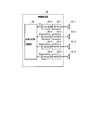
- FIG. 5 shows a configuration example of a conventional radio base station.
- the wireless base station 50 includes a plurality (here, four) of antennas 51-1 to 51-4, a plurality of RF units 52-1 to 52-4, and a plurality of ADC units 53-1 to 53-4. , MIMO-OFDM demodulation unit 54. It should be noted that functional blocks that are generally installed in a wireless base station are omitted.
- the MIMO-OFDM signals received by the antennas 51-1 to 51-4 are input to the RF units 52-1 to 52-4, respectively.
- the RF units 52-1 to 52-4 perform analog processing such as amplification, frequency change, and filtering on the MIMO-OFDM signals input from the antennas 51-1 to 51-4, and convert the converted signals into ADC signals. Output to the units 53-1 to 53-4.
- the RF unit here is assumed to be equipped with the function of the RF front end of a general wireless device.
- the ADC units 53-1 to 53-4 convert analog signals corresponding to the respective antenna characteristics input from the RF units 52-1 to 52-4 into digital signals, and the digital signals are parallelized to the MIMO-OFDM demodulation unit 54.
- the MIMO-OFDM demodulation unit 54 performs a MIMO-OFDM demodulation process defined by a wireless LAN system or the like on the digital signals D1 to D4 input in parallel according to each antenna characteristic.
- the RF characteristic and the ADC portion are shared by periodically switching the antenna characteristics in synchronization with the sampling cycle of reception. It is an object of the present invention to provide a wireless base station and a wireless base station receiving method that can be realized.
- a first aspect of the present invention is, in a radio base station that receives an uplink multi-user MIMO signal based on OFDM modulation, a characteristic variable antenna capable of selecting or switching antenna characteristics according to a predetermined periodic variable timing, and a characteristic variable antenna.
- the RF unit that performs reception processing on the received signal and outputs the reception-processed analog signal, and the analog signal input from the RF unit is sampled at a sampling period corresponding to the variable timing of the antenna characteristics of the variable characteristic antenna,
- An ADC unit for converting and outputting the digital signal, a signal dividing unit for dividing and outputting the digital signal input from the ADC unit as a digital signal for each antenna characteristic, and the digital signal divided by the signal dividing unit are input, and a predetermined signal is input.
- a MIMO-OFDM demodulation unit that performs a MIMO-OFDM demodulation process, and an AD In accordance with the sampling period of the part, and a control unit providing the antenna characteristic of the characteristic variable antenna a predetermined variable timing cyclically selected or switched to the characteristic variable antenna.
- the variable characteristic antenna includes a plurality of antenna elements each having different antenna characteristics, and a switch that selects one of the plurality of antenna elements according to a predetermined variable timing.
- the variable characteristic antenna combines a plurality of antenna elements having different antenna characteristics and outputs of the plurality of antenna elements in different combinations according to predetermined variable timing, and And a synthesizing unit for switching between.
- variable characteristic antenna includes one power feeding antenna element, and movable means for switching, or moving or vibrating or rotating the power feeding antenna element at a speed according to a predetermined variable timing to switch the antenna characteristic. Equipped with.
- the variable characteristic antenna has a fixed feeding antenna element, at least one parasitic antenna element or reflector, and a parasitic antenna element or reflector at a speed corresponding to a predetermined variable timing.
- a second aspect of the present invention is a radio base station receiving method for receiving an uplink multi-user MIMO signal by OFDM modulation, wherein an uplink is provided by a variable characteristic antenna whose antenna characteristic can be selected or switched according to a predetermined periodic variable timing.
- the multi-user MIMO signal is received, the RF unit performs reception processing on the signal received by the variable characteristic antenna, outputs the reception-processed analog signal, and the ADC unit changes the characteristic of the analog signal input from the RF unit.
- Sampling is performed at a sampling period corresponding to the variable timing of the antenna characteristics of the antenna, converted into a digital signal and output, and the signal division unit divides the digital signal input from the ADC unit as a digital signal for each antenna characteristic and outputs the digital signal.
- the MIMO-OFDM demodulator receives the digital signal divided by the signal divider. And performs demodulation processing of a given MIMO-OFDM, the control unit, in accordance with the sampling period of the ADC unit, giving the antenna characteristics of the characteristic variable antenna a predetermined variable timing cyclically selected or switched to the characteristic variable antenna.
- the radio base station in an environment in which a radio base station using OFDM modulation receives signals from a plurality of radio terminal stations by MIMO, the radio base station periodically changes antenna characteristics in synchronization with a sampling cycle of reception, and the antenna
- cost and power consumption can be reduced by sharing the RF part and the ADC.
- FIG. 1 shows a configuration example of a wireless base station and a wireless terminal station in the present invention.
- the wireless base station 10 includes a variable characteristic antenna 11, an RF unit 12, an ADC unit 13, a signal division unit 14, a MIMO-OFDM demodulation unit 15, and a control unit 16. Note that functional blocks that are generally installed in a base station are omitted.
- the variable characteristic antenna 11 is an antenna that periodically switches antenna characteristics (directivity, output, phase, etc.) according to a control signal input from the control unit 16. For example, it corresponds to the configuration in which one of the conventional antennas 51-1 to 51-4 shown in FIG. 5 is periodically switched by the switch SW. Other examples of the variable characteristic antenna 11 will be described later.
- the signal received by the variable characteristic antenna 11 is output to one RF unit 12.
- the RF unit 12 performs processing such as amplification, frequency change, and filtering on the signal input from the variable characteristic antenna 11, and outputs the processed signal to the ADC unit 13. That is, it is a function of an RF front end of a general wireless device.
- the ADC unit 13 changes the analog signal input from the RF unit 12 into a digital signal and outputs the digital signal to the signal division unit 14. Also, the sampling cycle of the ADC section is notified to the control section 16.
- the signal division unit 14 divides the signal input from the ADC unit 13 in synchronization with the sampling period and outputs the signal to the MIMO-OFDM demodulation unit 15.
- the MIMO-OFDM demodulation unit 15 performs the MIMO-OFDM demodulation process defined by the wireless LAN system or the like on the signal divided by the signal division unit 14.
- the ADC unit 13 has the conventional ADC unit 53 shown in FIG.
- the sampling period is set to four times, and the signals D1 to D4 corresponding to each antenna characteristic are output in a time division manner.
- the control unit 16 selects one of the four antennas in the sampling cycle of the ADC unit 13 to switch the antenna characteristic.
- the signal division unit 14 divides the signals D1 to D4 corresponding to each antenna characteristic in this sampling period and outputs the signals to the MIMO-OFDM demodulation unit 15. As a result, the signals D1 to D4 having the same antenna characteristics are periodically output to the four output ports of the signal division unit 14.
- the ADC unit 13 may perform oversampling to perform finer sampling and generate a signal with a smaller period by combining these signals.
- a plurality of antennas may be selected at the same time by the switch SW of the variable characteristic antenna 11 and the combined signal may be output to the RF unit 12.
- the wireless terminal stations 20-1 and 20-2 are composed of a MIMO-OFDM modulation unit 21, a DAC unit 22, an RF unit 23, and an antenna 24, and are the same as the conventional configuration. Note that functional blocks that are generally installed in a terminal station are omitted.
- the MIMO-OFDM modulation unit 21 performs MIMO-OFDM modulation processing specified by a wireless LAN system or the like, and outputs a modulated signal to the DAC unit 22.
- the DAC unit 22 changes the digital signal input from the MIMO-OFDM unit 21 into an analog signal and outputs it to the RF unit 23.
- the RF unit 23 performs processing such as amplification, frequency change, and filtering on the signal input from the DAC unit 22 and outputs the processed signal to the antenna 24. That is, the RF unit 23 is a function of an RF front end of a general wireless device.
- the antenna 24 radiates the signal input from the RF unit 23 into the air.
- FIG. 2 shows an example of a sequence of uplink multi-user MIMO transmission according to the present invention.
- the wireless base station 10 transmits a trigger signal to the wireless terminal stations 20-1 and 20-2 to perform uplink multi-user MIMO transmission.
- the trigger signal is a signal for synchronizing transmission timing, transmission power, frequency, etc. between wireless terminal stations, and is a frame defined by IEEE 802.11ax of the wireless LAN standard. Further, the trigger signal is transmitted with a predetermined antenna characteristic of the characteristic variable antenna 11 of the radio base station 10, and the antenna characteristic is not changed during the transmission of the trigger signal.
- the wireless terminal stations 20-1 and 20-2 which have received the trigger signal, generate an OFDM signal for uplink multi-user MIMO transmission according to the trigger signal, in synchronization with various parameters, and generate the OFDM signal.
- the radio base station 10 receives an OFDM signal for uplink multi-user MIMO transmission while periodically switching the antenna characteristic of the characteristic variable antenna 11. It is confirmed whether or not the received signal has an error, and the result is transmitted to the wireless terminal stations 20-1 and 20-2 with a predetermined antenna characteristic by a response confirmation signal.
- the trigger signal and the response confirmation signal may be transmitted by selecting and fixing one of the four antennas of the variable characteristic antenna 11, or by using a dedicated antenna having a predetermined antenna characteristic. Good.
- FIG. 3 shows another configuration example of the variable characteristic antenna 11.
- the variable characteristic antenna 11 shown in FIG. 3A has a configuration in which signals received by a plurality of antennas are combined by the combining unit 111 and output to the RF unit 12.
- the antenna characteristics are switched depending on the combination of antennas to be combined. For example, if there are four antennas, six antenna characteristics can be obtained by combining two antennas, so that a total of ten antenna characteristics including the antenna characteristics of one antenna can be obtained. This can be dealt with by increasing the sampling cycle of the ADC unit 13 to 10 times that of the conventional one. Further, a configuration may be adopted in which a weight is multiplied by using a phase shifter or an attenuator for each antenna.
- the variable-characteristic antenna 11 of FIG. 3 (2) has a configuration in which the antenna characteristics are variable by moving (vibrating) or rotating one feeding antenna element 112 at high speed under the control of the control unit 16.
- the feeding antenna element 112 can be moved (vibrated) by a configuration in which it rotates on a circular rail or a configuration in which it reciprocates on a linear rail.
- the feeding antenna element 112 can be rotated by using a rotary joint.
- one or more parasitic antenna elements 114 are arranged around the fixed feeding antenna element 113, and the parasitic antenna element 114 is moved at high speed under the control of the control unit 16.
- the antenna characteristics are variable by (vibration) or rotation.
- the method of moving (vibrating) or rotating the parasitic antenna element 114 is the same as in the case of FIG. 3 (2).
- a reflector may be used instead of the parasitic antenna element 114.
- the reflector may have a complicated surface in order to change the antenna characteristics. Further, the antenna characteristic may be changed by changing the capacitance connected to the parasitic antenna element 114.
- FIG. 4 shows another configuration example of the radio base station according to the present invention.
- two sets of the characteristic variable antenna 11 shown in FIG. 1, the RF unit 12, the ADC unit 13, and the signal division unit 14 of the radio base station 10 are provided, and the output of each signal division unit 14 is a MIMO-OFDM demodulation unit 15. It is a configuration to input to.
- the antennas of the two sets of variable characteristic antennas 11 are common, and the control unit 16 controls so that the antennas selected by the switches SW1 and SW2 are different.
- variable characteristic antenna 11 using the combining unit 111 shown in FIG. 3 (1) can be configured in the same manner, and the combination of the combined antennas is controlled so as to be different.
- radio base station 11 variable characteristic antenna 12 RF section 13 ADC section 14 signal division section 15 MIMO-OFDM demodulation section 16 control section 20 radio terminal station 21 MIMO-OFDM modulation section 22 DAC section 23 RF section 24 antenna 111 combining section 112, 113 Feed Antenna Element 114 Parasitic Antenna Element
Landscapes
- Engineering & Computer Science (AREA)
- Computer Networks & Wireless Communication (AREA)
- Signal Processing (AREA)
- Power Engineering (AREA)
- Radio Transmission System (AREA)
- Mobile Radio Communication Systems (AREA)
- Variable-Direction Aerials And Aerial Arrays (AREA)
- Transceivers (AREA)
Abstract
所定の周期的な可変タイミングに応じてアンテナ特性の選択または切り替えが可能な特性可変アンテナと、特性可変アンテナに受信した信号に対して受信処理を行うRF部と、RF部から入力するアナログ信号を特性可変アンテナのアンテナ特性の可変タイミングに対応するサンプリング周期でサンプリングするADC部と、ADC部から入力するデジタル信号をアンテナ特性ごとのデジタル信号として分割し出力する信号分割部と、信号分割部で分割したデジタル信号を入力し、所定のMIMO-OFDMの復調処理を行うMIMO-OFDM復調部と、ADC部のサンプリング周期に応じて、特性可変アンテナのアンテナ特性を周期的に選択または切り替える制御部とを備える。
Description
本発明は、複数の無線端末局から送信されるMIMO-OFDM信号を受信する無線基地局において、複数のアンテナに対するRF部およびADC部を共用化する無線基地局および無線基地局受信方法に関する。
5GHz帯の電波を用いた高速無線アクセスシステムとして、IEEE802.11a規格、IEEE802.11n規格、IEEE802.11ac規格(以下、11a規格、11n規格、11ac規格という)に基づく無線LANがある。11a規格では、直交周波数分割多重(OFDM:Orthogonal Frequency Division Multiplexing )変調方式をベースとして、マルチパスフェージング環境での特性を安定化させて、最大54Mbit/s の伝送速度を実現している。さらに、11n規格では、複数のアンテナを用いて同一の無線チャネルで空間分割多重を行うMIMO(Multiple Input Multiple Output)や、20MHzの周波数チャネルを2つ同時に利用して40MHzの周波数チャネルを利用するチャネルボンディング技術を用いて、最大 600Mbit/s の伝送速度を実現している。
また、11acの規格(非特許文献1)では、20MHzの周波数チャネルを8つまで同時に利用し、最大 160MHzの周波数チャネルとして利用するチャネルボンディング技術や、同一の無線チャネルで複数の宛先に対して異なる信号を同時伝送する下り回線のマルチユーザMIMO技術等を利用し、11n規格より高速かつ高効率な無線通信を実現している。
現在では、伝送速度の向上に加えて伝送効率の向上にも焦点を当てたIEEE802.11ax規格(以下、11ax規格という)の策定も進められている。11ax規格では、同時伝送による空間的な周波数再利用の促進、OFDM変調方式の効率改善、また、マルチユーザ伝送として、上下回線のOFDMA伝送と上り回線のマルチユーザMIMO伝送が追加される予定である。
IEEE Std 802.11ac-2013, Dec. 2013
図5は、従来の無線基地局の構成例を示す。
図5において、無線基地局50は、複数(ここでは4本)のアンテナ51-1~51-4、複数のRF部52-1~52-4、複数のADC部53-1~53-4、MIMO-OFDM復調部54により構成される。なお、一般的に無線基地局に搭載される機能ブロックについては省略している。
図5において、無線基地局50は、複数(ここでは4本)のアンテナ51-1~51-4、複数のRF部52-1~52-4、複数のADC部53-1~53-4、MIMO-OFDM復調部54により構成される。なお、一般的に無線基地局に搭載される機能ブロックについては省略している。
アンテナ51-1~51-4で受信したMIMO-OFDM信号は、それぞれRF部52-1~52-4に入力する。RF部52-1~52-4は、アンテナ51-1~51-4からそれぞれ入力するMIMO-OFDM信号に対して、増幅・周波数変更・フィルタリングなどのアナログ処理を施し、変換した信号をそれぞれADC部53-1~53-4に出力する。ここでのRF部は、一般的な無線装置のRFフロントエンドの機能が搭載されることを想定する。ADC部53-1~53-4は、RF部52-1~52-4から入力する各アンテナ特性に対応するアナログ信号をデジタル信号に変換し、そのデジタル信号を並列にMIMO-OFDM復調部54に出力する。MIMO-OFDM復調部54は、各アンテナ特性に応じて並列に入力するデジタル信号D1~D4に対して、無線LANシステム等で規定されるMIMO-OFDMの復調処理を行う。
このように、これまでの無線基地局では、受信信号に対してMIMO-OFDM復調を行うためには、アンテナ数に応じたRF部およびADC部を設置する必要があった。さらに、近年の5Gなどの無線通信システムでは、マッシブMIMO伝送のようにアンテナ数の増大が飛躍的に進んでいるため、RF部およびADC部の増加に伴うコストおよび消費電力の増加に関する課題を解決することが求められている。
本発明は、複数の無線端末局から送信されるMIMO-OFDM信号を受信する無線基地局において、受信のサンプリング周期に同期してアンテナ特性を周期的に切り替えることにより、RF部およびADC部を共用化することができる無線基地局および無線基地局受信方法を提供することを目的とする。
第1の発明は、OFDM変調による上り回線マルチユーザMIMO信号を受信する無線基地局において、所定の周期的な可変タイミングに応じてアンテナ特性の選択または切り替えが可能な特性可変アンテナと、特性可変アンテナに受信した信号に対して受信処理を行い、受信処理したアナログ信号を出力するRF部と、RF部から入力するアナログ信号を特性可変アンテナのアンテナ特性の可変タイミングに対応するサンプリング周期でサンプリングし、デジタル信号に変換して出力するADC部と、ADC部から入力するデジタル信号をアンテナ特性ごとのデジタル信号として分割し出力する信号分割部と、信号分割部で分割したデジタル信号を入力し、所定のMIMO-OFDMの復調処理を行うMIMO-OFDM復調部と、ADC部のサンプリング周期に応じて、特性可変アンテナのアンテナ特性を周期的に選択または切り替える所定の可変タイミングを特性可変アンテナに与える制御部とを備える。
第1の発明の無線基地局において、特性可変アンテナは、それぞれ異なるアンテナ特性をもつ複数のアンテナ素子と、複数のアンテナ素子の1つを所定の可変タイミングに応じて選択するスイッチとを備える。
第1の発明の無線基地局において、特性可変アンテナは、それぞれ異なるアンテナ特性をもつ複数のアンテナ素子と、複数のアンテナ素子の出力を所定の可変タイミングに応じてそれぞれ異なる組合せで合成し、アンテナ特性を切り替える合成部とを備える。
第1の発明の無線基地局において、特性可変アンテナは、1本の給電アンテナ素子と、給電アンテナ素子を所定の可変タイミングに応じた速度で移動または振動または回転させてアンテナ特性を切り替える可動手段とを備える。
第1の発明の無線基地局において、特性可変アンテナは、固定の給電アンテナ素子と、少なくとも1つの無給電アンテナ素子または反射板と、無給電アンテナ素子または反射板を所定の可変タイミングに応じた速度で移動または振動または回転させてアンテナ特性を切り替える可動手段とを備える。
第2の発明は、OFDM変調による上り回線マルチユーザMIMO信号を受信する無線基地局受信方法において、所定の周期的な可変タイミングに応じてアンテナ特性の選択または切り替えが可能な特性可変アンテナで上り回線マルチユーザMIMO信号を受信し、RF部で、特性可変アンテナに受信した信号に対して受信処理を行い、受信処理したアナログ信号を出力し、ADC部で、RF部から入力するアナログ信号を特性可変アンテナのアンテナ特性の可変タイミングに対応するサンプリング周期でサンプリングし、デジタル信号に変換して出力し、信号分割部で、ADC部から入力するデジタル信号をアンテナ特性ごとのデジタル信号として分割して出力し、MIMO-OFDM復調部で、信号分割部で分割したデジタル信号を入力し、所定のMIMO-OFDMの復調処理を行い、制御部で、ADC部のサンプリング周期に応じて、特性可変アンテナのアンテナ特性を周期的に選択または切り替える所定の可変タイミングを特性可変アンテナに与える。
本発明は、OFDM変調を用いる無線基地局が複数の無線端末局からの信号をMIMO受信する環境において、無線基地局は受信のサンプリング周期に同期してアンテナ特性を周期的に変化させ、当該アンテナで取得したデータを同一のアンテナ特性ごとに分割し、その受信信号を異なる信号としてMIMO-OFDM受信することで、RF部およびADCの共用化によるコストおよび消費電力の低減が可能となる
図1は、本発明における無線基地局および無線端末局の構成例を示す。
図1において、無線基地局10と無線通信可能な範囲であるサービスエリア内に2以上の無線端末局20-1,20-2が存在する。
図1において、無線基地局10と無線通信可能な範囲であるサービスエリア内に2以上の無線端末局20-1,20-2が存在する。
無線基地局10は、特性可変アンテナ11、RF部12、ADC部13、信号分割部14、MIMO-OFDM復調部15、制御部16により構成される。なお、一般的に基地局に搭載される機能ブロックについては省略している。
特性可変アンテナ11は、制御部16から入力する制御信号に応じてアンテナ特性(指向性・出力・位相など)を周期的に切り替えるアンテナである。例えば、図5に示す従来のアンテナ51-1~51-4の1つをスイッチSWで周期的に切り替える構成に対応する。特性可変アンテナ11のその他の例については後述する。この特性可変アンテナ11で受信した信号を1つのRF部12に出力する。
RF部12は、特性可変アンテナ11から入力した信号に対して、増幅・周波数変更・フィルタリングなどの処理を行い、処理した信号をADC部13に出力される。すなわち、一般的な無線装置のRFフロントエンドの機能である。ADC部13では、RF部12から入力するアナログ信号をデジタル信号に変更し、信号分割部14に出力する。また、ADC部のサンプリング周期を制御部16に通知する。信号分割部14では、ADC部13から入力された信号をサンプリング周期に同期して分割し、MIMO-OFDM復調部15に出力する。MIMO-OFDM復調部15では、信号分割部14で分割した信号について、無線LANシステム等で規定されるMIMO-OFDMの復調処理を行う。
ここで、特性可変アンテナ11において、例えば4本のアンテナの1つを周期的に選択することによりアンテナ特性を周期的に切り替える場合には、ADC部13は、図5に示す従来のADC部53のサンプリング周期の4倍とし、各アンテナ特性に対応する信号D1~D4を時分割で出力する。制御部16は、ADC部13のサンプリング周期で4本のアンテナの1つを選択してアンテナ特性を切り替える。また、信号分割部14は、このサンプリング周期で各アンテナ特性に対応する信号D1~D4を分割してMIMO-OFDM復調部15に出力する。その結果、信号分割部14の4つの出力ポートには、それぞれ同じアンテナ特性の信号D1~D4が周期的に出力される。
なお、ADC部13でオーバーサンプリングすることによって、さらに細かく標本化し、それらの信号の合成によって少ない周期の信号を発生させてもよい。
また、特性可変アンテナ11のスイッチSWにおいて、複数のアンテナを同時に選択してその合成した信号をRF部12に出力してもよい。
無線端末局20-1,20-2は、MIMO-OFDM変調部21、DAC部22、RF部23、アンテナ24により構成され、従来構成と同様である。なお、一般的に端末局に搭載される機能ブロックについては省略している。
MIMO-OFDM変調部21は、無線LANシステム等で規定されるMIMO-OFDMの変調処理を行い、変調信号をDAC部22に出力する。DAC部22は、MIMO-OFDM部21から入力するデジタル信号をアナログ信号に変更し、RF部23に出力する。RF部23は、DAC部22から入力する信号に対して、増幅・周波数変更・フィルタリングなどの処理を行い、処理した信号をアンテナ24に出力する。すなわちRF部23は、一般的な無線装置のRFフロントエンドの機能である。アンテナ24は、RF部23から入力する信号を空中に放射する。
図2は、本発明における上り回線のマルチユーザMIMO伝送のシーケンスの一例を示す。
図2において、無線基地局10は、上り回線のマルチユーザMIMO伝送を行うために、トリガー信号を無線端末局20-1,20-2に送信する。トリガー信号とは、無線端末局同士の送信タイミング・送信電力・周波数などの同期をとるための信号であり、無線LAN規格のIEEE802.11axで規定されるフレームである。また、トリガー信号は、無線基地局10の特性可変アンテナ11の所定のアンテナ特性で送信され、そのアンテナ特性はトリガー信号の送信中に変化させないこととする。
図2において、無線基地局10は、上り回線のマルチユーザMIMO伝送を行うために、トリガー信号を無線端末局20-1,20-2に送信する。トリガー信号とは、無線端末局同士の送信タイミング・送信電力・周波数などの同期をとるための信号であり、無線LAN規格のIEEE802.11axで規定されるフレームである。また、トリガー信号は、無線基地局10の特性可変アンテナ11の所定のアンテナ特性で送信され、そのアンテナ特性はトリガー信号の送信中に変化させないこととする。
次に、トリガー信号を受信した無線端末局20-1,20-2は、トリガー信号に従い、各種パラメータの同期のもと、上り回線のマルチユーザMIMO伝送のOFDM信号を生成して無線基地局10に送信する。一方、無線基地局10は図1の構成により、上り回線のマルチユーザMIMO伝送のOFDM信号を特性可変アンテナ11のアンテナ特性を周期的に切り替えながら受信する。受信した信号について誤りがないかを確認し、その結果を応答確認信号によって無線端末局20-1と20-2に所定のアンテナ特性で送信する。
なお、トリガー信号および応答確認信号は、特性可変アンテナ11の4本のアンテナの1つを選択および固定して送信してもよいし、所定のアンテナ特性を有する専用のアンテナを用いて送信してもよい。
図3は、特性可変アンテナ11の他の構成例を示す。
図3(1) の特性可変アンテナ11は、合成部111で複数のアンテナで受信した信号を合成してRF部12に出力する構成である。アンテナ特性は、合成するアンテナの組合せにより切り替えられる。例えば、4本のアンテナであれば、2本のアンテナの組合せで6通りのアンテナ特性が得られるので、1本のアンテナによるアンテナ特性を含めて合計10通りのアンテナ特性が得られる。ADC部13のサンプリング周期を従来の10倍にすることにより対応可能である。また、各アンテナに移相器やアッテネータを用いてウエイトを乗算する構成としてもよい。
図3(1) の特性可変アンテナ11は、合成部111で複数のアンテナで受信した信号を合成してRF部12に出力する構成である。アンテナ特性は、合成するアンテナの組合せにより切り替えられる。例えば、4本のアンテナであれば、2本のアンテナの組合せで6通りのアンテナ特性が得られるので、1本のアンテナによるアンテナ特性を含めて合計10通りのアンテナ特性が得られる。ADC部13のサンプリング周期を従来の10倍にすることにより対応可能である。また、各アンテナに移相器やアッテネータを用いてウエイトを乗算する構成としてもよい。
図3(2) の特性可変アンテナ11は、1本の給電アンテナ素子112を制御部16の制御により高速に移動(振動)または回転させることにより、アンテナ特性を可変とする構成である。なお、給電アンテナ素子112の移動(振動)は円形のレール上を周回させる構成、または直線のレール上を往復運動させる構成により可能である。給電アンテナ素子112の回転はロータリージョイントを用いることにより可能である。
図3(3) の特性可変アンテナ11は、固定された給電アンテナ素子113の周りに1または複数の無給電アンテナ素子114を配置し、無給電アンテナ素子114を制御部16の制御により高速に移動(振動)または回転させることにより、アンテナ特性を可変とする構成である。無給電アンテナ素子114の移動(振動)または回転の方法は、図3(2) の場合と同様である。また、無給電アンテナ素子114に替えて、反射板を用いてもよい。なお、反射板は、アンテナ特性を変化させるために、反射板を複雑な面で構成してもよい。また、無給電アンテナ素子114に接続される容量を可変させることで、アンテナ特性を可変させる構成としてもよい。
図4は、本発明における無線基地局の他の構成例を示す。
図4において、図1に示す特性可変アンテナ11と、無線基地局10のRF部12、ADC部13、信号分割部14を2セット備え、各信号分割部14の出力をMIMO-OFDM復調部15に入力する構成である。ただし、2セットの特性可変アンテナ11のアンテナは共通であり、制御部16はスイッチSW1,SW2でそれぞれ選択するアンテナが異なるように制御する。
図4において、図1に示す特性可変アンテナ11と、無線基地局10のRF部12、ADC部13、信号分割部14を2セット備え、各信号分割部14の出力をMIMO-OFDM復調部15に入力する構成である。ただし、2セットの特性可変アンテナ11のアンテナは共通であり、制御部16はスイッチSW1,SW2でそれぞれ選択するアンテナが異なるように制御する。
また、図3(1) に示す合成部111を用いた特性可変アンテナ11についても同様に構成することができ、それぞれ合成するアンテナの組合せが異なるように制御する。
10 無線基地局
11 特性可変アンテナ
12 RF部
13 ADC部
14 信号分割部
15 MIMO-OFDM復調部
16 制御部
20 無線端末局
21 MIMO-OFDM変調部
22 DAC部
23 RF部
24 アンテナ
111 合成部
112,113 給電アンテナ素子
114 無給電アンテナ素子
11 特性可変アンテナ
12 RF部
13 ADC部
14 信号分割部
15 MIMO-OFDM復調部
16 制御部
20 無線端末局
21 MIMO-OFDM変調部
22 DAC部
23 RF部
24 アンテナ
111 合成部
112,113 給電アンテナ素子
114 無給電アンテナ素子
Claims (6)
- OFDM変調による上り回線マルチユーザMIMO信号を受信する無線基地局において、
所定の周期的な可変タイミングに応じてアンテナ特性の選択または切り替えが可能な特性可変アンテナと、
前記特性可変アンテナに受信した信号に対して受信処理を行い、受信処理したアナログ信号を出力するRF部と、
前記RF部から入力するアナログ信号を前記特性可変アンテナのアンテナ特性の可変タイミングに対応するサンプリング周期でサンプリングし、デジタル信号に変換して出力するADC部と、
前記ADC部から入力するデジタル信号を前記アンテナ特性ごとのデジタル信号として分割し出力する信号分割部と、
前記信号分割部で分割したデジタル信号を入力し、所定のMIMO-OFDMの復調処理を行うMIMO-OFDM復調部と、
前記ADC部のサンプリング周期に応じて、前記特性可変アンテナのアンテナ特性を周期的に選択または切り替える前記所定の可変タイミングを前記特性可変アンテナに与える制御部と
を備えたことを特徴とする無線基地局。 - 請求項1に記載の無線基地局において、
前記特性可変アンテナは、
それぞれ異なる前記アンテナ特性をもつ複数のアンテナ素子と、
前記複数のアンテナ素子の1つを前記所定の可変タイミングに応じて選択するスイッチと
を備えたことを特徴とする無線基地局。 - 請求項1に記載の無線基地局において、
前記特性可変アンテナは、
それぞれ異なる前記アンテナ特性をもつ複数のアンテナ素子と、
前記複数のアンテナ素子の出力を前記所定の可変タイミングに応じてそれぞれ異なる組合せで合成し、前記アンテナ特性を切り替える合成部と
を備えたことを特徴とする無線基地局。 - 請求項1に記載の無線基地局において、
前記特性可変アンテナは、
1本の給電アンテナ素子と、
前記給電アンテナ素子を前記所定の可変タイミングに応じた速度で移動または振動または回転させて前記アンテナ特性を切り替える可動手段と
を備えたことを特徴とする無線基地局。 - 請求項1に記載の無線基地局において、
前記特性可変アンテナは、
固定の給電アンテナ素子と、
少なくとも1つの無給電アンテナ素子または反射板と、
前記無給電アンテナ素子または反射板を前記所定の可変タイミングに応じた速度で移動または振動または回転させて前記アンテナ特性を切り替える可動手段と
を備えたことを特徴とする無線基地局。 - OFDM変調による上り回線マルチユーザMIMO信号を受信する無線基地局受信方法において、
所定の周期的な可変タイミングに応じてアンテナ特性の選択または切り替えが可能な特性可変アンテナで前記上り回線マルチユーザMIMO信号を受信し、
RF部で、前記特性可変アンテナに受信した信号に対して受信処理を行い、受信処理したアナログ信号を出力し、
ADC部で、前記RF部から入力するアナログ信号を前記特性可変アンテナのアンテナ特性の可変タイミングに対応するサンプリング周期でサンプリングし、デジタル信号に変換して出力し、
信号分割部で、前記ADC部から入力するデジタル信号を前記アンテナ特性ごとのデジタル信号として分割して出力し、
MIMO-OFDM復調部で、前記信号分割部で分割したデジタル信号を入力し、所定のMIMO-OFDMの復調処理を行い、
制御部で、前記ADC部のサンプリング周期に応じて、前記特性可変アンテナのアンテナ特性を周期的に選択または切り替える前記所定の可変タイミングを前記特性可変アンテナに与える
ことを特徴とする無線基地局受信方法。
Priority Applications (1)
| Application Number | Priority Date | Filing Date | Title |
|---|---|---|---|
| US17/278,693 US11804881B2 (en) | 2018-10-25 | 2019-10-18 | Radio base station and reception method at radio base station |
Applications Claiming Priority (2)
| Application Number | Priority Date | Filing Date | Title |
|---|---|---|---|
| JP2018201282A JP7219587B2 (ja) | 2018-10-25 | 2018-10-25 | 無線基地局および無線基地局受信方法 |
| JP2018-201282 | 2018-10-25 |
Publications (1)
| Publication Number | Publication Date |
|---|---|
| WO2020085255A1 true WO2020085255A1 (ja) | 2020-04-30 |
Family
ID=70331332
Family Applications (1)
| Application Number | Title | Priority Date | Filing Date |
|---|---|---|---|
| PCT/JP2019/041195 Ceased WO2020085255A1 (ja) | 2018-10-25 | 2019-10-18 | 無線基地局および無線基地局受信方法 |
Country Status (3)
| Country | Link |
|---|---|
| US (1) | US11804881B2 (ja) |
| JP (1) | JP7219587B2 (ja) |
| WO (1) | WO2020085255A1 (ja) |
Cited By (1)
| Publication number | Priority date | Publication date | Assignee | Title |
|---|---|---|---|---|
| WO2025134230A1 (ja) * | 2023-12-19 | 2025-06-26 | 日本電信電話株式会社 | 無線通信システム、受信局、無線通信方法および無線通信用プログラム |
Families Citing this family (3)
| Publication number | Priority date | Publication date | Assignee | Title |
|---|---|---|---|---|
| JP7164810B2 (ja) * | 2018-09-06 | 2022-11-02 | 日本電信電話株式会社 | 信号処理装置及び光受信器 |
| WO2022123629A1 (ja) * | 2020-12-07 | 2022-06-16 | 日本電信電話株式会社 | 受信装置、及び受信方法 |
| JP7677079B2 (ja) * | 2021-09-01 | 2025-05-15 | 日本電信電話株式会社 | 受信装置、及び受信方法 |
Citations (4)
| Publication number | Priority date | Publication date | Assignee | Title |
|---|---|---|---|---|
| JP2005328505A (ja) * | 2004-04-16 | 2005-11-24 | Matsushita Electric Ind Co Ltd | ダイバーシティ受信機 |
| JP2009081578A (ja) * | 2007-09-25 | 2009-04-16 | Samsung Electronics Co Ltd | 受信装置 |
| JP2013533681A (ja) * | 2010-06-07 | 2013-08-22 | エントロピック・コミュニケーションズ・インコーポレイテッド | 受信器およびアンテナアレイ構成要素でのリアルタイム多重化のための方法および機器 |
| JP2015043550A (ja) * | 2013-08-26 | 2015-03-05 | 日本電信電話株式会社 | 無線通信システム及びアンテナ装置 |
Family Cites Families (5)
| Publication number | Priority date | Publication date | Assignee | Title |
|---|---|---|---|---|
| CN100385826C (zh) * | 2002-06-24 | 2008-04-30 | 美国博通公司 | 采用多路复用接收链处理的降低复杂度的天线系统 |
| US7860182B2 (en) * | 2004-09-23 | 2010-12-28 | Interdigital Technology Corporation | Receiver hardware reduction for spatially independent signals and associated methods |
| JP2007300383A (ja) * | 2006-04-28 | 2007-11-15 | Fujitsu Ltd | Mimo−ofdm送信機 |
| US8683284B2 (en) | 2007-09-25 | 2014-03-25 | Samsung Electronics Co., Ltd. | Receiving apparatus and method |
| KR102614380B1 (ko) * | 2017-02-08 | 2023-12-15 | 한국전자통신연구원 | 단일 rf 체인 안테나를 이용한 통신 방법 및 장치 |
-
2018
- 2018-10-25 JP JP2018201282A patent/JP7219587B2/ja active Active
-
2019
- 2019-10-18 WO PCT/JP2019/041195 patent/WO2020085255A1/ja not_active Ceased
- 2019-10-18 US US17/278,693 patent/US11804881B2/en active Active
Patent Citations (4)
| Publication number | Priority date | Publication date | Assignee | Title |
|---|---|---|---|---|
| JP2005328505A (ja) * | 2004-04-16 | 2005-11-24 | Matsushita Electric Ind Co Ltd | ダイバーシティ受信機 |
| JP2009081578A (ja) * | 2007-09-25 | 2009-04-16 | Samsung Electronics Co Ltd | 受信装置 |
| JP2013533681A (ja) * | 2010-06-07 | 2013-08-22 | エントロピック・コミュニケーションズ・インコーポレイテッド | 受信器およびアンテナアレイ構成要素でのリアルタイム多重化のための方法および機器 |
| JP2015043550A (ja) * | 2013-08-26 | 2015-03-05 | 日本電信電話株式会社 | 無線通信システム及びアンテナ装置 |
Cited By (1)
| Publication number | Priority date | Publication date | Assignee | Title |
|---|---|---|---|---|
| WO2025134230A1 (ja) * | 2023-12-19 | 2025-06-26 | 日本電信電話株式会社 | 無線通信システム、受信局、無線通信方法および無線通信用プログラム |
Also Published As
| Publication number | Publication date |
|---|---|
| US20220038141A1 (en) | 2022-02-03 |
| JP7219587B2 (ja) | 2023-02-08 |
| US11804881B2 (en) | 2023-10-31 |
| JP2020068494A (ja) | 2020-04-30 |
Similar Documents
| Publication | Publication Date | Title |
|---|---|---|
| US11044663B2 (en) | Transmitter for transmitting discovery signals, a receiver and methods therein | |
| WO2020085255A1 (ja) | 無線基地局および無線基地局受信方法 | |
| CN107078769B (zh) | 用于使用多个频率的波束选择的系统和方法 | |
| JP4921567B2 (ja) | 複数無線機の通信装置及びその方法 | |
| KR100931908B1 (ko) | 다중 안테나 시스템의 정보 통신 방법 및 그 시스템 | |
| CN107820682B (zh) | 无线通信网络中的方法和节点 | |
| CN110168958A (zh) | 波束扫描配置 | |
| CN113841353A (zh) | 用于多波束扫描的方法和设备 | |
| JPH11205026A (ja) | 適応可変指向性アンテナ | |
| US8781407B2 (en) | Antenna equipment including the grouping of antenna elements according to communication types | |
| WO2012103853A2 (zh) | 接收和发送信号的方法、发射机、接收机及其系统 | |
| EP3510832B1 (en) | Resource configuration of wireless devices | |
| US10951445B2 (en) | Radio frequency integrated circuit supporting carrier aggregation and wireless communication device including the same | |
| Pisek et al. | High throughput millimeter-wave MIMO beamforming system for short range communication | |
| JP2008295003A (ja) | 多重入力出力の無線伝送システム及びその伝送方法 | |
| JP2012500599A (ja) | 高スループットモデムのためのマルチチャネルアーキテクチャ | |
| JP4545534B2 (ja) | 無線受信装置 | |
| JP7144808B2 (ja) | 無線通信装置及び無線通信方法 | |
| JP7415687B2 (ja) | 無線通信装置及び無線通信方法 | |
| JP6851596B2 (ja) | 無線基地局および無線基地局の制御方法 | |
| US20220294465A1 (en) | Methods and devices for reducing power consumption and increasing frequency of operations in digital to analog converters | |
| JP2024155490A (ja) | 受信装置および受信方法 | |
| JP2006067195A (ja) | Ofdm受信装置及びofdm受信方法 | |
| JP5465609B2 (ja) | ダイバーシチ通信システム | |
| JP2004274604A (ja) | Ofdm受信装置 |
Legal Events
| Date | Code | Title | Description |
|---|---|---|---|
| 121 | Ep: the epo has been informed by wipo that ep was designated in this application |
Ref document number: 19875643 Country of ref document: EP Kind code of ref document: A1 |
|
| NENP | Non-entry into the national phase |
Ref country code: DE |
|
| 122 | Ep: pct application non-entry in european phase |
Ref document number: 19875643 Country of ref document: EP Kind code of ref document: A1 |