WO2020084839A1 - センサデータ圧縮システム、センサ端末、モデル構築装置、およびプログラム - Google Patents
センサデータ圧縮システム、センサ端末、モデル構築装置、およびプログラム Download PDFInfo
- Publication number
- WO2020084839A1 WO2020084839A1 PCT/JP2019/026706 JP2019026706W WO2020084839A1 WO 2020084839 A1 WO2020084839 A1 WO 2020084839A1 JP 2019026706 W JP2019026706 W JP 2019026706W WO 2020084839 A1 WO2020084839 A1 WO 2020084839A1
- Authority
- WO
- WIPO (PCT)
- Prior art keywords
- compression ratio
- sensor data
- data
- sensor
- model
- Prior art date
- Legal status (The legal status is an assumption and is not a legal conclusion. Google has not performed a legal analysis and makes no representation as to the accuracy of the status listed.)
- Ceased
Links
Images




Classifications
-
- H—ELECTRICITY
- H03—ELECTRONIC CIRCUITRY
- H03M—CODING; DECODING; CODE CONVERSION IN GENERAL
- H03M7/00—Conversion of a code where information is represented by a given sequence or number of digits to a code where the same, similar or subset of information is represented by a different sequence or number of digits
- H03M7/30—Compression; Expansion; Suppression of unnecessary data, e.g. redundancy reduction
Definitions
- the present invention relates to a sensor data compression system, a sensor terminal, a model building device, and a program.
- Patent Document 1 discloses information processing provided separately from the sensor terminal in order to dynamically optimize compression coding of sensor data transmitted from the sensor terminal to the server.
- a technique is disclosed in which compression encoding information is generated based on statistical information of data restored from compressed data by an apparatus and the compression encoding information is used in a sensor terminal.
- Patent Document 1 does not describe optimization of the compression ratio, and optimization of the compression ratio using a mathematical model and dynamic optimization of the optimal compression ratio on the sensor terminal side having low calculation capability The method of setting is also not discussed.
- the present invention has been made in view of the above, and an object of the present invention is to provide a new and improved sensor that can achieve both maintenance of data analysis accuracy and reduction of communication cost. It is to provide a data compression system, a sensor terminal, a model building device, and a program.
- the data analysis accuracy is the degree to which a data analysis result with a small error can be obtained without reducing the amount of information required for analysis according to the purpose.
- a sensor that acquires sensor data, and a mathematical model that acquires a compression ratio related to compressed sensing based on a characteristic amount of the acquired sensor data is used.
- a data compression unit that compresses the sensor data at the compression ratio
- a data communication unit that transmits the sensor data compressed by the data compression unit, and the acquired sensor data and was used to build the mathematical model.
- a deviation degree detection unit that detects a deviation degree from sensor data, and the data communication unit models the sensor data that has not been compressed by the compression ratio when the detected deviation degree exceeds a threshold value.
- a sensor data compression system is provided.
- the mathematical model is a compression ratio learning model constructed by using a machine learning method so as to dynamically change the compression ratio for the sensor data with an evaluation index including a restoration error and the compression ratio.
- the compression ratio model construction unit reconstructs the compression ratio learning model using the sensor data that has not been compressed by the compression ratio received from the sensor terminal, and the model transmission unit is configured to perform the compression.
- the compression ratio learning model reconstructed by the ratio model construction unit may be transmitted to the sensor terminal.
- the deviation degree detection unit may detect the deviation degree using a deviation degree detection learning model constructed using the sensor data used for constructing the compression ratio learning model.
- the model building device further comprises a deviation degree detection model construction unit that constructs the deviation degree detection learning model using the sensor data that has not been compressed by the compression ratio received from the sensor terminal,
- the model transmission unit may transmit the deviation degree detection learning model constructed by the deviation degree detection model construction unit to the sensor terminal.
- the compression ratio model construction unit may construct the compression ratio learning model using any one of regression learning, unsupervised learning, and reinforcement learning, which are one of supervised learning.
- the compression ratio model construction unit obtains the compression ratio for optimizing the evaluation index, and learns the compression ratio by regression learning with the sensor data as an explanatory variable and an optimum compression ratio for the sensor data as an objective variable. You may build a model.
- the compression ratio model construction unit may obtain the compression ratio that optimizes the evaluation index by any of a random search, a grid search, or a hill climbing method.
- the compression ratio model construction unit uses a loss function in which the loss becomes smaller as the data compression efficiency becomes higher, and the compression ratio to be optimized is obtained by unsupervised learning that is obtained by updating the parameters of the neural network by the error back propagation method.
- the compression ratio learning model may be constructed.
- the compression ratio model construction unit may construct the compression ratio learning model by reinforcement learning with the sensor data as a state, the compression ratio as a behavior, and data compression efficiency as a reward.
- the compression ratio model construction unit may perform the reinforcement learning with the time domain data or the frequency domain data related to the sensor data as a state.
- the compression ratio model construction unit may divide the range of the compression ratio by a natural number N, and perform reinforcement learning with the compression ratio of each representative value as a discrete value action.
- the compression ratio model construction unit may perform reinforcement learning with the compression ratio as a continuous value action.
- the compression ratio model construction unit may perform reinforcement learning with the evaluation index including the compression ratio or the restoration error as a reward.
- a sensor for acquiring sensor data and a mathematical method for acquiring a compression ratio for compressed sensing based on a characteristic amount of the acquired sensor data.
- a data compression unit that compresses the sensor data at the compression ratio
- a data communication unit that transmits the sensor data compressed by the data compression unit, the acquired sensor data and the mathematical model.
- a deviation degree detection unit that detects a deviation degree from the sensor data used for the construction, and the data communication unit, if the detected deviation degree exceeds a threshold value, compression by the compression ratio is performed.
- a sensor terminal is provided, which transmits the sensor data that is not present to a model building device and receives the mathematical model reconstructed using the sensor data.
- the sensor data is compressed using a mathematical model that acquires a compression ratio related to compressed sensing based on a characteristic amount of the acquired sensor data.
- a compression ratio model construction unit that reconstructs the mathematical model using the sensor data, and the compression ratio model.
- the mathematical model reconstructed by the construction unit is transmitted to at least the sensor terminal that has transmitted the sensor data that has not been compressed by the compression ratio among the plurality of sensor terminals connected via the network.
- a model construction device is provided which includes a model transmission unit.
- a computer is provided with a sensor for acquiring sensor data, and a compression ratio related to compressed sensing based on a characteristic amount of the acquired sensor data.
- a data compression unit that compresses the sensor data at the compression ratio
- a data communication unit that transmits the sensor data compressed by the data compression unit, the acquired sensor data and the A deviation degree detection unit that detects a deviation degree from the sensor data used for the construction of the mathematical model, and the data communication unit, when the detected deviation degree exceeds a threshold value, compression by the compression ratio is performed.
- a sensor terminal which transmits the sensor data that has not been performed to the model building device, and receives the mathematical model reconstructed using the sensor data, Program for operating Te is provided.
- the computer the sensor data using a mathematical model to obtain a compression ratio according to the compression sensing based on the characteristic amount of the acquired sensor data.
- a compression ratio model construction unit that reconstructs the mathematical model using the sensor data.
- the mathematical model reconstructed by the compression ratio model construction unit is a sensor terminal that has transmitted the sensor data that has not been compressed by at least the compression ratio.
- a model transmitting unit for transmitting the model to the model building apparatus.
- FIG. 1 shows the assumption environment to which the sensor data compression system which concerns on one Embodiment of this invention can be applied. It is a block diagram showing an example of composition of a sensor data compression system concerning the embodiment. It is a block diagram showing an example of composition of a sensor terminal for learning concerning the embodiment. It is a block diagram showing an example of composition of a sensor terminal concerning the embodiment. It is a block diagram which shows the structural example of the data receiver which concerns on the same embodiment. It is a flow chart which shows a flow of processing of a sensor terminal for learning concerning the embodiment. It is a figure which shows the outline of the compression ratio learning model construction by regression learning which concerns on the same embodiment. It is an example of sensor data to be compressed according to the same embodiment. FIG.
- FIG. 9 is an enlarged view of sensor data in a period A of FIG. 8 according to the same embodiment.
- FIG. 9 is an enlarged view of sensor data in a period B of FIG. 8 according to the same embodiment.
- FIG. 9 is a diagram showing the relationship between the compression ratio and the data size after compression for each sensor data in period A and period B of FIG. 8 according to the same embodiment.
- FIG. 9 is a diagram showing a relationship between a compression ratio and a restoration error rate for each sensor data in period A and period B of FIG. 8 according to the same embodiment. It is a figure which shows the relationship of the compression ratio and data compression efficiency which concern on each sensor data in period A and period B of FIG. 8 which concerns on the same embodiment.
- FIG. 9 is a diagram showing the relationship between the compression ratio and data compression efficiency which concern on each sensor data in period A and period B of FIG. 8 which concerns on the same embodiment.
- FIG. 9 is a diagram showing a comparison between a calculated value of an optimum compression ratio for the sensor data shown in FIG. 8 according to the same embodiment and an optimum compression ratio estimated by a compression ratio learning model constructed by regression learning. It is a figure which shows the outline
- the present invention relates to vibration data, video data, audio data, etc., in which the degree of sparseness (the property of having many 0 components), which is an index indicating the amount of information of sensor data (hereinafter, may be simply referred to as data), changes.
- the degree of sparseness refers to the minimum data size required to reproduce the original data with respect to the original data size.
- data having the same data size can be said to have a higher sparseness as the amount of information included in the data is higher, and a lower sparseness as the amount of information included in the data is smaller.
- an edge terminal that transmits sensor data that is, a sensor terminal generally has a large restriction on memory capacity, storage capacity, calculation capacity, and the like.
- the network band is greatly restricted. Since there is a trade-off relationship between the amount of data information and the waste of resources in this way, the data transmission amount is reduced while the data amount is maintained by efficiently compressing the data on the sensor terminal side. Required to do.
- Patent Document 1 As a method for effectively performing data compression, for example, there is a technique disclosed in Patent Document 1.
- Patent Document 1 it is necessary to provide an information processing device separately from the sensor terminal in order to generate the compression coded information, which increases the system construction cost. Is assumed.
- the sensor data compression system when data with a relatively high sampling frequency or data with a large data transfer amount is transmitted, an edge with a large resource constraint such as calculation capacity or battery capacity is used.
- a large resource constraint such as calculation capacity or battery capacity.
- the sensor terminal according to the embodiment of the present invention realizes control for dynamically changing the optimum compression ratio according to the amount of information of the sensor data by using a mathematical model built in advance. According to the control described above, even an edge-side sensor terminal having a low calculation capability can set an optimum compression ratio with lightweight processing.
- the above-mentioned compression ratio is the ratio of the size of the data after compression to the size of the original data, and the smaller the compression ratio, the smaller the data size after compression.
- the optimum compression ratio may be defined as a compression ratio that can minimize the size of the data to be transmitted while minimizing the loss of the information amount of the data.
- the sensor terminal is a sensor sensor that is not used when the mathematical model is constructed. Detect the divergence of the acquired sensor data, and if the divergence exceeds the threshold value, rebuild the mathematical model using the sensor data with the high divergence to maintain the accuracy of the compression ratio setting. Is one of the features.
- a mathematical model for dynamically dynamically setting an optimum compression ratio according to the amount of information of data is built in advance with a terminal having high calculation capability.
- the above mathematical model is, for example, a compression ratio learning model constructed by using a machine learning method so that the compression ratio for the sensor data is dynamically changed by an evaluation index including the restoration error rate and the compression ratio. It may be.
- the compression ratio learning model constructed as described above is transplanted to an edge-side sensor terminal to operate, so that the compression ratio is sequentially optimized as compared with the case where the sensor terminal side is sequentially performed. It is possible to reduce the calculation cost at the sensor terminal and the overhead of the gateway and control data.
- the compression ratio learning model described above is used to dynamically change the optimum compression ratio according to the data, thereby maintaining the data analysis accuracy and suppressing the communication cost. As a result, data compression with high compression efficiency is possible.
- the estimation accuracy for unknown data generally deteriorates, but in the present embodiment, the degree of deviation between the learned data and the data to be compressed is detected, and the deviation is detected. If the frequency is high, the data is regarded as unknown data, and the learning model of the sensor terminal is updated by re-learning with a terminal having high calculation ability, so that deterioration of the accuracy of estimation of the optimum compression ratio can be prevented.
- Non-Patent Document 1 A compressed sensing technique as described in Non-Patent Document 1 may be used.
- Compressed sensing is a method of reconstructing a high-dimensional signal having sparsity from a small number of observations.
- the calculation cost of the compression process on the transmission side is generally low, but the calculation cost of the decompression process on the reception side is high. Therefore, it can be said that the technique is suitable for data compression by the sensor terminal on the edge side having low calculation capability.
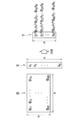
- FIG. 19 is a diagram for explaining an outline of data compression using compressed sensing.
- the original data is defined as X
- the observation matrix for compressing the data is defined as ⁇
- the observation data after compression is defined as Y
- the observation data after compression is expressed by the following formula (1). expressed.
- Non-Patent Document 1 does not discuss the dynamic change of the compression ratio, and does not suggest the adjustment of the compression ratio by changing M. Therefore, the compression sensing according to the present embodiment has an excellent effect as compared with the technique described in Non-Patent Document 1 in that the dynamic compression ratio can be easily set.
- the sensor data compression system compresses sensor data in an environment in which a large number of sensor terminals are installed with the optimum compression ratio set at a low calculation cost on the sensor terminal side, and It is possible to restore data with.
- the compression ratio is an index calculated by (data size before compression) / (data size after compression), and the higher the compression ratio, the smaller the data size after compression.
- the optimization control is not performed sequentially by the sensor terminal on the edge side, but by using a mathematical model that is preliminarily constructed to obtain the optimum compression ratio. .
- the compression ratio may be dynamically changed in the sensor terminal according to the restoration error due to the information amount of the sensor data. For example, when the information amount of data is low, the compression ratio is reduced, and conversely, when the information amount is large, the compression ratio is increased.
- an index of the amount of information for example, the sparsity of data can be mentioned. Even with the same data size, the larger the value of 0, the higher the sparseness, and conversely, the larger the value other than 0, the lower the sparseness. Therefore, by dynamically changing the compression ratio in consideration of the amount of information and the restoration on the restoration side, it is possible to achieve both a high compression ratio of data and a high restoration accuracy.
- the unknown data when unknown data that is not used in the construction of the mathematical model is acquired by the sensor terminal on the edge side, the unknown data is transmitted to a device with high calculation capability, By reconstructing the mathematical model, it is possible to maintain the accuracy of the estimation of the optimum compression ratio.
- the sensor terminal detects the deviation degree from the learned data with respect to the compression target data, and the deviation is detected. Recalculation of unknown data is performed by a device with high calculation ability by regarding highly frequent data as unknown data. Further, the updated learning model is transferred to the sensor terminal, and the sensor terminal estimates the optimum compression ratio, thereby preventing deterioration of accuracy.
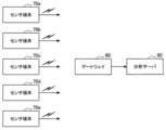
- FIG. 1 is a diagram showing an assumed environment to which the sensor data compression system according to the present embodiment can be applied.
- the sensor data acquired by the plurality of sensor terminals 70a to 70e is transmitted to the gateway 80 via a wireless link, and the data analysis server 90 restores the data via the gateway 80 to perform data analysis.
- the data compression method for example, the above-described compressed sensing is assumed.
- the data analysis server 90 that performs data mining or the like, it is necessary to collect a large amount of data from a plurality of sensor terminals 70a to 70e in order to improve data analysis accuracy.
- the batteries may be wasted in the sensor terminals 70a to 70e, the wireless band may be wasted on the network side, and the storage for accumulating data may be wasted.
- the sensor terminals 70a to 70e may be connected by a low-bandwidth wireless link, it is most effective to reduce the communication cost to perform data compression at the sensor terminals 70a to 70e as the transmission source.
- the compression ratios are dynamically controlled by the sensor terminals 70a to 70e, calculating the optimum compression ratio in real time requires a huge amount of calculation for analytically obtaining sparseness and restoring error. Therefore, it may be difficult due to resource restrictions.
- the optimum compression ratio setting using a mathematical model constructed by using a machine learning method or the like is performed on the sensor terminal side.
- machine learning requires a large amount of computational resources when creating a learning model, but it can be performed with a light process when performing inference using the constructed learning model. Therefore, the terminal that learns the optimum compression ratio may be a terminal that is separate from the sensor terminal that is installed during inference.
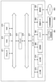
- FIG. 2 is a block diagram showing a configuration example of the sensor data compression system according to the present embodiment.
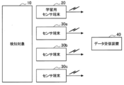
- the sensor data compression system according to the present embodiment includes, for example, as shown in FIG. 2, a learning sensor terminal 20, a plurality of sensor terminals 30a, and a data receiving device 40.
- the learning sensor terminal 20 and the sensor terminal 30 are installed along with the detection target 10.
- the detection target 10 is a target for acquiring various sensor data such as vibrations, images, and sounds.
- the detection target 10 according to the present embodiment may be, for example, various types of equipment installed in a factory, various types of equipment installed in an office, various types of constructions / buildings, and the like.
- the learning sensor terminal 20 constructs a compression ratio learning model (an example of a mathematical model) for obtaining an optimum compression ratio and a deviation degree detection learning model for obtaining a deviation degree between the acquired sensor data and learning data. It is a terminal that does.
- the learning sensor terminal 20 is an example of the model building device according to the present invention.
- the sensor terminal 30 sets the compression ratio for the acquired sensor data by using the compression ratio learning model constructed by the learning sensor terminal 20, and receives the sensor data compressed by using the compression ratio. This is a terminal for transmitting to the device 40. As shown in FIG. 2, a plurality of sensor terminals 30 according to the present embodiment may be installed for a single detection target 10.
- the data receiving device 40 is a device that receives the sensor data compressed by the sensor terminal 30 and restores the sensor data as necessary.
- the data receiving device 40 according to the present embodiment may further have a learning model reconstruction function and a data analysis function described later.
- FIG. 3 is a block diagram showing a configuration example of the learning sensor terminal 20 according to the present embodiment.
- the learning sensor terminal 20 according to the present embodiment includes a sensor 210, an AD conversion unit 220, a data preprocessing unit 230, a compression ratio model construction unit 240, a deviation degree detection model construction unit 250, and model transmission.
- the unit 260 is provided.
- the sensor 210 may be various sensors such as a vibration sensor, a strain sensor, an acoustic sensor, and an image sensor.
- the AD conversion unit 220 performs analog / digital conversion when the sensor data acquired by the sensor 210 is an analog signal.
- the data preprocessing unit 230 performs noise conversion filtering, measurement value conversion, and frequency conversion processing such as FFT (Fast Fourier Transform) on the sensor data converted into a digital signal. .
- FFT Fast Fourier Transform
- the compression ratio model construction unit 240 constructs a mathematical model that acquires the compression ratio for compressed sensing based on the feature amount of the input sensor data.
- the mathematical model described above may be, for example, a learning model constructed by a machine learning method.
- the compression ratio model construction unit 240 according to the present embodiment uses, for example, one of supervised learning as a compression ratio learning model that dynamically changes the compression ratio for sensor data according to an evaluation index including a restoration error and a compression ratio. It can be constructed by some regression learning, unsupervised learning, or reinforcement learning.
- the mathematical model according to the present embodiment is not limited to the above example, and may be, for example, a graph or data showing the correspondence between the characteristic amount of the sensor data and the optimum compression ratio. Details of the functions of the compression ratio model construction unit 240 according to this embodiment will be described later.
- the deviation degree detection model construction unit 250 detects the deviation degree between the input sensor data and the sensor data (learning data) used to construct the compression ratio learning model (mathematical model). Build a detection learning model.
- the deviation degree detection model construction unit 250 according to the present embodiment may construct the One-Class SVM using the learning data, an auto encoder, or the like as the deviation degree detection learning model.
- the model transmission unit 260 uses the compression ratio learning model constructed by the compression ratio model construction unit 240 and the deviation degree detection learning model constructed by the deviation degree detection model construction unit 250 as a single or a plurality of sensor terminals. Send to 30.
- FIG. 4 is a block diagram showing a configuration example of the sensor terminal 30 according to the present embodiment.
- the sensor terminal 30 according to the present embodiment includes a sensor 310, an AD conversion unit 320, a data preprocessing unit 330, a deviation degree detection unit 340, a data compression unit 350, and a data communication unit 360.
- the sensor 310, the AD conversion unit 320, and the data preprocessing unit 330 may have the same functions as the sensor 210, the AD conversion unit 220, and the data preprocessing unit 230 of the learning sensor terminal 20 described above. Detailed description is omitted.
- the deviation degree detection unit 340 uses the deviation degree detection learning model constructed by the deviation degree detection model construction unit 250 of the learning sensor terminal 20 to construct input sensor data and a compression ratio learning model. The degree of deviation from the learning data used for is detected. The details of the function of the deviation degree detection unit 340 according to the present embodiment will be separately described in detail.
- the data compression unit 350 obtains the optimum compression ratio for the input sensor data by using the mathematical model constructed by the compression ratio model construction unit 240 of the learning sensor terminal 20, and uses the compression ratio. Perform data compression.
- the data communication unit 360 performs data communication with the learning sensor terminal 20 and the data receiving device 40 via the network.
- the data communication unit 360 according to the present embodiment transmits, for example, the sensor data compressed by the data compression unit 350 to the data receiving device 40.
- the data communication unit 360 according to the present embodiment for example, a state in which the data compression unit 350 has not compressed the sensor data that the deviation degree detection unit 340 determines that the deviation degree from the learning data exceeds the threshold value. Is transmitted to the model building device such as the learning sensor terminal 20. Details of the functions of the data communication unit 360 according to this embodiment will be described later.
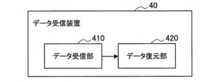
- FIG. 5 is a block diagram showing a configuration example of the data receiving device 40 according to the present embodiment.
- the data receiving device 40 according to the present embodiment includes a data receiving unit 410 and a data restoring unit 420.
- the data receiving unit 410 receives the compressed sensor data from the sensor terminal 30.
- the data decompression unit 420 decompresses the compressed sensor data received by the data reception unit 410.
- the configuration of the sensor data compression system according to this embodiment has been described above in detail.
- the configuration described above with reference to FIGS. 2 to 5 is merely an example, and the configuration of the sensor data compression system according to the present embodiment is not limited to this example.
- the data receiving device 40 according to the present embodiment may further have a learning model reconstruction function and a data analysis function.
- the model building device for rebuilding the learning model may be provided separately from the learning sensor terminal 20 or the data receiving device 40, or may be provided separately with an analysis server having an analysis function. .
- the configuration of the sensor data compression system according to this embodiment can be flexibly modified according to specifications and operation.
- the process mainly performed by the sensor data compression system according to the present embodiment is a learning stage for constructing a mathematical model or a deviation degree detection learning model that sets an optimal compression ratio, and unknown data is detected and the unknown data is used.
- FIG. 6 is a flowchart showing the flow of processing of the learning sensor terminal 20 in the learning stage according to this embodiment.
- the learning sensor terminal 20 constructs a compression ratio learning model by a machine learning method will be described as an example of a mathematical model.
- the sensor 210 of the learning sensor terminal 20 acquires sensor data, and the AD conversion unit 220 performs analog / digital conversion on the sensor data (S1101).
- the data pre-processing unit 230 performs pre-processing such as filtering processing for noise removal and FFT processing for converting time series data into frequency data at predetermined time intervals with respect to the digital signal obtained in step S1101. Processing is performed (S1102).
- the data preprocessing unit 230 may perform a wavelet transform process or the like instead of the FFT process.
- the compression ratio model construction unit 240 constructs a compression ratio learning model using the sensor data preprocessed in step S1102.
- the compression ratio model construction unit 240 may construct the compression ratio learning model using any one of regression learning, unsupervised learning, and reinforcement learning.
- the compression ratio model construction unit 240 When adopting the regression learning (S1103: regression learning), the compression ratio model construction unit 240 according to the present embodiment exploratively obtains the compression ratio with which the evaluation index is optimum for the sensor data, and uses a neural network or the like. The relationship between the sensor data and the optimum compression ratio for the sensor data is learned by the regression analysis method described above.
- the compression ratio model construction unit 240 obtains the compression ratio that optimizes the evaluation index, for example, by random search, grid search, hill climbing method, or the like (S1104).
- the compression ratio model construction unit 240 constructs a compression ratio learning model by regression learning using the sensor data as an explanatory variable and the optimum compression ratio for the sensor data obtained in step S1104 as an objective variable. (S1105).
- the compression ratio model construction unit 240 when adopting unsupervised learning (S1103: unsupervised learning), the compression ratio model construction unit 240 according to the present embodiment performs learning using only sensor data, unlike the above-described regression learning. At this time, the compression ratio model construction unit 240 according to the present embodiment sets the loss function such that the loss becomes smaller as the compression efficiency becomes higher, and the loss becomes the minimum after inputting the sensor data and outputting the compression ratio. As described above, unsupervised learning is performed (S1106). That is, the compression ratio model construction unit 240 according to the present embodiment constructs the compression ratio learning model by obtaining the compression ratio to be optimized by updating the parameters of the neural network by the error back propagation method.
- the compression ratio can be estimated directly from the sensor data without explicitly obtaining the optimum compression ratio unlike the regression learning, and the amount of calculation can be reduced. is there.
- the compression ratio model construction unit 240 when adopting the reinforcement learning (S1103: reinforcement learning), does not strictly obtain the compression ratio with which the evaluation index is optimum, but does not perform strict trial and error and the sensor data. Learn the optimal compression ratio for.
- the compression ratio model construction unit 240 constructs a compression ratio learning model by reinforcement learning with the sensor data as a reward, such as the data compression efficiency defined from the state, the compression ratio, and the restoration error (S1107). ).
- the deviation degree detection model construction unit 250 uses the sensor data (learning data) used to construct the compression ratio learning model by any of the methods described above, and uses the deviation degree detection learning model. Is constructed (S1108). At this time, the deviation degree detection model construction unit 250 according to the present embodiment may construct the One-Class SVM using the learning data or an auto encoder as the deviation degree detection learning model.
- the model transmission unit 260 transmits the constructed compression ratio learning model and deviation degree detection learning model to the sensor terminal (S1109), and ends the processing.
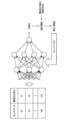
- FIG. 7 is a diagram showing an outline of construction of a compression ratio learning model by regression learning according to this embodiment.
- the regression learning according to the present embodiment first, a plurality of sensor data samples to be compressed are extracted by collecting sensor data and performing AD conversion and preprocessing. Next, the data compression efficiency including the compression ratio and the restoration error as elements is set as the evaluation index.
- the data compression efficiency according to the present embodiment may be set, for example, as shown in the following formula (3) or formula (4).
- Compression efficiency compression ratio x (- ⁇ ) + restoration error x (- ⁇ ) (where ⁇ > 0, ⁇ > 0) ...
- Compression efficiency 1 / (compression ratio ⁇ power) / (restoration error ⁇ power) (where ⁇ > 0, ⁇ > 0) ...
- the above-mentioned decompression error indicates, for example, an error between the data before compression and the data after decompression, and may be, for example, a mean square error.
- ⁇ and ⁇ respectively indicate the weight of the compression ratio and the weight of the restoration error, and the larger the value, the greater the weight, which is regarded as important. That is, the data compression efficiency according to the present embodiment is an index that increases as the compression ratio decreases and the restoration error decreases.
- the compression ratio is changed from a small value, and the compression ratio that maximizes the above data compression efficiency is defined as the optimum compression ratio.
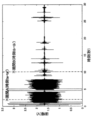
- FIG. 8 is an example of sensor data to be compressed according to this embodiment.
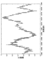
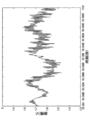
- 9 and 10 are enlarged views of sensor data in period A and period B in FIG. 8, respectively.
- the period A indicates a period from time ta to ta '
- the period B indicates a period from time tb to tb'.
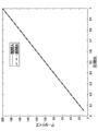
- FIG. 11 is a diagram showing the relationship between the compression ratio and the data size after compression related to the respective sensor data in the period A and the period B.
- FIG. 12 is a diagram showing the relationship between the compression ratio and the restoration error rate for each sensor data in the period A and the period B.
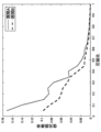
- FIG. 13 is a diagram showing a relationship between the compression ratio and the data compression efficiency for each sensor data in the period A and the period B.
- the respective sensor data in the period A and the period B have the data size after compression increased in proportion to the compression ratio regardless of the content of the data.
- the restoration error rate of each sensor data in the period A and the period B becomes larger.
- the restoration error in the periods A and B is the same. It can be seen that the rates are different.
- the compression efficiency is improved when the compression ratio is increased to a certain value, but the data compression efficiency is increased when the compression ratio exceeds the certain value. Will decrease. Further, it can be seen that the compression ratio that maximizes the data compression efficiency is different between the sensor data in each of the periods A and B, and it is necessary to set the optimum compression ratio according to the sensor data.
- the optimum compression ratio for a certain data is obtained by random search, grid search, hill climbing method, etc., and the sensor data to be compressed is the explanatory variable, and the optimum for the sensor data. Learning is performed with the compression ratio as the objective variable.
- the compression ratio model construction unit 240 may perform regression learning that employs deep learning such as LSTM (Long Short-Term Memory) and CNN (Convolutional Neural Network).
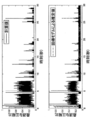
- FIG. 14 is a diagram showing a comparison between the calculated optimum compression ratio for the sensor data shown in FIG. 8 and the optimum compression ratio estimated by the compression ratio learning model constructed by regression learning.
- the optimum compression ratio obtained by grid search for the sensor data to be compressed shown in FIG. 8 is shown in time series.
- the optimum compression ratio estimated by the compression learning model when the sensor data to be compressed shown in FIG. 8 is input is shown in time series.
- FIG. 15 is a diagram showing an outline of compression ratio learning model construction by unsupervised learning according to the present embodiment.
- the construction of the compression ratio learning model by the unsupervised learning according to the present embodiment does not obtain the optimum compression ratio for the sensor data in advance unlike the above-described regression learning, and the loss function is set so that the loss is minimized at the optimum compression ratio. Is a method for directly obtaining the optimum compression ratio from the sensor data.
- the loss function is set so that the higher the data compression efficiency is, the smaller the loss is, for example, by taking the reciprocal of the data compression efficiency shown in the above formulas (3) and (4).
- the compression ratio model construction unit 240 uses the loss function set as described above to learn the parameter update by the error back propagation method so that the loss function is minimized with respect to the output of the neural network. I do. According to such learning, the optimum compression ratio output from the neural network converges with respect to the input sensor data, and a compression ratio learning model can be constructed without obtaining the optimum compression ratio in advance. It is possible.
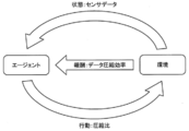
- FIG. 16 is a diagram showing an outline of construction of a compression ratio learning model by reinforcement learning according to this embodiment.
- Reinforcement learning involves learning to control a system that maximizes a numerical value that indicates a long-term goal.
- the compression ratio model construction unit 240 sets the sensor data as the state, the compression ratio as the behavior, and the above-described formulas (3) and (4). Reinforcement learning with compression efficiency as a reward may be performed.
- the compression ratio model construction unit 240 may set the time domain data or the frequency domain data related to the sensor data as a state.
- the compression ratio model construction unit 240 may treat the compression ratio corresponding to the action as a discrete value or a continuous value.
- a deep reinforcement learning method such as Deep-Q-Network (DQN) is considered.
- DQN Deep-Q-Network
- Non-Patent Document 2 a deep reinforcement learning method such as Deep Deterministic Policy Gradient (DDPG) may be adopted.
- DDPG Deep Deterministic Policy Gradient
- the compression ratio model construction unit 240 divides the range that the compression ratio can take into a natural number N, and strengthens the compression ratio of each representative value as a discrete value action. You may study. For example, when the compression ratio is in the range of 0.1 to 0.9 and 5 divisions are performed, the compression ratios of the respective representative values are 0.1, 0.3, 0.5 and 0.7. , 0.9.
- the compression ratio model construction unit 240 performs reinforcement learning by taking an arbitrary value extracted from the range of the compression ratio as an action.
- the reward according to the present embodiment is not limited to the data compression efficiency as shown in FIG. 16 and can be flexibly changed.
- the compression ratio model construction unit 240 according to the present embodiment can also perform the reinforcement learning with the evaluation index including the compression ratio (data transmission amount) or the restoration error as the reward.
- the flow of the learning stage and the learning method according to the present embodiment have been described in detail.
- the flow of the data compression / decompression stage according to this embodiment will be described in detail.
- the sensor data is compressed by the sensor terminal 30 using the compression ratio learning model constructed in the learning stage.
- the compression ratio may not be set correctly for the sensor data. Therefore, in the sensor data compression system according to the present embodiment, in the data compression / decompression stage, when unknown data that is not used as learning data at the time of constructing the compression ratio learning model is detected, the learning sensor terminal 20 or a separate sensor terminal is used.
- the model building apparatus realized by the server or the like re-learns the compression ratio learning model using the unknown data and applies the re-learned compression ratio learning model to the sensor terminal 30.
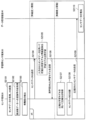
- FIG. 17 is a sequence diagram showing the flow of processing in the data compression / decompression stage according to this embodiment. Note that FIG. 17 shows an example in which the learning sensor terminal 20 according to the present embodiment serves as a model building device and re-learns a learning model.
- the sensor data of the sensor 310 of the sensor terminal 30 is acquired, and the analog / digital conversion is performed by the AD conversion unit 320 (S2101).
- the data preprocessing unit 330 executes preprocessing such as changing to frequency data (S2202).
- the deviation degree detection unit 340 uses the deviation degree detection learning model constructed in step S1108 shown in FIG. 6 to acquire the sensor data and the compression ratio learning currently applied.
- the degree of deviation from the learning data used for building the model is detected (S2103).
- the data communication unit 360 transfers the sensor data that has not been compressed using the compression ratio learning model to the learning sensor terminal 20. It is transmitted (S2104).
- the compression ratio model construction unit 240 and the deviation degree detection model construction unit 250 of the learning sensor terminal 20 use the sensor data received in step S2104 to re-learn the compression ratio model and the deviation degree detection learning model, respectively ( Reconstruction) is performed (S2105).
- the model transmitting unit 260 of the learning sensor terminal transmits the compression ratio model and the deviation degree detection learning model relearned in step S2105 to the sensor terminal 30 (S2106).
- the model transmission unit 260 reconstructs learning from the sensor terminals 30 that have transmitted the sensor data in at least step S2104 among the plurality of sensor terminals 30 connected via the network. You may send the model.
- the model transmission unit 260 includes another sensor terminal 30 installed in association with the same detection target 10 as the sensor terminal 30 that has transmitted the sensor data in step S2104, or another detection target having similar characteristics.
- the reconstructed learning model may be transmitted to the plurality of sensor terminals 30. According to the above-described processing, it is possible to efficiently maintain the accuracy of the compression ratio setting by the plurality of sensor terminals 30.
- the data compression unit 350 uses the compression ratio learning model transmitted from the learning sensor terminal 20 in the learning stage to determine the optimum compression ratio for the sensor data. It is acquired (S2107), and the sensor data is compressed according to the compression ratio (S2108).
- the data communication unit 360 transmits the sensor data compressed in step S2108 to the data receiving device 40 (S2109).
- the data restoration unit 420 of the data reception device 40 executes restoration of the sensor data received by the data reception unit 410 in step S2109 (S2110).
- the data communication unit 360 uses the compressed sensor data as described above. Information regarding different data sizes may be transmitted to the data receiving device 40.
- FIG. 18 is a block diagram showing a hardware configuration example of a model building device according to an embodiment of the present invention.
- the model building device includes, for example, a processor 871, a ROM 872, a RAM 873, a host bus 874, a bridge 875, an external bus 876, an interface 877, an input unit 878, and an output unit 879.
- the storage unit 880, the drive 881, the connection port 882, and the communication unit 883 are included.
- the hardware configuration shown here is an example, and some of the components may be omitted. Moreover, you may further include components other than the components shown here.
- the processor 871 functions as, for example, an arithmetic processing device or a control device, and controls the overall operation of each component or a part thereof based on various programs recorded in the ROM 872, the RAM 873, the storage unit 880, or the removable recording medium 901. To do.
- the ROM 872 is means for storing a program read by the processor 871 and data used for calculation.
- the RAM 873 temporarily or permanently stores, for example, a program read by the processor 871 and various parameters that change appropriately when the program is executed.
- the processor 871, the ROM 872, and the RAM 873 are mutually connected, for example, via the host bus 874 capable of high-speed data transmission.
- the host bus 874 is connected to, for example, an external bus 876 having a relatively low data transmission rate via a bridge 875.
- the external bus 876 is connected to various components via the interface 877.
- Input unit 8708 As the input unit 878, for example, a mouse, a keyboard, a touch panel, a button, a switch, a microphone, a lever or the like is used. Further, as the input unit 878, a remote controller (hereinafter, remote controller) capable of transmitting a control signal using infrared rays or other radio waves may be used.
- a remote controller capable of transmitting a control signal using infrared rays or other radio waves may be used.
- the output unit 879 includes, for example, a display device (display device) such as a CRT (Cathode Ray Tube), an LCD, or an organic EL, an audio output device such as a speaker or headphones, a printer, a mobile phone, a facsimile, or the like, and the acquired information. Is a device capable of visually or audibly notifying a user.
- a display device such as a CRT (Cathode Ray Tube), an LCD, or an organic EL
- an audio output device such as a speaker or headphones
- printer a printer
- a mobile phone a facsimile, or the like
- the storage unit 880 is a device for storing various data.
- a magnetic storage device such as a hard disk drive (HDD), a semiconductor storage device, an optical storage device, a magneto-optical storage device, or the like is used.
- the drive 881 is a device that reads information recorded on a removable recording medium 901 such as a magnetic disk, an optical disk, a magneto-optical disk, or a semiconductor memory, or writes information on the removable recording medium 901.
- a removable recording medium 901 such as a magnetic disk, an optical disk, a magneto-optical disk, or a semiconductor memory
- the removable recording medium 901 is, for example, a DVD medium, a Blu-ray (registered trademark) medium, an HD DVD medium, various semiconductor storage media, or the like.
- the removable recording medium 901 may be, for example, an IC card equipped with a non-contact type IC chip, an electronic device, or the like.
- connection port 882 is, for example, a USB (Universal Serial Bus) port, an IEEE 1394 port, a SCSI (Small Computer System Interface), an RS-232C port, or a port for connecting an external connection device 902 such as an optical audio terminal. is there.
- the external connection device 902 is, for example, a printer, a portable music player, a digital camera, a digital video camera, an IC recorder, or the like.
- the communication unit 883 is a communication device for connecting to the network 903, and includes, for example, a wired or wireless LAN, a Bluetooth (registered trademark) or a communication card for WUSB (Wireless USB), a router for optical communication, and an ADSL (Asymmetric). It is a router for Digital Subscriber Line) or a modem for various communications. Further, it may be connected to various telephone networks such as public telephone networks, mobile telephone carrier networks, and extension telephone networks.
- the sensor data compression system includes the sensor terminal 30 and the model building device realized by the learning sensor terminal 20 and a separate server. According to the sensor data compression system of one embodiment of the present invention, it is possible to maintain both data analysis accuracy and communication cost reduction.
- the effects described in the present specification are merely explanatory or exemplifying ones, and are not limiting. That is, the technique according to the present disclosure may have other effects that are apparent to those skilled in the art from the description of the present specification, in addition to or instead of the above effects.
- a program for causing hardware such as a CPU, a ROM, and a RAM incorporated in a computer to exhibit the same functions as the configurations of the learning sensor terminal 20 (model building device) and the sensor terminal 30.
- a non-transitory computer-readable recording medium in which the program is recorded may be provided.
- the steps related to the processing of the sensor data compression system in this specification do not necessarily have to be processed in time series in the order described in the flowcharts and sequence diagrams.
- the steps related to the processing of the sensor data compression system may be processed in an order different from the order described in the flowcharts and sequence diagrams, or may be processed in parallel.
Landscapes
- Engineering & Computer Science (AREA)
- Theoretical Computer Science (AREA)
- Compression, Expansion, Code Conversion, And Decoders (AREA)
Abstract
センサデータを取得するセンサ、取得された前記センサデータの特徴量に基づいて圧縮センシングに係る圧縮比を取得する数理モデルを用いて、前記センサデータを前記圧縮比で圧縮するデータ圧縮部、前記データ圧縮部により圧縮された前記センサデータを送信するデータ通信部、および取得された前記センサデータと前記数理モデルの構築に用いられたセンサデータとの乖離度を検出する乖離度検出部、を備え、前記データ通信部は、検出された前記乖離度が閾値を超える場合、前記圧縮比による圧縮が行われていない前記センサデータをモデル構築装置に送信する、センサ端末と、前記センサ端末から受信した前記圧縮比による圧縮が行われていない前記センサデータを用いて前記数理モデルを再構築する圧縮比モデル構築部、および前記圧縮比モデル構築部により再構築された前記数理モデルを前記センサ端末に送信するモデル送信部、を備える、前記モデル構築装置と、から成るセンサデータ圧縮システムが提供される。
Description
本発明は、センサデータ圧縮システム、センサ端末、モデル構築装置、およびプログラムに関する。
近年、検知対象に設置したセンサ端末によりセンサデータを取得し、サーバにより当該センサデータを分析することで、検知対象に係る各種の状態を判定する技術が普及している。また、センサ端末からサーバにセンサデータを送信する際に、データ圧縮を行うことで、通信コストを削減する手法が提案されている。
例えば、特開2016-63297号公報(特許文献1)には、センサ端末からサーバへ送信するセンサデータの圧縮符号化を動的に適正化するために、センサ端末とは別途に設けた情報処理装置により圧縮データから復元されたデータの統計情報に基づいて圧縮符号化情報を生成し、当該圧縮符号化情報をセンサ端末で利用する技術が開示されている。
しかし、特許文献1では、圧縮比の最適化については述べられておらず、また、数理モデルを用いた圧縮比の最適化や、最適な圧縮比を計算能力が低いセンサ端末側で動的に設定する手法についても議論されていない。
そこで、本発明は、上記に鑑みてなされたものであり、本発明の目的とするところは、データ分析精度の維持と通信コストの削減とを両立することが可能な、新規かつ改良されたセンサデータ圧縮システム、センサ端末、モデル構築装置、およびプログラムを提供することにある。ここでデータ分析精度とは、目的に応じた分析に必要な情報量を落とさず、誤差の少ないデータ分析結果が得られる度合いである。
上記課題を解決するために、本発明のある観点によれば、センサデータを取得するセンサ、取得された前記センサデータの特徴量に基づいて圧縮センシングに係る圧縮比を取得する数理モデルを用いて、前記センサデータを前記圧縮比で圧縮するデータ圧縮部、前記データ圧縮部により圧縮された前記センサデータを送信するデータ通信部、および取得された前記センサデータと前記数理モデルの構築に用いられたセンサデータとの乖離度を検出する乖離度検出部、を備え、前記データ通信部は、検出された前記乖離度が閾値を超える場合、前記圧縮比による圧縮が行われていない前記センサデータをモデル構築装置に送信する、センサ端末と、前記センサ端末から受信した前記圧縮比による圧縮が行われていない前記センサデータを用いて前記数理モデルを再構築する圧縮比モデル構築部、および前記圧縮比モデル構築部により再構築された前記数理モデルを前記センサ端末に送信するモデル送信部、を備える、前記モデル構築装置と、から成るセンサデータ圧縮システムが提供される。
また、前記数理モデルは、前記センサデータに対する前記圧縮比を、復元誤差と前記圧縮比とを含む評価指標により動的に変更するよう、機械学習手法を用いて構築された圧縮比学習モデルであり、前記圧縮比モデル構築部は、前記センサ端末から受信した前記圧縮比による圧縮が行われていない前記センサデータを用いて前記圧縮比学習モデルの再構築を行い、前記モデル送信部は、前記圧縮比モデル構築部による再構築が行われた前記圧縮比学習モデルを前記センサ端末に送信してもよい。
また、前記乖離度検出部は、前記圧縮比学習モデルの構築に用いられた前記センサデータを用いて構築された乖離度検出学習モデルを用いて前記乖離度を検出してもよい。
また、前記モデル構築装置は、前記センサ端末から受信した前記圧縮比による圧縮が行われていない前記センサデータを用いて前記乖離度検出学習モデルを構築する乖離度検出モデル構築部、をさらに備え、前記モデル送信部は、前記乖離度検出モデル構築部により構築された前記乖離度検出学習モデルを前記センサ端末に送信してもよい。
また、前記圧縮比モデル構築部は、教師あり学習の一つである回帰学習、教師なし学習、または強化学習のいずれかの手法を用いて前記圧縮比学習モデルを構築してもよい。
また、前記圧縮比モデル構築部は、前記評価指標を最適化する前記圧縮比を求め、前記センサデータを説明変数、当該センサデータに対する最適な圧縮比を目的変数とした回帰学習により前記圧縮比学習モデルを構築してもよい。
また、前記圧縮比モデル構築部は、前記評価指標を最適化する前記圧縮比を、ランダムサーチ、グリッドサーチ、または山登り法のいずれかにより求めてもよい。
また、前記圧縮比モデル構築部は、データ圧縮効率が高いほど損失が小さくなる損失関数を用いて、最適化する前記圧縮比を、誤差逆伝播法によるニューラルネットワークのパラメータ更新で求める教師なし学習により前記圧縮比学習モデルを構築してもよい。
また、前記圧縮比モデル構築部は、前記センサデータを状態、前記圧縮比を行動、データ圧縮効率を報酬として、強化学習により前記圧縮比学習モデルを構築してもよい。
また、前記圧縮比モデル構築部は、前記センサデータに係る時間領域のデータまたは周波数領域のデータを状態として強化学習を行ってもよい。
また、前記圧縮比モデル構築部は、前記圧縮比の範囲を自然数Nで分割し、それぞれの代表値の圧縮比を離散値の行動として強化学習を行ってもよい。
また、前記圧縮比モデル構築部は、前記圧縮比を連続値の行動として強化学習を行ってもよい。
また、前記圧縮比モデル構築部は、前記圧縮比または復元誤差を含む評価指標を報酬とした強化学習を行ってもよい。
また、上記課題を解決するために、本発明の別の観点によれば、センサデータを取得するセンサと、取得された前記センサデータの特徴量に基づいて圧縮センシングに係る圧縮比を取得する数理モデルを用いて、前記センサデータを前記圧縮比で圧縮するデータ圧縮部と、前記データ圧縮部により圧縮された前記センサデータを送信するデータ通信部と、取得された前記センサデータと前記数理モデルの構築に用いられたセンサデータとの乖離度を検出する乖離度検出部と、を備え、前記データ通信部は、検出された前記乖離度が閾値を超える場合、前記圧縮比による圧縮が行われていない前記センサデータをモデル構築装置に送信し、当該センサデータを用いて再構築された前記数理モデルを受信する、センサ端末が提供される。
また、上記課題を解決するために、本発明の別の観点によれば、取得したセンサデータの特徴量に基づいて圧縮センシングに係る圧縮比を取得する数理モデルを用いて前記センサデータを前記圧縮比で圧縮するセンサ端末から、前記圧縮比による圧縮が行われていない前記センサデータを受信した場合、当該センサデータを用いて前記数理モデルを再構築する圧縮比モデル構築部と、前記圧縮比モデル構築部により再構築された前記数理モデルを、ネットワークを介して接続される複数のセンサ端末のうち、少なくとも前記圧縮比による圧縮が行われていない前記センサデータの送信を行ったセンサ端末に送信するモデル送信部と、を備える、モデル構築装置が提供される。
また、上記課題を解決するために、本発明の別の観点によれば、コンピュータを、センサデータを取得するセンサと、取得された前記センサデータの特徴量に基づいて圧縮センシングに係る圧縮比を取得する数理モデルを用いて、前記センサデータを前記圧縮比で圧縮するデータ圧縮部と、前記データ圧縮部により圧縮された前記センサデータを送信するデータ通信部と、取得された前記センサデータと前記数理モデルの構築に用いられたセンサデータとの乖離度を検出する乖離度検出部と、を備え、前記データ通信部は、検出された前記乖離度が閾値を超える場合、前記圧縮比による圧縮が行われていない前記センサデータをモデル構築装置に送信し、当該センサデータを用いて再構築された前記数理モデルを受信する、センサ端末、として機能させるためのプログラムが提供される。
また、上記課題を解決するために、本発明の別の観点によれば、コンピュータを、取得したセンサデータの特徴量に基づいて圧縮センシングに係る圧縮比を取得する数理モデルを用いて前記センサデータを前記圧縮比で圧縮するセンサ端末から、前記圧縮比による圧縮が行われていない前記センサデータを受信した場合、当該センサデータを用いて前記数理モデルを再構築する圧縮比モデル構築部と、前記圧縮比モデル構築部により再構築された前記数理モデルを、ネットワークを介して接続される複数のセンサ端末のうち、少なくとも前記圧縮比による圧縮が行われていない前記センサデータの送信を行ったセンサ端末に送信するモデル送信部と、を備える、モデル構築装置、として機能させるためのプログラムが提供される。
以上説明したように本発明によれば、データ分析精度の維持と通信コストの削減とを両立することが可能となる。
以下に添付図面を参照しながら、本発明の好適な実施の形態について詳細に説明する。なお、本明細書および図面において、実質的に同一の機能構成を有する構成要素については、同一の符号を付することにより重複説明を省略する。
<1.一実施形態>
<<1.1.概要>>
まず、本発明の概要について述べる。本発明はセンサデータ(以下、単に、データ、と称する場合がある)の情報量を表す指標であるスパース性(0成分が多いという性質)の度合いが変動する振動データ、映像データ、音声データ等の広帯域のデータを、エッジ側のセンサ端末で効率的に圧縮し、無線などの低帯域リンクでデータ伝送するための技術である。
<<1.1.概要>>
まず、本発明の概要について述べる。本発明はセンサデータ(以下、単に、データ、と称する場合がある)の情報量を表す指標であるスパース性(0成分が多いという性質)の度合いが変動する振動データ、映像データ、音声データ等の広帯域のデータを、エッジ側のセンサ端末で効率的に圧縮し、無線などの低帯域リンクでデータ伝送するための技術である。
ここで、上記のスパース性の度合いとは元のデータサイズに対して、元のデータを再現するのに最低限必要なデータサイズを指す。一般に同じデータサイズを有するデータであっても、データの有する情報量が多いほどスパース度は高く、データの有する情報量が少ないほどスパース度は低いといえる。
また、センサデータを収集しデータマイニングを行う場合、高精度なデータマイニングを実現するためには、一般に収集するセンサデータのデータ量を増やす必要がある。しかしながら、センサデータを送信するエッジ端末、すなわちセンサ端末は、メモリ容量やストレージ容量、計算能力などに大きな制約を有するのが一般的である。特にセンサ端末で取得したセンサデータを無線リンクで分析サーバに送る場合には、ネットワーク帯域に大きな制約が発生する。このようにデータの情報量とリソースの浪費とにはトレードオフの関係があることから、センサ端末側で効率的にデータを圧縮して、データ情報量を維持しつつ、データの送信量を削減することが求められる。
ここで、データ圧縮を効果的に行う手法としては、例えば、特許文献1に開示される技術が挙げられる。しかし、上述したように、特許文献1に開示される技術では、圧縮符号化情報を生成するために、センサ端末とは別途に情報処理装置を設ける必要があり、システム構築のコストが増大することが想定される。
また、特許文献1では、圧縮比の最適化、特に数理モデルを用いた圧縮比の最適化については議論されておらず、未知のセンサデータが取得された場合には、効率の良いデータ圧縮を行うことが困難である。
一方、本発明の一実施形態に係るセンサデータ圧縮システムでは、サンプリング周波数が比較的高いデータや、データ転送量が大きいデータを送信する場合において、計算能力やバッテリ容量などのリソースの制約が大きいエッジ側のセンサ端末で最適な圧縮比を動的に取得し、当該圧縮比を用いてセンサデータの圧縮を行うことを特徴の一つとする。
この際、本発明の一実施形態に係るセンサ端末は、センサデータの情報量に応じて最適な圧縮比を動的に変更する制御を、予め構築された数理モデルを利用することで実現する。上記の制御によれば、計算能力の低いエッジ側のセンサ端末でも、軽量な処理で最適な圧縮比を設定することが可能となる。
なお、ここで、ここで上記の圧縮比とは元のデータのサイズに対する圧縮後のデータのサイズの比であり、圧縮比が小さいほど圧縮後のデータサイズが小さいことを示す。また最適な圧縮比とは、データの情報量の損失を最小限にしつつ、送信するデータのサイズも最小限にできる圧縮比と定義してよい。
さらには、本実施形態に係るセンサデータ圧縮システムでは、未知のセンサデータをエッジ側のセンサ端末が取得した場合であっても、当該センサ端末で、数理モデルの構築時に用いられていないセンシングータと取得したセンサデータの乖離度を検出し、乖離度が閾値を超える場合には、当該乖離度が高いセンサデータを用いて数理モデルの再構築を行うことで、圧縮比設定の精度を維持することを特徴の一つとする。
上記の特徴を実現するために、本実施形態では、まずデータの情報量に応じて最適な圧縮比に逐次動的に設定するための数理モデルを予め計算能力の高い端末で構築する。なお、上記の数理モデルは、例えば、センサデータに対する圧縮比を、復元誤差率と圧縮比とを含む評価指標により動的に変更するよう、機械学習手法を用いて構築された圧縮比学習モデルであってもよい。
本実施形態では、例えば、上記のように構築された圧縮比学習モデルをエッジ側のセンサ端末に移植して動作させることにより、圧縮比の最適化を逐次センサ端末側で行う場合と比較して、センサ端末での計算コストや、ゲートウェイと制御データのオーバーヘッドを抑制することが可能である。
また、エッジ端のセンサ端末において、上記の圧縮比学習モデルを利用して、データに応じた最適な圧縮比を動的に変更することにより、データ分析精度の維持と通信コストの抑制を両立することができ、この結果、圧縮効率の高いデータ圧縮が可能となる。
さらには、モデル構築に機械学習を用いた場合、一般に未知のデータに対しての推定精度は劣化するが、本実施形態では学習済みのデータと圧縮対象のデータとの乖離度を検出し、乖離度が高い場合は未知のデータとみなして、計算能力の高い端末で再学習を行いセンサ端末の学習モデルを更新することにより、最適な圧縮比の推定の精度の劣化を防止することができる。
なお、本実施形態に係るセンサ端末によるセンサデータの圧縮には、D.L. Donoho,“Compressed sensing", IEEE Transactions onInformation Theory, vol.52, no.4, pp.1289--1306, Apr. 2006.(非特許文献1)に記載されるような圧縮センシング技術が用いられてよい。圧縮センシングとは、スパース性を有する高次元の信号を少ない観察から復元する手法である。圧縮センシングでは、一般に、送信側における圧縮処理の計算コストは低いが、受信側における復元処理の計算コストが高いことから、計算能力の低いエッジ側のセンサ端末によるデータ圧縮に適した技術といえる。
ここで、圧縮センシングの概要について説明する。図19は、圧縮センシングを用いたデータ圧縮の概要について説明するための図である。例えば、図19に示すように、元のデータをX、データを圧縮する観測行列をΦ、圧縮後の観測データをYと定義した場合、圧縮後の観測データは、下記の数式(1)により表される。

ここで、元のデータXのサイズをN、圧縮後の観察データYのサイズをMとすると、観測行列ΦのサイズはM×Nとなる。本実施形態に係る圧縮センシングでは、上記M、すなわち観測行列Φの行数を変更することにより、圧縮後の観察データYに係る圧縮比M/Nを調整することが可能である。なお、非特許文献1では、圧縮比の動的な変更については議論されておらず、Mの変更による圧縮比の調整についても示唆されていない。このため、本実施形態に係る圧縮センシングは、動的な圧縮比の設定を容易に可能とする点において、非特許文献1に記載される技術と比較して優れた効果を奏するものである。
続いて、圧縮センシング技術における復元について述べる。上記数式(1)においては、未知数>式の数、となることから、通常は一意な解を求めることができないが、X=Ψx、のように、元のデータXが要素に0を多く含むスパース行列xと変換行列Ψの積により表すことができるとすると、圧縮後の観察データYを完全に復元できる可能性がある。具体的には、下記の数式(2)を満たす条件の下で、xのL1ノルムを最小化する問題に帰着して求めることが可能である。

この際、求めたxを利用して、X=Ψx、を計算することにより、元のデータXを復元することが可能である。ただし、圧縮する対象データに対して十分な圧縮比が設定されない場合、復元後のデータと元のデータに誤差が生じることも想定される。このため、本実施形態では、復元誤差と圧縮比とを含む評価指標を学習に利用することで、上記の懸念を解決する。
以上、本発明の一実施形態に係る概要について述べた。以下、上記を実現する構成や当該構成により奏される効果について、より詳細に説明する。
<<1.2.構成>>
上述したように、本実施形態に係るセンサデータ圧縮システムは、多数のセンサ端末が設置された環境において、センサ端末側で低計算コストで設定した最適な圧縮比によりセンサデータを圧縮し、受信端末でデータを復元することを可能とする。ここで、上記の圧縮比とは、(圧縮前のデータサイズ)÷(圧縮後のデータサイズ)、により算出される指標であり、圧縮比が高い程、圧縮後のデータサイズが小さくなる。
上述したように、本実施形態に係るセンサデータ圧縮システムは、多数のセンサ端末が設置された環境において、センサ端末側で低計算コストで設定した最適な圧縮比によりセンサデータを圧縮し、受信端末でデータを復元することを可能とする。ここで、上記の圧縮比とは、(圧縮前のデータサイズ)÷(圧縮後のデータサイズ)、により算出される指標であり、圧縮比が高い程、圧縮後のデータサイズが小さくなる。
なお、得られたデータに対して様々な圧縮比を設定し、それぞれにおける復元誤差や圧縮比の関係から最適な圧縮比を求めることも理論上可能であるが、一般にデータの復元処理は計算コストが高く、リソースの制約の大きいセンサ端末では膨大な処理遅延が生じる可能性あり、不向きである。また、最適化の処理をネットワークを介したサーバ側で行うことは、圧縮されない生のデータをネットワークを介してサーバに伝送する必要があり、ネットワーク帯域の浪費と処理遅延を生じさせる。
このため、本実施形態に係るセンサデータ圧縮システムでは、最適化制御を逐次エッジ側のセンサ端末で行うのではなく、予め構築された、最適な圧縮比を求める数理モデルを利用することで対応する。
本実施形態では、センサデータの情報量による復元誤差に応じてセンサ端末において圧縮比を動的に変更してよい。例えば、データの情報量が低い場合には圧縮比を小さくし、逆に情報量が多い場合には圧縮比を高くする。ここで情報量の指標として、例えばデータのスパース性が挙げられる。同じデータサイズでも0の値が多い程スパース性は高く、逆に0以外の値が多い程スパース性は低い。このため、圧縮比を情報量と復元側での復元を考慮して動的に変えることにより、データの高圧縮比と高復元精度を両立することが可能となる。
しかしながら、センサデータの圧縮を行うセンサ端末においては、最適な圧縮比を得るために解析的にスパース性を求めることや、復元誤差を求めることは計算量が膨大となるため、困難である。そこで、本実施形態では、最適な圧縮比の設定を、例えば、機械学習手法を用いて構築された数理モデルで行うことにより、解析的に最適解を求める場合と比較して高速な計算を実現し、計算能力の低いエッジ端のセンサ端末においても圧縮比の最適化を行うことを可能とする。
また、本実施形態に係るセンサデータ圧縮システムでは、数理モデルの構築に用いられていない未知のデータがエッジ側のセンサ端末で取得された場合、当該未知データを計算能力の高い装置に伝送し、数理モデルを再構築することで最適な圧縮比の推定の精度を維持することを可能とする。
一般に機械学習では、学習していない未知のデータに対しての精度が悪くなるが、本実施形態ではセンサ端末で、圧縮対象のデータに対して学習済みのデータに対する乖離度を検出し、当該乖離度が高いデータを未知のデータとみなして、計算能力が高い装置で未知データの再学習を行う。また、更新された学習モデルをセンサ端末に移行し、センサ端末で最適な圧縮比の推定を行うことで精度の劣化を防止することができる。
図1は、本実施形態に係るセンサデータ圧縮システムが適用され得る想定環境を示す図である。ここでは、複数のセンサ端末70a~70eが取得したセンサデータを無線リンクでゲートウェイ80に送信し、ゲートウェイ80を経由してデータ分析サーバ90でデータを復元してデータ分析を行う場合を想定する。また、データ圧縮の手法としては、例えば、上述した圧縮センシングを想定する。一般に、データマイニングなどを行うデータ分析サーバ90では、データ分析精度を上げるために複数のセンサ端末70a~70eから大容量のデータ量を収集する必要がある。しかし、通常の場合、センサ端末70a~70eにおいてバッテリを浪費し、ネットワーク側でも無線帯域の浪費やデータを蓄積するストレージを浪費してしまう可能性がある。
また、一般にデータを送信元からネットワーク経由で宛先に伝送する場合、送信元に近い端末でデータ圧縮行う方が、ネットワークに流れる総データ量は少なくなるため、望ましい。特に、センサ端末70a~70eは低帯域の無線リンクで接続されていることもあるため、送信元のセンサ端末70a~70eにおいてデータ圧縮を行うことが通信コストの削減に対し最も効果がある。しかしながらセンサ端末70a~70eで圧縮比の動的制御を行う場合、最適な圧縮比をリアルタイムに計算することは、解析的にスパース性を求めたり復元誤差を求めたりすることの計算量が膨大となるため、リソースの制約上、困難である場合もある。
そこで、本実施形態では、機械学習手法などを用いて構築した数理モデルを利用した最適な圧縮比設定をセンサ端末側で行う。一般に機械学習は、学習モデルを作成する際に、大きな計算リソースを要するが、構築された学習モデルを用いて推論を行う際は軽い処理で行うことができる。このため、最適な圧縮比を学習する端末は推論時に設置されるセンサ端末とは別途の端末であってもよい。
図2は、本実施形態に係るセンサデータ圧縮システムの構成例を示すブロック図である。本実施形態に係るセンサデータ圧縮システムは、例えば、図2に示すように、学習用センサ端末20、複数のセンサ端末30a、およびデータ受信装置40を備える。ここで、学習用センサ端末20およびセンサ端末30は、検知対象10に附随して設置される。
(検知対象10)
本実施形態に係る検知対象10は、振動、画像、音など、各種のセンサデータを取得する対象である。本実施形態に係る検知対象10は、例えば、工場に設置された各種の設備、オフィスに設置された各種の機器、また各種の建設物・建築物などであり得る。
本実施形態に係る検知対象10は、振動、画像、音など、各種のセンサデータを取得する対象である。本実施形態に係る検知対象10は、例えば、工場に設置された各種の設備、オフィスに設置された各種の機器、また各種の建設物・建築物などであり得る。
(学習用センサ端末20)
本実施形態に係る学習用センサ端末20は、最適な圧縮比を求める圧縮比学習モデル(数理モデルの一例)や、取得したセンサデータと学習データとの乖離度を求める乖離度検出学習モデルを構築する端末である。学習用センサ端末20は、本発明に係るモデル構築装置の一例である。
本実施形態に係る学習用センサ端末20は、最適な圧縮比を求める圧縮比学習モデル(数理モデルの一例)や、取得したセンサデータと学習データとの乖離度を求める乖離度検出学習モデルを構築する端末である。学習用センサ端末20は、本発明に係るモデル構築装置の一例である。
(センサ端末30)
本実施形態に係るセンサ端末30は、学習用センサ端末20が構築した圧縮比学習モデルを用いて、取得したセンサデータに対する圧縮比を設定し、当該圧縮比を用いて圧縮したセンサデータをデータ受信装置40に送信する端末である。本実施形態に係るセンサ端末30は、図2に示すように、単一の検知対象10に対し、複数設置されてもよい。
本実施形態に係るセンサ端末30は、学習用センサ端末20が構築した圧縮比学習モデルを用いて、取得したセンサデータに対する圧縮比を設定し、当該圧縮比を用いて圧縮したセンサデータをデータ受信装置40に送信する端末である。本実施形態に係るセンサ端末30は、図2に示すように、単一の検知対象10に対し、複数設置されてもよい。
(データ受信装置40)
本実施形態に係るデータ受信装置40は、センサ端末30が圧縮したセンサデータを受信し、必要に応じて復元する装置である。なお、本実施形態に係るデータ受信装置40は、後述する学習モデルの再構築機能や、データ分析機能をさらに有してもよい。
本実施形態に係るデータ受信装置40は、センサ端末30が圧縮したセンサデータを受信し、必要に応じて復元する装置である。なお、本実施形態に係るデータ受信装置40は、後述する学習モデルの再構築機能や、データ分析機能をさらに有してもよい。
続いて、本実施形態に学習用センサ端末20の構成についてより詳細に説明する。図3は、本実施形態に係る学習用センサ端末20の構成例を示すブロック図である。図3を参照すると、本実施形態に係る学習用センサ端末20は、センサ210、AD変換部220、データ前処理部230、圧縮比モデル構築部240、乖離度検出モデル構築部250、およびモデル送信部260を備える。
((センサ210))
本実施形態に係るセンサ210は、例えば、振動センサ、歪センサ、音響センサ、画像センサなどの各種のセンサであり得る。
本実施形態に係るセンサ210は、例えば、振動センサ、歪センサ、音響センサ、画像センサなどの各種のセンサであり得る。
((AD変換部220))
本実施形態に係るAD変換部220は、センサ210が取得したセンサデータがアナログ信号である場合に、アナログ・デジタル変換を行う。
本実施形態に係るAD変換部220は、センサ210が取得したセンサデータがアナログ信号である場合に、アナログ・デジタル変換を行う。
((データ前処理部230))
本実施形態に係るデータ前処理部230は、デジタル信号に変換されたセンサデータに対し、雑音除去のフィルタリング、計測値変換、またFFT(Fast Fourier Transform:高速フーリエ変換)等の周波数変換処理を行う。
本実施形態に係るデータ前処理部230は、デジタル信号に変換されたセンサデータに対し、雑音除去のフィルタリング、計測値変換、またFFT(Fast Fourier Transform:高速フーリエ変換)等の周波数変換処理を行う。
((圧縮比モデル構築部240))
本実施形態に係る圧縮比モデル構築部240は、入力されるセンサデータの特徴量に基づいて圧縮センシングに係る圧縮比を取得する数理モデルを構築する。上記の数理モデルは、例えば、機械学習手法により構築された学習モデルであってもよい。本実施形態に係る圧縮比モデル構築部240は、例えば、センサデータに対する圧縮比を復元誤差と圧縮比とを含む評価指標により動的に変更する圧縮比学習モデルを、教師あり学習の一つである回帰学習、教師なし学習、または強化学習などにより構築することが可能である。一方、本実施形態に係る数理モデルは、上記の例に限定されず、例えば、センサデータの特徴量と最適な圧縮比との対応を示すグラフやデータであってもよい。本実施形態に係る圧縮比モデル構築部240が有する機能の詳細については別途後述する。
本実施形態に係る圧縮比モデル構築部240は、入力されるセンサデータの特徴量に基づいて圧縮センシングに係る圧縮比を取得する数理モデルを構築する。上記の数理モデルは、例えば、機械学習手法により構築された学習モデルであってもよい。本実施形態に係る圧縮比モデル構築部240は、例えば、センサデータに対する圧縮比を復元誤差と圧縮比とを含む評価指標により動的に変更する圧縮比学習モデルを、教師あり学習の一つである回帰学習、教師なし学習、または強化学習などにより構築することが可能である。一方、本実施形態に係る数理モデルは、上記の例に限定されず、例えば、センサデータの特徴量と最適な圧縮比との対応を示すグラフやデータであってもよい。本実施形態に係る圧縮比モデル構築部240が有する機能の詳細については別途後述する。
((乖離度検出モデル構築部250))
本実施形態に係る乖離度検出モデル構築部250は、入力されるセンサデータと、圧縮比学習モデル(数理モデル)の構築に用いられたセンサデータ(学習データ)との乖離度を検出する乖離度検出学習モデルを構築する。この際、本実施形態に係る乖離度検出モデル構築部250は、上記学習データを用いたOne-Class SVMや、オートエンコーダなどを乖離度検出学習モデルとして構築してもよい。
本実施形態に係る乖離度検出モデル構築部250は、入力されるセンサデータと、圧縮比学習モデル(数理モデル)の構築に用いられたセンサデータ(学習データ)との乖離度を検出する乖離度検出学習モデルを構築する。この際、本実施形態に係る乖離度検出モデル構築部250は、上記学習データを用いたOne-Class SVMや、オートエンコーダなどを乖離度検出学習モデルとして構築してもよい。
((モデル送信部260))
本実施形態に係るモデル送信部260は、圧縮比モデル構築部240が構築した圧縮比学習モデルや、乖離度検出モデル構築部250が構築した乖離度検出学習モデルを、単一または複数のセンサ端末30に送信する。
本実施形態に係るモデル送信部260は、圧縮比モデル構築部240が構築した圧縮比学習モデルや、乖離度検出モデル構築部250が構築した乖離度検出学習モデルを、単一または複数のセンサ端末30に送信する。
次に、本実施形態にセンサ端末30の構成についてより詳細に説明する。図4は、本実施形態に係るセンサ端末30の構成例を示すブロック図である。図4を参照すると、本実施形態に係るセンサ端末30は、センサ310、AD変換部320、データ前処理部330、乖離度検出部340、データ圧縮部350、およびデータ通信部360を備える。なお、センサ310、AD変換部320、データ前処理部330については、上述した学習用センサ端末20のセンサ210、AD変換部220、データ前処理部230と同等の機能を有してよいため、詳細な説明は省略する。
((乖離度検出部340))
本実施形態に係る乖離度検出部340は、学習用センサ端末20の乖離度検出モデル構築部250が構築した乖離度検出学習モデルを用いて、入力されたセンサデータと、圧縮比学習モデルの構築に用いられた学習データとの乖離度を検出する。本実施形態に係る乖離度検出部340が有する機能の詳細については別途詳細に説明する。
本実施形態に係る乖離度検出部340は、学習用センサ端末20の乖離度検出モデル構築部250が構築した乖離度検出学習モデルを用いて、入力されたセンサデータと、圧縮比学習モデルの構築に用いられた学習データとの乖離度を検出する。本実施形態に係る乖離度検出部340が有する機能の詳細については別途詳細に説明する。
((データ圧縮部350))
本実施形態に係るデータ圧縮部350は、学習用センサ端末20の圧縮比モデル構築部240が構築した数理モデルを用いて、入力されたセンサデータに対する最適な圧縮比を取得し、当該圧縮比によるデータ圧縮を行う。
本実施形態に係るデータ圧縮部350は、学習用センサ端末20の圧縮比モデル構築部240が構築した数理モデルを用いて、入力されたセンサデータに対する最適な圧縮比を取得し、当該圧縮比によるデータ圧縮を行う。
((データ通信部360))
本実施形態に係るデータ通信部360は、ネットワークを介して、学習用センサ端末20やデータ受信装置40とのデータ通信を行う。本実施形態に係るデータ通信部360は、例えば、データ圧縮部350が圧縮したセンサデータをデータ受信装置40に送信する。また、本実施形態に係るデータ通信部360は、例えば、乖離度検出部340が学習データとの乖離度が閾値を超えると判定したセンサデータを、データ圧縮部350による圧縮が行われていない状態で学習用センサ端末20などのモデル構築装置に送信する。本実施形態に係るデータ通信部360が有する機能の詳細については別途後述する。
本実施形態に係るデータ通信部360は、ネットワークを介して、学習用センサ端末20やデータ受信装置40とのデータ通信を行う。本実施形態に係るデータ通信部360は、例えば、データ圧縮部350が圧縮したセンサデータをデータ受信装置40に送信する。また、本実施形態に係るデータ通信部360は、例えば、乖離度検出部340が学習データとの乖離度が閾値を超えると判定したセンサデータを、データ圧縮部350による圧縮が行われていない状態で学習用センサ端末20などのモデル構築装置に送信する。本実施形態に係るデータ通信部360が有する機能の詳細については別途後述する。
次に、本実施形態にデータ受信装置40の構成についてより詳細に説明する。図5は、本実施形態に係るデータ受信装置40の構成例を示すブロック図である。図5を参照すると、本実施形態に係るデータ受信装置40は、データ受信部410およびデータ復元部420を備える。
((データ受信部410))
本実施形態に係るデータ受信部410は、センサ端末30から圧縮後のセンサデータを受信する。
本実施形態に係るデータ受信部410は、センサ端末30から圧縮後のセンサデータを受信する。
((データ復元部420))
本実施形態に係るデータ復元部420は、データ受信部410が受信した圧縮後のセンサデータの復元を行う。
本実施形態に係るデータ復元部420は、データ受信部410が受信した圧縮後のセンサデータの復元を行う。
以上、本実施形態に係るセンサデータ圧縮システムの構成について詳細に説明した。なお、図2~図5を用いて説明した上記の構成はあくまで一例であり、本実施形態に係るセンサデータ圧縮システムの構成は係る例に限定されない。例えば、上述したように、本実施形態に係るデータ受信装置40は、学習モデルの再構築機能や、データ分析機能をさらに有してもよい。一方で、学習モデルの再構築を行うモデル構築装置は、学習用センサ端末20やデータ受信装置40とは別途に備えられてもよいし、分析機能を有する分析サーバーが別途に備えられてもよい。本実施形態に係るセンサデータ圧縮システムの構成は、仕様や運用に応じて柔軟に変形可能である。
<<1.3.処理の流れ>>
次に、本実施形態に係るセンサデータ圧縮システムによる処理の流れについて詳細に説明する。本実施形態に係るセンサデータ圧縮システムにより処理は主に、最適な圧縮比を設定する数理モデルや乖離度検出学習モデルを構築するための学習段階と、未知データを検出し、当該未知データを用いて数理モデルや乖離度検出学習モデルの再構築を行ったり、学習段階で構築した数理モデルを用いてデータ圧縮を行うデータ圧縮・復元段階から成る。
次に、本実施形態に係るセンサデータ圧縮システムによる処理の流れについて詳細に説明する。本実施形態に係るセンサデータ圧縮システムにより処理は主に、最適な圧縮比を設定する数理モデルや乖離度検出学習モデルを構築するための学習段階と、未知データを検出し、当該未知データを用いて数理モデルや乖離度検出学習モデルの再構築を行ったり、学習段階で構築した数理モデルを用いてデータ圧縮を行うデータ圧縮・復元段階から成る。
まず、本実施形態に係る学習段階の流れについて説明する。図6は、本実施形態に係る学習段階における学習用センサ端末20の処理の流れを示すフローチャートである。なお、以下では、学習用センサ端末20が数理モデルの一例として、機械学習手法により圧縮比学習モデルを構築する場合を例に説明する。
図6を参照すると、まず、学習用センサ端末20のセンサ210がセンサデータを取得し、AD変換部220が、当該センサデータに対するアナログ・デジタル変換を行う(S1101)。
次に、データ前処理部230は、ステップS1101において得られたデジタル信号に対し、雑音除去のためのフィルタリング処理や、所定時間ごとに時系列データを周波数データに変換するためのFFT処理などの前処理を行う(S1102)。なお、データ前処理部230は、FFT処理に代えてウェーブレット変換処理などを行ってもよい。
次に、圧縮比モデル構築部240は、ステップS1102において前処理が施されたセンサデータを用いて、圧縮比学習モデルの構築を行う。この際、本実施形態に係る圧縮比モデル構築部240は、回帰学習、教師なし学習、または強化学習のうちいずれかの手法を用いて圧縮比学習モデルを構築してよい。
回帰学習を採用する場合(S1103:回帰学習)、本実施形態に係る圧縮比モデル構築部240は、センサデータに対し、評価指標が最適となる圧縮比を探索的に求め、ニューラルネットワークなどを利用した回帰分析手法によりセンサデータと当該センサデータに対する最適な圧縮比との関係を学習する。
この際、本実施形態に係る圧縮比モデル構築部240は、評価指標を最適化する圧縮比を、例えば、ランダムサーチやグリッドサーチ、山登り法などにより求める(S1104)。
次に、本実施形態に係る圧縮比モデル構築部240は、センサデータを説明変数、ステップS1104において求めた当該センサデータに対する最適な圧縮比を目的変数とした回帰学習により圧縮比学習モデルを構築する(S1105)。
上記のような回帰学習によれば、圧縮効率が最適となる圧縮比を厳密に求めてから学習することが可能である。
一方、教師なし学習を採用する場合(S1103:教師なし学習)、本実施形態に係る圧縮比モデル構築部240は、上記の回帰学習の場合とは異なり、センサデータのみを用いて学習を行う。この際、本実施形態に係る圧縮比モデル構築部240は、圧縮効率が高いほど損失が小さくなる損失関数を設定し、またセンサデータを入力、圧縮比を出力としたうえで損失が最小となるように教師なし学習を行う(S1106)。すなわち、本実施形態に係る圧縮比モデル構築部240は、最適化する圧縮比を、誤差逆伝播法によるニューラルネットワークのパラメータ更新で求めることにより圧縮比学習モデルを構築する。
上記のような教師なし学習によれば、回帰学習のように最適な圧縮比を明示的に求めることなく、センサデータから直接当該圧縮比を推定可能であり、計算量を低減することが可能である。
他方、強化学習を採用する場合(S1103:強化学習)、本実施形態に係る圧縮比モデル構築部240は、評価指標が最適となる圧縮比を厳密に求めずに、試行錯誤の下、センサデータに対する最適な圧縮比を学習する。
この際、本実施形態に係る圧縮比モデル構築部240は、センサデータを状態、圧縮比および復元誤差から定義されるデータ圧縮効率などを報酬として、強化学習により圧縮比学習モデルを構築する(S1107)。
上記のような強化学習によれば、回帰学習のように厳密な圧縮比を求めずとも、試行錯誤的に圧縮比を変えて学習することで、次第に最適な圧縮比に収束することが期待される。一方で、強化学習を採用する場合、回帰学習と比べ、学習に時間を要する可能性も想定される。
次に、本実施形態に係る乖離度検出モデル構築部250は、上記に示したいずれかの手法による圧縮比学習モデルの構築に利用したセンサデータ(学習データ)を用いて、乖離度検出学習モデルを構築する(S1108)。この際、本実施形態に係る乖離度検出モデル構築部250は、上記学習データを用いたOne-Class SVMや、オートエンコーダなどを乖離度検出学習モデルとして構築してもよい。
次に、本実施形態に係るモデル送信部260は、構築された圧縮比学習モデルおよび乖離度検出学習モデルをセンサ端末に送信し(S1109)、処理を終了する。
以上、図6を用いて、本実施形態に係る学習段階の流れについて説明した。続いて、本実施形態に係る学習手法について、より詳細に説明する。
まず、本実施形態に係る回帰学習による圧縮比学習モデルの構築について、より詳細に述べる。図7は、本実施形態に係る回帰学習による圧縮比学習モデル構築の概要を示す図である。本実施形態に係る回帰学習では、まず、センサデータを収集し、AD変換および前処理を施すことにより、圧縮するセンサデータのサンプルを複数抽出する。次に、評価指標として、圧縮比と復元誤差とを要素して含むデータ圧縮効率を設定する。
本実施形態に係るデータ圧縮効率は、例えば、下記の数式(3)や数式(4)のように設定されてもよい。
圧縮効率=圧縮比×(-α)+復元誤差×(-β)(ただし、α>0、β>0)
・・・(3)
圧縮効率=1/(圧縮比のα乗)/(復元誤差のβ乗)(ただし、α>0、β>0)
・・・(4)
圧縮効率=圧縮比×(-α)+復元誤差×(-β)(ただし、α>0、β>0)
・・・(3)
圧縮効率=1/(圧縮比のα乗)/(復元誤差のβ乗)(ただし、α>0、β>0)
・・・(4)
ここで、上記の復元誤差とは、例えば、圧縮前のデータと復元後のデータの誤差を示し、例えば、平均二乗誤差などであってもよい。また、αおよびβはそれぞれ、圧縮比および復元誤差の重みを示し、値が大きいほど重みが大きくなり、重要視される。すなわち、本実施形態に係るデータ圧縮効率は、圧縮比が低いほど、また復元誤差が小さいほど高くなる指標である。
この際、本実施形態に係る回帰学習では、圧縮比を小さい値から変化させていき、上記のデータ圧縮効率が最高となる圧縮比を最適な圧縮比として定義する。
ここで、センサデータの具体例を挙げながら説明を行う。図8は、本実施形態に係る圧縮対象のセンサデータの一例である。また、図9および図10は、それぞれ図8における期間Aおよび期間Bにおけるセンサデータの拡大図である。なお、ここで、期間Aは時刻taからta´までの期間を、期間Bは時刻tbからtb´までの期間をそれぞれ示す。
また、図11は、期間Aおよび期間Bにおけるそれぞれのセンサデータに係る圧縮比と圧縮後のデータサイズの関係を示す図である。また、図12は、期間Aおよび期間Bにおけるそれぞれのセンサデータに係る圧縮比と復元誤差率の関係を示す図である。また、図13は、期間Aおよび期間Bにおけるそれぞれのセンサデータに係る圧縮比とデータ圧縮効率の関係を示す図である。なお、図12に示す復元誤差率は復元誤差の平均二乗誤差を振幅の標準偏差で割った値であり、またαおよびβは、それぞれ、α=1、β=5とした。
ここで、図11を参照すると、期間Aおよび期間Bにおけるそれぞれのセンサデータは、データの内容にかかわらず圧縮比に比例して圧縮後のデータサイズが大きくなっていることがわかる。また、図12を参照すると、圧縮比が高くなると、期間Aおよび期間Bにおけるそれぞれのセンサデータの復元誤差率は大きくなるが、同じ圧縮比であっても、期間Aおよび期間Bにおいて、復元誤差率の大きさが異なっていることがわかる。
この結果、図13に示すように、期間Aおよび期間Bのそれぞれのセンサデータは、圧縮比がある一定の値まで高くなると圧縮効率は向上するが、当該一定の値を超えるとデータ圧縮効率が減少することとなる。また期間Aと期間Bのそれぞれのセンサデータでデータ圧縮効率が最も高くなる圧縮比は異なり、センサデータに応じて最適な圧縮比を設定する必要があることが分かる。
このことから、本実施形態に係る回帰学習では、あるデータに対する最適な圧縮比を、ランダムサーチ、グリッドサーチ、山登り法などにより求め、圧縮対象とするセンサデータを説明変数、当該センサデータに対する最適な圧縮比を目的変数として学習を行う。この際、本実施形態に係る圧縮比モデル構築部240は、LSTM(Long Short-Term Memory)やCNN(Convolutional Neural Network)などの深層学習を採用した回帰学習を行ってもよい。
図14は、図8に示すセンサデータに対する最適な圧縮比の計算値と、回帰学習により構築した圧縮比学習モデルが推定した最適な圧縮比との比較を示す図である。図14の上段には、図8に示す圧縮対象のセンサデータに対して、グリッドサーチにより求めた最適な圧縮比が時系列に示されている。また、図14の下段には、図8に示す圧縮対象のセンサデータを入力とした際に圧縮学習モデルが推定した最適な圧縮比が時系列に示されている。
ここで、両者を比較すると、圧縮比は、ほぼ一致していることがわかる。このように、本実施形態に係る回帰学習により構築した圧縮比学習モデルによれば、入力されるセンサデータに対する最適な圧縮比を精度高く推定することが可能である。
次に、本実施形態に係る教師なし学習による圧縮比学習モデルの構築について詳細に述べる。図15は、本実施形態に係る教師なし学習による圧縮比学習モデル構築の概要を示す図である。
本実施形態に係る教師なし学習による圧縮比学習モデルの構築は、上述した回帰学習のようにセンサデータに対する最適な圧縮比を予め求めず、最適な圧縮比で損失が最小となるように損失関数を設定することで、センサデータから直接最適な圧縮比を求める手法である。
この際、損失関数は、例えば、上記の数式(3)や数式(4)に示したデータ圧縮効率の逆数をとるなどして、データ圧縮効率が高いほど損失が小さくなるように設定される。
本実施形態に係る圧縮比モデル構築部240は、上記のように設定した損失関数を用いて、ニューラルネットワークの出力に対し、損失関数が最小化されるように誤差逆伝搬法によるパラメータ更新の学習を行う。このような学習によれば、入力されるセンサデータに対して、ニューラルネットワークから出力される最適な圧縮比が収束し、予め最適な圧縮比を求めずとも、圧縮比学習モデルを構築することが可能である。
次に、本実施形態に係る強化学習による圧縮比学習モデルの構築について詳細に述べる。図16は、本実施形態に係る強化学習による圧縮比学習モデル構築の概要を示す図である。強化学習では、長期的な目標を示す数値を最大化するようなシステムを制御する学習を行う。
この際、本実施形態に係る圧縮比モデル構築部240は、図16に示すように、センサデータを状態、圧縮比を行動、上記の数式(3)や数式(4)のように設定された圧縮効率を報酬とした強化学習を行ってもよい。
より具体的には、本実施形態に係る圧縮比モデル構築部240は、センサデータに係る時間領域のデータまたは周波数領域のデータを状態としてもよい。
また、本実施形態に係る圧縮比モデル構築部240は、行動に対応する圧縮比を離散値または連続値として扱ってよい。この際、圧縮比モデル構築部240は、圧縮比を離散値としてみなす場合には、例えば、Deep-Q-Network(DQN)などの深層強化学習手法を、圧縮比を連続値としてみなす場合には、例えば、Timothy P. Lillicrap、外7名、“Continuous controlwith deep reinforcement learning"、2015年9月5日、[Online]、[平成30年10月15日検索]、インターネット<https://arxiv.org/pdf/1509.02971.pdf>(非特許文献2)に記載されるようなDeep Deterministic Policy Gradient(DDPG)などの深層強化学習手法を採用してもよい。上記のような深層強化学習手法を利用することで、状態数が無数に近い場合であっても近似により最適な行動(圧縮比)を求めることが可能となる。
より具体的には、圧縮比を離散値として扱う場合、圧縮比モデル構築部240は、圧縮比の取り得る範囲を自然数Nで分割し、それぞれの代表値の圧縮比を離散値の行動として強化学習を行ってもよい。例えば、圧縮比の取り得る範囲が0.1~0.9である場合において5分割を行うと、それぞれの代表値の圧縮比は、0.1、0.3、0.5、0.7、0.9となり得る。
一方、圧縮比を連続値としてみなす場合、圧縮比モデル構築部240は、圧縮比の取り得る範囲の中から抽出した任意の値を行動として強化学習を行う。
また、本実施形態に係る報酬は、図16に示すようなデータ圧縮効率に限定されず、柔軟に変更可能である。本実施形態に係る圧縮比モデル構築部240は、例えば、圧縮比(データ送信量)または復元誤差を含む評価指標を報酬とした強化学習を行うことも可能である。
以上、本実施形態に係る学習段階の流れ、および学習手法について詳細に説明した。次に、本実施形態に係るデータ圧縮・復元段階の流れについて詳細に説明する。本実施形態に係るデータ圧縮・復元段階では、学習段階で構築した圧縮比学習モデルを用いてセンサ端末30によるセンサデータの圧縮が行われる。
しかし、ここで、学習段階で圧縮比学習モデルの学習に用いられなかったタイプのセンサデータがセンサデータとして取得された場合、当該センサデータに対しては正しく圧縮比が設定できない可能性が生じる。このため、本実施形態に係るセンサデータ圧縮システムは、データ圧縮・復元段階において、圧縮比学習モデルの構築時に学習データとして用いられていない未知データが検出された場合、学習用センサ端末20や別途のサーバなどにより実現されるモデル構築装置により当該未知データを用いた圧縮比学習モデルの再学習を行い、再学習した圧縮比学習モデルをセンサ端末30に適用すること、を特徴の一つとする。
図17は、本実施形態に係るデータ圧縮・復元段階における処理の流れを示すシーケンス図である。なお、図17においては、本実施形態に係る学習用センサ端末20がモデル構築装置として、学習モデルの再学習を行う場合の一例が示されている。
図17を参照すると、まず、センサ端末30のセンサ310によるセンサデータの取得と、AD変換部320によるアナログ・デジタル変換が実行される(S2101)。
次に、データ前処理部330は、周波数データへの変化などの前処理を実行する(S2202)。
次に、本実施形態に係る乖離度検出部340は、図6に示したステップS1108において構築された乖離度検出学習モデルを用いて、取得されたセンサデータと、現在適用されている圧縮比学習モデルの構築に用いられた学習データとの乖離度を検出する(S2103)。
ここで、ステップS2103において検出された乖離度が閾値を超える場合、本実施形態に係るデータ通信部360は、圧縮比学習モデルを用いた圧縮が行われてないセンサデータを学習用センサ端末20に送信する(S2104)。
続いて、学習用センサ端末20の圧縮比モデル構築部240および乖離度検出モデル構築部250は、ステップS2104において受信したセンサデータを用いて、それぞれ圧縮比モデルおよび乖離度検出学習モデルの再学習(再構築)を行う(S2105)。
続いて、学習用センサ端末のモデル送信部260が、ステップS2105において再学習された圧縮比モデルおよび乖離度検出学習モデルをセンサ端末30に送信する(S2106)。
上記のような処理によれば、未知のデータが取得され得る環境であっても、都度学習モデルの再構築を行うことで、圧縮比設定の精度を維持し続けることが可能となる。なお、この際、本実施形態に係るモデル送信部260は、ネットワークを介して接続される複数のセンサ端末30のうち、少なくともステップS2104においてセンサデータの送信を行ったセンサ端末30に再構築した学習モデルの送信を行ってよい。
また、モデル送信部260は、ステップS2104においてセンサデータの送信を行ったセンサ端末30と同一の検知対象10に附随して設置される他のセンサ端末30や、類似する特性を有する他の検知対象10に附随して設置される他のセンサ端末30が存在する場合には、複数のセンサ端末30に再構築された学習モデルを送信してもよい。上記のような処理によれば、複数のセンサ端末30による圧縮比設定の精度を効率良く維持することが可能である。
一方、ステップS2103において検出された乖離度が閾値以下である場合、データ圧縮部350は、学習段階において学習用センサ端末20から送信された圧縮比学習モデルを用いてセンサデータに対する最適な圧縮比を取得し(S2107)、また当該圧縮比によるセンサデータの圧縮を実行する(S2108)。
次に、データ通信部360は、ステップS2108において圧縮されたセンサデータをデータ受信装置40に送信する(S2109)。
続いて、データ受信装置40のデータ復元部420が、ステップS2109において、データ受信部410が受信したセンサデータの復元を実行する(S2110)。なお、この際、データ復元部420は、元のデータサイズと圧縮後のデータサイズを把握する必要があることから、データ通信部360は、ステップS2109において、圧縮されたセンサデータと共に、上記のようなデータサイズに係る情報をデータ受信装置40に送信してよい。
<2.ハードウェア構成例>
次に、本発明の一実施形態に係るモデル構築装置が学習用センサ端末20とは別途のサーバとして実現される場合のハードウェア構成例について説明する。図18は、本発明の一実施形態に係るモデル構築装置のハードウェア構成例を示すブロック図である。図18を参照すると、モデル構築装置は、例えば、プロセッサ871と、ROM872と、RAM873と、ホストバス874と、ブリッジ875と、外部バス876と、インターフェース877と、入力部878と、出力部879と、記憶部880と、ドライブ881と、接続ポート882と、通信部883と、を有する。なお、ここで示すハードウェア構成は一例であり、構成要素の一部が省略されてもよい。また、ここで示される構成要素以外の構成要素をさらに含んでもよい。
次に、本発明の一実施形態に係るモデル構築装置が学習用センサ端末20とは別途のサーバとして実現される場合のハードウェア構成例について説明する。図18は、本発明の一実施形態に係るモデル構築装置のハードウェア構成例を示すブロック図である。図18を参照すると、モデル構築装置は、例えば、プロセッサ871と、ROM872と、RAM873と、ホストバス874と、ブリッジ875と、外部バス876と、インターフェース877と、入力部878と、出力部879と、記憶部880と、ドライブ881と、接続ポート882と、通信部883と、を有する。なお、ここで示すハードウェア構成は一例であり、構成要素の一部が省略されてもよい。また、ここで示される構成要素以外の構成要素をさらに含んでもよい。
(プロセッサ871)
プロセッサ871は、例えば、演算処理装置又は制御装置として機能し、ROM872、RAM873、記憶部880、又はリムーバブル記録媒体901に記録された各種プログラムに基づいて各構成要素の動作全般又はその一部を制御する。
プロセッサ871は、例えば、演算処理装置又は制御装置として機能し、ROM872、RAM873、記憶部880、又はリムーバブル記録媒体901に記録された各種プログラムに基づいて各構成要素の動作全般又はその一部を制御する。
(ROM872、RAM873)
ROM872は、プロセッサ871に読み込まれるプログラムや演算に用いるデータ等を格納する手段である。RAM873には、例えば、プロセッサ871に読み込まれるプログラムや、そのプログラムを実行する際に適宜変化する各種パラメータ等が一時的又は永続的に格納される。
ROM872は、プロセッサ871に読み込まれるプログラムや演算に用いるデータ等を格納する手段である。RAM873には、例えば、プロセッサ871に読み込まれるプログラムや、そのプログラムを実行する際に適宜変化する各種パラメータ等が一時的又は永続的に格納される。
(ホストバス874、ブリッジ875、外部バス876、インターフェース877) プロセッサ871、ROM872、RAM873は、例えば、高速なデータ伝送が可能なホストバス874を介して相互に接続される。一方、ホストバス874は、例えば、ブリッジ875を介して比較的データ伝送速度が低速な外部バス876に接続される。また、外部バス876は、インターフェース877を介して種々の構成要素と接続される。
(入力部878)
入力部878には、例えば、マウス、キーボード、タッチパネル、ボタン、スイッチ、マイク、及びレバー等が用いられる。さらに、入力部878としては、赤外線やその他の電波を利用して制御信号を送信することが可能なリモートコントローラ(以下、リモコン)が用いられることもある。
入力部878には、例えば、マウス、キーボード、タッチパネル、ボタン、スイッチ、マイク、及びレバー等が用いられる。さらに、入力部878としては、赤外線やその他の電波を利用して制御信号を送信することが可能なリモートコントローラ(以下、リモコン)が用いられることもある。
(出力部879)
出力部879には、例えば、CRT(Cathode Ray Tube)、LCD、又は有機EL等のディスプレイ装置(表示装置)、スピーカ、ヘッドホン等のオーディオ出力装置、プリンタ、携帯電話、又はファクシミリ等、取得した情報を利用者に対して視覚的又は聴覚的に通知することが可能な装置である。
出力部879には、例えば、CRT(Cathode Ray Tube)、LCD、又は有機EL等のディスプレイ装置(表示装置)、スピーカ、ヘッドホン等のオーディオ出力装置、プリンタ、携帯電話、又はファクシミリ等、取得した情報を利用者に対して視覚的又は聴覚的に通知することが可能な装置である。
(記憶部880)
記憶部880は、各種のデータを格納するための装置である。記憶部880としては、例えば、ハードディスクドライブ(HDD)等の磁気記憶デバイス、半導体記憶デバイス、光記憶デバイス、又は光磁気記憶デバイス等が用いられる。
記憶部880は、各種のデータを格納するための装置である。記憶部880としては、例えば、ハードディスクドライブ(HDD)等の磁気記憶デバイス、半導体記憶デバイス、光記憶デバイス、又は光磁気記憶デバイス等が用いられる。
(ドライブ881)
ドライブ881は、例えば、磁気ディスク、光ディスク、光磁気ディスク、又は半導体メモリ等のリムーバブル記録媒体901に記録された情報を読み出し、又はリムーバブル記録媒体901に情報を書き込む装置である。
ドライブ881は、例えば、磁気ディスク、光ディスク、光磁気ディスク、又は半導体メモリ等のリムーバブル記録媒体901に記録された情報を読み出し、又はリムーバブル記録媒体901に情報を書き込む装置である。
(リムーバブル記録媒体901)
リムーバブル記録媒体901は、例えば、DVDメディア、Blu-ray(登録商標)メディア、HD DVDメディア、各種の半導体記憶メディア等である。もちろん、リムーバブル記録媒体901は、例えば、非接触型ICチップを搭載したICカード、又は電子機器等であってもよい。
リムーバブル記録媒体901は、例えば、DVDメディア、Blu-ray(登録商標)メディア、HD DVDメディア、各種の半導体記憶メディア等である。もちろん、リムーバブル記録媒体901は、例えば、非接触型ICチップを搭載したICカード、又は電子機器等であってもよい。
(接続ポート882)
接続ポート882は、例えば、USB(Universal Serial Bus)ポート、IEEE1394ポート、SCSI(Small Computer System Interface)、RS-232Cポート、又は光オーディオ端子等のような外部接続機器902を接続するためのポートである。
接続ポート882は、例えば、USB(Universal Serial Bus)ポート、IEEE1394ポート、SCSI(Small Computer System Interface)、RS-232Cポート、又は光オーディオ端子等のような外部接続機器902を接続するためのポートである。
(外部接続機器902)
外部接続機器902は、例えば、プリンタ、携帯音楽プレーヤ、デジタルカメラ、デジタルビデオカメラ、又はICレコーダ等である。
外部接続機器902は、例えば、プリンタ、携帯音楽プレーヤ、デジタルカメラ、デジタルビデオカメラ、又はICレコーダ等である。
(通信部883)
通信部883は、ネットワーク903に接続するための通信デバイスであり、例えば、有線又は無線LAN、Bluetooth(登録商標)、又はWUSB(Wireless USB)用の通信カード、光通信用のルータ、ADSL(Asymmetric Digital Subscriber Line)用のルータ、又は各種通信用のモデム等である。また、公衆電話網、携帯電話事業者網、内線電話網等の各種の電話網に接続してよい。
通信部883は、ネットワーク903に接続するための通信デバイスであり、例えば、有線又は無線LAN、Bluetooth(登録商標)、又はWUSB(Wireless USB)用の通信カード、光通信用のルータ、ADSL(Asymmetric Digital Subscriber Line)用のルータ、又は各種通信用のモデム等である。また、公衆電話網、携帯電話事業者網、内線電話網等の各種の電話網に接続してよい。
<3.まとめ>
以上説明したように、本発明の一実施形態に係るセンサデータ圧縮システムは、センサ端末30と、学習用センサ端末20や別途のサーバなどにより実現されるモデル構築装置とを備える。本発明の一実施形態に係るセンサデータ圧縮システムによれば、データ分析精度の維持と通信コストの削減とを両立することが可能となる。
以上説明したように、本発明の一実施形態に係るセンサデータ圧縮システムは、センサ端末30と、学習用センサ端末20や別途のサーバなどにより実現されるモデル構築装置とを備える。本発明の一実施形態に係るセンサデータ圧縮システムによれば、データ分析精度の維持と通信コストの削減とを両立することが可能となる。
以上、添付図面を参照しながら本発明の好適な実施形態について詳細に説明したが、本発明はかかる例に限定されない。本発明の属する技術の分野における通常の知識を有する者であれば、特許請求の範囲に記載された技術的思想の範疇内において、各種の変更例または修正例に想到し得ることは明らかであり、これらについても、当然に本発明の技術的範囲に属するものと了解される。
また、本明細書に記載された効果は、あくまで説明的または例示的なものであって限定的ではない。つまり、本開示に係る技術は、上記の効果とともに、または上記の効果に代えて、本明細書の記載から当業者には明らかな他の効果を奏しうる。
また、コンピュータに内蔵されるCPU、ROMおよびRAMなどのハードウェアに、学習用センサ端末20(モデル構築装置)やセンサ端末30が有する構成と同等の機能を発揮させるためのプログラムも作成可能であり、当該プログラムを記録した、コンピュータに読み取り可能な非一過性の記録媒体も提供され得る。
また、本明細書のセンサデータ圧縮システムの処理に係る各ステップは、必ずしもフローチャートやシーケンス図に記載された順序に沿って時系列に処理される必要はない。例えば、センサデータ圧縮システムの処理に係る各ステップは、フローチャートやシーケンス図に記載された順序と異なる順序で処理されても、並列的に処理されてもよい。
日本出願特願2018-200671号の開示はその全体が参照により本明細書に取り込まれる。
本明細書に記載された全ての文献、特許出願、および技術規格は、個々の文献、特許出願、および技術規格が参照により取り込まれることが具体的かつ個々に記された場合と同程度に、本明細書中に参照により取り込まれる。
Claims (17)
- センサデータを取得するセンサ、
取得された前記センサデータの特徴量に基づいて圧縮センシングに係る圧縮比を取得する数理モデルを用いて、前記センサデータを前記圧縮比で圧縮するデータ圧縮部、
前記データ圧縮部により圧縮された前記センサデータを送信するデータ通信部、および
取得された前記センサデータと前記数理モデルの構築に用いられたセンサデータとの乖離度を検出する乖離度検出部、
を備え、
前記データ通信部は、検出された前記乖離度が閾値を超える場合、前記圧縮比による圧縮が行われていない前記センサデータをモデル構築装置に送信する、
センサ端末と、
前記センサ端末から受信した前記圧縮比による圧縮が行われていない前記センサデータを用いて前記数理モデルを再構築する圧縮比モデル構築部、および
前記圧縮比モデル構築部により再構築された前記数理モデルを前記センサ端末に送信するモデル送信部、
を備える、
前記モデル構築装置と、
から成るセンサデータ圧縮システム。 - 前記数理モデルは、前記センサデータに対する前記圧縮比を、復元誤差と前記圧縮比とを含む評価指標により動的に変更するよう、機械学習手法を用いて構築された圧縮比学習モデルであり、
前記圧縮比モデル構築部は、前記センサ端末から受信した前記圧縮比による圧縮が行われていない前記センサデータを用いて前記圧縮比学習モデルの再構築を行い、
前記モデル送信部は、前記圧縮比モデル構築部による再構築が行われた前記圧縮比学習モデルを前記センサ端末に送信する、
請求項1に記載のセンサデータ圧縮システム。 - 前記乖離度検出部は、前記圧縮比学習モデルの構築に用いられた前記センサデータを用いて構築された乖離度検出学習モデルを用いて前記乖離度を検出する、
請求項2に記載のセンサデータ圧縮システム。 - 前記モデル構築装置は、前記センサ端末から受信した前記圧縮比による圧縮が行われていない前記センサデータを用いて前記乖離度検出学習モデルを構築する乖離度検出モデル構築部、をさらに備え、
前記モデル送信部は、前記乖離度検出モデル構築部により構築された前記乖離度検出学習モデルを前記センサ端末に送信する、
請求項3に記載のセンサデータ圧縮システム。 - 前記圧縮比モデル構築部は、回帰学習、教師なし学習、または強化学習のいずれかの手法を用いて前記圧縮比学習モデルを構築する、
請求項2~4のいずれかに記載のセンサデータ圧縮システム。 - 前記圧縮比モデル構築部は、前記評価指標を最適化する前記圧縮比を求め、前記センサデータを説明変数、当該センサデータに対する最適な圧縮比を目的変数とした回帰学習により前記圧縮比学習モデルを構築する、
請求項5に記載のセンサデータ圧縮システム。 - 前記圧縮比モデル構築部は、前記評価指標を最適化する前記圧縮比を、ランダムサーチ、グリッドサーチ、または山登り法のいずれかにより求める、
請求項6に記載のセンサデータ圧縮システム。 - 前記圧縮比モデル構築部は、データ圧縮効率が高いほど損失が小さくなる損失関数を用いて、最適化する前記圧縮比を、誤差逆伝播法によるニューラルネットワークのパラメータ更新で求める教師なし学習により前記圧縮比学習モデルを構築する、
請求項5に記載のセンサデータ圧縮システム。 - 前記圧縮比モデル構築部は、前記センサデータを状態、前記圧縮比を行動、データ圧縮効率を報酬として、強化学習により前記圧縮比学習モデルを構築する、
請求項5に記載のセンサデータ圧縮システム。 - 前記圧縮比モデル構築部は、前記センサデータに係る時間領域のデータまたは周波数領域のデータを状態として強化学習を行う、
請求項5に記載のセンサデータ圧縮システム。 - 前記圧縮比モデル構築部は、前記圧縮比の範囲を自然数Nで分割し、それぞれの代表値の圧縮比を離散値の行動として強化学習を行う、
請求項5に記載のセンサデータ圧縮システム。 - 前記圧縮比モデル構築部は、前記圧縮比を連続値の行動として強化学習を行う、
請求項5に記載のセンサデータ圧縮システム。 - 前記圧縮比モデル構築部は、前記圧縮比または復元誤差を含む評価指標を報酬とした強化学習を行う、
請求項5に記載のセンサデータ圧縮システム。 - センサデータを取得するセンサと、
取得された前記センサデータの特徴量に基づいて圧縮センシングに係る圧縮比を取得する数理モデルを用いて、前記センサデータを前記圧縮比で圧縮するデータ圧縮部と、
前記データ圧縮部により圧縮された前記センサデータを送信するデータ通信部と、
取得された前記センサデータと前記数理モデルの構築に用いられたセンサデータとの乖離度を検出する乖離度検出部と、
を備え、
前記データ通信部は、検出された前記乖離度が閾値を超える場合、前記圧縮比による圧縮が行われていない前記センサデータをモデル構築装置に送信し、当該センサデータを用いて再構築された前記数理モデルを受信する、
センサ端末。 - 取得したセンサデータの特徴量に基づいて圧縮センシングに係る圧縮比を取得する数理モデルを用いて前記センサデータを前記圧縮比で圧縮するセンサ端末から、前記圧縮比による圧縮が行われていない前記センサデータを受信した場合、当該センサデータを用いて前記数理モデルを再構築する圧縮比モデル構築部と、
前記圧縮比モデル構築部により再構築された前記数理モデルを、ネットワークを介して接続される複数のセンサ端末のうち、少なくとも前記圧縮比による圧縮が行われていない前記センサデータの送信を行ったセンサ端末に送信するモデル送信部と、
を備える、
モデル構築装置。 - コンピュータを、
センサデータを取得するセンサと、
取得された前記センサデータの特徴量に基づいて圧縮センシングに係る圧縮比を取得する数理モデルを用いて、前記センサデータを前記圧縮比で圧縮するデータ圧縮部と、
前記データ圧縮部により圧縮された前記センサデータを送信するデータ通信部と、
取得された前記センサデータと前記数理モデルの構築に用いられたセンサデータとの乖離度を検出する乖離度検出部と、
を備え、
前記データ通信部は、検出された前記乖離度が閾値を超える場合、前記圧縮比による圧縮が行われていない前記センサデータをモデル構築装置に送信し、当該センサデータを用いて再構築された前記数理モデルを受信する、
センサ端末、
として機能させるためのプログラム。 - コンピュータを、
取得したセンサデータの特徴量に基づいて圧縮センシングに係る圧縮比を取得する数理モデルを用いて前記センサデータを前記圧縮比で圧縮するセンサ端末から、前記圧縮比による圧縮が行われていない前記センサデータを受信した場合、当該センサデータを用いて前記数理モデルを再構築する圧縮比モデル構築部と、
前記圧縮比モデル構築部により再構築された前記数理モデルを、ネットワークを介して接続される複数のセンサ端末のうち、少なくとも前記圧縮比による圧縮が行われていない前記センサデータの送信を行ったセンサ端末に送信するモデル送信部と、
を備える、
モデル構築装置、
として機能させるためのプログラム。
Applications Claiming Priority (2)
| Application Number | Priority Date | Filing Date | Title |
|---|---|---|---|
| JP2018-200671 | 2018-10-25 | ||
| JP2018200671A JP6593519B1 (ja) | 2018-10-25 | 2018-10-25 | センサデータ圧縮システム、センサ端末、モデル構築装置、およびプログラム |
Publications (1)
| Publication Number | Publication Date |
|---|---|
| WO2020084839A1 true WO2020084839A1 (ja) | 2020-04-30 |
Family
ID=68314056
Family Applications (1)
| Application Number | Title | Priority Date | Filing Date |
|---|---|---|---|
| PCT/JP2019/026706 Ceased WO2020084839A1 (ja) | 2018-10-25 | 2019-07-04 | センサデータ圧縮システム、センサ端末、モデル構築装置、およびプログラム |
Country Status (2)
| Country | Link |
|---|---|
| JP (1) | JP6593519B1 (ja) |
| WO (1) | WO2020084839A1 (ja) |
Cited By (2)
| Publication number | Priority date | Publication date | Assignee | Title |
|---|---|---|---|---|
| CN120378953A (zh) * | 2025-06-04 | 2025-07-25 | 南通沃太新能源有限公司 | 基于自适应压缩感知的物联网数据传输与恢复系统及方法 |
| CN121978446A (zh) * | 2026-04-07 | 2026-05-05 | 浙江欧日力电气有限公司 | 一种电源柜用自适应电能质量监测方法 |
Families Citing this family (8)
| Publication number | Priority date | Publication date | Assignee | Title |
|---|---|---|---|---|
| JP7040543B2 (ja) * | 2020-02-05 | 2022-03-23 | 沖電気工業株式会社 | データ圧縮装置、データ圧縮システム、学習モデル構築装置及びプログラム |
| JP7036143B2 (ja) * | 2020-03-27 | 2022-03-15 | 沖電気工業株式会社 | データ圧縮システム、データ圧縮端末、中継装置、学習モデル構築装置及びプログラム |
| JP2021163207A (ja) * | 2020-03-31 | 2021-10-11 | 月島機械株式会社 | 制御装置、制御方法、及びプログラム |
| JP7571389B2 (ja) * | 2020-04-08 | 2024-10-23 | 日本電気株式会社 | 学習装置、通信システム、学習方法及び学習プログラム |
| EP4155929A4 (en) * | 2020-06-15 | 2024-04-03 | Nippon Telegraph And Telephone Corporation | PROCESSING SYSTEM AND PROCESSING METHODS |
| WO2022074794A1 (ja) * | 2020-10-08 | 2022-04-14 | 日本電信電話株式会社 | 復元可否判定方法、復元可否判定装置及びプログラム |
| JP7156416B2 (ja) * | 2021-01-15 | 2022-10-19 | 沖電気工業株式会社 | データ圧縮システム、送信端末、学習モデル構築装置及びプログラム |
| KR102944524B1 (ko) * | 2023-04-06 | 2026-03-26 | 한국생산기술연구원 | 압축센싱 및 동적신경망 기반 이상 신호 검출 시스템 및 그 방법 |
Citations (4)
| Publication number | Priority date | Publication date | Assignee | Title |
|---|---|---|---|---|
| JPH11353295A (ja) * | 1998-06-09 | 1999-12-24 | Fujitsu Ltd | 内部モデル学習方法及び装置 |
| JP2006163779A (ja) * | 2004-12-07 | 2006-06-22 | Matsushita Electric Ind Co Ltd | 計測データ圧縮装置及び計測データ圧縮方法 |
| JP2012010319A (ja) * | 2010-05-28 | 2012-01-12 | Hitachi Ltd | 時系列データの圧縮方法および圧縮装置 |
| JP2015090691A (ja) * | 2013-11-07 | 2015-05-11 | 株式会社エヌ・ティ・ティ・データ | 予測装置、予測方法、及びプログラム |
Family Cites Families (5)
| Publication number | Priority date | Publication date | Assignee | Title |
|---|---|---|---|---|
| JP2009117998A (ja) * | 2007-11-02 | 2009-05-28 | Fujifilm Corp | データ圧縮装置およびデータ圧縮プログラム |
| WO2014061481A1 (ja) * | 2012-10-19 | 2014-04-24 | 日本電気株式会社 | 適応的圧縮アルゴリズムを用いたデータ転送装置及びデータ転送システム |
| JP6391100B2 (ja) * | 2015-08-21 | 2018-09-19 | 日本電信電話株式会社 | トラヒック観測システムおよび方法 |
| EP3398114B1 (en) * | 2016-02-05 | 2022-08-24 | Deepmind Technologies Limited | Compressing images using neural networks |
| JP2018084854A (ja) * | 2016-11-21 | 2018-05-31 | 日本電気株式会社 | センサデータ処理方法 |
-
2018
- 2018-10-25 JP JP2018200671A patent/JP6593519B1/ja active Active
-
2019
- 2019-07-04 WO PCT/JP2019/026706 patent/WO2020084839A1/ja not_active Ceased
Patent Citations (4)
| Publication number | Priority date | Publication date | Assignee | Title |
|---|---|---|---|---|
| JPH11353295A (ja) * | 1998-06-09 | 1999-12-24 | Fujitsu Ltd | 内部モデル学習方法及び装置 |
| JP2006163779A (ja) * | 2004-12-07 | 2006-06-22 | Matsushita Electric Ind Co Ltd | 計測データ圧縮装置及び計測データ圧縮方法 |
| JP2012010319A (ja) * | 2010-05-28 | 2012-01-12 | Hitachi Ltd | 時系列データの圧縮方法および圧縮装置 |
| JP2015090691A (ja) * | 2013-11-07 | 2015-05-11 | 株式会社エヌ・ティ・ティ・データ | 予測装置、予測方法、及びプログラム |
Cited By (3)
| Publication number | Priority date | Publication date | Assignee | Title |
|---|---|---|---|---|
| CN120378953A (zh) * | 2025-06-04 | 2025-07-25 | 南通沃太新能源有限公司 | 基于自适应压缩感知的物联网数据传输与恢复系统及方法 |
| CN121978446A (zh) * | 2026-04-07 | 2026-05-05 | 浙江欧日力电气有限公司 | 一种电源柜用自适应电能质量监测方法 |
| CN121978446B (zh) * | 2026-04-07 | 2026-06-16 | 浙江欧日力电气有限公司 | 一种电源柜用自适应电能质量监测方法 |
Also Published As
| Publication number | Publication date |
|---|---|
| JP6593519B1 (ja) | 2019-10-23 |
| JP2020068473A (ja) | 2020-04-30 |
Similar Documents
| Publication | Publication Date | Title |
|---|---|---|
| JP6593519B1 (ja) | センサデータ圧縮システム、センサ端末、モデル構築装置、およびプログラム | |
| CN111913849B (zh) | 一种用于运维数据的无监督异常检测和鲁棒趋势预测方法 | |
| US9294113B2 (en) | Energy-efficient time-stampless adaptive nonuniform sampling | |
| CN113328755B (zh) | 一种面向边缘计算的压缩数据传输方法 | |
| JP2019220104A (ja) | センサノード及びデータセンタとして機能する装置、センサネットワーク、通信方法及びプログラム | |
| WO2021247840A2 (en) | Systems and methods for improved machine-learned compression | |
| CN114282644B (zh) | 使用自动编码器神经网络压缩端节点中的信息 | |
| CN114245117B (zh) | 多采样率复用重建网络方法、装置、设备及存储介质 | |
| CN103119990A (zh) | 用于基于比特位置压缩比特平面的方法和系统 | |
| CN116470920A (zh) | 一种面向联邦学习的双向自适应梯度压缩方法及系统 | |
| CN119450531A (zh) | 网络链路优化方法、装置、设备、存储介质及产品 | |
| CN117435985B (zh) | 录音话筒结合usb的音频传输方法、装置及设备 | |
| Zhang et al. | Fundamental limits of communication efficiency for model aggregation in distributed learning: A rate-distortion approach | |
| CN114900190B (zh) | 一种多目标融合的差动保护数据压缩方法 | |
| CN121012515A (zh) | 一种数据自适应压缩方法、系统、设备及介质 | |
| Wagner et al. | Distributed wavelet de-noising for sensor networks | |
| CN115102869A (zh) | 网络流量预测方法、系统及计算机存储介质 | |
| JP2021533667A5 (ja) | ||
| Yang et al. | Convolutional Auto-encoder-Based Packet-Loss-and-Error-Resilient Data Collection Method for Underwater Sensors | |
| JP7040543B2 (ja) | データ圧縮装置、データ圧縮システム、学習モデル構築装置及びプログラム | |
| El Sayed et al. | Comparison of statistical and machine learning-based approaches for telemetry data size reduction | |
| CN114629501B (zh) | 一种机械加工过程状态信息的边缘数据分类压缩方法 | |
| CN119207434B (zh) | 结合变分自编码和马尔科夫随机场的声纹识别方法及系统 | |
| CN117668477B (zh) | 一种海洋大数据智能轻量化处理方法及系统 | |
| KR102944524B1 (ko) | 압축센싱 및 동적신경망 기반 이상 신호 검출 시스템 및 그 방법 |
Legal Events
| Date | Code | Title | Description |
|---|---|---|---|
| 121 | Ep: the epo has been informed by wipo that ep was designated in this application |
Ref document number: 19875627 Country of ref document: EP Kind code of ref document: A1 |
|
| NENP | Non-entry into the national phase |
Ref country code: DE |
|
| 122 | Ep: pct application non-entry in european phase |
Ref document number: 19875627 Country of ref document: EP Kind code of ref document: A1 |