WO2020084784A1 - 画像処理装置および内視鏡システム - Google Patents
画像処理装置および内視鏡システム Download PDFInfo
- Publication number
- WO2020084784A1 WO2020084784A1 PCT/JP2018/039955 JP2018039955W WO2020084784A1 WO 2020084784 A1 WO2020084784 A1 WO 2020084784A1 JP 2018039955 W JP2018039955 W JP 2018039955W WO 2020084784 A1 WO2020084784 A1 WO 2020084784A1
- Authority
- WO
- WIPO (PCT)
- Prior art keywords
- image
- correction data
- endoscope
- circuit
- cutout
- Prior art date
- Legal status (The legal status is an assumption and is not a legal conclusion. Google has not performed a legal analysis and makes no representation as to the accuracy of the status listed.)
- Ceased
Links
Images

Classifications
-
- A—HUMAN NECESSITIES
- A61—MEDICAL OR VETERINARY SCIENCE; HYGIENE
- A61B—DIAGNOSIS; SURGERY; IDENTIFICATION
- A61B1/00—Instruments for performing medical examinations of the interior of cavities or tubes of the body by visual or photographical inspection, e.g. endoscopes; Illuminating arrangements therefor
-
- A—HUMAN NECESSITIES
- A61—MEDICAL OR VETERINARY SCIENCE; HYGIENE
- A61B—DIAGNOSIS; SURGERY; IDENTIFICATION
- A61B1/00—Instruments for performing medical examinations of the interior of cavities or tubes of the body by visual or photographical inspection, e.g. endoscopes; Illuminating arrangements therefor
- A61B1/04—Instruments for performing medical examinations of the interior of cavities or tubes of the body by visual or photographical inspection, e.g. endoscopes; Illuminating arrangements therefor combined with photographic or television appliances
- A61B1/045—Control thereof
Definitions
- the present invention relates to an image processing apparatus and an endoscope system, and more particularly to an image processing apparatus and an endoscope system that reads flaw correction data of an image sensor stored in an endoscope and corrects an endoscopic image.
- An endoscope system including an endoscope that captures a subject inside a subject and an image processing device that generates an observation image of the subject captured by the endoscope is widely used in medical fields and industrial fields. It is used.
- an endoscope that individually stores information such as correction data for various types of corrections such as a scratch correction for an image pickup element to be mounted, and an image that connects the endoscopes BACKGROUND OF THE INVENTION Endoscopic systems including processing devices (video processors) have become known.
- the image processing apparatus (video processor) that connects the endoscope reads the information (scratch correction data, etc.) stored in the endoscope when the endoscope is connected, and the scratch correction data is read. According to the above, various corrections of the entire image are performed.
- the video processor receives all correction data stored in the connected endoscope, holds the correction data in the video processor, and based on the total correction data, the endoscope receives the correction data. The correction processing of the entire image was performed.
- a pixel shift of an image pickup signal due to eccentricity of an image pickup optical system or a so-called 3D endoscope system using a plurality of image pickup elements (for example, a 3D image pickup system or a prism
- 3D endoscope system using an image pickup system such as a 3CCD in which an image is separated and received by two or more image pickup elements
- a technique for electrically correcting a positional deviation between the image pickup elements is known.
- an endoscope system using such a “cutout function” when performing the scratch correction of the image pickup device as described above, it is effective to correct only the cutout area for the scratch correction.
- the video processor side holds all correction data stored in the endoscope and performs correction processing of the entire endoscopic image. Inevitability and cost increase.
- the present invention has been made in view of the above circumstances, and an object of the present invention is to provide an image processing apparatus and an endoscope system capable of preventing an increase in the amount of data and circuit size for correcting a flaw in an image sensor. To aim.
- An image processing apparatus is based on a unique information reading unit that reads predetermined unique information related to the endoscope stored in the endoscope, and based on the unique information read by the unique information reading unit.
- An image cutout position calculation unit for calculating cutout position coordinates of an image; a correction data extraction unit for extracting correction data in an area corresponding to the cutout position coordinates calculated by the image cutout position calculation unit;
- a correction data recalculation unit that recalculates the correction data extracted by the correction data extraction unit based on the cutout position coordinates, and the image cutout position for the endoscopic image received from the endoscope.
- the image cutout circuit that cuts out the region corresponding to the cutout position coordinates calculated by the calculation unit and the region cut out by the image cutout circuit are recalculated by the correction data recalculation unit.
- the endoscope system is the image processing device, is capable of receiving predetermined specific information regarding a predetermined endoscope from an external device, and when receiving the specific information. Further comprising a control unit for instructing the image cut-out position calculation unit to change the cut-out position coordinates of the image based on the unique information, wherein the control unit sets the unique information in the predetermined range.
- An image processing device for transmitting to the endoscope, and an endoscope having a storage unit for storing the unique information transmitted from the control unit.
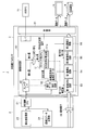
- FIG. 1 is a block diagram showing the configuration of an endoscope system including an image processing apparatus according to the first embodiment of the present invention.
- FIG. 2 is a block diagram showing a configuration of an endoscope system including the image processing apparatus according to the first embodiment, showing a configuration when receiving unique information from an external device and transmitting it to the endoscope.
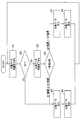
- FIG. 3 is a flowchart showing the rearrangement action of the scratch correction data for the 2D endoscopic image and the 3D endoscopic image in the image processing apparatus of the first embodiment.
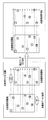
- FIG. 4 is an explanatory diagram showing how the image cutout position is changed and the scratch correction data is rearranged in the image processing apparatus according to the first embodiment.
- FIG. 1 is a block diagram showing the configuration of an endoscope system including an image processing apparatus according to the first embodiment of the present invention.
- an endoscope system 1 including an image processing apparatus includes an endoscope 2 that observes a subject and outputs a predetermined imaging signal (this embodiment will be described later).
- the endoscope 2 is assumed to be a so-called stereoscopic endoscope (3D endoscope) or a normal endoscope) and image processing of the present embodiment that enables the endoscope 2 to be connected.
- An endoscope processor 3 (hereinafter also referred to as a video processor 3) that is a device, a light source device (not shown) that supplies illumination light for illuminating a subject, and observation according to image data output from the video processor 3. It has a monitor 5 for displaying an image and a recording medium 6 for recording the image data output from the video processor 3.
- the endoscope 2 according to the present embodiment is a so-called stereoscopic endoscope (hereinafter referred to as a 3D endoscope) that generates a stereoscopic image using two captured images having parallax. ) And an ordinary endoscope that uses only one captured image (for convenience, referred to as a 2D endoscope).
- a 3D endoscope stereoscopic endoscope
- an ordinary endoscope that uses only one captured image for convenience, referred to as a 2D endoscope.
- the 3D endoscope includes a known insertion part that is inserted into the body cavity of the subject, and a pair of left and right imaging optical systems is provided at the tip of the insertion part. Further, at the image forming position of these image pickup optical systems, an image pickup section including an image pickup element 22 for receiving a pair of left and right images is provided. The image pickup unit outputs an image pickup signal for two picked-up images having parallax.
- the image pickup device 22 is composed of, for example, one CMOS image sensor.
- the light receiving unit of the image pickup device 22 has photodiodes that are a plurality of photoelectric conversion units that photoelectrically convert light according to incident light to generate signal charges, and based on the signal charges generated by the photoelectric conversion units. It has a plurality of pixels for generating and outputting an image pickup signal.
- the image pickup device 22 in the 3D endoscope is arranged at the image forming positions of the above-mentioned pair of image pickup optical systems, and a pair of left and right subject images are formed on the image pickup surface of one image pickup device. It is like this. Then, the light incident on each pixel corresponding to the left and right images is photoelectrically converted by the photoelectric conversion unit and a predetermined image pickup signal is output.
- the 2D endoscope is also provided with a known insertion portion or the like that is also inserted into the body cavity of the subject, and the distal end of the insertion portion is provided with a single-system imaging optical system.
- An image pickup section including an image pickup element 22 and the like is arranged at the image position.
- an image pickup signal relating to one picked-up image is output from this image pickup unit.
- the endoscope 2 is provided on the proximal end side of the insertion portion in addition to the elongated insertion portion to be inserted into the body cavity of the subject as described above, and is operated by the operator for grasping and operating. It is configured to have a mirror operating section and a universal cord having one end provided so as to extend from a side portion of the endoscope operating section.
- a connector portion connected to the light source device is provided on the proximal end side of the universal cord in the endoscope 2, and the endoscope CPU 21 for controlling various circuits in the endoscope is provided in the connector portion. It is arranged.
- the endoscope CPU 21 is formed of, for example, an FPGA (field-programmable gate array).
- an eccentricity amount storage section 23 that is controlled by the endoscope CPU 21 and stores eccentricity amount information of the image pickup optical system in the endoscope 2, and scratch correction data information related to the image pickup element 22 are provided. And a scratch correction data storage unit 24 to be stored.
- the endoscope 2 stores the eccentricity amount information related to the endoscope image as the unique information of the endoscope 2, and further, as the unique information of the endoscope 2, the flaw correction in the endoscope image is performed. It has the function of storing data information.
- eccentricity amount storage unit 23 and the flaw correction data storage unit 24 described above may be configured as one memory, for example, an ID memory that stores endoscope identification information of the endoscope 2.
- the “cutout function” is used to specify the coordinate position of the shifted pixel and selectively read only the pixel corresponding to the coordinate position. to correct.
- the “pixel shift” of the image pickup signal caused by the eccentricity of the image pickup optical system is inspected, that is, the degree of the pixel shift is
- the detected eccentricity information is stored in the eccentricity amount storage unit 23 as the eccentricity amount information of the image pickup optical system.
- the flaw correction data storage unit 24 is configured to store the flaw correction data information related to the image pickup device 22.
- the information regarding the “pixel shift” of the image pickup signal caused by the eccentricity of the image pickup optical system is stored in the storage unit (eccentricity amount storage unit 23) inside the endoscope. However, it may be stored in an external server or the like.
- the video processor 3 can connect the endoscope 2 of either the 3D endoscope or the 2D endoscope, and inputs the image pickup signal output from these endoscopes 2 to perform predetermined image processing. It has a function of applying and outputting.
- the video processor 3 when any of the endoscopes 2 is connected, inputs an image pickup signal from the endoscope 2 and performs predetermined image processing, and the image processing unit 30.
- the control unit 31 controls each circuit in the video processor 3.
- the image processing unit 30 includes a scope I / F 57 that transmits and receives predetermined data to and from the endoscope 2 connected to the video processor 3, and unique information (information such as an eccentricity amount) related to the endoscope 2.
- a processor-side CPU 51 that calculates the cut-out position coordinates of the image based on the image data, and a correction-data extraction circuit 52 that extracts and recalculates the correction data in the area corresponding to the cut-out position coordinates calculated by the processor-side CPU 51. Have.
- the image processing unit 30 cuts out an area corresponding to the cut-out position coordinates calculated by the processor-side CPU 51 from the endoscopic image received from the endoscope 2, an image cut-out circuit (first image cut-out circuit). 53, a second image cutout circuit 55) and a correction circuit (first scratch) for correcting the region cut out in the image cutout circuit in accordance with the correction data recalculated in the correction data extraction circuit 52.
- the correction circuit 54 and the second flaw correction circuit 56 ).
- the processor-side CPU 51 relates to the endoscopic image stored in the eccentricity storage unit 23 of the endoscope 2 via the scope I / F 57 when the endoscope 2 is connected to the video processor 3.
- the eccentricity amount information can be read.
- the processor-side CPU 51 together with the scope I / F 57, functions as a unique information reading unit that reads eccentricity amount information as unique information.
- the processor-side CPU 51 further includes a cutout position calculation circuit 51a.
- the cut-out position calculation circuit 51a generates an image based on the eccentricity amount information related to the endoscopic image read by the processor-side CPU 51 (in this case, the processor-side CPU 51 that functions as the unique information reading unit). Calculate the cutting position coordinates.
- the cut-out position calculation circuit 51a sends the calculated cut-out position coordinates to the correction data extraction circuit 52 in the subsequent stage, and also cuts out the cut-out position coordinates in the first image cut-out circuit 53 and / or the second image cut-out circuit 53.
- the image is output to the image cutout circuit 55.
- the first image cutout circuit 53 and the second image cutout circuit 55 correspond to the cutout position coordinates calculated by the processor-side CPU 51 with respect to the endoscopic image received from the endoscope 2.
- the cutout position calculation circuit 51a in the video processor 3 of the present embodiment has a plurality of cutouts corresponding to the left and right images. The coordinates related to the position can be calculated.
- the first image cutout circuit 53 calculates the cutout position calculation circuit 51a.
- the left image area is cut out in accordance with the cutout position related to the left image area.
- the second image cutout circuit 55 is for the right side calculated by the cutout position calculation circuit 51a.
- the right image area is cut out according to the cutout position related to the image area.
- the correction data extraction circuit 52 when the endoscope 2 is connected to the video processor 3, the scratch correction data relating to the endoscopic image stored in the scratch correction data storage unit 24 of the endoscope 2. Information can be read.
- the correction data extraction circuit 52 functions as a unique information reading unit that reads out flaw correction data information as unique information.
- the correction data extraction circuit 52 can read the flaw correction data information relating to the endoscope 2 connected as described above, but in the present embodiment, the correction data extraction circuit 52 uses the cutout position calculation circuit 51a. It has a function of extracting the scratch correction data in the area corresponding to the cut-out position coordinates calculated in step S3.
- the correction data extraction circuit 52 has a function of recalculating the scratch correction data in the target area according to the coordinates of the cutout position calculated by the cutout position calculation circuit 51a. Then, the correction data extraction circuit 52 sends the recalculated flaw correction data, that is, the coordinate-transformed flaw correction data to the first flaw correction circuit 54 and / or the second flaw correction circuit 56. There is.
- the first flaw correction circuit 54 and the second flaw correction circuit 56 correspond to the correction data recalculated in the correction data extraction circuit 52, that is, the flaw correction data after the cutting position coordinates are changed from the correction data extraction circuit 52. It is a correction circuit for performing the correction.
- the cutout position calculation circuit 51a in the video processor 3 causes the cutout position calculation circuit 51a to detect a plurality of cutouts corresponding to the left and right images.
- the coordinates relating to the extraction position are calculated, and the respective calculation results are output.
- the correction data extraction circuit 52 that receives them calculates the left and right corresponding to the left and right cutting position coordinates calculated in the cutting position calculation circuit 51a.
- the correction data in each area is extracted.
- the correction data extraction circuit 52 outputs the correction data of the left and right images extracted by the correction data extraction circuit 52 to the left and right images. Recalculation is performed based on the cut-out position coordinates of.
- the first flaw correction circuit 54 further relates to the left image area calculated by the cut-out position calculation circuit 51a.
- the correction data extracting circuit 52 performs correction corresponding to the recalculated scratch correction data according to the output position, and sends the corrected image data to the monitor 5 or the recording medium 6.
- the second flaw correction circuit 56 similarly calculates the right image calculated by the cutout position calculation circuit 51a.
- a correction corresponding to the flaw correction data recalculated in the correction data extraction circuit 52 is performed according to the cutout position related to the area, and the corrected image data is sent to the monitor 5 or the recording medium 6.
- the video processor 3 has a control unit 31 as shown in FIGS.
- the control unit 31 has a function of controlling each circuit in the video processor 3 in addition to the image processing unit 30.
- an external device for example, an external PC 71 to be described later
- the external PC 71 outputs predetermined specific information regarding a predetermined endoscope.
- it is receivable and has received the unique information, it also has a function of instructing the cutout position calculation circuit 51a to change the cutout position coordinates of the image based on the unique information.
- FIG. 2 is a block diagram showing a configuration of an endoscope system including the image processing apparatus according to the first embodiment, showing a configuration when receiving unique information from an external device and transmitting it to the endoscope.
- FIG. 2 is a block diagram showing a configuration of an endoscope system including the image processing apparatus according to the first embodiment, showing a configuration when receiving unique information from an external device and transmitting it to the endoscope.
- the video processor 3 in the endoscope system 1 includes a control unit 31 that performs control of receiving unique information from an external PC (personal computer) 71 and transmitting the unique information to the endoscope 2.
- a control unit 31 that performs control of receiving unique information from an external PC (personal computer) 71 and transmitting the unique information to the endoscope 2.
- information unique to each endoscope 2 is previously stored in an external device ( It is stored in the external PC 71).
- the external PC 71 When adjusting the factory of the endoscope 2, first, the external PC 71 is connected to the external PC interface of the video processor 3 set to the jig mode, and is controlled by the external PC 71 or a control unit in the video processor 3. Under the control of 31, the unique information related to the endoscope 2 stored in the external PC 71 (for example, the eccentricity amount information and the flaw correction data information regarding the endoscope 2, which are separately acquired) is processed by the processor side of the video processor 3. The process moves to the CPU 51.
- the endoscope 2 is connected to the scope I / F 57 of the video processor 3, and under the control of the control unit 31, the unique information (eccentricity amount information, flaw correction data information, etc.) relating to the endoscope 2 that has moved to the processor-side CPU 51. ) Is written in the eccentricity amount storage unit 23 or the flaw correction data storage unit 24 in the endoscope 2.
- the unique information (eccentricity amount information, flaw correction data information, etc.) related to the endoscope 2 is stored in a predetermined storage unit of the endoscope 2.
- the video processor 3 set to the jig mode at the time of factory adjustment of the endoscope is connected to the external PC 71, and the unique information about the endoscope 2 stored in the external PC. Is temporarily transferred to the video processor 3 as a jig, and further, this unique information is transferred from the video processor 3 to the endoscope 2 and is written in the storage unit of the endoscope 2. Not limited to this, the same writing process may be performed using a predetermined jig other than the video processor 3.
- the service person uses the video processor 3 or the predetermined jig set in the jig mode as described above, and the same unique information as described above. It is also possible to perform a writing process.
- the processor-side CPU 51 of the image processing unit 30 causes the scratch correction data storage unit 24 of the endoscope 2 to operate.
- the stored information on the flaw correction data relating to the endoscope 2 is read out.
- the processor-side CPU 51 further reads the information on the eccentricity amount related to the endoscope 2 stored in the eccentricity amount storage unit 23.
- the processor-side CPU 51 calculates the cut-out position coordinates of the image based on the eccentricity amount information read from the endoscope 2 by the cut-out position calculation circuit 51a in the processor-side CPU 51, and calculates the calculated cut-out position coordinates. , To the correction data extraction circuit 52 in the subsequent stage.
- cutout position calculation circuit 51a sends the calculated cutout position coordinates to the first image cutout circuit 53 and / or the second image cutout circuit 55.
- the correction data extraction circuit 52 in the image processing unit 30 converts the endoscopic image stored in the flaw correction data storage unit 24 of the endoscope 2 into the endoscopic image.
- the flaw correction data information is read out.
- correction data extraction circuit 52 extracts the flaw correction data in the area corresponding to the cut-out position coordinates calculated by the cut-out position calculation circuit 51a, and further, the flaw in the target area according to the cut-out position coordinates. Recalculation of correction data, that is, coordinate conversion is performed.
- the correction data extraction circuit 52 sends the recalculated flaw correction data, that is, the coordinate-transformed flaw correction data to the first flaw correction circuit 54 and / or the second flaw correction circuit 56.
- the correction data extraction circuit 52 converts, for example, the scratch correction data relating to the first scratch correction circuit 54 into a coordinate position in consideration of the cutout position in the first image cutout circuit 53. Then, the coordinate-transformed flaw correction data is distributed to the first flaw correction circuit 54.
- the correction data extraction circuit 52 converts the scratch correction data related to the second scratch correction circuit 56 into a coordinate position in consideration of the cut-out position in the second image cut-out circuit 55, and the coordinate-corrected scratch correction is performed. The data is distributed to the second flaw correction circuit 56.
- the correction data extraction circuit 52 rearranges the pixels so that the image processing circuit in the subsequent stage can easily process the pixels.
- the endoscope 2 connected to the video processor 3 is a 3D endoscope as described above, in the case of two-screen scratch correction data, the raster scan order of the scratch correction data is rearranged.
- FIG. 3 is a flow chart showing the rearrangement action of the flaw correction data for the 2D endoscopic image and the 3D endoscopic image in the image processing apparatus of the first embodiment, and FIG. 4 of the first embodiment.
- FIG. 8 is an explanatory diagram showing a state of changing the cutout position of images and rearranging the scratch correction data in the image processing apparatus.
- the correction data extraction circuit 52 in the video processor 3 firstly, in the raster scan order, the scratch correction data related to the left image processing area corresponding to the cutout position in the first image cutout circuit 53. (Left scratch correction data) is read (step S1).
- step S2 when the endoscope 2 connected to the video processor 3 is the two-screen 3D endoscope as described above (step S2), it corresponds to the cutout position in the second image cutout circuit 53.
- the flaw correction data (right flaw correction data) relating to the right image processing area is read (step S3).
- the correction data extraction circuit 52 compares the Y coordinates on the screen (step S4), When the Y coordinate in the left flaw correction data ⁇ the Y coordinate in the right flaw correction data image, the left flaw correction data is output to the first flaw correction circuit 54 (step S5). At this time, unused data in the left image processing area is discarded (see FIG. 4).
- the correction data extraction circuit 52 requests the left scratch correction data again (step S6), returns to step S1, and again, in raster scan order, acquires the scratch correction data (left scratch correction data) related to the left image processing area. Read out (step S1).
- the correction data extraction circuit 52 outputs the right flaw correction data to the second flaw correction circuit 56 (step S7). ). At this time, unused data in the right image processing area is discarded (see FIG. 4).
- the correction data extraction circuit 52 requests the right scratch correction data again (step S8), returns to step S1, and again, in raster scan order, acquires the scratch correction data (left scratch correction data) relating to the left image processing area. Read out (step S1).
- step S2 when the endoscope 2 connected to the video processor 3 is a so-called 1-screen 2D endoscope, it is not necessary to compare left and right images, and the first flaw correction circuit 54 is left scratched.
- the correction data (for convenience, referred to as left scratch correction data, which is the scratch correction data of the region corresponding to the cut position in the first image cutout circuit 53) is output, and again in the first image cutout circuit 53. Requesting the scratch correction data of the area corresponding to the cutout position (step S6), the process returns to step S1.
- the external PC 71 is connected to the external PC interface of the video processor 3, and under the control of the control unit 31, the unique information (eccentricity) related to the endoscope 2 stored in the external PC 71 is stored. Quantity information, flaw correction data information, etc.) is transferred to the processor side CPU 51 in the video processor 3.
- control unit 31 transmits an eccentricity amount calculation instruction, that is, a cutout position change instruction to the processor side CPU 51 (cutout position calculation circuit 51a).
- processor side CPU 51 cutout position calculation circuit 51a
- the processor-side CPU 51 recalculates the cutout position, and sends new cutout position coordinate information to the correction data extraction circuit 52. Since the subsequent operation is as described above, the description here is omitted.
- the image processing apparatus of this embodiment it is possible to prevent an increase in the amount of data and the circuit scale for correcting the scratches on the image sensor.
Landscapes
- Health & Medical Sciences (AREA)
- Life Sciences & Earth Sciences (AREA)
- Surgery (AREA)
- Biomedical Technology (AREA)
- Medical Informatics (AREA)
- Optics & Photonics (AREA)
- Pathology (AREA)
- Radiology & Medical Imaging (AREA)
- Biophysics (AREA)
- Engineering & Computer Science (AREA)
- Physics & Mathematics (AREA)
- Heart & Thoracic Surgery (AREA)
- Nuclear Medicine, Radiotherapy & Molecular Imaging (AREA)
- Molecular Biology (AREA)
- Animal Behavior & Ethology (AREA)
- General Health & Medical Sciences (AREA)
- Public Health (AREA)
- Veterinary Medicine (AREA)
- Endoscopes (AREA)
- Instruments For Viewing The Inside Of Hollow Bodies (AREA)
Abstract
内視鏡2の偏心量記憶部23から読み出した偏心量情報に基づいて画像の切出位置座標を計算する切出位置計算回路51aと、切出位置計算回路51aにおいて計算された切出位置座標に対応した領域における補正データを抽出すると共に当該切出位置座標に基づいて再計算する補正データ抽出回路52と、内視鏡2から受信した内視鏡画像に対して、補正データ抽出回路52において計算した切出位置座標に対応した領域を切り出す画像切出回路(第1画像切出回路53、第2画像切出回路55)と、画像切出回路において切り出した領域に対して、補正データ抽出回路52において再計算した補正データに対応した補正を施す補正回路(第1傷補正回路54、第2傷補正回路56)と、を具備する。
Description
本発明は、画像処理装置および内視鏡システム、特に、内視鏡に格納された撮像素子の傷補正データを読み込み、内視鏡画像の補正を行う画像処理装置および内視鏡システムに関する。
被検体の内部の被写体を撮像する内視鏡、及び、内視鏡により撮像された被写体の観察画像を生成する画像処理装置等を具備する内視鏡システムが、医療分野及び工業分野等において広く用いられている。
この種の内視鏡システムにおいては、従来、搭載する撮像素子に対し傷補正等の各種補正のための補正データ等の情報を個別に格納する内視鏡、および当該内視鏡を接続する画像処理装置(ビデオプロセッサ)を含む内視鏡システムが知られるようになっている。
ここで、当該内視鏡を接続する画像処理装置(ビデオプロセッサ)は、内視鏡が接続される際に当該内視鏡に格納された情報(傷補正データ等)を読み込み、当該傷補正データに応じて画像全体の各種補正を行うようになっている。
しかしながら従来の内視鏡システムにおいては、前記ビデオプロセッサは、接続される内視鏡に格納された全補正データを受信し、当該ビデオプロセッサ内に保持し、この全補正データに基づいて内視鏡画像全体の補正処理を行っていた。
ところで近年、内視鏡に搭載される撮像素子は益々高画素数化および微細化が進み、これに伴い、内視鏡に格納される傷補正データ等の補正データの数および種類は増加の一途を辿っている。すなわち、上述したようにビデオプロセッサ側において内視鏡に格納される全補正データを保持し、内視鏡画像全体の補正処理を行うシステムでは、搭載するメモリまたは処理回路等の規模が大型化し、コストも増大することとなる。
一方、内視鏡の分野においても、撮像光学系の偏心に起因する撮像信号の画素ずれ、または、複数の撮像素子を用いた、いわゆる3D内視鏡システム(たとえば、3D撮像システムもしくはプリズムで光学像を分離し2つ以上の撮像素子で受光する3CCDの如き撮像システムを用いた3D内視鏡システム)において各撮像素子間の位置ずれを電気的に補正する技術が知られている。
この種の補正技術としては、たとえば、日本国特開2006-239052号公報等において、撮像素子における任意範囲の画素のみを選択的に読み出す「切り出し機能」を用い、上記画素ずれの補正を実現する技術が知られている。
このような「切り出し機能」を用いた内視鏡システムにおいて、例えば上述した如く撮像素子の傷補正を行う場合、傷補正に関しても切り出した領域のみを適正に補正すれば有効であるが、従来の内視鏡システムでは、上述した如くビデオプロセッサ側において内視鏡に格納される全補正データを保持し、内視鏡画像全体の補正処理を行うため、やはり、搭載するメモリまたは処理回路規模の大型化、コストの増大化は避けられなかった。
本発明は上述した事情に鑑みてなされたものであり、撮像素子の傷補正をするためのデータ量および回路規模の増大化を防ぐことができる画像処理装置および内視鏡システムを提供することを目的とする。
本発明の一態様の画像処理装置は、内視鏡に記憶された当該内視鏡に係る所定の固有情報を読み出す固有情報読出部と、前記固有情報読出部において読み出した前記固有情報に基づいて画像の切出位置座標を計算する画像切出位置計算部と、前記画像切出位置計算部において計算された前記切出位置座標に対応した領域における補正データを抽出する補正データ抽出部と、前記補正データ抽出部において抽出された前記補正データを、当該切出位置座標に基づいて再計算する補正データ再計算部と、内視鏡から受信した内視鏡画像に対して、前記画像切出位置計算部において計算した切出位置座標に対応した領域を切り出す画像切出回路と、前記画像切出回路において切り出した領域に対して、前記補正データ再計算部において再計算した前記補正データに対応した補正を施す補正回路と、を具備する。
また、本発明の一態様の内視鏡システムは、前記画像処理装置であって、外部機器から所定の内視鏡に係る所定の固有情報を受信可能であって、当該固有情報を受信した際、前記画像切出位置計算部に対して、当該固有情報に基づいて画像の切出位置座標を変更するよう指示する制御部をさらに有し、前記制御部は、前記固有情報を当該所定の内視鏡に送信する画像処理装置と、前記制御部から送信される前記固有情報を記憶する記憶部を有する内視鏡と、を具備する。
以下、本発明の実施の形態について図面を用いて説明する。
<第1の実施形態>
図1は、本発明の第1の実施形態に係る画像処理装置を含む内視鏡システムの構成を示すブロック図である。
図1は、本発明の第1の実施形態に係る画像処理装置を含む内視鏡システムの構成を示すブロック図である。
図1に示すように、本第1の実施形態に係る画像処理装置を含む内視鏡システム1は、被検体を観察し所定の撮像信号を出力する内視鏡2(後述するように本実施形態において内視鏡2は、いわゆる立体内視鏡(3D内視鏡)と通常の内視鏡とのいずれか想定する)と、当該内視鏡2を接続可能とする本実施形態の画像処理装置である内視鏡プロセッサ3(以下、ビデオプロセッサ3とも記す)と、被検体を照明するための照明光を供給する図示しない光源装置と、ビデオプロセッサ3から出力された画像データに応じた観察画像を表示するモニタ5と、ビデオプロセッサ3から出力された画像データを記録する記録媒体6と、を有している。
本実施形態の画像処理装置に内視鏡2は、本実施形態においては、視差を有する2つの撮像画像を用いて立体画像を生成する、いわゆる立体内視鏡(以下、3D内視鏡と称す)と、1つの撮像画像のみを用いる通常の内視鏡(便宜上、2D内視鏡と称す)と、のいずれかの内視鏡を想定する。
前記3D内視鏡は、被検体の体腔内に挿入される公知の挿入部等を備え、当該挿入部の先端には、左右一対の撮像光学系を備える。また、これら撮像光学系の結像位置には左右一対の像を受光する撮像素子22等により構成された撮像部が配設されている。この撮像部からは視差を有する2つの撮像画像に係る撮像信号が出力されるようになっている。
前記撮像素子22は、例えば、1枚のCMOSイメージセンサにより構成される。この撮像素子22における受光部は、入射光に応じて光を光電変換して信号電荷を生成する複数の光電変換部であるフォトダイオードを有し、当該光電変換部において生成した信号電荷に基づいて撮像信号を生成し出力するための複数の画素を備える。
本実施形態において3D内視鏡における撮像素子22は、上述した一対の撮像光学系の結像位置に配設され、1枚の撮像素子の撮像面上に左右一対の被写体像が結像されるようになっている。そして、それぞれ左右画像に対応する各画素に入射した光を光電変換部において光電変換して所定の撮像信号を出力するようになっている。
一方、前記2D内視鏡は、同じく被検体の体腔内に挿入される公知の挿入部等を備え、当該挿入部の先端には、1系統の撮像光学系を備え、この撮像光学系の結像位置には撮像素子22等により構成された撮像部が配設されている。また、この撮像部からは1つの撮像画像に係る撮像信号が出力されるようになっている。
また内視鏡2は、上述したように被検体の体腔内等に挿入される細長の挿入部の他に、挿入部の基端側に配設され術者が把持して操作を行う内視鏡操作部と、当該内視鏡操作部の側部から延出するように一方の端部が設けられたユニバーサルコードと、を有して構成されている。
さらに内視鏡2における前記ユニバーサルコードの基端側には、前記光源装置に接続されるコネクタ部が設けられ、当該コネクタ部には、内視鏡における各種回路を制御する内視鏡側CPU21が配設される。なお、この内視鏡側CPU21は、例えば、FPGA(field-programmable gate array)等により形成される。
さらに当該コネクタ部には、前記内視鏡側CPU21に制御され、当該内視鏡2における撮像光学系の偏心量情報を記憶する偏心量記憶部23と、撮像素子22に係る傷補正データ情報を記憶する傷補正データ記憶部24と、を有する。
ここで内視鏡2は、当該内視鏡2の固有情報として、内視鏡画像に係る偏心量情報を記憶し、さらに、当該内視鏡2の固有情報として、内視鏡画像における傷補正データの情報を記憶する機能と有する。
なお、上述した偏心量記憶部23と傷補正データ記憶部24とは、1つのメモリ、例えば、当該内視鏡2における内視鏡固別情報を記憶したIDメモリとして構成されてもよい。
<撮像信号の画素ずれについて>
ここで、本実施形態における「画素ずれの検出」および「画素ずれに係る情報の記憶」について説明する。上述したように、撮像光学系の偏心等に起因して撮像信号の「画素ずれ」が生じることがある。この「画素ずれ」が生じたとき、何等対策を講じずそのまま画像信号を読み出す処理等を行うと、当然ながら、モニタに表示される画像は「画素ずれ」の度合いに応じてずれてしまうこととなり、正確な画像を表示することができない虞がある。
ここで、本実施形態における「画素ずれの検出」および「画素ずれに係る情報の記憶」について説明する。上述したように、撮像光学系の偏心等に起因して撮像信号の「画素ずれ」が生じることがある。この「画素ずれ」が生じたとき、何等対策を講じずそのまま画像信号を読み出す処理等を行うと、当然ながら、モニタに表示される画像は「画素ずれ」の度合いに応じてずれてしまうこととなり、正確な画像を表示することができない虞がある。
特に、本実施形態において採用する、1枚の撮像素子の撮像面上に1対の撮像光学系からの被写体像を左右画像として結像する3D内視鏡においては、1対の撮像光学系の偏心の影響をより大きく受けることとなる。
このように、撮像光学系の偏心等に起因して撮像信号の「画素ずれ」が生じた場合、または「画素ずれ」が生じた内視鏡の場合、正確な画像を表示することができない虞があるが、本実施形態においては、「画素ずれ」が生じた際、当該ずれた画素の座標位置を特定し、その座標位置に対応した画素のみを選択的に読み出す「切り出し機能」を用いて補正する。
そして本実施形態においては、画素ずれ補正の前提として、例えば内視鏡の製造時等において、撮像光学系の偏心等に起因する撮像信号の「画素ずれ」を検査し、すなわち画素ずれの度合いを検出し、その画素ずれの度合いに応じた情報を撮像光学系の偏心量情報として偏心量記憶部23に記憶するようになっている。
一方このとき、傷補正データ記憶部24には、撮像素子22に係る傷補正データ情報が記憶されるようになっている。
なお、本実施形態においては、撮像光学系の偏心等に起因する撮像信号の「画素ずれ」に係る情報を内視鏡内部の記憶部(偏心量記憶部23)に記憶するものとしたがこれに限らず、外部のサーバー等に記憶するようしてもよい。
次に、ビデオプロセッサ3は、前記3D内視鏡または2D内視鏡のいずれかの内視鏡2を接続可能とし、これら内視鏡2から出力された撮像信号を入力し所定の画像処理を施して出力する機能を有する。
具体的にビデオプロセッサ3は、前記いずれかの内視鏡2が接続された際、当該内視鏡2から撮像信号を入力し所定の画像処理を施す画像処理部30と、当該画像処理部30のほかビデオプロセッサ3内の各回路を制御する制御部31と、を有する。
画像処理部30は、ビデオプロセッサ3に接続された内視鏡2との間で所定のデータの送受を行うスコープI/F57と、内視鏡2に係る固有情報(偏心量等の情報)に基づいて画像の切出位置座標を計算するプロセッサ側CPU51と、当該プロセッサ側CPU51において計算された前記切出位置座標に対応した領域における補正データを抽出し再計算する補正データ抽出回路52と、を有する。
さらに画像処理部30は、内視鏡2から受信した内視鏡画像に対して、前記プロセッサ側CPU51において計算した切出位置座標に対応した領域を切り出す画像切出回路(第1画像切出回路53、第2画像切出回路55)と、前記画像切出回路において切り出した領域に対して、前記補正データ抽出回路52において再計算した前記補正データに対応した補正を施す補正回路(第1傷補正回路54、第2傷補正回路56)と、を有する。
前記プロセッサ側CPU51は、ビデオプロセッサ3に内視鏡2が接続された際、スコープI/F57を経由して当該内視鏡2の偏心量記憶部23に記憶された前記内視鏡画像に係る偏心量情報を読み出し可能である。
すなわち、プロセッサ側CPU51は、スコープI/F57と共に、固有情報としての偏心量情報を読み出す固有情報読出部としての機能を果たす。
さらにプロセッサ側CPU51は、切出位置計算回路51aを備える。この当該切出位置計算回路51aは、当該プロセッサ側CPU51(この場合、前記固有情報読出部としての機能を果たすプロセッサ側CPU51)において読み出した前記内視鏡画像に係る偏心量情報に基づいて画像の切出位置座標を計算する。
この切出位置計算回路51aは、計算した切出位置座標を、後段の補正データ抽出回路52に向けて送出すると共に、当該切出位置座標を、第1画像切出回路53および/または第2画像切出回路55に向けて送出するようになっている。
前記第1画像切出回路53および前記第2画像切出回路55は、いずれも内視鏡2から受信した内視鏡画像に対して、前記プロセッサ側CPU51において計算した切出位置座標に対応した領域を切り出す画像切出回路である。
ここで、本実施形態のビデオプロセッサ3における切出位置計算回路51aは、ビデオプロセッサ3に接続された内視鏡2が上述の如き3D内視鏡の場合、左右画像に対応する複数の切出位置に係る座標を計算可能である。
本実施形態においては、例えば、ビデオプロセッサ3に接続された内視鏡2が上述の如き3D内視鏡の場合、前記第1画像切出回路53は、前記切出位置計算回路51aにおいて計算した左用の画像領域に係る切出位置に応じて、左画像領域を切り出す。
一方、第2画像切出回路55は、同様に、ビデオプロセッサ3に接続された内視鏡2が上述の如き3D内視鏡である場合、前記切出位置計算回路51aにおいて計算した右用の画像領域に係る切出位置に応じて、右用の画像領域を切り出す。
また、前記補正データ抽出回路52は、ビデオプロセッサ3に内視鏡2が接続された際、当該内視鏡2の傷補正データ記憶部24に記憶された前記内視鏡画像に係る傷補正データ情報を読み出し可能である。
すなわち、補正データ抽出回路52は、固有情報としての傷補正データ情報を読み出す固有情報読出部としての機能を果たす。
また補正データ抽出回路52は、上述したように接続された内視鏡2に係る傷補正データ情報を読み出し可能であるが、本実施形態において補正データ抽出回路52は、前記切出位置計算回路51aにおいて計算された前記切出位置座標に対応した領域における傷補正データを抽出する機能を有する。
さらに補正データ抽出回路52は、切出位置計算回路51aにおいて計算された前記切出位置の座標に応じて対象領域における傷補正データの再計算を行う機能を有する。そして補正データ抽出回路52は、再計算した傷補正データ、すなわち、座標変換後の傷補正データを、第1傷補正回路54および/または第2傷補正回路56に向けて送出するようになっている。
第1傷補正回路54および第2傷補正回路56は、前記補正データ抽出回路52において再計算された前記補正データ、すなわち、補正データ抽出回路52から切出位置座標変更後の傷補正データに対応した補正を施す補正回路である。
ここで、上述したように、ビデオプロセッサ3に接続された内視鏡2が上述の如き3D内視鏡の場合、ビデオプロセッサ3における切出位置計算回路51aは、左右画像に対応する複数の切出位置に係る座標を計算し、それぞれ計算結果を出力するが、これを受けた補正データ抽出回路52は、前記切出位置計算回路51aにおいて計算された左右の切出位置座標に対応した左右の領域における補正データをそれぞれ抽出する。
またビデオプロセッサ3に接続された内視鏡2が上述の如き3D内視鏡の場合、補正データ抽出回路52は、当該補正データ抽出回路52においてそれぞれ抽出した前記左右画像の補正データを、前記左右の切出位置座標に基づいてそれぞれ再計算するようになっている。
さらに、第1傷補正回路54は、ビデオプロセッサ3に接続された内視鏡2が上述の如き3D内視鏡である場合、前記切出位置計算回路51aにおいて計算した左用の画像領域に係る切出位置に応じて、前記補正データ抽出回路52において再計算された傷補正データに対応した補正を施し、補正した画像データをモニタ5または記録媒体6に向けて送出する。
一方、第2傷補正回路56は、同様に、ビデオプロセッサ3に接続された内視鏡2が上述の如き3D内視鏡である場合、前記切出位置計算回路51aにおいて計算した右用の画像領域に係る切出位置に応じて、前記補正データ抽出回路52において再計算された傷補正データに対応した補正を施し、補正した画像データをモニタ5または記録媒体6に向けて送出する。
さらにビデオプロセッサ3は、図1、図2に示すように制御部31を有する。制御部31は、上述したように、画像処理部30のほかビデオプロセッサ3内の各回路を制御する機能を有する。例えば、内視鏡2の工場での調整時においてビデオプロセッサ3に外部機器(例えば、後述する外部PC71等)が接続された際、当該外部PC71から所定の内視鏡に係る所定の固有情報を受信可能であって当該固有情報を受信した際、前記切出位置計算回路51aに対して、当該固有情報に基づいて画像の切出位置座標を変更するよう指示する機能も有する。
<内視鏡の工場調整時>
次に、本実施形態の画像処理装置(ビデオプロセッサ3)および内視鏡を含む内視鏡システムにおいて、工場調整時において稼働する構成および調整時の作用について説明する。
次に、本実施形態の画像処理装置(ビデオプロセッサ3)および内視鏡を含む内視鏡システムにおいて、工場調整時において稼働する構成および調整時の作用について説明する。
図2は、第1の実施形態の画像処理装置を含む内視鏡システムの構成を示すブロック図であって、外部機器から固有情報を受信し内視鏡に向けて送信する際の構成を示したブロック図である。
図2に示すように、内視鏡システム1におけるビデオプロセッサ3は、外部PC(パーソナルコンピュータ)71から固有情報を受信し内視鏡2に向けて送信する制御を行う制御部31と、備える。
また、本実施形態のビデオプロセッサ3および内視鏡2を含む内視鏡システム1においては、各内視鏡2における固有の情報(偏心量情報、傷補正データ情報等)が、予め外部機器(外部PC71)に格納されている。
そして内視鏡2の工場調整時においては、まず、冶具モードに設定されたビデオプロセッサ3の外部PC用インターフェースに外部PC71を接続し、当該外部PC71の制御下、または、ビデオプロセッサ3における制御部31の制御下に、当該外部PC71に格納された内視鏡2に係る固有情報(例えば、別途取得した当該内視鏡2に関する偏心量情報、傷補正データ情報等)をビデオプロセッサ3におけるプロセッサ側CPU51に移行する。
さらにビデオプロセッサ3のスコープI/F57に内視鏡2を接続し、制御部31の制御下に、プロセッサ側CPU51に移行した内視鏡2に係る固有情報(偏心量情報、傷補正データ情報等)を内視鏡2における偏心量記憶部23または傷補正データ記憶部24に書き込む。
これにより、当該内視鏡2に係る固有情報(偏心量情報、傷補正データ情報等)が、内視鏡2における所定の記憶部に格納されることになる。
なお本実施形態では、上述したように、内視鏡の工場調整時において冶具モードに設定されたビデオプロセッサ3を外部PC71に接続し、当該外部PCに格納された内視鏡2に係る固有情報を冶具としてのビデオプロセッサ3に一旦移行し、さらに、ビデオプロセッサ3から内視鏡2に対してこの固有情報を移行し、当該内視鏡2における上記記憶部に書き込むようにしたが、これらに限らず、ビデオプロセッサ3以外の所定の冶具を用いて同様の書き込み処理を行うようにしても良い。
また、内視鏡の工場調整時に限らず、内視鏡2の出荷後においても、例えばサービスマンが上述の如く冶具モードに設定されたビデオプロセッサ3または所定の冶具を用いて上記同様の固有情報書き込み処理を行うことも可能である。
<内視鏡の通常使用時>
次に、ビデオプロセッサ3に上述の如き固有情報が格納された内視鏡2が接続された際の作用について説明する。
次に、ビデオプロセッサ3に上述の如き固有情報が格納された内視鏡2が接続された際の作用について説明する。
ビデオプロセッサ3の画像処理部30は、内視鏡2がスコープI/F57に接続されたことを認識すると、画像処理部30におけるプロセッサ側CPU51が、内視鏡2の傷補正データ記憶部24に格納されている当該内視鏡2に係る傷補正データの情報を読み出す。プロセッサ側CPU51は、さらに、偏心量記憶部23に格納されている当該内視鏡2に係る偏心量の情報を読み出す。
この後プロセッサ側CPU51は、当該プロセッサ側CPU51における切出位置計算回路51aが、内視鏡2から読み出した偏心量情報に基づいて画像の切出位置座標を計算し、計算した切出位置座標を、後段の補正データ抽出回路52に向けて送出する。
さらに切出位置計算回路51aは、計算した切出位置座標を、第1画像切出回路53および/または第2画像切出回路55に向けて送出する。
一方、画像処理部30における補正データ抽出回路52は、ビデオプロセッサ3に内視鏡2が接続された際、当該内視鏡2の傷補正データ記憶部24に記憶された前記内視鏡画像に係る傷補正データ情報を読み出す。
また補正データ抽出回路52は、前記切出位置計算回路51aにおいて計算された前記切出位置座標に対応した領域における傷補正データを抽出し、さらに、当該切出位置座標に応じて対象領域における傷補正データの再計算、すなわち、座標変換を行う。
その後補正データ抽出回路52は、再計算した傷補正データ、すなわち、座標変換後の傷補正データを、第1傷補正回路54および/または第2傷補正回路56に向けて送出する。
ここで補正データ抽出回路52は、例えば、第1傷補正回路54に係る傷補正データに関しては、前記第1画像切出回路53における切出位置を考慮した座標位置に変換する。そして、座標変換された傷補正データは、当該第1傷補正回路54に分配される。
同様に補正データ抽出回路52は、第2傷補正回路56に係る傷補正データに関しては、前記第2画像切出回路55における切出位置を考慮した座標位置に変換し、座標変換された傷補正データは、当該第2傷補正回路56に分配される。
前記補正データ抽出回路52は、さらに後段の画像処理回路において処理しやすいように、画素の並べ替えを行う。
例えば、ビデオプロセッサ3に接続される内視鏡2が上述した如き3D内視鏡である場合等、2画面の傷補正データの場合、当該傷補正データにおけるラスタースキャン順の並べ替えを行う。
図3は、第1の実施形態の画像処理装置において2D内視鏡画像および3D内視鏡画像に対する傷補正データの並び替え作用を示したフローチャートであり、図4は、第1の実施形態の画像処理装置において画像の切出位置変更と傷補正データの並び替えの様子を示した説明図である。
なお、説明の便宜上、ビデオプロセッサ3に接続される内視鏡2が上述した如き3D内視鏡である場合を主として説明する。
図3、図4に示すように、ビデオプロセッサ3における補正データ抽出回路52は、まず、ラスタースキャン順に、第1画像切出回路53における切出位置に相当する左画像処理領域に係る傷補正データ(左傷補正データ)を読み出す(ステップS1)。
ここで、ビデオプロセッサ3に接続される内視鏡2が上述した如き2画面の3D内視鏡である場合(ステップS2)、次に、第2画像切出回路53における切出位置に相当する右画像処理領域に係る傷補正データ(右傷補正データ)の読み出す(ステップS3)。
次に補正データ抽出回路52は、画面上のY座標を比較し(ステップS4)、
左傷補正データにおけるY座標≦右傷補正データ画像におけるY座標
の場合、第1傷補正回路54に対して左傷補正データを出力する(ステップS5)。なお、このとき、左画像処理領域における未使用データは破棄される(図4参照)。
左傷補正データにおけるY座標≦右傷補正データ画像におけるY座標
の場合、第1傷補正回路54に対して左傷補正データを出力する(ステップS5)。なお、このとき、左画像処理領域における未使用データは破棄される(図4参照)。
この後補正データ抽出回路52は、左傷補正データを再度要求して(ステップS6)、ステップS1に戻り、再び、ラスタースキャン順に、左画像処理領域に係る傷補正データ(左傷補正データ)を読み出す(ステップS1)。
一方、ステップS4において
左傷補正データにおけるY座標>右傷補正データ画像におけるY座標
の場合、補正データ抽出回路52は、第2傷補正回路56に対して右傷補正データを出力する(ステップS7)。なお、このとき、右画像処理領域における未使用データは破棄される(図4参照)。
左傷補正データにおけるY座標>右傷補正データ画像におけるY座標
の場合、補正データ抽出回路52は、第2傷補正回路56に対して右傷補正データを出力する(ステップS7)。なお、このとき、右画像処理領域における未使用データは破棄される(図4参照)。
この後補正データ抽出回路52は、右傷補正データを再度要求して(ステップS8)、ステップS1に戻り、再び、ラスタースキャン順に、左画像処理領域に係る傷補正データ(左傷補正データ)を読み出す(ステップS1)。
またステップS2において、ビデオプロセッサ3に接続される内視鏡2が、いわゆる1画面の2D内視鏡である場合、左右画像を比較する必要もなく、第1傷補正回路54に対して左傷補正データ(便宜上、左傷補正データと記すが、第1画像切出回路53における切出位置に相当する領域の傷補正データである)を出力し、再度、当該第1画像切出回路53における切出位置に相当する領域の傷補正データを要求して(ステップS6)、ステップS1に戻る。
<偏心量の再設定の場合>
次に、本実施形態の画像処理装置(ビデオプロセッサ3)および内視鏡を含む内視鏡システムにおいて、工場調整時もしくはモード切替時等において、撮像光学系の偏心量が変更された場合、または、画像サイズが変更された場合等においては、切出位置を再計算する必要がある。
次に、本実施形態の画像処理装置(ビデオプロセッサ3)および内視鏡を含む内視鏡システムにおいて、工場調整時もしくはモード切替時等において、撮像光学系の偏心量が変更された場合、または、画像サイズが変更された場合等においては、切出位置を再計算する必要がある。
この場合、図2に示すように、ビデオプロセッサ3の外部PC用インターフェースに外部PC71を接続し、制御部31の制御下に、当該外部PC71に格納された内視鏡2に係る固有情報(偏心量情報、傷補正データ情報等)をビデオプロセッサ3におけるプロセッサ側CPU51に移行する。
次に制御部31は、プロセッサ側CPU51(切出位置計算回路51a)に対して偏心量計算指示、すなわち、切出位置変更指示を送信する。プロセッサ側CPU51(切出位置計算回路51a)は、当該指示を受信すると切出位置を再計算し、新たな切出位置座標情報を補正データ抽出回路52に向けて送出する。その後の作用は、上述したとおりであるので、ここでの説明は省略する。
以上説明したように本実施形態の画像処理装置によると、撮像素子の傷補正をするためのデータ量および回路規模の増大化を防ぐことができる。
本発明は、上述した実施形態に限定されるものではなく、本発明の要旨を変えない範囲において、種々の変更、改変等が可能である。
Claims (6)
- 内視鏡に記憶された当該内視鏡に係る所定の固有情報を読み出す固有情報読出部と、
前記固有情報読出部において読み出した前記固有情報に基づいて画像の切出位置座標を計算する画像切出位置計算部と、
前記画像切出位置計算部において計算された前記切出位置座標に対応した領域における補正データを抽出する補正データ抽出部と、
前記補正データ抽出部において抽出された前記補正データを、当該切出位置座標に基づいて再計算する補正データ再計算部と、
内視鏡から受信した内視鏡画像に対して、前記画像切出位置計算部において計算した切出位置座標に対応した領域を切り出す画像切出回路と、
前記画像切出回路において切り出した領域に対して、前記補正データ再計算部において再計算した前記補正データに対応した補正を施す補正回路と、
を具備することを特徴とする画像処理装置。 - 前記固有情報は、前記内視鏡画像に係る偏心量情報を含み、
前記固有情報読出部は、前記内視鏡画像に係る偏心量情報を読み出し可能であって、
前記画像切出位置計算部は、前記固有情報読出部において読み出した前記内視鏡画像に係る偏心量情報に基づいて画像の切出位置座標を計算する
ことを特徴とする請求項1に記載の画像処理装置。 - 前記固有情報は、前記内視鏡画像における傷補正データを含み、
前記固有情報読出部は、前記内視鏡画像における傷補正データを読み出し可能であって、
前記補正データ抽出部は、前記画像切出位置計算部において計算された前記切出位置座標に対応した領域における前記傷補正データを抽出する
ことを特徴とする請求項1に記載の画像処理装置。 - 前記画像切出位置計算部は、複数の切出位置に係る座標を計算可能であって、
前記補正データ抽出部は、前記画像切出位置計算部において計算された前記複数の切出位置座標に対応した複数の領域における補正データをそれぞれ抽出し、
前記補正データ再計算部は、前記補正データ抽出部においてそれぞれ抽出された前記複数の補正データを、前記複数の切出位置座標に基づいてそれぞれ再計算し、
前記画像切出回路は、内視鏡から受信した内視鏡画像に対して、前記画像切出位置計算部において計算した一の切出位置座標に対応した領域を切り出す第1画像切出回路と、同画像切出位置計算部において計算した他の切出位置座標に対応した領域を切り出す第2画像切出回路と、を有し、
前記補正回路は、前記第1画像切出回路において切り出した領域に対して、前記補正データ再計算部において再計算した一の前記補正データに対応した補正を施す第1補正回路と、前記第2画像切出回路において切り出した領域に対して、前記補正データ再計算部において再計算した他の前記補正データに対応した補正を施す第2補正回路と、を有する
ことを特徴とする請求項1に記載の画像処理装置。 - 外部機器から所定の内視鏡に係る所定の固有情報を受信可能であって、当該固有情報を受信した際、前記画像切出位置計算部に対して、当該固有情報に基づいて画像の切出位置座標を変更するよう指示する制御部を、さらに有し、
前記制御部は、前記固有情報を当該所定の内視鏡に送信する
ことを特徴とする請求項1-4のいずれか1項に記載の画像処理装置。 - 前記請求項5に記載の画像処理装置と、
前記制御部から送信される前記固有情報を記憶する記憶部を有する内視鏡と、
を具備することを特徴とする内視鏡システム。
Priority Applications (1)
| Application Number | Priority Date | Filing Date | Title |
|---|---|---|---|
| PCT/JP2018/039955 WO2020084784A1 (ja) | 2018-10-26 | 2018-10-26 | 画像処理装置および内視鏡システム |
Applications Claiming Priority (1)
| Application Number | Priority Date | Filing Date | Title |
|---|---|---|---|
| PCT/JP2018/039955 WO2020084784A1 (ja) | 2018-10-26 | 2018-10-26 | 画像処理装置および内視鏡システム |
Publications (1)
| Publication Number | Publication Date |
|---|---|
| WO2020084784A1 true WO2020084784A1 (ja) | 2020-04-30 |
Family
ID=70331463
Family Applications (1)
| Application Number | Title | Priority Date | Filing Date |
|---|---|---|---|
| PCT/JP2018/039955 Ceased WO2020084784A1 (ja) | 2018-10-26 | 2018-10-26 | 画像処理装置および内視鏡システム |
Country Status (1)
| Country | Link |
|---|---|
| WO (1) | WO2020084784A1 (ja) |
Citations (5)
| Publication number | Priority date | Publication date | Assignee | Title |
|---|---|---|---|---|
| WO2005074788A1 (ja) * | 2004-02-04 | 2005-08-18 | Olympus Corporation | 内視鏡用信号処理装置 |
| WO2016059983A1 (ja) * | 2014-10-14 | 2016-04-21 | オリンパス株式会社 | 撮像システム |
| WO2016072490A1 (ja) * | 2014-11-07 | 2016-05-12 | オリンパス株式会社 | 撮像システム |
| WO2017168785A1 (ja) * | 2016-03-30 | 2017-10-05 | オリンパス株式会社 | 内視鏡 |
| WO2018003216A1 (ja) * | 2016-06-29 | 2018-01-04 | オリンパス株式会社 | 内視鏡 |
-
2018
- 2018-10-26 WO PCT/JP2018/039955 patent/WO2020084784A1/ja not_active Ceased
Patent Citations (5)
| Publication number | Priority date | Publication date | Assignee | Title |
|---|---|---|---|---|
| WO2005074788A1 (ja) * | 2004-02-04 | 2005-08-18 | Olympus Corporation | 内視鏡用信号処理装置 |
| WO2016059983A1 (ja) * | 2014-10-14 | 2016-04-21 | オリンパス株式会社 | 撮像システム |
| WO2016072490A1 (ja) * | 2014-11-07 | 2016-05-12 | オリンパス株式会社 | 撮像システム |
| WO2017168785A1 (ja) * | 2016-03-30 | 2017-10-05 | オリンパス株式会社 | 内視鏡 |
| WO2018003216A1 (ja) * | 2016-06-29 | 2018-01-04 | オリンパス株式会社 | 内視鏡 |
Similar Documents
| Publication | Publication Date | Title |
|---|---|---|
| CN107079097B (zh) | 内窥镜系统、图像处理装置、图像处理方法以及程序 | |
| US6914623B2 (en) | Image processing measuring apparatus and measuring endoscope apparatus | |
| US10523911B2 (en) | Image pickup system | |
| US20160295194A1 (en) | Stereoscopic vision system generatng stereoscopic images with a monoscopic endoscope and an external adapter lens and method using the same to generate stereoscopic images | |
| JP6996901B2 (ja) | 内視鏡システム | |
| US20200077869A1 (en) | 3d endoscope apparatus and 3d video processing apparatus | |
| US8764635B2 (en) | Endoscope apparatus | |
| US11729522B2 (en) | Optical scope system for capturing an image of a scene | |
| US20170251911A1 (en) | Imaging system | |
| US10206554B2 (en) | Image pickup system with white spot correction | |
| CN108885335B (zh) | 医用立体观察装置、医用立体观察方法以及程序 | |
| JP2021141446A (ja) | 撮像装置及びその制御方法 | |
| US12035997B2 (en) | Medical imaging systems and methods | |
| JP6736670B2 (ja) | 内視鏡システム | |
| JP7012549B2 (ja) | 内視鏡装置、内視鏡装置の制御方法、内視鏡装置の制御プログラム、および記録媒体 | |
| WO2018211755A1 (ja) | 撮像装置 | |
| WO2015056701A1 (ja) | 画像出力装置 | |
| US20100315496A1 (en) | Endoscope apparatus, method and system | |
| US20140088353A1 (en) | Stereo endoscope apparatus and image processing method in stereo endoscope apparatus | |
| WO2020084784A1 (ja) | 画像処理装置および内視鏡システム | |
| US20240108204A1 (en) | Optical Image Stabilization and Active Alignment of Sensors in Endoscopic Camera Systems and Methods of Using the Same | |
| CN113613540B (zh) | 图像处理系统、图像处理装置和图像处理方法 | |
| US9826169B2 (en) | Image pickup apparatus, image processing apparatus, and method for activating image pickup apparatus | |
| CN106233713B (zh) | 固体摄像元件、摄像模块和电子设备 | |
| US10733717B2 (en) | Measurement device and method for operating the same |
Legal Events
| Date | Code | Title | Description |
|---|---|---|---|
| 121 | Ep: the epo has been informed by wipo that ep was designated in this application |
Ref document number: 18938031 Country of ref document: EP Kind code of ref document: A1 |
|
| NENP | Non-entry into the national phase |
Ref country code: DE |
|
| 122 | Ep: pct application non-entry in european phase |
Ref document number: 18938031 Country of ref document: EP Kind code of ref document: A1 |
|
| NENP | Non-entry into the national phase |
Ref country code: JP |