WO2020082205A1 - 一种无隔膜的电池 - Google Patents
一种无隔膜的电池 Download PDFInfo
- Publication number
- WO2020082205A1 WO2020082205A1 PCT/CN2018/111163 CN2018111163W WO2020082205A1 WO 2020082205 A1 WO2020082205 A1 WO 2020082205A1 CN 2018111163 W CN2018111163 W CN 2018111163W WO 2020082205 A1 WO2020082205 A1 WO 2020082205A1
- Authority
- WO
- WIPO (PCT)
- Prior art keywords
- battery
- electrode layer
- ions
- negative electrode
- conductive metal
- Prior art date
- Legal status (The legal status is an assumption and is not a legal conclusion. Google has not performed a legal analysis and makes no representation as to the accuracy of the status listed.)
- Ceased
Links
Images


Classifications
-
- H—ELECTRICITY
- H01—ELECTRIC ELEMENTS
- H01M—PROCESSES OR MEANS, e.g. BATTERIES, FOR THE DIRECT CONVERSION OF CHEMICAL ENERGY INTO ELECTRICAL ENERGY
- H01M10/00—Secondary cells; Manufacture thereof
- H01M10/36—Accumulators not provided for in groups H01M10/05-H01M10/34
- H01M10/38—Construction or manufacture
-
- H—ELECTRICITY
- H01—ELECTRIC ELEMENTS
- H01M—PROCESSES OR MEANS, e.g. BATTERIES, FOR THE DIRECT CONVERSION OF CHEMICAL ENERGY INTO ELECTRICAL ENERGY
- H01M10/00—Secondary cells; Manufacture thereof
- H01M10/42—Methods or arrangements for servicing or maintenance of secondary cells or secondary half-cells
- H01M10/46—Accumulators structurally combined with charging apparatus
-
- Y—GENERAL TAGGING OF NEW TECHNOLOGICAL DEVELOPMENTS; GENERAL TAGGING OF CROSS-SECTIONAL TECHNOLOGIES SPANNING OVER SEVERAL SECTIONS OF THE IPC; TECHNICAL SUBJECTS COVERED BY FORMER USPC CROSS-REFERENCE ART COLLECTIONS [XRACs] AND DIGESTS
- Y02—TECHNOLOGIES OR APPLICATIONS FOR MITIGATION OR ADAPTATION AGAINST CLIMATE CHANGE
- Y02E—REDUCTION OF GREENHOUSE GAS [GHG] EMISSIONS, RELATED TO ENERGY GENERATION, TRANSMISSION OR DISTRIBUTION
- Y02E60/00—Enabling technologies; Technologies with a potential or indirect contribution to GHG emissions mitigation
- Y02E60/10—Energy storage using batteries
-
- Y—GENERAL TAGGING OF NEW TECHNOLOGICAL DEVELOPMENTS; GENERAL TAGGING OF CROSS-SECTIONAL TECHNOLOGIES SPANNING OVER SEVERAL SECTIONS OF THE IPC; TECHNICAL SUBJECTS COVERED BY FORMER USPC CROSS-REFERENCE ART COLLECTIONS [XRACs] AND DIGESTS
- Y02—TECHNOLOGIES OR APPLICATIONS FOR MITIGATION OR ADAPTATION AGAINST CLIMATE CHANGE
- Y02P—CLIMATE CHANGE MITIGATION TECHNOLOGIES IN THE PRODUCTION OR PROCESSING OF GOODS
- Y02P70/00—Climate change mitigation technologies in the production process for final industrial or consumer products
- Y02P70/50—Manufacturing or production processes characterised by the final manufactured product
Definitions
- the invention relates to the field of batteries, in particular to a battery without a separator.
- the traditional lithium-ion battery is called a "rocking chair battery" and is mainly composed of a positive electrode, a negative electrode, a separator, and an electrolyte.
- the positive electrode material is a compound containing lithium.
- the negative electrode is usually a layered structure material.
- the electrolyte is also lithium-containing.
- the lithium ions in the shallow layer of the positive electrode material are released from the lattice and inserted into the interlayer gap of the negative electrode under the action of the electric field; during the discharge process, the lithium ions in the negative electrode spontaneously come out and return to the positive electrode material.
- the traditional lithium ion batteries to achieve charge and discharge, first, there must be a potential difference between the positive and negative materials, and second, there must be an electric field.
- the traditional lithium ion battery structure must have a separator to separate the positive and negative electrodes of the battery To prevent short-circuit due to contact between the poles.
- the object of the present invention is to provide a battery without a separator, which can realize a structure without a separator.
- a battery without a separator including an insulating substrate, two conductive metal layers, a positive electrode layer, a negative electrode layer, an electrolyte, an encapsulant and an external circuit; the two The conductive metal layers are respectively located on the surface of the insulating substrate and are not in contact with each other; the positive electrode layer and the negative electrode layer are respectively located on the surfaces of the two conductive metal layers and are not in contact with each other; the electrolyte is coated on the Around the positive electrode layer, the negative electrode layer and the two conductive metal layers, and fills the gaps between the positive electrode layer and the negative electrode layer and between the two conductive metal layers; Electrolyte periphery; the external circuit is electrically connected to the two conductive metal layers.
- the charging and discharging principle of the present invention is: during charging, driven by the current in the conductive metal layer, the ions inside the positive electrode layer and the electrolyte migrate to the negative electrode layer along the current direction until the negative electrode layer can no longer contain ions At this time, the charging is completed; when discharging, due to the difference in ion concentration in the positive and negative electrode layers, ions spontaneously escape from the negative electrode layer and diffuse into the electrolyte and the positive electrode layer until the ion concentration in the positive and negative electrode layers and the electrolyte is equal, The discharge is now complete.
- the present invention adopts a flat design, the positive and negative electrodes are not in contact with each other, and the distance is large. There is no need to worry about the short circuit caused by the positive and negative electrodes touching during the use of the battery, so that the traditional The separator layer in the battery realizes a separator-free structure.
- the invention has the characteristics of simple structure, low cost and high safety, and has good application prospects in the field of batteries.
- the positive electrode layer and the negative electrode layer are the same metal oxide thin film layer containing ions.
- the material of the metal oxide thin film layer is a composite of one or more of tungsten oxide, molybdenum oxide, niobium oxide, and nickel oxide.
- the ions are hydrogen ions, lithium ions, sodium ions, or potassium ions.
- the positive electrode layer and the negative electrode layer are the same material.
- the electrolyte is a liquid electrolyte or a gel electrolyte containing the same kind of ions in the metal oxide thin film layer containing ions.
- the positive electrode layer and the negative electrode layer are respectively two thin film layers that can be implanted with ions, and there is a potential difference between the two.
- the ion is hydrogen ion, lithium ion, sodium ion or potassium ion.
- the electrolyte is a liquid electrolyte or a gel electrolyte containing the same kinds of ions as in the thin film layer into which ions can be implanted.
- the material of the positive electrode layer is lithium cobalt oxide or lithium iron phosphate
- the material of the negative electrode layer is lithium plate, silicon plate, graphene or graphite plate.
- the external circuit includes a charge and discharge switch, a power switch, a power supply, and an electrical appliance.
- the charge and discharge switch includes a charge gear and a discharge gear; when the charge and discharge switch is in the charge gear and the power switch is closed At this time, the two conductive metal layers are connected in series with the power supply to form a charging circuit; when the charge-discharge switch is in the discharge range and the power switch is turned off, the two conductive metal layers are connected in series with the electrical appliance to form a discharge circuit.
- the thickness of the positive electrode layer and the negative electrode layer are both 180-220 nm.
- the areas of the positive and negative electrode layers are 0.8-1.2 cm 2 .
- the distance between the positive and negative electrode layers is 0.8-1.2 cm.
- the insulating substrate is a flexible insulating substrate or a rigid insulating substrate.
- the flexible insulating substrate is silicone or plastic.
- the encapsulant is silicone or plastic.
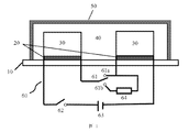
- FIG. 1 is a schematic diagram of the structure of a battery without a separator of Example 1.
- FIG. 1 is a schematic diagram of the structure of a battery without a separator of Example 1.
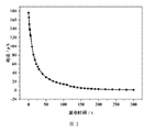
- FIG. 2 is a graph showing the correspondence between the short-circuit current and time of the separator-less battery of Example 1.
- FIG. 3 is a graph showing the correspondence between the open circuit voltage and time of the separator-less battery of Example 1.
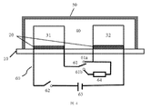
- FIG. 4 is a schematic structural diagram of a battery without a separator of Example 2.
- FIG. 4 is a schematic structural diagram of a battery without a separator of Example 2.
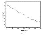
- FIG. 5 is a graph showing the relationship between the short-circuit current and time of the separator-less battery of Example 2.
- FIG. 6 is a graph showing the relationship between the open circuit voltage and time of the separator-less battery of Example 2.
- FIG. 1 is a schematic structural diagram of a battery without a separator in this embodiment.
- the battery of this embodiment is specifically a diffusion cell based on concentration difference, including an insulating substrate 10, two conductive metal layers 20, two metal oxide thin film layers 30 containing ions, an electrolyte 40, an encapsulant 50, and an external circuit 60.
- the two conductive metal layers 20 are respectively located on the surface of the insulating substrate 10 and are not in contact with each other. In this embodiment, the two conductive metal layers 20 are arranged side by side on the surface of the insulating substrate 10, and a gap of a certain distance is formed between the two.
- the insulating substrate may be a flexible insulating substrate or a rigid insulating substrate.
- the flexible insulating substrate may be silicone or plastic.
- the two metal oxide thin film layers 30 containing ions may use the same material or different materials, which are respectively located on the surfaces of the two conductive metal layers 20 without contacting each other.
- each ion-containing metal oxide thin film layer 30 covers the surface of one conductive metal layer 20, and the area of the ion-containing metal oxide thin film layer 30 does not exceed the area of the conductive metal layer 20, so that the two A gap of a certain distance is also formed between the metal oxide thin film layers 30 containing ions.
- the two ion-containing metal oxide thin film layers have a thickness of 180-220 nm, an area of 0.8-1.2 cm 2 , and a distance between the two of 0.8-1.2 cm.
- the material of the metal oxide thin film layer may be a composite of one or more of tungsten oxide, molybdenum oxide, niobium oxide, and nickel oxide.
- the ion may be hydrogen ion, lithium ion, sodium ion or potassium ion.
- the electrolyte 40 is wrapped around the two conductive metal layers 20 and the two ion-containing metal oxide thin film layers 30, and is filled between the two conductive metal layers 20 and the two ion-containing metals The gap between the oxide thin film layers 30.
- the electrolyte 40 is a liquid electrolyte or a gel electrolyte containing the same kinds of ions in the two metal oxide thin film layers 30 containing ions.
- the encapsulant 50 covers the periphery of the electrolyte 40.
- the encapsulant may be silica gel or plastic.
- the external circuit 60 is electrically connected to the two conductive metal layers 20.
- the external circuit 60 includes a charge-discharge switch 61, a power switch 62, a power supply 63, and an electrical appliance 64. Both ends of the charge-discharge switch 61 are electrically connected to the two conductive metal layers 20 through wires, respectively .
- the charge-discharge switch includes a charge 61a and a discharge 61b; when the charge-discharge switch 61 is located in the charge 61a and the power switch 62 is closed, the two conductive metal layers 20 and the power supply 63 are formed in series Charging circuit; when the charge-discharge switching switch 61 is located in the discharge gear 61b and the power switch 62 is turned off, the two conductive metal layers 20 and the electrical appliances 64 are connected in series to form a discharge circuit.
- the charge-discharge switching switch 61 is automatically turned off to keep electricity from leaking.
- the power switch 62 is used to charge the battery, and automatically disconnects when fully charged to prevent overcharging and protect the battery.
- the working process of the battery without a separator in this embodiment includes a charging process and a discharging process, as follows:
- (1) Charging process switch the charge-discharge switch 61 to the charging stage 61a, and at the same time close the power switch 62, thereby generating current in the two conductive metal layers 20, under the action of the current, the metal oxide film layer of the positive electrode
- the ions in the 30 and the electrolyte 40 migrate along the direction of the current to the inside of the metal oxide film layer 30 of the negative electrode until the metal oxide film layer 30 of the negative electrode can no longer contain ions.
- the charging and discharging switch 61 is automatically turned off Turn on, and then turn off the power switch 62.
- tungsten oxide containing lithium ions is used as the thin film layer, which has a thickness of 200 nm, and a liquid containing lithium ions at a certain concentration is used as an electrolyte to describe the charging and discharging process of the present invention in detail.
- the area of the film layer used in this embodiment is 1 cm 2 , and the distance between the two film layers is 1 cm.
- an injection voltage of 3V is preferred for 1 minute to inject lithium ions into the tungsten oxide film, and the color of the tungsten oxide film changes from transparent to In the colored state, the tungsten oxide film completes the step of implanting lithium ions.
- the charging current is 0.2A for 1min.
- the transmission rate of the negative film layer gradually decreases, and the transmission rate of the positive electrode film layer gradually increases until the transmission rate of the two film layers reaches a stable state. Change, the battery has been charged at this time, first turn off the charge and discharge switch, and then turn off the power switch.
- an ammeter is used to directly measure the short-circuit current and open-circuit voltage of the battery.
- FIG. 2 and FIG. 3 are the corresponding diagrams of the short-circuit current, open-circuit voltage, and time.
- the short-circuit current of the battery is up to 176 ⁇ A, and as the time increases, the short-circuit current gradually decreases, and the discharge ends after 300 seconds.
- the open circuit state the maximum measured open circuit voltage is 490mV. As the time increases, the open circuit voltage gradually decreases. After 300 seconds, the voltage drop is about 55mV.
- FIG. 4 is a schematic structural diagram of a battery without a separator in this embodiment.
- the battery in this embodiment is a flexible battery without a separator, which includes an insulating substrate 10, two conductive metal layers 20, a positive electrode film 31, a negative electrode film 32, an electrolyte 40, an encapsulant 50, and an external circuit 60.
- the two conductive metal layers 20 are respectively located on the surface of the insulating substrate 10 and are not in contact with each other.
- the insulating substrate 10 is a flexible insulating substrate, which may be silicone or plastic.
- the two conductive metal layers 20 are arranged side by side on the two sides of the surface of the flexible insulating substrate 10, and a gap of a certain distance is formed between the two.
- the positive electrode film 31 and the negative electrode film 32 are respectively located on the surfaces of the two conductive metal layers 20 and do not contact each other.
- the positive electrode film 31 and the negative electrode film 32 respectively cover the surface of one conductive metal layer 20, and the area of the positive electrode film 31 and the negative electrode film 32 does not exceed the area of the conductive metal layer 20, so that the positive electrode A gap of a certain distance is also formed between the film 31 and the negative electrode film 32.
- the thickness of the positive electrode film 31 and the negative electrode film 32 are both 180-220 nm, the area is 0.8-1.2 cm 2 , and the distance between the two is 0.8-1.2 cm.
- the positive electrode thin film 31 and the negative electrode thin film 32 are respectively two thin film materials that can be implanted with ions, and the ions may be hydrogen ions, lithium ions, sodium ions, or potassium ions.
- the electrolyte 40 is wrapped around the positive electrode film 31, the negative electrode film 32 and the two conductive metal layers 20, and is filled between the positive electrode film 31 and the negative electrode film 32 and the two conductive metal layers The gap between 20.
- the electrolyte 40 is a liquid electrolyte or a gel electrolyte containing the same kind of ions as in the positive electrode film 31 and the negative electrode film 32.
- the encapsulant 50 covers the periphery of the electrolyte 40.
- the encapsulant may be silica gel or plastic.
- the external circuit 60 is electrically connected to the two conductive metal layers 20.
- the external circuit 60 includes a charge-discharge switch 61, a power switch 62, a power supply 63, and an electrical appliance 64. Both ends of the charge-discharge switch 61 are electrically connected to the two conductive metal layers 20 through wires, respectively .
- the charge-discharge switch includes a charge 61a and a discharge 61b; when the charge-discharge switch 61 is located in the charge 61a and the power switch 62 is closed, the two conductive metal layers 20 and the power supply 63 are formed in series Charging circuit; when the charge-discharge switching switch 61 is located in the discharge gear 61b and the power switch 62 is turned off, the two conductive metal layers 20 and the electrical appliances 64 are connected in series to form a discharge circuit.
- the charge-discharge switching switch 61 is automatically turned off to keep electricity from leaking.
- the power switch 62 is used to charge the battery, and automatically disconnects when fully charged to prevent overcharging and protect the battery.
- the working process of the battery without a separator in this embodiment includes a charging process and a discharging process, as follows:
- Charging process switch the charge-discharge switch 61 to the charging stage 61a, and at the same time close the power switch 62, thereby generating current in the two conductive metal layers 20, under the effect of the current, the positive electrode film 31 and the electrolyte
- the ions in 40 migrate to the inside of the negative electrode film 32 along the direction of the current until the negative electrode film 32 can no longer contain ions.
- charging is completed, the charge and discharge switch 61 is automatically turned off, and then the power switch 62 is turned off.
- the thickness of the positive electrode film and the negative electrode film are both 200 nm, the area size is 1 cm 2 , and the distance between the two electrode films is 1 cm.
- an ammeter is used to directly measure the current and voltage changes during the discharge of the battery without a separator. Use an ammeter to short-circuit the battery for discharge, and check the battery voltage and current output at intervals. Please refer to FIG. 2 and FIG. 3, which are the corresponding diagrams of short-circuit current, open circuit voltage and time during discharge, respectively.
- the current is up to 80 ⁇ A, and as time increases, the short-circuit current gradually decreases, and the current drops to about 20 ⁇ A after 300 seconds; also during the discharge process, the measured open circuit voltage is up to 0.62V, with As the time increases, the open circuit voltage gradually decreases. After 50 seconds, the voltage drops to about 0.45V. In the subsequent 30 seconds, the battery voltage is in a stable state without change.
- the positive and negative electrodes of the battery of the present invention can use the same material or different materials.
- the charge and discharge process does not require an electric field and potential difference, but uses the difference in the concentration of ions between the positive and negative electrode layers.
- the diffusion movement is carried out to realize the continuous migration of ions between the positive and negative electrodes, so as to realize the charging and discharging effect of the battery.
- the positive and negative electrodes of the battery of the present invention can also use the same material with potential difference as the traditional battery.
- the present invention adopts a flat design in structure, which can be used in various bending situations without worrying about the positive battery during use.
- the short circuit caused by the contact of the negative electrode can remove the separator layer in the conventional battery, thereby achieving the flexibility of the battery.
- the invention has the characteristics of simple structure, low cost and high safety, and has good application prospects in the field of batteries.
Landscapes
- Engineering & Computer Science (AREA)
- Manufacturing & Machinery (AREA)
- Chemical & Material Sciences (AREA)
- Chemical Kinetics & Catalysis (AREA)
- Electrochemistry (AREA)
- General Chemical & Material Sciences (AREA)
- Secondary Cells (AREA)
- Battery Electrode And Active Subsutance (AREA)
Abstract
本发明涉及一种无隔膜的电池。所述无隔膜的电池包括绝缘基片、两个导电金属层、正电极层、负电极层、电解质、封装胶和外电路;所述两个导电金属层分别位于所述绝缘基片表面,且互不接触;所述正电极层和负电极层分别位于所述两个导电金属层表面,且互不接触;所述电解质包覆于所述正电极层、负电极层和两个导电金属层的周围,且填充于所述正电极层和负电极层之间以及两个导电金属层之间的空隙;所述封装胶包覆于所述电解质外围;所述外电路与所述两个导电金属层电连接。本发明具备结构简单、成本较低、安全性高的特点,在电池领域有良好的应用前景。
Description
本发明涉及电池领域,尤其涉及一种无隔膜的电池。
传统锂离子电池被称为“摇椅式电池”,主要由正极、负极、隔膜和电解质组成,正极材料是含锂的化合物,负极通常是一种层状结构的材料,电解质也是含锂的。充电过程中,正极材料浅层的锂离子在电场作用下,从晶格脱出,插入到负极的层间空隙中;放电过程中,负极中的锂离子自发的脱出,回到正极材料中。传统锂离子电池实现充放电,一要正负极材料之间必须存在电位差,二要有电场,此外,传统锂离子电池结构中要有隔膜,用以使电池的正负极分隔开来,防止两极接触而短路。
发明内容
基于此,本发明的目的在于,提供一种无隔膜的电池,可以实现无隔膜结构。
本发明的目的是通过以下技术方案实现的:一种无隔膜的电池,包括绝缘基片、两个导电金属层、正电极层、负电极层、电解质、封装胶和外电路;所述两个导电金属层分别位于所述绝缘基片表面,且互不接触;所述正电极层和负电极层分别位于所述两个导电金属层表面,且互不接触;所述电解质包覆于所述正电极层、负电极层和两个导电金属层的周围,且填充于所述正电极层和负电极层之间以及两个导电金属层之间的空隙;所述封装胶包覆于所述电解质外围;所述外电路与所述两个导电金属层电连接。
本发明的充放电原理是:充电时,在导电金属层中的电流驱动下,位于正电极层内部和电解质中的离子沿着电流方向迁移至负电极层内,直至负电极层无法再容纳离子,此时充电完毕;放电时,由于正负电极层中离子浓度存在差异,使得离子自发地从负电极层脱出扩散至电解质和正电极层内,直至正负电极层和电解质中的离子浓度相等,此时放电完毕。
相对于现有技术,本发明在结构上采用扁平化设计,正负电极之间互不接触,距离较大,无需担心电池在使用过程中正负电极触碰而引起的短路,从而可以去掉传统电池中的隔膜层,实现无隔膜结构。本发明具备结构简单、成本较低、安全性高的特点,在电池领域有良好的应用前景。
进一步地,所述正电极层、负电极层为同一种含有离子的金属氧化物薄膜层。
进一步地,所述含有离子的金属氧化物薄膜层中,所述金属氧化物薄膜层的材料为氧化 钨、氧化钼、氧化铌、氧化镍中的一种或多种的复合。
进一步地,所述含有离子的金属氧化物薄膜层中,所述离子为氢离子、锂离子、钠离子或钾离子。
进一步地,所述正电极层、负电极层为同一种材料。
进一步地,所述电解质为含有与所述含有离子的金属氧化物薄膜层中同种离子的液体电解质或凝胶体电解质。
进一步地,所述正电极层、负电极层分别为两种可以注入离子的薄膜层,两者之间存在电位差。
进一步地,所述离子为氢离子、锂离子、钠离子或钾离子。
进一步地,所述电解质为含有与所述可以注入离子的薄膜层中同种离子的液体电解质或凝胶体电解质。
进一步地,所述正电极层材料为钴酸锂或磷酸铁锂;所述负电极层材料为锂片、硅片、石墨烯或石墨片。
进一步地,所述外电路包括充放电切换开关、电源开关、电源和用电器,所述充放电切换开关包括充电档和放电档;当所述充放电切换开关位于充电档且所述电源开关闭合时,所述两个导电金属层与电源串联形成充电回路;当所述充放电切换开关位于放电档且所述电源开关断开时,所述两个导电金属层与用电器串联形成放电回路。
进一步地,所述正、负电极层的厚度均为180~220nm。
进一步地,所述正、负电极层的面积均为0.8~1.2cm
2。
进一步地,所述正、负电极层之间的距离为0.8~1.2cm。
进一步地,所述绝缘基片为柔性绝缘基片或刚性绝缘基片。
进一步地,所述柔性绝缘基片为硅胶或塑料。
进一步地,所述封装胶为硅胶或塑料。
为了更好地理解和实施,下面结合附图详细说明本发明。
图1为实施例1的无隔膜的电池的结构示意图。
图2为实施例1的无隔膜的电池的短路电流与时间的对应关系图。
图3为实施例1的无隔膜的电池的开路电压与时间的对应关系图。
图4为实施例2的无隔膜的电池的结构示意图。
图5为实施例2的无隔膜的电池的短路电流与时间的对应关系图。
图6为实施例2的无隔膜的电池的开路电压与时间的对应关系图。
为了使本发明的目的、技术方案及优点更加清楚明白,以下结合附图及实施例,对本发明进行进一步详细说明。应当理解,此处描述的具体实施例仅用以解释本发明,并不用于限定本发明。此外,下面所描述的本发明各个实施方式中所涉及到的技术特征只要彼此之间未构成冲突就可以相互组合。
实施例1
请参阅图1,其为本实施例的无隔膜的电池的结构示意图。本实施例的电池具体为一种基于浓度差的扩散电池,包括绝缘基片10、两个导电金属层20、两个含有离子的金属氧化物薄膜层30、电解质40、封装胶50和外电路60。
所述两个导电金属层20分别位于所述绝缘基片10表面,且互不接触。本实施例中,所述两个导电金属层20并排设于所述绝缘基片10表面的两侧,两者之间形成一定距离的空隙。所述绝缘基片可以为柔性绝缘基片或刚性绝缘基片。所述柔性绝缘基片可以为硅胶或塑料。
所述两个含有离子的金属氧化物薄膜层30可以采用同一种材料,也可以采用不同种材料,分别位于所述两个导电金属层20表面,且互不接触。本实施例中,每个含有离子的金属氧化物薄膜层30覆盖于一个导电金属层20表面,且含有离子的金属氧化物薄膜层30的面积不超过导电金属层20的面积,从而所述两个含有离子的金属氧化物薄膜层30之间也形成一定距离的空隙。优选的,所述两个含有离子的金属氧化物薄膜层的厚度均为180~220nm、面积均为0.8~1.2cm
2,两者之间的距离为0.8~1.2cm。所述金属氧化物薄膜层的材料可以为氧化钨、氧化钼、氧化铌、氧化镍中的一种或多种的复合。所述离子可以为氢离子、锂离子、钠离子或钾离子。
所述电解质40包覆于所述两个导电金属层20和两个含有离子的金属氧化物薄膜层30的周围,且填充于所述两个导电金属层20之间以及两个含有离子的金属氧化物薄膜层30之间的空隙。本实施例中,所述电解质40为含有与所述两个含有离子的金属氧化物薄膜层30中同种离子的液体电解质或凝胶体电解质。
所述封装胶50包覆于所述电解质40外围。本实施例中,所述封装胶可以为硅胶或塑料。
所述外电路60与所述两个导电金属层20电连接。本实施例中,所述外电路60包括充放电切换开关61、电源开关62、电源63和用电器64,所述充放电切换开关61的两端分别通过导线与两个导电金属层20电连接,所述充放电切换开关包括充电档61a和放电档61b;当所述充放电切换开关61位于充电档61a且所述电源开关62闭合时,所述两个导电金属层20 与电源63串联形成充电回路;当所述充放电切换开关61位于放电档61b且所述电源开关62断开时,所述两个导电金属层20与用电器64串联形成放电回路。此外,在充电时,当无电流流过所述充放电切换开关61时,所述充放电切换开关61自动断开,以保持电量不发生漏电。所述电源开关62用于电池充电,并在充满电时自动断开,防止过充,保护电池。
本实施例的无隔膜的电池的工作过程包括充电过程和放电过程,具体如下:
(1)充电过程:将充放电切换开关61切换至充电档61a,同时将电源开关62闭合,从而在两个导电金属层20中产生电流,在电流的作用下,正极的金属氧化物薄膜层30内部和电解质40中的离子沿着电流方向迁移至负极的金属氧化物薄膜层30内部,直至负极的金属氧化物薄膜层30无法再容纳离子,此时充电完毕,充放电切换开关61自动断开,然后再把电源开关62断开。
(2)放电过程:将充放电切换开关61切换至放电档61b,与用电器64电连接,由于正负极的金属氧化物薄膜层30中离子浓度存在差异,使得离子自发地从负极的金属氧化物薄膜层30脱出,扩散至电解质40和正极的金属氧化物薄膜层30内;与此同时,电子从外电路中迁移,产生电流供用电器64工作,直至正负极的金属氧化物薄膜层30与电解质40中的离子浓度相等,此时电池电量耗尽。
本实施例以含有锂离子的氧化钨作为薄膜层,其厚度为200nm,并使用含有一定浓度的锂离子的液体作为电解质,来详细描述本发明的充放电过程。本实施例所采用的薄膜层面积大小为1cm
2,两个薄膜层之间的距离为1cm。由于要实现离子的扩散效果,需要先为薄膜层注入一定浓度锂离子,本实施例优选3V的注入电压,持续1min,使锂离子注入氧化钨薄膜中,并且氧化钨薄膜颜色由透明态变为着色态,此时氧化钨薄膜完成注入锂离子步骤。
当给电池充电时,充电电流大小0.2A,持续1min,负极薄膜层的透过率逐渐减小,而正极薄膜层透过率逐渐增加,直至两个薄膜层透过率达到稳定状态,不再变化,此时电池已经充电完毕,先断开充放电切换开关,再断开电源开关。
本实施例中,为了直观了解本发明的技术效果,采用了电流表直接测量电池的短路电流与开路电压,请参阅图2和图3,其分别为短路电流、开路电压与时间的对应关系图。在短路状态下,电池的短路电流最高为176μA,且随着时间增加,短路电流逐渐减少,在300秒后放电结束。而在开路状态下,测得开路电压最高为490mV,随着时间增加,开路电压逐渐降低,在300秒后电压降为55mV左右。上述测试结果充分证明了本实施例从原理上、技术上均能实现作为能源电池的基本功能与技术效果,在新能源领域拥有广泛的应用前景。
实施例2
请参阅图4,其为本实施例的无隔膜的电池的结构示意图。本实施例的电池具体为一种无隔膜的柔性电池,包括绝缘基片10、两个导电金属层20、正电极薄膜31、负电极薄膜32、电解质40、封装胶50和外电路60。
所述两个导电金属层20分别位于所述绝缘基片10表面,且互不接触。本实施例中,所述绝缘基片10为柔性绝缘基片,可以是硅胶或塑料。所述两个导电金属层20并排设于所述柔性绝缘基片10表面的两侧,两者之间形成一定距离的空隙。
所述正电极薄膜31和负电极薄膜32之间存在电位差,其分别位于所述两个导电金属层20表面,且互不接触。本实施例中,正电极薄膜31和负电极薄膜32分别覆盖于一个导电金属层20表面,且正电极薄膜31和负电极薄膜32的面积不超过导电金属层20的面积,从而所述正电极薄膜31和负电极薄膜32之间也形成一定距离的空隙。优选的,所述正电极薄膜31和负电极薄膜32的厚度均为180~220nm、面积均为0.8~1.2cm
2,两者之间的距离为0.8~1.2cm。所述正电极薄膜31和负电极薄膜32分别为两种可以注入离子的薄膜材料,所述离子可以为氢离子、锂离子、钠离子或钾离子。
所述电解质40包覆于所述正电极薄膜31、负电极薄膜32和两个导电金属层20的周围,且填充于所述正电极薄膜31和负电极薄膜32之间以及两个导电金属层20之间的空隙。本实施例中,所述电解质40为含有与所述正电极薄膜31和负电极薄膜32中同种离子的液体电解质或凝胶体电解质。
所述封装胶50包覆于所述电解质40外围。本实施例中,所述封装胶可以为硅胶或塑料。
所述外电路60与所述两个导电金属层20电连接。本实施例中,所述外电路60包括充放电切换开关61、电源开关62、电源63和用电器64,所述充放电切换开关61的两端分别通过导线与两个导电金属层20电连接,所述充放电切换开关包括充电档61a和放电档61b;当所述充放电切换开关61位于充电档61a且所述电源开关62闭合时,所述两个导电金属层20与电源63串联形成充电回路;当所述充放电切换开关61位于放电档61b且所述电源开关62断开时,所述两个导电金属层20与用电器64串联形成放电回路。此外,在充电时,当无电流流过所述充放电切换开关61时,所述充放电切换开关61自动断开,以保持电量不发生漏电。所述电源开关62用于电池充电,并在充满电时自动断开,防止过充,保护电池。
本实施例的无隔膜的电池的工作过程包括充电过程和放电过程,具体如下:
(1)充电过程:将充放电切换开关61切换至充电档61a,同时将电源开关62闭合,从而在两个导电金属层20中产生电流,在电流的作用下,正电极薄膜31内部和电解质40中的离子沿着电流方向迁移至负电极薄膜32内部,直至负电极薄膜32无法再容纳离子,此时充电完毕,充放电切换开关61自动断开,然后再把电源开关62断开。
(2)放电过程:将充放电切换开关61切换至放电档61b,与用电器64电连接,由于正电极薄膜31和负电极薄膜32存在浓度差和电位差,使得离子自发地从负电极薄膜32脱出,扩散至电解质40和正电极薄膜31内;与此同时,电子从外电路中迁移,产生电流供用电器64工作,直至正电极薄膜31、负电极薄膜32与电解质40中的离子浓度相等,此时电池电量耗尽。
本实施例中,正电极薄膜和负电极薄膜的厚度均为200nm,面积大小为1cm
2,两个电极薄膜之间的距离为1cm。为了直观了解本发明的技术效果,采用了电流表直接测量无隔膜的电池的放电过程中的电流与电压变化。使用电流表短接电池进行放电,并每隔一段时间检测电池的电压和电流输出大小。请参阅图2和图3,其分别为放电过程中的短路电流、开路电压与时间的对应关系图。在整个放电过程中,电流最高为80μA,且随着时间增加,短路电流逐渐减少,在300秒后电流降为20μA左右;同样在放电过程中,所测得开路电压最高为0.62V,随着时间增加,开路电压逐渐降低,50秒后电压降为0.45V左右,在后续的30秒内,电池电压处于稳定状态,没有发生变化。上述测试结果充分证明了本实施例从原理上、技术上均能实现作为能源电池的基本功能与技术效果,在新能源领域拥有广泛的应用前景。
相对于现有技术,本发明的电池正负极可以采用同一种材料,也可以采用不同种材料,充放电过程无需存在电场和电位差,而是利用离子在正负极层之间的浓度差异进行扩散运动,实现离子不断在正负极之间来回迁移,从而实现电池的充放电效果。本发明的电池正负极也可以采用跟传统电池一样的具有电位差的材料,同时,本发明在结构上采用扁平化设计,可以在各种弯折的情况下,无需担心电池在使用过程中正负极触碰而引起的短路,从而可以去掉传统电池中的隔膜层,进而实现电池柔性化。本发明具备结构简单、成本较低、安全性高的特点,在电池领域有良好的应用前景。
以上所述实施例仅表达了本发明的几种实施方式,其描述较为具体和详细,但并不能因此而理解为对发明专利范围的限制。应当指出的是,对于本领域的普通技术人员来说,在不脱离本发明构思的前提下,还可以做出若干变形和改进,这些都属于本发明的保护范围。
Claims (17)
- 一种无隔膜的电池,其特征在于,包括绝缘基片、两个导电金属层、正电极层、负电极层、电解质、封装胶和外电路;所述两个导电金属层分别位于所述绝缘基片表面,且互不接触;所述正电极层和负电极层分别位于所述两个导电金属层表面,且互不接触;所述电解质包覆于所述正电极层、负电极层和两个导电金属层的周围,且填充于所述正电极层和负电极层之间以及两个导电金属层之间的空隙;所述封装胶包覆于所述电解质外围;所述外电路与所述两个导电金属层电连接。
- 根据权利要求1所述的无隔膜的电池,其特征在于,所述正电极层、负电极层均为含有离子的金属氧化物薄膜层。
- 根据权利要求2所述的无隔膜的电池,其特征在于,所述含有离子的金属氧化物薄膜层中,所述金属氧化物薄膜层的材料为氧化钨、氧化钼、氧化铌、氧化镍中的一种或多种的复合。
- 根据权利要求3所述的无隔膜的电池,其特征在于,所述含有离子的金属氧化物薄膜层中,所述离子为氢离子、锂离子、钠离子或钾离子。
- 根据权利要求2所述的无隔膜的电池,其特征在于,所述正电极层、负电极层为同一种材料。
- 根据权利要求4所述的无隔膜的电池,其特征在于,所述电解质为含有与所述含有离子的金属氧化物薄膜层中同种离子的液体电解质或凝胶体电解质。
- 根据权利要求1所述的无隔膜的电池,其特征在于,所述正电极层、负电极层分别为两种可以注入离子的薄膜层,两者之间存在电位差。
- 根据权利要求7所述的无隔膜的电池,其特征在于,所述离子为氢离子、锂离子、钠离子或钾离子。
- 根据权利要求8所述的无隔膜的电池,其特征在于,所述电解质为含有与所述可以注入离子的薄膜层中同种离子的液体电解质或凝胶体电解质。
- 根据权利要求7所述的无隔膜的电池,其特征在于,所述正电极层材料为钴酸锂或磷酸铁锂;所述负电极层材料为锂片、硅片、石墨烯或石墨片。
- 根据权利要求1所述的无隔膜的电池,其特征在于,所述外电路包括充放电切换开关、电源开关、电源和用电器,所述充放电切换开关包括充电档和放电档;当所述充放电切换开关位于充电档且所述电源开关闭合时,所述两个导电金属层与电源串联形成充电回路;当所述充放电切换开关位于放电档且所述电源开关断开时,所述两个导电金属层与用电器串 联形成放电回路。
- 根据权利要求1所述的无隔膜的电池,其特征在于,所述正、负电极层的厚度均为180~220nm。
- 根据权利要求12所述的无隔膜的电池,其特征在于,所述正、负电极层的面积均为0.8~1.2cm 2。
- 根据权利要求13所述的无隔膜的电池,其特征在于,所述正、负电极层之间的距离为0.8~1.2cm。
- 根据权利要求1所述的无隔膜的电池,其特征在于,所述绝缘基片为柔性绝缘基片或刚性绝缘基片。
- 根据权利要求15所述的无隔膜的电池,其特征在于,所述柔性绝缘基片为硅胶或塑料。
- 根据权利要求1所述的无隔膜的电池,其特征在于,所述封装胶为硅胶或塑料。
Priority Applications (1)
| Application Number | Priority Date | Filing Date | Title |
|---|---|---|---|
| PCT/CN2018/111163 WO2020082205A1 (zh) | 2018-10-22 | 2018-10-22 | 一种无隔膜的电池 |
Applications Claiming Priority (1)
| Application Number | Priority Date | Filing Date | Title |
|---|---|---|---|
| PCT/CN2018/111163 WO2020082205A1 (zh) | 2018-10-22 | 2018-10-22 | 一种无隔膜的电池 |
Publications (1)
| Publication Number | Publication Date |
|---|---|
| WO2020082205A1 true WO2020082205A1 (zh) | 2020-04-30 |
Family
ID=70330851
Family Applications (1)
| Application Number | Title | Priority Date | Filing Date |
|---|---|---|---|
| PCT/CN2018/111163 Ceased WO2020082205A1 (zh) | 2018-10-22 | 2018-10-22 | 一种无隔膜的电池 |
Country Status (1)
| Country | Link |
|---|---|
| WO (1) | WO2020082205A1 (zh) |
Citations (3)
| Publication number | Priority date | Publication date | Assignee | Title |
|---|---|---|---|---|
| CN2930747Y (zh) * | 2005-12-28 | 2007-08-08 | 区都 | 电离子药贴 |
| CN103503273A (zh) * | 2011-06-30 | 2014-01-08 | 松下电器产业株式会社 | 电池充电器以及电源装置 |
| CN106910940A (zh) * | 2017-04-11 | 2017-06-30 | 中国科学院合肥物质科学研究院 | 一种无隔膜的超级电容器/锂电池 |
-
2018
- 2018-10-22 WO PCT/CN2018/111163 patent/WO2020082205A1/zh not_active Ceased
Patent Citations (3)
| Publication number | Priority date | Publication date | Assignee | Title |
|---|---|---|---|---|
| CN2930747Y (zh) * | 2005-12-28 | 2007-08-08 | 区都 | 电离子药贴 |
| CN103503273A (zh) * | 2011-06-30 | 2014-01-08 | 松下电器产业株式会社 | 电池充电器以及电源装置 |
| CN106910940A (zh) * | 2017-04-11 | 2017-06-30 | 中国科学院合肥物质科学研究院 | 一种无隔膜的超级电容器/锂电池 |
Similar Documents
| Publication | Publication Date | Title |
|---|---|---|
| Han et al. | Durable, flexible self-standing hydrogel electrolytes enabling high-safety rechargeable solid-state zinc metal batteries | |
| JP6979731B2 (ja) | 全固体リチウム電池及びその製造方法 | |
| JP3198828B2 (ja) | 全固体リチウム二次電池の製造法 | |
| CN108598371A (zh) | 一种柔性固态锂离子电池用复合负极片及其制备方法以及在固态锂离子电池中的应用 | |
| CN103247823B (zh) | 全固态锂离子电池及其制备方法 | |
| CN104733783A (zh) | 一种锂离子电池的制备方法 | |
| WO2023024404A1 (zh) | 一种锂离子电池预锂化方法及锂离子电池 | |
| CN203536529U (zh) | 一种锂离子电池 | |
| CN109818085A (zh) | 一种铅硅复合双极性电池 | |
| CN107394285A (zh) | 金属离子电池 | |
| CN116598622A (zh) | 一种提升锂电池容量的化成方法 | |
| CN109286045B (zh) | 一种锂离子电池及其制作方法和用途 | |
| WO2015096523A1 (zh) | 电池装置及电子设备 | |
| CN109411834B (zh) | 一种基于浓度差的扩散电池 | |
| WO2020082205A1 (zh) | 一种无隔膜的电池 | |
| JPS63298980A (ja) | 固体電解質電池 | |
| CN109449505A (zh) | 一种无隔膜的柔性电池 | |
| JPS5894770A (ja) | 無漏液密閉形鉛蓄電池 | |
| CN201918465U (zh) | 聚合物锂离子电池 | |
| CN207883808U (zh) | 一种高倍率锂离子电池 | |
| CN207504127U (zh) | 一种三端子电场效应型铅酸蓄电池 | |
| CN106290504A (zh) | 锑铅阳极氧化复合参比电极及其制备方法和应用 | |
| CN204118141U (zh) | 电池盖板 | |
| RU2794514C1 (ru) | Радиоизотопный твердотельный самозаряжающийся конденсатор | |
| RU134695U1 (ru) | Устройство для накопления и хранения электрической энергии (варианты) |
Legal Events
| Date | Code | Title | Description |
|---|---|---|---|
| 121 | Ep: the epo has been informed by wipo that ep was designated in this application |
Ref document number: 18938184 Country of ref document: EP Kind code of ref document: A1 |
|
| NENP | Non-entry into the national phase |
Ref country code: DE |
|
| 122 | Ep: pct application non-entry in european phase |
Ref document number: 18938184 Country of ref document: EP Kind code of ref document: A1 |