WO2020080176A1 - Secondary battery management system, secondary battery management method and secondary battery management program of said secondary battery management system, and secondary battery system - Google Patents
Secondary battery management system, secondary battery management method and secondary battery management program of said secondary battery management system, and secondary battery system Download PDFInfo
- Publication number
- WO2020080176A1 WO2020080176A1 PCT/JP2019/039585 JP2019039585W WO2020080176A1 WO 2020080176 A1 WO2020080176 A1 WO 2020080176A1 JP 2019039585 W JP2019039585 W JP 2019039585W WO 2020080176 A1 WO2020080176 A1 WO 2020080176A1
- Authority
- WO
- WIPO (PCT)
- Prior art keywords
- secondary battery
- charging rate
- charging
- rate
- constant current
- Prior art date
Links
Images


Classifications
-
- H—ELECTRICITY
- H02—GENERATION; CONVERSION OR DISTRIBUTION OF ELECTRIC POWER
- H02J—CIRCUIT ARRANGEMENTS OR SYSTEMS FOR SUPPLYING OR DISTRIBUTING ELECTRIC POWER; SYSTEMS FOR STORING ELECTRIC ENERGY
- H02J7/00—Circuit arrangements for charging or depolarising batteries or for supplying loads from batteries
- H02J7/007—Regulation of charging or discharging current or voltage
- H02J7/00712—Regulation of charging or discharging current or voltage the cycle being controlled or terminated in response to electric parameters
-
- G—PHYSICS
- G01—MEASURING; TESTING
- G01R—MEASURING ELECTRIC VARIABLES; MEASURING MAGNETIC VARIABLES
- G01R31/00—Arrangements for testing electric properties; Arrangements for locating electric faults; Arrangements for electrical testing characterised by what is being tested not provided for elsewhere
- G01R31/36—Arrangements for testing, measuring or monitoring the electrical condition of accumulators or electric batteries, e.g. capacity or state of charge [SoC]
- G01R31/382—Arrangements for monitoring battery or accumulator variables, e.g. SoC
- G01R31/3835—Arrangements for monitoring battery or accumulator variables, e.g. SoC involving only voltage measurements
-
- G—PHYSICS
- G01—MEASURING; TESTING
- G01R—MEASURING ELECTRIC VARIABLES; MEASURING MAGNETIC VARIABLES
- G01R31/00—Arrangements for testing electric properties; Arrangements for locating electric faults; Arrangements for electrical testing characterised by what is being tested not provided for elsewhere
- G01R31/36—Arrangements for testing, measuring or monitoring the electrical condition of accumulators or electric batteries, e.g. capacity or state of charge [SoC]
- G01R31/392—Determining battery ageing or deterioration, e.g. state of health
-
- H—ELECTRICITY
- H01—ELECTRIC ELEMENTS
- H01M—PROCESSES OR MEANS, e.g. BATTERIES, FOR THE DIRECT CONVERSION OF CHEMICAL ENERGY INTO ELECTRICAL ENERGY
- H01M10/00—Secondary cells; Manufacture thereof
- H01M10/42—Methods or arrangements for servicing or maintenance of secondary cells or secondary half-cells
- H01M10/425—Structural combination with electronic components, e.g. electronic circuits integrated to the outside of the casing
-
- H—ELECTRICITY
- H01—ELECTRIC ELEMENTS
- H01M—PROCESSES OR MEANS, e.g. BATTERIES, FOR THE DIRECT CONVERSION OF CHEMICAL ENERGY INTO ELECTRICAL ENERGY
- H01M10/00—Secondary cells; Manufacture thereof
- H01M10/42—Methods or arrangements for servicing or maintenance of secondary cells or secondary half-cells
- H01M10/44—Methods for charging or discharging
- H01M10/441—Methods for charging or discharging for several batteries or cells simultaneously or sequentially
-
- H—ELECTRICITY
- H01—ELECTRIC ELEMENTS
- H01M—PROCESSES OR MEANS, e.g. BATTERIES, FOR THE DIRECT CONVERSION OF CHEMICAL ENERGY INTO ELECTRICAL ENERGY
- H01M10/00—Secondary cells; Manufacture thereof
- H01M10/42—Methods or arrangements for servicing or maintenance of secondary cells or secondary half-cells
- H01M10/46—Accumulators structurally combined with charging apparatus
-
- H—ELECTRICITY
- H01—ELECTRIC ELEMENTS
- H01M—PROCESSES OR MEANS, e.g. BATTERIES, FOR THE DIRECT CONVERSION OF CHEMICAL ENERGY INTO ELECTRICAL ENERGY
- H01M10/00—Secondary cells; Manufacture thereof
- H01M10/42—Methods or arrangements for servicing or maintenance of secondary cells or secondary half-cells
- H01M10/48—Accumulators combined with arrangements for measuring, testing or indicating the condition of cells, e.g. the level or density of the electrolyte
- H01M10/482—Accumulators combined with arrangements for measuring, testing or indicating the condition of cells, e.g. the level or density of the electrolyte for several batteries or cells simultaneously or sequentially
-
- H—ELECTRICITY
- H02—GENERATION; CONVERSION OR DISTRIBUTION OF ELECTRIC POWER
- H02J—CIRCUIT ARRANGEMENTS OR SYSTEMS FOR SUPPLYING OR DISTRIBUTING ELECTRIC POWER; SYSTEMS FOR STORING ELECTRIC ENERGY
- H02J7/00—Circuit arrangements for charging or depolarising batteries or for supplying loads from batteries
- H02J7/0029—Circuit arrangements for charging or depolarising batteries or for supplying loads from batteries with safety or protection devices or circuits
- H02J7/00302—Overcharge protection
-
- H—ELECTRICITY
- H02—GENERATION; CONVERSION OR DISTRIBUTION OF ELECTRIC POWER
- H02J—CIRCUIT ARRANGEMENTS OR SYSTEMS FOR SUPPLYING OR DISTRIBUTING ELECTRIC POWER; SYSTEMS FOR STORING ELECTRIC ENERGY
- H02J7/00—Circuit arrangements for charging or depolarising batteries or for supplying loads from batteries
- H02J7/0047—Circuit arrangements for charging or depolarising batteries or for supplying loads from batteries with monitoring or indicating devices or circuits
- H02J7/0048—Detection of remaining charge capacity or state of charge [SOC]
-
- H—ELECTRICITY
- H02—GENERATION; CONVERSION OR DISTRIBUTION OF ELECTRIC POWER
- H02J—CIRCUIT ARRANGEMENTS OR SYSTEMS FOR SUPPLYING OR DISTRIBUTING ELECTRIC POWER; SYSTEMS FOR STORING ELECTRIC ENERGY
- H02J7/00—Circuit arrangements for charging or depolarising batteries or for supplying loads from batteries
- H02J7/0047—Circuit arrangements for charging or depolarising batteries or for supplying loads from batteries with monitoring or indicating devices or circuits
- H02J7/005—Detection of state of health [SOH]
-
- H—ELECTRICITY
- H02—GENERATION; CONVERSION OR DISTRIBUTION OF ELECTRIC POWER
- H02J—CIRCUIT ARRANGEMENTS OR SYSTEMS FOR SUPPLYING OR DISTRIBUTING ELECTRIC POWER; SYSTEMS FOR STORING ELECTRIC ENERGY
- H02J7/00—Circuit arrangements for charging or depolarising batteries or for supplying loads from batteries
- H02J7/007—Regulation of charging or discharging current or voltage
- H02J7/007188—Regulation of charging or discharging current or voltage the charge cycle being controlled or terminated in response to non-electric parameters
-
- H—ELECTRICITY
- H01—ELECTRIC ELEMENTS
- H01M—PROCESSES OR MEANS, e.g. BATTERIES, FOR THE DIRECT CONVERSION OF CHEMICAL ENERGY INTO ELECTRICAL ENERGY
- H01M10/00—Secondary cells; Manufacture thereof
- H01M10/42—Methods or arrangements for servicing or maintenance of secondary cells or secondary half-cells
- H01M10/425—Structural combination with electronic components, e.g. electronic circuits integrated to the outside of the casing
- H01M2010/4271—Battery management systems including electronic circuits, e.g. control of current or voltage to keep battery in healthy state, cell balancing
-
- Y—GENERAL TAGGING OF NEW TECHNOLOGICAL DEVELOPMENTS; GENERAL TAGGING OF CROSS-SECTIONAL TECHNOLOGIES SPANNING OVER SEVERAL SECTIONS OF THE IPC; TECHNICAL SUBJECTS COVERED BY FORMER USPC CROSS-REFERENCE ART COLLECTIONS [XRACs] AND DIGESTS
- Y02—TECHNOLOGIES OR APPLICATIONS FOR MITIGATION OR ADAPTATION AGAINST CLIMATE CHANGE
- Y02E—REDUCTION OF GREENHOUSE GAS [GHG] EMISSIONS, RELATED TO ENERGY GENERATION, TRANSMISSION OR DISTRIBUTION
- Y02E60/00—Enabling technologies; Technologies with a potential or indirect contribution to GHG emissions mitigation
- Y02E60/10—Energy storage using batteries
Definitions
- the present disclosure relates to a secondary battery management system, a secondary battery management method therefor, a secondary battery management program, and a secondary battery system.
- Some electric power systems that are linked to thermal power plants are equipped with secondary batteries to stabilize the grid. Charge / discharge control is performed on the secondary battery so that the secondary battery is within an operating range (SOC upper limit value and SOC lower limit value), for example.
- Patent Document 1 discloses estimating SOH (State of Health) and setting SOC within the upper limit value and the lower limit value by SOH.
- Rechargeable batteries are often placed in a standby state with a high charging rate so that they can be discharged with a margin when necessary.
- the secondary battery tends to deteriorate more easily if it is maintained for a long period of time in a state where the charging rate is high, and it is not preferable to maintain the state where the charging rate is higher than necessary.
- the present disclosure has been made in view of such circumstances, and a secondary battery management system capable of accurately setting a target charging rate of a secondary battery accurately by considering the degree of deterioration, and the same
- a secondary battery management method, a secondary battery management program, and a secondary battery system are provided.
- a first aspect of the present disclosure is a setting unit that sets a temporary target charging rate of a secondary battery based on a target power amount, and a charging rate of the secondary battery that has changed during a predetermined constant current charging period of the secondary battery. Based on the amount of change of the, the estimation unit that estimates the deterioration degree of the secondary battery, and the calculation unit that corrects the temporary target charging rate by the deterioration degree, and calculates the target charging rate of the secondary battery. It is a secondary battery management system provided.
- the deterioration degree of the secondary battery in the current state can be estimated each time based on the amount of change in the charging rate of the secondary battery during the constant current charging period performed during the charging period. Therefore, it is possible to more accurately estimate the degree of deterioration of the secondary battery. Then, in order to determine the target charging rate of the secondary battery by correcting the temporary target charging rate set on the basis of the target power amount with the deterioration degree, the charging capacity shortage due to deterioration is taken into consideration, and It becomes possible to store electricity in the secondary battery more reliably.
- the target charging rate of the secondary battery can be set appropriately in consideration of the degree of deterioration in the current state, it prevents the charging rate of the secondary battery from being maintained in an unnecessarily high state and shortens the battery life. Can be suppressed.
- the estimation unit is a charging rate change rate that is a change rate of a charging rate that has changed in the constant current charging period of the secondary battery in a current state, and the secondary battery in an initial state.
- the degree of deterioration of the secondary battery may be estimated based on the ratio to the change rate of the initial charging rate that has changed during the constant current charging period.
- the deterioration degree is estimated by the ratio of the charging rate change rate in the current state and the initial charging rate change rate in the secondary battery, the deterioration degree can be easily estimated.
- the rate of change of the initial charging rate of the secondary battery is the secondary battery that has changed during the predetermined constant current charging period that has been confirmed when the secondary battery is in the initial state (state before deterioration, for example, during trial run adjustment). This is the amount of change in the charging rate of the battery.
- the constant current charging period is set such that a measurement error is less than a preset upper limit value based on a sampling cycle relating to measurement of a charging rate in the secondary battery. Good.
- the constant current charging period by setting the constant current charging period based on the sampling cycle, it is possible to set the constant current charging period such that the measurement error is less than the preset upper limit value. It is possible to more accurately estimate the degree of deterioration of the battery. If the constant current charging period for estimating the deterioration degree is too short with respect to the sampling cycle for measuring the charging rate, the measurement error may increase.
- the calculation unit may issue a warning notification when the target charging rate is not within the preset charging rate allowable range.
- the secondary battery management system may include a charge control unit that starts constant current charging of the secondary battery when the charging rate of the secondary battery reaches a reference charging rate.
- the constant current charging is started when the charging rate reaches the reference charging rate, so that the charging rates of the secondary batteries for starting the constant current charging can be unified. That is, the state of the secondary battery in the constant current charging period for estimating the deterioration degree can be optimized so as to be performed under the same condition, and the deterioration degree can be estimated more accurately.
- a second aspect of the present disclosure is a secondary battery system that includes a secondary battery, a charging / discharging device that controls the amount of charging / discharging current flowing through the secondary battery, and the above-described secondary battery management system.
- a third aspect of the present disclosure is a setting step of setting a temporary target charging rate of a secondary battery based on a target power amount, and a charging rate of the secondary battery that has changed in a predetermined constant current charging period of the secondary battery. Based on the amount of change of the, the estimation step of estimating the deterioration degree of the secondary battery, and the calculation step of correcting the temporary target charging rate by the deterioration degree, and calculating the target charging rate of the secondary battery, It is a secondary battery management method that the user has.
- a fourth aspect of the present disclosure is a setting process of setting a temporary target charging rate of a secondary battery based on a target power amount, and a charging rate of the secondary battery that has changed in a predetermined constant current charging period of the secondary battery. Based on the amount of change of the, the estimation process of estimating the deterioration degree of the secondary battery, the calculation process of correcting the temporary target charging rate by the deterioration degree, and calculating the target charging rate of the secondary battery, It is a secondary battery management program to be executed by a computer.
- the target charging rate of the secondary battery can be appropriately set in consideration of the degree of deterioration.
- FIG. 1 is a diagram showing a schematic configuration of a secondary battery system according to an embodiment of the present disclosure.
- FIG. 3 is a functional block diagram showing functions included in a secondary battery management system according to an embodiment of the present disclosure.
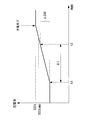
- FIG. 4 is a diagram showing a time course of a state of charge of a secondary battery in a secondary battery management system according to an embodiment of the present disclosure.
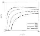
- FIG. 5 is a diagram showing a relationship between the efficiency of the charging / discharging device and the charging rate of the secondary battery in the secondary battery management system according to the embodiment of the present disclosure.
- 6 is a graph illustrating a relationship between a constant current charging period and an error in the secondary battery management system according to the embodiment of the present disclosure.
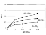
- FIG. 8 is a diagram showing a flowchart of a target charging rate calculation process by the secondary battery management system according to the embodiment of the present disclosure. It is a figure which illustrated the relationship between the deterioration ratio of a secondary battery, and a maintenance period.
- FIG. 1 is a diagram showing a schematic configuration of a secondary battery system 1 including a secondary battery management system 4 according to an embodiment of the present disclosure.
- the secondary battery system 1 according to the present embodiment includes a secondary battery 2, a charging / discharging device 3, and a secondary battery management system 4 as main components.
- the system 1 is connected to a power system 5 and a power consumption facility 6.
- the secondary battery 2 is a device capable of storing and discharging electric power.
- the secondary battery 2 is configured by combining a plurality of unit secondary batteries so as to have a desired voltage and capacity.
- the secondary battery 2 may be composed of one unit secondary battery.
- the secondary battery 2 is configured by using, for example, a lithium ion secondary battery, a lead secondary battery, a nickel hydrogen secondary battery, NaS (sodium sulfur battery) or the like.
- the charging / discharging device 3 controls the amount of charging / discharging current flowing through the secondary battery 2. Specifically, the charging / discharging device 3 charges the secondary battery 2 so that the charging rate of the secondary battery 2 approaches a target charging rate of the secondary battery 2 set in a secondary battery management system 4 described later. Performs discharge control. It is assumed that the charging / discharging device 3 is connected to a voltmeter that measures the open-end voltage of the secondary battery 2.
- the charging / discharging device 3 is connected to the electric power system 5 and the secondary battery 2 and distributes electric power.
- the power system 5 is, for example, a power transmission and distribution network that connects a power generation facility and a customer, and three-phase AC power is distributed. For this reason, when charging the secondary battery 2, the charging / discharging device 3 converts the three-phase alternating current into the direct current so that the electric power is circulated from the power system 5 to the secondary battery 2. When discharging the secondary battery 2, the charging / discharging device 3 converts the direct current into the three-phase alternating current to flow the power from the secondary battery 2 to the power consumption facility 6 or the power system 5.
- the state of charge (SOC) of the secondary battery 2 is the ratio of the remaining capacity (the amount of electric power charged in the secondary battery 2) to the fully charged state. Therefore, for example, when the remaining capacity is 0, the charging rate is 0%, and when the remaining capacity is in the fully charged state, the charging rate is 100%.
- the charging rate of the secondary battery 2 has a correlation with the open end voltage of the secondary battery 2 (the output voltage in the OCV open state (the output current is zero)), and is expressed as, for example, an SOC-OCV characteristic. There is something. Therefore, the current charging rate of the secondary battery 2 is estimated from the current open-ended voltage of the secondary battery 2 by acquiring the correlation such as the SOC-OCV characteristic as the characteristic of the secondary battery 2 in advance. can do.
- the charging / discharging device 3 charges the secondary battery 2 so that the open end voltage of the secondary battery 2 becomes the open end voltage corresponding to the target charging rate (SOCtemp and SOCt described later). If the charging rate of the secondary battery 2 can be estimated, it can be applied not only to the open circuit voltage.
- the charging / discharging device 3 charges the secondary battery 2 when a command to charge the secondary battery 2 to the target charging rate is input from the secondary battery management system 4, but the constant current charging is performed for at least a part of the time. Carry out.
- the constant current charging described here is a charging method for charging the secondary battery 2 by supplying a predetermined constant current value set in advance.
- the secondary battery management system 4 controls charging / discharging of the secondary battery 2. Specifically, the secondary battery management system 4 controls the charging / discharging of the secondary battery 2 by controlling the charging / discharging device 3, and manages the charge state of the secondary battery 2. In particular, the secondary battery management system 4 in the present embodiment sets the target charging rate of the secondary battery 2 in consideration of the degree of deterioration of the secondary battery 2.
- the secondary battery 2 has a lower chargeable capacity as the deterioration progresses. Therefore, the charged amount when the deteriorated secondary battery 2 is charged to a certain charging rate (SOC temp described later) is the charged amount when the deteriorated secondary battery 2 is charged to the charged rate. Will be smaller than. Therefore, if the influence of deterioration is not taken into consideration, the amount of electricity stored in the secondary battery 2 will decrease, and there is a possibility that the amount of electricity required for discharging cannot be stored. Therefore, in the secondary battery management system 4, by setting the target charging rate in consideration of the degree of deterioration of the secondary battery 2, the required amount of electricity can be more surely obtained without being insufficient or excessive. To store electricity.
- the secondary battery management system 4 includes, for example, a CPU (central processing unit), a memory such as a RAM (Random Access Memory), and a computer-readable recording medium, which are not shown.
- a CPU central processing unit
- a memory such as a RAM (Random Access Memory)
- a computer-readable recording medium which are not shown.
- a series of processes for realizing various functions described below are recorded in a recording medium or the like in the form of a program, and the CPU reads the program into the RAM or the like to execute information processing / arithmetic processing. With this, various functions described below are realized.
- the program may be installed in a ROM or other storage medium in advance, provided in a state where it is stored in a computer-readable storage medium, or delivered via wired or wireless communication means. May be applied.
- the computer-readable storage medium is a magnetic disk, a magneto-optical disk, a CD-ROM, a DVD-ROM, a semiconductor memory, or the like.
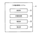
- FIG. 2 is a functional block diagram showing the functions of the secondary battery management system 4.
- the secondary battery management system 4 includes a setting unit 21, a charging control unit 22, an estimating unit 23, and a calculating unit 24.
- the setting unit 21 sets a temporary target charging rate (SOC temp described later) of the secondary battery 2 based on the target electric energy supplied from the secondary battery system 1.
- the target amount of electric power is the amount of electric power required in the discharging period until the next charging. That is, the target amount of power is stored in the secondary battery 2 in consideration of the efficiency of the charging / discharging device 3, so that the target battery can be taken out of the secondary battery 2 as a discharge when needed during the discharging period until the next charging. Used for power demand.
- the target amount of electric power is scheduled according to an operation plan of a discharging period (for example, the next day) until the next charging in the power consuming facility 6 or the like to which the secondary battery system 1 is applied.
- the target amount of power when applied to a thermal power plant or the like, is generated in the daytime of the next day with respect to the power fluctuation schedule of the total power consumption facility 6 in the power system 5 in which the thermal power plant is interconnected. It is set as the amount of electric power for suppressing the abrupt change.
- the target amount of power is set as electric power for performing peak cuts during the daytime with respect to an operation plan of the factory or the like.
- the target electric energy is scheduled during the discharging period until the next charging, and the setting method is not limited as long as the electric energy that needs to be stored can be specified.
- the setting unit 21 calculates a temporary target charging rate (SOCtemp described later) for storing the target power amount in the secondary battery 2 based on the set target power amount.
- the temporary target charging rate is the secondary battery 2 when the target amount of electric power is stored in the secondary battery 2 in the initial state or in the state where the rechargeable capacity of the secondary battery 2 is not reduced.
- the charging rate The actual target state of charge (SOCt described below) is corrected with respect to the temporary target state of charge in the calculation unit 24 described below based on the degree of deterioration.
- the charging control unit 22 starts constant current charging of the secondary battery 2 when the charging rate of the secondary battery 2 reaches a predetermined reference charging rate that is initially set.
- FIG. 3 is a diagram showing the elapsed time of the state of charge of the secondary battery 2 as an example of the present embodiment.
- FIG. 3 illustrates the case where the charging rate of the secondary battery 2 is the reference charging rate at time t1.
- constant-current charging is started at time t1.
- the charging control unit 22 outputs a start instruction for constant current charging to the charging / discharging device 3.
- the charging control unit 22 starts constant current charging when the charging rate of the secondary battery 2 reaches a predetermined reference charging rate that has been initialized.
- the constant current charging may be started even if the charging rate does not reach the reference charging rate, for example, even when the current charging rate remains the same.
- FIG. 4 is a diagram showing the relationship between the efficiency of the charging / discharging device 3 and the charging rate of the secondary battery 2.
- the vertical axis represents the efficiency (%) of the charging / discharging device 3
- the horizontal axis represents the output (%) of the charging / discharging device 3.
- FIG. 4 shows the characteristics for each SOC (output voltage depending on the charging rate) of the secondary battery 2 as a parameter.
- the SOC parameters of the secondary battery 2 have a relationship of SOC1 ⁇ SOC2 ⁇ SOC3 ⁇ SOC4.
- the charging control unit 22 presets a predetermined constant current value in constant current charging so as to increase the efficiency of the charging / discharging device 3 in accordance with the operation status of the secondary battery system 1. Constant current charging is executed at a predetermined constant current value.
- the charging rate of the secondary battery 2 is SOC2
- the efficiency is maximized when the output of the charging / discharging device 3 is about half of the rated value.
- the SOC2 is, for example, 30% SOC. Therefore, the constant current charging of the secondary battery 2 is started when the charging rate of the secondary battery 2 becomes the reference charging rate with the SOC 2 as the reference charging amount. By doing so, it is possible to perform constant current charging while improving the efficiency of the charging / discharging device 3.
- the predetermined reference charging rate is set to, for example, 30% ⁇ 5%, and charging is performed so that the state of the secondary battery during the constant current charging period for estimating the deterioration degree can be performed under the same conditions.
- the charging rate of the secondary battery 2 is not the reference charging rate before the constant current charging is started, the charging rate of the secondary battery 2 is changed to the reference charging rate by charging or discharging by the operation of the secondary battery system 1.
- the constant current charging may be started when it becomes, or the constant current charging is started when the charging rate becomes the reference charging rate by controlling the secondary battery 2 so that the secondary battery 2 is positively charged and discharged. You may do it.
- the efficiency of the charging / discharging device 3 tends to be highest when the output of the charging / discharging device 3 is less than half the rated value.
- the operation is performed in a state where the charging rate of the secondary battery 2 is lower than 30% (a state close to the operation lower limit value), and deterioration due to over discharge of the secondary battery 2 and equipment capacity for securing a necessary storage capacity are required.
- the SOC is SOC4
- the efficiency of the charging / discharging device 3 tends to be low as a whole, and the operation is performed in a state where the charging rate is high (a state close to the operation upper limit value), and the secondary battery 2 is deteriorated due to overcharging. It is not preferable because there is a fear of.
- the charging control unit 22 performs constant current charging from a reference charging rate in a preset constant current charging period.
- the constant current charging period is a predetermined period during which constant current charging is performed, and is ⁇ T (end time t2 ⁇ start time t1) in FIG.
- the constant current charging period is a period (deterioration estimation period) for estimating the degree of deterioration in the present state in the estimation unit 23 described later.
- the constant current charging period is a period (deterioration estimation period) for estimating the degree of deterioration in the present state in the estimation unit 23 described later.
- the constant current charging period the charging rate of the secondary battery 2 is measured at a predetermined sampling cycle. Therefore, if the constant current charging period is set too short with respect to the sampling cycle, the measurement error may increase.
- 5 is a graph illustrating the relationship between the constant current charging period and the error of the measurement target when the sampling cycle is 1 second. For example, considering that a sampling error of maximum ⁇ 1 second, that is, 2 seconds occurs when the sampling cycle is set to 1 second, in order to keep the error rate of the measured charging rate within 0.5%, It is necessary to calculate the current charging period by 2 seconds / 0.5% and set it to 400 seconds or more.
- the constant current charging period is set so that the measurement error is less than the preset upper limit value based on the sampling cycle for measuring the charging rate of the secondary battery 2.
- the constant current charging period can be set to the minimum period by setting the measurement error to be a preset upper limit value based on the sampling cycle.
- the charging control unit 22 performs constant current charging even after the constant current charging period has elapsed, and charges up to the target charging rate calculated by the calculating unit 24 described later. After the constant current charging period has elapsed, constant current charging may not be performed up to the target charging rate. For example, in the operation of the secondary battery system 1, when there is little margin in the charging time until the discharge start time, after the constant current charging period, the amount of current is increased, and the battery is charged rapidly, so May be shortened.
- the estimation unit 23 uses a predetermined constant current value in the secondary battery 2 (for example, preset according to FIG. 4) at a predetermined constant current charging period (for example, preset according to FIG. 5).
- the degree of deterioration of the secondary battery 2 in the current state is estimated based on the amount of change in the charging rate of the secondary battery 2 that has changed to.
- the estimation unit 23 calculates the charging rate change rate in the current state, which is the amount of change in the charging rate of the secondary battery 2 that has changed during the constant current charging period, and the initial charging rate of the secondary battery 2 in the initial state.
- the degree of deterioration of the secondary battery 2 in the current state is estimated based on the ratio with the rate of change.
- the initial charging rate change rate is the secondary battery changed in a predetermined constant current charging period, which is confirmed when the secondary battery 2 is in an initial state (a state in which the secondary battery is in use before deterioration). 2 is the amount of change in the charging rate.
- the rate of change of the initial charging rate can be confirmed, for example, at the time of trial run adjustment.
- the charging rate change rate changes. Specifically, as the secondary battery 2 deteriorates, the amount of change in the charging rate of the secondary battery 2 that has changed during the constant current charging period tends to increase. For example, since the secondary battery 2 has a lower storage capacity as it deteriorates, comparing the charging / discharging time at the same current value between the secondary battery 2 having a reduced storage capacity and the secondary battery 2 having no reduced storage capacity. The secondary battery 2 whose storage capacity has decreased reaches the set charge rate earlier, and the discharge ends earlier. Therefore, the degree of deterioration of the secondary battery 2 can be evaluated by the rate of change of the charging rate in the current state.
- the estimation unit 23 calculates the charging rate change rate Dd in the present state, which is the change rate ⁇ SOC of the charging rate in the present state of the secondary battery 2 that has changed in the constant current charging period ⁇ t, by the following equation (1). To do.
- the estimation unit 23 is preset with the initial charging rate change rate of the secondary battery 2 in the initial state.
- the initial state is a state in which the secondary battery 2 is not deteriorated and is in use, and the initial charge rate change rate is measured and set in advance, for example, during manufacturing of the secondary battery 2 or during testing. It is assumed that That is, the initial charging rate change rate Ddi is calculated by the following equation (2) and is preset.
- ⁇ SOCi is the amount of change in the initial charging rate of the secondary battery 2 in the initial state.
- the estimation unit 23 estimates the degree of deterioration of the secondary battery 2 based on the charging rate change rate Dd in the current state and the initial charging rate change rate Ddi. Specifically, the deterioration degree Dp is calculated by the following equation (3).
- the change in the charging rate change rate with respect to the initial state is quantitatively expressed, and the deterioration degree can do.
- the degree of deterioration in the equation (3) is 1 or more when deterioration occurs.
- the estimation unit 23 estimates the degree of deterioration of the secondary battery 2 in this manner and outputs it to the calculation unit 24.
- the method of calculating the degree of deterioration is not limited to the above and can be applied as long as the degree of deterioration can be quantitatively evaluated.
- the calculating unit 24 corrects the temporary target charging rate according to the degree of deterioration and calculates the target charging rate of the secondary battery 2. That is, the calculation unit 24 calculates the target charging rate in consideration of the deterioration of the secondary battery 2. Specifically, the calculation unit 24 corrects the provisional target charging rate SOCtemp by multiplying the provisional target charging rate by the degree of deterioration, as shown in the following equation (4), and the final secondary battery 2 The target charging rate SOCt of is calculated.
- the deterioration degree Dp in the present state becomes a value of 1 or more. That is, when the deterioration is progressing, the relation of SOCt> SOCtemp is established. That is, even when the deterioration occurs and the capacity of the secondary battery 2 is reduced, the target charging rate SOCt is set to a value larger than the tentative charging rate SOCtemp, so that the required target power amount can be more reliably obtained. It becomes possible to store electricity in the battery 2.
- the calculation unit 24 calculates the target charging rate SOCt, and the constant current charging up to the target charging rate SOCt or the charging with the changed current value is performed.
- the calculation unit 24 gives a warning notification when the target state of charge SOCt is not within the preset allowable range of the state of charge.
- the charging rate allowable range is an operating range in which the upper limit and the lower limit of the charging rate set in advance are set in consideration of deterioration and safety of the secondary battery 2.
- the charging rate allowable range is preset with an operating charging rate upper limit value (for example, SOC 90%) and an operating charging rate lower limit value (for example, SOC 10%) depending on the charging / discharging specification of the secondary battery 2. For example, if the state of the secondary battery 2 exceeds the allowable range of the charging rate, the secondary battery 2 is overcharged or over-discharged, the secondary battery 2 deteriorates excessively quickly, and the safety is not guaranteed.
- the calculation unit 24 determines whether or not the calculated target charging rate SOCt is within the allowable charging rate range, and issues a warning when the target charging rate SOCt is not within the allowable charging rate range.
- the alarm notification is given, for example, to an operator or the like of a power plant or a factory to which the secondary battery system 1 is applied.
- the operator or the like temporarily sets the target charging rate SOCt to the calculation unit 24 even when the target charging rate SOCt is not within the preset charging rate allowable range due to the temporary operation state of the secondary battery system 1.
- the operation upper limit value or the operation lower limit value may be provisionally set, and the secondary battery system 1 may be determined to be able to handle an unplanned temporary operation condition.
- a start instruction may be given by an operator or the like, or the charging may be started at a preset time.
- the secondary battery system 1 is applied to a power plant, the secondary battery 2 is at a time (for example, midnight) at which power fluctuation in the power grid 5 to which the power plant is interconnected is assumed to be small.
- the time at which there is excess power to store is preset.
- the secondary battery system 1 is executed at night or the like in order to cut the peak power consumption in the operation plan of the next day.
- the provisional target charging rate of the secondary battery 2 is set based on the target electric energy supplied from the secondary battery system 1 (S101).
- a predetermined constant current charging of the secondary battery 2 is started from a predetermined reference charging rate (S102).
- the degree of deterioration of the secondary battery 2 in the current state is estimated based on the amount of change in the charging rate of the secondary battery 2 that has changed during the predetermined constant current charging period (S103).
- the temporary target charging rate is corrected according to the degree of deterioration, and the final target charging rate of the secondary battery 2 is set (S104).
- FIG. 7 shows the relationship between the deterioration ratio of the secondary battery 2 and the maintenance period for each state of charge (SOC). As shown in FIG. 7, the deterioration ratio increases as the charging rate of the secondary battery 2 is maintained for a long period of time.
- the target charging rate of the secondary battery 2 can be set in consideration of deterioration, it is prevented that the charging rate of the secondary battery 2 is maintained in an excessively high state, and the secondary battery is prevented. (2) The progress of deterioration is suppressed.
- the secondary battery management method therefor, the secondary battery management program, and the secondary battery system charging of the secondary battery 2 in the constant current charging period is performed. Since the deterioration degree of the secondary battery 2 in the current state is estimated based on the rate change amount, the deterioration degree of the secondary battery 2 can be estimated more accurately. Then, in order to determine the target charging rate of the secondary battery 2 by correcting the provisional target charging rate set based on the target power amount with the deterioration degree, the target power consumption is considered in consideration of the capacity shortage due to the deterioration in the current state. The amount can be stored in the secondary battery 2 more reliably.
- the target charging rate of the secondary battery 2 can be appropriately set in consideration of the degree of deterioration, it is possible to prevent the charging rate of the secondary battery 2 from being maintained in an unnecessarily high state, and suppress a decrease in battery life. be able to.
- the degree of deterioration in the current state of the secondary battery 2 is estimated by the ratio of the rate of change in the state of charge and the rate of change in the initial state of charge, so the degree of deterioration can be easily estimated.
- the initial charge rate change rate of the secondary battery 2 is the change rate of the charge rate of the secondary battery 2 that has changed in a predetermined constant current charging period when the secondary battery 2 is in the initial state (state before deterioration). Is.
- the constant current charging period for estimating the degree of deterioration is too short with respect to the sampling cycle for measuring the charging rate, the measurement error may increase. Therefore, by setting the constant current charging period based on the sampling cycle, it is possible to set the constant current charging period such that the measurement error is less than the preset upper limit value, and the deterioration degree of the secondary battery 2 is reduced. It is possible to estimate more accurately.
- the charging rates of the secondary batteries 2 for starting the constant current charging are unified so that the state of the secondary battery 2 is the same condition.
- the charging start condition can be managed so that the constant current charging can be performed under the condition. That is, the state of the secondary battery 2 during the constant current charging period for estimating the deterioration degree in the current state can be optimized, and the deterioration degree can be estimated more accurately.
- the secondary battery system 1 is used for a thermal power plant to suppress abrupt power fluctuations, is used for factories and power consumption areas, and is used for peak cuts and unshared services (with power companies). Power trading).
- the secondary battery system 1 is not limited to a power plant or a factory as long as the facility requires the installation of the secondary battery 2, and can be applied to various facilities and the like.
- secondary battery system 2 secondary battery 3: charging / discharging device 4: secondary battery management system 5: power system 6: power consumption facility 21: setting unit 22: charging control unit 23: estimating unit 24: calculating unit
Abstract
Description
図1は、本開示の一実施形態に係る二次電池管理システム4を備えた二次電池システム1の概略構成を示す図である。図1に示すように、本実施形態に係る二次電池システム1は、二次電池2と、充放電装置3と、二次電池管理システム4と、を主な構成として備えていて二次電池システム1は、電力系統5と電力消費設備6に接続している。 An embodiment of a secondary battery management system, a secondary battery management method therefor, a secondary battery management program, and a secondary battery system according to the present disclosure will be described below with reference to the drawings.
FIG. 1 is a diagram showing a schematic configuration of a secondary battery system 1 including a secondary


2 :二次電池
3 :充放電装置
4 :二次電池管理システム
5 :電力系統
6 :電力消費設備
21 :設定部
22 :充電制御部
23 :推定部
24 :算出部 1: secondary battery system 2: secondary battery 3: charging / discharging device 4: secondary battery management system 5: power system 6: power consumption facility 21: setting unit 22: charging control unit 23: estimating unit 24: calculating unit
Claims (8)
- 目標電力量に基づいて二次電池の仮目標充電率を設定する設定部と、
前記二次電池における所定の定電流充電期間に変化した前記二次電池の充電率の変化量に基づいて、前記二次電池の劣化度を推定する推定部と、
前記劣化度により前記仮目標充電率を補正し、前記二次電池の目標充電率を算出する算出部と、
を備える二次電池管理システム。 A setting unit that sets a temporary target charging rate of the secondary battery based on the target power amount,
An estimation unit that estimates the degree of deterioration of the secondary battery, based on the amount of change in the charging rate of the secondary battery that has changed during a predetermined constant current charging period in the secondary battery,
A calculation unit that corrects the temporary target charging rate by the deterioration degree and calculates a target charging rate of the secondary battery,
A secondary battery management system including. - 前記推定部は、現在の状態における前記二次電池の前記定電流充電期間に変化した充電率の変化量である充電率変化率と、初期状態における前記二次電池の前記定電流充電期間に変化した初期充電率変化率との比に基づいて、前記二次電池における前記劣化度を推定する請求項1に記載の二次電池管理システム。 The estimation unit changes the charging rate change rate that is the change rate of the charging rate that has changed in the constant current charging period of the secondary battery in the current state, and changes in the constant current charging period of the secondary battery in the initial state. The secondary battery management system according to claim 1, wherein the deterioration degree of the secondary battery is estimated based on a ratio with the change rate of the initial charging rate.
- 前記定電流充電期間は、前記二次電池における充電率の計測に係るサンプリング周期に基づいて、計測誤差が予め設定した上限値未満となるように設定される請求項1又は2に記載の二次電池管理システム。 The secondary battery according to claim 1 or 2, wherein the constant current charging period is set such that a measurement error is less than a preset upper limit value based on a sampling cycle for measuring a charging rate of the secondary battery. Battery management system.
- 前記算出部は、前記目標充電率が予め設定した充電率許容範囲内でない場合に、警告通知を行う請求項1から3のいずれか1項に記載の二次電池管理システム。 The secondary battery management system according to any one of claims 1 to 3, wherein the calculation unit gives a warning notification when the target charging rate is not within a preset charging rate allowable range.
- 前記二次電池の充電率が基準充電率となった場合に、前記二次電池に対する定電流充電を開始させる充電制御部を備える請求項1から4のいずれか1項に記載の二次電池管理システム。 The secondary battery management according to any one of claims 1 to 4, further comprising: a charging control unit that starts constant current charging of the secondary battery when the charging rate of the secondary battery reaches a reference charging rate. system.
- 二次電池と、
前記二次電池に流通する充放電電流量を制御する充放電装置と、
請求項1から5のいずれか1項に記載の二次電池管理システムと、
を備える二次電池システム。 A secondary battery,
A charging / discharging device for controlling the amount of charging / discharging current flowing through the secondary battery,
A secondary battery management system according to any one of claims 1 to 5,
Rechargeable battery system. - 目標電力量に基づいて二次電池の仮目標充電率を設定する設定工程と、
前記二次電池における所定の定電流充電期間に変化した前記二次電池の充電率の変化量に基づいて、前記二次電池の劣化度を推定する推定工程と、
前記劣化度により前記仮目標充電率を補正し、前記二次電池の目標充電率を算出する算出工程と、
を有する二次電池管理方法。 A setting step of setting a temporary target charging rate of the secondary battery based on the target electric energy;
An estimation step of estimating the degree of deterioration of the secondary battery based on the amount of change in the charging rate of the secondary battery that has changed in a predetermined constant current charging period in the secondary battery,
A calculation step of correcting the temporary target charging rate by the deterioration degree, and calculating a target charging rate of the secondary battery;
Rechargeable battery management method having. - 目標電力量に基づいて二次電池の仮目標充電率を設定する設定処理と、
前記二次電池における所定の定電流充電期間に変化した前記二次電池の充電率の変化量に基づいて、前記二次電池の劣化度を推定する推定処理と、
前記劣化度により前記仮目標充電率を補正し、前記二次電池の目標充電率を算出する算出処理と、
をコンピュータに実行させるための二次電池管理プログラム。 Setting processing for setting a temporary target charging rate of the secondary battery based on the target power amount,
An estimation process of estimating the degree of deterioration of the secondary battery based on the amount of change in the charging rate of the secondary battery that has changed in a predetermined constant current charging period in the secondary battery,
A calculation process of correcting the temporary target charging rate by the deterioration degree and calculating a target charging rate of the secondary battery,
A secondary battery management program that causes a computer to execute.
Priority Applications (5)
| Application Number | Priority Date | Filing Date | Title |
|---|---|---|---|
| AU2019361447A AU2019361447A1 (en) | 2018-10-19 | 2019-10-08 | Secondary battery management system, secondary battery management method and secondary battery management program for said secondary battery management system, and secondary battery system |
| GB2105319.4A GB2592774B (en) | 2018-10-19 | 2019-10-08 | Secondary battery management system, secondary battery management method and secondary battery management program for said secondary battery management system |
| US17/285,579 US20220140636A1 (en) | 2018-10-19 | 2019-10-08 | Secondary battery management system, secondary battery management method and secondary battery management program for said secondary battery management system, and secondary battery system |
| CA3116572A CA3116572A1 (en) | 2018-10-19 | 2019-10-08 | Secondary battery management system with charging device for effecting degradation corrected target state of charge |
| AU2022275472A AU2022275472A1 (en) | 2018-10-19 | 2022-11-24 | Secondary battery management system, secondary battery management method and secondary battery management program for said secondary battery management system, and secondary battery system |
Applications Claiming Priority (2)
| Application Number | Priority Date | Filing Date | Title |
|---|---|---|---|
| JP2018197681A JP7378921B2 (en) | 2018-10-19 | 2018-10-19 | Secondary battery management system, secondary battery management method, secondary battery management program, secondary battery system |
| JP2018-197681 | 2018-10-19 |
Publications (1)
| Publication Number | Publication Date |
|---|---|
| WO2020080176A1 true WO2020080176A1 (en) | 2020-04-23 |
Family
ID=70283097
Family Applications (1)
| Application Number | Title | Priority Date | Filing Date |
|---|---|---|---|
| PCT/JP2019/039585 WO2020080176A1 (en) | 2018-10-19 | 2019-10-08 | Secondary battery management system, secondary battery management method and secondary battery management program of said secondary battery management system, and secondary battery system |
Country Status (6)
| Country | Link |
|---|---|
| US (1) | US20220140636A1 (en) |
| JP (1) | JP7378921B2 (en) |
| AU (2) | AU2019361447A1 (en) |
| CA (1) | CA3116572A1 (en) |
| GB (1) | GB2592774B (en) |
| WO (1) | WO2020080176A1 (en) |
Families Citing this family (1)
| Publication number | Priority date | Publication date | Assignee | Title |
|---|---|---|---|---|
| KR102618037B1 (en) * | 2022-06-20 | 2023-12-27 | 주식회사 엘지에너지솔루션 | Battery diagnosis apparatus, battery diagnosis method, and battery diagnosis system |
Citations (3)
| Publication number | Priority date | Publication date | Assignee | Title |
|---|---|---|---|---|
| JP2002305841A (en) * | 2001-04-03 | 2002-10-18 | Ennet Corp | Surplus power control system |
| JP2009159730A (en) * | 2007-12-26 | 2009-07-16 | Panasonic Electric Works Co Ltd | Dc power distribution system |
| WO2016059869A1 (en) * | 2014-10-17 | 2016-04-21 | 株式会社 東芝 | Secondary battery charge state estimation device and secondary battery charge state estimation method |
Family Cites Families (3)
| Publication number | Priority date | Publication date | Assignee | Title |
|---|---|---|---|---|
| JP3754254B2 (en) | 1999-11-26 | 2006-03-08 | 三洋電機株式会社 | Battery charge / discharge control method |
| JP5401884B2 (en) | 2008-09-22 | 2014-01-29 | 日産自動車株式会社 | Lithium secondary battery charge control method, charge control device, and vehicle |
| KR20210028476A (en) * | 2019-09-04 | 2021-03-12 | 삼성전자주식회사 | Method and apparatus charging battery |
-
2018
- 2018-10-19 JP JP2018197681A patent/JP7378921B2/en active Active
-
2019
- 2019-10-08 CA CA3116572A patent/CA3116572A1/en active Pending
- 2019-10-08 US US17/285,579 patent/US20220140636A1/en active Pending
- 2019-10-08 AU AU2019361447A patent/AU2019361447A1/en not_active Abandoned
- 2019-10-08 GB GB2105319.4A patent/GB2592774B/en active Active
- 2019-10-08 WO PCT/JP2019/039585 patent/WO2020080176A1/en active Application Filing
-
2022
- 2022-11-24 AU AU2022275472A patent/AU2022275472A1/en active Pending
Patent Citations (3)
| Publication number | Priority date | Publication date | Assignee | Title |
|---|---|---|---|---|
| JP2002305841A (en) * | 2001-04-03 | 2002-10-18 | Ennet Corp | Surplus power control system |
| JP2009159730A (en) * | 2007-12-26 | 2009-07-16 | Panasonic Electric Works Co Ltd | Dc power distribution system |
| WO2016059869A1 (en) * | 2014-10-17 | 2016-04-21 | 株式会社 東芝 | Secondary battery charge state estimation device and secondary battery charge state estimation method |
Also Published As
| Publication number | Publication date |
|---|---|
| GB202105319D0 (en) | 2021-05-26 |
| AU2019361447A1 (en) | 2021-05-20 |
| GB2592774B (en) | 2023-01-11 |
| JP7378921B2 (en) | 2023-11-14 |
| CA3116572A1 (en) | 2020-04-23 |
| AU2022275472A1 (en) | 2023-01-05 |
| GB2592774A (en) | 2021-09-08 |
| GB2592774A8 (en) | 2022-07-13 |
| JP2020064828A (en) | 2020-04-23 |
| US20220140636A1 (en) | 2022-05-05 |
Similar Documents
| Publication | Publication Date | Title |
|---|---|---|
| JP5583781B2 (en) | Power management system | |
| JP5741701B2 (en) | Lead-acid battery system | |
| US9431832B2 (en) | Stationary electrical storage system and control method | |
| JP5677161B2 (en) | Charge / discharge determination device and program | |
| EP2452413B1 (en) | Battery charging method and apparatus | |
| US9660305B2 (en) | Method of controlling storage battery, apparatus for controlling storage battery, and electric power control system | |
| JP6635742B2 (en) | Storage battery maintenance device and storage battery maintenance method | |
| WO2019117198A1 (en) | Apparatus and method for estimating economic feasibility of storage battery | |
| JP2008283853A (en) | Method for charging battery of autonomic system | |
| US20150001944A1 (en) | Method for providing control power | |
| US20120249152A1 (en) | Charging/discharging determination apparatus and computer-readable non-transitory medium storing charging/discharging determination program | |
| JP6090912B2 (en) | Power storage system and method for controlling power storage device | |
| US11486932B2 (en) | Method for managing a state of charge of a battery left to rest | |
| US9148025B2 (en) | System and method for a rechargeable battery | |
| US20160370433A1 (en) | Method of estimating the residual capacities of a plurality of batteries | |
| US20110204852A1 (en) | Power storage system | |
| WO2012049955A1 (en) | Power management system | |
| JP6184815B2 (en) | Secondary battery system, control method thereof, and program | |
| WO2020080176A1 (en) | Secondary battery management system, secondary battery management method and secondary battery management program of said secondary battery management system, and secondary battery system | |
| JP2012088086A (en) | Power management system | |
| US20140327304A1 (en) | Method for providing control power | |
| JP6071214B2 (en) | Rechargeable battery charge depth management method | |
| JP2013146159A (en) | Charge control system and charge control method of battery pack | |
| WO2012049973A1 (en) | Power management system | |
| Jamroen et al. | Impacts of State-of-Charge Estimation Errors on Frequency Regulation from Electric Vehicles |
Legal Events
| Date | Code | Title | Description |
|---|---|---|---|
| 121 | Ep: the epo has been informed by wipo that ep was designated in this application |
Ref document number: 19874675 Country of ref document: EP Kind code of ref document: A1 |
|
| ENP | Entry into the national phase |
Ref document number: 202105319 Country of ref document: GB Kind code of ref document: A Free format text: PCT FILING DATE = 20191008 Ref document number: 3116572 Country of ref document: CA |
|
| WWE | Wipo information: entry into national phase |
Ref document number: 2101002151 Country of ref document: TH |
|
| NENP | Non-entry into the national phase |
Ref country code: DE |
|
| ENP | Entry into the national phase |
Ref document number: 2019361447 Country of ref document: AU Date of ref document: 20191008 Kind code of ref document: A |
|
| 122 | Ep: pct application non-entry in european phase |
Ref document number: 19874675 Country of ref document: EP Kind code of ref document: A1 |