WO2020079804A1 - ワークストッカ - Google Patents
ワークストッカ Download PDFInfo
- Publication number
- WO2020079804A1 WO2020079804A1 PCT/JP2018/038834 JP2018038834W WO2020079804A1 WO 2020079804 A1 WO2020079804 A1 WO 2020079804A1 JP 2018038834 W JP2018038834 W JP 2018038834W WO 2020079804 A1 WO2020079804 A1 WO 2020079804A1
- Authority
- WO
- WIPO (PCT)
- Prior art keywords
- work
- coolant
- pallet
- stocker
- delivery position
- Prior art date
- Legal status (The legal status is an assumption and is not a legal conclusion. Google has not performed a legal analysis and makes no representation as to the accuracy of the status listed.)
- Ceased
Links
Images

Classifications
-
- B—PERFORMING OPERATIONS; TRANSPORTING
- B23—MACHINE TOOLS; METAL-WORKING NOT OTHERWISE PROVIDED FOR
- B23Q—DETAILS, COMPONENTS, OR ACCESSORIES FOR MACHINE TOOLS, e.g. ARRANGEMENTS FOR COPYING OR CONTROLLING; MACHINE TOOLS IN GENERAL CHARACTERISED BY THE CONSTRUCTION OF PARTICULAR DETAILS OR COMPONENTS; COMBINATIONS OR ASSOCIATIONS OF METAL-WORKING MACHINES, NOT DIRECTED TO A PARTICULAR RESULT
- B23Q11/00—Accessories fitted to machine tools for keeping tools or parts of the machine in good working condition or for cooling work; Safety devices specially combined with or arranged in, or specially adapted for use in connection with, machine tools
- B23Q11/10—Arrangements for cooling or lubricating tools or work
-
- B—PERFORMING OPERATIONS; TRANSPORTING
- B23—MACHINE TOOLS; METAL-WORKING NOT OTHERWISE PROVIDED FOR
- B23Q—DETAILS, COMPONENTS, OR ACCESSORIES FOR MACHINE TOOLS, e.g. ARRANGEMENTS FOR COPYING OR CONTROLLING; MACHINE TOOLS IN GENERAL CHARACTERISED BY THE CONSTRUCTION OF PARTICULAR DETAILS OR COMPONENTS; COMBINATIONS OR ASSOCIATIONS OF METAL-WORKING MACHINES, NOT DIRECTED TO A PARTICULAR RESULT
- B23Q7/00—Arrangements for handling work specially combined with or arranged in, or specially adapted for use in connection with, machine tools, e.g. for conveying, loading, positioning, discharging, sorting
- B23Q7/14—Arrangements for handling work specially combined with or arranged in, or specially adapted for use in connection with, machine tools, e.g. for conveying, loading, positioning, discharging, sorting co-ordinated in production lines
Definitions
- the present invention relates to a work stocker that collects a coolant.
- a work stocker is used in the processing machine line that sequentially conveys and processes the work, in order to load the work before processing or to collect the work after processing.
- An autoloader is incorporated in such a processing machine line, and the work transfer robot automatically transfers the work to the machine tool or the work stocker.
- the work stocker that has undergone each step is sent to the work stocker that collects the worked work.
- the coolant is also collected in the work stocker.
- Patent Document 1 below discloses a coolant liquid recovery method in a machine tool. Specifically, the drain passage and the inside of the sub tank are made negative pressure by the suction device, and the coolant sucked by the negative pressure is collected in the sub tank.
- the structure of the work stocker is such that an oil pan is provided in a range where the collected work moves inside the machine, and receives the coolant dripping from the work.
- a drain passage is formed in the oil pan so that the accumulated coolant can be collected, but since the amount is rather small, it does not flow to the drain passage and remains on the oil pan. Then, the coolant from which the water has evaporated remains on the oil pan as dirt.
- an object of the present invention is to provide a work stocker that collects coolant in order to solve such a problem.
- a work stocker includes a pallet moving device that moves a plurality of pallets on which works are arranged side by side in a circumferential shape, a coolant receiver provided corresponding to a moving range of the pallet, and a coolant receiver. And a drain plate for partitioning a range corresponding to the delivery position of the work provided on the moving path of the pallet, and a drain passage for discharging the coolant falling in the range partitioned by the barrier plate.
- the coolant receiver is provided corresponding to the moving range of the plurality of pallets moved by the pallet moving device, but the range corresponding to the delivery position of the work, which is a part thereof, is partitioned by the weir plate. Therefore, it becomes easier for the coolant to collect in a part thereof, and a larger amount of the coolant also flows into the drain passage and can be collected.
- FIG. 1 is a front view showing a terminal end portion of the processing machine line. Specifically, a work stocker, a relay device, and a machine tool are shown.
- a plurality of machine tools 3 are arranged side by side, and an autoloader that conveys a work W according to a processing order is incorporated.
- a transfer space in which the work transfer robot 4 moves is formed on the front surface, and the work is transferred from the front side of the machine tool 3.
- the work W that has been processed in each process is sent to the relay device 5 or the work stocker 7.
- the relay device 5 is provided with a temporary placement table 501, and the processed work W placed there is subjected to inspection and the like.
- the multi-joint work transfer robot 4 enters the relay device 5 and the work stocker 7 from the lateral direction to transfer the work W.
- the width dimension of the relay device 5 is designed to be small so that the work transfer robot 4 can reach the work stocker 7 past the relay device 5.
- the machine tool 3 and the work stocker 7 have a compact width of 450 mm, but the relay device 5 has a half width of 225 mm.
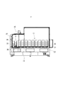
- FIG. 2 is a side view of the inside of the work stocker 7 as viewed from the relay device 5 side.
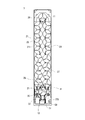
- FIG. 3 is a plan view showing the inside of the work stocker 7.
- a pallet moving device 11 that moves a plurality of pallets 21 in the circumferential direction along an oval path is formed on a base 15.
- three long positioning pins 23 are pushed upward with respect to the traveling base 22, and the pallet 21 is mounted on the traveling base 22 so as to be restrained by the positioning pins 23.
- the disk-shaped pallet 21 is mounted on the traveling table 22 in a state where three slits 211 are radially formed and are penetrated by three positioning pins 23.
- the pallet 21 can be moved in the vertical direction along the positioning pins 23 while maintaining a horizontal posture, and a plurality of works W can be stacked on it.
- a pallet moving device 11 As shown by a chain line in FIG. 3, an endless roller chain 24 is spanned in an oval shape, and a plurality of traveling platforms 22 are connected thereto.
- the roller chain 24 is stretched around a pair of sprockets 26 axially supported by arcuate portions at both ends in the longitudinal direction, and a moving motor is connected to one of the sprockets 26.
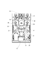
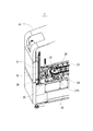
- 4 and 5 are a plan view and a perspective view showing the internal structure of the front part of the work stocker 7.
- a plurality of rollers 25 are attached on the base 15 along an elliptical path, and a plurality of traveling bases 22 connected to a roller chain 24 are supported by the rotating rollers 25 to move. .
- the plurality of traveling bases 22 connected to the roller chain 24 are moved all at once by the rotation control of the moving motor, and the predetermined pallet 21 is stopped at the delivery position P.
- the delivery position P is a position where the work W is delivered by the work transfer robot 4, and is provided at the end of the work stocker 7 in the longitudinal direction of the movement path.
- a work window 27 into which the work transfer robot 4 can enter is formed in the side wall of the machine body cover 16 so as to match the delivery position P in the range shown by the alternate long and short dash line in FIG.
- the work W is transferred between the work stocker 7 and the work transfer robot 4 at a transfer position P defined on the moving route and at a constant transfer height. Therefore, the work stocker 7 is provided with a pallet elevating device 12 for elevating the pallet 21 stopped at the delivery position P along the positioning pins 23.
- the pallet raising / lowering device 12 is provided at the front end of the work stocker 7, and the support column 31 is vertically erected and fixed to the base 15.
- a slide rail is vertically fixed to the column 31 on a side surface inside the machine, and an elevating table 33 is slidably attached to the slide rail.
- a pair of sprockets are pivotally supported on the upper and lower sides of the pillar 31, and the elevating table 33 is connected to the elevating chain that is hung on the sprocket.
- An elevating motor is connected to the lower sprocket, and the drive control thereof adjusts the height of the elevating table 33 according to the feed amount of the elevating chain.
- a support plate 35 for lifting the pallet 21 from below is fixed to the lift table 33.
- the support plate 35 has a bifurcated shape and is configured to support and lift the peripheral edge portion of the circular pallet 21 from below at three positions on the left and right sides and the root portion.
- the work W is received from the work transfer robot 4 when the pallet 21 stopped at the delivery position P further rises to a predetermined height and stops.
- the finished works W are sequentially carried and stacked on the empty pallet 21 stopped at the delivery position P. .
- the coolant drips to the delivery position P from the work W to which a large amount of coolant has adhered immediately after processing.
- the work stocker is formed such that the movement path of the pallet is an ellipse as in this embodiment, and an oil pan for receiving the coolant is provided on the floor surface inside the machine body that is long in the front-rear direction.
- the oil pan 37 is formed in the entire machine.
- the amount of the coolant that falls on the area is small.
- the amount of coolant dripping from the work W remains on the floor as it is.
- it is conceivable to incline the oil pan 37 but it is impossible because the oil pan 37 itself is a floor surface on which various parts are attached.
- the oil pan 37 of the present embodiment is configured so that the dripping coolant is likely to accumulate.
- a dam plate 38 is provided so as to partition a range corresponding to the delivery position P of the work W in the long oil pan 37 provided in the entire work stocker 7.
- the delivery position P is the place where the coolant is most likely to drop when the work W immediately after processing is introduced.
- the coolant collecting portion 370 having a small area is formed in a part of the oil pan 37.
- the range indicated by cross hatching in FIG. 4 corresponds to the coolant recovery unit 370.
- the work stocker 7 has an elliptical shape in which the moving path of the pallet 21 has a narrow width interval in the straight line portion, and the moving path of the pallet 21 is located at the folding end on the front side of the machine body.
- the delivery position P is set. Therefore, the coolant recovery unit 370 is configured by the dam plate 38 that partitions the end portion of the elongated oil pan 37 into small parts.
- the barrier plate 38 is formed so as to avoid the rollers 25, the sprocket 26, and the like, and connect the side walls on both sides in the width direction of the oil pan 37.
- a drain passage 39 is provided in the coolant recovery section 370 surrounded by the side wall of the oil pan 37 and the dam plate 38.
- the operation and effect of the work stocker 7 having the above configuration will be described.
- a plurality of pallets 21 are moved inside the machine by the pallet moving device 11, and the pallet 21 that receives the processed work W is positioned at the delivery position P.
- the feed amount of the roller chain 24 is specified by the rotation control of the moving motor, and a predetermined one of the plurality of traveling bases 22 that move in unison stops at the delivery position P.
- the pallet 21 arranged at the delivery position P is lifted to a predetermined height by the pallet lifting device 12.
- the pallet 21 alone is positioned so that the top surface of the pallet is at the delivery height, and when the work W is mounted on the pallet 21, the work upper surface is at the delivery height.
- the work W just after processing remains above the coolant recovery unit 370 until the five works W are mounted.
- the elevating table 33 is lowered, and the driving of the pallet moving device 11 is started to call the next empty pallet 21.
- the calling timing may be delayed so that the work W remains at the delivery position P until the next work W is carried.
- the work W which has been processed at an interval of approximately 1 minute, is carried to the work stocker 7. Then, depending on the processed shape of the work W, for example, about 15 milliliters of coolant, that is, about 1 tablespoon of coolant, drips from one work W. In the case of the work stocker used so far, this amount of coolant remains on the oil pan as described above, and only a part of the coolant flows into the drain passage, so that the coolant cannot be sufficiently recovered.
- the coolant collecting portion 370 that surrounds the delivery position P in a small size is configured, even if the coolant drips from the workpiece W little by little, As shown by cross-hatching in FIG. Therefore, evaporation of water from the coolant collected in the coolant recovery unit 370 is suppressed, and the collected coolant easily flows into the drain passage 39.
- the coolant recovery unit 370 of this embodiment is configured like a container having a height of the dam plate 38, that is, a depth of about 10 mm, and a volume of about 2 liters.
- the coolant recovery unit 370 will be filled in about 2 hours.
- the coolant recovery unit 370 has a size that allows the dripping coolant to easily accumulate. Therefore, even in a situation where about 15 milliliters of coolant drips every minute, the coolant is easily accumulated in the coolant recovery unit 370, and more coolant also flows into the drain passage 39. Therefore, the efficiency of collecting the coolant is significantly improved as compared with the conventional case.
- the dam plate 38 is provided on the conventional work stocker.
- the oil pan 37 serving as the coolant receiver has a vertically long shape with a small width dimension corresponding to the moving range of the oval pallet 21. Therefore, by partitioning the longitudinal end portion of the oil pan 37 in the lateral width direction with the dam plate 38, it is possible to easily form the coolant collecting portion 370 which is a small container in which even a small amount of coolant is likely to accumulate. Further, in the work stocker 7, the delivery position P is set at the folded back end of the movement path of the pallet 21, which is also a factor in the simple formation of the coolant recovery unit 370.
- the present invention is not limited to these, and various modifications can be made without departing from the spirit of the present invention.
- it may be a work stocker having a different structure, and the work delivery position of the work from the autoloader may be different, or the shape of the dam plate partitioning the range corresponding to the delivery position may be different. It may be different.
Landscapes
- Engineering & Computer Science (AREA)
- Mechanical Engineering (AREA)
- Auxiliary Devices For Machine Tools (AREA)
- Feeding Of Workpieces (AREA)
Abstract
クーラントの回収を行うワークストッカであって、ワークを搭載する複数のパレットを周状に並べて移動させるパレット移動装置と、前記パレットの移動範囲に対応して設けられたクーラント受けと、前記クーラント受けの一部であって、前記パレットの移動進路上に設けられたワークの受渡し位置に対応した範囲を仕切る堰板と、前記堰板によって仕切られた範囲に落下するクーラントを排出するドレン通路とを備える。
Description
本発明は、クーラントの回収を行うワークストッカに関する。
ワークを順に搬送して加工を行う加工機械ラインには、加工前のワークを投入するため或は、加工後のワークを回収するためにワークストッカが用いられる。そうした加工機械ラインにはオートローダが組み込まれ、ワーク搬送ロボットによって工作機械やワークストッカなどに対し、ワークの受渡しが自動で行われる。加工済みワークを回収するワークストッカには、各工程を経た加工済みワークが送り込まれるが、加工中にクーラントが大量に吹きかけられるため、ワーク表面に付着したクーラントが持ち込まれることとなる。そこで、ワークストッカにおいてもクーラントの回収が行われるようにすることが好ましい。この点に関する従来例としては、例えば下記特許文献1に、工作機械におけるクーラント液回収方法が開示されている。具体的には、ドレン通路やサブタンク内が吸引装置によって負圧にされ、その負圧によって吸引されたクーラントがサブタンク内に回収されるようになっている。
しかし、前記従来例のような工作機械におけるクーラントの回収は、大量のクーラントを扱うため吸引装置が使用される構成となっているが、ワークストッカには吸引装置を設置するようなスペースがない。しかも、ワークストッカには、吸引装置を使用するほどにクーラントが溜まるわけでもない。そのため、ワークストッカの構成は、回収されたワークが機内を移動する範囲にオイルパンが設けられ、ワークから滴り落ちるクーラントを受け取るようにしている。そしてオイルパンにはドレン通路が形成され、溜まったクーラントが回収可能になっているが、むしろ量が少ないためドレン通路にまで流れることなくオイルパンの上にとどまってしまう。そして、水分が蒸発したクーラントがオイルパンに汚れとして残ってしまうこととなる。
そこで、本発明は、かかる課題を解決すべく、クーラントの回収を行うワークストッカを提供することを目的とする。
本発明の一態様におけるワークストッカは、ワークを搭載する複数のパレットを周状に並べて移動させるパレット移動装置と、前記パレットの移動範囲に対応して設けられたクーラント受けと、前記クーラント受けの一部であって、前記パレットの移動進路上に設けられたワークの受渡し位置に対応した範囲を仕切る堰板と、前記堰板によって仕切られた範囲に落下するクーラントを排出するドレン通路とを備える。
前記構成によれば、パレット移動装置によって移動する複数のパレットの移動範囲に対応してクーラント受けが設けられているが、その一部であるワークの受渡し位置に対応した範囲が堰板によって仕切られているので、クーラントがその一部分に溜まり易くなり、ドレン通路にもより多くのクーラントが流れて回収できるようになる。
次に、本発明に係るワークストッカの一実施形態について、図面を参照しながら以下に説明する。本実施形態のワークストッカは加工機械ラインの一部として構成されたものであり、図1は、加工機械ラインの終端部分を示した正面図である。具体的には、ワークストッカと、中継装置および工作機械が示されている。加工機械ライン1は、複数台の工作機械3が横並びに配置され、加工順に従ってワークWを搬送するオートローダが組み込まれている。加工機械ライン1には、前面部分にワーク搬送ロボット4が移動する搬送空間が形成され、工作機械3の前方側からワークの受け渡しが行われるようになっている。
各工程の加工を終了したワークWは、中継装置5やワークストッカ7へと送り込まれる。中継装置5には仮置き台501が設けられ、そこに置かれた加工済みのワークWに対して検測などが行われるようになっている。中継装置5やワークストッカ7には、図示するように、多関節のワーク搬送ロボット4が横方向から進入してワークWの受渡しが行われる。ワークストッカ7に対しては、中継装置5を通り越してワーク搬送ロボット4が届くように、中継装置5の横幅寸法が小さく設計されている。本実施形態では、工作機械3やワークストッカ7の横幅が450mmとコンパクトであるが、中継装置5は更にその半分の225mmである。
ここで、図2は、ワークストッカ7を中継装置5側から示した内部の側面図である。また、図3は、ワークストッカ7の内部を示した平面図である。ワークストッカ7は、複数のパレット21を長円形の進路に従って周方向に移動させるパレット移動装置11がベース15の上に構成されている。パレット移動装置11は、走行台22に対して3本の長い位置決めピン23が上方に突き立てられており、パレット21は、この位置決めピン23に拘束されるようにして走行台22の上に搭載されている。円盤形状のパレット21は、放射状に3つのスリット211が形成され、3本の位置決めピン23によってそれぞれが貫かれた状態で走行台22に搭載されている。
パレット21は、水平な姿勢を保ちながら、位置決めピン23に沿って鉛直方向の移動が可能であり、その上には複数のワークWが積み上げられるようになっている。パレット移動装置11は、図3に一点鎖線で示すように、無端のローラチェーン24が長円形になるように掛け渡され、そこに複数の走行台22が連結されている。そのローラチェーン24は、長手方向両端の円弧部に軸支された一対のスプロケット26に掛け渡されており、一方のスプロケット26には移動用モータが連結されている。ここで、図4および図5は、ワークストッカ7の前部の内部構造を示した平面図と斜視図である。
ベース15上には長円形の進路に従って複数のローラ25が取り付けられており、ローラチェーン24に連結された複数の走行台22が、回転するローラ25に支えられて移動する構成がとられている。パレット移動装置11では、移動用モータの回転制御によって、ローラチェーン24に連結された複数の走行台22が一斉に移動し、所定のパレット21が受渡し位置Pに止められるようになっている。受渡し位置Pは、ワーク搬送ロボット4によってワークWの受渡しが行われる位置であり、ワークストッカ7では移動進路の長手方向端部に設けられている。そして、その受渡し位置Pに合わせるように、機体カバー16の側壁には、図2において一点鎖線で示すような範囲に、ワーク搬送ロボット4が進入可能な作業窓27が形成されている。
ワークストッカ7におけるワーク搬送ロボット4とのワークWの受渡しは、移動進路上に定められた受渡し位置Pであって、更に一定の受渡し高さで行われるようになっている。そのためワークストッカ7には、受渡し位置Pに停止したパレット21を位置決めピン23に沿って昇降させるパレット昇降装置12が設けられている。パレット昇降装置12は、ワークストッカ7の前端部に設けられ、ベース15に対して支柱31が鉛直方向に起立して固定されている。その支柱31には、機内側の側面にスライドレールが鉛直方向に固定され、そのスライドレールに対して昇降台33が摺動自在に組み付けられている。
また、パレット昇降装置12は、支柱31内部の上下に一対のスプロケットが軸支され、そこに掛け渡された昇降チェーンに昇降台33が連結されている。下方のスプロケットには昇降用モータが連結され、その駆動制御によって昇降チェーンの送り量に従った昇降台33の高さ調節が行われるようになっている。そして、昇降台33にはパレット21を下から持ち上げるための支持プレート35が固定さている。支持プレート35は、二股形状であって、円形のパレット21の周縁部分を左右両側と付け根部分の3個所において、下から支えて持ち上げるようにしたものである。
ワークストッカ7では、受渡し位置Pに停止したパレット21が更に所定の高さにまで上昇して停止することにより、ワーク搬送ロボット4からのワークWの受け取りが行われる。本実施形態では一つのパレット21に5つのワークWが搭載可能であるため、受渡し位置Pに停止した空のパレット21には、加工を終えたワークWが順番に運ばれて積み重ねられることとなる。その間、加工直後でクーラントが大量に付着したワークWからは、受渡し位置Pにクーラントが滴り落ちることになる。
一般的にワークストッカは、本実施形態のようにパレットの移動進路が長円形になるように形成され、前後方向に長い機体内部の床面にはクーラントを受けるオイルパンが設けられている。本実施形態のワークストッカ7でも機内全体にオイルパン37が形成されている。しかし、ワークストッカの場合、オイルパンによってクーラントを受けたとしても、その面積に対して落ちるクーラントの量が少ない。前記課題でも述べたように、ワークWから滴り落ちる量のクーラントは、そのまま床面にとどまってしまう。また、滴り落ちたクーラントがある程度の量溜まったとしても、横に広がるだけでドレン通路には一部しか流れず、十分な回収ができなかった。この点、オイルパン37に傾斜を付けることが考えられるが、オイルパン37自体が様々な部品が取り付けられている床面であるため不可能である。
そこで、本実施形態のオイルパン37には、滴り落ちたクーラントが溜まり易いような構成がとられている。具体的には、ワークストッカ7全体に設けられた長尺なオイルパン37のうち、ワークWの受渡し位置Pに対応した範囲を仕切るようにした堰板38が設けられている。受渡し位置Pは、加工直後のワークWが投入された最もクーラントが落ちやすい箇所である。そして、その個所に堰板38を設けることにより、オイルパン37の一部に小さな面積のクーラント回収部370が形成されている。図4にクロスハッチングで示した範囲がクーラント回収部370に相当する部分である。
ワークストッカ7は、図3に示すように、パレット21の移動進路が、直線部分の幅間隔が狭くなるようにした長円形であって、そうした移動進路のうち、機体前方側の折返し端部に受渡し位置Pが設定されている。よって、クーラント回収部370は、細長く形成されたオイルパン37の端部を小さく仕切った堰板38により構成されている。堰板38は、ローラ25やスプロケット26などを避け、オイルパン37の幅方向両側の側壁を繋ぐようにして形成されている。そして、オイルパン37の側壁と堰板38によって囲まれたクーラント回収部370内にドレン通路39が設けられている。
続いて、以上のような構成のワークストッカ7における作用効果を説明する。ワークストッカ7は、パレット移動装置11によって複数のパレット21が機内を移動し、加工済みワークWを受け取るパレット21が受渡し位置Pに位置決めされる。具体的には、移動用モータに対する回転制御によって、ローラチェーン24の送り量が特定され、一斉に移動する複数の走行台22のうち所定のものが受渡し位置Pに合わせて停止する。そして、受渡し位置Pに配置されたパレット21は、パレット昇降装置12によって所定の高さにまで持ち上げられる。
従って、ワークWの受渡しは、パレット21だけの場合には、パレット上面が受渡し高さになるように位置決めされ、パレット21にワークWが搭載されている場合には、ワーク上面が受渡し高さになるように位置決めされる。一つのパレット21には、5個のワークWが一定の間隔で運ばれ順番に重ねられていく。そのため、5個のワークWが搭載されるまでの間、加工直後のワークWがクーラント回収部370の上方にとどまることとなる。そして、最後のワークWが搭載されると昇降台33が下降し、次の空きパレット21を呼び出すためにパレット移動装置11の駆動が開始する。ただし、加工済みのワークWからより多くのクーラントがクーラント回収部370に落ちるようにすることが好ましい。よって、呼び出しタイミングを遅らせ、例えば、次のワークWが運ばれるまで受渡し位置Pにとどまらせるようにしてもよい。
ところで、本実施形態の加工機械ライン1では、概ね1分間隔で加工を終えたワークWがワークストッカ7へと運ばれる。そして、ワークWの加工形状などにもよるが、例えば1個のワークWから約15ミリリットルつまり大さじ1杯分程度のクーラントが滴り落ちる。これまでのワークストッカであれば、この程度のクーラントは、前述したようにオイルパンの上にとどまってしまい、ドレン通路には一部しか流れず、十分な回収ができなかった。
この点、本実施形態では、受渡し位置Pの周りを小さく囲んだクーラント回収部370を構成したことにより、ワークWから滴り落ちる僅かずつのクーラントであっても、そのクーラント回収部370内には、図4においてクロスハッチングで示すように溜まるようになる。そのため、クーラント回収部370に溜まるクーラントからは水分の蒸発は抑えられ、また溜まったクーラントはドレン通路39へと流れ易くなる。
例えば、本実施形態のクーラント回収部370は、堰板38の高さつまり深さが10mm程度で約2リットル分の体積をもった容器のように構成されている。前述したように、1分間に15ミリリットルのクーラントが滴り落ちるとした場合、仮にドレン通路39を塞いだ状態で溜めたとすると、クーラント回収部370は、2時間程度で満たされることとなる。このようにクーラント回収部370は、滴り落ちるクーラントが溜まり易い大きさであるといえる。そのため、1分ごとに15ミリリットル程度のクーラントが滴り落ちるような状況であっても、クーラント回収部370はクーラントが溜まり易く、ドレン通路39にもより多くのクーラントが流れるようになる。よって、従来に比べて大幅にクーラントの回収効率が良くなる。
しかも、このような効果を、従来のワークストッカに対し堰板38を設けるだけの簡単な構成によって達成することができる。そして、ワークストッカ7は、クーラント受けであるオイルパン37が、長円形をしたパレット21の移動範囲に対応する幅寸法の小さい縦長形状である。そのため、オイルパン37の長手方向端部を横幅方向に堰板38で仕切ることにより、少量のクーラントであっても溜まり易い小さな容器となるクーラント回収部370が簡単に形成できる。また、ワークストッカ7は、パレット21の移動進路のうち、折返し端部に受渡し位置Pが設定されていることも、クーラント回収部370の簡単な形成の要因になっている。
以上、本発明の一実施形態について説明したが、本発明はこれらに限定されるものではなく、その趣旨を逸脱しない範囲で様々な変更が可能である。
例えば、本発明に従って構成を有するものであれば、異なる構造のワークストッカであってもよく、オートローダからのワークの受渡し位置が異なるもの或いは、受渡し位置に対応した範囲を仕切る堰板の形状などが異なるものであってもよい。
例えば、本発明に従って構成を有するものであれば、異なる構造のワークストッカであってもよく、オートローダからのワークの受渡し位置が異なるもの或いは、受渡し位置に対応した範囲を仕切る堰板の形状などが異なるものであってもよい。
1…加工機械ライン 3…工作機械 4…ワーク搬送ロボット 5…中継装置 7…ワークストッカ 11…パレット移動装置 12…パレット昇降装置 21…パレット 24…ローラチェーン 33…昇降台 35…支持プレート 37…オイルパン 38…堰板 39…ドレン通路 370…クーラント回収部 P…受渡し位置 W…ワーク
Claims (3)
- ワークを搭載する複数のパレットを周状に並べて移動させるパレット移動装置と、
前記パレットの移動範囲に対応して設けられたクーラント受けと、
前記クーラント受けの一部であって、前記パレットの移動進路上に設けられたワークの受渡し位置に対応した範囲を仕切る堰板と、
前記堰板によって仕切られた範囲に落下するクーラントを排出するドレン通路と、
を備えたワークストッカ。 - 前記クーラント受けは、長円形をした前記パレットの移動範囲に対応する縦長形状であって、前記堰板が、前記クーラント受けの長手方向端部を横幅方向に仕切るように設けられた請求項1に記載のワークストッカ。
- 前記ワークの受渡し位置は、長円形をした前記パレットの移動範囲の折り返し位置である請求項1又は請求項2に記載のワークストッカ。
Priority Applications (2)
| Application Number | Priority Date | Filing Date | Title |
|---|---|---|---|
| PCT/JP2018/038834 WO2020079804A1 (ja) | 2018-10-18 | 2018-10-18 | ワークストッカ |
| JP2020551672A JP6995218B2 (ja) | 2018-10-18 | 2018-10-18 | ワークストッカ |
Applications Claiming Priority (1)
| Application Number | Priority Date | Filing Date | Title |
|---|---|---|---|
| PCT/JP2018/038834 WO2020079804A1 (ja) | 2018-10-18 | 2018-10-18 | ワークストッカ |
Publications (1)
| Publication Number | Publication Date |
|---|---|
| WO2020079804A1 true WO2020079804A1 (ja) | 2020-04-23 |
Family
ID=70283201
Family Applications (1)
| Application Number | Title | Priority Date | Filing Date |
|---|---|---|---|
| PCT/JP2018/038834 Ceased WO2020079804A1 (ja) | 2018-10-18 | 2018-10-18 | ワークストッカ |
Country Status (2)
| Country | Link |
|---|---|
| JP (1) | JP6995218B2 (ja) |
| WO (1) | WO2020079804A1 (ja) |
Cited By (1)
| Publication number | Priority date | Publication date | Assignee | Title |
|---|---|---|---|---|
| JPWO2022201368A1 (ja) * | 2021-03-24 | 2022-09-29 |
Citations (5)
| Publication number | Priority date | Publication date | Assignee | Title |
|---|---|---|---|---|
| JPH02188306A (ja) * | 1989-01-13 | 1990-07-24 | Daifuku Co Ltd | 棚装置 |
| JPH0672933U (ja) * | 1993-03-31 | 1994-10-11 | 株式会社森精機製作所 | ワークストッカ |
| JP2004522100A (ja) * | 2001-04-21 | 2004-07-22 | ツェットエフ、フリードリッヒスハーフェン、アクチエンゲゼルシャフト | 油供給装置 |
| JP2013086952A (ja) * | 2011-10-21 | 2013-05-13 | Citizen Holdings Co Ltd | 製品回収装置 |
| JP2017052055A (ja) * | 2015-09-10 | 2017-03-16 | 富士機械製造株式会社 | ワーク搬送装置および工作機械 |
Family Cites Families (3)
| Publication number | Priority date | Publication date | Assignee | Title |
|---|---|---|---|---|
| KR200410150Y1 (ko) | 2005-11-24 | 2006-03-07 | 현대중공업 주식회사 | 회전형 컨베이어용 오일받이장치 |
| CN204997443U (zh) | 2015-09-25 | 2016-01-27 | 东莞市汉亚工业自动化设备有限公司 | 一种具有机械手和旋转仓上下料的机床 |
| JP6815626B2 (ja) * | 2016-11-08 | 2021-01-20 | 昭和電機株式会社 | オイルミスト除去装置 |
-
2018
- 2018-10-18 WO PCT/JP2018/038834 patent/WO2020079804A1/ja not_active Ceased
- 2018-10-18 JP JP2020551672A patent/JP6995218B2/ja not_active Expired - Fee Related
Patent Citations (5)
| Publication number | Priority date | Publication date | Assignee | Title |
|---|---|---|---|---|
| JPH02188306A (ja) * | 1989-01-13 | 1990-07-24 | Daifuku Co Ltd | 棚装置 |
| JPH0672933U (ja) * | 1993-03-31 | 1994-10-11 | 株式会社森精機製作所 | ワークストッカ |
| JP2004522100A (ja) * | 2001-04-21 | 2004-07-22 | ツェットエフ、フリードリッヒスハーフェン、アクチエンゲゼルシャフト | 油供給装置 |
| JP2013086952A (ja) * | 2011-10-21 | 2013-05-13 | Citizen Holdings Co Ltd | 製品回収装置 |
| JP2017052055A (ja) * | 2015-09-10 | 2017-03-16 | 富士機械製造株式会社 | ワーク搬送装置および工作機械 |
Cited By (2)
| Publication number | Priority date | Publication date | Assignee | Title |
|---|---|---|---|---|
| JPWO2022201368A1 (ja) * | 2021-03-24 | 2022-09-29 | ||
| WO2022201368A1 (ja) * | 2021-03-24 | 2022-09-29 | 株式会社Fuji | ストッカ機能付き無人搬送車およびワーク無人搬送システム |
Also Published As
| Publication number | Publication date |
|---|---|
| JPWO2020079804A1 (ja) | 2021-06-03 |
| JP6995218B2 (ja) | 2022-01-14 |
Similar Documents
| Publication | Publication Date | Title |
|---|---|---|
| US9339907B2 (en) | Chip disposal device of machine tool | |
| DE102015207122B3 (de) | Werkzeugmaschine mit einer Werkstückauflage und Verfahren zum Be- und Entladen einer Werkstückauflage einer Werkzeugmaschine | |
| CN103056532B (zh) | 激光切割机单机自动上下料装置及方法 | |
| KR102022627B1 (ko) | 피도금물 공급 및 배출설비 | |
| JP7577006B2 (ja) | 加工装置 | |
| KR101003722B1 (ko) | 트레이 반송 시스템 | |
| JP6995218B2 (ja) | ワークストッカ | |
| CN110625833B (zh) | 一种用于晶硅的上下料单元及上下料方法 | |
| JP6360383B2 (ja) | ワークの一枚取り装置 | |
| CN111039001A (zh) | 袋装槟榔自动存储码垛设备 | |
| CN110654058B (zh) | 一种纸胚自动折盒设备及其自动折盒机构 | |
| CN102372097B (zh) | 奶杯翻转整合装置 | |
| CN119262659A (zh) | 一种防物流干涉的清洗车间上料装置 | |
| CN117622867B (zh) | 一种自动换载具设备 | |
| KR20160074855A (ko) | 산세·피막 처리 시스템 | |
| JP4775941B2 (ja) | 廃自動車の液類回収システム | |
| JP2011094193A (ja) | キャリア式めっき装置 | |
| CN117124120A (zh) | 一种用于机床的上下料机器人及上下料方法 | |
| JPH0534821Y2 (ja) | ||
| JP3692968B2 (ja) | ローテーション式移載装置 | |
| JPH02185342A (ja) | 出し入れ装置を有する加工設備 | |
| CN111807065A (zh) | 上料装置及上料方法 | |
| CN223222959U (zh) | 一种用于双轴双面倒角机的废料处理结构 | |
| JPS59138526A (ja) | 受皿の自動循環移送装置 | |
| KR100859841B1 (ko) | 엔진밸브 자동 파킹장치 |
Legal Events
| Date | Code | Title | Description |
|---|---|---|---|
| 121 | Ep: the epo has been informed by wipo that ep was designated in this application |
Ref document number: 18937181 Country of ref document: EP Kind code of ref document: A1 |
|
| ENP | Entry into the national phase |
Ref document number: 2020551672 Country of ref document: JP Kind code of ref document: A |
|
| NENP | Non-entry into the national phase |
Ref country code: DE |
|
| 122 | Ep: pct application non-entry in european phase |
Ref document number: 18937181 Country of ref document: EP Kind code of ref document: A1 |