WO2020071485A1 - 炭素系物質振動子、並びにこれを備えたセンサー素子及び生体由来物質検出装置 - Google Patents
炭素系物質振動子、並びにこれを備えたセンサー素子及び生体由来物質検出装置Info
- Publication number
- WO2020071485A1 WO2020071485A1 PCT/JP2019/039111 JP2019039111W WO2020071485A1 WO 2020071485 A1 WO2020071485 A1 WO 2020071485A1 JP 2019039111 W JP2019039111 W JP 2019039111W WO 2020071485 A1 WO2020071485 A1 WO 2020071485A1
- Authority
- WO
- WIPO (PCT)
- Prior art keywords
- vibrator
- substance
- carbon
- group
- based material
- Prior art date
- Legal status (The legal status is an assumption and is not a legal conclusion. Google has not performed a legal analysis and makes no representation as to the accuracy of the status listed.)
- Ceased
Links
Images

Classifications
-
- G—PHYSICS
- G01—MEASURING; TESTING
- G01N—INVESTIGATING OR ANALYSING MATERIALS BY DETERMINING THEIR CHEMICAL OR PHYSICAL PROPERTIES
- G01N33/00—Investigating or analysing materials by specific methods not covered by groups G01N1/00 - G01N31/00
- G01N33/48—Biological material, e.g. blood, urine; Haemocytometers
- G01N33/483—Physical analysis of biological material
-
- G—PHYSICS
- G01—MEASURING; TESTING
- G01N—INVESTIGATING OR ANALYSING MATERIALS BY DETERMINING THEIR CHEMICAL OR PHYSICAL PROPERTIES
- G01N29/00—Investigating or analysing materials by the use of ultrasonic, sonic or infrasonic waves; Visualisation of the interior of objects by transmitting ultrasonic or sonic waves through the object
- G01N29/04—Analysing solids
- G01N29/12—Analysing solids by measuring frequency or resonance of acoustic waves
-
- G—PHYSICS
- G01—MEASURING; TESTING
- G01N—INVESTIGATING OR ANALYSING MATERIALS BY DETERMINING THEIR CHEMICAL OR PHYSICAL PROPERTIES
- G01N29/00—Investigating or analysing materials by the use of ultrasonic, sonic or infrasonic waves; Visualisation of the interior of objects by transmitting ultrasonic or sonic waves through the object
- G01N29/22—Details, e.g. general constructional or apparatus details
- G01N29/24—Probes
- G01N29/2418—Probes using optoacoustic interaction with the material, e.g. laser radiation, photoacoustics
-
- G—PHYSICS
- G01—MEASURING; TESTING
- G01N—INVESTIGATING OR ANALYSING MATERIALS BY DETERMINING THEIR CHEMICAL OR PHYSICAL PROPERTIES
- G01N29/00—Investigating or analysing materials by the use of ultrasonic, sonic or infrasonic waves; Visualisation of the interior of objects by transmitting ultrasonic or sonic waves through the object
- G01N29/44—Processing the detected response signal, e.g. electronic circuits specially adapted therefor
- G01N29/4409—Processing the detected response signal, e.g. electronic circuits specially adapted therefor by comparison
- G01N29/4418—Processing the detected response signal, e.g. electronic circuits specially adapted therefor by comparison with a model, e.g. best-fit, regression analysis
-
- G—PHYSICS
- G01—MEASURING; TESTING
- G01N—INVESTIGATING OR ANALYSING MATERIALS BY DETERMINING THEIR CHEMICAL OR PHYSICAL PROPERTIES
- G01N2291/00—Indexing codes associated with group G01N29/00
- G01N2291/02—Indexing codes associated with the analysed material
- G01N2291/025—Change of phase or condition
- G01N2291/0255—(Bio)chemical reactions, e.g. on biosensors
-
- G—PHYSICS
- G01—MEASURING; TESTING
- G01N—INVESTIGATING OR ANALYSING MATERIALS BY DETERMINING THEIR CHEMICAL OR PHYSICAL PROPERTIES
- G01N2291/00—Indexing codes associated with group G01N29/00
- G01N2291/02—Indexing codes associated with the analysed material
- G01N2291/025—Change of phase or condition
- G01N2291/0256—Adsorption, desorption, surface mass change, e.g. on biosensors
Definitions
- the present invention relates to a carbon-based material oscillator, a sensor element provided with the same, and a biological substance detection device.
- biosensors based on the reaction of biological substances such as antigens, enzymes, hormones, and DNA with specific substances have been widely used to detect the reaction as a physical change, a thermal change, a chemical change, and the like. It's being used.
- Patent Literature 1 discloses a sensor element including a substrate, a surface formed on the substrate to which a protein that supplements a detection target is fixed, and including a metal thin film that vibrates when irradiated with laser light. I have.
- Patent Document 2 discloses a solid support in which a surface treatment layer is formed on a quartz oscillator that is an element having an electro-mechanical conversion function, and the surface treatment layer is diamond, diamond-like carbon, or the like.
- a biosensor in which a physiologically active substance is immobilized on a substrate obtained by chemically modifying the surface of a solid support is disclosed.
- Patent Document 1 it is difficult to make the thickness of the piezoelectric vibrator thinner than several tens ⁇ m in order to maintain the mechanical strength of the resonance vibrator mass detection device using the conventional piezoelectric vibrator. As a result, he pointed out that there is a problem that the sensitivity of the resonance vibrator mass detection device is low. According to Patent Document 1, since the first metal thin film is formed on the substrate, the thickness of the first metal thin film is reduced. It is described that it can be thinned.
- an object of the present invention is to provide a vibrator that can vibrate without electrodes and has good vibration continuity. It is preferable that the vibrator of the present invention further has good detection sensitivity and does not damage the immobilized protein and the like.
- the present invention is as follows. [1] A carbon-based material oscillator for light irradiation vibration, on which a biological substance or a substance having discriminability from the biological substance is fixed. [2] The vibrator according to [1], which does not have a counter electrode for applying a voltage to the vibrator. [3] The vibrator according to [1] or [2], wherein the carbon-based material is graphite. [4] The method according to any one of [1] to [3], wherein the thermal conductivity ⁇ 1 in the plane direction of the carbon-based material is 100 times or more the thermal conductivity ⁇ 2 in the thickness direction of the carbon-based material. Vibrator.
- a sensor element comprising the vibrator according to any one of [1] to [4] and a holding member.
- the sensor element according to [5] further comprising a microchannel.
- a living body-derived substance detection device comprising: a detector that measures a vibration displacement of a vibrator based on a reflectance of probe light reflected by the vibrator and detects a living body-derived substance.
- the vibrator of the present invention can be vibrated by light irradiation even without electrodes like a piezoelectric vibrator, and can maintain vibration for a long time. Furthermore, in a preferred embodiment of the present invention, since the thermal conductivity in the out-of-plane direction is low, the heat flow generated by light irradiation escapes mainly in the in-plane direction, and the influence of heating of proteins and the like immobilized on the surface is reduced. It is greatly reduced, and inactivation of proteins and the like can be prevented. As a result, in a preferred embodiment of the present invention, the vibrator can be further thinned, and the detection sensitivity can be greatly improved.
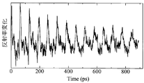
- FIG. 4 is a waveform diagram illustrating vibration of the graphite vibrator of Example 1 (1).
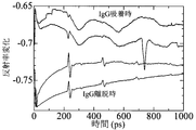
- FIG. 6 is a waveform chart showing vibration of the biosensor of Example 1 (2).
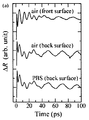
- FIG. 9 is a waveform diagram illustrating vibration of a Pt vibrator of Comparative Example 1.
- the present invention is a carbon-based material vibrator to which a biological substance or a substance having discriminability from the biological substance is fixed, and is a vibrator that is vibrated by light irradiation. Therefore, the carbon-based material vibrator of the present invention does not usually have a counter electrode for applying a voltage to the vibrator, such as a piezoelectric vibrator does.
- the carbon-based material only needs to contain a carbon atom as a component, and may be amorphous carbon, crystalline carbon, or metal carbide.
- amorphous carbon examples include amorphous carbon and diamond-like carbon.
- Diamond-like carbon is amorphous carbon in which carbon having sp 3 bonds and carbon having sp 2 bonds are mixed irregularly.
- the amorphous carbon include a film obtained by heat-treating a polymer film of an aromatic polyimide or the like at about 900 to 1000 ° C. in an inert gas atmosphere. It is at least 30% by mass and not less than 30% by mass.
- graphite is mentioned as crystalline carbon.
- the metal carbide examples include molybdenum carbide, tungsten carbide, titanium carbide and the like.
- the carbon-based material is preferably graphite, and the graphite vibrator has a sufficiently lower mass density than metal and is smaller than other carbon materials, so that the mass detection sensitivity of the target biological substance is good, and Damage to the derived substance or the substance having discriminability from the living body-derived substance can be suppressed.
- it since it has the advantage of high strength as a self-supporting film, it can be used as a vibrator without a substrate, and the continuity of vibration that can be evaluated based on the Q value of vibration can be further improved.
- the ratio of amorphous carbon to graphite can be known by measuring the carbon-based material by laser Raman. Amorphous carbon appearing at around 1350-1360 cm -1 with respect to the intensity I (G) of the G band caused by the graphite structure appearing around 1575-1600 cm -1 when the carbon-based material in the present invention was measured by laser Raman spectroscopy
- the ratio of the intensity I (D) of the D band due to the structure (I (D) / I (G)) of 0 or more and 0.7 or less is referred to as graphite.
- (I (D) / I (G)) of graphite is preferably 0 or more and 0.5 or less, more preferably 0 or more and 0.1 or less, and particularly preferably 0 or more and 0.05 or less.
- a vibrator made of graphite having a value of I (D) / I (G) of 0.5 or less has a low mass density and therefore has a high detection sensitivity for a substance derived from a living body, and has an out-of-plane thermal conductivity of in-plane. Since it is sufficiently smaller than the thermal conductivity, the influence of heating by light irradiation on the back surface does not affect the biological substance to be detected on the front surface, and the damage can be suppressed, which is preferable.
- the shape of the carbon-based material constituting the vibrator of the present invention is not particularly limited, and examples thereof include a polygonal film such as a square and a rectangle, a circular film, and an elliptical film.
- the area of the vibrator is, for example, 4 mm 2 or more and 400 mm 2 or less.
- the thickness of the carbon-based material is preferably 10 nm or more.
- the thickness of the carbon-based material is more preferably 20 nm or more, still more preferably 30 nm or more, and still more preferably 50 nm or more.
- the upper limit of the thickness of the carbon-based material is, for example, 1000 nm or less, and in particular, in the case where a biological substance is detected using the resonance method described below, the thickness of the carbon-based material is preferably 500 nm or less.
- the thickness of the carbon-based material is 500 nm or less because resonance of the vibrator can be caused without generating an elastic pulse wave having a uniform phase in the vibrator.
- the thickness of the carbon-based material is more preferably 200 nm or less, and still more preferably 100 nm or less.
- the orientation of the crystallites of graphite in the c-axis direction can be evaluated by mosaic spread.
- the mosaic spread can be measured with an X-ray diffractometer.
- a counter (2 ⁇ axis) of an X-ray diffraction apparatus is fixed at a position where the X-ray diffraction line on the (002) plane of the plate-like graphite film shows a peak.
- an intensity function sample azimuth angle dependency curve of (002) plane diffraction line peak intensity
- ⁇ ⁇ ⁇ The smaller the value of the mosaic spread, the higher the orientation in the c-axis direction. If the value of the mosaic spread is large, that is, if the orientation of the graphite crystallites in the c-axis direction is low, the arrangement of the six-membered rings in the c-axis direction is irregular, so that the graphite tends to become brittle.
- a mosaic spread of 0.3 ° indicates that a deviation of the c-axis from a direction perpendicular to the six-membered ring connected body (plate surface) is within approximately ⁇ 0.6 ° (carbon terminology). Encyclopedia, Editorial Committee for Carbon Glossary, Carbon Material Society of Japan, K.
- the mosaic spread of graphite is preferably 3.0 ° or less, more preferably 1.5 ° or less, and further preferably 0.5 ° or less. Further, when the mosaic spread is 5.0 ° or less, there is an advantage that the heat dissipation of graphite is excellent.
- the lower limit of the mosaic spread is, for example, 0.1 ° or more.
- the mosaic spread can be adjusted by the temperature and pressure during the firing process during the production of graphite.
- the thermal conductivity ⁇ 1 in the plane direction of the carbon-based material is preferably 100 times or more as large as the thermal conductivity ⁇ 2 in the thickness direction of the carbon-based material.
- the thermal conductivity ⁇ 1 in the plane direction is sufficiently larger than the thermal conductivity ⁇ 2 in the thickness direction, heat generated in the vibrator by light irradiation can be suppressed from being conducted in the vibrator thickness direction. Since the heat escapes in the direction, it is possible to suppress the inactivation of the biological material fixed to the vibrator on the surface opposite to the light irradiation surface, the material having discrimination from the biological material, and the biological material to be detected.
- the ratio of the thermal conductivity ⁇ 1 in the plane direction to the thermal conductivity ⁇ 2 in the thickness direction of the carbon-based material is more preferably 200 times or more, and the upper limit is not particularly limited, but is, for example, 300 times.
- the sensitivity is inversely proportional to the density of the vibrator and inversely proportional to the square of the thickness of the vibrator. Therefore, by using a carbon-based material as a vibrator, detection sensitivity is improved by 10 times or more as compared with a conventional metal.
- the carbonaceous material is preferably density of 2.26 g / cm 3 or less, more preferably 2.2 g / cm 3 or less. The lower limit of the density may be, for example, 2.0 g / cm 3 .
- the diamond-like carbon vibrator may be formed by a physical vapor deposition method (sputtering method, arc ion plating method, ion vapor deposition method, etc.) using solid carbon as a raw material, or carbonization. It can be manufactured by a chemical vapor deposition method using a hydrogen-based gas as a raw material (plasma CVD method, thermal CVD method, photo-CVD method, etc.).
- the amorphous carbon vibrator can be formed by, for example, performing a physical vapor deposition method such as a vacuum vapor deposition method, or carbonizing heat treatment of a polymer film such as an aromatic polyimide to convert amorphous carbon. It can be manufactured by a method for obtaining the same.
- the carbonization heat treatment may be performed at about 900 to 1000 ° C. for 15 to 30 minutes in an inert gas atmosphere such as nitrogen, argon, or a mixed gas of argon and nitrogen.
- the graphite vibrator When the vibrator of the present invention is a graphite vibrator, the graphite vibrator obtains an amorphous carbon film by performing a carbonization heat treatment on a polymer film such as an aromatic polyimide, and heats the amorphous carbon film at a high temperature.
- a graphitization heat treatment in an inert gas such as argon gas or a mixed gas of argon gas and helium gas at 2200 ° C. or more (preferably 2600 ° C. or more) for 15 to 30 minutes (firing). It can be manufactured by
- the heat treatment temperature in the graphitization is more preferably 2800 ° C. or higher, further preferably 3000 ° C. or higher, and the upper limit is not particularly limited, but is, for example, 3600 ° C. or lower.
- the polymer preferably used as a raw material of the amorphous carbon oscillator or the graphite oscillator is an aromatic polymer, and as the aromatic polymer, polyamide, polyimide, polyquinoxaline, polyparaphenylene vinylene, polyoxadiazole, It is preferably at least one selected from polybenzimidazole, polybenzoxazole, polybenzthiazole, polyquinazolinedione, polybenzoxazinone, polyquinazolone, benzimidazobenzophenanthroline ladder polymer, and derivatives thereof.
- the film made of these polymers may be manufactured by a known manufacturing method.
- Particularly preferred polymers include aromatic polyimide, polyparaphenylenevinylene, and polyparaphenyleneoxadiazole.
- an aromatic polyimide is preferable, and among them, an aromatic polyimide produced from a dianhydride (particularly, an aromatic dianhydride) and a diamine (particularly, an aromatic diamine) via a polyamic acid is particularly preferable.
- Examples of the acid dianhydride that can be used for the synthesis of the aromatic polyimide include pyromellitic dianhydride, 2,3,6,7-naphthalenetetracarboxylic dianhydride, 3,3 ′, 4,4′- Biphenyltetracarboxylic dianhydride, 1,2,5,6-naphthalenetetracarboxylic dianhydride, 2,2 ′, 3,3′-biphenyltetracarboxylic dianhydride, 3,3 ′, 4,4 '-Benzophenonetetracarboxylic dianhydride, 2,2-bis (3,4-dicarboxyphenyl) propane dianhydride, 3,4,9,10-perylenetetracarboxylic dianhydride, bis (3,4 -Dicarboxyphenyl) propane dianhydride, 1,1-bis (2,3-dicarboxyphenyl) ethane dianhydride, 1,1-bis (3,4-dicarboxyphen
- Diamines that can be used in the synthesis of the aromatic polyimide include 4,4′-diaminodiphenylpropane, 4,4′-diaminodiphenylmethane, benzidine, 3,3′-dichlorobenzidine, 4,4′-diaminodiphenyl sulfide, 3,3'-diaminodiphenylsulfone, 4,4'-diaminodiphenylsulfone, 4,4'-diaminodiphenylether, 3,3'-diaminodiphenylether, 3,4'-diaminodiphenylether, 1,5-diaminonaphthalene, 4,4'-diaminodiphenyldiethylsilane, 4,4'-diaminodiphenylsilane, 4,4'-diaminodiphenylethylphosphine oxide, 4,4'-diaminodiphenylN-
- the polyimide film is particularly preferable to synthesize the polyimide film using 4,4'-diaminodiphenyl ether or p-phenylenediamine as a raw material.
- the production method includes a heat curing method in which the precursor polyamic acid is imide-converted by heating, a dehydrating agent represented by an acid anhydride such as acetic anhydride to the polyamic acid, and picoline.
- a chemical curing method in which tertiary amines such as quinoline, isoquinoline, pyridine and the like are used as an imidization accelerator, and imide conversion is performed, and any of them may be used.
- the resulting film has a small coefficient of linear expansion, a high elastic modulus, and a large birefringence.It is possible to obtain a graphite film of good quality without breaking even if tension is applied during firing of the film.
- the chemical curing method is preferable from the viewpoint that it can be performed.
- the chemical cure method is also excellent in improving the thermal conductivity of the graphite film.
- the polyamic acid is generally prepared by dissolving at least one kind of acid dianhydride and at least one kind of diamine in an organic solvent, and subjecting the resulting polyamic acid organic solvent solution to the above acid dianhydride under a controlled temperature condition. Manufactured by stirring until the polymerization of anhydride and diamine is complete.
- These polyamic acid solutions are usually obtained at a concentration of 4% by mass or more (preferably 5% by mass or more) and 35% by mass or less, preferably 10% by mass or more and 30% by mass or less. When the concentration is in this range, an appropriate molecular weight and solution viscosity can be obtained.
- the acid dianhydride and the diamine in the raw material solution are preferably substantially equimolar, and the molar ratio of the acid dianhydride to the diamine (acid dianhydride / diamine) is, for example, 1.5 / 1. Or less, and not less than 1 / 1.5, preferably not more than 1.2 / 1, and not less than 1 / 1.2, more preferably not more than 1.1 / 1, and not less than 1 / 1.1.
- the polyimide film is produced by casting an organic solvent solution of the above-mentioned polyimide precursor, polyamic acid, on a support such as an endless belt or a stainless steel drum, followed by drying and imidization.
- a method for producing a film by chemical curing is as follows. First, a stoichiometric or more dehydrating agent and a catalytic amount of an imidization accelerator are added to the above polyamic acid solution, and the mixture is cast or coated on a support plate or an organic film such as PET, a drum or an endless belt or the like to form a film. And a film having self-supporting properties is obtained by evaporating the organic solvent.
- the temperature at the time of heating is preferably in the range of 150 to 550 ° C.
- the thickness of the polymer film is preferably, for example, 30 to 3000 nm.
- the metal carbide vibrator is a method of physically depositing a metal carbide solid raw material by an ion plating method or the like, a gas containing a hydrocarbon-based gas and a metal atom as constituent components.
- a gas containing a hydrocarbon-based gas and a metal atom as constituent components.
- a metal is used to include a semimetal such as Si.
- a substance derived from a living body or a substance having a binding discrimination property with the living body-derived substance (hereinafter, these may be collectively referred to as a substance having a living body discriminating property) is fixed to the carbon-based material vibrator of the present invention. Since these form a strong bond specifically or complementarily, by fixing one of them to the carbon-based material oscillator, the other in the sample can also be bonded to the carbon-based material oscillator, The type and amount of the other in can be measured.
- Examples of the combination of a biological substance and a substance having a discriminating property with the biological substance include a combination of an antibody or a part thereof (for example, a site containing a variable region such as a light chain or a Fab region) and an antigen substance, and binding to each other.
- a combination of a protein or polypeptide having discrimination, a combination of an enzyme and a substrate capable of forming a complex with the enzyme, a combination of a hormone receptor and a hormone, a nucleic acid such as an oligonucleotide or a part thereof and the nucleic acid or Examples thereof include a combination with another nucleic acid capable of complementary binding to a part thereof or a part thereof.
- the antibody or a part thereof is bound to the carbon substance oscillator.
- a group capable of forming a chemical bond with the substance having bioidentification (hereinafter referred to as a bioidentification substance)
- a binding group) may be introduced into the carbon-based material film, and the bioidentifying substance binding group may be reacted with the bioidentifying substance.
- a bioidentifying substance binding group into a carbon-based material film, for example, (1) a carbon-carbon bond of a carbon-based material film is cleaved to introduce a polar group, and the polar group is directly used as the bioidentifying substance.
- a method of reacting a substance A (hereinafter, referred to as a linker A) having a group capable of reacting with a group or a converting group with the biological substance discriminating binding group, (3) a group having an affinity for a carbon-based material membrane (hereinafter, referred to as a linker)
- a substance B having a carbon affinity group hereinafter referred to as a carbon affinity group
- the above-mentioned bioidentifying substance binding group hereinafter, referred to as a linker B
- the introduction of the polar group and the subsequent conversion of the functional group by cleavage of the carbon-carbon bond in (1) include, for example, a method of irradiating a carbon-based material film with ultraviolet rays in chlorine gas to chlorinate the surface, Amination by irradiating the halide with ultraviolet rays in ammonia gas, a method of plasma aminating the carbon-based material film in ammonia gas, and aminating the surface, treating the aminated surface with acid chloride, acid anhydride, etc. Carboxylation, active esterification of the carboxylated surface with N-hydroxysuccinimide, p-nitrophenol, bis (pentafluorophenyl) carbonate, etc., and appropriate functional group conversion. And a method of introducing a hydroxyl group, a carboxyl group, an epoxy group, an amino group, a thiol group, an isocyanate group, and the like.
- a compound having a group having reactivity with the polar group or the conversion functional group and the bioidentifying substance-binding group can be used.
- the group having reactivity with the polar group or the conversion functional group a carboxylic acid group is preferable.
- the bioidentifying substance binding group can be appropriately set according to the substance having bioidentifying properties to be linked, for example, a hydroxyl group, a carboxyl group, an active carboxyl group, an epoxy group, an amino group, a thiol group, an isocyanate group, and the like. No.
- the biometric material bond group is preferably a group having NH 2 binding to the binding of N-terminal or side chain of a protein or polypeptide
- a carboxylic acid group, a carboxylic acid halide group, an activated ester group and the like can be mentioned, and a carboxylic acid group and an activated ester group are preferable.
- the activated ester group include an activated ester group derived from N-hydroxysuccinimide, an activated ester group derived from p-nitrophenol, and an activated ester group derived from bis (pentafluorophenyl) carbonate.
- the linker A is preferably a compound having a carboxylic acid group as a group having reactivity with a polar group or a conversion functional group and having a carboxylic acid group as a bioidentifying substance-binding group, that is, a polyvalent carboxylic acid.
- the polyvalent carboxylic acid include dicarboxylic acids such as oxalic acid, malonic acid, succinic acid, maleic acid, and fumaric acid, and trimellitic acid, and these may be acid anhydrides. After bonding the polyvalent carboxylic acid compound to the carbon-based material film with the one carboxylic acid group, the remaining carboxylic acid group is converted into an activated ester group, and then a substance having bioidentification properties is bonded. Good.
- Examples of the carbon affinity group possessed by the linker B used in (3) include a group having one or more benzene rings.
- a naphthalene ring, a biphenylene ring, an acenaphthylene ring, a phenalene ring, a phenanthrene ring examples include condensed ring groups such as an anthracene ring, a fluoranthene ring, a triphenylene ring, a pyrene ring, a perylene ring, a coronene ring, a pyranthrene ring, and an ovalene ring.
- the number of aromatic carbon 6-membered rings in the condensed ring group is preferably 3 or more.
- the benzene ring exhibits a ⁇ - ⁇ interaction with the ⁇ -electron system of the carbon-based material and exhibits excellent affinity with the carbon-based material.
- the bioidentifying substance binding group of the linker B is the same as the bioidentifying substance binding group of the linker A, and an active ester group is most preferable.
- the carbon affinity group and the bio-identifying substance binding group of the linker B may be linked to a group that does not alienate the affinity and binding ability of the carbon affinity group and the bio-identifying substance binding group. It is preferably bonded to a hydrogen group, particularly an alkylene group having about 1 to 20 carbon atoms.
- the carbon-based material oscillator of the present invention may be formed on a transparent substrate such as glass to hold the carbon-based material, especially when a multi-channel sensor is manufactured using the oscillator, have.
- a transparent substrate such as glass
- the vibration energy of the vibrator leaks to the substrate, the Q value of the vibration is reduced, and the stability when detecting a biological substance may be reduced.
- a graphene vibrator it is possible to use a vibrator without a substrate because the strength as a self-supporting film is good, and it is also preferable to use a graphene vibrator without a substrate.
- the pulse echo method is preferably applied to a vibrator having a thickness greater than 500 nm.
- an elastic pulse wave generated in the oscillator by irradiating pump light is measured as multiple echoes reflected in the thin film, the attenuation is evaluated from the amplitude of the echo, and the oscillation displacement of the oscillator is measured. Is the way.
- the oscillator is irradiated with probe light, and the reflectance of the probe light reflected by the oscillator is measured.
- the resonance frequency, the attenuation of the echo, and the arrival time of the echo can be obtained using the time and the reflectance when the reflectance of the probe light changes.
- Both the pump light and the probe light are preferably laser light, the pulse width of the pump light is preferably on the order of femtoseconds, and the pulse width of the probe light is preferably on the order of femtoseconds.
- the resonance method is preferably applied to a vibrator having a thickness of 500 nm or less.
- the resonance method irradiates a vibrator with an ultrashort pulse light having a pulse width on the order of femtoseconds, so that the resonance mode with the pulse light generated in the vibrator reflects the reflectance of the probe light reflected by the vibrator. Measure from change.
- a Fourier transform By performing a Fourier transform on a spectrum in which the horizontal axis represents time and the vertical axis represents the reflectance of the probe light, a spectrum having a horizontal axis representing frequency and a vertical axis representing amplitude can be obtained. Can be known.
- the resonance frequency shifts to the lower frequency side, and the biological substance can be detected based on the variation ⁇ f of the resonance frequency.
- the biological substance absorbs the energy of vibration, the half width of the resonance peak changes.
- Biological substances can also be detected by a change in the half-width of the resonance peak.
- a specific procedure for detecting a biological substance by applying any one of the above-described pulse echo method and resonance method to the carbon-based material oscillator of the present invention is as follows.
- ⁇ ⁇ ⁇ Pump light is irradiated from the side of the carbon-based material oscillator of the present invention, on which the substance having bioidentification properties is fixed, from the side opposite to the side on which the substance having bioidentification properties is fixed.
- vibration occurs in the vibrator.
- the probe light is applied to the vibrator from the side opposite to the side on which the substance having bioidentification properties is fixed, and the vibration displacement (vibration) of the vibrator is performed using either the pulse echo method or the resonance method described above. (Time change of displacement) is detected.
- the substance having bioidentification reacts with the biological substance to be detected, and these complexes are formed. It is formed on the surface of the vibrator.
- the vibrator is irradiated with probe light, and the vibration displacement (time change of the vibration displacement) of the vibrator is detected by using either the pulse echo method or the resonance method. .
- the mass of the vibrator and the entire complex when the complex is formed on the surface of the vibrator is the vibrator and It becomes larger than the total mass of the substance having bioidentification properties.
- the frequency of vibration of the vibrator when the complex is formed on the surface of the vibrator changes from the frequency of the vibrator of the present invention on which a substance having bioidentification properties is formed.
- a biological substance can be detected.
- the carbon-based material oscillator for light irradiation oscillation of the present invention is preferably used as a sensor element including the oscillator and a holding member, and such a sensor element is also included in the present invention. It is preferable that the sensor element further includes a microchannel.
- the micro flow path is a flow path for flowing a sample into a vibrator.
- the carbon-based material oscillator of the present invention is suitably used for a device for detecting a substance derived from a living body, and such a device is also included in the present invention.
- a biological substance detection device of the present invention will be described with reference to FIG.
- the biological substance detection device 100 includes a sensor element 10, a laser light source 110, a half-wave plate 111, a polarizing beam splitter 112, reflectors 113, 115, 116, 121 to 123, and a corner reflector 114.
- the sensor element 10 includes a vibrator, a holding member, and microchannels 11 and 12, and preferably includes a vibrator substrate.
- the laser light source 110 is made of, for example, a titanium-sapphire pulse laser, generates pulse light having a wavelength of 800 nm (pulse width: on the order of femtoseconds), and emits the generated pulse light to the half-wave plate 111.
- the ⁇ half-wave plate 111 rotates the polarization plane of the pulse light received from the laser light source 110 by 90 °, and guides the pulse light whose polarization plane is rotated to the polarization beam splitter 112.
- the polarization beam splitter 112 transmits the pulse light received from the half-wave plate 111 to the reflection plate 113 and reflects the pulse light toward the lens 118.
- the reflector 113 reflects the pulse light received from the polarization beam splitter 112 to the corner reflector 114.
- the corner reflector 114 adjusts the optical path of the pulse light received from the reflection plate 113 and guides the pulse light to the reflection plate 115.
- the reflector 115 reflects the pulse light received from the corner reflector 114 in the direction of the reflector 116.
- the reflector 116 reflects the pulse light received from the reflector 115 in the direction of the acousto-optic crystal 117.
- the acousto-optic crystal 117 modulates the pulse light received from the reflection plate 116 and emits the modulated pulse light to the harmonic separator 125.
- the lens 118 converts the pulse light received from the polarization beam splitter 112 into parallel light and emits the parallel light to the nonlinear optical crystal 119.
- the lens 120 guides the pulse light received from the nonlinear optical crystal 119 to the reflection plate 121.
- the reflection plate 121 reflects the pulse light received from the lens 120 in the direction of the beam splitter 124.
- the reflector 122 reflects the light received from the reflector 123 in the direction of the detector 127.
- the reflector 123 reflects the light received from the beam splitter 124 in the direction of the reflector 122.
- the beam splitter 124 splits the pulse light received from the reflection plate 121 into two pulse lights, and guides one pulse light to the harmonic separator 125 and guides the other pulse light to the detector 127 as reference light. Further, the beam splitter 124 reflects the light received from the harmonic separator 125 in the direction of the reflection plate 123.
- the harmonic separator 125 guides the pulse light received from the acousto-optic crystal 117 to the objective lens 126, guides the pulse light received from the beam splitter 124 to the objective lens 126, and guides the reflected light from the sensor element 10 to the beam splitter 124.
- the objective lens 126 condenses the light received from the harmonic separator 125 and irradiates the condensed light to the vibrator of the sensor element 10 from the substrate side.
- Detector 127 receives reference light from beam splitter 124 and receives light reflected by sensor element 10 from reflector 122. Then, the detector 127 subtracts the reference light from the reflected light, inputs the subtracted light to the lock-in amplifier, and extracts a modulation frequency component.
- the laser light source 110 is connected via a half-wave plate 111, a polarizing beam splitter 112, a lens 118, a nonlinear optical crystal 119, a lens 120, a reflector 121, a beam splitter 124, a harmonic separator 125, and an objective lens 126.
- a vibrator of the sensor element 10 is irradiated with a laser beam LS2 having a wavelength of 400 nm. Then, the reflected light of the laser light LS2 is guided to the detector 127 via the beam splitter 124 and the reflection plates 123 and 122.
- the detector 127 subtracts the reference light from the reflected light of the laser light LS2 to obtain an acoustic quantity such as the resonance frequency of the vibrator of the sensor element 10. Therefore, the laser light LS2 is called a probe light, and the laser light source 110 also corresponds to a unit for irradiating the vibrator vibrated by the pump light with the probe light. Further, the detector 127 corresponds to a unit for measuring the vibration displacement of the vibrator based on the reflectance of the probe light reflected by the vibrator and detecting a biological substance.
- the detector 127 detects the acoustic amount f0 such as the resonance frequency of the vibrator by the above-described method without flowing the solution containing the detection target from the flow path 11 of the sensor element 10. .
- the solution containing the detection target flows from the flow channel 11 into the liquid reservoir. Therefore, the flow path 11 corresponds to a means for flowing a sample into the vibrator. Then, the detector 127 detects the sound volume fm such as the resonance frequency of the vibrator by the above-described method in a state where the solution containing the detection target is stored in the liquid reservoir, and detects the detected sound volume fm such as the resonance frequency. Is detected from the acoustic amount f0 such as the resonance frequency, thereby detecting the detection target.
- the biological substance measuring apparatus of the present invention including the example shown in FIG. 1 includes (i) the carbon-based substance vibrator of the present invention, (ii) a holding member for the vibrator, and (iii) A microchannel for flowing a sample into the vibrator, (iv) a pump light source for irradiating the vibrator to vibrate the vibrator, and (v) a probe light source for irradiating the vibrator vibrating with the pump light. And (vi) a detector for measuring a vibration displacement of the vibrator based on a reflectance of the probe light reflected by the vibrator and detecting a biological substance.
- the produced resonator was irradiated with a femtosecond pulse laser having an output of 1 mW and a wavelength of 800 nm to excite mechanical resonance in the film thickness direction.
- the amount of sound such as the resonance frequency was measured over time.
- Raman intensity was measured with a laser Raman microscope.
- the measurement position is not particularly limited, but a plurality of positions including one central portion and four end portions are measured, and the G band intensity (I (G)) and the D band (I (D)) intensity are measured. Then, the average value was used.
- ⁇ X-ray measurement> The rocking curve was measured by measuring the reflection spectrum of the graphite film using the X-ray reflection (002) diffraction line of the graphite film by using CuK ⁇ as the radiation source.
- Production Example 1 Preparation of Graphite Membrane 4.0% by mass of a polyamic acid obtained by mixing pyromellitic dianhydride, 4,4′-diaminodiphenyl ether, and p-phenylenediamine at a molar ratio of 2: 1: 1.
- a DMF (dimethylformamide) solution was synthesized and applied to a copper foil substrate (thickness 30 ⁇ m) using a spin coater.
- the laminate of the metal foil and the polyamic acid solution was heated at 125 ° C., 250 ° C., and 450 ° C. for 60 seconds each to produce a 20 mm ⁇ 20 mm ⁇ 80 nm thick polyimide film.
- the polyimide film formed on the obtained copper foil was peeled off, sandwiched between graphite sheets, and heated to 1000 ° C. at a rate of 5 ° C./min in a nitrogen gas atmosphere using an electric furnace. The temperature was raised to 1000 ° C., kept at 1000 ° C. for 5 minutes, and then cooled naturally to obtain amorphous carbon. The amorphous carbon was again inserted into the graphite sheet, heated to 2800 ° C. at a rate of 20 ° C./min in an argon gas atmosphere, kept at 2800 ° C. for 1 hour, and allowed to cool naturally to obtain a graphite film. At this time, the value of I (D) / I (G) in the Raman spectrum of the obtained graphite film was 0.01, the mosaic spread was 0.3 °, and the density was 2.2 g / cm 3. Was.
- Example 1 Vibration Characteristics of Graphite Vibrator A graphite film having a thickness of 100 nm was obtained in the same manner as in Production Example 1, and cut into a size of 5 mm ⁇ 5 mm ⁇ 100 nm in thickness, and this was directly used as a graphite vibrator.
- FIG. 2 is a waveform diagram showing vibration of the graphite vibrator.
- the vertical axis indicates the reflectance of the probe light
- the horizontal axis indicates time. According to FIG. 2, the vibration is maintained at a substantially constant cycle, and the vibration can be detected with sufficient intensity even when 800 ps or more has elapsed. You know that you are a child.
- the biosensor surface was washed with a glycine hydrochloride buffer aqueous solution (pH 2.4), and IgG was desorbed from protein A. Thereafter, a laser was irradiated from the glass substrate side to evaluate its vibration characteristics.
- FIG. 3 is a waveform diagram showing the vibration of the biosensor 2 made of a graphite vibrator having a thickness of 560 nm.
- the vertical axis indicates the reflectance of the probe light
- the horizontal axis indicates time.
- the vibration is 600 ps or more, and at the time of the adsorption of the rabbit IgG, even when 700 ps has passed, the vibration is maintained at a substantially constant cycle. It can be seen that the vibrator is small and has excellent vibration characteristics.
- the adsorption of rabbit IgG is apparent from the change in the vibration period, which indicates that the present biosensor was able to detect rabbit IgG with high sensitivity.
- FIG. 4 is a waveform diagram showing the vibration of the Pt vibrator.
- the vertical axis represents the reflectance of the probe light
- the horizontal axis represents time.
- the two waveforms from the top show the vibration when only the Pt vibrator with the substrate vibrates
- the bottom waveform shows SpA (Staphylococcus protein A) on the Pt film surface. Shows the vibration of the Pt vibrator when hIgG was bound to SpA while immobilizing.
- the vibration continues at a substantially constant cycle, but the vibration stops at about 50 ps, indicating that the vibrator is not excellent in detection stability (vibration persistence).
Landscapes
- Health & Medical Sciences (AREA)
- Life Sciences & Earth Sciences (AREA)
- Physics & Mathematics (AREA)
- Chemical & Material Sciences (AREA)
- Engineering & Computer Science (AREA)
- Analytical Chemistry (AREA)
- Pathology (AREA)
- Immunology (AREA)
- General Physics & Mathematics (AREA)
- General Health & Medical Sciences (AREA)
- Biochemistry (AREA)
- Biomedical Technology (AREA)
- Biophysics (AREA)
- Medicinal Chemistry (AREA)
- Food Science & Technology (AREA)
- Urology & Nephrology (AREA)
- Molecular Biology (AREA)
- Hematology (AREA)
- Acoustics & Sound (AREA)
- Optics & Photonics (AREA)
- Signal Processing (AREA)
- Investigating Or Analysing Materials By Optical Means (AREA)
- Investigating Or Analyzing Materials By The Use Of Ultrasonic Waves (AREA)
Abstract
電極不要で振動させることができ、かつ検出感度の良好な振動子を提供することを目的とする。本発明は、生体由来物質又は該生体由来物質と識別性を有する物質が固定されている光照射振動用炭素系物質振動子である。本発明において、前記振動子に電圧を印加する対向電極を有していないこと;前記炭素系物質がグラファイトであること;前記炭素系物質の面方向の熱伝導率λ1が、前記炭素系物質の厚み方向の熱伝導率λ2に対して100倍以上であること;などが好ましい。
Description
本発明は、炭素系物質振動子、並びにこれを備えたセンサー素子及び生体由来物質検出装置に関する。
従来、抗原、酵素、ホルモン、DNA等の生体由来物質が、特定の物質と反応することを利用し、反応したことを物理的変化、熱的変化、化学的変化等として検知するバイオセンサが広く利用されている。
例えば、特許文献1には、基板と、該基板上に形成され検出対象物を補足するたんぱく質が固定される表面を有し、レーザー光の照射により振動する金属薄膜を含むセンサー素子が開示されている。
また、特許文献2には、電気-機械変換機能を有する素子である水晶振動子に表面処理層が形成されてなる固体支持体であって、前記表面処理層がダイヤモンド、ダイヤモンドライクカーボン等である固体支持体の表面に化学修飾を施した基体上に、生理活性物質を固定化してなるバイオセンサが開示されている。
前記特許文献1では、従来の圧電振動子を用いた共振振動子質量検出装置について、機械強度を保持するために、圧電振動子の厚みを数十μmよりも薄くすることが困難であり、その結果、共振振動子質量検出装置の感度が低いという問題があることを指摘し、特許文献1によれば、第1の金属薄膜が基板上に形成されるので第1の金属薄膜の膜厚を薄くできることが記載される。しかし、本発明者らの検討によれば、特許文献1のように振動子の共振周波数の変化から生体物質を検知するバイオセンサーにおいて、特許文献1に開示の金属薄膜を用いたバイオセンサーは、振動の持続性において未だ改善の余地があった。また、熱伝導率の高い金属薄膜においては、レーザー照射による熱上昇により、固定化したタンパク質等が失活する恐れがあり、その結果、金属薄膜を極端に薄くすることは望ましくなく、その結果、感度限界が生じる。また、特許文献2では、水晶振動子は圧電振動子であるために電極が形成されているが、電極形成の手間、コストを考慮すれば、電極不要で振動できる振動子が望まれる。
そこで、本発明は、電極不要で振動させることができ、かつ振動の持続性の良好な振動子を提供することを目的とする。本発明の振動子は更に検出感度が良好であることや、固定化したたんぱく質等が損傷しないことが好ましい。
本発明は以下の通りである。
[1]生体由来物質又は該生体由来物質と識別性を有する物質が固定されている光照射振動用炭素系物質振動子。
[2]前記振動子に電圧を印加する対向電極を有していない[1]に記載の振動子。
[3]前記炭素系物質がグラファイトである[1]又は[2]に記載の振動子。
[4]前記炭素系物質の面方向の熱伝導率λ1が、前記炭素系物質の厚み方向の熱伝導率λ2に対して100倍以上である[1]~[3]のいずれかに記載の振動子。
[5][1]~[4]のいずれかに記載の振動子と、保持部材とを備えるセンサー素子。
[6]更に、マイクロ流路を備える[5]に記載のセンサー素子。
[7][1]~[4]のいずれかに記載の振動子と、
前記振動子の保持部材と、
前記振動子へ検体を流入するマイクロ流路と、
前記振動子を振動させるために振動子に照射するポンプ光源と、
前記ポンプ光で振動する振動子に照射するプローブ光源と、
前記振動子で反射するプローブ光の反射率に基づいて振動子の振動変位を測定して、生体由来物質を検出する検出器とを備えた生体由来物質検出装置。
[1]生体由来物質又は該生体由来物質と識別性を有する物質が固定されている光照射振動用炭素系物質振動子。
[2]前記振動子に電圧を印加する対向電極を有していない[1]に記載の振動子。
[3]前記炭素系物質がグラファイトである[1]又は[2]に記載の振動子。
[4]前記炭素系物質の面方向の熱伝導率λ1が、前記炭素系物質の厚み方向の熱伝導率λ2に対して100倍以上である[1]~[3]のいずれかに記載の振動子。
[5][1]~[4]のいずれかに記載の振動子と、保持部材とを備えるセンサー素子。
[6]更に、マイクロ流路を備える[5]に記載のセンサー素子。
[7][1]~[4]のいずれかに記載の振動子と、
前記振動子の保持部材と、
前記振動子へ検体を流入するマイクロ流路と、
前記振動子を振動させるために振動子に照射するポンプ光源と、
前記ポンプ光で振動する振動子に照射するプローブ光源と、
前記振動子で反射するプローブ光の反射率に基づいて振動子の振動変位を測定して、生体由来物質を検出する検出器とを備えた生体由来物質検出装置。
本発明の振動子は、圧電振動子のように電極がなくとも、光照射によって振動させることができ、また振動を長い時間に亘って持続できる。さらに、本発明の好ましい態様においては、面外方向の熱伝導率が低いため、光照射により発生する熱流は主に面内方向に逃げてゆき、表面に固定化したタンパク質等の加熱の影響が大幅に軽減され、タンパク質等の失活を防ぐことができる。その結果、本発明の好ましい態様においては振動子をさらに薄くすることが可能となり、検出感度の大幅な向上が可能となる。
本発明は、生体由来物質又は該生体由来物質と識別性を有する物質が固定されている炭素系物質振動子であり、光照射により振動させる振動子である。したがって、本発明の炭素系物質振動子は通常、圧電振動子が有するような、振動子に電圧を印加する対向電極は有していない。
前記炭素系物質は、構成成分が炭素原子を含んでいればよく、非晶質炭素であっても、結晶質炭素であってもよいし、金属炭化物であってもよい。
非晶質炭素としては、アモルファスカーボン、ダイヤモンドライクカーボンなどが挙げられる。ダイヤモンドライクカーボンは、sp3結合を有する炭素とsp2結合を有する炭素が不規則に混在した非晶質の炭素である。アモルファスカーボンとしては、例えば芳香族ポリイミド等の高分子フィルムを不活性ガス雰囲気下、900~1000℃程度で熱処理したものが挙げられ、このようなアモルファスカーボンは酸素と窒素の合計割合が通常、10質量%以上、30質量%以下である。また、結晶質炭素としてはグラファイトが挙げられる。また金属炭化物としては、炭化モリブデン、炭化タングステン、炭化チタン等が挙げられる。前記炭素系物質は、グラファイトであることが好ましく、グラファイト振動子は質量密度が金属より十分に小さく、また他の炭素材料よりも小さいため、標的の生体由来物質の質量検出感度がよく、また生体由来物質又は該生体由来物質と識別性を有する物質の損傷が抑制できる。また自立膜としての強度が高いという利点を有するため、基板がなくとも振動子として用いることができ、振動のQ値などで評価可能な振動の持続性をより良好にできる。
非晶質炭素としては、アモルファスカーボン、ダイヤモンドライクカーボンなどが挙げられる。ダイヤモンドライクカーボンは、sp3結合を有する炭素とsp2結合を有する炭素が不規則に混在した非晶質の炭素である。アモルファスカーボンとしては、例えば芳香族ポリイミド等の高分子フィルムを不活性ガス雰囲気下、900~1000℃程度で熱処理したものが挙げられ、このようなアモルファスカーボンは酸素と窒素の合計割合が通常、10質量%以上、30質量%以下である。また、結晶質炭素としてはグラファイトが挙げられる。また金属炭化物としては、炭化モリブデン、炭化タングステン、炭化チタン等が挙げられる。前記炭素系物質は、グラファイトであることが好ましく、グラファイト振動子は質量密度が金属より十分に小さく、また他の炭素材料よりも小さいため、標的の生体由来物質の質量検出感度がよく、また生体由来物質又は該生体由来物質と識別性を有する物質の損傷が抑制できる。また自立膜としての強度が高いという利点を有するため、基板がなくとも振動子として用いることができ、振動のQ値などで評価可能な振動の持続性をより良好にできる。
炭素系物質はレーザーラマン測定することで、非晶質炭素とグラファイトの割合を知ることができる。本発明における炭素系物質をレーザーラマン分光測定した際の、1575~1600cm-1付近に現れるグラファイト構造に起因するGバンドの強度I(G)に対する、1350~1360cm-1付近に現れる非晶質炭素構造に起因するDバンドの強度I(D)の比(I(D)/I(G))が0以上、0.7以下であるものを本発明ではグラファイトと呼ぶ。グラファイトの(I(D)/I(G))は、0以上、0.5以下であることが好ましく、0以上、0.1以下がより好ましく、0以上、0.05以下が特に好ましい。I(D)/I(G)の値が0.5以下であるグラファイトから構成される振動子は、質量密度が小さいため生体由来物質の検出感度がよく、また面外熱伝導率が面内熱伝導率に比べて十分小さいため、裏面の光照射による加熱の影響が表面の検出対象の生体由来物質に及ぶことがなく、その損傷が抑制できるため好ましい。
本発明の振動子を構成する炭素系物質の形状は特に限定されず、正方形、長方形等の多角形、円形、楕円形等の膜が挙げられる。振動子の面積は、例えば4mm2以上、400mm2以下である。前記炭素系物質の厚みは10nm以上が好ましい。厚みを10nm以上とすることで、炭素系物質振動子に固定されている生体由来物質又は該生体由来物質と識別性を有する物質、及び検出対象の生体由来物質のパルス光による損傷(失活)を抑制できるため好ましい。前記炭素系物質の厚みは、20nm以上がより好ましく、更に好ましくは30nm以上であり、一層好ましくは50nm以上である。前記炭素系物質の厚みの上限は例えば1000nm以下であり、特に後記する共振法を用いて生体由来物質の検出を行う場合には、前記炭素系物質の厚みが500nm以下であることが好ましい。前記炭素系物質の厚みが500nm以下であると、位相の揃った弾性パルス波を振動子に発生させることなく、振動子の共振を起こすことができるため好ましい。前記炭素系物質の厚みは、200nm以下がより好ましく、更に好ましくは100nm以下である。
また、本発明において炭素系物質がグラファイトである場合、モザイクスプレッドによりグラファイトの結晶子のc軸方向の配向性を評価できる。モザイクスプレッドは、X線回折装置で測定することができる。まず、プレート状のグラファイト膜の(002)面のX線回折線がピークを示す位置にX線回折装置のカウンター(2θ軸)を固定する。そして、試料(θ軸)のみを回転させて、強度関数((002)面回折線ピーク強度の試料方位角依存曲線)を測定し、得られた強度関数からピーク強度の半減値を求め、これをモザイクスプレッドとする。
モザイクスプレッドの値は小さい程、c軸方向の配向性が高いことを意味する。モザイクスプレッドの値が大きいと、すなわちグラファイトの結晶子のc軸方向の配向性が低いと、六員環の連結体のc軸方向の配列が不規則であるため、グラファイトが脆くなりやすい。例えば、モザイクスプレッドが0.3°であるとは、六員環の連結体(プレート面)に垂直な方向からのc軸のずれがほぼ±0.6°以内であることを示す(カーボン用語事典,炭素材料学会カーボン用語事典編集委員会,安田螢一,小林和夫編,アグネ承風社,2000)。従って、グラファイトのモザイクスプレッドは3.0°以下であることが好ましく、より好ましくは1.5°以下であり、さらに好ましくは0.5°以下である。また、モザイクスプレッドが5.0°以下であると、グラファイトの放熱性が優れるという利点もある。モザイクスプレッドの下限は、例えば0.1°以上である。モザイクスプレッドは、グラファイト作製時の焼成過程の温度や圧力で調整することができる。
前記炭素系物質の面方向の熱伝導率λ1は、前記炭素系物質の厚み方向の熱伝導率λ2に対して100倍以上であることが好ましい。面方向の熱伝導率λ1が厚み方向の熱伝導率λ2に対して十分に大きいことで、光照射により振動子内に発生した熱が振動子の厚み方向に伝導することを抑制でき、面内方向に熱が逃げるため、光照射面と反対の面の振動子に固定された生体由来物質又は該生体由来物質と識別性を有する物質、及び検出対象の生体由来物質の失活を抑制できる。前記炭素系物質の厚み方向の熱伝導率λ2に対する面方向の熱伝導率λ1の比は、より好ましくは200倍以上であり、上限は特に限定されないが、例えば300倍である。
振動子に付着する生体由来物質を、質量付加として振動子の共振周波数変化から検出する際、その感度は振動子の密度に反比例し、かつ振動子の厚さの2乗に反比例する。よって、炭素系物質を振動子として用いることで従来の金属の10倍以上検出感度が向上する。前記炭素系物質は、密度が2.26g/cm3以下であることが好ましく、2.2g/cm3以下であることがより好ましい。前記密度の下限は、例えば2.0g/cm3であってもよい。
本発明の振動子がダイヤモンドライクカーボン振動子である場合、該ダイヤモンドライクカーボン振動子は、固体カーボンを原料に使用する物理蒸着法(スパッタリング法、アークイオンプレーティング法、イオン蒸着法等)又は炭化水素系ガスを原料に使用する化学蒸着法(プラズマCVD法、熱CVD法、光CVD法等)により製造できる。
本発明の振動子がアモルファスカーボン振動子である場合、該アモルファスカーボン振動子は、例えば真空蒸着法などの物理蒸着法、芳香族ポリイミドなどの高分子膜を炭素化熱処理して非晶質炭素を得る方法等により製造できる。前記炭素化熱処理は、窒素、アルゴンあるいはアルゴンと窒素の混合ガスなどの不活性ガス雰囲気下、900~1000℃程度で15~30分行えばよい。
本発明の振動子がグラファイト振動子である場合、該グラファイト振動子は、例えば芳香族ポリイミドなどの高分子膜を炭素化熱処理して非晶質炭素膜を得て、該非晶質炭素膜を高温炉にセットして、アルゴンガスあるいはアルゴンガスとヘリウムガスの混合ガスなどの不活性ガス中、2200℃以上(好ましくは2600℃以上)で15~30分熱処理(焼成)するグラファイト化熱処理を行うことで製造できる。グラファイト化における熱処理温度は2800℃以上がより好ましく、更に好ましくは3000℃以上であり、上限は特に限定されないが、例えば3600℃以下である。
アモルファスカーボン振動子又はグラファイト振動子の原料として好ましく用いられる高分子は、芳香族高分子であり、この芳香族高分子としては、ポリアミド、ポリイミド、ポリキノキサリン、ポリパラフェニレンビニレン、ポリオキサジアゾール、ポリベンズイミダゾール、ポリベンズオキサゾール、ポリベンズチアゾール、ポリキナゾリンジオン、ポリベンゾオキサジノン、ポリキナゾロン、ベンズイミダゾベンゾフェナントロリンラダーポリマー、およびこれらの誘導体から選択される少なくとも一種であることが好ましい。これらの高分子からなる膜は公知の製造方法で製造すればよい。特に好ましい高分子として芳香族ポリイミド、ポリパラフェニレンビニレン、ポリパラフェニレンオキサジアゾールを例示することができる。特に、芳香族ポリイミドが好ましく、中でも以下に記載する酸二無水物(特に芳香族酸二無水物)とジアミン(特に芳香族ジアミン)からポリアミド酸を経て作製される芳香族ポリイミドが特に好ましい。
前記芳香族ポリイミドの合成に用いられ得る酸二無水物としては、ピロメリット酸二無水物、2,3,6,7-ナフタレンテトラカルボン酸二無水物、3,3’,4,4’-ビフェニルテトラカルボン酸二無水物、1,2,5,6-ナフタレンテトラカルボン酸二無水物、2,2’,3,3’-ビフェニルテトラカルボン酸二無水物、3,3’,4,4’-ベンゾフェノンテトラカルボン酸二無水物、2,2-ビス(3,4-ジカルボキシフェニル)プロパン二無水物、3,4,9,10-ペリレンテトラカルボン酸二無水物、ビス(3,4-ジカルボキシフェニル)プロパン二無水物、1,1-ビス(2,3-ジカルボキシフェニル)エタン二無水物、1,1-ビス(3,4-ジカルボキシフェニル)エタン二無水物、ビス(2,3-ジカルボキシフェニル)メタン二無水物、ビス(3,4-ジカルボキシフェニル)エタン二無水物、オキシジフタル酸二無水物、ビス(3,4-ジカルボキシフェニル)スルホン二無水物、p-フェニレンビス(トリメリット酸モノエステル酸無水物)、エチレンビス(トリメリット酸モノエステル酸無水物)、ビスフェノールAビス(トリメリット酸モノエステル酸無水物)、およびそれらの類似物を含み、それらを単独または任意の割合の混合物で用いることができる。特に非常に剛直な構造を有した高分子構造を持つほどポリイミド膜の配向性が高くなること、さらには入手性の観点から、ピロメリット酸二無水物、3,3’,4,4’-ビフェニルテトラカルボン酸二無水物が特に好ましい。
前記芳香族ポリイミドの合成に用いられ得るジアミンとしては、4,4’-ジアミノジフェニルプロパン、4,4’-ジアミノジフェニルメタン、ベンジジン、3,3’-ジクロロベンジジン、4,4’-ジアミノジフェニルスルフィド、3,3’-ジアミノジフェニルスルホン、4,4’-ジアミノジフェニルスルホン、4,4’-ジアミノジフェニルエーテル、3,3’-ジアミノジフェニルエーテル、3,4’-ジアミノジフェニルエーテル、1,5-ジアミノナフタレン、4,4’-ジアミノジフェニルジエチルシラン、4,4’-ジアミノジフェニルシラン、4,4’-ジアミノジフェニルエチルホスフィンオキシド、4,4’-ジアミノジフェニルN-メチルアミン、4,4’-ジアミノジフェニル N-フェニルアミン、1,4-ジアミノベンゼン(p-フェニレンジアミン)、1,3-ジアミノベンゼン、1,2-ジアミノベンゼンおよびそれらの類似物を含み、それらを単独でまたは任意の割合の混合物で用いることができる。さらにポリイミド膜の配向性を高くすること、入手性の観点から、4,4’-ジアミノジフェニルエーテル、p-フェニレンジアミンを原料に用いて合成されることが特に好ましい。
高分子が芳香族ポリイミドである場合、製造方法としては、前駆体であるポリアミド酸を加熱でイミド転化する熱キュア法、ポリアミド酸に無水酢酸等の酸無水物に代表される脱水剤や、ピコリン、キノリン、イソキノリン、ピリジン等の第3級アミン類をイミド化促進剤として用い、イミド転化するケミカルキュア法があるが、そのいずれを用いても良い。得られる膜の線膨張係数が小さく、弾性率が高く、複屈折率が大きくなりやすく、膜の焼成中に張力をかけたとしても破損することなく、また、品質の良いグラファイト膜を得ることができるという点からケミカルキュア法が好ましい。またケミカルキュア法は、グラファイト膜の熱伝導度の向上の面でも優れている。
前記ポリアミド酸は、通常、酸二無水物の少なくとも1種とジアミンの少なくとも1種を有機溶媒中に溶解させ、得られたポリアミド酸有機溶媒溶液を、制御された温度条件下で、上記酸二無水物とジアミンの重合が完了するまで攪拌することによって製造される。これらのポリアミド酸溶液は通常4質量%以上(好ましくは5質量%以上)、かつ35質量%以下、好ましくは10質量%以上、かつ30質量%以下の濃度で得られる。この範囲の濃度である場合に適当な分子量と溶液粘度を得ることが出来る。前記原料溶液中の酸二無水物とジアミンは実質的に等モル量にすることが好ましく、ジアミンに対する酸二無水物のモル比(酸二無水物/ジアミン)は、例えば、1.5/1以下、かつ1/1.5以上、好ましくは1.2/1以下、かつ1/1.2以上、より好ましくは1.1/1以下、かつ1/1.1以上である。
前記ポリイミド膜は、上記ポリイミド前駆体であるポリアミド酸の有機溶剤溶液をエンドレスベルト、ステンレスドラムなどの支持体上に流延し、乾燥・イミド化させることにより製造される。具体的にケミカルキュアによる膜の製造法は以下の通りである。まず上記ポリアミド酸溶液に化学量論以上の脱水剤と触媒量のイミド化促進剤を加え支持板やPET等の有機膜、ドラム又はエンドレスベルト等の支持体上に流延又は塗布して膜状とし、有機溶媒を蒸発させることにより自己支持性を有する膜を得る。次いで、これを更に加熱して乾燥させつつイミド化させポリイミド膜を得る。加熱の際の温度は、150℃から550℃の範囲の温度が好ましい。高分子膜の厚さは、例えば30~3000nmであることが好ましい。
本発明の振動子が金属炭化物振動子である場合、該金属炭化物振動子は、金属炭化物固体原料をイオンプレーティング法などで物理蒸着する方法、炭化水素系ガスと金属原子を構成成分とするガスの混合ガスをプラズマCVD法等などで化学蒸着する方法により製造できる。なお、本明細書において金属とは、Si等の半金属も含む意味で用いる。
本発明の炭素系物質振動子には、生体由来物質又は該生体由来物質と結合識別性を有する物質(以下、これらをまとめて生体識別性を有する物質という場合がある)が固定されている。これらは特異的又は相補的に強い結合を形成するため、それらの一方を炭素系物質振動子に固定しておくことで、検体中の他方も炭素系物質振動子に結合させることができ、検体中の該他方の種類及び量を測定できる。
生体由来物質及び該生体由来物質と識別性を有する物質の組み合わせとしては、抗体又はその一部(例えば、軽鎖、Fab領域などの可変領域を含む部位など)と抗原物質との組み合わせ、互いに結合識別性を有する蛋白質又はポリペプチドの組み合わせ、酵素と該酵素との複合体を形成可能な基質との組み合わせ、ホルモン受容体とホルモンとの組み合わせ、オリゴヌクレオチドなどの核酸又はその一部と該核酸又はその一部と相補的結合が可能な別の核酸又はその一部との組み合わせなどが挙げられる。これらの中でも、抗体又はその一部(特に軽鎖、Fab領域)を炭素物質振動子に結合させておくことが好ましい。
炭素系物質膜に前記生体識別性を有する物質を結合して炭素系物質振動子とするには、例えば、前記生体識別性を有する物質と化学結合を形成可能な基(以下、生体識別性物質結合基という)を前記炭素系物質膜に導入し、該生体識別性物質結合基を前記生体識別性を有する物質と反応させればよい。炭素系物質膜に生体識別性物質結合基を導入するには、例えば、(1)炭素系物質膜の炭素-炭素結合を切断して極性基を導入し、該極性基をそのまま前記生体識別性物質結合基として利用するか、該極性基を官能基変換して前記生体識別性結合基にする方法、(2)前記(1)と同様にして極性基又はその変換基を導入し、この極性基又は変換基と反応し得る基と前記生体物質識別性結合基とを有する物質A(以下、リンカーAという)を反応させる方法、(3)炭素系物質膜と親和性を有する基(以下、炭素親和性基という)と前記生体識別性物質結合基とを有する物質B(以下、リンカーBという)を炭素系物質膜に作用させる方法などが採用できる。
(1)での炭素-炭素結合の切断による極性基の導入及びその後の官能基変換には、例えば、炭素系物質膜に塩素ガス中で紫外線を照射して表面を塩素化する方法、該塩素化物をアンモニアガス中で紫外線照射してアミノ化する方法、炭素系物質膜をアンモニアガス中でプラズマ処理して表面アミノ化する方法、前記アミノ化された表面を酸クロライド、酸無水物などで処理してカルボキシル化する方法、該カルボキシル化された表面をN-ヒドロキシコハク酸イミド、p-ニトロフェノール、炭酸ビス(ペンタフルオロフェニル)などで活性エステル化する方法、さらには適当に官能基変換することで、水酸基、カルボキシル基、エポキシ基、アミノ基、チオール基、イソシアネート基等を導入する方法などが挙げられる。
(2)で使用するリンカーAとしては、前記極性基又は変換官能基との反応性を有する基と、前記生体識別性物質結合性基とを有する化合物が使用できる。極性基又は変換官能基との反応性を有する基としては、カルボン酸基が好ましい。また前記生体識別性物質結合性基は、リンクする生体識別性を有する物質に応じて適宜設定でき、例えば、水酸基、カルボキシル基、活性カルボキシル基、エポキシ基、アミノ基、チオール基、イソシアネート基等が挙げられる。生体識別性を有する物質が蛋白質又はポリペプチドである場合、前記生体識別性物質結合基は、蛋白質又はポリペプチドのN末端又は側鎖のNH2結合と結合性を有する基であることが好ましく、例えば、カルボン酸基、カルボン酸ハライド基、活性化エステル基などが挙げられ、カルボン酸基、活性化エステル基が好ましい。活性化エステル基としては、N-ヒドロキシコハク酸イミドによる活性エステル基、p-ニトロフェノールによる活性エステル基、炭酸ビス(ペンタフルオロフェニル)による活性エステル基などが挙げられる。
リンカーAとしては、極性基又は変換官能基との反応性を有する基としてカルボン酸基を有し、生体識別性物質結合性基としてカルボン酸基を有する化合物、すなわち多価カルボン酸が好ましい。多価カルボン酸としては、シュウ酸、マロン酸、コハク酸、マレイン酸、フマル酸などのジカルボン酸、トリメリト酸などが挙げられ、これらは酸無水物であってもよい。多価カルボン酸化合物を、その1つのカルボン酸基で炭素系物質膜に結合させた後、残ったカルボン酸基を活性化エステル基に変換してから生体識別性を有する物質を結合させてもよい。
(3)で使用するリンカーBが有する炭素親和性基としては、1つ以上のベンゼン環を有する基が挙げられ、ベンゼン環の他、ナフタレン環、ビフェニレン環、アセナフチレン環、フェナレン環、フェナントレン環、アントラセン環、フルオランテン環、トリフェニレン環、ピレン環、ペリレン環、コロネン環、ピラントレン環、オバレン環などの縮環基が挙げられる。縮環基が有する芳香族性炭素6員環の数は、3以上が好ましい。ベンゼン環は、炭素系物質が有するπ電子系とπ-π相互作用を示し、炭素系物質と優れた親和性を示す。
リンカーBが有する生体識別性物質結合基は、リンカーAが有する生体識別性物質結合基と同様であり、活性エステル基が最も好ましい。
リンカーBが有する炭素親和性基と生体識別性物質結合基とは、これら炭素親和性基及び生体識別性物質結合基の親和・結合能を疎外しない基に連結していればよく、例えば、炭化水素基、特に炭素数が1~20程度のアルキレン基に結合しているのが好ましい。
本発明の炭素系物質振動子は、炭素系物質を保持するためにガラス等の透明基板上に形成されていてもよく、特に振動子を用いて多チャンネルセンサを作製する場合には、通常基板を有している。しかし、基板を有していると、振動子の振動エネルギが基板に漏洩し、振動のQ値が低下し、生体由来物質を検知する際の安定性が低下する場合がある。グラフェン振動子の場合には、自立膜としての強度も良好であることから基板を有さない振動子とすることも可能であり、基板を有さないグラフェン振動子とすることも好ましい。
次に、本発明に振動子を用いて振動を検出する方法について説明する。振動を検出する方法としては、パルスエコー法及び共振法を採用できる。
パルスエコー法は、厚みが500nmより厚い振動子に適用することが好ましい。パルスエコー法ではポンプ光を照射することによって振動子内に発生した弾性パルス波が薄膜内を多重反射するエコーを計測し、エコーの振幅から減衰を評価して、振動子の振動変位を測定する方法である。エコーの減衰を評価するためには、振動子にプローブ光を照射し、振動子で反射するプローブ光の反射率を測定する。そして、プローブ光の反射率が変化したときの時刻や反射率を用いて、共振周波数やエコーの減衰やエコーの到達時間を求めることができる。振動子が生体由来物質を検知すると、振動子の見かけの厚さが増加し、エコーの到達時間が遅れ、また、標的タンパク質が弾性波のエネルギーを吸収するため、エコーの振幅が低下する。こういった変化により生体由来物質を検知できる。ポンプ光及びプローブ光のいずれもレーザー光であることが好ましく、ポンプ光のパルス幅はフェムト秒オーダーであることが好ましく、プローブ光のパルス幅はフェムト秒オーダーであることが好ましい。
共振法は、厚みが500nm以下の振動子に適用することが好ましい。共振法はパルス幅がフェムト秒オーダーである極短パルス光を振動子に照射することによって、振動子内に発生した前記パルス光との共振モードを、振動子で反射するプローブ光の反射率の変化から測定する。横軸を時間、縦軸をプローブ光の反射率とするスペクトルをフーリエ変換することで、横軸を周波数、縦軸を振幅とするスペクトルを得ることができ、このスペクトルのピーク位置から振動子内の共振周波数を知ることができる。振動子が生体由来物質を検知すると、共振周波数(ピーク位置)が低周波数側にシフトし、共振周波数の変動Δfにより生体由来物質を検知できる。また、生体由来物質は振動のエネルギーを吸収するため、共振ピークの半値幅が変化する。共振ピークの半値幅の変化によっても生体由来物質を検知できる。
本発明の炭素系物質振動子に上記したパルスエコー法及び共振法のいずれかを適用して生体由来物質を検出する具体的な手順は以下の通りである。
生体識別性を有する物質が固定された本発明の炭素系物質振動子の、生体識別性を有する物質が固定されている側と反対側からポンプ光を照射する。ポンプ光を照射することで、振動子内で振動が発生する。そして、プローブ光を、生体識別性を有する物質が固定されている側と反対側から振動子に照射し、上述したパルスエコー法又は共振法のいずれかを用いて、振動子の振動変位(振動変位の時間変化)を検出する。
その後、検出対象の生体由来物質を、生体識別性を有する物質が固定された前記振動子と接触させると、生体識別性を有する物質と検出対象の生体由来物質が反応し、これらの複合体が前記振動子の表面に形成される。前記複合体が前記振動子の表面に形成された状態で、プローブ光を照射し、パルスエコー法又は共振法のいずれかを用いて、振動子の振動変位(振動変位の時間変化)を検出する。このとき、検出対象の生体由来物質を前記振動子と接触させた後、前記振動子を乾燥させた状態で振動変位の測定を行うことも好ましい。
前記複合体は、前記生体識別性を有する物質よりも質量が大きいので、前記複合体が前記振動子の表面に形成されたときの前記振動子及び前記複合体全体の質量は、前記振動子及び生体識別性を有する物質の全体の質量よりも大きくなる。
その結果、前記複合体が前記振動子の表面に形成されたときの前記振動子の振動の周波数は、生体識別性を有する物質が形成された本発明の振動子の周波数から変化する。この周波数の変化量を検出することで、生体由来物質を検出できる。
本発明の光照射振動用炭素系物質振動子は、該振動子と保持部材とを備えるセンサー素子として用いることが好ましく、このようなセンサー素子も本発明に含まれる。前記センサー素子は、更にマイクロ流路を備えることが好ましい。なお、前記マイクロ流路とは、検体を振動子へ流入するための流路である。
本発明の炭素系物質振動子は、生体由来物質を検出する装置に好適に用いられ、このような装置も本発明に含まれる。本発明の生体由来物質検出装置の一例を、図1を用いて説明する。生体由来物質検出装置100は、センサー素子10と、レーザ光源110と、2分の1波長板111と、偏光ビームスプリッタ112と、反射板113、115、116、121~123と、コーナーリフレクタ114と、レンズ118、120と、音響光学結晶117と、非線形光学結晶119と、ビームスプリッタ124と、ハーモニックセパレータ125と、対物レンズ126と、検出器127とを備える。前記センサー素子10は、振動子と、保持部材と、マイクロ流路11、12とを備え、好ましくは振動子の基板を備える。
レーザ光源110は、たとえば、チタン・サファイアパルスレーザからなり、波長800nmのパルス光(パルス幅:フェムト秒オーダー)を生成し、その生成したパルス光を2分の1波長板111へ出射する。
2分の1波長板111は、レーザ光源110から受けたパルス光の偏光面を90°回転し、その偏光面を回転したパルス光を偏光ビームスプリッタ112へ導く。
偏光ビームスプリッタ112は、2分の1波長板111から受けたパルス光を反射板113へ透過するとともにレンズ118の方向へ反射する。
反射板113は、偏光ビームスプリッタ112から受けたパルス光をコーナーリフレクタ114へ反射する。
コーナーリフレクタ114は、反射板113から受けたパルス光の光路を調整してパルス光を反射板115へ導く。
反射板115は、コーナーリフレクタ114から受けたパルス光を反射板116の方向へ反射する。
反射板116は、反射板115から受けたパルス光を音響光学結晶117の方向へ反射する。
音響光学結晶117は、反射板116から受けたパルス光を変調し、その変調したパルス光をハーモニックセパレータ125へ出射する。
レンズ118は、偏光ビームスプリッタ112から受けたパルス光を平行光にして非線形光学結晶119へ出射する。
非線形光学結晶119は、レンズ118から受けたパルス光を倍波(波長=400nm)にしてレンズ120へ出射する。
レンズ120は、非線形光学結晶119から受けたパルス光を反射板121に導く。
反射板121は、レンズ120から受けたパルス光をビームスプリッタ124の方向へ反射する。
反射板122は、反射板123から受けた光を検出器127の方向へ反射する。
反射板123は、ビームスプリッタ124から受けた光を反射板122の方向へ反射する。
ビームスプリッタ124は、反射板121から受けたパルス光を2つのパルス光に分離し、一方のパルス光をハーモニックセパレータ125へ導くとともに、他方のパルス光を参照光として検出器127へ導く。また、ビームスプリッタ124は、ハーモニックセパレータ125から受けた光を反射板123の方向へ反射する。
ハーモニックセパレータ125は、音響光学結晶117から受けたパルス光を対物レンズ126へ導くとともに、ビームスプリッタ124から受けたパルス光を対物レンズ126へ導き、センサー素子10における反射光をビームスプリッタ124へ導く。
対物レンズ126は、ハーモニックセパレータ125から受けた光を集光し、その集光した光をセンサー素子10の振動子に基板側から照射する。
検出器127は、ビームスプリッタ124から参照光を受け、センサー素子10による反射光を反射板122から受ける。そして、検出器127は、反射光から参照光を減算し、その減算後の光をロックインアンプに入力し、変調周波数成分を抽出する。
レーザ光源110は、2分の1波長板111、偏光ビームスプリッタ112、反射板113、コーナーリフレクタ114、反射板115、116、音響光学結晶117、ハーモニックセパレータ125および対物レンズ126を介して、波長800nmのレーザ光LS1をセンサー素子10の振動子に照射する。これによって、振動子の炭素系物質振動子内で振動が生じる。したがって、レーザ光LS1は、ポンプ光(=励起光)と呼ばれ、レーザ光源110は、振動子を振動させるためのポンプ光の照射手段に相当する。
また、レーザ光源110は、2分の1波長板111、偏光ビームスプリッタ112、レンズ118、非線形光学結晶119、レンズ120、反射板121、ビームスプリッタ124、ハーモニックセパレータ125および対物レンズ126を介して、波長400nmのレーザ光LS2をセンサー素子10の振動子に照射する。そして、レーザ光LS2の反射光は、ビームスプリッタ124および反射板123、122を介して検出器127に導かれる。そして、検出器127は、レーザ光LS2の反射光から参照光を減算してセンサー素子10の振動子の共振周波数等の音響量を求める。したがって、レーザ光LS2は、プローブ光と呼ばれ、レーザ光源110はポンプ光で振動する振動子にプローブ光を照射する手段にも相当する。また検出器127が、振動子で反射するプローブ光の反射率に基づいて振動子の振動変位を測定して生体由来物質を検出する手段に相当する。
生体由来物質検出装置100においては、検出器127は、センサー素子10の流路11から検出対象物を含む溶液を流入しない状態で上述した方法によって振動子の共振周波数等の音響量f0を検出する。
その後、検出対象物を含む溶液が流路11から液溜部に流入される。よって、流路11が振動子への検体流入手段に相当する。そして、検出器127は、検出対象物を含む溶液が液溜部に溜まった状態で上述した方法によって振動子の共振周波数等の音響量fmを検出し、その検出した共振周波数等の音響量fmが共振周波数等の音響量f0から変動していることを検知することにより、検出対象物を検出する。
以上の通り、図1に示した例を含む本発明の生体由来物質測定装置は、(i)本発明の炭素系物質振動子と、(ii)前記振動子の保持部材と、(iii)前記振動子へ検体を流入するマイクロ流路と、(iv)前記振動子を振動させるために振動子に照射するポンプ光源と、(v)前記ポンプ光で振動する振動子に照射するプローブ光源と、(vi)前記振動子で反射するプローブ光の反射率に基づいて振動子の振動変位を測定して、生体由来物質を検出する検出器とを備える。
本願は、2018年10月5日に出願された日本国特許出願第2018-190405号に基づく優先権の利益を主張するものである。2018年10月5日に出願された日本国特許出願第2018-190405号の明細書の全内容が、本願に参考のため援用される。
以下、実施例を挙げて本発明をより具体的に説明する。本発明は以下の実施例によって制限を受けるものではなく、前記、後記の趣旨に適合し得る範囲で適当に変更を加えて実施することも勿論可能であり、それらはいずれも本発明の技術的範囲に包含される。
以下の実施例及び比較例の振動子を、下記の方法で評価した。
<振動子の振動特性の評価>
作製した振動子に対し出力1mW、波長800nmのフェムト秒パルスレーザーを照射することで膜厚方向の力学共振を励起させた。その共振周波数などの音響量を経時的に測定した。
作製した振動子に対し出力1mW、波長800nmのフェムト秒パルスレーザーを照射することで膜厚方向の力学共振を励起させた。その共振周波数などの音響量を経時的に測定した。
<ラマン測定>
ラマン強度は、レーザーラマン顕微鏡で測定した。測定位置は特に制限されないが、中心部1箇所と端部4箇所を含む複数箇所を測定し、それぞれのGバンド強度(I(G))と、Dバンド(I(D))の強度を測定して、その平均値を用いた。
ラマン強度は、レーザーラマン顕微鏡で測定した。測定位置は特に制限されないが、中心部1箇所と端部4箇所を含む複数箇所を測定し、それぞれのGバンド強度(I(G))と、Dバンド(I(D))の強度を測定して、その平均値を用いた。
<X線測定>
線源をCuKαとし、グラファイト膜の反射スペクトルの測定により、グラファイト膜のX線反射(002)回折線を用い、ロッキングカーブ測定を実施した。
線源をCuKαとし、グラファイト膜の反射スペクトルの測定により、グラファイト膜のX線反射(002)回折線を用い、ロッキングカーブ測定を実施した。
<密度>
炭素質膜の寸法、膜厚を測定することによって体積(cm3)を算出するとともに、別途、炭素質膜の質量(g)を測定し、密度(g/cm3)=質量(g)/体積(cm3)の式から、密度を算出した。
炭素質膜の寸法、膜厚を測定することによって体積(cm3)を算出するとともに、別途、炭素質膜の質量(g)を測定し、密度(g/cm3)=質量(g)/体積(cm3)の式から、密度を算出した。
製造例1:グラファイト膜の作製
ピロメリット酸二無水物、4,4’-ジアミノジフェニルエーテル、p-フェニレンジアミンをモル比で2:1:1の割合で混合したポリアミド酸の4.0質量%のDMF(ジメチルホルムアミド)溶液を合成し、スピンコーターを用いて銅箔基板(厚さ30μm)上に塗布した。この金属箔とポリアミド酸溶液の積層体を125℃、250℃、450℃で各60秒間加熱し、20mm×20mm×厚さ80nmのポリイミド膜を作製した。次に、銅箔のエッチング除去により、得られた銅箔上に形成したポリイミド膜を剥離し、グラファイトシートで挟み込み、電気炉を用いて、窒素ガス雰囲気中、5℃/分の速度で1000℃まで昇温し、1000℃で5分間保ったのち自然冷却させ、アモルファスカーボンを得た。アモルファスカーボンを再度グラファイトシートではさみこみ、アルゴンガス雰囲気中、20℃/分の速度で2800℃まで昇温し、2800℃で1時間保った後に自然冷却させ、グラファイト膜を得た。このとき、得られたグラファイト膜のラマンスペクトルのI(D)/I(G)の値は0.01であり、モザイクスプレッドは0.3°であり、密度は2.2g/cm3であった。
ピロメリット酸二無水物、4,4’-ジアミノジフェニルエーテル、p-フェニレンジアミンをモル比で2:1:1の割合で混合したポリアミド酸の4.0質量%のDMF(ジメチルホルムアミド)溶液を合成し、スピンコーターを用いて銅箔基板(厚さ30μm)上に塗布した。この金属箔とポリアミド酸溶液の積層体を125℃、250℃、450℃で各60秒間加熱し、20mm×20mm×厚さ80nmのポリイミド膜を作製した。次に、銅箔のエッチング除去により、得られた銅箔上に形成したポリイミド膜を剥離し、グラファイトシートで挟み込み、電気炉を用いて、窒素ガス雰囲気中、5℃/分の速度で1000℃まで昇温し、1000℃で5分間保ったのち自然冷却させ、アモルファスカーボンを得た。アモルファスカーボンを再度グラファイトシートではさみこみ、アルゴンガス雰囲気中、20℃/分の速度で2800℃まで昇温し、2800℃で1時間保った後に自然冷却させ、グラファイト膜を得た。このとき、得られたグラファイト膜のラマンスペクトルのI(D)/I(G)の値は0.01であり、モザイクスプレッドは0.3°であり、密度は2.2g/cm3であった。
実施例1
(1)グラファイト振動子の振動特性
製造例1と同様の要領で厚さ100nmのグラファイト膜を得て、5mm×5mm×厚さ100nmの大きさに切断し、これをそのままグラファイト振動子とした。図2は、グラファイト振動子の振動を示す波形図である。図2において縦軸はプローブ光の反射率を示し、横軸は時間を示す。図2によれば、その振動はほぼ一定の周期で持続しており、その振動は800ps以上経過した場合においても充分な強度で検出できていることから、減衰の小さな、極めて振動特性のよい振動子であることがわかる。
(1)グラファイト振動子の振動特性
製造例1と同様の要領で厚さ100nmのグラファイト膜を得て、5mm×5mm×厚さ100nmの大きさに切断し、これをそのままグラファイト振動子とした。図2は、グラファイト振動子の振動を示す波形図である。図2において縦軸はプローブ光の反射率を示し、横軸は時間を示す。図2によれば、その振動はほぼ一定の周期で持続しており、その振動は800ps以上経過した場合においても充分な強度で検出できていることから、減衰の小さな、極めて振動特性のよい振動子であることがわかる。
(2)バイオセンサー
(2-1)ガラス基板付きグラファイト膜の作製
製造例1で得られた15mm×15mm×厚さ10nmのグラファイト膜を、YAGレーザーを用いて切断し、5mm×5mm×厚さ10nmのグラファイト膜を得た。10mm×10mm×厚さ2mmのガラス基板上に、エタノールを少量滴下し、5mm×5mm×厚さ10nmのグラファイト膜を浮かべ、一晩静置し、乾燥させることにより、ガラス基板付きグラファイト膜が得られた。
(2-1)ガラス基板付きグラファイト膜の作製
製造例1で得られた15mm×15mm×厚さ10nmのグラファイト膜を、YAGレーザーを用いて切断し、5mm×5mm×厚さ10nmのグラファイト膜を得た。10mm×10mm×厚さ2mmのガラス基板上に、エタノールを少量滴下し、5mm×5mm×厚さ10nmのグラファイト膜を浮かべ、一晩静置し、乾燥させることにより、ガラス基板付きグラファイト膜が得られた。
(2-2)バイオセンサー1の作製
Harrick Plasma社製のプラズマエッチング装置を用いて、酸素プラズマによるガラス基板上のグラファイトの表面洗浄を行った。次に、洗浄後の、ガラス基板付きグラファイト膜を、1-ピレンブタン酸スクシンイミジルエステル(PASE)のジメチルホルムアミド(DMF)溶液(50mM)に10時間浸漬した後、アセトン、超純水により洗浄し、後記するレセプタとのリンカーとなるPASEをグラファイト膜に固定し、ガラス基板付きPASE固定化グラファイト膜を得た。更に、得られたガラス基板付きPASE固定化グラファイト膜に、プロテインAの水溶液(100μg/mL)を滴下した後、1時間浸漬することで、PASE上にプロテインAを固定化し、ガラス基板付きのレセプタ(プロテインA)固定化グラファイト膜を得た。最後に、得られたガラス基板付きレセプタ固定化グラファイト膜を、不活性たんぱく質である牛血清アルブミン水溶液(1mg/mL)中で1時間浸漬し、PASEの未反応エステル基をブロッキングすることで、IgGを特異的に検出するバイオセンサー1(グラファイト振動子)を作製することができた。
Harrick Plasma社製のプラズマエッチング装置を用いて、酸素プラズマによるガラス基板上のグラファイトの表面洗浄を行った。次に、洗浄後の、ガラス基板付きグラファイト膜を、1-ピレンブタン酸スクシンイミジルエステル(PASE)のジメチルホルムアミド(DMF)溶液(50mM)に10時間浸漬した後、アセトン、超純水により洗浄し、後記するレセプタとのリンカーとなるPASEをグラファイト膜に固定し、ガラス基板付きPASE固定化グラファイト膜を得た。更に、得られたガラス基板付きPASE固定化グラファイト膜に、プロテインAの水溶液(100μg/mL)を滴下した後、1時間浸漬することで、PASE上にプロテインAを固定化し、ガラス基板付きのレセプタ(プロテインA)固定化グラファイト膜を得た。最後に、得られたガラス基板付きレセプタ固定化グラファイト膜を、不活性たんぱく質である牛血清アルブミン水溶液(1mg/mL)中で1時間浸漬し、PASEの未反応エステル基をブロッキングすることで、IgGを特異的に検出するバイオセンサー1(グラファイト振動子)を作製することができた。
(2-3)バイオセンサー2の作製と振動特性
グラファイト膜として、製造例1と同様の要領で用意した厚さ560nmのグラファイト膜を用いたこと以外は前記(2-1)及び(2-2)と同じ要領でバイオセンサー2を作製した。その後、ラビットIgGの水溶液(1μg/ml)をバイオセンサー上に滴下し、1時間室温にて反応させることでラビットIgGと前記プロテインAを特異的に結合させた。水により洗浄後、ガラス基板側からレーザーを照射して、その振動特性を評価した。その後、グリシン塩酸バッファー水溶液(pH2.4)によってバイオセンサー表面を洗浄し、IgGをプロテインAから脱離させた。その後、ガラス基板側からレーザーを照射して、その振動特性を評価した。
グラファイト膜として、製造例1と同様の要領で用意した厚さ560nmのグラファイト膜を用いたこと以外は前記(2-1)及び(2-2)と同じ要領でバイオセンサー2を作製した。その後、ラビットIgGの水溶液(1μg/ml)をバイオセンサー上に滴下し、1時間室温にて反応させることでラビットIgGと前記プロテインAを特異的に結合させた。水により洗浄後、ガラス基板側からレーザーを照射して、その振動特性を評価した。その後、グリシン塩酸バッファー水溶液(pH2.4)によってバイオセンサー表面を洗浄し、IgGをプロテインAから脱離させた。その後、ガラス基板側からレーザーを照射して、その振動特性を評価した。
図3は、厚さ560nmのグラファイト振動子からなるバイオセンサー2の振動を示す波形図である。図3において縦軸はプローブ光の反射率を示し、横軸は時間を示す。ラビットIgG離脱時においては、その振動は600ps以上、ラビットIgG吸着時では700ps経過した場合においてもその振動はほぼ一定の周期で持続しており、充分な強度で検出できていることから、減衰の小さな、極めて振動特性のよい振動子であることがわかる。また、ラビットIgG吸着時ではその振動周期の変化からラビットIgGの吸着が明らかであり、本バイオセンサーが高感度でラビットIgGを検出できたことを示している。
比較例1
基板の上に、厚さ50nmのPt膜を形成し、基板付きPt振動子を作製した。図4は前記Pt振動子の振動を示す波形図である。図4において縦軸はプローブ光の反射率を示し、横軸は時間を示す。図4に示した波形のうち、上から二本の波形が、基板付きPt振動子のみで振動させた際の振動を示し、一番下の波形は、Pt膜表面にSpA(Staphylococcus protein A)を固定し、hIgGをSpAと結合させた際のPt振動子の振動を示す。図4によれば、その振動はほぼ一定の周期で持続しているが、その振動は50ps程度で止まっており、検出安定性(振動の持続性)に優れない振動子であることが分かる。
基板の上に、厚さ50nmのPt膜を形成し、基板付きPt振動子を作製した。図4は前記Pt振動子の振動を示す波形図である。図4において縦軸はプローブ光の反射率を示し、横軸は時間を示す。図4に示した波形のうち、上から二本の波形が、基板付きPt振動子のみで振動させた際の振動を示し、一番下の波形は、Pt膜表面にSpA(Staphylococcus protein A)を固定し、hIgGをSpAと結合させた際のPt振動子の振動を示す。図4によれば、その振動はほぼ一定の周期で持続しているが、その振動は50ps程度で止まっており、検出安定性(振動の持続性)に優れない振動子であることが分かる。
10 センサー素子
11 流路
100 生体由来物質検出装置
110 レーザ光源
127 検出器
11 流路
100 生体由来物質検出装置
110 レーザ光源
127 検出器
Claims (7)
- 生体由来物質又は該生体由来物質と識別性を有する物質が固定されている光照射振動用炭素系物質振動子。
- 前記振動子に電圧を印加する対向電極を有していない請求項1に記載の振動子。
- 前記炭素系物質がグラファイトである請求項1又は2に記載の振動子。
- 前記炭素系物質の面方向の熱伝導率λ1が、前記炭素系物質の厚み方向の熱伝導率λ2に対して100倍以上である請求項1~3のいずれかに記載の振動子。
- 請求項1~4のいずれかに記載の振動子と、保持部材とを備えるセンサー素子。
- 更に、マイクロ流路を備える請求項5に記載のセンサー素子。
- 請求項1~4のいずれかに記載の振動子と、
前記振動子の保持部材と、
前記振動子へ検体を流入するマイクロ流路と、
前記振動子を振動させるために振動子に照射するポンプ光源と、
前記ポンプ光で振動する振動子に照射するプローブ光源と、
前記振動子で反射するプローブ光の反射率に基づいて振動子の振動変位を測定して、生体由来物質を検出する検出器とを備えた生体由来物質検出装置。
Priority Applications (2)
| Application Number | Priority Date | Filing Date | Title |
|---|---|---|---|
| JP2020550545A JP7345763B2 (ja) | 2018-10-05 | 2019-10-03 | 炭素系物質振動子、並びにこれを備えたセンサー素子及び生体由来物質検出装置 |
| US17/222,324 US11965857B2 (en) | 2018-10-05 | 2021-04-05 | Carbon-based material vibrator, a sensor element having the same, and a biological substance detection device having the same |
Applications Claiming Priority (2)
| Application Number | Priority Date | Filing Date | Title |
|---|---|---|---|
| JP2018-190405 | 2018-10-05 | ||
| JP2018190405 | 2018-10-05 |
Related Child Applications (1)
| Application Number | Title | Priority Date | Filing Date |
|---|---|---|---|
| US17/222,324 Continuation US11965857B2 (en) | 2018-10-05 | 2021-04-05 | Carbon-based material vibrator, a sensor element having the same, and a biological substance detection device having the same |
Publications (1)
| Publication Number | Publication Date |
|---|---|
| WO2020071485A1 true WO2020071485A1 (ja) | 2020-04-09 |
Family
ID=70054556
Family Applications (1)
| Application Number | Title | Priority Date | Filing Date |
|---|---|---|---|
| PCT/JP2019/039111 Ceased WO2020071485A1 (ja) | 2018-10-05 | 2019-10-03 | 炭素系物質振動子、並びにこれを備えたセンサー素子及び生体由来物質検出装置 |
Country Status (3)
| Country | Link |
|---|---|
| US (1) | US11965857B2 (ja) |
| JP (1) | JP7345763B2 (ja) |
| WO (1) | WO2020071485A1 (ja) |
Cited By (1)
| Publication number | Priority date | Publication date | Assignee | Title |
|---|---|---|---|---|
| JP2022163812A (ja) * | 2021-04-15 | 2022-10-27 | 国立大学法人浜松医科大学 | 光音響計測装置、光音響計測方法、光学顕微鏡用の後付け光音響計測ユニット |
Citations (6)
| Publication number | Priority date | Publication date | Assignee | Title |
|---|---|---|---|---|
| JP2003172737A (ja) * | 2001-12-07 | 2003-06-20 | Toyo Kohan Co Ltd | 固体支持体、基体、バイオセンサ、およびそれらを用いた生体物質の解析方法 |
| US20080245135A1 (en) * | 2006-11-15 | 2008-10-09 | Cornell Research Foundation, Inc. | Microfluidic encapsulated nems resonators |
| US20100173422A1 (en) * | 2006-11-27 | 2010-07-08 | Goutam Koley | Method of sensing chemical and bio-molecular analytes and sensing system using a microcantilever |
| JP2010185772A (ja) * | 2009-02-12 | 2010-08-26 | Osaka Univ | センサー素子およびそれを備えたセンサー装置 |
| JP2016080389A (ja) * | 2014-10-10 | 2016-05-16 | 株式会社Kri | 表面光照射応答による液中成分分析装置 |
| JP2017156253A (ja) * | 2016-03-03 | 2017-09-07 | Tdk株式会社 | 弾性波センサ |
Family Cites Families (1)
| Publication number | Priority date | Publication date | Assignee | Title |
|---|---|---|---|---|
| KR102006651B1 (ko) * | 2017-06-12 | 2019-08-02 | 한국표준과학연구원 | 나노역학적 바이오센서 및 이의 제조방법 |
-
2019
- 2019-10-03 WO PCT/JP2019/039111 patent/WO2020071485A1/ja not_active Ceased
- 2019-10-03 JP JP2020550545A patent/JP7345763B2/ja active Active
-
2021
- 2021-04-05 US US17/222,324 patent/US11965857B2/en active Active
Patent Citations (6)
| Publication number | Priority date | Publication date | Assignee | Title |
|---|---|---|---|---|
| JP2003172737A (ja) * | 2001-12-07 | 2003-06-20 | Toyo Kohan Co Ltd | 固体支持体、基体、バイオセンサ、およびそれらを用いた生体物質の解析方法 |
| US20080245135A1 (en) * | 2006-11-15 | 2008-10-09 | Cornell Research Foundation, Inc. | Microfluidic encapsulated nems resonators |
| US20100173422A1 (en) * | 2006-11-27 | 2010-07-08 | Goutam Koley | Method of sensing chemical and bio-molecular analytes and sensing system using a microcantilever |
| JP2010185772A (ja) * | 2009-02-12 | 2010-08-26 | Osaka Univ | センサー素子およびそれを備えたセンサー装置 |
| JP2016080389A (ja) * | 2014-10-10 | 2016-05-16 | 株式会社Kri | 表面光照射応答による液中成分分析装置 |
| JP2017156253A (ja) * | 2016-03-03 | 2017-09-07 | Tdk株式会社 | 弾性波センサ |
Cited By (2)
| Publication number | Priority date | Publication date | Assignee | Title |
|---|---|---|---|---|
| JP2022163812A (ja) * | 2021-04-15 | 2022-10-27 | 国立大学法人浜松医科大学 | 光音響計測装置、光音響計測方法、光学顕微鏡用の後付け光音響計測ユニット |
| JP7642230B2 (ja) | 2021-04-15 | 2025-03-10 | 国立大学法人浜松医科大学 | 光音響計測装置、光音響計測方法、光学顕微鏡用の後付け光音響計測ユニット |
Also Published As
| Publication number | Publication date |
|---|---|
| JPWO2020071485A1 (ja) | 2021-09-02 |
| US20210223212A1 (en) | 2021-07-22 |
| US11965857B2 (en) | 2024-04-23 |
| JP7345763B2 (ja) | 2023-09-19 |
Similar Documents
| Publication | Publication Date | Title |
|---|---|---|
| Palazon et al. | Carbodiimide/NHS derivatization of COOH-terminated SAMs: activation or byproduct formation? | |
| Tang et al. | Immunosensor for okadaic acid using quartz crystal microbalance | |
| Skládal | Piezoelectric biosensors: shedding light on principles and applications | |
| Kanazawa et al. | Quartz crystal microbalance as a sensor to characterize macromolecular assembly dynamics | |
| ES2226825T3 (es) | Medicion y utilizacion de las interacciones moleculares. | |
| WO2010044193A1 (ja) | 試料分析方法 | |
| US11965857B2 (en) | Carbon-based material vibrator, a sensor element having the same, and a biological substance detection device having the same | |
| US6974707B1 (en) | Dextran-coated surface | |
| JP2001526392A (ja) | 生物学的物質を検出するためのセンサー | |
| CN117269068A (zh) | 一种简易的多气体浓度检测装置及方法 | |
| Duman et al. | A new approach for immobilization of oligonucleotides onto piezoelectric quartz crystal for preparation of a nucleic acid sensor for following hybridization | |
| US20080163689A1 (en) | Electromagnetic piezoelectric acoustic sensor | |
| Hirose et al. | Coupled Nanomechanical Resonator with Protein-Interaction Vibration for an Ultrasensitive Label-Free Biosensor | |
| Capacci-Daniel et al. | Nucleation and growth of metastable polymorphs on siloxane monolayer templates | |
| Cernat et al. | Nanostructured platform based on graphene-polypyrrole composite for immunosensor fabrication | |
| JP2012032389A (ja) | 高速走査型プローブ顕微鏡 | |
| US20240333256A1 (en) | Design and fabrication of a novel sensor based on the quartz crystal resonator technique to detect biological and non-biological systems | |
| Olivares et al. | Direct growth of few-layer graphene on AlN-based resonators for high-sensitivity gravimetric biosensors | |
| Laborie et al. | Surface biochemical modification of poly (dimethylsiloxane) for specific immune cytokine response | |
| Ogi et al. | Ultrathin-film oscillator biosensors excited by ultrafast light pulses | |
| JPWO2018180793A1 (ja) | ガス検知素子及びその製造方法 | |
| Chan | Surface functionalization of piezoelectric aluminum nitride with selected amino acid and peptides | |
| Xu et al. | Probing Interfacial Aging of Model Adhesion Joints under a Hygrothermal Environment at a Molecular Level | |
| KR101733751B1 (ko) | 바이오 센서 및 그 제조 방법 | |
| JP2010185772A (ja) | センサー素子およびそれを備えたセンサー装置 |
Legal Events
| Date | Code | Title | Description |
|---|---|---|---|
| 121 | Ep: the epo has been informed by wipo that ep was designated in this application |
Ref document number: 19869581 Country of ref document: EP Kind code of ref document: A1 |
|
| ENP | Entry into the national phase |
Ref document number: 2020550545 Country of ref document: JP Kind code of ref document: A |
|
| NENP | Non-entry into the national phase |
Ref country code: DE |
|
| 122 | Ep: pct application non-entry in european phase |
Ref document number: 19869581 Country of ref document: EP Kind code of ref document: A1 |