WO2020071374A1 - 状態監視装置および状態監視方法 - Google Patents
状態監視装置および状態監視方法Info
- Publication number
- WO2020071374A1 WO2020071374A1 PCT/JP2019/038774 JP2019038774W WO2020071374A1 WO 2020071374 A1 WO2020071374 A1 WO 2020071374A1 JP 2019038774 W JP2019038774 W JP 2019038774W WO 2020071374 A1 WO2020071374 A1 WO 2020071374A1
- Authority
- WO
- WIPO (PCT)
- Prior art keywords
- state
- spectrum data
- subject
- value
- predetermined value
- Prior art date
- Legal status (The legal status is an assumption and is not a legal conclusion. Google has not performed a legal analysis and makes no representation as to the accuracy of the status listed.)
- Ceased
Links
Images






Classifications
-
- A—HUMAN NECESSITIES
- A61—MEDICAL OR VETERINARY SCIENCE; HYGIENE
- A61B—DIAGNOSIS; SURGERY; IDENTIFICATION
- A61B5/00—Measuring for diagnostic purposes; Identification of persons
-
- A—HUMAN NECESSITIES
- A61—MEDICAL OR VETERINARY SCIENCE; HYGIENE
- A61B—DIAGNOSIS; SURGERY; IDENTIFICATION
- A61B5/00—Measuring for diagnostic purposes; Identification of persons
- A61B5/103—Measuring devices for testing the shape, pattern, colour, size or movement of the body or parts thereof, for diagnostic purposes
- A61B5/11—Measuring movement of the entire body or parts thereof, e.g. head or hand tremor or mobility of a limb
-
- A—HUMAN NECESSITIES
- A61—MEDICAL OR VETERINARY SCIENCE; HYGIENE
- A61B—DIAGNOSIS; SURGERY; IDENTIFICATION
- A61B5/00—Measuring for diagnostic purposes; Identification of persons
- A61B5/103—Measuring devices for testing the shape, pattern, colour, size or movement of the body or parts thereof, for diagnostic purposes
- A61B5/11—Measuring movement of the entire body or parts thereof, e.g. head or hand tremor or mobility of a limb
- A61B5/113—Measuring movement of the entire body or parts thereof, e.g. head or hand tremor or mobility of a limb occurring during breathing
-
- A—HUMAN NECESSITIES
- A61—MEDICAL OR VETERINARY SCIENCE; HYGIENE
- A61B—DIAGNOSIS; SURGERY; IDENTIFICATION
- A61B5/00—Measuring for diagnostic purposes; Identification of persons
- A61B5/16—Devices for psychotechnics; Testing reaction times ; Devices for evaluating the psychological state
-
- G—PHYSICS
- G08—SIGNALLING
- G08B—SIGNALLING SYSTEMS, e.g. PERSONAL CALLING SYSTEMS; ORDER TELEGRAPHS; ALARM SYSTEMS
- G08B21/00—Alarms responsive to a single specified undesired or abnormal condition and not otherwise provided for
- G08B21/18—Status alarms
- G08B21/22—Status alarms responsive to presence or absence of persons
-
- G—PHYSICS
- G08—SIGNALLING
- G08B—SIGNALLING SYSTEMS, e.g. PERSONAL CALLING SYSTEMS; ORDER TELEGRAPHS; ALARM SYSTEMS
- G08B25/00—Alarm systems in which the location of the alarm condition is signalled to a central station, e.g. fire or police telegraphic systems
- G08B25/01—Alarm systems in which the location of the alarm condition is signalled to a central station, e.g. fire or police telegraphic systems characterised by the transmission medium
- G08B25/04—Alarm systems in which the location of the alarm condition is signalled to a central station, e.g. fire or police telegraphic systems characterised by the transmission medium using a single signalling line, e.g. in a closed loop
Definitions
- the present disclosure relates to a state monitoring device that monitors the safety of a resident.
- Patent Document 1 proposes a monitoring system that monitors the state of an elderly person or the like by using IT (Information @ Technology). When a trouble or the like occurs in the subject, a caregiver, a nurse, and the like can promptly provide assistance and the like.
- an information processing apparatus that displays a state of a subject on a screen in real time and displays an event different from a normal state, that is, a state of the subject in which the event occurs.
- Patent Document 2 a monitoring device that collects biological information of a subject and monitors the safety of the subject is irradiated with microwaves to the subject, and the Doppler shift is performed.
- a method is disclosed in which the body motion and respiration of the subject are detected from the reflected waves, and the safety of the subject is monitored based on the number of body motions and the respiration rate within a predetermined time.
- JP 2017-174012 A Japanese Patent No. 5682504
- the present disclosure has been made in view of the above background, and an object in one aspect is to provide a state monitoring device and a state monitoring method capable of determining a state of a subject with high accuracy. .
- the condition monitoring device irradiates the subject with microwaves, and detects a reflected wave detected by the subject, and analyzes the reflected wave detected by the detecting unit.
- An analysis unit that acquires the spectrum data of the respiratory signal, and a determination unit that determines the sleep state of the subject based on the spectrum data of the respiratory signal.
- the determining unit determines that the sleep state is awake when the waveform line width of the respiratory signal spectrum data is larger than a predetermined value, and determines the sleep state when the waveform line width of the respiratory signal spectral data is equal to or less than the predetermined value. It is determined that the time is in a resting state.
- the spectral data of the respiratory signal has a peak value every predetermined period.
- the determination unit normalizes the maximum value of the peak value for each predetermined period to a predetermined value, determines that the awake state during sleep is determined when the waveform line width of the spectrum data of the respiration signal is larger than the predetermined value, and determines the spectrum of the respiration signal.
- the waveform line width of the data is equal to or smaller than a predetermined value, it is determined that the sleeping state is at rest.
- the determining unit generates power spectrum data of the respiratory signal, determines whether the power spectrum data is equal to or greater than a predetermined value, and determines whether the subject is present when the power spectrum data is equal to or greater than the predetermined value. It is determined as a room state, and when the power spectrum data is less than a predetermined value, it is determined that the subject is absent.
- the spectrum data of the respiratory signal is divided into a frequency region indicating a peak value and other frequency regions, and the determining unit calculates the power integrated value of the spectrum data of the frequency region indicating the peak value and the other values.
- the ratio or the difference with the power integrated value of the spectrum data in the frequency domain is equal to or more than a predetermined value, it is determined that the user is in the awake state during sleep, and when the ratio or the difference is less than the predetermined value, the rest state during sleep is determined. Is determined.
- the condition monitoring method includes irradiating a subject with microwaves to detect a reflected wave reflected from the subject, and analyzing the detected reflected wave to obtain a spectrum of a respiratory signal.
- the method includes acquiring data and determining a sleep state of the subject based on the spectrum data of the respiratory signal.
- the step of determining the sleep state of the subject includes determining the awake state during sleep when the waveform line width of the respiratory signal spectral data is larger than a predetermined value, and determining the respiratory signal spectral data waveform line width. Is smaller than or equal to a predetermined value, it is determined that the sleeping state is at rest.
- the spectrum data of the respiratory signal has a peak value every predetermined period.
- the maximum value of the peak value for each predetermined period is normalized to a predetermined value, and when the waveform line width of the spectrum data of the respiration signal is larger than the predetermined value, it is determined that the user is in the awake state during sleep, and the waveform line of the spectrum data of the respiration signal is obtained.
- the width is equal to or less than a predetermined value, it is determined that the sleeping state is at rest.
- the spectrum data of the respiratory signal is divided into a frequency domain showing a peak value and other frequency domains.
- the ratio or difference between the power integrated value of the spectrum data in the frequency domain indicating the peak value and the power integrated value of the spectrum data in the other frequency domains is equal to or greater than a predetermined value. In this case, it is determined that the user is in the awake state during sleep, and when the ratio or the difference is less than the predetermined value, it is determined that the user is in the rest state during sleep.
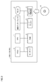
- FIG. 1 is a diagram illustrating an example of a configuration of a watching system.
- FIG. 1 is a block diagram illustrating an outline of a configuration of a watching system.
- FIG. 3 is a block diagram illustrating a hardware configuration of a computer system 300 functioning as a cloud server 150. It is a figure showing an example of the outline of the device composition of watching system 100 using sensor box 119. It is a figure explaining sensor data in a resting state at the time of sleep of a subject acquired by sensor box 119 based on an embodiment. It is a figure explaining sensor data in an awake state at the time of sleep of a subject acquired by sensor box 119 based on an embodiment.
- FIG. 3 is a diagram illustrating power spectrum data based on the embodiment. It is a figure explaining change of power integrated value other than near a peak value according to a modification of an embodiment. It is a figure explaining the judgment of the rest state and the awake state at the time of sleep.
- a respiratory signal is measured as biological information of a target person such as a resident of the facility, and the daily state of the target person can be accurately grasped.
- the measurement is performed in a state where the subject is not conscious of the measurement.
- FIG. 1 is a diagram illustrating an example of the configuration of the watching system 100.
- the watching target is, for example, a resident in each living room provided in the living room area 180 of the facility.
- living rooms 110 and 120 are provided in a living room area 180.
- the living room 110 is assigned to the resident 111.
- the living room 120 is assigned to the resident 121.
- the number of living rooms included in the watching system 100 is two, but the number is not limited to this.
- Network 190 may include both an intranet and the Internet.
- the portable terminal 143 carried by the caregiver 141 and the portable terminal 144 carried by the caregiver 142 can be connected to the network 190 via the access point 140. Further, the sensor box 119, the management server 200, and the access point 140 can communicate with the cloud server 150 via the network 190.
- Each of the living rooms 110 and 120 includes a closet 112, a bed 113, and a toilet 114 as facilities.
- the door of the living room 110 is provided with a door sensor 118 that detects opening and closing of the door.
- a toilet sensor 116 that detects the opening and closing of the toilet 114 is installed on the door of the toilet 114.
- the bed 113 is provided with an odor sensor 117 for detecting the odor of each of the residents 111 and 121.
- each of the residents 111 and 121 can operate the care call slave unit 115, respectively.
- the sensor box 119 has a built-in sensor for detecting the behavior of an object in the living rooms 110 and 120.
- a sensor is a Doppler sensor for detecting the movement of an object.
- a camera is another example.
- the sensor box 119 may include both a Doppler sensor and a camera as sensors.
- FIG. 2 is a block diagram illustrating an outline of a configuration of the watching system 100.
- the sensor box 119 includes a control device 101, a read only memory (ROM) 102, a random access memory (RAM) 103, a communication interface 104, a camera 105, a Doppler sensor 106, a wireless communication device 107, and a storage device. 108.
- the control device 101 controls the sensor box 119.
- the control device 101 is composed of, for example, at least one integrated circuit.
- the integrated circuit is, for example, at least one CPU (Central Processing Unit), MPU (Micro Processing Unit) or another processor, at least one ASIC (Application Specific Integrated Circuit), at least one FPGA (Field Programmable Gate Array), or these. And the like.
- An antenna (not shown) and the like are connected to the communication interface 104.
- the sensor box 119 exchanges data with an external communication device via the antenna.
- External communication devices include, for example, the management server 200, the mobile terminals 143, 144 and other terminals, the access point 140, the cloud server 150, and other communication terminals.
- the camera 105 is a near-infrared camera in one implementation.
- the near-infrared camera includes an IR (Infrared) projector that emits near-infrared light.
- IR Infrared
- camera 105 is a surveillance camera that receives only visible light.
- a 3D sensor or a thermographic camera may be used as camera 105.
- the sensor box 119 and the camera 105 may be configured integrally or may be configured separately.
- the Doppler sensor 106 is, for example, a microwave Doppler sensor, and emits and receives radio waves to detect the behavior (movement) of an object in the living rooms 110 and 120. Thereby, the biological information of the resident 111, 121 of the living room 110, 120 can be detected.
- the Doppler sensor 106 emits microwaves in the 24 GHz band toward the beds 113 of the rooms 110 and 120 and receives reflected waves reflected by the residents 111 and 121. The reflected waves are Doppler shifted by the actions of the residents 111 and 121.
- the Doppler sensor 106 can detect the respiratory state and the heart rate of the residents 111 and 121 from the reflected waves.
- the wireless communication device 107 receives signals from the care call slave device 240, the door sensor 118, the toilet sensor 116, and the odor sensor 117, and transmits the signals to the control device 101.
- the care call slave unit 240 includes a care call button 241. When the button is operated, the care call slave device 240 transmits a signal indicating that the operation has been performed to the wireless communication device 107.
- the door sensor 118, the toilet sensor 116, and the odor sensor 117 transmit the respective detection results to the wireless communication device 107.
- the storage device 108 is, for example, a fixed storage device such as a flash memory or a hard disk, or a recording medium such as an external storage device.
- the storage device 108 stores a program executed by the control device 101 and various data used for executing the program.
- the various data may include the behavior information of the residents 111 and 121.
- At least one of the above-described programs and data is a storage device other than the storage device 108 (for example, a storage area (for example, a cache memory or the like) of the control device 101, a ROM 102,
- the RAM 103 may be stored in an external device (for example, the management server 200 or the mobile terminals 143 and 144).
- the mobile terminals 143 and 144 include a control device 221, a ROM 222, a RAM 223, a communication interface 224, a display 226, a storage device 228, and an input device 229.
- the mobile terminals 143 and 144 are realized as, for example, a smartphone, a tablet terminal, a wristwatch-type terminal, or another wearable device.
- the control device 221 controls the mobile terminals 143 and 144.
- the control device 221 is configured by, for example, at least one integrated circuit.
- the integrated circuit includes, for example, at least one CPU, at least one ASIC, at least one FPGA, or a combination thereof.
- the mobile terminals 143 and 144 exchange data with an external communication device via the antenna and the access point 140.
- the external communication device includes, for example, the sensor box 119, the management server 200, and the like.
- the display 226 is realized by, for example, a liquid crystal display, an organic EL (Electroluminescence) display, or the like.
- the input device 229 is realized by, for example, a touch sensor provided on the display 226. The touch sensor receives a touch operation on the mobile terminals 143 and 144, and outputs a signal corresponding to the touch operation to the control device 221.
- the storage device 228 is realized by, for example, a flash memory, a hard disk or another fixed storage device, or a removable data recording medium.
- the management server 200 includes an analysis unit 202 and a determination unit 204.
- the analysis unit 202 and the determination unit 204 are realized by the CPU executing a program stored in the memory.
- the analysis unit 202 reads the sensor data stored in the hard disk 5 of the cloud server 150 and acquires the spectrum data of the respiration signal.
- the determination unit 204 determines the state or the like of the subject based on the spectrum data of the respiratory signal.
- FIG. 3 is a block diagram illustrating a hardware configuration of computer system 300 functioning as cloud server 150.
- the computer system 300 includes, as main components, a CPU 1 for executing a program, a mouse 2 and a keyboard 3 for receiving an instruction input by a user of the computer system 300, and data generated by executing the program by the CPU 1 or a mouse 2.
- a RAM 4 for volatilely storing data input via the keyboard 3
- a hard disk 5 for nonvolatilely storing data
- an optical disk drive 6 a communication interface (I / F) 7, and a monitor 8 Including.
- Each component is mutually connected by a data bus.
- the optical disk drive 6 is loaded with a CD-ROM 9 and other optical disks.
- the processing in the computer system 300 is realized by each hardware and software executed by the CPU 1.
- Such software may be stored in the hard disk 5 in advance.
- the software is stored on a CD-ROM 9 or another recording medium and is distributed as a computer program.
- the software may be provided as a downloadable application program by an information provider connected to the so-called Internet.
- Such software is temporarily stored in the hard disk 5 after being read from the recording medium by the optical disk drive 6 or another reading device, or downloaded via the communication interface 7.
- the software is read from the hard disk 5 by the CPU 1 and stored in the RAM 4 in the form of an executable program.
- CPU 1 executes the program.
- Each component constituting the computer system 300 shown in FIG. 3 is a general one. Therefore, it can be said that one of the essential parts of the technical idea according to the present disclosure is software stored in the RAM 4, the hard disk 5, the CD-ROM 9, or another recording medium, or software downloadable via a network.
- the storage medium may include a non-transitory, computer-readable data storage medium. Since the operation of each piece of hardware of computer system 300 is well known, detailed description will not be repeated.
- the recording medium is not limited to a CD-ROM, FD (Flexible Disk), or hard disk, but may be a magnetic tape, a cassette tape, an optical disk (MO (Magnetic Optical Disc) / MD (Mini Disc) / DVD (Digital Versatile Disc)). , IC (Integrated Circuit) card (including memory card), optical card, mask ROM, EPROM (Electronically Programmable Read-Only Memory), EEPROM (Electronically Erasable Programmable Read-Only Memory), and fixing of semiconductor memory such as flash ROM It may be a medium that carries the program.
- IC Integrated Circuit
- the program mentioned here includes not only a program directly executable by the CPU but also a program in a source program format, a compressed program, an encrypted program, and the like.
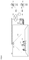
- FIG. 4 is a diagram illustrating an example of a schematic device configuration of the watching system 100 using the sensor box 119.
- the watching system 100 is used for watching the residents 111 and 121 who are the monitoring targets (monitoring targets) and other residents. As shown in FIG. 4, a sensor box 119 is attached to the ceiling of the living room 110. Sensor boxes 119 are similarly attached to other rooms.
- the range 410 represents the detection range of the sensor box 119.
- the Doppler sensor detects a person's behavior occurring in the area 410.
- the sensor box 119 has a camera as a sensor, the camera captures an image in the range 410.
- the sensor box 119 is installed in, for example, a nursing facility, a medical facility, a house, or the like. In the example of FIG. 4, the sensor box 119 is attached to the ceiling, and the resident 111 and the bed 113 are photographed from the ceiling. The place where the sensor box 119 is attached is not limited to the ceiling, and may be attached to the side wall of the living room 110.
- the watching system 100 detects a danger occurring to the resident 111 based on a series of images (that is, videos) obtained from the camera 105.
- the detectable danger includes a fall of the resident 111 and a state where the resident 111 is at a danger location (for example, a bed fence).
- the monitoring system 100 When the monitoring system 100 detects that the resident 111 is in danger, the monitoring system 100 notifies the caregivers 141, 143, and the like of that. As an example of the notification method, the watching system 100 notifies the danger of the resident 111 to the portable terminals 143 and 144 of the caregivers 141 and 142. Upon receiving the notification, the mobile terminals 143 and 144 notify the caregivers 141 and 142 of the danger of the resident 111 by a message, voice, vibration, or the like. Thus, the caregivers 141 and 142 can immediately recognize that the resident 111 is in danger, and can rush to the resident 111 quickly.
- FIG. 4 shows an example in which the watching system 100 includes one sensor box 119, but the watching system 100 may include a plurality of sensor boxes 119.
- FIG. 4 illustrates an example in which the watching system 100 includes a plurality of mobile terminals 143 and 144. However, the watching system 100 can be realized by a single mobile terminal.
- the communication interface 104 of the sensor box 119 in this example transmits the sensor data acquired by the Doppler sensor 106 to the cloud server 150.
- the cloud server 150 stores the data on the hard disk 5 as an example.
- the management server 200 reads out the sensor data stored in the hard disk 5 of the cloud server 150 and executes a predetermined process. In this example, the state of the subject is determined.
- the subject is awake or at rest during sleep, and whether the subject is in the room or absent.
- FIG. 5 is a diagram illustrating sensor data in a resting state during sleep of the subject acquired by the sensor box 119 based on the embodiment.
- the reflected wave of the microwave by the Doppler sensor is detected.
- the subject is in a resting state while sleeping on the bed, there are few movements other than the breathing movement. Therefore, a signal having a small amplitude and a constant period of the reflected wave is detected in accordance with the movement of the breathing motion.
- FIG. 6 is a diagram illustrating sensor data in the awake state during sleep of the subject acquired by the sensor box 119 based on the embodiment.
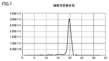
- FIG. 7 is a diagram illustrating the spectrum data of the sensor data when the user is in a resting state during sleep based on the embodiment.
- the analysis unit 202 of the management server 200 reads out the sensor data of FIG. 5 stored in the hard disk 5 of the cloud server 150 and acquires the spectrum data of the respiratory signal.
- the horizontal axis represents the respiratory rate (times / minute), and the vertical axis represents the signal intensity. If the user is in a resting state during sleep, a substantially constant cycle is detected in accordance with the breathing motion. In this example, a case where the peak value of the sensor data is detected at the position of 19 times / minute is shown.
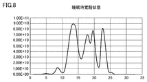
- FIG. 8 is a diagram illustrating the spectrum data of the sensor data when the user is in the awake state during sleep based on the embodiment.
- the analysis unit 202 of the management server 200 reads out and analyzes the sensor data of FIG. 6 stored in the hard disk 5 of the cloud server 150, and acquires the spectrum data of the respiratory signal.
- the horizontal axis indicates the respiratory rate (times / minute), and the vertical axis indicates the signal intensity.
- a plurality of peak waveforms are detected in accordance with other operations in addition to the respiratory operation.
- the waveform of the respiration rate (times / minute) corresponding to the highest peak value is 13 times / minute.
- the signal strength differs between the resting state during sleep and the awake state. Between the resting state during sleep and the awake state, the signal strength is larger in the rest state during sleep than in the awake state. This is because the maximum value differs depending on the distance between the subject and the sensor box 119 and the direction of movement. Therefore, the signal strength in the awake state is smaller than that in the rest state during sleep, so that it may be difficult to determine the awake state.
- a process of normalizing the maximum value of the peak signal intensity to 1 every predetermined period is executed.
- the maximum value of the peak value is normalized to 1 during the period in which the signal strength is different, and it becomes easy to compare the waveform shapes in the resting state and the awake state.
- FIG. 9 is a diagram illustrating a method for determining a resting state during sleep based on the embodiment. This is mainly processing in the determination unit 204.
- the vertical axis indicates a state in which the maximum value of the peak value of the signal strength is normalized to 1. Then, the waveform line width near the peak value of the spectrum data is detected, and it is determined whether the waveform line width is equal to or smaller than a predetermined value. When the waveform line width is narrower than the predetermined value as in this example, it can be determined that the sleeping state is at rest.
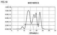
- FIG. 10 is a diagram illustrating a method for determining the awake state during sleep based on the embodiment.
- the vertical axis indicates a state where the maximum value of the peak value of the signal strength is normalized to 1.
- the waveform line width near the peak value of the spectrum data is detected, and it is determined whether the waveform line width is equal to or smaller than a predetermined value. If the waveform line width is wider than a predetermined value as in this example, it can be determined that the user is in the awake state during sleep.
- the present invention is not limited to this, and the detection may be performed at another position. Further, a predetermined value serving as a threshold may be changed at the position of the strength of the signal to be detected.
- the method makes a comparison and determination in a state where the peak value of the signal strength is normalized to 1, thereby providing a highly accurate subject. Can be determined.
- FIG. 11 is a diagram illustrating power spectrum data based on the embodiment. 11, the determination unit 204 of the management server 200 generates power spectrum data based on the spectrum data of the sensor data.
- the power in a predetermined range including the peak value of the sensor data is the sum of the power in a predetermined range including the peak value of the sensor data.
- a peak value of 19 times / minute is detected as an example of the spectrum data of the sensor data
- the power in the range of four times (15 to 23 times / minute) before and after as the predetermined range is obtained. Is calculated. In this case, for example, 5.8E + 11 is calculated.
- the determination unit 204 determines that the power spectrum data greater than the threshold is the presence of the subject (occupied in the room) and determines that the power spectrum data is lower than the threshold.
- the power spectrum data can be determined as the absence (absence) of the subject.
- the subject exists in the time zone where the power spectrum data is equal to or more than 1E + 10 as a threshold, and otherwise the subject is absent, so the data in the time zone (absence) is ignored. Is possible.
- the determination is made based on a comparison between the power in a predetermined range including the peak value of the spectrum data of the sensor data and the power in a region other than the predetermined range.
- the power integrated value in the vicinity of the peak value in the resting state during sleep (a range of four times before and after 15 to 23 times / minute) is 1.862.
- the total power integrated value (0 to 35 times / minute) is calculated, it is 1.956.
- the power integrated value near the peak value is subtracted from the total power integrated value.
- the power integrated value calculated near the peak value of the awake state during sleep (range of 4 times before and after 9 to 17 times / minute) is 4.382.
- the total power integrated value (0 to 35 times / minute) is calculated, it is 8.922.
- the power integrated value near the peak value is subtracted from the total power integrated value.
- FIG. 12 is a diagram illustrating a change in the integrated power value other than near the peak value according to the modification of the embodiment.
- the determination unit 204 generates data of the fluctuation of the power integrated value according to the above method.
- the determination unit 204 sets the threshold value to 1 in this example, and determines whether the user is in the awake state or in the resting state during sleep based on whether or not the average value is the threshold value (“1”). Is determined.
- the sleep state is determined. Therefore, the determination is made during the period when the subject is in the room, and is not determined when the subject is absent.
- FIG. 12 shows, as an example, a case where the user is present in the room and a case where the user is absent, and determines the sleep state when the user is present. This is mainly processing in the determination unit 204.
- FIG. 13 is a diagram illustrating determination of a resting state and an awake state during sleep. Referring to FIG. 13, it is determined whether or not the power integrated value in FIG. 12 is equal to or smaller than a threshold ("1"). If it is less than or equal to the threshold value ("1"), it is determined that it is in a resting state, and if it exceeds the threshold value ("1"), it is determined that it is in an awake state.
- a threshold a threshold
- ⁇ It is possible to grasp the state of the subject during sleep based on the determination result. That is, if the period of the resting state during sleep is long, it is possible to determine that the sleeping state is good. For example, it is possible to determine whether or not a good sleep state is based on whether or not a rest state during sleep for a predetermined period or more is secured.
- a sleep state is bad based on whether or not a wakeful state during sleep for a predetermined period or more is pending.
- the ratio between the power integrated value near the peak value and the power integrated value other than near the peak value may be calculated. In the case of a resting state during sleep, the ratio becomes 0 because the power integrated value other than near the peak value becomes small. On the other hand, in the awake state during sleep, the ratio approaches 1 because the power integrated value other than near the peak value increases.
- a resting state or awake state during sleep may be determined by comparison with a predetermined threshold value.
- the signal level of the biological information of the subject is determined based on a comparison between the power of the predetermined range including the peak value of the spectrum data and the power of the region other than the predetermined range. It is possible to grasp the state of the subject with high accuracy even in a low case.
- the management server 200 includes the analysis unit 202 and the determination unit 204 has been described.
- the present invention is not particularly limited to this, and a single state monitoring device may be provided by providing the sensor box 119 with the function. Of course it is possible.
- This technology is applicable to information obtained in hospitals, nursing homes, nursing homes and other facilities.
- 100 system 101,221 control device, 106 Doppler sensor, 107 wireless communication device, 108 storage device, 109 door, 110,120 living room, 111, 121, 910, 920, 930, 950 resident, 112 closet, 113 bed, 114 toilet, 115 care call handset, 116 toilet sensor, 117 sensor, 118 door sensor, 119 sensor box, 130 management center, 140 access point, 141, 142 caregiver, 143, 144 mobile terminal, 150 cloud server, 190 network, 200 management server, 226 display, 229 input device, 241 care call button, 290 vital sensor, 300 computer system.
Landscapes
- Health & Medical Sciences (AREA)
- Life Sciences & Earth Sciences (AREA)
- Physics & Mathematics (AREA)
- Engineering & Computer Science (AREA)
- Animal Behavior & Ethology (AREA)
- Public Health (AREA)
- Veterinary Medicine (AREA)
- General Health & Medical Sciences (AREA)
- Surgery (AREA)
- Molecular Biology (AREA)
- Medical Informatics (AREA)
- Heart & Thoracic Surgery (AREA)
- Biomedical Technology (AREA)
- Pathology (AREA)
- Biophysics (AREA)
- Business, Economics & Management (AREA)
- Oral & Maxillofacial Surgery (AREA)
- Dentistry (AREA)
- Emergency Management (AREA)
- Physiology (AREA)
- General Physics & Mathematics (AREA)
- Psychiatry (AREA)
- Developmental Disabilities (AREA)
- Educational Technology (AREA)
- Child & Adolescent Psychology (AREA)
- Hospice & Palliative Care (AREA)
- Psychology (AREA)
- Social Psychology (AREA)
- Measurement Of The Respiration, Hearing Ability, Form, And Blood Characteristics Of Living Organisms (AREA)
- Measurement And Recording Of Electrical Phenomena And Electrical Characteristics Of The Living Body (AREA)
Abstract
精度の高い被検者の状態の判定が可能な状態監視装置を提供する。 状態監視装置は、被検者にマイクロ波を照射して、被検者から反射された反射波を検出する検出部と、検出部で検出した反射波を解析して呼吸信号のスペクトルデータを取得する解析部と、呼吸信号のスペクトルデータに基づいて被検者の睡眠時の状態を判定する判定部とを備える。
Description
本開示は、居住者の安否を監視する状態監視装置に関する。
居住者を見守る技術が知られている。例えば、特開2017-174012号公報(特許文献1)には、IT(Information Technology)を利用して高齢者等の状態を監視する見守りシステムが提案されている。被検者にトラブル等が生じた場合に、速やかに介護士、看護師等が介助等を行うことが可能になる。被検者の状態を画面にリアルタイムで表示し、通常とは異なる事象、すなわちイベントが発生している被検者の状態を表示する情報処理装置が開示されている。
また、特許第5682504号公報(特許文献2)においては、被検者の生体情報を収集して被検者の安否を監視する監視装置において、被検者にマイクロ波を照射し、そのドップラシフトした反射波から、被検者の体動と呼吸とを検出し、所定時間内の体動数と呼吸数とから被検者の安否を監視する方式が開示されている。
一方で、上記被検者の安否を監視する方式において、被検者の生体情報の信号レベルが低い場合には精度の高い被検者の状態の判定ができないという課題があった。
本開示は上述のような背景に鑑みてなされたものであって、ある局面における目的は、精度の高い被検者の状態の判定が可能な状態監視装置および状態監視方法を提供することである。
ある実施の形態に従うと、状態監視装置は、被検者にマイクロ波を照射して、被検者から反射された反射波を検出する検出部と、検出部で検出した反射波を解析して呼吸信号のスペクトルデータを取得する解析部と、呼吸信号のスペクトルデータに基づいて被検者の睡眠時の状態を判定する判定部とを備える。
好ましくは、判定部は、呼吸信号のスペクトルデータの波形線幅が所定値よりも大きい場合に睡眠時の覚醒状態と判定し、呼吸信号のスペクトルデータの波形線幅が所定値以下の場合に睡眠時の安静状態と判定する。
好ましくは、呼吸信号のスペクトルデータは、所定期間毎にピーク値を有する。判定部は、所定期間毎のピーク値の最大値を所定値に規格化し、呼吸信号のスペクトルデータの波形線幅が所定値よりも大きい場合に睡眠時の覚醒状態と判定し、呼吸信号のスペクトルデータの波形線幅が所定値以下の場合に睡眠時の安静状態と判定する。
好ましくは、判定部は、呼吸信号のパワースペクトルデータを生成し、パワースペクトラムデータが所定値以上であるか否かを判定し、パワースペクトラムデータが所定値以上である場合には被検者の在室状態として判定し、パワースペクトラムデータが所定値未満である場合には被検者の不在状態として判定する。
好ましくは、呼吸信号のスペクトルデータは、ピーク値を示す周波数領域と、それ以外の周波数領域とに分割され、判定部は、ピーク値を示す周波数領域のスペクトルデータのパワー積算値と、それ以外の周波数領域のスペクトルデータのパワー積算値との比または差分が所定値以上である場合には睡眠時の覚醒状態と判定し、比または差分が所定値未満である場合には、睡眠時の安静状態と判定する。
ある実施の形態に従うと、状態監視方法は、被検者にマイクロ波を照射して、被検者から反射された反射波を検出するステップと、検出した反射波を解析して呼吸信号のスペクトルデータを取得するステップと、呼吸信号のスペクトルデータに基づいて被検者の睡眠時の状態を判定するステップとを備える。
好ましくは、被験者の睡眠時の状態を判定するステップは、呼吸信号のスペクトルデータの波形線幅が所定値よりも大きい場合に睡眠時の覚醒状態と判定し、呼吸信号のスペクトルデータの波形線幅が所定値以下の場合に睡眠時の安静状態と判定する。
好ましくは、被験者の睡眠時の状態を判定するステップは、呼吸信号のスペクトルデータは、所定期間毎にピーク値を有する。所定期間毎のピーク値の最大値を所定値に規格化し、呼吸信号のスペクトルデータの波形線幅が所定値よりも大きい場合に睡眠時の覚醒状態と判定し、呼吸信号のスペクトルデータの波形線幅が所定値以下の場合に睡眠時の安静状態と判定する。
好ましくは、呼吸信号のスペクトルデータは、ピーク値を示す周波数領域と、それ以外の周波数領域とに分割される。被験者の睡眠時の状態を判定するステップは、ピーク値を示す周波数領域のスペクトルデータのパワー積算値と、それ以外の周波数領域のスペクトルデータのパワー積算値との比または差分が所定値以上である場合には睡眠時の覚醒状態と判定し、比または差分が所定値未満である場合には、睡眠時の安静状態と判定する。
ある局面において、精度の高い被検者の状態の判定が可能である。
この発明の上記および他の目的、特徴、局面および利点は、添付の図面と関連して理解されるこの発明に関する次の詳細な説明から明らかとなるであろう。
この発明の上記および他の目的、特徴、局面および利点は、添付の図面と関連して理解されるこの発明に関する次の詳細な説明から明らかとなるであろう。
以下、図面を参照しつつ、本開示に係る技術思想の実施の形態について説明する。以下の説明では、同一の部品には同一の符号を付してある。それらの名称および機能も同じである。したがって、それらについての詳細な説明は繰り返さない。
[技術思想]
まず、本明細書に開示にされる技術思想の概要について説明する。ある局面において、施設の入居者等の対象者の生体情報として呼吸信号が測定され、対象者の日頃の状態を正確に把握することができる。測定は、対象者が測定していることを意識していない状態で行なわれる。
まず、本明細書に開示にされる技術思想の概要について説明する。ある局面において、施設の入居者等の対象者の生体情報として呼吸信号が測定され、対象者の日頃の状態を正確に把握することができる。測定は、対象者が測定していることを意識していない状態で行なわれる。
[見守りシステム(状態監視装置)の構成]
図1は、見守りシステム100の構成の一例を示す図である。見守り対象は、例えば、施設の居室領域180に設けられた各居室内の入居者である。図1の見守りシステム100では、居室領域180に、居室110,120が設けられている。居室110は、入居者111に割り当てられている。居室120は、入居者121に割り当てられている。図1の例では、見守りシステム100に含まれる居室の数は2であるが、当該数はこれに限定されない。
図1は、見守りシステム100の構成の一例を示す図である。見守り対象は、例えば、施設の居室領域180に設けられた各居室内の入居者である。図1の見守りシステム100では、居室領域180に、居室110,120が設けられている。居室110は、入居者111に割り当てられている。居室120は、入居者121に割り当てられている。図1の例では、見守りシステム100に含まれる居室の数は2であるが、当該数はこれに限定されない。
見守りシステム100では、居室110,120にそれぞれ設置されたセンサーボックス119と、管理センター130に設置された管理サーバー200と、アクセスポイント140とが、ネットワーク190を介して接続される。ネットワーク190は、イントラネットおよびインターネットのいずれをも含み得る。
見守りシステム100では、介護者141が携帯する携帯端末143、および、介護者142が携帯する携帯端末144は、アクセスポイント140を介してネットワーク190に接続可能である。さらに、センサーボックス119、管理サーバー200、および、アクセスポイント140は、ネットワーク190を介して、クラウドサーバー150と通信可能である。
居室110,120は、それぞれ、設備として、タンス112、ベッド113、および、トイレ114を含む。居室110のドアには、当該ドアの開閉を検出するドアセンサー118が設置されている。トイレ114のドアには、トイレ114の開閉を検出するトイレセンサー116が設置されている。ベッド113には、各入居者111,121の臭いを検出する臭いセンサー117が設置されている。居室110,120では、各入居者111,121は、それぞれ、ケアコール子機115を操作することができる。
センサーボックス119は、居室110,120内の物体の挙動を検出するためのセンサーを内蔵している。センサーの一例は、物体の動作を検出するためのドップラーセンサーである。他の例は、カメラである。センサーボックス119は、センサーとしてドップラーセンサーとカメラの双方を含んでもよい。
図2を参照して、見守りシステム100の構成要素について説明する。図2は、見守りシステム100の構成の概要を示すブロック図である。
[センサーボックス119]
センサーボックス119は、制御装置101と、ROM(Read Only Memory)102と、RAM(Random Access Memory)103と、通信インターフェイス104と、カメラ105と、ドップラーセンサー106と、無線通信装置107と、記憶装置108とを備える。
センサーボックス119は、制御装置101と、ROM(Read Only Memory)102と、RAM(Random Access Memory)103と、通信インターフェイス104と、カメラ105と、ドップラーセンサー106と、無線通信装置107と、記憶装置108とを備える。
制御装置101は、センサーボックス119を制御する。制御装置101は、たとえば、少なくとも1つの集積回路によって構成される。集積回路は、たとえば、少なくとも1つのCPU(Central Processing Unit)、MPU(Micro Processing Unit)その他のプロセッサー、少なくとも1つのASIC(Application Specific Integrated Circuit)、少なくとも1つのFPGA(Field Programmable Gate Array)、またはこれらの組み合わせなどによって構成される。
通信インターフェイス104には、アンテナ(図示しない)などが接続される。センサーボックス119は、当該アンテナを介して、外部の通信機器との間でデータをやり取りする。外部の通信機器は、たとえば、管理サーバー200、携帯端末143,144その他の端末、アクセスポイント140、クラウドサーバー150、その他の通信端末などを含む。
カメラ105は、一実現例では、近赤外カメラである。近赤外カメラは、近赤外光を投光するIR(Infrared)投光器を含む。近赤外カメラが用いられることにより、夜間でも居室110,120の内部を表わす画像が撮影され得る。他の実現例では、カメラ105は、可視光のみを受光する監視カメラである。さらに他の実現例では、カメラ105として、3Dセンサやサーモグラフィーカメラが用いられてもよい。センサーボックス119およびカメラ105は、一体として構成されてもよいし、別体で構成されてもよい。
ドップラーセンサー106は、たとえばマイクロ波ドップラーセンサーであり、電波を放射及び受信して、居室110,120内の物体の挙動(動作)を検出する。これにより、居室110,120の入居者111,121の生体情報が検出され得る。一例では、ドップラーセンサー106は、24GHz帯のマイクロ波を各居室110,120のベッド113に向けて放射し、入居者111,121で反射した反射波を受信する。反射波は、入居者111,121の動作により、ドップラーシフトしている。ドップラーセンサー106は、当該反射波から、入居者111,121の呼吸状態や心拍数を検出し得る。
無線通信装置107は、ケアコール子機240、ドアセンサー118、トイレセンサー116、臭いセンサー117からの信号を受信し、当該信号を制御装置101へ送信する。たとえば、ケアコール子機240は、ケアコールボタン241を備える。当該ボタンが操作されると、ケアコール子機240は、当該操作があったことを示す信号を無線通信装置107へ送信する。ドアセンサー118、トイレセンサー116、臭いセンサー117は、それぞれの検出結果を無線通信装置107へ送信する。
記憶装置108は、たとえば、フラッシュメモリーまたはハードディスク等の固定記憶装置、あるいは、外付けの記憶装置などの記録媒体である。記憶装置108は、制御装置101によって実行されるプログラム、および、当該プログラムの実行に利用される各種のデータを格納する。各種のデータは、入居者111,121の行動情報を含んでいてもよい。
上記のプログラムおよびデータのうち少なくとも一方は、制御装置101がアクセス可能な記憶装置であれば、記憶装置108以外の記憶装置(たとえば、制御装置101の記憶領域(たとえば、キャッシュメモリーなど)、ROM102、RAM103、外部機器(たとえば、管理サーバー200や携帯端末143,144等)に格納されていてもよい。
[携帯端末143,144]
携帯端末143,144は、制御装置221と、ROM222と、RAM223と、通信インターフェイス224と、ディスプレイ226と、記憶装置228と、入力デバイス229とを含む。ある局面において、携帯端末143,144は、例えば、スマートフォン、タブレット端末、腕時計型端末その他のウェアラブル装置等として実現される。
携帯端末143,144は、制御装置221と、ROM222と、RAM223と、通信インターフェイス224と、ディスプレイ226と、記憶装置228と、入力デバイス229とを含む。ある局面において、携帯端末143,144は、例えば、スマートフォン、タブレット端末、腕時計型端末その他のウェアラブル装置等として実現される。
制御装置221は、携帯端末143,144を制御する。制御装置221は、たとえば、少なくとも1つの集積回路によって構成される。集積回路は、たとえば、少なくとも1つのCPU、少なくとも1つのASIC、少なくとも1つのFPGA、またはそれらの組み合わせなどによって構成される。
通信インターフェイス224には、アンテナ(図示しない)などが接続される。携帯端末143,144は、当該アンテナおよびアクセスポイント140を介して、外部の通信機器との間でデータをやり取りする。外部の通信機器は、たとえば、センサーボックス119、管理サーバー200などを含む。
ディスプレイ226は、たとえば液晶ディスプレイ、有機EL(Electro luminescence)ディスプレイ等によって実現される。入力デバイス229は、たとえばディスプレイ226に設けられたタッチセンサーによって実現される。当該タッチセンサーは、携帯端末143,144に対するタッチ操作を受け付け、当該タッチ操作に応じた信号を制御装置221へ出力する。
記憶装置228は、たとえば、フラッシュメモリー、ハードディスクその他の固定記憶装置、あるいは、着脱可能なデータ記録媒体等により実現される。
[管理サーバー200]
管理サーバー200は、解析部202および判定部204を含む。
管理サーバー200は、解析部202および判定部204を含む。
解析部202および判定部204は、CPUがメモリに格納されているプログラムを実行することにより実現する。解析部202は、クラウドサーバー150のハードディスク5に格納されているセンサデータを読み出して呼吸信号のスペクトルデータを取得する。
判定部204は、呼吸信号のスペクトラムデータに基づいて被検者の状態等を判定する。
[クラウドサーバーの構成]
図3を参照して、クラウドサーバー150の構成について説明する。図3は、クラウドサーバー150として機能するコンピューターシステム300のハードウェア構成を表わすブロック図である。
図3を参照して、クラウドサーバー150の構成について説明する。図3は、クラウドサーバー150として機能するコンピューターシステム300のハードウェア構成を表わすブロック図である。
コンピューターシステム300は、主たる構成要素として、プログラムを実行するCPU1と、コンピューターシステム300の使用者による指示の入力を受けるマウス2およびキーボード3と、CPU1によるプログラムの実行により生成されたデータ、又はマウス2若しくはキーボード3を介して入力されたデータを揮発的に格納するRAM4と、データを不揮発的に格納するハードディスク5と、光ディスク駆動装置6と、通信インターフェイス(I/F)7と、モニター8とを含む。各構成要素は、相互にデータバスによって接続されている。光ディスク駆動装置6には、CD-ROM9その他の光ディスクが装着される。
コンピューターシステム300における処理は、各ハードウェアおよびCPU1により実行されるソフトウェアによって実現される。このようなソフトウェアは、ハードディスク5に予め記憶されている場合がある。また、ソフトウェアは、CD-ROM9その他の記録媒体に格納されて、コンピュータープログラムとして流通している場合もある。あるいは、ソフトウェアは、いわゆるインターネットに接続されている情報提供事業者によってダウンロード可能なアプリケーションプログラムとして提供される場合もある。このようなソフトウェアは、光ディスク駆動装置6その他の読取装置によりその記録媒体から読み取られて、あるいは、通信インターフェイス7を介してダウンロードされた後、ハードディスク5に一旦格納される。そのソフトウェアは、CPU1によってハードディスク5から読み出され、RAM4に実行可能なプログラムの形式で格納される。CPU1は、そのプログラムを実行する。
図3に示されるコンピューターシステム300を構成する各構成要素は、一般的なものである。したがって、本開示に係る技術思想の本質的な部分の一つは、RAM4、ハードディスク5、CD-ROM9その他の記録媒体に格納されたソフトウェア、あるいはネットワークを介してダウンロード可能なソフトウェアであるともいえる。記録媒体は、一時的でない、コンピューター読取可能なデータ記録媒体を含み得る。なお、コンピューターシステム300の各ハードウェアの動作は周知であるので、詳細な説明は繰り返さない。
なお、記録媒体としては、CD-ROM、FD(Flexible Disk)、ハードディスクに限られず、磁気テープ、カセットテープ、光ディスク(MO(Magnetic Optical Disc)/MD(Mini Disc)/DVD(Digital Versatile Disc))、IC(Integrated Circuit)カード(メモリーカードを含む)、光カード、マスクROM、EPROM(Electronically Programmable Read-Only Memory)、EEPROM(Electronically Erasable Programmable Read-Only Memory)、フラッシュROMなどの半導体メモリー等の固定的にプログラムを担持する媒体でもよい。
ここでいうプログラムとは、CPUにより直接実行可能なプログラムだけでなく、ソースプログラム形式のプログラム、圧縮処理されたプログラム、暗号化されたプログラム等を含む。
[見守りシステム100の装置構成]
図4を参照して、見守りシステム100を用いた見守りについて説明する。図4は、センサーボックス119を用いた見守りシステム100の装置構成の概略の一例を示す図である。
図4を参照して、見守りシステム100を用いた見守りについて説明する。図4は、センサーボックス119を用いた見守りシステム100の装置構成の概略の一例を示す図である。
見守りシステム100は、見守り対象者(監視対象者)である入居者111,121その他の入居者を見守るために利用される。図4に示されるように、居室110の天井には、センサーボックス119が取り付けられている。他の居室にも同様にセンサーボックス119が取り付けられている。
範囲410は、センサーボックス119による検出範囲を表わす。センサーボックス119が前述のドップラーセンサーを有する場合、当該ドップラーセンサーは、範囲410内で生じた人の挙動を検出する。センサーボックス119がセンサーとしてカメラを有する場合、当該カメラは、範囲410内の画像を撮影する。
センサーボックス119は、たとえば、介護施設、医療施設、宅内などに設置される。図4の例では、センサーボックス119は、天井に取り付けられており、入居者111およびベッド113を天井から撮影している。センサーボックス119の取り付け場所は天井に限られず、居室110の側壁に取り付けられてもよい。
見守りシステム100は、カメラ105から得られた一連の画像(すなわち、映像)に基づいて入居者111に生じている危険を検知する。一例として、検知可能な危険は、入居者111の転倒や、危険個所(たとえば、ベッドの柵など)に入居者111がいる状態などを含む。
見守りシステム100は、入居者111に危険が生じていることを検知した場合に、そのことを介護者141,143等に報知する。報知方法の一例として、見守りシステム100は、入居者111の危険を介護者141,142の携帯端末143,144に通知する。携帯端末143,144は、当該通知を受信すると、入居者111の危険をメッセージ、音声、振動等で介護者141,142に報知する。これにより、介護者141,142は、入居者111に危険が生じていることを即座に把握でき、入居者111の元に素早く駆け付けることができる。
なお、図4には、見守りシステム100が1つのセンサーボックス119を備えている例が示されているが、見守りシステム100は、複数のセンサーボックス119を備えてもよい。また、図4には、見守りシステム100が複数の携帯端末143,144を備えている例が示されているが、見守りシステム100は、一つの携帯端末でも実現され得る。
そして、本例におけるセンサーボックス119の通信インターフェイス104は、ドップラーセンサー106で取得したセンサデータをクラウドサーバー150に送信する。
クラウドサーバー150は、一例としてハードディスク5に格納する。
管理サーバー200は、クラウドサーバー150のハードディスク5に格納されているセンサデータを読み出して所定の処理を実行する。本例においては、被検者の状態を判定する。
管理サーバー200は、クラウドサーバー150のハードディスク5に格納されているセンサデータを読み出して所定の処理を実行する。本例においては、被検者の状態を判定する。
具体的には、被検者は睡眠時に覚醒状態あるいは安静状態か、また、被検者は在室しているか不在であるかを判定する。
管理サーバー200は、必要に応じて被検者の状態を介護者に通知する。
[センサデータ]
図5は、実施形態に基づくセンサーボックス119で取得される被検者の睡眠時の安静状態におけるセンサデータについて説明する図である。
[センサデータ]
図5は、実施形態に基づくセンサーボックス119で取得される被検者の睡眠時の安静状態におけるセンサデータについて説明する図である。
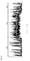
図5に示されるように、ドップラーセンサーによるマイクロ波の反射波が検出される。例えば、被検者がベッドで睡眠時に安静状態である場合には、呼吸動作以外の動きが少ない。したがって、呼吸動作の動きに合わせた反射波が一定の周期で振幅の小さい信号が検出される。
図6は、実施形態に基づくセンサーボックス119で取得される被検者の睡眠時の覚醒状態におけるセンサデータについて説明する図である。
例えば、被検者がベッドで睡眠時に覚醒状態である場合には、呼吸動作以外の動きが大きい。したがって、寝返り等、呼吸動作以外の動きに合わせた反射波が大きく、被検者の動作により信号の波形に大きな振幅が生じる。
図7は、実施形態に基づく睡眠時に安静状態である場合のセンサデータのスペクトルデータについて説明する図である。
図7において、管理サーバー200の解析部202は、クラウドサーバー150のハードディスク5に格納されている上記図5のセンサデータを読み出して、当該呼吸信号のスペクトルデータを取得する。
横軸は呼吸数(回/分)であり、縦軸は、信号の強さを示す。
睡眠時に安静状態である場合には、呼吸動作に合わせてほぼ一定の周期が検出される。本例においては、19回/分の位置でセンサデータのピーク値が検出された場合が示されている。
睡眠時に安静状態である場合には、呼吸動作に合わせてほぼ一定の周期が検出される。本例においては、19回/分の位置でセンサデータのピーク値が検出された場合が示されている。
図8は、実施形態に基づく睡眠時に覚醒状態である場合のセンサデータのスペクトルデータについて説明する図である。
図8において、管理サーバー200の解析部202は、クラウドサーバー150のハードディスク5に格納されている上記図6のセンサデータを読み出して、解析し、当該呼吸信号のスペクトルデータを取得する。
横軸は呼吸数(回/分)であり、縦軸は信号の強さを示す。
睡眠時に覚醒状態である場合には、呼吸動作以外に、他の動作に合わせて複数のピーク波形が検出される。最も高いピーク値に対応する呼吸数(回/分)は、13回/分の波形が示されている。
睡眠時に覚醒状態である場合には、呼吸動作以外に、他の動作に合わせて複数のピーク波形が検出される。最も高いピーク値に対応する呼吸数(回/分)は、13回/分の波形が示されている。
図7および図8に示されるように、睡眠時の安静状態と覚醒状態とでは信号の強さが異なる。睡眠時の安静状態と覚醒状態とでは、睡眠時の安静状態の方が覚醒状態よりも信号の強さは大きい。これは、被験者とセンサーボックス119との距離や動きの向きによって最大値が異なるからである。したがって、睡眠時の安静状態と比べて覚醒状態の信号の強さが小さくなるため覚醒状態の判定が難しい可能性がある。
実施形態においては、所定期間毎にピーク値の信号の強さの最大値を1に規格化する処理を実行する。これにより信号の強さが異なる期間においてピーク値の最大値が1に規格化されて安静状態および覚醒状態の波形形状を比較し易くなる。
図9は、実施形態に基づく睡眠時の安静状態を判定する方式を説明する図である。主に判定部204における処理である。
図9に示されるように、縦軸は、信号の強さのピーク値の最大値を1に規格化した状態を示している。そして、スペクトルデータのピーク値付近の波形線幅を検出し、波形線幅が所定値以下であるか否かを判定する。本例のように波形線幅が所定値よりも狭い場合には、睡眠時の安静状態であると判定することが可能である。
図10は、実施形態に基づく睡眠時の覚醒状態を判定する方式を説明する図である。
図10に示されるように、縦軸は、信号の強さのピーク値の最大値を1に規格化した状態を示している。そして、スペクトルデータのピーク値付近の波形線幅を検出し、波形線幅が所定値以下であるか否かを判定する。本例のように波形線幅が所定値よりも広い場合には、睡眠時の覚醒状態であると判定することが可能である。
図10に示されるように、縦軸は、信号の強さのピーク値の最大値を1に規格化した状態を示している。そして、スペクトルデータのピーク値付近の波形線幅を検出し、波形線幅が所定値以下であるか否かを判定する。本例のように波形線幅が所定値よりも広い場合には、睡眠時の覚醒状態であると判定することが可能である。
本例においては、信号の強さが2.00E-01の位置で信号線の幅を検出する場合について説明したが、特にこれに限られず他の位置で検出するようにしてもよい。また、検出する信号の強さの位置で閾値となる所定値を変更するようにしてもよい。
したがって、睡眠時に安静状態であるか覚醒状態であるか否かは当該スペクトルデータを取得して波形形状を解析することにより判定が可能である。
また、当該方式により、被検者の生体情報の信号レベルが低い場合であっても、信号の強さのピーク値を1に規格化した状態で比較判定することにより、精度の高い被検者の状態の判定が可能である。
図11は、実施形態に基づくパワースペクトラムデータについて説明する図である。
図11において、管理サーバー200の判定部204は、センサデータのスペクトラムデータに基づいてパワースペクトラムデータを生成する。
図11において、管理サーバー200の判定部204は、センサデータのスペクトラムデータに基づいてパワースペクトラムデータを生成する。
具体的には、センサデータのピーク値を含む所定範囲のパワーを合計したものである。
例えば、図7の場合には、センサデータのスペクトラムデータとして一例として19回/分のピーク値が検出された場合には、所定範囲として前後4回の範囲(15~23回/分)のパワーの和を算出する。この場合、一例として、例えば5.8E+11が算出される。
例えば、図7の場合には、センサデータのスペクトラムデータとして一例として19回/分のピーク値が検出された場合には、所定範囲として前後4回の範囲(15~23回/分)のパワーの和を算出する。この場合、一例として、例えば5.8E+11が算出される。
図8の場合には、センサデータのスペクトラムデータとして一例として13回/分のピーク値が検出された場合には、所定範囲として前後4回の範囲(9~17回/分)のパワーの和を算出する。この場合、一例として4.4E+11が算出される。
当該パワースペクトラムデータにより、被検者の存在/不存在を確認することが可能である。
具体的には、判定部204は、例えば、一例として閾値として1E+10に設定することにより、当該閾値よりも大きいパワースペクトラムデータに関しては被検者の存在(在室)と判定し、閾値以下の低いパワースペクトラムデータに関しては被検者の不存在(不在)として判定することが可能である。
そして、パワースペクトラムデータが閾値として1E+10以上の時間帯には、被検者が存在し、それ以外の場合には被検者が不存在であるため当該時間帯(不在)のデータを無視することが可能である。
(変形例)
実施形態に従う変形例においては、睡眠時の安静状態あるいは覚醒状態を判定する別の方式について説明する。
実施形態に従う変形例においては、睡眠時の安静状態あるいは覚醒状態を判定する別の方式について説明する。
具体的には、センサデータのスペクトルデータのピーク値を含む所定範囲のパワーと、所定範囲以外の領域のパワーとの比較に基づいて判定する。
一例として、図7で説明したスペクトラムデータについて、睡眠時の安静状態のピーク値付近(前後4回の範囲15~23回/分)のパワー積算値を算出すると、1.862である。
また、全体のパワー積算値(0~35回/分)を算出すると、1.956である。
ピーク値付近以外のパワー積算値は、全体のパワー積算値からピーク値付近のパワー積算値を引き算する。
ピーク値付近以外のパワー積算値は、全体のパワー積算値からピーク値付近のパワー積算値を引き算する。
ピーク値付近以外のパワー積算値は、1.956-1.862=0.0094となる。すなわち、呼吸動作以外の動きに合わせた信号がほとんど無く、呼吸信号が大半を占める。
したがって、全体のパワー積算値の大半がピーク値付近の領域で占められていることが分かる。
図8で説明したセンサデータのスペクトルデータについて、睡眠時の覚醒状態のピーク値付近(前後4回の範囲9~17回/分)のパワー積算値を算出すると、4.382である。
また、全体のパワー積算値(0~35回/分)を算出すると、8.922である。
ピーク値付近以外のパワー積算値は、全体のパワー積算値からピーク値付近のパワー積算値を引き算する。
ピーク値付近以外のパワー積算値は、全体のパワー積算値からピーク値付近のパワー積算値を引き算する。
ピーク値付近以外のパワー積算値は、8.922-4.382=4.54となる。したがって、全体のパワー積算値の半分程度がピーク値付近の領域であり、残り半分程度がそれ以外の領域である。したがって、呼吸動作以外の動きに合わせた信号も多く含まれる。
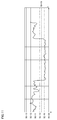
図12は、実施形態の変形例に従うピーク値付近以外のパワー積算値の変動について説明する図である。判定部204は、上記の方式に従って当該パワー積算値の変動のデータを生成する。
図12に示されるように、時間に従って変動する場合が示されている。
点線は、10分毎の平均値を示したものである。
点線は、10分毎の平均値を示したものである。
判定部204は、一例として、本例においては閾値を1に設定し、平均値が閾値(「1」)であるか否かに基づいて睡眠時において覚醒状態であるかあるいは安静状態であるかを判定する。
なお、被検者が在室している場合に、睡眠時の状態を判定する。したがって、被検者が在室している期間における判定であり、不在の場合には判定しない。
図12においては、一例として、在室している場合と不在の場合とが示されており、在室している場合において睡眠時の状態を判定する。主として判定部204における処理である。
図13は、睡眠時における安静状態および覚醒状態の判定を説明する図である。
図13を参照して、図12のパワー積算値に対して閾値(「1」)以下が否かを判定する。閾値(「1」)以下である場合には、安静状態であると判定し、閾値(「1」)を超える場合には、覚醒状態であると判定する。
図13を参照して、図12のパワー積算値に対して閾値(「1」)以下が否かを判定する。閾値(「1」)以下である場合には、安静状態であると判定し、閾値(「1」)を超える場合には、覚醒状態であると判定する。
当該判定結果に基づいて被検者の睡眠時の状態を把握することが可能である。すなわち、睡眠時に安静状態の期間が長ければ良好な睡眠状態であると判定することが可能である。例えば、所定期間以上の睡眠時の安静状態が確保されているか否かに基づいて良好な睡眠状態か否かを判定することが可能である。
一方で、睡眠時の覚醒状態の期間が長ければ不良な睡眠状態であると判定することが可能である。
例えば、所定期間以上の睡眠時の覚醒状態が係属しているか否かに基づいて不良な睡眠状態か否かを判定することが可能である。
これにより被検者の睡眠状態に対して精度の高い分析が可能となる。
なお、本例においては、センサデータのスペクトルデータについて、ピーク値付近以外のパワー積算値を算出して、睡眠時の安静状態あるいは覚醒状態を判定する方式について説明したが他の方式を採用することも当然に可能である。
なお、本例においては、センサデータのスペクトルデータについて、ピーク値付近以外のパワー積算値を算出して、睡眠時の安静状態あるいは覚醒状態を判定する方式について説明したが他の方式を採用することも当然に可能である。
具体的には、ピーク値付近のパワー積算値とピーク値付近以外のパワー積算値との比を算出するようにしてもよい。睡眠時の安静状態である場合には、ピーク値付近以外のパワー積算値が小さくなるため比は0となる。一方で、睡眠時の覚醒状態である場合には、ピーク値付近以外のパワー積算値が大きくなるため比は1に近づくことになる。
したがって、ピーク値付近のパワー積算値とピーク値付近以外のパワー積算値との比を算出することにより、所定の閾値との比較により睡眠時の安静状態あるいは覚醒状態を判定するようにしてもよい。
本実施形態の変形例に従う方式は、スペクトルデータのピーク値を含む所定範囲のパワーと、所定範囲以外の領域のパワーとの比較に基づいて判定されるため被検者の生体情報の信号レベルが低い場合であっても精度の高い被検者の状態を把握することが可能である。
なお、本例においては、管理サーバー200が解析部202および判定部204を有する場合について説明したが、特にこれに限られずセンサーボックス119に当該機能を設けることにより1つの状態監視装置とすることも当然に可能である。
今回開示された実施の形態はすべての点で例示であって制限的なものではないと考えられるべきである。本発明の範囲は上記した説明ではなくて請求の範囲によって示され、請求の範囲と均等の意味および範囲内でのすべての変更が含まれることが意図される。
本技術は、病院、老人ホーム、養護施設その他の施設で取得される情報に適用可能である。
100 システム、101,221 制御装置、106 ドップラーセンサー、107 無線通信装置、108 記憶装置、109 ドア、110,120 居室、111,121,910,920,930,950 入居者、112 タンス、113 ベッド、114 トイレ、115 ケアコール子機、116 トイレセンサー、117 センサー、118 ドアセンサー、119 センサーボックス、130 管理センター、140 アクセスポイント、141,142 介護者、143,144 携帯端末、150 クラウドサーバー、190 ネットワーク、200 管理サーバー、226 ディスプレイ、229 入力デバイス、241 ケアコールボタン、290 バイタルセンサー、300 コンピューターシステム。
Claims (9)
- 被検者にマイクロ波を照射して、前記被検者から反射された反射波を検出する検出部と、
前記検出部で検出した反射波を解析して呼吸信号のスペクトルデータを取得する解析部と、
前記呼吸信号のスペクトルデータに基づいて前記被検者の睡眠時の状態を判定する判定部とを備える、状態監視装置。 - 前記判定部は、前記呼吸信号のスペクトルデータの波形線幅が所定値よりも大きい場合に睡眠時の覚醒状態と判定し、前記呼吸信号のスペクトルデータの波形線幅が所定値以下の場合に睡眠時の安静状態と判定する、請求項1記載の状態監視装置。
- 前記呼吸信号のスペクトルデータは、所定期間毎にピーク値を有し、
前記判定部は、所定期間毎のピーク値の最大値を所定値に規格化し、前記呼吸信号のスペクトルデータの波形線幅が所定値よりも大きい場合に睡眠時の覚醒状態と判定し、前記呼吸信号のスペクトルデータの波形線幅が所定値以下の場合に睡眠時の安静状態と判定する、請求項2記載の状態監視装置。 - 前記判定部は、
前記呼吸信号のパワースペクトルデータを生成し、
前記パワースペクトラムデータが所定値以上であるか否かを判定し、
前記パワースペクトラムデータが所定値以上である場合には前記被検者の在室状態として判定し、
前記パワースペクトラムデータが所定値未満である場合には前記被検者の不在状態として判定する、請求項1記載の状態監視装置。 - 前記呼吸信号のスペクトルデータは、ピーク値を示す周波数領域と、それ以外の周波数領域とに分割され、
前記判定部は、前記ピーク値を示す周波数領域のスペクトルデータのパワー積算値と、前記それ以外の周波数領域のスペクトルデータのパワー積算値との比または差分が所定値以上である場合には睡眠時の覚醒状態と判定し、前記比または差分が所定値未満である場合には、睡眠時の安静状態と判定する、請求項1記載の状態監視装置。 - 被検者にマイクロ波を照射して、前記被検者から反射された反射波を検出するステップと、
検出した反射波を解析して呼吸信号のスペクトルデータを取得するステップと、
前記呼吸信号のスペクトルデータに基づいて前記被検者の睡眠時の状態を判定するステップとを備える、状態監視方法。 - 前記被験者の睡眠時の状態を判定するステップは、前記呼吸信号のスペクトルデータの波形線幅が所定値よりも大きい場合に睡眠時の覚醒状態と判定し、前記呼吸信号のスペクトルデータの波形線幅が所定値以下の場合に睡眠時の安静状態と判定する、請求項6記載の状態監視方法。
- 前記被験者の睡眠時の状態を判定するステップは、前記呼吸信号のスペクトルデータは、所定期間毎にピーク値を有し、
所定期間毎のピーク値の最大値を所定値に規格化し、前記呼吸信号のスペクトルデータの波形線幅が所定値よりも大きい場合に睡眠時の覚醒状態と判定し、前記呼吸信号のスペクトルデータの波形線幅が所定値以下の場合に睡眠時の安静状態と判定する、請求項7記載の状態監視方法。 - 前記呼吸信号のスペクトルデータは、ピーク値を示す周波数領域と、それ以外の周波数領域とに分割され、
前記被験者の睡眠時の状態を判定するステップは、前記ピーク値を示す周波数領域のスペクトルデータのパワー積算値と、前記それ以外の周波数領域のスペクトルデータのパワー積算値との比または差分が所定値以上である場合には睡眠時の覚醒状態と判定し、前記比または差分が所定値未満である場合には、睡眠時の安静状態と判定する、請求項7記載の状態監視方法。
Priority Applications (1)
| Application Number | Priority Date | Filing Date | Title |
|---|---|---|---|
| JP2020550458A JP7468350B2 (ja) | 2018-10-02 | 2019-10-01 | 状態監視装置および状態監視装置の制御方法 |
Applications Claiming Priority (2)
| Application Number | Priority Date | Filing Date | Title |
|---|---|---|---|
| JP2018-187708 | 2018-10-02 | ||
| JP2018187708 | 2018-10-02 |
Publications (1)
| Publication Number | Publication Date |
|---|---|
| WO2020071374A1 true WO2020071374A1 (ja) | 2020-04-09 |
Family
ID=70054545
Family Applications (1)
| Application Number | Title | Priority Date | Filing Date |
|---|---|---|---|
| PCT/JP2019/038774 Ceased WO2020071374A1 (ja) | 2018-10-02 | 2019-10-01 | 状態監視装置および状態監視方法 |
Country Status (2)
| Country | Link |
|---|---|
| JP (1) | JP7468350B2 (ja) |
| WO (1) | WO2020071374A1 (ja) |
Cited By (3)
| Publication number | Priority date | Publication date | Assignee | Title |
|---|---|---|---|---|
| CN112837514A (zh) * | 2020-12-30 | 2021-05-25 | 山东沃尔德生物技术有限公司 | 老年人居家看护系统及看护方法 |
| WO2021230223A1 (ja) * | 2020-05-11 | 2021-11-18 | 国立大学法人東京大学 | 睡眠覚醒判定システム、睡眠覚醒判定装置、およびプログラム |
| JP2023133266A (ja) * | 2022-03-10 | 2023-09-22 | ビットセンシング インコーポレイテッド | レーダを利用して睡眠時間を分析する装置、方法及びコンピュータプログラム |
Citations (5)
| Publication number | Priority date | Publication date | Assignee | Title |
|---|---|---|---|---|
| JPH07204166A (ja) * | 1994-01-26 | 1995-08-08 | Matsushita Electric Ind Co Ltd | 監視装置 |
| JP2009538720A (ja) * | 2006-06-01 | 2009-11-12 | ビアンカメッド リミテッド | 生理的徴候を監視するための装置、システム、および方法 |
| WO2011019091A1 (ja) * | 2009-08-13 | 2011-02-17 | 帝人ファーマ株式会社 | 呼吸波形情報の演算装置及び呼吸波形情報を利用した医療機器 |
| JP2012170528A (ja) * | 2011-02-18 | 2012-09-10 | Citizen Holdings Co Ltd | 睡眠時無呼吸判定装置 |
| JP2017537710A (ja) * | 2014-12-11 | 2017-12-21 | コーニンクレッカ フィリップス エヌ ヴェKoninklijke Philips N.V. | 睡眠段階分類のスペクトル境界を決定するシステム及び方法 |
-
2019
- 2019-10-01 WO PCT/JP2019/038774 patent/WO2020071374A1/ja not_active Ceased
- 2019-10-01 JP JP2020550458A patent/JP7468350B2/ja active Active
Patent Citations (5)
| Publication number | Priority date | Publication date | Assignee | Title |
|---|---|---|---|---|
| JPH07204166A (ja) * | 1994-01-26 | 1995-08-08 | Matsushita Electric Ind Co Ltd | 監視装置 |
| JP2009538720A (ja) * | 2006-06-01 | 2009-11-12 | ビアンカメッド リミテッド | 生理的徴候を監視するための装置、システム、および方法 |
| WO2011019091A1 (ja) * | 2009-08-13 | 2011-02-17 | 帝人ファーマ株式会社 | 呼吸波形情報の演算装置及び呼吸波形情報を利用した医療機器 |
| JP2012170528A (ja) * | 2011-02-18 | 2012-09-10 | Citizen Holdings Co Ltd | 睡眠時無呼吸判定装置 |
| JP2017537710A (ja) * | 2014-12-11 | 2017-12-21 | コーニンクレッカ フィリップス エヌ ヴェKoninklijke Philips N.V. | 睡眠段階分類のスペクトル境界を決定するシステム及び方法 |
Cited By (4)
| Publication number | Priority date | Publication date | Assignee | Title |
|---|---|---|---|---|
| WO2021230223A1 (ja) * | 2020-05-11 | 2021-11-18 | 国立大学法人東京大学 | 睡眠覚醒判定システム、睡眠覚醒判定装置、およびプログラム |
| CN112837514A (zh) * | 2020-12-30 | 2021-05-25 | 山东沃尔德生物技术有限公司 | 老年人居家看护系统及看护方法 |
| JP2023133266A (ja) * | 2022-03-10 | 2023-09-22 | ビットセンシング インコーポレイテッド | レーダを利用して睡眠時間を分析する装置、方法及びコンピュータプログラム |
| JP7530118B2 (ja) | 2022-03-10 | 2024-08-07 | ビットセンシング インコーポレイテッド | レーダを利用して睡眠時間を分析する装置、方法及びコンピュータプログラム |
Also Published As
| Publication number | Publication date |
|---|---|
| JPWO2020071374A1 (ja) | 2021-09-09 |
| JP7468350B2 (ja) | 2024-04-16 |
Similar Documents
| Publication | Publication Date | Title |
|---|---|---|
| US20240203227A1 (en) | System and Method for Monitoring Life Signs of a Person | |
| JP7435459B2 (ja) | 状態監視装置および状態監視方法 | |
| US11317813B2 (en) | Multi-sensor, modular, subject observation and monitoring system | |
| JP7666508B2 (ja) | 被介護者の情報を提供するためにコンピューターで実行される方法、プログラム、および、情報提供装置 | |
| Huang et al. | Improve quality of care with remote activity and fall detection using ultrasonic sensors | |
| WO2020071374A1 (ja) | 状態監視装置および状態監視方法 | |
| JPWO2017221745A1 (ja) | 呼吸数表示装置及び呼吸数表示方法 | |
| JP7342863B2 (ja) | コンピュータで実行されるプログラム、情報処理システム、および、コンピュータで実行される方法 | |
| WO2017081995A1 (ja) | 被監視者監視装置および該方法ならびに被監視者監視システム | |
| WO2019049530A1 (ja) | データ処理装置、ケアサポートシステムおよびデータ処理方法 | |
| JP7310327B2 (ja) | 行動検知装置、それを備えるシステム、行動検知方法、および、プログラム | |
| JP7276336B2 (ja) | コンピュータで実行されるプログラム、情報処理システム、および、コンピュータで実行される方法 | |
| JPWO2020003951A1 (ja) | コンピューターで実行されるプログラム、情報処理装置、および、コンピューターで実行される方法 | |
| JP2023105966A (ja) | 入居者の状態の変化を検知するためにコンピューターによって実行される方法、プログラム、および、入居者の状態変化検出装置 | |
| CN211432928U (zh) | 监护系统 | |
| JP6766585B2 (ja) | 被監視者監視装置及び方法 | |
| JP7215481B2 (ja) | コンピューターで実行されるプログラム、情報処理装置、および、コンピューターで実行される方法 | |
| WO2021027244A1 (zh) | 监护系统和监护方法 | |
| JP2020057222A (ja) | 状態監視装置および状態監視方法 | |
| JP7327397B2 (ja) | コンピューターで実行されるプログラム、情報処理システム、および、コンピューターで実行される方法 | |
| JP7487577B2 (ja) | 介護スタッフを割り当てるためにコンピューターで実行される方法、プログラム、情報処理装置、および見守りシステム | |
| JP7225649B2 (ja) | 状態監視装置 | |
| JP7205540B2 (ja) | コンピューターで実行されるプログラム、情報処理装置、および、コンピューターで実行される方法 | |
| WO2020137061A1 (ja) | 情報表示方法、プログラムおよび情報表示装置 | |
| Fukuda et al. | A Comparison of Sensing Technologies on a Room-Exit Detection System |
Legal Events
| Date | Code | Title | Description |
|---|---|---|---|
| 121 | Ep: the epo has been informed by wipo that ep was designated in this application |
Ref document number: 19868923 Country of ref document: EP Kind code of ref document: A1 |
|
| ENP | Entry into the national phase |
Ref document number: 2020550458 Country of ref document: JP Kind code of ref document: A |
|
| NENP | Non-entry into the national phase |
Ref country code: DE |
|
| 122 | Ep: pct application non-entry in european phase |
Ref document number: 19868923 Country of ref document: EP Kind code of ref document: A1 |