WO2020067289A1 - 液滴出射装置 - Google Patents
液滴出射装置 Download PDFInfo
- Publication number
- WO2020067289A1 WO2020067289A1 PCT/JP2019/037859 JP2019037859W WO2020067289A1 WO 2020067289 A1 WO2020067289 A1 WO 2020067289A1 JP 2019037859 W JP2019037859 W JP 2019037859W WO 2020067289 A1 WO2020067289 A1 WO 2020067289A1
- Authority
- WO
- WIPO (PCT)
- Prior art keywords
- flow path
- droplet
- liquid
- outlet
- emitting device
- Prior art date
- Legal status (The legal status is an assumption and is not a legal conclusion. Google has not performed a legal analysis and makes no representation as to the accuracy of the status listed.)
- Ceased
Links
Images




Classifications
-
- B—PERFORMING OPERATIONS; TRANSPORTING
- B81—MICROSTRUCTURAL TECHNOLOGY
- B81B—MICROSTRUCTURAL DEVICES OR SYSTEMS, e.g. MICROMECHANICAL DEVICES
- B81B1/00—Devices without movable or flexible elements, e.g. microcapillary devices
-
- G—PHYSICS
- G01—MEASURING; TESTING
- G01N—INVESTIGATING OR ANALYSING MATERIALS BY DETERMINING THEIR CHEMICAL OR PHYSICAL PROPERTIES
- G01N1/00—Sampling; Preparing specimens for investigation
-
- G—PHYSICS
- G01—MEASURING; TESTING
- G01N—INVESTIGATING OR ANALYSING MATERIALS BY DETERMINING THEIR CHEMICAL OR PHYSICAL PROPERTIES
- G01N35/00—Automatic analysis not limited to methods or materials provided for in any single one of groups G01N1/00 - G01N33/00; Handling materials therefor
- G01N35/10—Devices for transferring samples or any liquids to, in, or from, the analysis apparatus, e.g. suction devices, injection devices
-
- G—PHYSICS
- G01—MEASURING; TESTING
- G01N—INVESTIGATING OR ANALYSING MATERIALS BY DETERMINING THEIR CHEMICAL OR PHYSICAL PROPERTIES
- G01N37/00—Details not covered by any other group of this subclass
Definitions
- the present invention relates to a droplet emitting device.
- Patent Literature 1 discloses that a sample droplet and oil are mixed and poured into a microarray plate, the droplet is arranged on the microarray, and the droplet is ionized by a laser. A technique for introducing the analyzer into an analytical instrument is disclosed.
- a liquid chromatograph mass spectrometer uses an electrospray ionization method in which an electric field is applied to a sample liquid from which components have been separated by chromatography, ionized, and then sprayed and introduced into an analytical instrument.
- electrospray ionization method only a few% of the sprayed sample is introduced into the analyzer, and the introduction rate is low. Therefore, it is difficult to perform high-accuracy analysis when the sample is very small.
- Non-Patent Document 1 the rate of introduction into the analytical instrument can be improved, but the sample may be lost due to the interaction between the sample and the oil. Therefore, even if such a technique is used, it is difficult to perform high-accuracy analysis when the sample is very small.
- the present invention provides a droplet emitting device that can introduce a sample into an analyzer so that highly accurate analysis is possible even if the amount of the sample liquid is very small.
- a droplet ejection device is formed along a first direction, is connected to a first flow path through which a liquid flows, and a second flow path that is connected to an outlet of the first flow path and intersects the first direction.
- the third flow path is connected to the outlet of the first flow path, the outlet of the second flow path, and the outlet of the third flow path, is formed along the first direction, is wider than the first flow path, A fourth flow path through which gas flows, a fifth flow path connected to an outlet of the fourth flow path and formed along a fourth direction intersecting the first direction, through which gas flows, and a fourth flow path A sixth flow path connected to the outlet and formed along a fifth direction intersecting the first direction and the fourth direction, through which gas flows, an outlet of the fourth flow path, and a fifth flow path Is connected to the outlet of the outlet and the sixth flow path is formed along a first direction, comprising width than the fourth flow path is large, and the seventh flow path liquid and gas flows, a.
- the sample liquid is elongated in the first direction by the gas flowing through the second flow path and the third flow path and merging with the fourth flow path.
- the sample liquid is cut into droplets by the gas flowing through the fifth flow path and the sixth flow path and joining at the seventh flow path, and is emitted in the first direction.
- the flow rate of the liquid flowing through the first flow path is determined by the flow rate of the gas flowing through the second flow path, the flow rate of the gas flowing through the third flow path, the flow rate of the gas flowing through the fifth flow path, and the sixth flow path.
- the pressure of the gas flowing through the second flow path and the pressure of the gas flowing through the third flow path are smaller than the flow velocity of the flowing gas, and the pressure of the gas flowing through the fifth flow path and the pressure of the gas flowing through the sixth flow path, respectively. May be higher than the pressure.
- the sample liquid flowing through the first flow path is emitted as a droplet in the first direction without flowing backward to the second flow path, the third flow path, the fifth flow path, and the sixth flow path.
- the surfaces of the second flow path, the third flow path, the fourth flow path, the fifth flow path, the sixth flow path, and the seventh flow path may be coated with a hydrophobic coating.
- the sample liquid hardly adheres to the surfaces of the second flow path, the third flow path, the fourth flow path, the fifth flow path, the sixth flow path, and the seventh flow path. , And the ejection of the liquid droplets in the seventh flow path is appropriately performed.
- the depth of the seventh flow path may be larger than the width of the fourth flow path.
- the droplet formed at the outlet of the fourth channel is prevented from touching the bottom surface and the top surface of the seventh channel, and the flight distance of the droplet can be extended.
- the second flow path and the third flow path may be formed axially symmetric with respect to the first direction.
- an axially symmetric force can be applied to the liquid flowing through the first flow path, and the liquid flows in the first direction.
- the liquid can be stretched stably along the direction.
- the fifth flow path and the sixth flow path may be formed axially symmetric with respect to the first direction.
- an axisymmetric force can be applied to the liquid flowing through the fourth flow path, and the liquid can be stably supplied. Drops can be emitted.
- the liquid flowing through the seventh flow path may form a droplet having a diameter inversely proportional to the pressure of the gas flowing through the fifth flow path or the square root of the pressure of the gas flowing through the sixth flow path.
- the diameter of the droplet can be adjusted by the pressure of the gas flowing through the fifth flow path or the pressure of the gas flowing through the sixth flow path, and the amount of the sample introduced into the analytical instrument can be finely controlled. can do.
- the diameter of the droplet may be proportional to the square root of the surface tension of the liquid.
- the diameter of the droplet can be adjusted according to the surface tension of the liquid flowing through the first flow path, and the amount of the sample introduced into the analyzer can be finely controlled.
- the droplet may be emitted from the fourth channel to the seventh channel at a predetermined cycle.
- a sample can be introduced into the analyzer in a constant amount per unit time.
- the predetermined cycle may be proportional to the flow rate of the liquid flowing through the first flow path.
- the amount of the sample introduced into the analyzer per unit time can be finely controlled.
- the Reynolds number calculated from the flow velocity of the gas flowing through the seventh flow path, the depth of the seventh flow path, and the kinematic viscosity coefficient of the gas may be 50 or more and less than 400.
- the flight distance of the droplet flowing through the seventh flow path can be made sufficiently long, and the rate of introduction of the sample into the analyzer can be improved.
- the liquid flowing through the first flow path may have components separated along the first direction.
- the sample liquid from which the components have been separated by chromatography can be emitted as droplets while maintaining the separated state, and introduced into the analytical instrument.
- the outlet of the seventh flow path may be connected to the inlet of the analyzer.
- the sample liquid can be ejected as droplets and introduced into the analyzer, and high-precision analysis can be performed even when the amount of the sample liquid is very small.
- a droplet ejecting apparatus capable of introducing a sample into an analyzer so as to enable high-precision analysis even when the amount of the sample liquid is very small.
- FIG. 1 is a diagram illustrating an outline of a mass spectrometry system including a droplet emitting device according to an embodiment of the present invention.
- FIG. 3 is a diagram illustrating a first substrate and a second substrate that constitute the droplet emitting device according to the embodiment.
- FIG. 4 is a diagram illustrating an enlarged image of the droplet emitting device according to the embodiment.
- FIG. 4 is a diagram illustrating an image obtained by continuously photographing a state in which droplets are emitted by the droplet emitting device according to the embodiment.
- FIG. 3 is a diagram showing a mass spectrum obtained by a mass spectrometry system including the droplet emitting device according to the present embodiment and a mass spectrum obtained by using an electrospray ionization method.
- FIG. 3 is a diagram showing a mass spectrum obtained by a mass spectrometry system including the droplet emitting device according to the present embodiment and a mass spectrum obtained by using an electrospray ionization method.
- FIG. 3 is a top view of the droplet emitting device according to the embodiment.
- FIG. 3 is a side view of the droplet emitting device according to the embodiment.
- FIG. 4 is a diagram illustrating the operation principle of the droplet emitting device according to the embodiment. It is a figure showing the conditions of pressure by which a droplet discharge device concerning this embodiment emits a droplet appropriately.
- FIG. 4 is a diagram illustrating a relationship between a diameter of a droplet formed by the droplet emitting device according to the embodiment and a second pressure.
- FIG. 4 is a diagram illustrating a relationship between a diameter of a droplet formed by the droplet emitting device according to the embodiment and a surface tension of the liquid.
- FIG. 4 is a diagram illustrating the operation principle of the droplet emitting device according to the embodiment. It is a figure showing the conditions of pressure by which a droplet discharge device concerning this embodiment emits a droplet appropriately.
- FIG. 4 is a diagram illustrating a relationship between a
- FIG. 4 is a diagram illustrating a relationship between the ejection frequency of droplets formed by the droplet ejection device according to the present embodiment and the flow rate of a liquid.
- FIG. 4 is a diagram illustrating a relationship between a diameter of a droplet formed by the droplet emitting device according to the embodiment and a flow rate of the liquid.
- FIG. 4 is a diagram illustrating a relationship between a flight distance of a droplet ejected by a droplet ejection device according to the embodiment and a second pressure.
- the present embodiment an embodiment according to one aspect of the present invention (hereinafter, referred to as “the present embodiment”) will be described with reference to the drawings.
- the components denoted by the same reference numerals have the same or similar configurations.
- FIG. 1 is a diagram showing an outline of a mass spectrometry system 1 including a droplet emitting device 10 according to the present embodiment.
- the mass spectrometry system 1 is one of application examples of the droplet emitting device 10 according to the present embodiment, and the droplet emitting device 10 may be connected to an analyzer other than the mass spectrometer 100.
- FIG. 2 is a diagram showing a first substrate 10a and a second substrate 10b that constitute the droplet emitting device 10 according to the present embodiment.
- the droplet emitting device 10 according to the present embodiment is configured by bonding a microchannel formed on a first substrate 10a and a microchannel formed on a second substrate 10b. More specifically, a shallow flow path (first flow path, second flow path, third flow path, and fourth flow path to be described later) and a deep flow path (fifth flow path to be described later) are formed in the first substrate 10a by etching.
- a flow path, a sixth flow path, and a seventh flow path are formed, and a deep flow path (fifth flow path, sixth flow path, and seventh flow path described later) is formed in the second substrate 10b by etching in the same manner.
- the droplet ejection device 10 is formed and bonded so that the deep flow paths of both members coincide with each other.
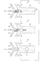
- FIG. 3 is a diagram showing an enlarged image of the droplet emitting device 10 according to the present embodiment.
- the droplet emitting device 10 includes a first channel C1, a second channel C2, a third channel C3, a fourth channel C4, a fifth channel C5, a sixth channel C6, and a seventh channel C7. .
- the first flow path C1 is formed along the first direction D1, through which the liquid flows.
- the flow rate of the liquid flowing through the first flow path C1 is arbitrary.
- components of the liquid flowing through the first flow path C1 may be separated along the first direction D1. As a result, the sample liquid from which the components have been separated by chromatography can be emitted as droplets while maintaining the separated state, and introduced into the analytical instrument.
- the second flow path C2 is connected to an outlet of the first flow path C1, is formed along a second direction D2 intersecting the first direction D1, and allows gas to flow.
- the third flow path C3 is connected to an outlet of the first flow path C1, is formed along a third direction D3 intersecting the first direction D1 and the second direction D2, and allows gas to flow.
- the second direction D2 and the third direction D3 may be inclined by about 60 ° with respect to the first direction D1, but the inclination is arbitrary.
- the same gas may flow through the second flow path C2 and the third flow path C3 at the same pressure (first pressure P g1 ).
- air may flow through the second flow path C2 and the third flow path C3.
- the fourth flow path C4 is connected to the outlet of the first flow path C1, the outlet of the second flow path C2, and the outlet of the third flow path C3, is formed along the first direction D1, and is formed from the first flow path C1.
- the width is large, and liquid and gas flow.
- the liquid flowing through the first flow path C1 collides with the gas flowing through the second flow path C2 and the third flow path C3 and merging with the fourth flow path C4 at the outlet of the first flow path C1, and is dragged by the flow of the gas. Thus, it is extended in the first direction D1 in the fourth flow path C4.
- the second flow path C2 and the third flow path C3 may be formed axially symmetric with respect to the first direction D1.
- an axially symmetric force can be applied to the liquid flowing through the first flow path C1.
- the liquid can be stably stretched along the direction D1.
- the fifth flow path C5 is connected to an outlet of the fourth flow path C4, is formed along a fourth direction D4 intersecting with the first direction D1, and allows gas to flow.
- the sixth flow path C6 is connected to the outlet of the fourth flow path C4, is formed along a fifth direction D5 intersecting the first direction D1 and the fourth direction D4, and allows gas to flow.
- the fifth direction D5 and the sixth direction D6 may be inclined by about 60 ° with respect to the first direction D1, but the inclination is arbitrary.
- the fifth direction D5 may be parallel to the second direction D2, and the sixth direction D6 may be parallel to the third direction D3.
- the same gas may flow through the fifth flow path C5 and the sixth flow path C6 at the same pressure (the second pressure P g2 ).
- air may flow through the fifth flow path C5 and the sixth flow path C6.
- the seventh channel C7 is connected to the outlet of the fourth channel C4, the outlet of the fifth channel C5, and the outlet of the sixth channel C6, is formed along the first direction D1, and is formed from the third channel C3.
- the width is large, and liquid and gas flow.
- the liquid extended in the fourth flow path C4 collides with the gas flowing in the fifth flow path C5 and the sixth flow path C6 and joining in the seventh flow path C7 at the outlet of the fourth flow path C4, and It receives the drag in the direction D1.
- the drag applied to the liquid balances the surface tension generated in the direction opposite to the first direction D1, but the liquid flows, so that the droplet grows at the outlet of the fourth flow path C4.
- the drag applied to the droplet increases as the diameter of the droplet increases, and when the drag exceeds the surface tension, the droplet is separated due to Rayleigh instability and emitted in the first direction D1.
- the outlet of the seventh flow path C7 may be connected to the inlet of an analytical instrument such as the mass spectrometer 100.
- the fifth flow path C5 and the sixth flow path C6 may be formed axially symmetric with respect to the first direction D1.
- an axially symmetric force can be applied to the liquid flowing through the fourth flow path C4, and the liquid can be stabilized. Droplets can be emitted.
- the droplet emitting device 10 by flowing a small amount of the sample liquid through the first flow path C1, the liquid drops flow through the second flow path C2 and the third flow path C3, and merge at the fourth flow path C4.
- the sample liquid is extended in the first direction D1 by the flowing gas, and the sample liquid is cut into droplets by the gas flowing through the fifth flow path C5 and the sixth flow path C6 and joining at the seventh flow path C7.
- the surfaces of the second flow path C2, the third flow path C3, the fourth flow path C4, the fifth flow path C5, the sixth flow path C6, and the seventh flow path C7 may be coated with a hydrophobic coating. This makes it difficult for the sample liquid to adhere to the surfaces of the second flow path C2, the third flow path C3, the fourth flow path C4, the fifth flow path C5, the sixth flow path C6, and the seventh flow path C7.
- the extension of the liquid in the fourth flow path C4 and the ejection of the droplets in the seventh flow path C7 are appropriately performed.
- FIG. 4 is a view showing an image obtained by continuously photographing a state in which a droplet is emitted by the droplet emitting device 10 according to the present embodiment.
- a fourth image taken later and a fifth image taken 133 ⁇ s after the initial time t 0 are shown.
- the flow rate of the liquid flowing through the first flow path C1 is 5 ⁇ L / min
- the pressure of the gas flowing through the second flow path C2 and the third flow path C3 is 80 kPa
- the pressure of the gas flowing through the passage and the sixth passage is 20 kPa.
- the first image shows a state in which the droplet D is starting to be formed at the outlet of the fourth flow path C4. At the right end of the first image, the droplet emitted in the previous cycle is photographed.
- the second image shows that the droplet D is formed at the outlet of the fourth flow path C4 and is growing.
- the diameter of the droplet D formed at the outlet of the fourth flow path C4 is larger than that in the case of the second image, and shows a state immediately before separation.
- the fourth image shows a state in which the diameter of the droplet D is further larger than in the case of the third image, and the droplet D is separated and emitted to the seventh flow path C7.
- the fifth image shows a state in which the droplet D emitted to the seventh flow path C7 is flying.
- the droplet ejection device 10 repeats the ejection process of the droplet D shown in FIG. 4 at a predetermined cycle.
- the diameter of the droplet D is about 29 ⁇ m
- the frequency of emission is about 6.3 kHz. That is, the emission cycle is about 160 ⁇ s. Note that the diameter of the droplet D can be further increased or decreased. Further, the frequency of emission can be higher or lower.
- the sample liquid can be separated into droplets and emitted, and the sample can be introduced into the analyzer at an introduction rate of almost 100%. Further, since the sample liquid is separated into droplets by gas and the sample liquid is not mixed with another liquid such as oil, a small amount of the sample can be introduced into the analyzer without loss.
- the droplet emitting device 10 can also be used as a pipetting device. Conventionally, the pipetting of a small amount of the sample liquid has been performed by ink jet, but the droplet emitting device 10 according to the present embodiment is superior to the ink jet in the following three points. First, since the inkjet requires a pressurized chamber, the volume of the sample liquid to be pipetted can be reduced only to about mL. However, according to the droplet ejection device 10 according to the present embodiment, several tens of Since a droplet having a diameter of ⁇ m can be formed, the sample liquid can be pipetted on the order of ⁇ L to nL.
- the inkjet needs to store about mL of liquid in the pressurized chamber, even if the sample liquid is separated into components, it may be necessary to mix the sample liquid in the pressurized chamber.
- the sample liquid from which the components have been separated can be directly emitted as droplets, and a small amount of the sample liquid component can be separated and pipetted.
- the flow path can be easily washed in a relatively short time by flowing a washing liquid such as water, so that pipetting can be easily performed without mixing different sample liquids.
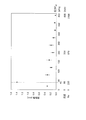
- FIG. 5 is a diagram showing a mass spectrum obtained by the mass spectrometry system 1 including the droplet emitting device 10 according to the present embodiment and a mass spectrum obtained by using the electrospray ionization method.
- the mass spectrum obtained from the mass spectrometry system 1 including the droplet emitting device 10 according to the present invention is shown by a solid line
- the mass spectrum obtained by using the electrospray ionization method is shown by a broken line.
- the vertical axis indicates the signal value (cps: counts per second)
- the horizontal axis indicates the mass-to-charge ratio (m / z).
- caffeine 5 ⁇ M and formic acid 0.1% are used as sample liquids.
- the mass spectrometry system 1 including the droplet ejection device 10 according to the present embodiment can obtain about 20 times the signal value of the mass spectrum as compared with the conventional electrospray ionization method. Can be read. This is because almost all of the minute amount of the sample liquid can be introduced into the mass spectrometer 100 by the droplet emitting device 10 according to the present embodiment. As described above, according to the droplet emitting device 10 according to the present embodiment, the sample can be introduced into the analyzer so that highly accurate analysis can be performed.
- FIG. 6 is a top view of the droplet emitting device 10 according to the present embodiment.
- the figure shows a state in which the liquid flows at the flow rate U 1 in the first flow path C 1 , a droplet D is formed at the outlet of the fourth flow path C 4, and is emitted to the seventh flow path C 7.
- the surface tension and the drag applied to the growing droplet D at the outlet of the fourth flow path C4 are shown, and the second flow path C2, the third flow path C3, the fourth flow path C4, the fifth flow
- the streamlines of the gas flowing through the path C5, the sixth flow path, and the seventh flow path C7 are indicated by broken lines.
- the width w2 of the fourth flow path C4 is larger than the width w1 of the first flow path C1. This prevents the liquid extended in the fourth flow path C4 from coming into contact with the wall surface of the fourth flow path C4.
- the width w3 of the seventh flow path C7 is larger than the width w2 of the fourth flow path C4. This prevents the droplet formed at the outlet of the fourth flow path C4 from coming into contact with the wall surface of the seventh flow path C7.
- the flow velocity U 1 of the liquid flowing through the first flow path C 1 is determined by the flow velocity U g1 of the gas flowing through the second flow path C 2 and the flow velocity U 1 of the gas flowing through the third flow path C 3. g1, smaller than either of the flow velocity U g2 of the gas flowing through the flow velocity U g2 and the sixth flow path C6 of the gas flowing through the fifth flow path C5.
- the sample liquid flowing in the first flow path C1 does not flow back to the second flow path C2, the third flow path C3, the fifth flow path C5, and the sixth flow path C6, It is emitted as a droplet in the direction D1.
- FIG. 7 is a side view of the droplet emitting device 10 according to the present embodiment.
- FIG. 1 shows a first flow path C1, a fourth flow path C4, and a seventh flow path C7.
- the depth d2 of the seventh flow path C7 is larger than the width w2 of the fourth flow path C4.
- the droplet D formed at the outlet of the fourth flow path C4 is prevented from touching the bottom surface and the top surface of the seventh flow path C7, and the flying distance of the droplet d can be extended.
- the depth of the first flow path C1 and the depth of the fourth flow path C4 are the same at d1, and are smaller than the depth d2 of the seventh flow path C7.
- the bottom surface of the seventh flow passage C7 is formed lower than the bottom surfaces of the first flow passage C1 and the fourth flow passage C4, and the top surface of the seventh flow passage C7 is formed of the first flow passage C1 and the fourth flow passage C4. It is formed higher than the top surface of C4.
- the droplet formed at the outlet of the fourth flow path C4 is prevented from touching the bottom surface and the top surface of the seventh flow path C7, and the flying distance of the droplet d can be extended.
- Such a structure can be realized by a simple process by forming the droplet emitting device 10 by bonding the first substrate 10a and the second substrate 10b.
- FIG. 8 is a diagram illustrating the operation principle of the droplet emitting device 10 according to the present embodiment.
- the droplet D is separated from the first stage in which the formation of the droplet D starts at the outlet of the fourth flow channel C4, the second stage in which the droplet D grows at the outlet of the fourth flow channel C4.
- a third stage of emission to the seventh flow path C7 is shown.
- the droplet emitting device 10 repeatedly emits the droplet D by repeating the first stage, the second stage, and the third stage at a predetermined cycle.
- the liquid extended in the fourth flow path C4 flows through the fifth flow path C5 and the sixth flow path C6 and joins with the gas which joins in the seventh flow path C7 and the outlet of the fourth flow path C4. And receives a drag in the first direction D1.
- the drag applied to the liquid is proportional to the radius R of the droplet D, and balances the surface tension generated in the direction opposite to the first direction D1.
- the surface tension is proportional to the contact area A between the growing droplet D and the liquid extending to the fourth flow path C4.
- the droplet D emitted in the first direction D1 flies in the seventh flow path C7.
- the flight distance of the droplet D varies depending on the flow velocity of the gas flowing through the seventh flow path C7, the depth d2 of the seventh flow path C7, and the Reynolds number Re calculated from the kinematic viscosity coefficient ⁇ of the gas. For example, when the Reynolds number Re is about 200, the flight distance is about 30 times the depth d2 of the seventh flow path C7.
- the diameter 2R of the ejected droplet D is proportional to the square root of the surface tension ⁇ of the liquid, and the pressure P g2 of the gas flowing through the fifth flow path C5 or the sixth flow path C6 It is shown to be inversely proportional to the square root of the pressure P g2 of the gas flowing through. From such a relationship, the diameter 2R of the droplet D can be adjusted by the pressure P g2 of the gas flowing through the fifth flow path C5 or the pressure P g2 of the gas flowing through the sixth flow path C6. The amount of sample to be performed can be finely controlled. Further, the diameter 2R of the droplet D can be adjusted according to the surface tension ⁇ of the liquid flowing in the first flow path C1, and the amount of the sample introduced into the analyzer can be finely controlled.
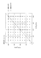
- FIG. 9 is a diagram illustrating conditions of pressure at which droplets are appropriately ejected by the droplet ejection device 10 according to the present embodiment.
- the vertical axis shows the pressure (second pressure P g2 ) of the gas flowing through the fifth flow path C5 and the sixth flow path C6 in kPa
- the horizontal axis shows the second flow path C2 and the third flow path.
- the pressure (first pressure P g1 ) of the gas flowing through C3 is indicated in units of kPa, and when the flow rate of the liquid flowing through the first flow path C1 is 5 ⁇ L / min, the case where droplet ejection is possible is indicated by “ ⁇ ”.
- ⁇ the case where droplet ejection is possible is plotted with “x”.
- droplets are ejected appropriately when P g2 ⁇ P g1 ⁇ P g2 +100.
- the droplet is not necessarily not ejected at all but may be ejected to some extent.
- FIG. 10 is a diagram showing the relationship between the diameter 2R of the droplet formed by the droplet emitting device 10 according to the present embodiment and the second pressure P g2 .
- the vertical axis indicates the diameter 2R of the droplet in units of ⁇ m
- the horizontal axis indicates the pressure (second pressure P g2 ) of the gas flowing through the fifth channel C5 and the sixth channel C6 in units of kPa. Is shown.
- the case where the first pressure P g1 is 60 kPa is plotted by a circle
- the case where the first pressure P g1 is 80 kPa is plotted by a triangle
- the case where the first pressure P g1 is 100 kPa is a square.
- the liquid flowing through the seventh flow path C7 is a droplet having a diameter inversely proportional to the square root of the pressure (second pressure P g2 ) of the gas flowing through the fifth flow path C5 and the sixth flow path C6.
- the second pressure P g2 is in the range of 20 kPa to 70 kPa and the first pressure P g1 is in the range of 60 kPa to 120 kPa
- the diameter 2R of the droplet is inversely proportional to the square root of the second pressure P g2. It is confirmed that there is.
- the diameter 2R of the droplet can be adjusted by the pressure P g2 of the gas flowing through the fifth flow path C5 and the sixth flow path C6, and the amount of the sample introduced into the analytical instrument can be finely controlled. Can be.
- FIG. 11 is a diagram showing the relationship between the diameter 2R of the droplet formed by the droplet emitting device 10 according to the present embodiment and the surface tension ⁇ of the liquid.
- the vertical axis indicates the diameter 2R of the droplet in units of ⁇ m
- the horizontal axis indicates the surface tension ⁇ of the liquid in units of N / m.
- the relationship between the diameter 2R of the droplet and the surface tension ⁇ is plotted while the surface tension ⁇ is changed by changing the mixing ratio of the two types of liquids and the other conditions are kept constant.
- the flow rate of the liquid flowing through the first flow path C1 is 5 ⁇ L / min.
- a function proportional to the square root of the surface tension ⁇ of the liquid is shown by a solid line.
- the diameter 2R of the droplet is proportional to the square root of the surface tension ⁇ of the liquid.
- the figure confirms that the diameter 2R of the droplet is proportional to the square root of the surface tension ⁇ when the surface tension ⁇ is in the range of 0.02 N / m to 0.07 N / m.
- the diameter 2R of the droplet can be adjusted according to the surface tension ⁇ of the liquid flowing through the first flow path C1, and the amount of the sample introduced into the analyzer can be finely controlled.
- FIG. 12 is a diagram showing the relationship between the ejection frequency of droplets formed by the droplet ejection device 10 according to the present embodiment and the flow rate of liquid.
- the vertical axis indicates the frequency of ejection of the liquid droplet in units of kHz
- the horizontal axis indicates the flow rate of the liquid in units of ⁇ L / min.
- the relationship between the ejection frequency of the droplet and the flow rate is plotted while the flow rate of the liquid is changed and other conditions are kept constant.
- the droplet emitting device 10 emits droplets from the fourth channel C4 to the seventh channel C7 at a predetermined cycle.
- the predetermined cycle is proportional to the flow velocity of the liquid flowing through the first flow path C1.
- the ejection frequency of the droplet is proportional to the flow rate of the liquid flowing through the first flow path C1. Is confirmed.
- the droplet ejection device 10 As described above, according to the droplet ejection device 10 according to the present embodiment, by ejecting a droplet having a certain diameter at a predetermined cycle, it is possible to introduce a sample into the analyzer in a constant amount per unit time. it can. Further, according to the droplet emitting device 10 according to the present embodiment, the amount of the sample introduced into the analyzer per unit time can be finely controlled by the flow rate of the liquid flowing through the first flow path C1.
- FIG. 13 is a diagram showing the relationship between the diameter 2R of the droplet formed by the droplet emitting device 10 according to the present embodiment and the flow rate of the liquid.
- the vertical axis indicates the diameter 2R of the droplet in units of ⁇ m
- the horizontal axis indicates the flow rate of the liquid in units of ⁇ L / min.
- the relationship between the diameter 2R of the droplet and the flow rate is plotted while the flow rate of the liquid is changed and other conditions are kept constant.
- the diameter 2R of the droplet depends on the second pressure P g2 and the surface tension ⁇ of the liquid, but does not depend on the flow rate of the liquid flowing through the first flow path C1. According to the figure, when the flow rate of the liquid flowing through the first flow path C1 is in the range of 1 ⁇ L / min to 9 ⁇ L / min, the diameter 2R of the droplet is almost constant with respect to the flow rate of the liquid flowing through the first flow path C1. It is confirmed that there is.
- the ejection frequency of the droplet can be controlled independently. That is, the ejection frequency of the droplet is controlled by the flow rate of the liquid flowing through the first flow path C1, and the diameter 2R of the droplet is controlled by the pressure P g2 of the gas flowing through the fifth flow path C5 and the sixth flow path C6. can do.
- the droplet ejection device 10 even if the ejection amount of the sample liquid per unit time is the same, the ejection frequency is reduced by enlarging the droplet or the ejection frequency is decreased by decreasing the droplet. Can be set higher, and more precise pipetting and introduction to analytical instruments can be performed.
- FIG. 14 is a diagram showing the relationship between the flight distance of the droplet ejected by the droplet ejection device 10 according to the present embodiment and the second pressure.
- the vertical axis indicates the flight distance of the droplet in mm
- the horizontal axis indicates the pressure (second pressure P g2 ) of the gas flowing through the fifth flow path C5 and the sixth flow path C6 in kPa. Is shown.
- the horizontal axis shows the value obtained by converting the second pressure P g2 into the flow velocity of the gas flowing through the fifth flow path C5 and the sixth flow path C6 in units of m / s.
- the horizontal axis indicates a value obtained by converting the second pressure P g2 into a Reynolds number Re.
- the Reynolds number Re U calculated from the flow velocity U g2 of the gas flowing through the seventh flow path C7, the depth d2 of the seventh flow path C7, and the kinematic viscosity coefficient ⁇ of the gas.
- g2 d2 / v may be 50 or more and less than 400.
- the Reynolds number Re may be 100 or more and less than 300, and more preferably, the Reynolds number Re may be 150 or more and less than 250.
- the Reynolds number Re is 220.
- the flight distance of the droplet is about 1.4 mm when the depth of the seventh flow path C7 is 50 ⁇ m.
- the Reynolds number Re is 879, Is about 0.1 mm.
- the flight distance of the droplet flowing through the seventh flow path C7 can be sufficiently increased, and the sample can be analyzed.
- the introduction rate introduced into the device can be improved.
- the droplet emitting device 10 according to the present embodiment can be used as an interface for collecting the entire amount of a trace amount of a sample liquid chemically treated by a liquid chromatography device, a capillary electrophoresis device, or the like, or introducing the entire amount to an analytical instrument.
- the analytical instrument may in particular be a mass spectrometer.
- the droplet emitting device 10 according to the present embodiment uses an extended nanochromatography (for example, Ishibashi, tMawatari, Kitamori, ”Highly efficient and and ultra-small volume separation by pressure-driven) using a 100 to 1000 nm channel as a separation column.
- the liquid sample can be used as an interface for introducing a small amount of the sample liquid separated by a liquid chromatography, a technique described in “small,” 8, “1237-1242,” 2012) into a mass spectrometer.
- This makes it possible to realize a highly sensitive separation analysis system in which the number of theoretical plates, which is an index of separation performance, is about 100,000.
- the droplet emitting device 10 according to the present embodiment can be used as a droplet generating unit of an interface device described in International Publication No. WO2018 / 056131.
Landscapes
- Chemical & Material Sciences (AREA)
- General Physics & Mathematics (AREA)
- Pathology (AREA)
- Physics & Mathematics (AREA)
- Health & Medical Sciences (AREA)
- Life Sciences & Earth Sciences (AREA)
- Immunology (AREA)
- Biochemistry (AREA)
- Analytical Chemistry (AREA)
- General Health & Medical Sciences (AREA)
- Engineering & Computer Science (AREA)
- Computer Hardware Design (AREA)
- Microelectronics & Electronic Packaging (AREA)
- Other Investigation Or Analysis Of Materials By Electrical Means (AREA)
- Sampling And Sample Adjustment (AREA)
Abstract
試料液体が微量であっても、高精度の分析が可能となるように試料を分析機器に導入することができる液滴出射装置を提供する。液滴出射装置10は、第1方向D1に沿って形成され、液体が流される第1流路C1と、第1流路の出口と接続され、気体が流される第2流路C2及び第3流路C3と、第1流路の出口、第2流路の出口及び第3流路の出口と接続され、第1方向に沿って形成され、液体及び気体が流される第4流路C4と、第4流路の出口と接続され、気体が流される第5流路C5及び第6流路C6と、第4流路の出口、第5流路の出口及び第6流路の出口と接続され、第1方向に沿って形成され、第4流路より幅が大きく、液体及び気体が流される第7流路C7と、を備える。
Description
本発明は、液滴出射装置に関する。
近年、質量分析計やDNAシーケンサ等の分析機器に導入される試料の流量は、μL(10-6リットル)/minやnL(10-9リットル)/minのオーダーにまで微量化している。また、ガラス等の基板に数10μmの幅及び深さを有するマイクロ流路を加工して、様々な化学操作を集積化するマイクロ流体デバイスも進展している。
マイクロ流体デバイスで処理された試料液体の質量分析に関し、下記特許文献1には、試料液滴と油を混合してマイクロアレイプレートに流し込み、マイクロアレイに液滴を配置した後、液滴をレーザでイオン化して分析機器に導入する技術が開示されている。
Simon K. Kuster、他6名、"Interfacing Droplet Microfluidics with Matrix-Assisted Laser Desorption/Ionization Mass Spectrometry: Label-Free Content Analysis of Single Droplets"、Anal. Chem., 2013, 85 (3), pp 1285-1289
例えば液体クロマトグラフ質量分析計では、クロマトグラフィーによって成分を分離した試料液体に電界を印加してイオン化し、噴霧することで分析機器に導入するエレクトロスプレーイオン化法が用いられている。しかしながら、エレクトロスプレーイオン化法では、噴霧した試料の数%が分析機器に導入されるに過ぎず、導入率が低いため、試料が微量の場合には高精度の分析が難しい。
この点、非特許文献1に記載の技術によれば、分析機器への導入率を向上させることができるが、試料と油の相互作用によって試料の損失が生じることがある。そのため、このような技術を用いても、試料が微量の場合には高精度の分析が難しい。
そこで、本発明は、試料液体が微量であっても、高精度の分析が可能となるように試料を分析機器に導入することができる液滴出射装置を提供する。
本発明の一態様に係る液滴出射装置は、第1方向に沿って形成され、液体が流される第1流路と、第1流路の出口と接続され、第1方向と交差する第2方向に沿って形成され、気体が流される第2流路と、第1流路の出口と接続され、第1方向及び第2方向と交差する第3方向に沿って形成され、気体が流される第3流路と、第1流路の出口、第2流路の出口及び第3流路の出口と接続され、第1方向に沿って形成され、第1流路より幅が大きく、液体及び気体が流される第4流路と、第4流路の出口と接続され、第1方向と交差する第4方向に沿って形成され、気体が流される第5流路と、第4流路の出口と接続され、第1方向及び第4方向と交差する第5方向に沿って形成され、気体が流される第6流路と、第4流路の出口、第5流路の出口及び第6流路の出口と接続され、第1方向に沿って形成され、第4流路より幅が大きく、液体及び気体が流される第7流路と、を備える。
この態様によれば、第1流路に微量な試料液体を流すことで、第2流路及び第3流路を流れて第4流路で合流する気体によって試料液体が第1方向に引き延ばされ、第5流路及び第6流路を流れて第7流路で合流する気体によって試料液体が液滴状に切り取られて、第1方向に向かって出射される。これにより、試料液体が微量であっても、高精度の分析が可能となるように試料を分析機器に導入することができる。
上記態様において、第1流路を流れる液体の流速は、第2流路を流れる気体の流速、第3流路を流れる気体の流速、第5流路を流れる気体の流速及び第6流路を流れる気体の流速のいずれよりも小さく、第2流路を流れる気体の圧力及び第3流路を流れる気体の圧力は、それぞれ、第5流路を流れる気体の圧力及び第6流路を流れる気体の圧力より大きくてもよい。
この態様によれば、第1流路を流れる試料液体が第2流路、第3流路、第5流路及び第6流路に逆流することなく、第1方向に液滴として出射される。
上記態様において、第2流路、第3流路、第4流路、第5流路、第6流路及び第7流路の表面は、疎水性コーティングされていてもよい。
この態様によれば、試料液体が第2流路、第3流路、第4流路、第5流路、第6流路及び第7流路の表面に付着しづらくなり、第4流路での液体の引き延ばし及び第7流路での液滴出射が適切に行われるようになる。
上記態様において、第7流路の深さは、第4流路の幅より大きくてもよい。
この態様によれば、第4流路の出口で形成された液滴が、第7流路の底面及び天面に触れることが防止され、液滴の飛距離を伸ばすことができる。
上記態様において、第2流路と第3流路は、第1方向に関して軸対称に形成されていてもよい。
この態様によれば、第2流路及び第3流路に第1圧力で気体を流すことで、第1流路を流れる液体に対して軸対称な力を加えることができ、第1方向に沿うように安定して液体を引き延ばすことができる。
上記態様において、第5流路と第6流路は、第1方向に関して軸対称に形成されていてもよい。
この態様によれば、第5流路及び第6流路に第2圧力で気体を流すことで、第4流路を流れる液体に対して軸対称な力を加えることができ、安定して液滴を出射することができる。
上記態様において、第7流路を流れる液体は、第5流路を流れる気体の圧力又は第6流路を流れる気体の圧力の平方根に反比例する直径を有する液滴を形成していてもよい。
この態様によれば、液滴の直径を、第5流路を流れる気体の圧力又は第6流路を流れる気体の圧力によって調整することができ、分析機器に導入する試料の量を微細にコントロールすることができる。
上記態様において、液滴の直径は、液体の表面張力の平方根に比例していてもよい。
この態様によれば、第1流路に流す液体の表面張力に応じて液滴の直径を調整することができ、分析機器に導入する試料の量を微細にコントロールすることができる。
上記態様において、液滴は、所定の周期で第4流路から第7流路へ出射されてもよい。
この態様によれば、ある直径を有する液滴を所定の周期で出射することで、単位時間あたり一定の量で試料を分析機器に導入することができる。
上記態様において、所定の周期は、第1流路を流れる液体の流速に比例していてもよい。
この態様によれば、単位時間あたりに分析機器に導入する試料の量を微細にコントロールすることができる。
上記態様において、第7流路を流れる気体の流速、第7流路の深さ及び気体の動粘性係数により算出されるレイノルズ数は、50以上400未満であってもよい。
この態様によれば、第7流路を流れる液滴の飛距離を十分に長くすることができ、試料が分析機器に導入される導入率を向上させることができる。
上記態様において、第1流路を流れる液体は、第1方向に沿って成分が分離されていてもよい。
この態様によれば、クロマトグラフィーによって成分が分離された試料液体を、分離状態を保ったまま液滴にして出射し、分析機器に導入することができる。
上記態様において、第7流路の出口は、分析機器の入口に接続されていてもよい。
この態様によれば、試料液体を液滴として出射して分析機器に導入することができ、試料液体が微量であっても高精度の分析が可能となる。
本発明によれば、試料液体が微量であっても、高精度の分析が可能となるように試料を分析機器に導入することができる液滴出射装置が提供される。
以下、本発明の一側面に係る実施の形態(以下、「本実施形態」と表記する。)を、図面に基づいて説明する。なお、各図において、同一の符号を付したものは、同一又は同様の構成を有する。
図1は、本実施形態に係る液滴出射装置10を含む質量分析システム1の概要を示す図である。本実施形態に係る液滴出射装置10は、Q=2μL/minの流量で流される試料液体を、所定の直径を有する液滴Dとして切り出して、所定の周期で出射する。質量分析システム1は、液体にV=3kVの電圧を印加して液滴Dをイオン化させるイオン化装置80と、液滴DをT=200℃で加熱して気化させるヒータ90と、試料イオンIのマススペクトルを分析する質量分析計100とを備える。
なお、質量分析システム1は、本実施形態に係る液滴出射装置10の応用例の一つであり、液滴出射装置10は、質量分析計100以外の分析機器に接続されてもよい。
図2は、本実施形態に係る液滴出射装置10を構成する第1基板10a及び第2基板10bを示す図である。本実施形態に係る液滴出射装置10は、第1基板10aに形成されたマイクロ流路と、第2基板10bに形成されたマイクロ流路とを貼り合わせて構成されている。より具体的には、エッチングにより、第1基板10aに浅い流路(後述する第1流路、第2流路、第3流路及び第4流路)と、深い流路(後述する第5流路、第6流路及び第7流路)とを形成し、同様にエッチングにより、第2基板10bに深い流路(後述する第5流路、第6流路及び第7流路)を形成して、両部材の深い流路が一致するように貼り合わされて液滴出射装置10が構成されている。
図3は、本実施形態に係る液滴出射装置10を拡大撮影した画像を示す図である。液滴出射装置10は、第1流路C1、第2流路C2、第3流路C3、第4流路C4、第5流路C5、第6流路C6及び第7流路C7を備える。
第1流路C1は、第1方向D1に沿って形成され、液体が流される。例えば、第1流路C1にはQ=2μL/minの流量で試料液体が第1方向D1に流されてよい。もっとも、第1流路C1に流される液体の流量は任意である。また、第1流路C1を流れる液体は、第1方向D1に沿って成分が分離されていてよい。これにより、クロマトグラフィーによって成分が分離された試料液体を、分離状態を保ったまま液滴にして出射し、分析機器に導入することができる。
第2流路C2は、第1流路C1の出口と接続され、第1方向D1と交差する第2方向D2に沿って形成され、気体が流される。また、第3流路C3は、第1流路C1の出口と接続され、第1方向D1及び第2方向D2と交差する第3方向D3に沿って形成され、気体が流される。ここで、第2方向D2及び第3方向D3は、第1方向D1に対して約60°傾いていてよいが、傾きは任意である。第2流路C2及び第3流路C3には、同じ圧力(第1圧力Pg1)で同じ気体が流されてよい。第2流路C2及び第3流路C3には、例えば空気が流されてよい。
第4流路C4は、第1流路C1の出口、第2流路C2の出口及び第3流路C3の出口と接続され、第1方向D1に沿って形成され、第1流路C1より幅が大きく、液体及び気体が流される。第1流路C1を流れる液体は、第2流路C2及び第3流路C3を流れて第4流路C4で合流する気体と第1流路C1の出口でぶつかり、気体の流れに引きずられて第4流路C4で第1方向D1に引き延ばされる。
第2流路C2と第3流路C3は、第1方向D1に関して軸対称に形成されていてよい。これにより、第2流路C2及び第3流路C3に第1圧力Pg1で気体を流すことで、第1流路C1を流れる液体に対して軸対称な力を加えることができ、第1方向D1に沿うように安定して液体を引き延ばすことができる。
第5流路C5は、第4流路C4の出口と接続され、第1方向D1と交差する第4方向D4に沿って形成され、気体が流される。また、第6流路C6は、第4流路C4の出口と接続され、第1方向D1及び第4方向D4と交差する第5方向D5に沿って形成され、気体が流される。ここで、第5方向D5及び第6方向D6は、第1方向D1に対して約60°傾いていてよいが、傾きは任意である。また、第5方向D5は第2方向D2と平行であってよく、第6方向D6は、第3方向D3と平行であってよい。第5流路C5及び第6流路C6には、同じ圧力(第2圧力Pg2)で同じ気体が流されてよい。第5流路C5及び第6流路C6には、例えば空気が流されてよい。
第7流路C7は、第4流路C4の出口、第5流路C5の出口及び第6流路C6の出口と接続され、第1方向D1に沿って形成され、第3流路C3より幅が大きく、液体及び気体が流される。第4流路C4で引き延ばされた液体は、第5流路C5及び第6流路C6を流れて第7流路C7で合流する気体と第4流路C4の出口でぶつかり、第1方向D1の抗力を受ける。液体に加わる抗力は、第1方向D1と反対方向に生じる表面張力と釣り合うが、液体が流れ込むため第4流路C4の出口で液滴が成長する。液滴に加わる抗力は、液滴の直径が大きくなるにつれて増大し、抗力が表面張力よりも大きくなると、液滴がレイリー不安定性により切り離され、第1方向D1に向かって出射される。第7流路C7の出口は、質量分析計100等の分析機器の入口に接続されていてよい。これにより、試料液体を液滴として出射して分析機器に導入することができ、試料液体が微量であっても高精度の分析が可能となる。
第5流路C5と第6流路C6は、第1方向D1に関して軸対称に形成されていてよい。これにより、第5流路C5及び第6流路C6に第2圧力Pg2で気体を流すことで、第4流路C4を流れる液体に対して軸対称な力を加えることができ、安定して液滴を出射することができる。
本実施形態に係る液滴出射装置10によれば、第1流路C1に微量な試料液体を流すことで、第2流路C2及び第3流路C3を流れて第4流路C4で合流する気体によって試料液体が第1方向D1に引き延ばされ、第5流路C5及び第6流路C6を流れて第7流路C7で合流する気体によって試料液体が液滴状に切り取られて、第1方向D1に向かって出射される。これにより、試料液体が微量であっても、高精度の分析が可能となるように試料を分析機器に導入することができる。
第2流路C2、第3流路C3、第4流路C4、第5流路C5、第6流路C6及び第7流路C7の表面は、疎水性コーティングされていてよい。これにより、試料液体が第2流路C2、第3流路C3、第4流路C4、第5流路C5、第6流路C6及び第7流路C7の表面に付着しづらくなり、第4流路C4での液体の引き延ばし及び第7流路C7での液滴出射が適切に行われるようになる。
図4は、本実施形態に係る液滴出射装置10により液滴が出射される様子を連続撮影した画像を示す図である。同図では、初期時刻t0に撮影した第1画像と、初期時刻t0から33μs後に撮影した第2画像と、初期時刻t0から67μs後に撮影した第3画像と、初期時刻t0から100μs後に撮影した第4画像と、初期時刻t0から133μs後に撮影した第5画像と、を示している。なお、本例の場合、第1流路C1に流される液体の流量は5μL/minであり、第2流路C2及び第3流路C3に流される気体の圧力は80kPaであり、第5流路及び第6流路に流される気体の圧力は20kPaである。
第1画像は、第4流路C4の出口に液滴Dが形成され始めている様子を示している。なお、第1画像の右端には、一つ前の周期に出射された液滴が撮影されている。
第2画像は、第4流路C4の出口に液滴Dが形成され、成長途中である様子を示している。第3画像は、第4流路C4の出口に形成された液滴Dの直径が、第2画像の場合よりも大きくなり、切り離される直前の様子を示している。第4画像は、液滴Dの直径が第3画像の場合よりさらに大きくなり、切り離されて第7流路C7に出射される様子を示している。第5画像は、第7流路C7に出射された液滴Dが飛行している様子を示している。
本実施形態に係る液滴出射装置10は、図4に示した液滴Dの出射の過程を所定の周期で繰り返す。本例の設定の場合、液滴Dの直径は、約29μmであり、出射の頻度は約6.3kHzである。すなわち、出射の周期は約160μsである。なお、液滴Dの直径は、さらに大きくもできるし、小さくもできる。また、出射の頻度は、さらに高頻度にもできるし、低頻度にもできる。
本実施形態に係る液滴出射装置10によれば、試料液体を液滴に分離して出射することができ、ほとんど100%の導入率で試料を分析機器に導入することができる。また、試料液体を気体によって液滴に分離させ、試料液体を油等の他の液体と混合させることが無いため、微量な試料を損失させることなく分析機器に導入することができる。
液滴出射装置10は、ピペッティング装置として用いることもできる。試料液体の微量のピペッティングは、従来、インクジェットで行われることがあったが、本実施形態に係る液滴出射装置10は、以下の三点でインクジェットより優れている。第一に、インクジェットは加圧チャンバを必要とするため、ピペッティングする試料液体の体積をmL程度までしか小さくすることができないが、本実施形態に係る液滴出射装置10によれば、数十μmの直径の液滴を形成することができるため、μL~nLのオーダーで試料液体をピペッティングすることができる。第二に、インクジェットは加圧チャンバにmL程度の液体を溜める必要があるため、試料液体を成分分離したとしても、加圧チャンバで混合せざるを得ない場合があるが、本実施形態に係る液滴出射装置10によれば、成分分離した試料液体をそのまま液滴にして出射することができ、微量な試料液体の成分を分離してピペッティングすることができる。第三に、インクジェットで異なる試料液体をピペッティングする場合、試料の混合を防ぐため相当の時間をかけて加圧チャンバを洗浄する必要があるが、本実施形態に係る液滴出射装置10によれば、水等の洗浄液を流すことで流路の洗浄を簡単に比較的短時間で行うことができるため、異なる試料液体を混合させずにピペッティングすることが容易にできる。
図5は、本実施形態に係る液滴出射装置10を含む質量分析システム1により得られたマススペクトルとエレクトロスプレーイオン化法を用いて得られたマススペクトルを示す図である。同図では、本発明による液滴出射装置10を含む質量分析システム1より得られたマススペクトルを実線で示し、エレクトロスプレーイオン化法を用いて得られたマススペクトルを破線で示している。同図では、縦軸に信号値(cps:counts per second)を示し、横軸に質量電荷比(m/z)を示している。なお、本例では、試料液体としてカフェイン5μM、ギ酸0.1%を用いている。
同図によれば、本実施形態に係る液滴出射装置10を含む質量分析システム1によって、従来法であるエレクトロスプレーイオン化法に対して、マススペクトルについて約20倍の信号値を得ることができることが読み取れる。これは、本実施形態に係る液滴出射装置10によって微量の試料液体のほとんど全量を質量分析計100に導入できるためである。このように、本実施形態に係る液滴出射装置10によれば、高精度の分析が可能となるように試料を分析機器に導入することができる。
図6は、本実施形態に係る液滴出射装置10の上面図である。同図では、第1流路C1に流速U1で液体が流され、第4流路C4の出口で液滴Dが形成され、第7流路C7に出射される様子を示している。同図では、第4流路C4の出口で成長中の液滴Dに加わる表面張力と、抗力とを示し、第2流路C2、第3流路C3、第4流路C4、第5流路C5、第6流路及び第7流路C7を流れる気体の流線を破線で示している。
第4流路C4の幅w2は、第1流路C1の幅w1よりも大きい。これにより、第4流路C4で引き延ばされる液体が、第4流路C4の壁面に接触することが防止される。また、第7流路C7の幅w3は、第4流路C4の幅w2より大きい。これにより、第4流路C4の出口で形成された液滴が、第7流路C7の壁面に接触することが防止される。
本実施形態に係る液滴出射装置10において、第1流路C1を流れる液体の流速U1は、第2流路C2を流れる気体の流速Ug1、第3流路C3を流れる気体の流速Ug1、第5流路C5を流れる気体の流速Ug2及び第6流路C6を流れる気体の流速Ug2のいずれよりも小さい。また、本実施形態に係る液滴出射装置10において、第2流路C2を流れる気体の圧力Pg1及び第3流路C3を流れる気体の圧力Pg1は、それぞれ、第5流路C5を流れる気体の圧力Pg2及び第6流路C6を流れる気体の圧力Pg2より大きい。このような関係を満たすことで、第1流路C1を流れる試料液体が第2流路C2、第3流路C3、第5流路C5及び第6流路C6に逆流することなく、第1方向D1に液滴として出射される。なお、第2流路C2及び第3流路C3を流れる気体の圧力(第1圧力Pg1)及び第6流路C6及び第7流路C7を流れる気体の圧力(第2圧力Pg2)と、液滴出射可否との関係については、後に図9を用いて詳細に説明する。
図7は、本実施形態に係る液滴出射装置10の側面図である。同図では、第1流路C1、第4流路C4及び第7流路C7を示している。本実施形態に係る液滴出射装置10では、第7流路C7の深さd2は、第4流路C4の幅w2より大きい。これにより、第4流路C4の出口で形成された液滴Dが、第7流路C7の底面及び天面に触れることが防止され、液滴dの飛距離を伸ばすことができる。
また、第1流路C1の深さ及び第4流路C4の深さは、それぞれd1で同じであり、第7流路C7の深さd2より小さい。ここで、第7流路C7の底面は、第1流路C1及び第4流路C4の底面より低く形成され、第7流路C7の天面は、第1流路C1及び第4流路C4の天面より高く形成されている。これにより、第4流路C4の出口で形成された液滴が、第7流路C7の底面及び天面に触れることが防止され、液滴dの飛距離を伸ばすことができる。このような構造は、第1基板10aと第2基板10bを貼り合わせて液滴出射装置10を構成することで、簡単な工程で実現できる。
図8は、本実施形態に係る液滴出射装置10の動作原理を説明する図である。同図では、第4流路C4の出口で液滴Dの形成が始まる第1段階と、第4流路C4の出口で液滴Dが成長する第2段階と、液滴Dが切り離されて第7流路C7に出射される第3段階とを示している。液滴出射装置10は、第1段階、第2段階及び第3段階を所定の周期で繰り返して、液滴Dを連続して出射する。
第1段階において、第4流路C4で引き延ばされた液体は、第5流路C5及び第6流路C6を流れて第7流路C7で合流する気体と第4流路C4の出口でぶつかり、第1方向D1の抗力を受ける。液体に加わる抗力は、液滴Dの半径Rに比例し、第1方向D1と反対方向に生じる表面張力と釣り合う。ここで、表面張力は、成長中の液滴Dと第4流路C4に延びる液体との接触面積Aに比例する。
第2段階では、液体が流れ込んで液滴が成長し、接触面積Aが一定のまま半径Rが大きくなるため、抗力が増大していく。そして、抗力が表面張力よりも大きくなると、液滴Dが抗力により引っ張られて、レイリー不安定性により切り離され、第1方向D1に向かって出射される。
第3段階では、第1方向D1に向かって出射された液滴Dが第7流路C7を飛行する。液滴Dの飛距離は、第7流路C7を流れる気体の流速、第7流路C7の深さd2及び気体の動粘性係数νにより算出されるレイノルズ数Reによって変動する。例えば、レイノルズ数Reが200程度である場合、飛距離は第7流路C7の深さd2の30倍程度になる。
抗力と表面張力の釣り合いの条件から、出射される液滴Dの直径2Rは、液体の表面張力γの平方根に比例し、第5流路C5を流れる気体の圧力Pg2又は第6流路C6を流れる気体の圧力Pg2の平方根に反比例することが示される。このような関係から、液滴Dの直径2Rを、第5流路C5を流れる気体の圧力Pg2又は第6流路C6を流れる気体の圧力Pg2によって調整することができ、分析機器に導入する試料の量を微細にコントロールすることができる。また、第1流路C1に流す液体の表面張力γに応じて液滴Dの直径2Rを調整することができ、分析機器に導入する試料の量を微細にコントロールすることができる。
図9は、本実施形態に係る液滴出射装置10により液滴が適切に出射される圧力の条件を示す図である。同図では、縦軸に第5流路C5及び第6流路C6を流れる気体の圧力(第2圧力Pg2)をkPaの単位で示し、横軸に第2流路C2及び第3流路C3を流れる気体の圧力(第1圧力Pg1)をkPaの単位で示して、第1流路C1に流れる液体の流量が5μL/minである場合に、液滴出射可能な場合を「○」でプロットし、液滴出射不可能な場合を「×」でプロットしている。
同図から、おおよそPg2≦Pg1≦Pg2+100であれば、液滴が適切に出射されることが読み取れる。もっとも、このような条件を満たさない場合であっても、液滴が全く出射されないわけではなく、ある程度出射される場合もある。
図10は、本実施形態に係る液滴出射装置10により形成される液滴の直径2Rと第2圧力Pg2との関係を示す図である。同図では、縦軸に液滴の直径2Rをμmの単位で示し、横軸に第5流路C5及び第6流路C6を流れる気体の圧力(第2圧力Pg2)をkPaの単位で示している。また、同図では、第1圧力Pg1が60kPaの場合を丸印でプロットし、第1圧力Pg1が80kPaの場合を三角印でプロットし、第1圧力Pg1が100kPaの場合を四角印でプロットし、第1圧力Pg1が120kPaの場合を菱形印でプロットしている。さらに、第2圧力Pg2の平方根に反比例する関数を実線で示している。なお、第1流路C1に流れる液体の流量は5μL/minである。
先に説明したように、第7流路C7を流れる液体は、第5流路C5及び第6流路C6を流れる気体の圧力(第2圧力Pg2)の平方根に反比例する直径を有する液滴を形成する。同図によって、第2圧力Pg2が20kPaから70kPaの範囲で、第1圧力Pg1が60kPaから120kPaの範囲である場合に、液滴の直径2Rが第2圧力Pg2の平方根に反比例していることが確かめられる。
このように、液滴の直径2Rを、第5流路C5及び第6流路C6を流れる気体の圧力Pg2によって調整することができ、分析機器に導入する試料の量を微細にコントロールすることができる。
図11は、本実施形態に係る液滴出射装置10により形成される液滴の直径2Rと液体の表面張力γとの関係を示す図である。同図では、縦軸に液滴の直径2Rをμmの単位で示し、横軸に液体の表面張力γをN/mの単位で示している。同図では、2種類の液体の混合比を変えることで表面張力γを変化させて、他の条件は一定として液滴の直径2Rと表面張力γとの関係をプロットしている。なお、第1流路C1に流れる液体の流量は5μL/minである。
同図では、液体の表面張力γの平方根に比例する関数を実線で示している。先に説明したように、液滴の直径2Rは、液体の表面張力γの平方根に比例する。同図によって、表面張力γが0.02N/mから0.07N/mの範囲で、液滴の直径2Rが表面張力γの平方根に比例していることが確かめられる。
このように、第1流路C1に流す液体の表面張力γに応じて液滴の直径2Rを調整することができ、分析機器に導入する試料の量を微細にコントロールすることができる。
図12は、本実施形態に係る液滴出射装置10により形成される液滴の出射頻度と液体の流量との関係を示す図である。同図では、縦軸に液滴の出射頻度をkHzの単位で示し、横軸に液体の流量をμL/minの単位で示している。同図では、液体の流量を変化させて、他の条件は一定として液滴の出射頻度と流量との関係をプロットしている。
本実施形態に係る液滴出射装置10は、所定の周期で第4流路C4から第7流路C7へ液滴を出射する。ここで、所定の周期は、第1流路C1を流れる液体の流速に比例している。同図によれば、第1流路C1を流れる液体の流量が1μL/minから9μL/minの範囲で、液滴の出射頻度が第1流路C1を流れる液体の流量に比例していることが確かめられる。
このように、本実施形態に係る液滴出射装置10によれば、ある直径を有する液滴を所定の周期で出射することで、単位時間あたり一定の量で試料を分析機器に導入することができる。また、本実施形態に係る液滴出射装置10によれば、第1流路C1を流れる液体の流量によって単位時間あたりに分析機器に導入する試料の量を微細にコントロールすることができる。
図13は、本実施形態に係る液滴出射装置10により形成される液滴の直径2Rと液体の流量との関係を示す図である。同図では、縦軸に液滴の直径2Rをμmの単位で示し、横軸に液体の流量をμL/minの単位で示している。同図では、液体の流量を変化させて、他の条件は一定として液滴の直径2Rと流量との関係をプロットしている。
液滴の直径2Rは、先に説明したように、第2圧力Pg2と液体の表面張力γに依存するが、第1流路C1を流れる液体の流量には依存しない。同図によれば、第1流路C1を流れる液体の流量が1μL/minから9μL/minの範囲で、液滴の直径2Rが第1流路C1を流れる液体の流量に対してほとんど一定であることが確かめられる。
このように、第1流路C1を流れる液体の流量を変化させても液滴の直径2Rが変化しないため、本実施形態に係る液滴出射装置10によれば、液滴の出射頻度と、液滴の直径2Rとを独立にコントロールすることができる。すなわち、液滴の出射頻度を、第1流路C1を流れる液体の流量によってコントロールし、液滴の直径2Rを、第5流路C5及び第6流路C6を流れる気体の圧力Pg2によってコントロールすることができる。従って、液滴出射装置10によれば、単位時間あたりの試料液体の出射量が同じであっても、液滴を大きくして出射頻度を下げた設定にしたり、液滴を小さくして出射頻度を上げた設定にしたりすることができ、より精密なピペッティングや分析機器への導入を行うことができる。
図14は、本実施形態に係る液滴出射装置10により出射される液滴の飛距離と第2圧力との関係を示す図である。同図では、縦軸に液滴の飛距離をmmの単位で示し、横軸に第5流路C5及び第6流路C6を流れる気体の圧力(第2圧力Pg2)をkPaの単位で示している。同図では、横軸に、第2圧力Pg2を第5流路C5及び第6流路C6を流れる気体の流速に換算した値をm/sの単位で示している。また、横軸に、第2圧力Pg2をレイノルズ数Reに換算した値を示している。
本実施形態に係る液滴出射装置10において、第7流路C7を流れる気体の流速Ug2、第7流路C7の深さd2及び気体の動粘性係数νにより算出されるレイノルズ数Re=Ug2d2/νは、50以上400未満であってよい。望ましくは、レイノルズ数Reは100以上300未満であってよく、さらに望ましくは、レイノルズ数Reは150以上250未満であってよい。
同図によれば、第7流路C7を流れる気体の圧力Pg2が40kPaの場合(第7流路C7を流れる気体の流速Ug2が88m/sの場合)にレイノルズ数Reが220であり、液滴の飛距離は第7流路C7の深さが50μmのときに約1.4mmとなっている。一方、例えば第7流路C7を流れる気体の圧力Pg2が200kPaの場合(第7流路C7を流れる気体の流速Ug2が354m/sの場合)にレイノルズ数Reが879であり、液滴の飛距離は約0.1mmとなっている。
このように、レイノルズ数の観点で気体の圧力や液滴出射装置10の寸法を設計することで、第7流路C7を流れる液滴の飛距離を十分に長くすることができ、試料が分析機器に導入される導入率を向上させることができる。
本実施形態に係る液滴出射装置10は、液体クロマトグラフィー装置やキャピラリー電気泳動装置等で化学処理した微量の試料液体を全量回収したり、分析機器に全量導入したりするインターフェースとして用いることができる。ここで、分析機器は、特に質量分析計であってよい。また、本実施形態に係る液滴出射装置10は、100~1000nm流路を分離カラムとして利用する拡張ナノクロマトグラフィー(例えばIshibashi, Mawatari, Kitamori, "Highly efficient and ultra-small volume separation by pressure-driven liquid chromatography in extended nanochannels", Small, 8, 1237-1242, 2012に記載の技術)で分離した微量の試料液体を、全量質量分析計に導入するインターフェースとして用いることができる。これにより、分離性能の指標である理論段数が10万段程度であり、しかも高感度な分離分析システムを実現することができる。さらに、本実施形態に係る液滴出射装置10は、国際公開第2018/056113号に記載のインターフェース装置の液滴生成部として用いることができる。
以上説明した実施形態は、本発明の理解を容易にするためのものであり、本発明を限定して解釈するためのものではない。実施形態が備える各要素並びにその配置、材料、条件、形状及びサイズ等は、例示したものに限定されるわけではなく適宜変更することができる。また、異なる実施形態で示した構成同士を部分的に置換し又は組み合わせることが可能である。
1…質量分析システム、10…液滴出射装置、10a…第1基板、10b…第2基板、80…イオン化装置、90…ヒータ、100…質量分析計、C1…第1流路、C2…第2流路、C3…第3流路、C4…第4流路、C5…第5流路、C6…第6流路、C7…第7流路、D1…第1方向、D2…第2方向、D3…第3方向、D4…第4方向、D5…第5方向
Claims (13)
- 第1方向に沿って形成され、液体が流される第1流路と、
前記第1流路の出口と接続され、前記第1方向と交差する第2方向に沿って形成され、気体が流される第2流路と、
前記第1流路の出口と接続され、前記第1方向及び前記第2方向と交差する第3方向に沿って形成され、前記気体が流される第3流路と、
前記第1流路の出口、前記第2流路の出口及び前記第3流路の出口と接続され、前記第1方向に沿って形成され、前記第1流路より幅が大きく、前記液体及び前記気体が流される第4流路と、
前記第4流路の出口と接続され、前記第1方向と交差する第4方向に沿って形成され、前記気体が流される第5流路と、
前記第4流路の出口と接続され、前記第1方向及び前記第4方向と交差する第5方向に沿って形成され、前記気体が流される第6流路と、
前記第4流路の出口、前記第5流路の出口及び前記第6流路の出口と接続され、前記第1方向に沿って形成され、前記第4流路より幅が大きく、前記液体及び前記気体が流される第7流路と、
を備える液滴出射装置。 - 前記第1流路を流れる前記液体の流速は、前記第2流路を流れる前記気体の流速、前記第3流路を流れる前記気体の流速、前記第5流路を流れる前記気体の流速及び前記第6流路を流れる前記気体の流速のいずれよりも小さく、
前記第2流路を流れる前記気体の圧力及び前記第3流路を流れる前記気体の圧力は、それぞれ、前記第5流路を流れる前記気体の圧力及び前記第6流路を流れる前記気体の圧力より大きい、
請求項1に記載の液滴出射装置。 - 前記第2流路、前記第3流路、前記第4流路、前記第5流路、前記第6流路及び前記第7流路の表面は、疎水性コーティングされている、
請求項1又は2に記載の液滴出射装置。 - 前記第7流路の深さは、前記第4流路の幅より大きい、
請求項1から3のいずれか一項に記載の液滴出射装置。 - 前記第2流路と前記第3流路は、前記第1方向に関して軸対称に形成されている、
請求項1から4のいずれか一項に記載の液滴出射装置。 - 前記第5流路と前記第6流路は、前記第1方向に関して軸対称に形成されている、
請求項1から5のいずれか一項に記載の液滴出射装置。 - 前記第7流路を流れる液体は、前記第5流路を流れる前記気体の圧力又は前記第6流路を流れる前記気体の圧力の平方根に反比例する直径を有する液滴を形成している、
請求項1から6のいずれか一項に記載の液滴出射装置。 - 前記液滴の直径は、前記液体の表面張力の平方根に比例している、
請求項7に記載の液滴出射装置。 - 前記液滴は、所定の周期で前記第4流路から前記第7流路へ出射される、
請求項7又は8に記載の液滴出射装置。 - 前記所定の周期は、前記第1流路を流れる前記液体の流速に比例している、
請求項9に記載の液滴出射装置。 - 前記第7流路を流れる前記気体の流速、前記第7流路の深さ及び前記気体の動粘性係数により算出されるレイノルズ数は、50以上400未満である、
請求項1から10のいずれか一項に記載の液滴出射装置。 - 前記第1流路を流れる前記液体は、前記第1方向に沿って成分が分離されている、
請求項1から11のいずれか一項に記載の液滴出射装置。 - 前記第7流路の出口は、分析機器の入口に接続されている、
請求項1から12のいずれか一項に記載の液滴出射装置。
Priority Applications (1)
| Application Number | Priority Date | Filing Date | Title |
|---|---|---|---|
| JP2020549354A JP7072291B2 (ja) | 2018-09-26 | 2019-09-26 | 液滴出射装置 |
Applications Claiming Priority (2)
| Application Number | Priority Date | Filing Date | Title |
|---|---|---|---|
| JP2018-180766 | 2018-09-26 | ||
| JP2018180766 | 2018-09-26 |
Publications (1)
| Publication Number | Publication Date |
|---|---|
| WO2020067289A1 true WO2020067289A1 (ja) | 2020-04-02 |
Family
ID=69950715
Family Applications (1)
| Application Number | Title | Priority Date | Filing Date |
|---|---|---|---|
| PCT/JP2019/037859 Ceased WO2020067289A1 (ja) | 2018-09-26 | 2019-09-26 | 液滴出射装置 |
Country Status (2)
| Country | Link |
|---|---|
| JP (1) | JP7072291B2 (ja) |
| WO (1) | WO2020067289A1 (ja) |
Citations (6)
| Publication number | Priority date | Publication date | Assignee | Title |
|---|---|---|---|---|
| JP2004305938A (ja) * | 2003-04-08 | 2004-11-04 | Tosoh Corp | 微小流路構造体 |
| WO2007086302A1 (ja) * | 2006-01-26 | 2007-08-02 | Konica Minolta Medical & Graphic, Inc. | ナノ半導体粒子の製造方法 |
| JP2008264784A (ja) * | 2002-04-25 | 2008-11-06 | Tosoh Corp | 微小流路構造体及び微小流路構造体による溶媒抽出方法 |
| JP2013255912A (ja) * | 2012-05-15 | 2013-12-26 | Chiba Univ | リポソームおよびその作製方法 |
| JP2016502632A (ja) * | 2012-09-21 | 2016-01-28 | プレジデント アンド フェローズ オブ ハーバード カレッジ | マイクロ流体用および他のシステムにおける噴霧乾燥のためのシステムおよび方法 |
| JP2016515934A (ja) * | 2013-03-28 | 2016-06-02 | インスティロ ゲーエムベーハー | 分散物および固体の生産のための装置および方法 |
-
2019
- 2019-09-26 JP JP2020549354A patent/JP7072291B2/ja active Active
- 2019-09-26 WO PCT/JP2019/037859 patent/WO2020067289A1/ja not_active Ceased
Patent Citations (6)
| Publication number | Priority date | Publication date | Assignee | Title |
|---|---|---|---|---|
| JP2008264784A (ja) * | 2002-04-25 | 2008-11-06 | Tosoh Corp | 微小流路構造体及び微小流路構造体による溶媒抽出方法 |
| JP2004305938A (ja) * | 2003-04-08 | 2004-11-04 | Tosoh Corp | 微小流路構造体 |
| WO2007086302A1 (ja) * | 2006-01-26 | 2007-08-02 | Konica Minolta Medical & Graphic, Inc. | ナノ半導体粒子の製造方法 |
| JP2013255912A (ja) * | 2012-05-15 | 2013-12-26 | Chiba Univ | リポソームおよびその作製方法 |
| JP2016502632A (ja) * | 2012-09-21 | 2016-01-28 | プレジデント アンド フェローズ オブ ハーバード カレッジ | マイクロ流体用および他のシステムにおける噴霧乾燥のためのシステムおよび方法 |
| JP2016515934A (ja) * | 2013-03-28 | 2016-06-02 | インスティロ ゲーエムベーハー | 分散物および固体の生産のための装置および方法 |
Also Published As
| Publication number | Publication date |
|---|---|
| JP7072291B2 (ja) | 2022-05-20 |
| JPWO2020067289A1 (ja) | 2021-09-09 |
Similar Documents
| Publication | Publication Date | Title |
|---|---|---|
| CN1237572C (zh) | 多电雾化装置、系统和方法 | |
| US6231737B1 (en) | Material transport method and apparatus | |
| US5869831A (en) | Method and apparatus for separation of ions in a gas for mass spectrometry | |
| US8461549B2 (en) | Multi-needle multi-parallel nanospray ionization source for mass spectrometry | |
| JP4489187B2 (ja) | 微量流体処理システム | |
| US8227765B2 (en) | Electrospray pneumatic nebuliser ionisation source | |
| CN111266140B (zh) | 无油分选-直接注入-icpms单细胞分析系统 | |
| US5969353A (en) | Microfluid chip mass spectrometer interface | |
| US9673032B1 (en) | Sample sprayer with adjustable conduit and related methods | |
| Lotter et al. | HPLC-MS with glass chips featuring monolithically integrated electrospray emitters of different geometries | |
| US20030073260A1 (en) | Fabrication of a microchip-based electrospray device | |
| EP3699950A1 (en) | Collision ion generator and separator | |
| JP4800218B2 (ja) | カリグラフィー用ペン形式の平面エレクトロスプレー・ソース及びその製造 | |
| Berggren et al. | Single-pulse nanoelectrospray ionization | |
| US12211684B2 (en) | Method and device for improved performance with micro-electrospray ionization | |
| JP7072291B2 (ja) | 液滴出射装置 | |
| US20030066816A1 (en) | Uniform patterning for deep reactive ion etching | |
| US20030054645A1 (en) | Method for fabricating a nozzle in silicon | |
| JP2005300398A (ja) | マイクロ流体デバイス | |
| EP2955742B1 (en) | Off-axis channel in electrospray ionization for removal of particulate matter | |
| JP4789533B2 (ja) | 情報取得方法及び情報取得装置 | |
| Leu et al. | Design, fabrication and study of micro-electrospray chips | |
| Li | Leslie Yeo 2 Contact Information and James Friend 2 | |
| Grabowska et al. | Cross References► Flow Cytometer Lab-on-Chip Devices► Spectrophotometric Analysis► Capillary Electrochromatography► Spectrofluorometry | |
| Ekström et al. | Droplet Flight Stability and Sample Enrichment by Gas-Flow Guided Dispensing |
Legal Events
| Date | Code | Title | Description |
|---|---|---|---|
| 121 | Ep: the epo has been informed by wipo that ep was designated in this application |
Ref document number: 19866528 Country of ref document: EP Kind code of ref document: A1 |
|
| ENP | Entry into the national phase |
Ref document number: 2020549354 Country of ref document: JP Kind code of ref document: A |
|
| NENP | Non-entry into the national phase |
Ref country code: DE |
|
| 122 | Ep: pct application non-entry in european phase |
Ref document number: 19866528 Country of ref document: EP Kind code of ref document: A1 |