WO2020066252A1 - 補助装置コントローラ及び運動状態観測システム - Google Patents
補助装置コントローラ及び運動状態観測システム Download PDFInfo
- Publication number
- WO2020066252A1 WO2020066252A1 PCT/JP2019/029089 JP2019029089W WO2020066252A1 WO 2020066252 A1 WO2020066252 A1 WO 2020066252A1 JP 2019029089 W JP2019029089 W JP 2019029089W WO 2020066252 A1 WO2020066252 A1 WO 2020066252A1
- Authority
- WO
- WIPO (PCT)
- Prior art keywords
- diagram
- auxiliary device
- command
- device controller
- command diagram
- Prior art date
- Legal status (The legal status is an assumption and is not a legal conclusion. Google has not performed a legal analysis and makes no representation as to the accuracy of the status listed.)
- Ceased
Links
Images

Classifications
-
- A—HUMAN NECESSITIES
- A61—MEDICAL OR VETERINARY SCIENCE; HYGIENE
- A61H—PHYSICAL THERAPY APPARATUS, e.g. DEVICES FOR LOCATING OR STIMULATING REFLEX POINTS IN THE BODY; ARTIFICIAL RESPIRATION; MASSAGE; BATHING DEVICES FOR SPECIAL THERAPEUTIC OR HYGIENIC PURPOSES OR SPECIFIC PARTS OF THE BODY
- A61H3/00—Appliances for aiding patients or disabled persons to walk about
-
- G—PHYSICS
- G06—COMPUTING OR CALCULATING; COUNTING
- G06F—ELECTRIC DIGITAL DATA PROCESSING
- G06F3/00—Input arrangements for transferring data to be processed into a form capable of being handled by the computer; Output arrangements for transferring data from processing unit to output unit, e.g. interface arrangements
- G06F3/01—Input arrangements or combined input and output arrangements for interaction between user and computer
- G06F3/048—Interaction techniques based on graphical user interfaces [GUI]
- G06F3/0484—Interaction techniques based on graphical user interfaces [GUI] for the control of specific functions or operations, e.g. selecting or manipulating an object, an image or a displayed text element, setting a parameter value or selecting a range
Definitions
- the present invention relates to an assist device controller for assisting a person's movement and an exercise state observation system.
- the exercise information display system includes a wrist device and a chest device that acquire various sensor data and the like during exercise of the user, an information communication terminal that transfers the sensor data and the like to a network server via a network, and a transferred sensor.
- a network server that analyzes and processes data and the like to generate various types of exercise information including form data indicating a user's exercise posture, and a predetermined server that accesses the network server and links the various types of exercise information to each other.
- a user terminal for displaying in the display mode of (1).
- the conventional system does not include an assisting device for assisting a person's movement, which makes it difficult for a person to input data and a mechanism for giving an incentive for the data input to a person is not sufficient.
- An example is given.
- the present invention has been made in view of the above-described problems of the related art, and has as its object to provide a system that can improve facilitation of input of control parameters and incentive of input.
- An acquisition unit configured to acquire a command diagram that is a diagram that shows an operation command to an auxiliary device that assists a human motion in a time series,
- a display control unit that displays the acquired command diagram and controls a touch panel that receives a touch input regarding a change in the command diagram,
- a changing unit that changes the command diagram in accordance with the touch input, It is characterized by having.
- a motion state observation system includes the auxiliary device controller, And a database device capable of communicating at least the command diagram with the acquisition unit of the auxiliary device controller and storing the command diagram as a result of the communication.
- the auxiliary device can be controlled based on the changed command diagram according to the touch input, so that input is facilitated and input incentive is improved. And can be realized.
- FIG. 1 is a schematic block diagram illustrating a walking motion assisting device of a motion state observation system according to an embodiment of the present invention.
- FIG. 4 is an explanatory diagram regarding a change form of an assist torque in the walking exercise assisting device of the exercise state observation system according to the embodiment of the present invention.
- FIG. 4 is an explanatory diagram relating to a setting diagram on a touch panel of an assist device controller that controls a walking exercise assist device of the exercise state observation system according to the embodiment of the present invention. Explanatory drawing about the key display on the touch panel of the auxiliary
- an embodiment of a motion state observation system of the present invention including a walking motion assisting device 1 (hereinafter, referred to as an assisting device 1) for assisting a walking motion as an assisting device for assisting human motion will be described with reference to the drawings. I do.
- an assisting device 1 for assisting a walking motion as an assisting device for assisting human motion
- FIG. 1 is a schematic configuration diagram illustrating an exercise state observation system including a schematic side view showing a state in which the auxiliary device 1 is mounted on a user P.
- “left” and “right” mean a left side and a right side, respectively, as viewed from the front of the user P, unless otherwise specified.
- the reference numeral of the component on the left side of the user P is denoted by “L”
- the reference numeral of the right side component is denoted by “R”.
- L the reference numeral of the component on the left side of the user P
- R reference numeral of the right side component
- the exercise state observation system includes an auxiliary device 1 that assists a walking exercise as a predetermined exercise of a user P, an auxiliary device controller 20 including a touch panel 22, And a database device DB communicably connected to the device controller 20.
- the assisting device 1 includes a waist pad 3 attached to the waist of the user P via an appropriate attaching belt member 2 such as a belt in a state of being in contact with the back of the waist. ing.
- the assisting device 1 extends from the hip support member 3 to lateral positions of the right and left hip joints of the user P (specifically, a right position of the right hip joint and a left position of the left hip joint, respectively).
- a pair of left and right upper body side frames 4L and 4R are provided.
- the waist rest member 3 and the upper body side frames 4L, 4R are made of, for example, a molded product of a high-rigidity plastic such as polyamide resin or glass fiber reinforced plastic.
- the waist rest member 3 has a built-in electronic control unit ECU including a control unit 3a, a communication unit 3b, motor drivers 3cL and 3cR for driving the electric motor, and a battery BATT. Note that an inverter may be used instead of the motor driver.
- a power switch (not shown) is provided on the outer surface of the back of the waist member 3.
- the auxiliary device 1 is an actuator 5L, 5R that is a rotational driving force generating device attached to the distal end of each of the left and right upper body side frames 4L, 4R, driven and controlled by an electronic control unit ECU. It has.
- the auxiliary device 1 is mounted on the user P such that the output rotation axes of the actuators 5L and 5R are arranged substantially at the side positions of the hip joint of the user P.
- the upper body side frame 4R and the actuator 5R on the right side of the user P are not shown because they are hidden behind the user P.
- the auxiliary device 1 further includes angle detectors 5aL and 5aR of actuators 5L and 5R connected to the electronic control unit ECU and serving as detectors for detecting a motion state amount of the user P.
- Each angle detector 52 determines the rotation angle of the leg-side frame 8 in the pitch direction (the F direction or the E direction around the axis of the user P) with respect to the left and right upper body frames 4, and the displacement amount of each hip joint of the user P ( This is detected as an indication of the rotation angle of the thigh of each leg with respect to the upper body in the pitch direction), and is attached to, for example, each actuator 5 (see FIG. 1).
- the angle detector 52 can be composed of, for example, a rotary encoder, a resolver, a potentiometer, and the like.
- the auxiliary device 1 includes leg-side frames 8L, 8R attached to the actuators 5L, 5R.
- the leg-side frames 8L and 8R are detachably connected to the output shafts of the actuators 5L and 5R while maintaining the torque transmission relationship with the annular ends thereof.
- the leg side frames 8L and 8R are made of a material having high rigidity such as carbon fiber reinforced plastic, and are applied to the thigh from the annular end outside the hip joint of the user P to the front of the thigh of the user P. It has a shape twisted to extend along.
- Leg supporting members 7L, 7R are attached to the distal ends (thigh front sides) of the leg-side frames 8L, 8R, which are opposite to the annular ends.
- the leg rest members 7L and 7R are made of reinforced plastic and have a curved shape that matches the shape of the front part of the thigh.
- a belt-like thigh attachment member 6L, 6R is connected to the leg contact members 7L, 7R.
- the thigh attachment members 6L and 6R hold the leg contact members 7L and 7R in contact with the front portions of the left and right legs of the user P near the lower part of the thighs.
- each actuator 5 driven and controlled by the electronic control unit ECU is constituted by a rotary actuator such as an electric motor M, for example.
- Each of the actuators 5 allows the leg-side frame 8 to rotate in the pitch direction with respect to the upper-body-side frame 4 on the same side as the actuator 5 in accordance with the bending operation or the extension operation of the leg of the user P at the hip joint. It is connected to the leg side frame 8 so that the rotational driving force in the pitch direction can be appropriately output to the leg side frame 8.
- the power transmission path between each actuator 5 and the leg-side frame 8 may include a power transmission element such as a speed reducer or a clutch mechanism.
- the bending motion at the hip joint of each leg of the user P is performed by displacing the hip joint at the upper end of the leg so that the thigh of the leg is moved relative to the trunk axis of the upper body (torso) of the user P.
- each leg is such that the thigh of the leg is tilted backward with respect to the trunk axis of the upper body of the user P by the displacement operation of the hip joint at the upper end of the leg (for example, This is an operation of rotating and displacing in the pitch direction (the direction E around the axis of the user P) with respect to the body so that the thigh of the right leg of the user P in FIG.
- the rotational driving force is transmitted to the same side as the actuator 5 via the leg-side frame 8 and the leg contact member 7 or the attachment member 6. It is transmitted to the thigh of the leg.
- the assisting device 1 is a device capable of applying an assisting force for assisting the bending motion F or the stretching motion E at the hip joint of the left and right legs in the walking motion of the user P to the thigh of the leg. .
- the electronic control unit ECU transmits the rotation angle information detected by the angle detectors 5aL and 5aR to the auxiliary device controller 20 via the communication unit 3b.
- the auxiliary device 1 functions as a measurement transmission unit that measures and transmits the rotation operation of the actuator itself. That is, the auxiliary device 1 functions as a measuring device capable of transmitting output signals from the angle detectors 5aL and 5aR to the auxiliary device controller 20.
- the electronic control unit ECU of the auxiliary device 1 includes a control unit 3a which is a microcomputer including a CPU (Central Processing Unit), a ROM (Read Only Memory), a RAM (Random Access Memory), and the like, and a communication unit. 3b and motor drivers 3cL and 3cR for driving the electric motor.
- the control unit 3a performs an arithmetic process based on the output signals from the angle detectors 5aL and 5aR and the command signal (setting signal) from the auxiliary device controller 20 according to a program read from a memory as appropriate. Thereby, the control unit 3a controls the operations of the actuators 5L and 5R to which the power whose voltage has been adjusted from the battery BATT of the common power supply is supplied via the motor drivers 3cL and 3cR, respectively.
- the control unit 3a of the auxiliary device 1 receives a command from the auxiliary device controller 20 (FIG. 1) via the communication unit 3b to control the rotation angles, rotation speeds, bending torques, extension torques, timings, and the like of the actuators 5L and 5R.
- the control parameters of the walking assistance are set to be rewritable, and the rotation angles of the actuators 5L, 5R are feedback-controlled using the angle information from the angle detectors 5aL, 5aR.
- the control unit 3a controls the rotational driving force of the actuators 5L and 5R according to a command diagram based on the received control parameter.
- the auxiliary device controller 20 includes a central processing unit (CPU), a read only memory (ROM), a random access memory (RAM), a solid state drive (SSD), a flash memory, and the like.
- CPU central processing unit
- ROM read only memory
- RAM random access memory
- SSD solid state drive
- flash memory a flash memory
- the auxiliary device controller 20 is a control parameter information providing device (command diagram) that provides control parameter information (command diagram) to the auxiliary device 1 by reading and executing the operating system and various programs stored in the ROM and the SSD by the CPU.
- An acquisition unit that acquires the command diagram, a display control unit that displays the acquired command diagram and controls a touch panel that receives a touch input related to the change of the command diagram, and a changing unit that changes the command diagram in accordance with the touch input. ).
- the touch panel 22 is an electronic component in which a display device such as a liquid crystal panel and a position input device such as a touch pad are combined, and is an input device for operating a device by pressing a display on a screen.
- the auxiliary device controller 20 includes a speaker that emits sound in addition to the touch panel 22 that displays an image as an output unit.
- the auxiliary device controller 20 can acquire the measurement result transmitted from the auxiliary device 1 and display the measurement result on the touch panel 22 as reference information or as a changeable command diagram.
- the database device DB includes a CPU (Central Processing Unit), a ROM (Read Only Memory), a RAM (Random Access Memory), a solid state drive (SSD) or a hard disk drive (HDD), a flash memory, and the like.
- a general server computer PC
- the database device DB executes transmission / reception and storage of control parameter information (command diagram) input to the auxiliary device controller 20 by the CPU reading and executing the operating system and various programs stored in the ROM and the SSD.
- the server functions as a server device.
- the database device DB can communicate at least the command diagram with the communication unit of the auxiliary device controller 20, and accumulates the command diagram as a result of the communication.
- the database device DB performs statistical processing based on the information of the stored command diagram, generates a recommendation diagram described later, and provides the recommended diagram to the auxiliary device controller 20.
- FIG. 3 is a graph showing an example of a command diagram showing a change in assist torque, which is a rotational driving force of the actuators 5L and 5R (the vertical axis indicates leg angles and the horizontal axis indicates time).
- the operation of the actuators 5L and 5R is controlled by the control unit 3a according to the predetermined characteristic function F so that the assist torque (auxiliary force) acts on the user P as shown by the dashed line in FIG. Is done.
- the torque F is defined as “positive” when acting on the user P so as to increase the leg angle ⁇ , and “torque” when acting on the user P so as to decrease the leg angle ⁇ . It is defined as "negative.”
- the assist torque is controlled so as to continuously decrease from 0 to its minimum value Fmin (see FIG. 3). That is, the assisting force for the relative movement of the upper body and the relative movement of the upper body and the lower body in which the user P translates the upper body forward with the leg in the standing state as a support is initially 0, and thereafter gradually increases. It is given to the user P in the form.
- the assist torque is controlled so as to continuously increase from its minimum value Fmin to 0 (see FIG. 3). That is, the assisting force for the relative movement of the upper body and the leg, in which the user P translates the upper body forward while supporting the standing leg, is initially strong, then gradually weakened, and finally becomes zero. Is given to the user P in such a change form as follows.
- the assist torque is controlled so as to continuously increase from 0 to its maximum value Fmax (see FIG. 3). That is, the assisting force for the relative movement of the upper body and the leg that the user P mainly translates the leg in the free leg state forward is initially 0, and then gradually becomes stronger. It is given to the user P.
- auxiliary device controller As shown by the one-dot chain line in FIG. 3, the change of the command diagram of the assist torque (auxiliary force) is performed by changing the setting diagram (the auxiliary device 1) displayed on the touch panel 22 of the auxiliary device controller 20 shown in FIG. Is performed by operating the key display on the screen for setting the control parameters.
- the setting diagram screen shown in FIG. 4 is displayed on the touch panel 22 at the same time as the command diagram shown in FIG.
- touch input can be performed.
- the command diagram shown in FIG. 3 changes according to the touch input to the intermediate tab.
- the confirmation of the change of the command diagram is performed by visually checking the command diagram of the assist torque (auxiliary force) shown in FIG. After the completion of the change of the command diagram, the key display "send" is tapped to transmit the information of the command diagram to the auxiliary device 1.
- the command diagram shown in FIG. 3 is changed by touch input, the key display on the setting diagram screen shown in FIG. 4 also changes.
- the control unit of the auxiliary device controller 20 displays a command diagram on the touch panel 22 and changes the command diagram. At this time, the changed command diagram is displayed on the touch panel 22 and the auxiliary device 1 is controlled via the communication unit of the auxiliary device controller 20 based on the changed command diagram.
- the control unit of the auxiliary device controller 20 generates, for example, two windows W1 and W2 for displaying the command diagram on the touch panel 22, and changes the command diagram only in the window. Allow. Then, the control unit of the auxiliary device controller 20 causes the touch panel 22 to display a recommendation diagram of the waveform WV representing the time series of the operation command recommended for the auxiliary device 1 in the window W1, and displays the change in the command diagram in the window W2.
- 3D model of the pseudo user (recommendation diagram including vector VC) is displayed on the touch panel 22.
- a physiotherapist or a nurse (hereinafter, referred to as a therapist) assisting the user can directly change (by swiping or the like) the command diagram of the waveform or the vector with a finger.
- the control unit can detect the position or the trajectory of the contact point of the finger on the touch panel 22 as the touch input.
- the therapist touches the tip of the vector VC of the three-dimensional model THD with the finger FG and swipes it to change the parameter value of the part or change the time at which the part arrives. It is also possible. Further, it is possible to change the peak value or the peak time by touching the peak portion P of the waveform WV on the screen shown in FIG. 5 and swiping it. For example, the peak value can be changed by touching the peak portion P and swiping up and down, and the peak time can be changed by touching the peak portion P and swiping left and right. Further, by touching an arbitrary part of the waveform WV and swiping up, down, left and right, it is also possible to change the value of the part or change the time when the part arrives.
- the input of the command diagram by the therapist via the touch panel screen of the auxiliary device controller 20 can be easily received and recorded.
- the command diagram of the form WV before and after the change and the three-dimensional model of the pseudo user vector VC before and after the change can be simultaneously displayed on the touch panel 22 for each window.
- the key display "send" is tapped to transmit the command diagram information to the auxiliary device 1 and the database device DB.
- the control unit of the auxiliary device controller 20 obtains the measurement result via the communication unit of the auxiliary device controller 20 and obtains the reference information (the waveform indicated by the broken line in FIG. 5). WV2) is displayed on the touch panel 22.
- the control unit of the auxiliary device controller 20 can limit the change range of the command diagram according to the registered experience level of the input person (therapist) who inputs to the touch panel 22.
- the signal received by the communication unit 3b of the auxiliary device 1 from the auxiliary device controller 20 includes a signal relating to the individual identification information of the auxiliary device 1.
- the signal received by the communication unit 3b of the auxiliary device 1 from the auxiliary device controller 20 includes a signal related to a command diagram that is a control parameter for walking assistance by the control unit 3a.
- the command diagram is set to be rewritable by a signal received from the controller 20.
- the assisting device controller 20 is managed by a therapist, and instructs the user P of the assisting device 1 to enter a walking assistance command diagram such as the turning angles and turning speeds of the leg frames 8L and 8R on his own command diagram setting edit screen. ) Can be individually changed so that the set command diagram is stored for each user P, the command diagram is read using the user P as a key, and the read command diagram is transmitted to the communication unit 3b.
- a walking assistance command diagram such as the turning angles and turning speeds of the leg frames 8L and 8R on his own command diagram setting edit screen.
- the auxiliary device controller 20 may receive a command diagram for each user P stored in the database device DB communicably connected to the auxiliary device controller 20 and store the command diagram.
- auxiliary device 1 is not limited to the one for the two legs in the above embodiment, and may be one in which an actuator is provided only near the hip joint of the left or right one leg in the walking motion of the user P.
- SYMBOLS 1 ... Auxiliary device, ECU ... Electronic control unit, 20 ... Auxiliary device controller, ... Battery BATT, 3cL, 3cR ... Motor driver, 3a ... Control part, 3b ... Communication part, DB ... Database device.
Landscapes
- Engineering & Computer Science (AREA)
- Theoretical Computer Science (AREA)
- General Engineering & Computer Science (AREA)
- Health & Medical Sciences (AREA)
- Pain & Pain Management (AREA)
- General Physics & Mathematics (AREA)
- Physics & Mathematics (AREA)
- Epidemiology (AREA)
- Human Computer Interaction (AREA)
- Physical Education & Sports Medicine (AREA)
- Rehabilitation Therapy (AREA)
- Life Sciences & Earth Sciences (AREA)
- Animal Behavior & Ethology (AREA)
- General Health & Medical Sciences (AREA)
- Public Health (AREA)
- Veterinary Medicine (AREA)
- Rehabilitation Tools (AREA)
Abstract
補助装置コントローラは、人の動作を補助する補助装置への動作指令を時系列に沿って示すダイヤグラムである指令ダイヤグラムを取得する取得部と、当該取得された指令ダイヤグラムを表示しかつ指令ダイヤグラムの変更に関するタッチ入力を受け付けるタッチパネルを制御する表示制御部と、指令ダイヤグラムをタッチ入力に応じて変更する変更部と、を有する。
Description
本発明は、人の動作を補助する補助装置コントローラ及び運動状態観測システムに関する。
特許文献1に示されるように、ユーザが、運動時の実際の走行姿勢等を把握することができる運動情報表示システムが提案されている。当該運動情報表示システムは、ユーザの運動中の種々のセンサデータ等を取得するリスト機器やチェスト機器と、上記センサデータ等をネットワークを介してネットワークサーバに転送する情報通信端末と、転送されたセンサデータ等を分析、加工処理して、ユーザの運動姿勢を示すフォームデータを含む各種の運動情報を生成するネットワークサーバと、ネットワークサーバにアクセスして、上記各種の運動情報を相互に連携させた所定の表示形態で表示するユーザ端末と、を有している。
従来のシステムにおいては、人の動作を補助する補助装置が含まれておらず、人がデータ入力する際の容易化、該データ入力のインセンティブを人に与える仕組みが十分でない場合があるという問題が一例として挙げられる。
本発明は、以上の従来技術の問題点に鑑みなされたものであり、制御パラメータの入力の容易化と入力のインセンティブを与えることを改善できるシステムを提供することを目的とする。
第1の発明の補助装置コントローラは、人の動作を補助する補助装置への動作指令を時系列に沿って示すダイヤグラムである指令ダイヤグラムを取得する取得部と、
当該取得された指令ダイヤグラムを表示しかつ前記指令ダイヤグラムの変更に関するタッチ入力を受け付けるタッチパネルを制御する表示制御部と、
前記指令ダイヤグラムを前記タッチ入力に応じて変更する変更部と、
を有することを特徴とする。
当該取得された指令ダイヤグラムを表示しかつ前記指令ダイヤグラムの変更に関するタッチ入力を受け付けるタッチパネルを制御する表示制御部と、
前記指令ダイヤグラムを前記タッチ入力に応じて変更する変更部と、
を有することを特徴とする。
第2の発明の運動状態観測システムは、前記補助装置コントローラと、
前記補助装置コントローラの前記取得部と間にて少なくとも前記指令ダイヤグラムの通信が可能であって、当該通信の結果として前記指令ダイヤグラムを蓄積するデータベース装置と、を有することを特徴とする。
前記補助装置コントローラの前記取得部と間にて少なくとも前記指令ダイヤグラムの通信が可能であって、当該通信の結果として前記指令ダイヤグラムを蓄積するデータベース装置と、を有することを特徴とする。
本発明の補助装置コントローラ及び運動状態観測システムによれば、前記タッチ入力に応じた前記変更後の指令ダイヤグラムに基づき前記補助装置を制御することができるので、入力の容易化と入力のインセンティブの改善とを実現できる。
以下、人の動作を補助する補助装置として歩行運動を補助する歩行運動補助装置1(以下、補助装置1という)を含む本発明の運動状態観測システムの一実施例を、図面を参照しながら説明する。
図1は、補助装置1が利用者Pに装着された様子を示す概略側面図を含む運動状態観測システムを説明する概略構成図である。なお、以降の説明では、「左」及び「右」は特にことわらない限り、それぞれ、利用者Pの正面に向かって左側、右側を意味する。そして、補助装置1の構成要素のうち、利用者Pの左側の構成要素の参照符号に「L」を付し、右側の構成要素の参照符号に「R」を付する。ただし、左右を区別する必要が無いときは、「L」、「R」の付記を省略する。
図1に示されているように、本実施例の運動状態観測システムは、利用者Pの所定の運動としての歩行運動を補助する補助装置1と、タッチパネル22を含む補助装置コントローラ20と、補助装置コントローラ20と通信可能に接続されるデータベース装置DBと、を含む。
[補助装置]
図1に示すように、補助装置1は、利用者Pの腰部の背面に当接された状態でベルト等の適宜の取付け用ベルト部材2を介して該腰部に取付けられる腰当て部材3を備えている。
図1に示すように、補助装置1は、利用者Pの腰部の背面に当接された状態でベルト等の適宜の取付け用ベルト部材2を介して該腰部に取付けられる腰当て部材3を備えている。
補助装置1は、該腰当て部材3から利用者Pの左右の股関節部分の側方位置(詳しくは、右側の股関節部分の右側方位置と左側の股関節部分の左側方位置とのそれぞれ)まで延設された左右一対の上体側フレーム4L,4Rを備えている。腰当て部材3と上体側フレーム4L,4Rは、例えば、ポリアミド樹脂やガラス繊維強化プラスチック等の高剛性プラスチックの成形品により構成されている。
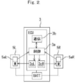
腰当て部材3には、図2に示すように、制御部3a、通信部3b、電動モータ駆動用のモータドライバ3cL,3cR等を含む電子制御ユニットECUとバッテリBATTとが内蔵されている。なお、モータドライバに代えてインバータを用いてもよい。また、腰当て部材3の背部外面には、電源スイッチ(図示せず)が設けられている。
図1に示すように、補助装置1は、電子制御ユニットECUにより駆動、制御される、左右の各上体側フレーム4L,4Rの先端部に取付けられた回転駆動力発生装置であるアクチュエータ5L,5Rを備えている。補助装置1は、アクチュエータ5L,5Rの出力回転軸が利用者Pの股関節部の略側方位置に配置されるように利用者Pに装着される。なお、図1では、利用者Pの右側の上体側フレーム4R及びアクチュエータ5Rは、利用者Pの背後に隠れているため図示されていない。
図2に示すように、補助装置1はさらに、電子制御ユニットECUに接続され、かつ利用者Pの運動状態量を検出するための検出器としてのアクチュエータ5L,5Rの角度検出器5aL,5aRを備えている。各角度検出器52は、左右の各上体側フレーム4に対する脚側フレーム8のピッチ方向(利用者Pの軸周りF方向又はE方向)の回転角を、利用者Pの各股関節の変位量(上体に対する各脚の大腿部のピッチ方向の回転角)を示すものとして検出するものであり、例えば各アクチュエータ5に組付けられている(図1を参照)。該角度検出器52は、例えばロータリーエンコーダ、レゾルバ、ポテンショメータ等により構成され得る。
図1に示すように、補助装置1は、アクチュエータ5L,5Rに取付けられた脚側フレーム8L,8Rを備えている。脚側フレーム8L,8Rは、その円環端部がアクチュエータ5L,5Rの出力軸とトルク伝達関係を維持してそれぞれ着脱可能に連結されている。
脚側フレーム8L,8Rは、炭素繊維強化プラスチック等の高剛性を有する材料により構成され、利用者Pの股関節部の外側の円環端部から利用者Pの大腿部前側へと太腿に沿って延びるように捩られた形状を有する。
脚側フレーム8L,8Rの円環端部の反対側の先端部(大腿部前側)には、脚当て部材7L,7Rが取り付けられている。脚当て部材7L,7Rは、強化プラスチック製で大腿前部の形状に合った湾曲形状を有する。
脚当て部材7L,7Rには、ベルト状の大腿取付け用部材6L,6Rが連結されている。大腿取付け用部材6L,6Rは、利用者Pの左右の各脚の大腿部の下部寄りの前面部に脚当て部材7L,7Rを当接された状態で保持する。
図2に示すように、電子制御ユニットECUにより駆動、制御される各アクチュエータ5は、例えば電動モータM等の回転型のアクチュエータにより構成される。各アクチュエータ5は、利用者Pの脚の股関節での屈曲動作又は伸展動作に伴い、当該アクチュエータ5と同じ側の上体側フレーム4に対して脚側フレーム8がピッチ方向に回転し得ると共に、該ピッチ方向の回転駆動力を脚側フレーム8に適宜、出力し得るように該脚側フレーム8に接続されている。なお、各アクチュエータ5と脚側フレーム8との間の動力伝達経路には、例えば減速機、クラッチ機構等の動力伝達要素を含み得る。
利用者Pの各脚の股関節での屈曲動作は、該脚の上端部の股関節の変位動作によって、該脚の大腿部が、利用者Pの上体(胴体)の体幹軸に対して前方側に傾いた状態(例えば図1の利用者Pの左側の脚の大腿部の傾き状態)になるように、上体に対してピッチ方向(利用者Pの軸周りF方向)に回転変位する動作である。
また、各脚の伸展動作は、該脚の上端部の股関節の変位動作によって、該脚の大腿部が、利用者Pの上体の体幹軸に対して後方側に傾いた状態(例えば図1の利用者Pの右側の脚の大腿部の傾き状態)になるように、上体に対してピッチ方向(利用者Pの軸周りE方向)に回転変位する動作である。
各アクチュエータ5から脚側フレーム8に回転駆動力を出力することによって、その回転駆動力が該脚側フレーム8と、脚当て部材7又は取付け用部材6とを介して該アクチュエータ5と同じ側の脚の大腿部に伝達されるようになっている。これにより、利用者Pの各脚股関節での屈曲動作又は伸展動作を補助する補助力を、該脚と同じ側のアクチュエータ5から該脚の大腿部に付与することが可能となっている。すなわち、補助装置1は、利用者Pの歩行運動における左右の脚の股関節での屈曲動作F又は伸展動作Eを補助する補助力を該脚の大腿部に付与することが可能な装置である。
図2に示すように、電子制御ユニットECUは、角度検出器5aL,5aRが検出した回転角情報を、通信部3bを介して補助装置コントローラ20へ送信する。これにより、補助装置1は、自身のアクチュエータ回転動作を計測して送信する計測送信手段として機能する。すなわち、補助装置1は、角度検出器5aL,5aRからの出力信号を補助装置コントローラ20へ送信可能な測定装置として機能する。
[電子制御ユニット]
補助装置1の電子制御ユニットECUは、図示しないが、CPU(Central Processing Unit)、ROM(Read Only Memory)、RAM(Random Access Memory)等により構成されるマイクロコンピュータである制御部3aと、通信部3bと、電動モータ駆動用のモータドライバ3cL,3cRとを含む。制御部3aは角度検出器5aL,5aRからの出力信号及び補助装置コントローラ20からの指令信号(設定信号)に基づいて、適宜メモリから読み出したプログラムにしたがって演算処理を実行する。これにより、制御部3aは、共通電源のバッテリBATTから電圧調整された電力が供給されるアクチュエータ5L,5Rの動作をモータドライバ3cL,3cRを介してそれぞれ制御する。
補助装置1の電子制御ユニットECUは、図示しないが、CPU(Central Processing Unit)、ROM(Read Only Memory)、RAM(Random Access Memory)等により構成されるマイクロコンピュータである制御部3aと、通信部3bと、電動モータ駆動用のモータドライバ3cL,3cRとを含む。制御部3aは角度検出器5aL,5aRからの出力信号及び補助装置コントローラ20からの指令信号(設定信号)に基づいて、適宜メモリから読み出したプログラムにしたがって演算処理を実行する。これにより、制御部3aは、共通電源のバッテリBATTから電圧調整された電力が供給されるアクチュエータ5L,5Rの動作をモータドライバ3cL,3cRを介してそれぞれ制御する。
補助装置1の制御部3aは、通信部3bを介した補助装置コントローラ20(図1)からの指令により、アクチュエータ5L,5Rの回動角、回動速度、屈曲トルク、伸展トルク、タイミング等の歩行補助の制御パラメータが書き換え可能に設定され、角度検出器5aL,5aRからの角度情報を用いてアクチュエータ5L,5Rの回転角をフィードバック制御する。制御部3aは、受信した当該制御パラメータに基づく指令ダイヤグラムに応じてアクチュエータ5L,5Rの回転駆動力を制御する。
[補助装置コントローラ]
補助装置コントローラ20は、図示しないが、CPU(Central Processing Unit)、ROM(Read Only Memory)、RAM(Random Access Memory)、SSD(solid state drive)、フラッシュメモリ等により構成され、タッチパネル22と、Wi-FiやBluetooth(登録商標)等の通信部(図示せず)を備える一般的な例えば、タブレットタイプのパーソナルコンピュータ(タブレットPC)、タッチパネル付きのノートタイプPCである。補助装置コントローラ20は、CPUが、ROMやSSDに記憶されたオペレーティングシステムや各種プログラムを読み出し実行することにより、補助装置1へ制御パラメータ情報(指令ダイヤグラム)を提供する制御パラメータ情報提供装置(指令ダイヤグラムを取得する取得部、当該取得された指令ダイヤグラムを表示しかつ前記指令ダイヤグラムの変更に関するタッチ入力を受け付けるタッチパネルを制御する表示制御部、及び、前記指令ダイヤグラムを前記タッチ入力に応じて変更する変更部)として機能する。
補助装置コントローラ20は、図示しないが、CPU(Central Processing Unit)、ROM(Read Only Memory)、RAM(Random Access Memory)、SSD(solid state drive)、フラッシュメモリ等により構成され、タッチパネル22と、Wi-FiやBluetooth(登録商標)等の通信部(図示せず)を備える一般的な例えば、タブレットタイプのパーソナルコンピュータ(タブレットPC)、タッチパネル付きのノートタイプPCである。補助装置コントローラ20は、CPUが、ROMやSSDに記憶されたオペレーティングシステムや各種プログラムを読み出し実行することにより、補助装置1へ制御パラメータ情報(指令ダイヤグラム)を提供する制御パラメータ情報提供装置(指令ダイヤグラムを取得する取得部、当該取得された指令ダイヤグラムを表示しかつ前記指令ダイヤグラムの変更に関するタッチ入力を受け付けるタッチパネルを制御する表示制御部、及び、前記指令ダイヤグラムを前記タッチ入力に応じて変更する変更部)として機能する。
タッチパネル22は、液晶パネルのような表示装置とタッチパッドのような位置入力装置を組み合わせた電子部品であり、画面上の表示を押すことで機器を操作する入力装置である。補助装置コントローラ20は、図示しないが、出力部として映像を表示するタッチパネル22の他に音を発するスピーカを備える。なお、補助装置コントローラ20は、補助装置1から送信された当該計測結果を取得して参照情報として又は変更可能な指令ダイヤグラムとしてタッチパネル22に表示させることができる。
[データベース装置]
データベース装置DBは、図示しないが、CPU(Central Processing Unit)、ROM(Read Only Memory)、RAM(Random Access Memory)、SSD(solid state drive)又はHDD(hard disk drive)、フラッシュメモリ等により構成され、Wi-FiやBluetooth(登録商標)等の無縁又は有線の通信部を備える一般的な例えば、サーバコンピュータ(PC)である。データベース装置DBは、CPUが、ROMやSSDに記憶されたオペレーティングシステムや各種プログラムを読み出し実行することにより、補助装置コントローラ20に対して入力された制御パラメータ情報(指令ダイヤグラム)の送受信と記憶を実行するサーバ装置として機能する。データベース装置DBは、補助装置コントローラ20の通信部と間にて少なくとも前記指令ダイヤグラムの通信が可能であって、当該通信の結果として前記指令ダイヤグラムを蓄積する。データベース装置DBは、蓄積された指令ダイヤグラムの情報に基づき統計処理を行い、後述のリコメンドダイヤグラムを生成して補助装置コントローラ20に提供する。
データベース装置DBは、図示しないが、CPU(Central Processing Unit)、ROM(Read Only Memory)、RAM(Random Access Memory)、SSD(solid state drive)又はHDD(hard disk drive)、フラッシュメモリ等により構成され、Wi-FiやBluetooth(登録商標)等の無縁又は有線の通信部を備える一般的な例えば、サーバコンピュータ(PC)である。データベース装置DBは、CPUが、ROMやSSDに記憶されたオペレーティングシステムや各種プログラムを読み出し実行することにより、補助装置コントローラ20に対して入力された制御パラメータ情報(指令ダイヤグラム)の送受信と記憶を実行するサーバ装置として機能する。データベース装置DBは、補助装置コントローラ20の通信部と間にて少なくとも前記指令ダイヤグラムの通信が可能であって、当該通信の結果として前記指令ダイヤグラムを蓄積する。データベース装置DBは、蓄積された指令ダイヤグラムの情報に基づき統計処理を行い、後述のリコメンドダイヤグラムを生成して補助装置コントローラ20に提供する。
[指令ダイヤグラム]
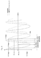
図3は、指令ダイヤグラムの一例としてアクチュエータ5L,5Rの回転駆動力となるアシストトルクの変化を示すグラフ(縦軸に脚体角度を横軸に時刻を示す)である。
図3は、指令ダイヤグラムの一例としてアクチュエータ5L,5Rの回転駆動力となるアシストトルクの変化を示すグラフ(縦軸に脚体角度を横軸に時刻を示す)である。
ここで、利用者Pが図3に破線で示されているように左右それぞれの脚体角度φ(測定値)を周期的に変化させながら歩行している状況を考える。この状況で所定の特性関数Fにしたがう制御部3aにより、図3に一点鎖線で示されているようにアシストトルク(補助力)が利用者Pに作用するようにアクチュエータ5L,5Rの動作が制御される。トルクFは、脚体角度φを上昇させるように利用者Pに作用する場合には「正」として定義される一方、脚体角度φを低下させるように利用者Pに作用する場合には「負」として定義される。
すなわち、この状況においては第1アシスト期間→第2アシスト期間→第3アシスト期間→第4アシスト期間の順序で当該4つの期間が周期的に変遷する。第iアシスト期間(i=1~4)とは、測定値(φ)が第iアシスト定義域に属する期間を意味する。
「第1アシスト期間」においては、アシストトルクが0からその極小値Fminまで連続的に低下するように制御される(図3参照)。すなわち、利用者Pが立脚状態の脚体を支えとして上体を前方に並進させるような上体及び当該脚体の相対運動に対する補助力が、最初は0で、その後徐々に強くなるような変化形態で利用者Pに与えられる。
「第2アシスト期間」においては、アシストトルクがその極小値Fminから0まで連続的に上昇するように制御される(図3参照)。すなわち、利用者Pが立脚状態の脚体を支えとして上体を前方に並進させるような上体及び当該脚体の相対運動に対する補助力が、最初は強く、その後徐々に弱くなって最後は0になるような変化形態で利用者Pに与えられる。
「第3アシスト期間」においては、アシストトルクが0からその極大値Fmaxまで連続的に上昇するように制御される(図3参照)。すなわち、利用者Pが主に遊脚状態の脚体を前方に並進させるような上体及び当該脚体の相対運動に対する補助力が、最初は0で、その後徐々に強くなるような変化形態で利用者Pに与えられる。
[補助装置コントローラの動作]
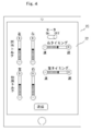
図3に示すような一点鎖線で示されているようにアシストトルク(補助力)の指令ダイヤグラムの変更は、図4に示す補助装置コントローラ20のタッチパネル22上に表示される設定ダイヤグラム(補助装置1の制御パラメータを設定する画面)のキー表示の操作によって行われる。
図3に示すような一点鎖線で示されているようにアシストトルク(補助力)の指令ダイヤグラムの変更は、図4に示す補助装置コントローラ20のタッチパネル22上に表示される設定ダイヤグラム(補助装置1の制御パラメータを設定する画面)のキー表示の操作によって行われる。
例えば、図4に示す設定ダイヤグラム画面は、図3に示す指令ダイヤグラムと同時にタッチパネル22に表示される。タッチパネル22上の「屈曲トルク」「伸展トルク」の中間タブを上下にスワイプしたり、「右タイミング」「左タイミング」の中間タブを左右にスワイプしたりすることにより、タッチ入力で行うことができる。この中間タブへのタッチ入力に応じて、図3に示した指令ダイヤグラムが変化する。
当該指令ダイヤグラムの変更の確認は、図3に示すアシストトルク(補助力)の指令ダイヤグラムの目視により行われる。指令ダイヤグラムの変更の完了後は、キー表示「送信」をタップして、指令ダイヤグラムの情報を補助装置1へ送信する。なお、図3に示した指令ダイヤグラムをタッチ入力で変化させた場合には、図4に示す設定ダイヤグラム画面のキー表示も変化する。
図4に示す設定ダイヤグラム画面のみによる制御パラメータ変更操作は煩雑であることを解消するため、本実施例においては、補助装置コントローラ20の制御部は、タッチパネル22に指令ダイヤグラムを表示させ、これを変更した際に、タッチパネル22に当該変更後の指令ダイヤグラムを表示して、前記変更後の指令ダイヤグラムに基づき補助装置コントローラ20の通信部を介して補助装置1を制御する。
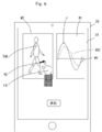
例えば、図5に示すように、補助装置コントローラ20の制御部は、タッチパネル22において前記指令ダイヤグラムを表示させるウィンドウを例えば2つW1、W2を生成し、該ウィンドウ中でのみ前記指令ダイヤグラムの変更を許容する。そして、補助装置コントローラ20の制御部は、ウィンドウW1では補助装置1に推奨される動作指令の時系列を表わす波形WVのリコメンドダイヤグラムをタッチパネル22に表示させ、ウィンドウW2では、前記指令ダイヤグラムの変更のための疑似利用者の3次元モデルTHD(ベクトルVCを含むリコメンドダイヤグラム)をタッチパネル22に表示させる。
これにより、利用者を補助する理学療法士や看護士等(以下、療法士という)が指により波形又はベクトルの前記指令ダイヤグラムを直接変更(スワイプ等で)できるようになり、補助装置コントローラ20の制御部はタッチ入力としてタッチパネル22における指の接触ポイントの位置又は軌道を検知できる。
具体的には、療法士は、指FGにより3次元モデルTHDのベクトルVCの先端に触れて、それをスワイプすることにより、当該部分のパラメータ値を変化させたり当該部分が到来する時刻を変化させたりすることも可能である。また、図5に示す画面上において波形WVのピーク部分Pにタッチし、それをスワイプすることでピーク値またはピークの時刻を変更することが可能である。例えば、ピーク部分Pをタッチして上下にスワイプすることで、ピーク値が変更可能であり、ピーク部分Pをタッチして左右にスワイプすることでピークの時刻を変更することが可能である。また、波形WVの任意の部分をタッチして上下左右にスワイプすることで、当該部分の値を変化させたり当該部分が到来する時刻を変化させたりすることも可能である。
このように、補助装置コントローラ20のタッチパネル画面を介して、療法士による指令ダイヤグラムの入力を容易に受け付け、その記録が行うことができる。この際、ウィンドウごとに、変更前後の形形態WVの前記指令ダイヤグラムと変更前後の疑似利用者のベクトルVCの3次元モデルとを同時にタッチパネル22に表示させることもできる。指令ダイヤグラムの変更の完了後は、キー表示「送信」をタップして、指令ダイヤグラムの情報を補助装置1とデータベース装置DBへ送信する。
補助装置1は自身の動作を計測して送信する故に、補助装置コントローラ20の制御部は、補助装置コントローラ20の通信部を介して当該計測結果を取得して参照情報(図5における破線の波形WV2)としてタッチパネル22に表示させる。
補助装置コントローラ20の制御部は、タッチパネル22に入力する入力者(療法士)の登録された経験レベルに応じて前記指令ダイヤグラムの変更の許容範囲を制限することができる。
本実施例では、補助装置1の通信部3bが補助装置コントローラ20より受信する信号は、補助装置1の個体識別情報に関する信号を含んでいる。
また、補助装置1の通信部3bが補助装置コントローラ20より受信する信号は、制御部3aによる歩行補助の制御パラメータである指令ダイヤグラムに関する信号を含んでおり、制御部3aは通信部3bが補助装置コントローラ20より受信した信号によって指令ダイヤグラムを書き換え可能に設定される。
補助装置コントローラ20は、療法士によって管理され、自身の指令ダイヤグラム設定編集画面において、脚側フレーム8L,8Rの回動角、回動速度等の歩行補助の指令ダイヤグラムを補助装置1の利用者P)毎に個別に変更可能に設定でき、設定した指令ダイヤグラムを利用者P毎に記憶し、利用者Pをキーとして指令ダイヤグラムを読み出し、読み出された指令ダイヤグラムを通信部3bへ送信する。
補助装置コントローラ20は、補助装置コントローラ20と通信可能で接続されたデータベース装置DBに格納されている利用者P毎の指令ダイヤグラムを受信し、それを記憶してもよい。
これにより、効果的な歩行リハビリテーションのために、療法士による歩行補助の指令ダイヤグラムの適切な入力が可能となり、指令ダイヤグラムの情報の蓄積が期待できる。
なお、補助装置1は、上記実施例の両脚用のものには限定されず、利用者Pの歩行運動における左又は右の片脚の股関節近傍にのみアクチュエータを設けたものであってもよい。
1…補助装置、ECU…電子制御ユニット、20…補助装置コントローラ、…バッテリBATT、3cL,3cR…モータドライバ、3a…制御部、3b…通信部、DB…データベース装置。
Claims (11)
- 人の動作を補助する補助装置への動作指令を時系列に沿って示すダイヤグラムである指令ダイヤグラムを取得する取得部と、
当該取得された指令ダイヤグラムを表示しかつ前記指令ダイヤグラムの変更に関するタッチ入力を受け付けるタッチパネルを制御する表示制御部と、
前記指令ダイヤグラムを前記タッチ入力に応じて変更する変更部と、
を有することを特徴とする補助装置コントローラ。 - 前記表示制御部は、前記タッチ入力として前記タッチパネルにおける接触ポイントの位置又は軌道を検知し、前記変更部は当該検知結果に基づいて前記指令ダイヤグラムを変更することを特徴とする請求項1に記載の補助装置コントローラ。
- 前記取得部は、前記補助装置に推奨される動作指令の時系列を表わす波形又はベクトルを含むリコメンドダイヤグラムを取得し、前記表示制御部は、前記タッチパネルに前記リコメンドダイヤグラムを表示させることを特徴とする請求項1又は2に記載の補助装置コントローラ。
- 前記表示制御部は、前記リコメンドダイヤグラムの前記波形又は前記ベクトルにおける前記接触ポイントの位置又は軌道を検知し、前記変更部は当該検知結果に基づいて前記指令ダイヤグラムを変更することを特徴とする請求項3に記載の補助装置コントローラ。
- 前記取得部は、前記補助装置の過去の動作態様を、前記指令ダイヤグラムとして又は前記指令ダイヤグラムの変更に対する参照情報として取得し、前記表示制御部は、前記過去の動作態様を前記指令ダイヤグラムとして又は前記参照情報として前記タッチパネルに表示させることを特徴とする請求項1乃至4の何れか一項に記載の補助装置コントローラ。
- 前記取得部は、前記補助装置の制御パラメータを設定する設定ダイヤグラムを取得し、前記表示制御部は、前記設定ダイヤグラムを前記タッチパネルに表示させ、
前記変更部は、前記タッチ入力に応じて前記指令ダイヤグラム又は前記設定ダイヤグラムを変更すると共に、当該変更後の前記指令ダイヤグラム又は前記設定ダイヤグラムに連動して前記設定ダイヤグラム又は前記指令ダイヤグラムを変更することを特徴とする請求項5に記載の補助装置コントローラ。 - 前記表示制御部は、前記タッチパネルにおいて前記指令ダイヤグラムを表示させるウィンドウを生成し、前記変更部は該ウィンドウ中でのみ前記指令ダイヤグラムの変更を許容する
ことを特徴とする請求項1乃至6の何れか一項に記載の補助装置コントローラ。 - 前記変更部は、前記タッチパネルに入力する入力者の登録されたレベルに応じて前記指令ダイヤグラムの変更の許容範囲を制限することを特徴とする請求項1乃至7の何れか一項に記載の補助装置コントローラ。
- 前記表示制御部は、前記指令ダイヤグラムの変更があった場合、前記指令ダイヤグラムの変更の前後の疑似利用者の3次元モデルを同時に前記タッチパネルに表示させることを特徴とする請求項1乃至8の何れか一項に記載の補助装置コントローラ。
- 請求項3乃至9の何れか一項に記載の前記補助装置コントローラと、
前記補助装置コントローラの前記取得部と間にて少なくとも前記指令ダイヤグラムの通信が可能であって、当該通信の結果として前記指令ダイヤグラムを蓄積するデータベース装置と、を有することを特徴とする運動状態観測システム。 - 前記データベース装置は、蓄積された指令ダイヤグラムに基づき統計処理を行い、前記リコメンドダイヤグラムを生成して前記補助装置コントローラに提供することを特徴とする請求項10に記載の運動状態観測システム。
Applications Claiming Priority (2)
| Application Number | Priority Date | Filing Date | Title |
|---|---|---|---|
| JP2018-185553 | 2018-09-28 | ||
| JP2018185553 | 2018-09-28 |
Publications (1)
| Publication Number | Publication Date |
|---|---|
| WO2020066252A1 true WO2020066252A1 (ja) | 2020-04-02 |
Family
ID=69950391
Family Applications (1)
| Application Number | Title | Priority Date | Filing Date |
|---|---|---|---|
| PCT/JP2019/029089 Ceased WO2020066252A1 (ja) | 2018-09-28 | 2019-07-24 | 補助装置コントローラ及び運動状態観測システム |
Country Status (1)
| Country | Link |
|---|---|
| WO (1) | WO2020066252A1 (ja) |
Citations (6)
| Publication number | Priority date | Publication date | Assignee | Title |
|---|---|---|---|---|
| JP2007072518A (ja) * | 2005-09-02 | 2007-03-22 | Omron Corp | 制御装置のヒューマン・マシン・インタフェース装置 |
| JP2011177329A (ja) * | 2010-03-01 | 2011-09-15 | Toyota Motor Corp | 動作支援システム |
| JP2015058033A (ja) * | 2013-09-17 | 2015-03-30 | 株式会社安川電機 | 動作補助装置及び動作補助プログラム |
| WO2016038824A1 (ja) * | 2014-09-10 | 2016-03-17 | パナソニック株式会社 | 歩容データ管理システム、歩容データ管理方法、歩行支援装置、及び、サーバ |
| JP2017154210A (ja) * | 2016-03-02 | 2017-09-07 | パナソニック株式会社 | 動作支援装置、及び、動作支援システム |
| JP2017217039A (ja) * | 2016-06-02 | 2017-12-14 | 株式会社スペース・バイオ・ラボラトリーズ | 歩行動作補助装置 |
-
2019
- 2019-07-24 WO PCT/JP2019/029089 patent/WO2020066252A1/ja not_active Ceased
Patent Citations (6)
| Publication number | Priority date | Publication date | Assignee | Title |
|---|---|---|---|---|
| JP2007072518A (ja) * | 2005-09-02 | 2007-03-22 | Omron Corp | 制御装置のヒューマン・マシン・インタフェース装置 |
| JP2011177329A (ja) * | 2010-03-01 | 2011-09-15 | Toyota Motor Corp | 動作支援システム |
| JP2015058033A (ja) * | 2013-09-17 | 2015-03-30 | 株式会社安川電機 | 動作補助装置及び動作補助プログラム |
| WO2016038824A1 (ja) * | 2014-09-10 | 2016-03-17 | パナソニック株式会社 | 歩容データ管理システム、歩容データ管理方法、歩行支援装置、及び、サーバ |
| JP2017154210A (ja) * | 2016-03-02 | 2017-09-07 | パナソニック株式会社 | 動作支援装置、及び、動作支援システム |
| JP2017217039A (ja) * | 2016-06-02 | 2017-12-14 | 株式会社スペース・バイオ・ラボラトリーズ | 歩行動作補助装置 |
Similar Documents
| Publication | Publication Date | Title |
|---|---|---|
| US11771613B2 (en) | Robot system for active and passive upper limb rehabilitation training based on force feedback technology | |
| US8674838B2 (en) | Walking assist device | |
| CN102614066B (zh) | 一种提供主动辅助和被动拉伸的患肢训练装置及其控制方法 | |
| CN107961078B (zh) | 手术机器人系统及其手术器械 | |
| US8359123B2 (en) | Robotic system and training method for rehabilitation using EMG signals to provide mechanical help | |
| CN107361992B (zh) | 一种人体下肢运动助力装置 | |
| US20150148728A1 (en) | Isolated orthosis for thumb actuation | |
| WO2006080134A1 (ja) | 装着式動作補助装置及び制御用プログラム | |
| JP2005348779A (ja) | 運動機能回復訓練システム | |
| JP2018199205A (ja) | アシスト装置 | |
| JP6453190B2 (ja) | 歩数計測器、歩行補助装置及び歩数演算プログラム | |
| CN111081386A (zh) | 一种基于虚拟现实技术的医疗交互系统 | |
| CN116841396A (zh) | 基于振动和皮肤位移控制的触觉手套装置及渲染方法 | |
| KR20200082423A (ko) | 촉각 피드백이 가능한 가상현실 기반의 손 재활 시스템 | |
| JP2005006751A (ja) | 歩行訓練装置 | |
| KR20160141095A (ko) | 상지 재활 치료 시스템 | |
| WO2020066252A1 (ja) | 補助装置コントローラ及び運動状態観測システム | |
| CN116690567A (zh) | 一种基于拟人神经模型的下肢外骨骼驱动方法 | |
| JP2002263151A (ja) | 全方向移動型歩行介助装置 | |
| CN106333823A (zh) | 一种机器人 | |
| Wang et al. | Data glove control of robot hand with force telepresence | |
| CN204725501U (zh) | 体感机械臂舒适度检测装置 | |
| CN105056482B (zh) | 步态矫正传感反馈装置及系统 | |
| JP2011143002A (ja) | 歩行補助装置 | |
| TWI601526B (zh) | Lower limb rehabilitation device control method and the implementation of the method of lower limb rehabilitation device |
Legal Events
| Date | Code | Title | Description |
|---|---|---|---|
| 121 | Ep: the epo has been informed by wipo that ep was designated in this application |
Ref document number: 19865320 Country of ref document: EP Kind code of ref document: A1 |
|
| NENP | Non-entry into the national phase |
Ref country code: DE |
|
| 122 | Ep: pct application non-entry in european phase |
Ref document number: 19865320 Country of ref document: EP Kind code of ref document: A1 |
|
| NENP | Non-entry into the national phase |
Ref country code: JP |