WO2020065880A1 - 電力変換装置 - Google Patents
電力変換装置 Download PDFInfo
- Publication number
- WO2020065880A1 WO2020065880A1 PCT/JP2018/036114 JP2018036114W WO2020065880A1 WO 2020065880 A1 WO2020065880 A1 WO 2020065880A1 JP 2018036114 W JP2018036114 W JP 2018036114W WO 2020065880 A1 WO2020065880 A1 WO 2020065880A1
- Authority
- WO
- WIPO (PCT)
- Prior art keywords
- conversion device
- power conversion
- main body
- device main
- plate
- Prior art date
- Legal status (The legal status is an assumption and is not a legal conclusion. Google has not performed a legal analysis and makes no representation as to the accuracy of the status listed.)
- Ceased
Links
Images

Classifications
-
- H—ELECTRICITY
- H02—GENERATION; CONVERSION OR DISTRIBUTION OF ELECTRIC POWER
- H02M—APPARATUS FOR CONVERSION BETWEEN AC AND AC, BETWEEN AC AND DC, OR BETWEEN DC AND DC, AND FOR USE WITH MAINS OR SIMILAR POWER SUPPLY SYSTEMS; CONVERSION OF DC OR AC INPUT POWER INTO SURGE OUTPUT POWER; CONTROL OR REGULATION THEREOF
- H02M7/00—Conversion of AC power input into DC power output; Conversion of DC power input into AC power output
- H02M7/42—Conversion of DC power input into AC power output without possibility of reversal
- H02M7/44—Conversion of DC power input into AC power output without possibility of reversal by static converters
- H02M7/48—Conversion of DC power input into AC power output without possibility of reversal by static converters using discharge tubes with control electrode or semiconductor devices with control electrode
Definitions
- the present invention relates to a power converter, and more particularly, to a power converter having a mounting leg for mounting a power converter main body to an installation portion.
- Patent Document 1 discloses a motor drive drive unit (power supply) including a main circuit including a semiconductor module, a radiating fin thermally coupled to a control circuit and a main circuit component, and a blower fan for cooling the radiating fin.
- a conversion device is disclosed.
- mounting legs mounting legs for fixing the unit to a wall surface or the like are mounted on the front side and the rear side of the housing of the unit with screws.
- the conventional power conversion device as described in Patent Document 1 is installed in an environment (such as in the mountains) where a crane truck or the like for suspending the device cannot be used.
- the power converter may be separately provided (as a separate member) for the operator to hold the power converter. Then, the operator transports the power conversion device to the installation location while holding the grip portion, and then installs the power conversion device at the installation location.
- a power conversion device includes a power conversion device main body, a mounting leg for mounting the power conversion device main body on an installation portion, and a power conversion device main body. And an integrated member integrally formed with a gripping portion that is gripped by an operator.
- a mounting leg for mounting the power conversion device main body to the installation portion, and a grip portion that is gripped by an operator when transporting the power conversion device main body. are integrally formed. Accordingly, since it is not necessary to provide a gripping portion for gripping the power conversion device main body when the operator transports the power conversion device main body as a separate member from the mounting leg portion, it is possible for the operator to reduce the number of parts while maintaining the device. Can be provided.
- the integrated member is located on one side in the first direction of the in-plane direction that is horizontal when the power converter main body is transported with respect to the power converter main body.
- the gripping portion is an end of the one-piece end in the second direction orthogonal to the first direction of the in-plane direction in the integrated member. To the other end.
- the power conversion device main body and the installation portion face each other in a third direction orthogonal to the first direction and the second direction.
- the grip portion is provided on the power conversion device main body side of the integrated member in the third direction, and the mounting leg portion is opposite to the power conversion device main body side of the integrated member in the third direction. It is provided on the side.
- the power conversion device is arranged on the ground such that the grip portion is located on the upper side and the mounting leg portion is located on the lower side in the integrated member. .
- the gripping portion is located relatively on the upper side when the power converter is transported (before), so that the worker can easily grip the gripping portion (the worker).
- the power converter can be lifted (without increasing the burden on the power converter).
- the mounting leg is provided on the opposite side of the power conversion device main body side of the integrated member, when the power conversion device main body is installed on the installation portion, the power conversion device main body is connected via the integrated member. Can be easily installed in the installation section.
- the grip has a first hole into which a first fastening member for attaching the integrated member to the power conversion device main body is inserted.
- the mounting leg has a first hole as viewed from a third direction. At a position corresponding to the hole, a tool hole or a notch is provided for passing a tool for inserting and fastening the first fastening member into the first hole.
- the tool when attaching the integrated member to the power conversion device main body, the tool is passed through the tool hole or the notch from the side opposite to the power conversion device main body side in the third direction, The operation of inserting and fastening the first fastening member into the first hole provided in the gripper can be performed. As a result, even when there is no space for operating the tool from the first direction or the second direction, the tool can be easily operated from the third direction.
- the first fastening member can be easily fastened to the one hole.
- a second fastening member for attaching the power conversion device body to the installation portion is inserted into the attachment leg at a position different from the tool hole or the notch when viewed from the third direction.
- a second hole is provided.
- the second hole and the tool hole or the notch are provided at different positions (separately) when viewed from the third direction. Irrespective of the size of the tool that passes through the hole or the notch, it can be appropriately provided according to the size of the second fastening member inserted into the second hole.
- the integrated member includes a first plate-shaped portion provided along a surface of the power conversion device main body on the installation portion side in an installed state, and a central portion side of the power conversion device main body in a first direction of the first plate-shaped portion. Is a second plate-shaped portion provided to extend from the opposite end in a direction away from the power conversion device main body in the third direction, and an end of the second plate-shaped portion opposite to the first plate-shaped portion.
- the first plate-shaped portion since the first plate-shaped portion is provided along the surface on the installation portion side in the installed state of the power converter main body, the first plate-shaped portion allows the power converter main body to be an integral member. On the side, the integrated member can be easily fixed to the power converter main body.
- a second plate-shaped portion extending in the third direction as viewed from the second direction, and a protruding portion projecting from the end of the second plate-shaped portion in the first direction toward the center of the power conversion device main body,
- the L-shape allows the operator to easily grip the L-shaped portion formed by the second plate-shaped portion and the protruding portion from one side in the first direction of the integrated member.
- the outer surface of the corner portion of the boundary between the second plate-shaped portion and the protruding portion, and the end of the protruding portion opposite to the second plate-shaped portion are viewed from the second direction. , Having a round cross-sectional shape.
- the integrated member is a central portion of the power converter main body in the first direction of the first plate-shaped portion.
- a third plate-shaped portion provided to extend from the end on the side in the third direction in a direction away from the power conversion device main body in the third direction, longer than the second plate-shaped portion, and the first plate-shaped portion of the third plate-shaped portion
- a second end extending from the end opposite to the central portion of the power conversion device main body in the first direction in a direction substantially parallel to a surface on the installation portion side in the installation state of the power conversion device main body.
- a four-plate portion is provided to extend from the end on the side in the third direction in a direction away from the power conversion device main body in the third direction, longer than the second plate-shaped portion, and the first plate-shaped portion of the third plate-shaped portion
- a second end extending from the end opposite to the central portion of the power conversion device main body in the first direction in a direction substantially parallel to a surface on the installation portion side in the installation state of the power conversion device main body
- the fourth plate-shaped portion provided to extend substantially parallel to the surface of the power conversion device main body is provided along the installation portion when the power conversion device main body is installed, With the fourth plate-shaped portion, the integrated member can be easily fixed to the installation portion on the side opposite to the power conversion device main body side of the integrated member. Also, the third plate-shaped portion is located at the center of the power converter main body in the first direction of the integrated member, and is connected to the power converter main body from the end of the first plate-shaped portion provided on the power converter main body.
- the first plate-shaped portion is positioned more than the third plate-shaped portion. It is possible to prevent the power conversion device from entering the central portion of the main body in the direction. As a result, if, for example, a heat radiating portion or the like for radiating heat generated from the power conversion device main body or the like is provided on the central portion side of the power conversion device main body in the first direction, the operator may erroneously become hot. It is possible to suppress contact with the heat radiating portion or the like.
- the inner surface of the boundary between the third plate-shaped portion and the fourth plate-shaped portion has a round cross-sectional shape when viewed from the second direction.
- the thickness of the corner at the boundary between the third plate-shaped portion and the fourth plate-shaped portion can be made relatively large.
- the concentration of stress acting on the corner at the boundary between the third and fourth plate portions can be reduced, and the mechanical strength at the corner at the boundary between the third and fourth plate portions can be reduced. Can be improved.
- the integrated member includes the third plate-shaped portion
- a reactor provided between the power conversion device main body and the installation portion in the installed state of the power conversion device, and a reactor connected to the power conversion device main body
- a cover member for covering the reactor from the second direction side, and the third plate-shaped portion is provided with a third hole for inserting the third fastening member from the second direction to attach the cover member.
- the third plate-shaped portion has a portion formed to be thicker than other portions.
- the third hole for attaching the cover member can be easily provided in a portion formed to be thicker than the other portions of the third plate-shaped portion.
- the integrated member is integrally formed of an extruded aluminum product.
- a desired cross-sectional shape can be easily formed from an extruded aluminum product having good workability. It is possible to easily and integrally form a grip portion that requires a shape that can be easily gripped.
- aluminum can form an oxide film (alumina) by itself and ensure corrosion resistance without applying a film treatment, by making the integral member made of aluminum, coating treatment such as painting to ensure corrosion resistance can be performed. The step of applying to the integral member can be omitted.
- the power conversion device main body includes an inverter unit for converting power generated by sunlight.
- an inverter unit for converting power generated by sunlight is provided with a grip unit for an operator to grip the device while suppressing an increase in the number of components. It is particularly effective to apply a configuration that can perform the following.
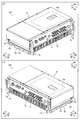
- FIG. 3 is a perspective view of an integrated member in the power converter according to one embodiment of the present invention.
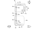
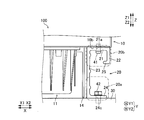
- FIG. 3 is a side view of an integrated member in the power converter according to one embodiment of the present invention. It is a figure showing the state where the power converter by one embodiment of the present invention was installed in the installation part.
- the power conversion device 100 includes a power conversion device main body 10, a reactor 11, a cover member 12, a protection plate 13, cooling fins 14 (see FIG. 4), an integrated member 20, Is provided.
- an inverter unit 10a including a main circuit including a semiconductor module, a control circuit, and the like is housed.
- the power converter 100 is a PCS (Power Conditioning System) for photovoltaic power generation. That is, the inverter unit 10a is a circuit for converting DC power generated by sunlight into AC.
- PCS Power Conditioning System
- the power conversion device 100 When the power conversion device 100 is installed in the mountains or the like, the power conversion device 100 is configured to be carried by a worker while being carried, and then installed in the installation section 30 (see FIG. 4).
- the horizontal in-plane directions are defined as X and Y directions
- the vertical direction orthogonal to the X and Y directions is defined as Z direction.
- the upper direction (upper side) and the lower direction (lower side) when transporting the power converter 100 are referred to as a Z1 direction (Z1 side) and a Z2 direction (Z2 side), respectively.
- the X direction, the Y direction, and the Z direction are examples of the “first direction”, the “second direction”, and the “third direction”, respectively, in the claims.
- the power conversion device main body 10 is formed in a substantially rectangular parallelepiped shape. On the Y2 side of the power conversion device main body 10, connectors for connecting cables and the like are provided. The power conversion device main body 10 is arranged on the Z1 side of the power conversion device 100. In addition, as shown in FIG. 4, in the installation state where the power conversion device main body 10 is installed with respect to the installation portion 30, the power conversion device main body 10 and the installation portion 30 are configured to face each other in the Z direction. I have.
- the reactor 11 is connected to the power conversion device main body 10.
- the reactor 11 is provided on the Z2 side of the power conversion device main body 10.
- reactor 11 is provided between power conversion device main body 10 and installation portion 30 when power conversion device 100 is installed.
- the cover member 12 is configured to cover the reactor 11 from the Y direction side. With the cover member 12, it is possible to prevent the operator from accidentally coming into contact with the reactor 11 that has become hot during operation of the power conversion device main body 10 (the inverter unit 10a) from the Y direction side.
- the protection plate 13 is attached to the X1 end and the Y2 side surface of the power conversion device main body 10, and the X2 side end and the Y2 side surface.
- the protection plate 13 is formed so as to protrude more to the Y2 side than the connectors provided on the Y2 side surface of the power conversion device main body 10.
- the protect plate 13 can protect the connectors from touching an object (such as the ground) when the power converter 100 is disposed with the Y2 side facing down during work or the like.
- the cooling fins 14 are provided to radiate heat generated from the power conversion device main body 10 (the inverter unit 10a).
- the cooling fins 14 are provided on the Z2 side of the power conversion device main body 10.
- the cooling fins 14 are provided between the power conversion device main body 10 and the installation portion 30 when the power conversion device 100 is installed.
- the cooling fins 14 are provided closer to the center of the power conversion device main body 10 (X1 side) than the integrated member 20 in the X direction.
- the integrated member 20 is positioned at one end (X1 side) and the other side (X2 side) in the X direction with respect to the power conversion device main body 10. Is provided at each end.
- the integrated member 20 provided at one end (X1 side) in the X direction and the integrated member 20 provided at the other end (X2 side) in the X direction are symmetrical to each other when viewed from the Y direction. It is configured to have a simple shape.
- the integrated member 20 is provided on the Z2 side of the power conversion device main body 10. That is, the integrated member 20 is configured to be disposed between the power conversion device main body 10 and the installation unit 30 when the power conversion device main body 10 is installed in the installation unit 30.
- 2 to 4 show the integral member 20 provided on the X2 side of the power converter 100.
- the integrated member 20 includes a mounting leg portion 20 a for mounting the power conversion device main body 10 to the installation portion 30, and an operator when transporting the power conversion device main body 10.
- the gripper 20b for gripping is integrally formed.
- the integral member 20 is integrally formed of an extruded aluminum product.
- the grip 20b is provided so as to extend from one end (Y1 side) in the Y direction to the other end (Y2 side) in the integrated member 20.
- the grip 20b is provided on the power conversion device main body 10 side (Z1 side) of the integrated member 20 in the Z direction.
- the mounting leg portion 20a is provided on the opposite side (Z2 side) of the integrated member 20 from the power conversion device main body 10 side (Z1 side) in the Z direction.
- the integrated member 20 includes a first plate-shaped portion 21, a second plate-shaped portion 22, a third plate-shaped portion 23, a fourth plate-shaped portion 24, and a protruding portion 25.
- the grip portion 20b is disposed on the Z1 side of the integrated member 20, and includes a first plate-like portion 21, a second plate-like portion 22, a projecting portion 25, and a third plate-like portion 23 on the Z1 side. , Is composed of.
- the mounting leg portion 20a is formed by a Z2 side portion of the third plate portion 23, the third plate portion 23, and the fourth plate portion 24, which are disposed on the Z2 side of the integrated member 20. It is configured.
- the first plate-shaped portion 21 is provided along the surface 10 b on the installation section 30 side (Z2 side) in the installation state of the power conversion device main body 10.
- the first plate portion 21 has a first hole 21a formed therein.
- the first hole 21a is a through hole into which the first fastening member 41 for fixing the power conversion device main body 10 and the first plate-shaped portion 21 is inserted.
- the first fastening member 41 is, for example, a screw. That is, in the present embodiment, the grip portion 20b is provided with the first hole portion 21a into which the first fastening member 41 for attaching the integrated member 20 to the power conversion device main body 10 is inserted.
- the second plate-like portion 22 extends from the end (X2 direction) opposite to the center portion (X1 direction) of the power converter main body 10 in the X direction of the first plate-like portion 21. It is provided so as to extend in a direction away from the power conversion device main body 10 in the Z direction (Z2 direction).
- the protruding portion 25 extends from the end (Z2 side) of the second plate-shaped portion 22 opposite to the first plate-shaped portion 21 to the center portion side (X2 side) of the power conversion device main body 10 in the X direction. It is provided so as to protrude with a length shorter than the shape portion 21.
- the portion 25a has a round cross-sectional shape when viewed from the Y direction.
- the third plate-shaped portion 23 is separated from the power conversion device main body 10 in the Z direction (Z2 direction) from the end of the first plate-shaped portion 21 on the center side (X1 direction) of the power conversion device main body 10 in the X direction. ) Is provided so as to extend longer than the second plate-shaped portion 22.
- the fourth plate-shaped portion 24 is located at the center of the power conversion device main body 10 in the X direction from the end (Z2 side) of the third plate-shaped portion 23 opposite to the first plate-shaped portion 21 (Z1 side).
- the power converter main body 10 is provided so as to extend substantially parallel to the surface 10b on the installation section 30 side (Z2 side) in the installed state.
- the surface C2a inside the corner portion C2 of the boundary between the third plate-shaped portion 23 and the fourth plate-shaped portion 24 has a round cross-sectional shape when viewed from the Y direction.
- the fourth plate-shaped portion 24 (the mounting leg 20a) is provided with a tool hole 24a and a notch 24b.
- the tool hole 24a and the notch 24b are provided at positions (overlapping positions) corresponding to the first holes 21a when viewed from the Z direction.
- the tool hole 24a and the notch 24b allow a tool (not shown) for fastening the first fastening member 41 to be inserted from the Z2 side when the first fastening member 41 is inserted into the first hole 21a and fastened.
- a second hole 24c is formed in the fourth plate-like portion 24 (the mounting leg 20a) at a position different from the tool hole 24a and the notch 24b when viewed from the Z direction.
- the second hole 24c is a through hole into which the second fastening member 42 for fixing the installation portion 30 and the fourth plate-shaped portion 24 is inserted.
- the second fastening member 42 is, for example, a bolt.
- the third plate-like portion 23 inserts the third fastening member 43 (see FIG. 1) from the Y direction to attach the cover member 12 (see FIG. 1).
- the third plate portion 23 has a portion formed to be larger than the thickness of the other portion as viewed from the Y direction so as to provide the third hole portion 23b for the third plate portion 23b.
- the third plate-shaped portion 23 is provided with a plurality (three) of tap seats 23 a formed to be thicker than other portions of the third plate-shaped portion 23.
- a third hole 23b is formed in the tap seat 23a.
- the third hole 23b is provided for inserting the third fastening member 43 (see FIG. 1) from the Y2 direction.
- the protection plate 13 and the cover member 12 are fixed to the integrated member 20 by the third fastening member 43.
- the mounting leg portion 20a for mounting the power conversion device main body 10 to the installation portion 30 and the grip portion 20b that is gripped by an operator when transporting the power conversion device main body 10 includes: It is formed integrally. Accordingly, since it is not necessary to provide the gripping portion 20b for gripping the power conversion device main body 10 when the operator transports the power conversion device main body 10 as a separate member from the mounting leg portion 20a, it is possible to suppress an increase in the number of parts while performing the work. A gripper 20b for a person to grip the device can be provided.
- the integrated member 20 is moved relative to the power conversion device main body 10 in the first direction (in the in-plane direction that is horizontal when the power conversion device main body 10 is transported). It is provided at one end (X1 side) and the other end (X2 side) in the (X direction). Further, in the integrated member 20, the grip portion 20b is moved from one end (Y1 side) in the second direction (Y direction) perpendicular to the first direction (X direction) of the in-plane directions to the other side (Y1 side). (Y2 side). Thus, the operator can grip any part of the integrated member 20 from the end on the one side (Y1 side) in the second direction (Y direction) to the end on the other side (Y2 side). .
- the power conversion device main body 10 and the installation portion 30 are moved in the first direction (X direction). And a third direction (Z direction) orthogonal to the second direction (Y direction). Then, the grip portion 20b is provided on the power converter main body 10 side (Z1 side) of the integrated member 20 in the third direction (Z direction), and the mounting leg portion 20a is moved in the third direction (Z direction).
- the body member 20 is provided on the side (Z2 side) opposite to the power conversion device main body 10 side (Z1 side).
- the gripper 20b is located relatively above, so that the worker can easily grip the gripper 20b (the burden on the worker is reduced).
- the power conversion device 100 can be lifted (while suppressing growth).
- the mounting leg portion 20a is provided on the opposite side (Z2 side) of the integrated member 20 from the power conversion device main body 10 side (Z1 side)
- the power conversion device main body 10 is installed on the installation section 30. In this case, the power conversion device main body 10 can be easily installed on the installation section 30 via the integrated member 20.
- the first hole 21a into which the first fastening member 41 for attaching the integrated member 20 to the power conversion device main body 10 is inserted is provided in the grip portion 20b.
- a tool for inserting the first fastening member 41 into the first hole 21a and fastening the mounting leg 20a at a position corresponding to the first hole 21a when viewed from the third direction (Z direction). Is provided with a tool hole 24a and a notch 24b through which the hole passes.
- the tool hole is formed from the side (Z2 side) opposite to the power conversion device main body 10 side (Z1 side) in the third direction (Z direction).
- the power conversion device main body 10 is mounted on the mounting leg 20a at a position different from the tool hole 24a and the notch 24b when viewed from the third direction (Z direction).
- a second hole 24c into which the second fastening member 42 for attaching the second mounting member 30 to the installation portion 30 is provided.
- the second hole 24c and the tool hole 24a and the notch 24b are provided at different positions (separately) when viewed from the third direction (Z direction), so that the size of the second hole 24c is large. This can be appropriately provided according to the size of the second fastening member 42 inserted into the second hole 24c, regardless of the size of the tool passing through the tool hole 24a and the notch 24b. .
- the integrated member 20 includes the first plate-shaped portion 21, the second plate-shaped portion 22, and the protruding portion 25. Then, the first plate-shaped portion 21 is provided along the surface 10 b on the installation section 30 side in the installation state of the power conversion device main body 10. In addition, the second plate-like portion 22 is moved in the third direction (Z direction) from the end of the first plate-like portion 21 in the first direction (X direction) opposite to the center portion side of the power conversion device main body 10. It is provided so as to extend in a direction away from the power conversion device main body 10 (Z2 direction).
- the protruding portion 25 is placed in the first plate-like shape from the end of the second plate-like portion 22 opposite to the first plate-like portion 21 toward the center of the power conversion device main body 10 in the first direction (X direction). It is provided so as to project with a shorter length than the portion 21.
- the first plate-shaped portion 21 is provided along the surface 10 b on the installation section 30 side in the installed state of the power conversion device main body 10, so that the power conversion of the integrated member 20 is performed by the first plate-shaped portion 21.
- the integrated member 20 can be easily fixed to the power conversion device body 10.
- a second plate-shaped portion 22 extending in a third direction (Z direction), and power conversion from an end of the second plate-shaped portion 22 in a first direction (X direction). Since the protruding portion 25 protruding toward the center of the apparatus main body 10 has an L-shape, the operator can combine the L-shaped portion formed by the second plate-shaped portion 22 and the protruding portion 25 into an integrated type.
- the member 20 can be easily gripped from one side in the first direction (X direction).
- the outer surface C1a of the corner portion C1 of the boundary between the second plate-shaped portion 22 and the protruding portion 25, and the second plate-shaped portion 22 of the protruding portion 25 are opposite.
- the end 25a on the side has a round cross-sectional shape when viewed from the second direction (Y direction). Accordingly, when the operator grips the second plate-shaped portion 22 and the protruding portion 25 from one side (X1 side) or the other side (X2 side) of the integrated member 20 in the first direction (X direction). Since the portion where the hand (finger) comes into contact has a round shape, the hand (finger) is less likely to suffer pain when the integrated member 20 is gripped as compared with the case where the angular shape is gripped. Can be.
- the integrated member 20 includes the third plate-shaped portion 23 and the fourth plate-shaped portion 24. Then, the third plate-shaped portion 23 is moved from the end of the first plate-shaped portion 21 in the first direction (X direction) on the center side of the power conversion device main body 10 in the third direction (Z direction). It is provided so as to extend longer than the second plate-shaped portion 22 in a direction away from the second plate-shaped portion 22. Further, the fourth plate-shaped portion 24 is connected to the central portion of the power conversion device main body 10 in the first direction (X direction) from the end of the third plate-shaped portion 23 opposite to the first plate-shaped portion 21.
- the fourth plate-shaped portion 24 provided to extend substantially parallel to the surface 10b of the power conversion device main body 10 is provided along the installation portion 30 in the installed state of the power conversion device main body 10.
- the fourth plate-shaped portion 24 allows the integrated member 20 to be easily fixed to the installation portion 30 on the opposite side (Z2 side) of the integrated member 20 from the power conversion device main body 10 side (Z1 side).
- the third plate-shaped portion 23 is provided on the power conversion device main body 10 side (Z1 side) in the central portion side of the power conversion device main body 10 in the first direction (X direction) of the integrated member 20.
- a cooling fin (radiator) 14 for radiating heat generated from the power converter main body 10 and the like is provided on the center side of the power converter main body 10 in the first direction (X direction). In this case, it is possible to prevent the worker from accidentally coming into contact with the high-temperature cooling fin (radiator) 14 or the like.
- the surface C2a inside the corner portion C2 of the boundary between the third plate portion 23 and the fourth plate portion 24 is viewed from the second direction (Y direction). It has a round cross section.
- the thickness of the corner portion C2 at the boundary between the third plate-shaped portion 23 and the fourth plate-shaped portion 24 can be made relatively large, so that when the power conversion device 100 is installed in the installation portion 30,
- the stress concentration acting on the corner C2 at the boundary between the third plate-shaped portion 23 and the fourth plate-shaped portion 24 can be reduced, and the boundary between the third plate-shaped portion 23 and the fourth plate-shaped portion 24 can be reduced.
- the mechanical strength of the corner portion C2 can be improved.
- the power conversion device 100 is provided between the power conversion device main body 10 and the installation unit 30 in the installed state of the power conversion device 100, and is connected to the power conversion device main body 10. And a cover member 12 for covering the reactor 11 from the second direction side (Y direction side).
- the third plate-like portion 23 is provided in the second direction (Y direction) so as to provide the third hole 23b for inserting the third fastening member 43 from the second direction (Y direction) for attaching the cover member 12.
- the third plate-shaped portion 23 has a portion formed to be thicker than other portions. Thereby, when viewed from the second direction (Y direction), the third hole 23b for attaching the cover member 12 to the portion formed to be larger than the thickness of the other portion of the third plate-like portion 23 is easily provided. be able to.
- the integrated member 20 is integrally formed by an extruded aluminum product.
- the grip 20b which requires a shape, can be easily and integrally formed.
- aluminum can form an oxide film (alumina) by itself and can secure the corrosion resistance without performing a film treatment. Therefore, by forming the integral member 20 from aluminum, a film treatment such as coating for securing the corrosion resistance can be performed. Can be omitted from the integrated member 20.
- the power conversion device main body 10 includes the inverter unit 10a for converting power generated by sunlight.
- the integrated member 20 is placed in the first direction (X direction) of the in-plane direction that is horizontal when the power conversion device main body 10 is transported with respect to the power conversion device main body 10.
- the present invention is not limited to this.
- the integrated member 20 may be provided on only one of the end (X1 side) or the other end (X2 side) in the first direction (X direction). Good.
- the grip portion 20b is provided on the power conversion device main body 10 side (Z1 side) of the integrated member 20 in the third direction (Z direction) has been described, but the present invention is not limited thereto. Not limited. In the present invention, the grip portion 20b may be configured to be provided on the opposite side (Z2 side) of the integrated member 20 from the power conversion device main body 10 side (Z1 side) in the third direction (Z direction). .
- the first fastening member 41 is inserted into the first hole 21a at a position corresponding to the first hole 21a when viewed from the third direction (Z direction) in the mounting leg 20a.
- the present invention is not limited to this. In the present invention, only one of the tool hole 24a and the notch 24b may be provided in the mounting leg 20a. Further, the attachment leg portion 20a may be configured such that the tool hole portion 24a and the notch portion 24b are not provided. In this case, it is preferable that a space for operating the tool be secured from the first direction (X direction) or the second direction (Y direction).
- the power conversion device main body 10 is attached to the installation portion 30 at a position different from the tool hole 24a or the notch portion 24b on the mounting leg portion 20a when viewed from the third direction (Z direction).
- the example in which the second hole 24c into which the second fastening member 42 for attachment is inserted is provided, but the present invention is not limited to this.
- the power conversion device main body 10 is mounted on the mounting portion 30 at a position different from the tool hole 24a or the cutout portion 24b on the mounting leg portion 20a when viewed from the third direction (Z direction).
- the second hole 24c into which the second fastening member 42 is inserted may not be provided. In this case, the tool hole 24a and the notch 24b may be configured to be used as the second hole 24c.
- the third plate-shaped portion 23 is provided with the third hole 23b for inserting the third fastening member 43 from the first direction (X direction) in order to mount the cover member 12.
- the third plate portion 23 may not be provided with the third hole 23b for inserting the third fastening member 43.
- the third plate-shaped portion 23 may be configured such that a portion formed to be larger than the thickness of other portions of the third plate-shaped portion 23 is not provided when viewed from the second direction (Y direction). Good.
- the power conversion device main body 10 includes an inverter unit for converting power generated by sunlight, but the present invention is not limited to this.
- the power converter main body 10 that does not include the inverter unit for converting the power generated by sunlight is provided with the grip 20b for the operator to grip the device while suppressing an increase in the number of components. May be applied.
- the integrated member 20 is integrally formed by extruded aluminum
- the present invention is not limited to this.
- the integral member may be made of a material other than the extruded aluminum product.
Landscapes
- Engineering & Computer Science (AREA)
- Power Engineering (AREA)
- Inverter Devices (AREA)
Abstract
この電力変換装置100は、電力変換装置本体10と、一体型部材20と、を備える。一体型部材20は、電力変換装置本体10を設置部30に取り付けるための取付脚部20aと、電力変換装置本体10を運搬する際に作業者が把持する把持部20bと、が一体的に形成されている。
Description
この発明は、電力変換装置に関し、特に、電力変換装置本体を設置部に取り付けるための取付脚部を備える電力変換装置に関する。
従来、電力変換装置本体を設置部に取り付けるための取付脚部を備える電力変換装置が知られている(たとえば、特許文献1参照)。
上記特許文献1には、半導体モジュールを含む主回路、制御回路および主回路部品に伝熱結合した放熱フィン、および、放熱フィンを冷却するための送風ファン等により構成されたモータ駆動用ドライブユニット(電力変換装置)が開示されている。上記特許文献1に記載のモータ駆動用ドライブユニットでは、ユニットの筐体の前面側および背面側に、ユニットを壁面などに固定するための取付脚(取付脚部)がネジにより取り付けられている。
また、上記特許文献1には記載されていないが、上記特許文献1に記載のような従来の電力変換装置は、装置を吊るすためのクレーン車等が使用できない環境(山中等)において設置される場合がある。この場合、電力変換装置に、作業者が電力変換装置を把持するための把持部を別途(別部材として)設ける場合がある。そして、作業者が把持部を把持しながら設置場所まで運搬した上で電力変換装置を設置場所に設置する。
しかしながら、上記特許文献1に記載のような従来の電力変換装置では、作業者が装置を把持するための把持部が別部材として設けられるため、装置の部品点数が増えるという問題点が考えられる。
この発明は、上記のような課題を解決するためになされたものであり、この発明の1つの目的は、部品点数が増えるのを抑制しながら、作業者が装置を把持するための把持部を設けることが可能な電力変換装置を提供することである。
上記目的を達成するために、この発明の一の局面による電力変換装置は、電力変換装置本体と、電力変換装置本体を設置部に取り付けるための取付脚部と、電力変換装置本体を運搬する際に作業者が把持する把持部と、が一体的に形成されている一体型部材と、を備える。
この発明の一の局面による電力変換装置では、上記のように、電力変換装置本体を設置部に取り付けるための取付脚部と、電力変換装置本体を運搬する際に作業者が把持する把持部と、が一体的に形成されている。これにより、作業者が電力変換装置本体を運搬する際に把持するための把持部を取付脚部とは別部材として設ける必要がないので、部品点数が増えるのを抑制しながら、作業者が装置を把持するための把持部を設けることができる。
上記一の局面による電力変換装置において、好ましくは、一体型部材は、電力変換装置本体に対して、電力変換装置本体を運搬する際に水平となる面内方向のうちの第1方向の一方側の端部または他方側の端部の少なくともいずれか一方に設けられており、把持部は、一体型部材において、面内方向のうちの第1方向と直交する第2方向の一方側の端部から他方側の端部まで延びるように設けられている。このように構成すれば、作業者は、一体型部材において第2方向の一方側の端部から他方側の端部までのいずれの部分も把持することができる。その結果、たとえば、第2方向の一方側の端部から他方側の端部までの一部のみを作業者が把持可能に構成される場合と比較して、作業者が装置を把持する際の自由度を向上させることができる。
この場合、好ましくは、電力変換装置本体が設置部に対して設置された設置状態において、電力変換装置本体と設置部とは、第1方向および第2方向と直交する第3方向に対向するように構成されており、把持部は、第3方向において、一体型部材の電力変換装置本体側に設けられ、取付脚部は、第3方向において、一体型部材の電力変換装置本体側とは反対側に設けられている。ここで、電力変換装置を運搬する際(前)には、一体型部材において把持部が上方側に位置するとともに取付脚部が下方側に位置するように電力変換装置が地面上に配置される。したがって、上記のように構成すれば、電力変換装置を運搬する際(前)の状態で、把持部が比較的上方側に位置するので、作業者が把持部を把持して容易に(作業者にかかる負担が大きくなるのを抑制しながら)電力変換装置を持ち上げることができる。また、取付脚部は、一体型部材の電力変換装置本体側とは反対側に設けられているので、電力変換装置本体を設置部に設置する際に、一体型部材を介して電力変換装置本体を設置部に容易に設置することができる。
上記把持部が第3方向において一体型部材の電力変換装置本体側に設けられ取付脚部が第3方向において一体型部材の電力変換装置本体側とは反対側に設けられる構成において、好ましくは、把持部には、一体型部材を電力変換装置本体に取り付けるための第1締結部材が挿入される第1孔部が設けられており、取付脚部には、第3方向から見て、第1孔部に対応する位置に、第1締結部材を第1孔部に挿入して締結するための工具を通過させる工具用孔部または切り欠き部が設けられている。このように構成すれば、電力変換装置本体に一体型部材を取り付ける際に、第3方向の電力変換装置本体側とは反対側から、工具用孔部または切り欠き部に工具を通過させて、把持部に設けられた第1孔部に第1締結部材を挿入して締結する動作を行うことができる。その結果、第1方向または第2方向から工具を操作するスペースが無い場合でも、第3方向から工具を容易に操作することができるので、電力変換装置本体に一体型部材を取り付ける際に、第1孔部に第1締結部材を容易に締結することができる。
この場合、好ましくは、取付脚部には、第3方向から見て、工具用孔部または切り欠き部とは異なる位置に、電力変換装置本体を設置部に取り付けるための第2締結部材が挿入される第2孔部が設けられている。このように構成すれば、第3方向から見て、第2孔部と工具用孔部または切り欠き部とが異なる位置に(別個に)設けられるので、第2孔部の大きさを、工具用孔部または切り欠き部を通過させる工具の大きさに関係なく、第2孔部に挿入される第2締結部材の大きさに合わせて適切に設けることができる。
上記把持部が第3方向において一体型部材の電力変換装置本体側に設けられ取付脚部が第3方向において一体型部材の電力変換装置本体側とは反対側に設けられる構成において、好ましくは、一体型部材は、電力変換装置本体の設置状態における設置部側の面に沿うように設けられる第1板状部分と、第1板状部分の第1方向における電力変換装置本体の中央部側とは反対側の端部から第3方向において電力変換装置本体から離間する方向に延びるように設けられる第2板状部分と、第2板状部分の第1板状部分とは反対側の端部から第1方向における電力変換装置本体の中央部側に第1板状部分よりも短い長さで突出するように設けられる突出部分と、を含む。このように構成すれば、第1板状部分は、電力変換装置本体の設置状態における設置部側の面に沿うように設けられるので、第1板状部分により、一体型部材の電力変換装置本体側において、一体型部材を電力変換装置本体に容易に固定することができる。また、第2方向から見て、第3方向に延びる第2板状部分と、第2板状部分の端部から第1方向に電力変換装置本体の中央部側に突出する突出部分とが、L字形状となるので、作業者は、第2板状部分と突出部分とによりL字形状になった部分を、一体型部材の第1方向における一方側から容易に把持することができる。
この場合、好ましくは、第2板状部分と突出部分との境界の角部分の外側の面、および、突出部分の第2板状部分とは反対側の端部は、第2方向から見て、丸型の断面形状を有する。このように構成すれば、作業者が、一体型部材の第1方向における一方側または他方側から第2板状部分と突出部分とを把持する際に、手(指)が接触する部分が丸型の形状となるので、角張った形状を把持する場合と比較して、一体型部材を把持する際に手(指)に痛みが生じにくくすることができる。
上記一体型部材が第1板状部分と第2板状部分と突出部分とを含む構成において、好ましくは、一体型部材は、第1板状部分の第1方向における電力変換装置本体の中央部側の端部から第3方向において電力変換装置本体から離間する方向に第2板状部分よりも長く延びるように設けられる第3板状部分と、第3板状部分の第1板状部分側とは反対側の端部から第1方向における電力変換装置本体の中央部側とは反対側に電力変換装置本体の設置状態における設置部側の面に対して略平行に延びるように設けられる第4板状部分と、をさらに含む。このように構成すれば、電力変換装置本体の面に対して略平行に延びるように設けられる第4板状部分は、電力変換装置本体の設置状態において、設置部と沿うように設けられるので、第4板状部分により、一体型部材の電力変換装置本体側とは反対側において、一体型部材を設置部に容易に固定することができる。また、第3板状部分が、一体型部材の第1方向における電力変換装置本体の中央部側において、電力変換装置本体側に設けられる第1板状部分の端部から電力変換装置本体側とは反対側に設けられる第4板状部分の端部まで延びるように設けられるので、作業者が第1方向の一方側または他方側から手を入れる際に、第3板状部分よりも第1方向における電力変換装置本体の中央部側に侵入するのを抑制することができる。その結果、第1方向における電力変換装置本体の中央部側に、たとえば、電力変換装置本体等から発生する熱を放熱するための放熱部等が設けられる場合に、作業者が誤って高温となった放熱部等に接触してしまうのを抑制することができる。
この場合、好ましくは、第3板状部分と第4板状部分との境界の角部分の内側の面は、第2方向から見て、丸型の断面形状を有する。このように構成すれば、第3板状部分と第4板状部分との境界の角部分の厚みを比較的大きくすることができるので、電力変換装置が設置部に設置された状態において、第3板状部分と第4板状部分との境界の角部分に作用する応力集中を緩和することができるとともに、第3板状部分と第4板状部分との境界の角部分の機械的強度を向上させることができる。
上記一体型部材が第3板状部分を含む構成において、好ましくは、電力変換装置の設置状態における電力変換装置本体と設置部との間に設けられ、電力変換装置本体に接続されるリアクトルと、第2方向側からリアクトルを覆うためのカバー部材と、をさらに備え、第3板状部分は、カバー部材を取り付けるために第2方向から第3締結部材を挿入するための第3孔部を設けるように、第2方向から見て、第3板状部分の他の部分の厚みよりも大きく形成された部分を有する。このように構成すれば、第2方向から見て、第3板状部分の他の部分の厚みよりも大きく形成された部分にカバー部材を取り付けるための第3孔部を容易に設けることができる。
上記一の局面による電力変換装置において、好ましくは、一体型部材は、アルミニウムの押出し加工品により一体的に形成されている。このように構成すれば、加工性の良いアルミニウムの押出し加工品により所望の断面形状を容易に形成することができるので、強度を確保するための形状が要求される取付脚部と、作業者が把持し易い形状が要求される把持部と、を容易に一体的に形成することができる。また、アルミニウムは自ら酸化皮膜(アルミナ)を作り皮膜処理を施すことなく耐食性を確保することができるので、一体型部材をアルミニウム製とすることにより、耐食性を確保するための塗装等の皮膜処理を一体型部材に施す工程を省略することができる。
上記一の局面による電力変換装置において、好ましくは、電力変換装置本体は、太陽光による発電電力を変換するためのインバータ部を含む。ここで、太陽光による発電を行う装置は、山中等のクレーン車等が使用できない環境に設置される場合が比較的多い。したがって、上記のように、太陽光による発電電力を変換するためのインバータ部を備えた電力変換装置に、部品点数が増えるのを抑制しながら作業者が装置を把持するための把持部を設けることができる構成を適用することは、特に有効である。
本発明によれば、上記のように、部品点数が増えるのを抑制しながら、作業者が装置を把持するための把持部を設けることができる。
以下、本発明を具体化した実施形態を図面に基づいて説明する。
図1~図4を参照して、本発明の一実施形態による電力変換装置100の構成について説明する。
図1に示すように、電力変換装置100は、電力変換装置本体10と、リアクトル11と、カバー部材12と、プロテクトプレート13と、冷却フィン14(図4参照)と、一体型部材20と、を備える。電力変換装置本体10の内部には、半導体モジュールを含む主回路、制御回路、等を含むインバータ部10aが収納されている。
電力変換装置100は、太陽光発電用のPCS(Power Conditioning System)である。すなわち、インバータ部10aは、太陽光による直流の発電電力を交流に変換するための回路である。
電力変換装置100は、山中等に設置される場合に、作業者が手で抱えて運搬した上で、設置部30(図4参照)に設置されるように構成されている。以下の説明では、電力変換装置100を運搬する際に、水平方向となる面内方向をX方向およびY方向とし、X方向およびY方向と直交する垂直方向をZ方向とする。また、電力変換装置100を運搬する際の、上方向(上側)および下方向(下側)を、それぞれ、Z1方向(Z1側)およびZ2方向(Z2側)とする。なお、X方向、Y方向およびZ方向は、それぞれ、特許請求の範囲の「第1方向」、「第2方向」および「第3方向」の一例である。
電力変換装置本体10は、略直方体形状に形成されている。電力変換装置本体10のY2側には、ケーブル等を接続するためのコネクタ類が設けられている。電力変換装置本体10は、電力変換装置100のZ1側に配置されている。なお、図4に示すように、電力変換装置本体10が設置部30に対して設置された設置状態において、電力変換装置本体10と設置部30とは、Z方向に対向するように構成されている。
図1に示すように、リアクトル11は、電力変換装置本体10と接続されている。リアクトル11は、電力変換装置本体10のZ2側に設けられている。図4に示すように、リアクトル11は、電力変換装置100の設置状態において、電力変換装置本体10と設置部30との間に設けられる。
図1に示すように、カバー部材12は、Y方向側からリアクトル11を覆うように構成されている。カバー部材12により、電力変換装置本体10(インバータ部10a)の稼動時に高温になったリアクトル11に、作業者が誤ってY方向側から接触してしまうのを抑制することができる。
プロテクトプレート13は、電力変換装置本体10のX1側の端部かつY2側の面、および、X2側の端部かつY2側の面に取り付けられている。プロテクトプレート13は、電力変換装置本体10のY2側の面に設けられたコネクタ類よりもY2側に大きく突出するように形成されている。プロテクトプレート13により、作業時等に、電力変換装置100がY2側を下側として配置された場合に、コネクタ類が物体(地面等)に接触しないように保護することができる。
図4に示すように、冷却フィン14は、電力変換装置本体10(インバータ部10a)から発生する熱を放熱するために設けられている。冷却フィン14は、電力変換装置本体10のZ2側に設けられている。冷却フィン14は、電力変換装置100の設置状態において、電力変換装置本体10と設置部30との間に設けられている。また、冷却フィン14は、X方向において、一体型部材20よりも電力変換装置本体10の中央部側(X1側)に設けられている。
図1(A)および図1(B)に示すように、一体型部材20は、電力変換装置本体10に対して、X方向の一方側(X1側)の端部および他方側(X2側)の端部にそれぞれ設けられている。X方向の一方側(X1側)の端部に設けられた一体型部材20と、他方側(X2側)の端部に設けられた一体型部材20とは、Y方向から見て、互いに対称な形状となるように構成されている。
図4に示すように、一体型部材20は、電力変換装置本体10のZ2側に設けられている。すなわち、一体型部材20は、電力変換装置本体10が設置部30に対して設置された設置状態において、電力変換装置本体10と設置部30との間に配置されるように構成されている。なお、図2~図4では、電力変換装置100のX2側に設けられた一体型部材20を示している。
図2に示すように、本実施形態では、一体型部材20は、電力変換装置本体10を設置部30に取り付けるための取付脚部20aと、電力変換装置本体10を運搬する際に作業者が把持する把持部20bと、が一体的に形成されている。一体型部材20は、アルミニウムの押出し加工品により一体的に形成されている。また、把持部20bは、一体型部材20において、Y方向の一方側(Y1側)の端部から他方側(Y2側)の端部まで延びるように設けられている。
また、図3に示すように、本実施形態では、把持部20bは、Z方向において、一体型部材20の電力変換装置本体10側(Z1側)に設けられている。また、取付脚部20aは、Z方向において、一体型部材20の電力変換装置本体10側(Z1側)とは反対側(Z2側)に設けられている。
詳細には、一体型部材20は、第1板状部分21と、第2板状部分22と、第3板状部分23と、第4板状部分24と、突出部分25と、を含む。把持部20bは、一体型部材20においてZ1側に配置される、第1板状部分21と、第2板状部分22と、突出部分25と、第3板状部分23のZ1側の部分と、から構成されている。また、取付脚部20aは、一体型部材20においてZ2側に配置される、第3板状部分23のZ2側の部分と、第3板状部分23と、第4板状部分24と、から構成されている。
図4に示すように、第1板状部分21は、電力変換装置本体10の設置状態における設置部30側(Z2側)の面10bに沿うように設けられている。第1板状部分21には、第1孔部21aが形成されている。第1孔部21aは、電力変換装置本体10と第1板状部分21とを固定するための第1締結部材41が挿入される貫通孔である。第1締結部材41は、たとえば、螺子である。すなわち、本実施形態では、把持部20bには、一体型部材20を電力変換装置本体10に取り付けるための第1締結部材41が挿入される第1孔部21aが設けられている。
図3に示すように、第2板状部分22は、第1板状部分21のX方向における電力変換装置本体10の中央部側(X1方向)とは反対側(X2方向)の端部からZ方向において電力変換装置本体10から離間する方向(Z2方向)に延びるように設けられている。突出部分25は、第2板状部分22の第1板状部分21とは反対側(Z2側)の端部からX方向における電力変換装置本体10の中央部側(X2側)に第1板状部分21よりも短い長さで突出するように設けられている。本実施形態では、第2板状部分22と突出部分25との境界の角部分C1の外側の面C1a、および、突出部分25の第2板状部分22とは反対側(X1側)の端部25aは、Y方向から見て、丸型の断面形状を有する。
第3板状部分23は、第1板状部分21のX方向における電力変換装置本体10の中央部側(X1方向)の端部からZ方向において電力変換装置本体10から離間する方向(Z2方向)に第2板状部分22よりも長く延びるように設けられている。第4板状部分24は、第3板状部分23の第1板状部分21側(Z1側)とは反対側(Z2側)の端部からX方向における電力変換装置本体10の中央部側(X1側)とは反対側(X2側)に電力変換装置本体10の設置状態における設置部30側(Z2側)の面10bに対して略平行に延びるように設けられている。本実施形態では、第3板状部分23と第4板状部分24との境界の角部分C2の内側の面C2aは、Y方向から見て、丸型の断面形状を有する。
図2に示すように、第4板状部分24(取付脚部20a)には、工具用孔部24aおよび切り欠き部24bが設けられている。工具用孔部24aおよび切り欠き部24bは、Z方向から見て、第1孔部21aに対応する位置(オーバラップする位置)に設けられている。工具用孔部24aおよび切り欠き部24bは、第1締結部材41を第1孔部21aに挿入して締結する際に、第1締結部材41を締結する工具(図示せず)をZ2側から通過させるための貫通孔および切り欠きである。
また、第4板状部分24(取付脚部20a)には、Z方向から見て、工具用孔部24aおよび切り欠き部24bとは異なる位置に、第2孔部24cが形成されている。図4に示すように、第2孔部24cは、設置部30と第4板状部分24とを固定するための第2締結部材42が挿入される貫通孔である。第2締結部材42は、たとえば、ボルトである。
なお、本実施形態では、図3に示すように、第3板状部分23は、カバー部材12(図1参照)を取り付けるためにY方向から第3締結部材43(図1参照)を挿入するための第3孔部23bを設けるように、Y方向から見て、第3板状部分23の他の部分の厚みよりも大きく形成された部分を有する。具体的には、第3板状部分23には、第3板状部分23の他の部分の厚みよりも大きく形成された複数(3つ)のタップ座23aが設けられている。タップ座23aには、第3孔部23bが形成されている。第3孔部23bは、Y2方向から第3締結部材43(図1参照)を挿入するために設けられている。図1に示すように、電力変換装置100では、第3締結部材43により、プロテクトプレート13とカバー部材12とが一体型部材20に固定されている。
(実施形態の効果)
本実施形態では、以下のような効果を得ることができる。
本実施形態では、以下のような効果を得ることができる。
本実施形態では、上記のように、電力変換装置本体10を設置部30に取り付けるための取付脚部20aと、電力変換装置本体10を運搬する際に作業者が把持する把持部20bと、が一体的に形成されている。これにより、作業者が電力変換装置本体10を運搬する際に把持するための把持部20bを取付脚部20aとは別部材として設ける必要がないので、部品点数が増えるのを抑制しながら、作業者が装置を把持するための把持部20bを設けることができる。
また、本実施形態では、上記のように、一体型部材20を、電力変換装置本体10に対して、電力変換装置本体10を運搬する際に水平となる面内方向のうちの第1方向(X方向)の一方側(X1側)の端部および他方側(X2側)の端部に設ける。また、把持部20bを、一体型部材20において、面内方向のうちの第1方向(X方向)と直交する第2方向(Y方向)の一方側(Y1側)の端部から他方側(Y2側)の端部まで延びるように設ける。これにより、作業者は、一体型部材20において第2方向(Y方向)の一方側(Y1側)の端部から他方側(Y2側)の端部までのいずれの部分も把持することができる。その結果、第2方向(Y方向)の一方側(Y1側)の端部から他方側(Y2側)の端部までの一部のみを作業者が把持可能に構成される場合と比較して、作業者が装置を把持する際の自由度を向上させることができる。
また、本実施形態では、上記のように、電力変換装置本体10が設置部30に対して設置された設置状態において、電力変換装置本体10と設置部30とを、第1方向(X方向)および第2方向(Y方向)と直交する第3方向(Z方向)に対向するように構成する。そして、把持部20bを、第3方向(Z方向)において、一体型部材20の電力変換装置本体10側(Z1側)に設け、取付脚部20aを、第3方向(Z方向)において、一体型部材20の電力変換装置本体10側(Z1側)とは反対側(Z2側)に設ける。これにより、電力変換装置100を運搬する際(前)の状態で、把持部20bが比較的上方側に位置するので、作業者が把持部20bを把持して容易に(作業者にかかる負担が大きくなるのを抑制しながら)電力変換装置100を持ち上げることができる。また、取付脚部20aは、一体型部材20の電力変換装置本体10側(Z1側)とは反対側(Z2側)に設けられているので、電力変換装置本体10を設置部30に設置する際に、一体型部材20を介して電力変換装置本体10を設置部30に容易に設置することができる。
また、本実施形態では、上記のように、把持部20bに、一体型部材20を電力変換装置本体10に取り付けるための第1締結部材41が挿入される第1孔部21aを設ける。また、取付脚部20aに、第3方向(Z方向)から見て、第1孔部21aに対応する位置に、第1締結部材41を第1孔部21aに挿入して締結するための工具を通過させる工具用孔部24aおよび切り欠き部24bを設ける。これにより、電力変換装置本体10に一体型部材20を取り付ける際に、第3方向(Z方向)の電力変換装置本体10側(Z1側)とは反対側(Z2側)から、工具用孔部24aおよび切り欠き部24bに工具を通過させて、把持部20bに設けられた第1孔部21aに第1締結部材41を挿入して締結する動作を行うことができる。その結果、第1方向(X方向)または第2方向(Y方向)から工具を操作するスペースが無い場合でも、第3方向(Z方向)から工具を容易に操作することができるので、電力変換装置本体10に一体型部材20を取り付ける際に、第1孔部21aに第1締結部材41を容易に締結することができる。
また、本実施形態では、上記のように、取付脚部20aに、第3方向(Z方向)から見て、工具用孔部24aおよび切り欠き部24bとは異なる位置に、電力変換装置本体10を設置部30に取り付けるための第2締結部材42が挿入される第2孔部24cを設ける。これにより、第3方向(Z方向)から見て、第2孔部24cと工具用孔部24aおよび切り欠き部24bとが異なる位置に(別個に)設けられるので、第2孔部24cの大きさを、工具用孔部24aおよび切り欠き部24bを通過させる工具の大きさに関係なく、第2孔部24cに挿入される第2締結部材42の大きさに合わせて適切に設けることができる。
また、本実施形態では、上記のように、一体型部材20は、第1板状部分21と、第2板状部分22と、突出部分25と、を含む。そして、第1板状部分21を、電力変換装置本体10の設置状態における設置部30側の面10bに沿うように設ける。また、第2板状部分22を、第1板状部分21の第1方向(X方向)における電力変換装置本体10の中央部側とは反対側の端部から第3方向(Z方向)において電力変換装置本体10から離間する方向(Z2方向)に延びるように設ける。また、突出部分25を、第2板状部分22の第1板状部分21とは反対側の端部から第1方向(X方向)における電力変換装置本体10の中央部側に第1板状部分21よりも短い長さで突出するように設ける。これにより、第1板状部分21は、電力変換装置本体10の設置状態における設置部30側の面10bに沿うように設けられるので、第1板状部分21により、一体型部材20の電力変換装置本体10側(Z2方向)において、一体型部材20を電力変換装置本体10に容易に固定することができる。また、第2方向(Y方向)から見て、第3方向(Z方向)に延びる第2板状部分22と、第2板状部分22の端部から第1方向(X方向)に電力変換装置本体10の中央部側に突出する突出部分25とが、L字形状となるので、作業者は、第2板状部分22と突出部分25とによりL字形状になった部分を、一体型部材20の第1方向(X方向)における一方側から容易に把持することができる。
また、本実施形態では、上記のように、第2板状部分22と突出部分25との境界の角部分C1の外側の面C1a、および、突出部分25の第2板状部分22とは反対側の端部25aは、第2方向(Y方向)から見て、丸型の断面形状を有する。これにより、作業者が、一体型部材20の第1方向(X方向)における一方側(X1側)または他方側(X2側)から第2板状部分22と突出部分25とを把持する際に、手(指)が接触する部分が丸型の形状となるので、角張った形状を把持する場合と比較して、一体型部材20を把持する際に手(指)に痛みが生じにくくすることができる。
また、本実施形態では、上記のように、一体型部材20は、第3板状部分23と、第4板状部分24と、を含む。そして、第3板状部分23を、第1板状部分21の第1方向(X方向)における電力変換装置本体10の中央部側の端部から第3方向(Z方向)において電力変換装置本体10から離間する方向に第2板状部分22よりも長く延びるように設ける。また、第4板状部分24を、第3板状部分23の第1板状部分21側とは反対側の端部から第1方向(X方向)における電力変換装置本体10の中央部側とは反対側に電力変換装置本体10の設置状態における設置部30側の面10bに対して略平行に延びるように設ける。これにより、電力変換装置本体10の面10bに対して略平行に延びるように設けられる第4板状部分24は、電力変換装置本体10の設置状態において、設置部30と沿うように設けられるので、第4板状部分24により、一体型部材20の電力変換装置本体10側(Z1側)とは反対側(Z2側)において、一体型部材20を設置部30に容易に固定することができる。また、第3板状部分23が、一体型部材20の第1方向(X方向)における電力変換装置本体10の中央部側において、電力変換装置本体10側(Z1側)に設けられる第1板状部分21の端部から電力変換装置本体10側(Z1側)とは反対側(Z2側)に設けられる第4板状部分24の端部まで延びるように設けられるので、作業者が第1方向(X方向)の一方側(X1側)または他方側(X2側)から手を入れる際に、第3板状部分23よりも第1方向(X方向)における電力変換装置本体10の中央部側に侵入するのを抑制することができる。その結果、第1方向(X方向)における電力変換装置本体10の中央部側に、たとえば、電力変換装置本体10等から発生する熱を放熱するための冷却フィン(放熱部)14等が設けられる場合に、作業者が誤って高温となった冷却フィン(放熱部)14等に接触してしまうのを抑制することができる。
また、本実施形態では、上記のように、第3板状部分23と第4板状部分24との境界の角部分C2の内側の面C2aは、第2方向(Y方向)から見て、丸型の断面形状を有する。これにより、第3板状部分23と第4板状部分24との境界の角部分C2の厚みを比較的大きくすることができるので、電力変換装置100が設置部30に設置された状態において、第3板状部分23と第4板状部分24との境界の角部分C2に作用する応力集中を緩和することができるとともに、第3板状部分23と第4板状部分24との境界の角部分C2の機械的強度を向上させることができる。
また、本実施形態では、上記のように、電力変換装置100は、電力変換装置100の設置状態における電力変換装置本体10と設置部30との間に設けられ、電力変換装置本体10に接続されるリアクトル11と、第2方向側(Y方向側)からリアクトル11を覆うためのカバー部材12と、を備える。そして、第3板状部分23は、カバー部材12を取り付けるために第2方向(Y方向)から第3締結部材43を挿入するための第3孔部23bを設けるように、第2方向(Y方向)から見て、第3板状部分23の他の部分の厚みよりも大きく形成された部分を有する。これにより、第2方向(Y方向)から見て、第3板状部分23の他の部分の厚みよりも大きく形成された部分にカバー部材12を取り付けるための第3孔部23bを容易に設けることができる。
また、本実施形態では、上記のように、一体型部材20は、アルミニウムの押出し加工品により一体的に形成されている。これにより、加工性の良いアルミニウムの押出し加工品により所望の断面形状を容易に形成することができるので、強度を確保するための形状が要求される取付脚部20aと、作業者が把持し易い形状が要求される把持部20bと、を容易に一体的に形成することができる。また、アルミニウムは自ら酸化皮膜(アルミナ)を作り皮膜処理を施すことなく耐食性を確保することができるので、一体型部材20をアルミニウム製とすることにより、耐食性を確保するための塗装等の皮膜処理を一体型部材20に施す工程を省略することができる。
また、本実施形態では、上記のように、電力変換装置本体10は、太陽光による発電電力を変換するためのインバータ部10aを含む。これにより、山中等のクレーン車等が使用できない環境に設置される場合が比較的多い太陽光による発電電力を変換するためのインバータ部10aを備えた電力変換装置100に、部品点数が増えるのを抑制しながら作業者が装置を把持するための把持部20bを設けることができる構成を適用することができる。
[変形例]
今回開示された実施形態は、全ての点で例示であり制限的なものではないと考えられるべきである。本発明の範囲は上記実施形態の説明ではなく特許請求の範囲によって示され、さらに特許請求の範囲と均等の意味および範囲内での全ての変更(変形例)が含まれる。
今回開示された実施形態は、全ての点で例示であり制限的なものではないと考えられるべきである。本発明の範囲は上記実施形態の説明ではなく特許請求の範囲によって示され、さらに特許請求の範囲と均等の意味および範囲内での全ての変更(変形例)が含まれる。
たとえば、上記実施形態では、一体型部材20を、電力変換装置本体10に対して、電力変換装置本体10を運搬する際に水平となる面内方向のうちの第1方向(X方向)の一方側(X1側)の端部および他方側(X2側)の端部に設けた例を示したが、本発明はこれに限られない。本発明では、一体型部材20を、第1方向(X方向)の一方側(X1側)の端部または他方側(X2側)の端部のいずれか一方のみに設けるように構成してもよい。
また、上記実施形態では、把持部20bを、第3方向(Z方向)において、一体型部材20の電力変換装置本体10側(Z1側)に設けた例を示したが、本発明はこれに限られない。本発明では、把持部20bを、第3方向(Z方向)において、一体型部材20の電力変換装置本体10側(Z1側)とは反対側(Z2側)に設けるように構成してもよい。
また、上記実施形態では、取付脚部20aに、第3方向(Z方向)から見て、第1孔部21aに対応する位置に、第1締結部材41を第1孔部21aに挿入して締結するための工具を通過させる工具用孔部24aおよび切り欠き部24bを設けた例を示したが、本発明はこれに限られない。本発明では、取付脚部20aに、工具用孔部24aまたは切り欠き部24bのいずれか一方のみを設けるように構成してもよい。また、取付脚部20aに、工具用孔部24aおよび切り欠き部24bを設けないように構成してもよい。この場合、第1方向(X方向)または第2方向(Y方向)から工具を操作するスペースを確保できるように構成することが望ましい。
また、上記実施形態では、取付脚部20aに、第3方向(Z方向)から見て、工具用孔部24aまたは切り欠き部24bとは異なる位置に、電力変換装置本体10を設置部30に取り付けるための第2締結部材42が挿入される第2孔部24cを設けた例を示したが、本発明はこれに限られない。本発明では、取付脚部20aに、第3方向(Z方向)から見て、工具用孔部24aまたは切り欠き部24bとは異なる位置に、電力変換装置本体10を設置部30に取り付けるための第2締結部材42が挿入される第2孔部24cを設けないように構成してもよい。この場合、工具用孔部24aおよび切り欠き部24bを、第2孔部24cとして使用するように構成してもよい。
また、上記実施形態では、第3板状部分23は、カバー部材12を取り付けるために第1方向(X方向)から第3締結部材43を挿入するための第3孔部23bを設けるように、第2方向(Y方向)から見て、第3板状部分23の他の部分の厚みよりも大きく形成された部分を有する例を示したが、本発明はこれに限られない。本発明では、第3板状部分23に、第3締結部材43を挿入するための第3孔部23bを設けないように構成してもよい。この場合、第3板状部分23に、第2方向(Y方向)から見て、第3板状部分23の他の部分の厚みよりも大きく形成された部分を設けないように構成してもよい。
また、上記実施形態では、電力変換装置本体10として、太陽光による発電電力を変換するためのインバータ部を含む例を示したが、本発明はこれに限られない。本発明では、太陽光による発電電力を変換するためのインバータ部を含まない電力変換装置本体10に、部品点数が増えるのを抑制しながら作業者が装置を把持するための把持部20bを設けることができる構成を適用してもよい。
また、上記実施形態では、一体型部材20が、アルミニウムの押出し加工品により一体的に形成されている例を示したが、本発明はこれに限られない。本発明では、一体型部材を、アルミニウムの押出し加工品以外の材料により構成してもよい。
10 電力変換装置本体
10a インバータ部
10b (電力変換装置本体の設置部側の)の面
11 リアクトル
12 カバー部材
20 一体型部材
20a 取付脚部
20b 把持部
21 第1板状部分
21a 第1孔部
22 第2板状部分
23 第3板状部分
23b 第3孔部
24 第4板状部分
24a 工具用孔部
24b 切り欠き部
24c 第2孔部
25 突出部分
25a (突出部分の第2板状部分とは反対側の)端部
30 設置部
41 第1締結部材
42 第2締結部材
43 第3締結部材
100 電力変換装置
C1 (第2板状部分と突出部分との境界の)角部分
C1a (第2板状部分と突出部分との境界の角部分の)外側の面
C2 (第3板状部分と第4板状部分との境界の)角部分
C2a (第3板状部分と第4板状部分との境界の角部分の)内側の面
10a インバータ部
10b (電力変換装置本体の設置部側の)の面
11 リアクトル
12 カバー部材
20 一体型部材
20a 取付脚部
20b 把持部
21 第1板状部分
21a 第1孔部
22 第2板状部分
23 第3板状部分
23b 第3孔部
24 第4板状部分
24a 工具用孔部
24b 切り欠き部
24c 第2孔部
25 突出部分
25a (突出部分の第2板状部分とは反対側の)端部
30 設置部
41 第1締結部材
42 第2締結部材
43 第3締結部材
100 電力変換装置
C1 (第2板状部分と突出部分との境界の)角部分
C1a (第2板状部分と突出部分との境界の角部分の)外側の面
C2 (第3板状部分と第4板状部分との境界の)角部分
C2a (第3板状部分と第4板状部分との境界の角部分の)内側の面
Claims (12)
- 電力変換装置本体と、
前記電力変換装置本体を設置部に取り付けるための取付脚部と、前記電力変換装置本体を運搬する際に作業者が把持する把持部と、が一体的に形成されている一体型部材と、
を備える、電力変換装置。 - 前記一体型部材は、前記電力変換装置本体に対して、前記電力変換装置本体を運搬する際に水平となる面内方向のうちの第1方向の一方側の端部または他方側の端部の少なくともいずれか一方に設けられており、
前記把持部は、前記一体型部材において、前記面内方向のうちの前記第1方向と直交する第2方向の一方側の端部から他方側の端部まで延びるように設けられている、請求項1に記載の電力変換装置。 - 前記電力変換装置本体が前記設置部に対して設置された設置状態において、前記電力変換装置本体と前記設置部とは、前記第1方向および前記第2方向と直交する第3方向に対向するように構成されており、
前記把持部は、前記第3方向において、前記一体型部材の前記電力変換装置本体側に設けられ、前記取付脚部は、前記第3方向において、前記一体型部材の前記電力変換装置本体側とは反対側に設けられている、請求項2に記載の電力変換装置。 - 前記把持部には、前記一体型部材を前記電力変換装置本体に取り付けるための第1締結部材が挿入される第1孔部が設けられており、
前記取付脚部には、前記第3方向から見て、前記第1孔部に対応する位置に、前記第1締結部材を前記第1孔部に挿入して締結するための工具を通過させる工具用孔部または切り欠き部が設けられている、請求項3に記載の電力変換装置。 - 前記取付脚部には、前記第3方向から見て、前記工具用孔部または前記切り欠き部とは異なる位置に、前記電力変換装置本体を前記設置部に取り付けるための第2締結部材が挿入される第2孔部が設けられている、請求項4に記載の電力変換装置。
- 前記一体型部材は、前記電力変換装置本体の前記設置状態における前記設置部側の面に沿うように設けられる第1板状部分と、前記第1板状部分の前記第1方向における前記電力変換装置本体の中央部側とは反対側の端部から前記第3方向において前記電力変換装置本体から離間する方向に延びるように設けられる第2板状部分と、前記第2板状部分の前記第1板状部分とは反対側の端部から前記第1方向における前記電力変換装置本体の中央部側に前記第1板状部分よりも短い長さで突出するように設けられる突出部分と、を含む、請求項3~5のいずれか1項に記載の電力変換装置。
- 前記第2板状部分と前記突出部分との境界の角部分の外側の面、および、前記突出部分の前記第2板状部分とは反対側の端部は、前記第2方向から見て、丸型の断面形状を有する、請求項6に記載の電力変換装置。
- 前記一体型部材は、前記第1板状部分の前記第1方向における前記電力変換装置本体の中央部側の端部から前記第3方向において前記電力変換装置本体から離間する方向に前記第2板状部分よりも長く延びるように設けられる第3板状部分と、前記第3板状部分の前記第1板状部分側とは反対側の端部から前記第1方向における前記電力変換装置本体の中央部側とは反対側に前記電力変換装置本体の前記設置状態における前記設置部側の面に対して略平行に延びるように設けられる第4板状部分と、をさらに含む、請求項6または7に記載の電力変換装置。
- 前記第3板状部分と前記第4板状部分との境界の角部分の内側の面は、前記第2方向から見て、丸型の断面形状を有する、請求項8に記載の電力変換装置。
- 前記電力変換装置本体と前記設置部との間に設けられ、前記電力変換装置本体に接続されるリアクトルと、
前記第2方向側から前記リアクトルを覆うためのカバー部材と、
をさらに備え、
前記第3板状部分は、前記カバー部材を取り付けるために前記第2方向から第3締結部材を挿入するための第3孔部を設けるように、前記第2方向から見て、前記第3板状部分の他の部分の厚みよりも大きく形成された部分を有する、請求項8または9に記載の電力変換装置。 - 前記一体型部材は、アルミニウムの押出し加工品により一体的に形成されている、請求項1~10のいずれか1項に記載の電力変換装置。
- 前記電力変換装置本体は、太陽光による発電電力を変換するためのインバータ部を含む、請求項1~11のいずれか1項に記載の電力変換装置。
Priority Applications (3)
| Application Number | Priority Date | Filing Date | Title |
|---|---|---|---|
| CN201880056940.9A CN111316556A (zh) | 2018-09-27 | 2018-09-27 | 电力转换装置 |
| PCT/JP2018/036114 WO2020065880A1 (ja) | 2018-09-27 | 2018-09-27 | 電力変換装置 |
| JP2020511837A JP6939984B2 (ja) | 2018-09-27 | 2018-09-27 | 電力変換装置 |
Applications Claiming Priority (1)
| Application Number | Priority Date | Filing Date | Title |
|---|---|---|---|
| PCT/JP2018/036114 WO2020065880A1 (ja) | 2018-09-27 | 2018-09-27 | 電力変換装置 |
Publications (1)
| Publication Number | Publication Date |
|---|---|
| WO2020065880A1 true WO2020065880A1 (ja) | 2020-04-02 |
Family
ID=69950452
Family Applications (1)
| Application Number | Title | Priority Date | Filing Date |
|---|---|---|---|
| PCT/JP2018/036114 Ceased WO2020065880A1 (ja) | 2018-09-27 | 2018-09-27 | 電力変換装置 |
Country Status (3)
| Country | Link |
|---|---|
| JP (1) | JP6939984B2 (ja) |
| CN (1) | CN111316556A (ja) |
| WO (1) | WO2020065880A1 (ja) |
Citations (4)
| Publication number | Priority date | Publication date | Assignee | Title |
|---|---|---|---|---|
| JP2002166622A (ja) * | 2000-12-01 | 2002-06-11 | Seiko Epson Corp | プリンタ |
| JP2003214659A (ja) * | 2002-01-25 | 2003-07-30 | Toshiba Kyaria Kk | 空気調和機の室外機 |
| JP2006303095A (ja) * | 2005-04-19 | 2006-11-02 | Nec Saitama Ltd | 筐体設置構造 |
| JP2012228019A (ja) * | 2011-04-18 | 2012-11-15 | Yaskawa Electric Corp | 電力変換装置及びリアクトル |
Family Cites Families (3)
| Publication number | Priority date | Publication date | Assignee | Title |
|---|---|---|---|---|
| JP5559136B2 (ja) * | 2011-12-22 | 2014-07-23 | タキゲン製造株式会社 | ラック付属品の取付構造 |
| CN204947424U (zh) * | 2015-09-22 | 2016-01-06 | 威海鲁能电气有限公司 | 一种高压开关柜导轨装置 |
| CN108092619A (zh) * | 2017-12-22 | 2018-05-29 | 安徽昱和自动化科技有限公司 | 一种光伏汇流箱散热结构 |
-
2018
- 2018-09-27 JP JP2020511837A patent/JP6939984B2/ja active Active
- 2018-09-27 CN CN201880056940.9A patent/CN111316556A/zh active Pending
- 2018-09-27 WO PCT/JP2018/036114 patent/WO2020065880A1/ja not_active Ceased
Patent Citations (4)
| Publication number | Priority date | Publication date | Assignee | Title |
|---|---|---|---|---|
| JP2002166622A (ja) * | 2000-12-01 | 2002-06-11 | Seiko Epson Corp | プリンタ |
| JP2003214659A (ja) * | 2002-01-25 | 2003-07-30 | Toshiba Kyaria Kk | 空気調和機の室外機 |
| JP2006303095A (ja) * | 2005-04-19 | 2006-11-02 | Nec Saitama Ltd | 筐体設置構造 |
| JP2012228019A (ja) * | 2011-04-18 | 2012-11-15 | Yaskawa Electric Corp | 電力変換装置及びリアクトル |
Also Published As
| Publication number | Publication date |
|---|---|
| JP6939984B2 (ja) | 2021-09-22 |
| JPWO2020065880A1 (ja) | 2021-01-07 |
| CN111316556A (zh) | 2020-06-19 |
Similar Documents
| Publication | Publication Date | Title |
|---|---|---|
| EP3618592B1 (en) | Electronic apparatus and method for producing electronic apparatus | |
| JP5510750B2 (ja) | 電力変換装置及びリアクトル | |
| JP6207409B2 (ja) | コントローラ | |
| US20110222244A1 (en) | Power conditioner device and module substrate structure using the same | |
| JP2012228018A (ja) | 電力変換装置 | |
| US20140166356A1 (en) | Bracket for Connection of a Junction Box to Photovoltaic Panels | |
| CN107443421B (zh) | 电机单元以及机器人 | |
| JPWO2008126390A1 (ja) | 空気調和機の電装品箱とそれを備えた空気調和機 | |
| JPWO2016076214A1 (ja) | パワーコンディショナ | |
| CN103781313A (zh) | 用于安装设备的安装板、设备以及系统 | |
| CN103369883A (zh) | 改进壳体 | |
| ES3058908T3 (en) | Electric motor driving device | |
| JP2017216863A (ja) | モーターユニット、及びロボット | |
| WO2020065880A1 (ja) | 電力変換装置 | |
| JP2014220334A (ja) | 電力変換装置 | |
| CN107112864A (zh) | 马达以及马达的制造方法 | |
| JP2015156784A (ja) | 半導体装置 | |
| CN103781333A (zh) | 具有散热器的设备 | |
| JP5808703B2 (ja) | 電子制御装置 | |
| JP7501074B2 (ja) | 照明器具 | |
| JP2016100940A (ja) | 電力変換装置 | |
| WO2016063353A1 (ja) | モータ制御装置及びロボットシステム | |
| TW202234984A (zh) | 逆變器裝置、馬達模組及車輛 | |
| JP2017103933A (ja) | 電力変換装置 | |
| JP6989306B2 (ja) | モータ制御装置 |
Legal Events
| Date | Code | Title | Description |
|---|---|---|---|
| ENP | Entry into the national phase |
Ref document number: 2020511837 Country of ref document: JP Kind code of ref document: A |
|
| 121 | Ep: the epo has been informed by wipo that ep was designated in this application |
Ref document number: 18935519 Country of ref document: EP Kind code of ref document: A1 |
|
| NENP | Non-entry into the national phase |
Ref country code: DE |
|
| 122 | Ep: pct application non-entry in european phase |
Ref document number: 18935519 Country of ref document: EP Kind code of ref document: A1 |