WO2020061783A1 - 可弯折电子设备及其界面适配方法 - Google Patents
可弯折电子设备及其界面适配方法 Download PDFInfo
- Publication number
- WO2020061783A1 WO2020061783A1 PCT/CN2018/107432 CN2018107432W WO2020061783A1 WO 2020061783 A1 WO2020061783 A1 WO 2020061783A1 CN 2018107432 W CN2018107432 W CN 2018107432W WO 2020061783 A1 WO2020061783 A1 WO 2020061783A1
- Authority
- WO
- WIPO (PCT)
- Prior art keywords
- screen
- display
- size
- display window
- window
- Prior art date
- Legal status (The legal status is an assumption and is not a legal conclusion. Google has not performed a legal analysis and makes no representation as to the accuracy of the status listed.)
- Ceased
Links
Images




Classifications
-
- G—PHYSICS
- G06—COMPUTING OR CALCULATING; COUNTING
- G06F—ELECTRIC DIGITAL DATA PROCESSING
- G06F3/00—Input arrangements for transferring data to be processed into a form capable of being handled by the computer; Output arrangements for transferring data from processing unit to output unit, e.g. interface arrangements
- G06F3/01—Input arrangements or combined input and output arrangements for interaction between user and computer
- G06F3/048—Interaction techniques based on graphical user interfaces [GUI]
- G06F3/0487—Interaction techniques based on graphical user interfaces [GUI] using specific features provided by the input device, e.g. functions controlled by the rotation of a mouse with dual sensing arrangements, or of the nature of the input device, e.g. tap gestures based on pressure sensed by a digitiser
-
- G—PHYSICS
- G06—COMPUTING OR CALCULATING; COUNTING
- G06F—ELECTRIC DIGITAL DATA PROCESSING
- G06F3/00—Input arrangements for transferring data to be processed into a form capable of being handled by the computer; Output arrangements for transferring data from processing unit to output unit, e.g. interface arrangements
- G06F3/01—Input arrangements or combined input and output arrangements for interaction between user and computer
- G06F3/048—Interaction techniques based on graphical user interfaces [GUI]
- G06F3/0487—Interaction techniques based on graphical user interfaces [GUI] using specific features provided by the input device, e.g. functions controlled by the rotation of a mouse with dual sensing arrangements, or of the nature of the input device, e.g. tap gestures based on pressure sensed by a digitiser
- G06F3/0488—Interaction techniques based on graphical user interfaces [GUI] using specific features provided by the input device, e.g. functions controlled by the rotation of a mouse with dual sensing arrangements, or of the nature of the input device, e.g. tap gestures based on pressure sensed by a digitiser using a touch-screen or digitiser, e.g. input of commands through traced gestures
Definitions
- the present application relates to the field of graphic user interface control, and in particular, to a flexible electronic device based on a flexible display screen and an interface adaptation method thereof.
- the flexible display is the next-generation display after the LCD display. It is made of soft materials and can be deformed and bended to bring users a novel experience.
- the existing interface adaptation method applied to non-bendable electronic devices cannot meet the requirements of bendable electronic devices.
- the embodiments of the present application disclose a bendable electronic device and an interface adaptation method thereof to solve the above-mentioned problems.
- the bendable electronic device disclosed in the embodiments of the present application includes a processor, a flexible display, and an angle sensor, and the processor is electrically connected to the flexible display and the angle sensor, and the flexible display
- the screen includes a first screen and a second screen disposed on one side of the first screen, and the second screen is bendable relative to the first screen about a bending axis.
- the processor controls the flexible display to display a display window, the display window covering at least the first screen; and acquiring a display surface of the first screen and the first screen sensed by the angle sensor.
- An interface adapting method disclosed in the embodiment of the present application is applied to a bendable electronic device.
- the electronic device includes a flexible display screen and an angle sensor.
- the flexible display screen includes a first screen and a display screen.
- the second screen on the side of the first screen may be bent relative to the first screen about a bending axis.
- the interface adaptation method includes controlling the flexible display to display a display window, the display window covering at least the first screen; acquiring the first screen and the first screen sensed by the angle sensor.
- a bending angle between two screens; and when the desktop adaptation mode of the electronic device is a self-response adaptation mode, adjusting the size of the display window according to the bending angle and adjusting the size of the display window A display content layout in the display window.
- a computer-readable storage medium disclosed in the embodiments of the present application stores a computer program, and when the computer program is executed by a processor, implements steps of the interface adaptation method.
- the bendable electronic device of the electronic device and the interface adaptation method thereof of the present application are capable of detecting, according to the angle sensor, when the desktop adaptation mode of the electronic device is a self-response adaptation mode.
- the bending angle adjusts the size of the display window and adjusts the display content layout in the display window according to the size of the display window. Therefore, the display window and the display content layout in the display window can be adapted according to different bending angles, thereby enhancing the user experience.
- FIG. 1 is a schematic block diagram of a module of a bendable electronic device according to an embodiment of the present application.
- FIG. 2 is a schematic structural diagram of an electronic device in the first embodiment of the present application.
- FIG. 3 is a schematic structural diagram of an electronic device in a second embodiment of the present application.
- FIG. 4 is a schematic structural diagram of an electronic device in a third embodiment of the present application.
- FIG. 5A to FIG. 8B are schematic diagrams of states of the electronic device in a self-response adaptation mode according to an embodiment of the present application.
- FIG. 9A to FIG. 12B are schematic diagrams of states of the electronic device in a non-self-response adaptation mode according to an embodiment of the present application.
- FIG. 13 is a flowchart of an interface adaptation method applied to an electronic device according to an embodiment of the present application.
- FIG. 1 is a structural block diagram of an electronic device 100 according to an embodiment of the present application.
- the electronic device 100 may be, but is not limited to, a mobile phone, a tablet computer, an electronic reader, a wearable electronic device, and the like, which are not limited in the embodiments of the present application.
- the electronic device 100 includes, but is not limited to, a processor 10, and a memory 20, a flexible display 30, and an angle sensor 40 that are electrically connected to the processor 10, respectively.
- FIG. 1 is only an example of the electronic device 100, and does not constitute a limitation on the electronic device 100.
- the electronic device 100 may include more or Fewer components, or some components combined, or different components, for example, the electronic device 100 may further include an input-output device, a network access device, a bus, and the like.
- the processor 10 may be a central processing unit (CPU), or other general-purpose processors, digital signal processors (DSPs), application specific integrated circuits (ASICs), Ready-made programmable gate array (Field-Programmable Gate Array, FPGA) or other programmable logic devices, discrete gate or transistor logic devices, discrete hardware components, etc.
- the general-purpose processor may be a microprocessor or the processor may be any conventional processor or the like.
- the processor is a control center of the electronic device 100 and connects various parts of the entire electronic device 100 by using various interfaces and lines.
- the memory 20 may be used to store the computer program and / or module, and the processor 10 runs or executes the computer program and / or module stored in the memory 20 and calls data stored in the memory 20, Realize various functions of the electronic device 100.
- the memory 20 may mainly include a storage program area and a storage data area, where the storage program area may store an operating system, application programs required for multiple functions (such as a sound playback function, an image playback function, etc.), etc .; the storage data area may Stores data (such as audio data, phonebook, etc.) created based on the use of the electronic device.
- the memory 20 may include a high-speed random access memory, and may also include a non-volatile memory, such as a hard disk, a memory, a plug-in hard disk, a Smart Memory Card (SMC), a Secure Digital (Secure Digital, SD) card, flash card, multiple disk storage devices, flash memory devices, or other volatile solid-state storage devices.
- a non-volatile memory such as a hard disk, a memory, a plug-in hard disk, a Smart Memory Card (SMC), a Secure Digital (Secure Digital, SD) card, flash card, multiple disk storage devices, flash memory devices, or other volatile solid-state storage devices.
- FIG. 2 is a schematic structural diagram of an electronic device 100 in the first embodiment of the present application.
- the flexible display screen 30 includes a first screen 31 and a second screen 33.
- the second screen 33 is located on one side of the first screen 31.
- the second screen 33 can be bent relative to the first screen 31 about a bending axis.
- the second screen 33 is formed by bending and extending from one side of the first screen 31, that is, the first screen 31 and the second screen 33 are formed by a large screen along a corresponding one. Bend lines are made by bending.
- FIG. 3 is a schematic structural diagram of an electronic device 100 a according to a second embodiment of the present application.
- the first screen 31 and the second screen 33 are connected on one side, that is, the first screen 31 and the second screen 33 are connected by two separate screens. to make.
- At least one angle sensor 40 is correspondingly disposed on each second screen 33.
- the angle sensor 40 senses a bending angle of a display surface of the first screen 31 and a display surface of the second screen 33.
- the angle sensor 40 when the second screen 33 and the first screen 31 are fully expanded, that is, the display surface of the second screen 33 and the display surface of the first screen 31 are on the same horizontal plane, the angle sensor 40 The sensed bending angle is 0 degrees.
- the angle sensor 40 senses The bending angle is 180 degrees.
- the bending angle sensed by the angle sensor 40 changes between 0-180 degrees.
- the processor 10 controls the flexible display screen 30 to display a display window D1, and the display window D1 covers at least the first screen 31.
- the processor 10 obtains a bending angle between the display surface of the first screen 31 and the display surface of the second screen 33 sensed by the angle sensor 40.
- the processor 10 senses the angle according to the angle sensor 40.
- the measured bending angle adjusts the size of the display window D1 and adjusts the display content layout in the display window D1 according to the size of the display window D1.
- the display window D1 refers to an area on the flexible display screen 30 for displaying content.
- the display window D1 may cover the entire screen of the flexible display screen 30, or may cover a part of the screen of the flexible display screen 30, but at least the entire screen of the first screen 31.
- the display content includes, but is not limited to, an application icon located on a desktop, interface content of an application, and the like.
- the application icon may be various application icons, such as a communication application icon, and may include, but is not limited to, a call application icon, a short message application icon, and an instant messaging application icon.
- the instant messaging application icon may include, but is not limited to, a QQ application icon, WeChat application icons, Weibo application icons, etc.
- the interface content of the application program refers to the content displayed after entering the corresponding application program by clicking the application icons.
- a direction parallel to the axis of the second screen 33 is defined as a width direction W
- a direction perpendicular to the width direction W and parallel to the display surface of the first screen 31 is defined as a length direction. L.
- the display window D1 regardless of whether the display window D1 covers the entire screen of the flexible display screen 30 in the length direction L, the display window D1 completely covers the corresponding screen portion of the flexible display screen 30 in the width direction W.
- the display window D1 may also partially cover the flexible touch display screen 30 in the width direction W.
- the bendable electronic device 100 of the present application can adjust the size and the size of the display window D1 according to the bending angle sensed by the angle sensor 40 when the desktop adaptation mode is the self-response adaptation mode.
- the display content layout in the display window D1 is adjusted according to the size of the display window D1. Therefore, the electronic device 100 can adapt the display window D1 and the display content layout in the display window D1 according to different bending angles to enhance the user experience.
- the memory 20 stores a correspondence relationship between the preset bending angle and the size of the display window D1, and the processor 10 adjusts all the bending relationships according to the correspondence relationship and the bending angle sensed by the angle sensor 40.
- the size of the display window D1 is described. It can be understood that the corresponding relationship may be linear, non-linear, stepped, etc., and is not limited herein.
- each bending angle or each bending angle interval may correspond to a display window D1 of a corresponding size, so that the size of the display window D1 can be dynamically adjusted according to the change of the bending angle, and has a better user experience.
- the bending angle between the display surface of the second screen 33 and the display surface of the first screen 31 is 180 degrees, that is, the flexible display 30
- the processor 10 adjusts the size of the display window D1 to be consistent with the size of the display area of the first screen 31.
- the angle sensor 40 detects that the bending angle between the display surface of the second screen 33 and the display surface of the first screen 31 is 0 degrees, that is, the flexible display screen 30 is fully expanded
- the processor 10 adjusts the size of the display window D1 to be the same as the sum of the sizes of the display areas of the first screen 31 and the second screen 33.
- the bending angle between the display surface of the second screen 33 and the display surface of the first screen 31 is sensed by the angle sensor 40 from 180 degrees to 0 degrees, that is, When the flexible display screen 30 is in the expanded transition state, the processor 10 adjusts the size of the display window D1 gradually from a display area equivalent to the first screen 31 to the first screen 31 and the first screen 31. The sum of the sizes of the display areas of the two screens 33 agrees.
- FIG. 4 is a schematic structural diagram of an electronic device 100 b according to a third embodiment of the present application.
- the flexible display 30 includes a first screen 31, a second screen 33, and a third screen 35.
- the second screen 33 is located between the first screen 31 and the third screen 35, and the second screen 33 corresponds to a bent area of the flexible display 30 in a bent state, that is, That is, the first screen 31, the second screen 33, and the third screen 35 are formed by bending a large screen along a corresponding bending line.
- the angle sensor 40 senses a bending angle between a display surface of the first screen 31 and a display surface of the third screen 35.
- the bending angle refers to a bending angle between a display surface of the first screen 31 and a display surface of the third screen 35.
- the processor 10 adjusts the display The size of the window D1 is consistent with the size of the display area of the first screen 31.
- the processor 10 adjusts the display The size of the window D1 is consistent with the sum of the sizes of the display areas of the first screen 31, the second screen 33, and the third screen 35.
- the processor 10 Adjust the size of the display window D1 gradually from the display area equivalent to the first screen 31 to the size of the display area of the first screen 31, the second screen 33, and the third screen 35 The sum is consistent.
- the desktop adaptation mode is one of a self-response adaptation mode and a non-self-response adaptation mode.
- the self-response adaptation mode means that the layout of the display content located in the display window D1 can be automatically adjusted according to the size of the display window D1.
- the non-responsive adaptation mode means that the layout of the display content located in the display window D1 cannot be automatically adjusted according to the size of the display window D1.
- the processor 10 determines that the corresponding desktop adaptation mode is a self-responsive adaptation mode. That is, when the electronic device 100 is currently in the desktop state, the processor 10 controls the display window D1 to enter a self-response adaptation mode, and controls the display content in the display window D1, such as multiple applications
- the icon adjusts the layout in the display window D1 according to the size of the display window D1.
- the processor 10 controls the display window D1 to enter a self-response adaptation mode and displays multiple display contents, such as multiple application icons, in the display window D1, controls the display window D1 according to its size Change the icon self-response adaptation of a plurality of applications in the display window D1, and the self-response adaptation includes at least one of an icon spacing and an icon size.
- the "icon spacing” refers to a spacing between a plurality of icons arranged and displayed in the display window D1.
- the "icon size” refers to the size of each icon in the display window D1.
- the adaptation includes at least one of row spacing, column spacing, word spacing, word size, picture size, layout change, navigation of the first level of content, navigation of the second level of content, and addition of related filling content adaptation.
- the "line spacing” refers to a line spacing between a plurality of display contents displayed in an array in the display window D1.
- the “column spacing” refers to a column spacing between a plurality of display contents displayed in an array in the display window D1.
- the “word spacing” refers to a word spacing between a plurality of characters in the display window D1.
- the "word size” refers to the size of the text in the display window D1.
- the “picture size” refers to the size of each picture displayed in the display window D1.
- the “navigation content of the first level” refers to pre-stored content classified as the first level.
- the “navigation content of the second level” refers to pre-stored content classified as the second level.
- the “navigation of the content of the second level” refers to displaying the content of the first level, for example, life, travel, and the like.
- the “navigation of the content of the second level” refers to the display of the content of the second level, for example, the specific display of the second level of “life”, for example, the life picture of the first photographing place and the life of the second photographing place Pictures, etc.
- the “added related filling content” refers to adding new display content to the display window D1 in a predetermined order for display according to the size of the display window D1.
- the “adding and displaying in the display window D1 in a predetermined order” means that a plurality of display contents are sequentially added in a row or column filling manner.
- the order of the four pictures in the first row among the 16 pictures is 1, 2, 3, 4, and the second The order of the four pictures in the row is 5, 6, 7, 8, and so on.
- the display window D1 is enlarged to display four rows and five columns of pictures, the 16 pictures first fill the first row, the second row, and the third row in order, and a new display is added to the fourth row from left to right.
- the content is displayed.
- the above filling method is only a preferred method. For other filling methods, such as inserting a new display content between every two adjacent display contents, or moving the original display content backward, Any manner of displaying the content in front can be applied to this embodiment.
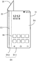
- FIGS. 5A to 8B are schematic diagrams of states of the electronic device 100 in a self-response adaptation mode according to an embodiment of the present application.
- FIG. 5A to FIG. 5B is a folding angle between the display surface of the first screen 31 and the display surface of the third screen 35 in an embodiment of the present application is 180. Degree of the state diagram. In this state, the display window D1 occupies the entire screen of the first screen 31. A window boundary line E1 of the display window D1 is exactly an edge line connecting the first screen 31 to the second screen 33. In addition, a date and time, a plurality of application icons, and the like are displayed on the display window D1.
- FIGS. 6A to 6B are folding angles between the display surface of the first screen 31 and the display surface of the third screen 35 in an embodiment of the present application that are greater than 90 degrees.
- State diagram Different from the state where the folding angle is 180, the display window D1 occupies the entire screen of the first screen 31 and a part of the screen of the second screen 33.
- the window boundary line E1 of the display window D1 is shifted leftward from the first screen 31 to a direction close to the second screen 33.
- the date and time located in the display window D1 moves to the left in a direction close to the second screen 33 as the area boundary surface E1 moves.
- the column spacing between the plurality of application icons located in the display window D1 increases as the window boundary line E1 moves to the left.
- FIGS. 7A to 7B are folding angles between the display surface of the first screen 31 and the display surface of the third screen 35 in the embodiment of the present application are less than 90 degrees State diagram. Unlike the state where the folding angle is greater than 90, the display window D1 occupies the entire screen of the first screen 31 and the second screen 33 and a part of the screen of the third screen 35. The window boundary line E1 of the display window D1 continues to move from the second screen 33 to the left to the third screen 35. The date and time located in the display window D1 continues to move to the left as the area boundary surface E1 moves to the left. The column spacing between the plurality of application icons located in the display window D1 continues to increase as the window boundary line E1 moves to the left.
- FIGS. 8A to 8B are a folding angle between the display surface of the first screen 31 and the display surface of the third screen 35 in an embodiment of the present application is 0 degrees.
- State diagram Unlike the state where the folding angle is less than 90, the display window D1 occupies the entire screen of the first screen 31, the second screen 33, and the third screen 35.
- the window boundary line E1 of the display window D1 is moved from the third screen 35 to the left of the third screen.
- the date and time located in the display window D1 moves to the upper left of the third screen 35 as the window boundary line E1 moves to the left.
- the column spacing between the plurality of application icons located in the display window D1 continues to increase as the window boundary line E1 moves to the left.
- the bendable electronic device 100 can automatically adapt the display content layout in the display window D1 and the display window D1 according to different bending angles to enhance the user experience.
- FIGS. 9A to 12B are schematic diagrams of states of the electronic device 100 in a non-self-response adaptation mode according to an embodiment of the present application.
- the processor 10 controls the flexible display screen 30 to display a graphical user interface G1 (as shown in FIG. 11B).
- the graphical user interface G1 includes a lower-layer wallpaper G11 and an upper-layer interface G12.
- the processor 10 controls the display window D1 to enter a non-self-responsive adaptation mode and the display window D1 is increased from small, the processor 10 controls the underlying wallpaper G11 to follow the change in the size of the display window D1 to perform a self-response Adapt, to control the content on the upper interface G12 to remain unchanged.
- the processor 10 controls the upper-layer interface G12 to adjust the display content layout thereon to fit the display window D1.
- the display window D1 includes a first screen display area D11 and a non-first screen display area D12.
- the first screen display area D11 refers to an area of the display window D1 corresponding to the first screen 31, and the non-first screen display area D12 refers to the display window D1 corresponding to the second screen 33 And / or an area of the third screen 35.
- the first screen display area D11 and the non-first screen display area D12 are separated by a hidden area boundary line B1.
- the processor 10 controls the display window D1 to perform non-self-responsive adaptation, the processor 10 controls the bottom wallpaper G11 located in the first screen display area D11 to be displayed with a first display attribute, and controls the display located at the non-first The bottom wallpaper G11 in the screen display area D12 is displayed with the second display attribute.
- the processor 10 controls the display attributes of the bottom wallpaper G11 in the non-first screen display area D12 to be determined by The second display attribute is gradually changed to the first display attribute.
- the processor 10 controls the size of the display window D1 to increase to the maximum value
- the processor 10 controls the bottom wallpaper G11 in the non-first screen display area D12 to be displayed with the first display attribute.
- the first display attribute includes high definition and high display brightness
- the second display attribute includes low definition and low display brightness. That is, in the process that the processor 10 controls the size of the display window D1 to increase from small, the processor 10 controls the underlying wallpaper G11 in the non-first screen display area D12 to be blurred accordingly. Clear, dark to light changes.
- FIG. 9A to FIG. 9B is a folding angle between the display surface of the first screen 31 and the display surface of the third screen 35 in an embodiment of the present application is 180 Degree of the state diagram.
- the display window D1 occupies the entire screen of the first screen 31.
- a window boundary line E1 of the display window D1 is exactly an edge line connecting the first screen 31 to the second screen 33.
- the display window D1 includes only the first screen display area D11.
- a date and time, a plurality of application icons, and the like are displayed on the display window D1.
- FIGS. 10A to 10B are folding angles between the display surface of the first screen 31 and the display surface of the third screen 35 in the embodiment of the present application are greater than 90 degrees.
- the window boundary line E1 of the display window D1 is shifted leftward from the first screen 31 to a direction close to the second screen 33.
- the display window D1 includes a first screen display area D11 and a non-first screen display area D12.
- the date and time and the column spacing between the multiple application icons located in the first screen display area D11 remain unchanged as the window boundary line E1 moves to the left.
- the processor 10 controls the bottom wallpaper G11 in the first screen display area D11 to be displayed with a first display attribute, and controls the display attributes of the bottom wallpaper G11 in the non-first screen display area D12 to follow the display.
- the left shift of the window boundary line E1 of the window D1 gradually changes from the second display attribute to the first display attribute.
- FIGS. 11A to 11B are folding angles between the display surface of the first screen 31 and the display surface of the third screen 35 in an embodiment of the present application that are smaller than 90 degrees.
- State diagram. Unlike the state where the folding angle is greater than 90, the display window D1 occupies the entire screen of the first screen 31 and the second screen 33 and a part of the screen of the third screen 35.
- the window boundary line E1 of the display window D1 continues to move from the second screen 33 to the left to the third screen 35.
- the display window D1 includes a first screen display area D11 and a non-first screen display area D12.
- the date and time and the column spacing between the plurality of application icons located in the first screen display area D11 remain unchanged as the window boundary line E1 is shifted to the left.
- the processor 10 controls the bottom wallpaper G11 in the first screen display area D11 to be displayed with a first display attribute.
- the processor 10 controls the display attributes of the bottom wallpaper G11 in the non-first screen display area D12 to further gradually change from the second display attributes to the selected display attributes as the window boundary line E1 of the display window D1 moves to the left
- the first display attribute is described.
- FIG. 12A to FIG. 12B is an embodiment in which the folding angle between the display surface of the first screen 31 and the display surface of the third screen 35 is 0 degrees.
- State diagram Unlike the state where the folding angle is less than 90, the display window D1 occupies the entire screen of the first screen 31, the second screen 33, and the third screen 35.
- the window boundary line E1 of the display window D1 is moved from the third screen 35 to the left of the third screen.
- the display window D1 includes a first screen display area D11 and a non-first screen display area D12.
- the date and time and the plurality of application icons located in the first screen display area D11 are readjusted and displayed on the entire screen of the display window D1.
- the processor 10 controls the bottom wallpaper G11 in the first screen display area D11 and the bottom wallpaper G11 in the non-first screen display area D12 to be displayed with a first display attribute.
- FIG. 13 is a flowchart of an interface adaptation method according to an embodiment of the present application.
- the interface adaptation method is applied to the aforementioned electronic device 100, and the execution order is not limited to the order shown in FIG.
- the method includes steps:
- step 1301 the flexible display screen 30 is controlled to display a display window D1, and the display window D1 covers at least the first screen 31.
- Step 1303 Obtain a bending angle between the display surface of the first screen 31 and the display surface of the second screen 33 sensed by the angle sensor 40.
- Step 1305 When the interface adaptation mode is a self-response adaptation mode, adjust the size of the display window D1 according to the bending angle sensed by the angle sensor 40 and the size of the display window D1. Adjusting the display content layout in the display window D1.
- adjusting the size of the display window D1 according to the bending angle sensed by the angle sensor 40 is specifically:
- the size of the display window D1 is adjusted according to the corresponding relationship and the bending angle sensed by the angle sensor 40.
- adjusting the size of the display window according to the bending angle sensed by the angle sensor 40 is specifically:
- the size of the display window D1 is adjusted to The display areas of the first screens 31 have the same size; or
- the size of the display window D1 is adjusted to The sum of the sizes of the display areas of the first screen 31 and the second screen 33 is the same; or
- the size of the window D1 is gradually adjusted from the display area equivalent to the first screen 31 to be consistent with the sum of the sizes of the display areas of the first screen 31 and the second screen 33.
- the flexible display screen 30 further includes a third screen 35, the at least one second screen 33 is connected between the third screen 35 and the first screen 31, and the angle sensor 40 senses A bending angle between the display surface of the first screen 31 and the display surface of the third screen 35 is detected, and “the display is adjusted according to the bending angle sensed by the angle sensor 40
- the size of window D1 is specifically:
- the size of the display window D1 is adjusted to The size of the display area of the first screen 31 is the same; or
- the size of the display window D1 is adjusted to The sum of the sizes of the display areas of the first screen 31, the second screen 33, and the third screen 35 is the same;
- the display is adjusted
- the size of the window D1 is gradually adjusted from the display area equivalent to the first screen 31 to be consistent with the sum of the sizes of the display areas of the first screen 31, the second screen 33, and the third screen 35.
- the interface adaptation method further includes steps:
- a currently applicable desktop adaptation mode is selected, wherein the desktop adaptation mode is a self-response adaptation mode and a non-self-response adaptation mode One of them.
- the interface adaptation method further includes steps:
- a corresponding desktop adaptation mode is determined Is a self-response adaptation mode
- the interface adaptation method further includes steps:
- the display window D1 When the display window D1 is controlled to enter the self-response adaptation mode, the display window D1 is controlled to perform self-response adaptation of the display content in the display window D1 according to a change in its size, and the self-response adaptation includes line spacing , Column spacing, word spacing, word size, icon spacing, icon size, picture size, layout change, navigation of the first level of content, navigation of the second level of content, and addition of related padding content.
- the flexible display screen 30 displays a graphical user interface G1.
- the graphical user interface G1 includes a bottom wallpaper G11 and an upper interface G12.
- the interface adaptation method further includes steps:
- the upper-layer interface G12 is controlled to adjust the layout of each interface element thereon.
- the display window D1 includes a first screen display area D11 and a non-first screen display area D12. There is a hidden region boundary between the first screen display area D11 and the non-first screen display area D12. Further, the interface adaptation method includes steps:
- control the underlying wallpaper G11 located in the first screen display area D11 to be displayed with a first display attribute, and control to be located in the non-first screen display area D12
- the underlying wallpaper G11 is displayed with a second display attribute.
- the interface adaptation method further includes steps:
- the present application further provides a computer-readable storage medium.
- the computer-readable storage medium stores a number of program instructions. After the plurality of program instructions are called and executed by the processor 10, FIG. 13 is executed. Any one of the method steps, so as to control the flexible display screen 30 to display a display window D1, and the display window D1 covers at least the first screen 31; and acquire the first sensed by the angle sensor 40 A bending angle between the screen 31 and the second screen 33; and when the desktop adaptation mode of the electronic device 100 is a self-response adaptation mode, according to the angle detected by the angle sensor 40 The bending angle adjusts the size of the display window D1 and adjusts the display content layout in the display window D1 according to the size of the display window D1.
- the computer storage medium is the memory 20, and may be any storage device that can store information, such as a memory card, a solid state memory, a micro hard disk, and an optical disc.
- the flexible display screen of the electronic device of the present application has a fully expanded state, a folded transition state, and a fully folded state, and the bending angles in each state are different.
- the processor adjusts the size of the display window according to the bending angle sensed by the angle sensor and adjusts the display content layout in the display window according to the size of the display window, which has better performance. user experience.
Landscapes
- Engineering & Computer Science (AREA)
- General Engineering & Computer Science (AREA)
- Theoretical Computer Science (AREA)
- Human Computer Interaction (AREA)
- Physics & Mathematics (AREA)
- General Physics & Mathematics (AREA)
- User Interface Of Digital Computer (AREA)
Abstract
本申请公开一种电子设备,包括处理器、柔性显示屏和角度感测器,处理器与柔性显示屏和角度感测器电性连接,柔性显示屏包括第一屏幕和至少一第二屏幕。角度感测器设置在第二屏幕上。处理器:控制柔性显示屏显示一显示窗口,显示窗口至少覆盖第一屏幕;获取角度感测器感测到的第一屏幕和第二屏幕之间的弯折角度;及在电子设备的桌面适配模式是自响应适配模式时,根据弯折角度调整显示窗口的大小及根据显示窗口的大小调整显示窗口内的显示内容布局。本申请还公开一种界面适配方法。本申请能够根据弯折角度调整显示窗口的大小及根据显示窗口的大小调整显示窗口内的显示内容布局,增强用户体验。
Description
本申请涉及一种图形用户界面控制领域,尤其涉及一种基于柔性显示屏的可弯折电子设备及其界面适配方法。
柔性显示屏作为液晶显示屏之后的新生代显示屏,其通过柔软的材料制成,可变形可弯曲,给用户带来新奇的使用体验。然而,现有的应用于不可弯折的电子设备的界面适配方法无法满足可弯折的电子设备。
发明内容
本申请实施例公开一种可弯折电子设备及其界面适配方法,以解决上述问题。
本申请实施例公开的可弯折电子设备,包括处理器、柔性显示屏和角度感测器,所述处理器与所述柔性显示屏和所述角度感测器电性连接,所述柔性显示屏包括第一屏幕和设置在所述第一屏幕一侧的第二屏幕,所述第二屏幕可绕弯曲轴相对所述第一屏幕弯曲。所述处理器控制所述柔性显示屏显示一显示窗口,所述显示窗口至少覆盖所述第一屏幕;获取所述角度感测器感测到的所述第一屏幕的显示面与所述第二屏幕的显示面之间的弯折角度;及在所述电子设备的桌面适配模式是自响应适配模式时,根据所述弯折角度调整所述显示窗口的大小及根据所述显示窗口的大小调整所述显示窗口内的显示内容的布局。
本申请实施例公开的一种界面适配方法,应用于一可弯折电子设备上,所述电子设备包括柔性显示屏和角度感测器,所述柔性显示屏包括第一屏幕和设置在所述第一屏幕一侧的第二屏幕,所述第二屏幕可绕弯曲轴相对所述第一屏幕弯曲。所述界面适配方法包括控制所述柔性显示屏显示一显示窗口,所述显示窗口至少覆盖所述第一屏幕;获取所述角度感测器感测到的所述第一屏幕和所述第二屏幕之间的弯折角度;及在所述电子设备的桌面适配模式是自响应适配模式时,根据所述弯折角度调整所述显示窗口的大小及根据所述显示窗口的大小调整所述显示窗口内的显示内容布局。
本申请实施例公开的一种计算机可读存储介质,所述计算机可读存储介质存储有计算机程序,所述计算机程序被处理器执行时实现所述界面适配方法的步骤。
本申请的电子设备的可弯折电子设备及其界面适配方法,能够在所述电子设备的桌面适配模式是自响应适配模式时,根据所述角度感测器感测到的所述弯折角度调整所述显示窗口的大小及根据所述显示窗口的大小调整所述显示窗口内的显示内容布局。从而,能够根据不同的弯折角度进行显示窗口及显示窗口内的显示内容布局的适配,增强用户体验。
为了更清楚地说明本申请实施例中的技术方案,下面将对实施例中所需要使用的附图作简单地介绍,显而易见地,下面描述中的附图仅仅是本申请的一些实施例,对于本领域普通技术人员来讲,在不付出创造性劳动的前提下,还可以根据这些附图获得其他的附图。
图1为本申请一实施例中的可弯折电子设备的模块示意框图。
图2为本申请第一实施例中的电子设备的结构示意图。
图3为本申请第二实施例中的电子设备的结构示意图。
图4为本申请第三实施例中的电子设备的结构示意图。
图5A至图8B为本申请一实施例中所述电子设备处于自响应适配模式的状态示意图。
图9A至图12B为本申请一实施例中所述电子设备处于非自响应适配模式的状态示意图。
图13为本申请一实施例中的应用于电子设备的界面适配方法的流程图。
下面将结合本申请实施例中的附图,对本申请实施例中的技术方案进行清楚、完整地描述,显然,所描述的实施例仅是本申请一部分实施例,而不是全部的实施例。基于本申请中的实施例,本领域普通技术人员在没有做出创造性劳动前提下所获得的所有其他实施例,都属于本申请保护的范围。
本发明的说明书和权利要求书及上述附图中的术语“包括”以及它们任何变形,意图在于覆盖不排他的包含。例如包含了一系列步骤或单元的过程、方法、系统、产品或设备没有限定于已列出的步骤或单元,而是可选地还包括没有列出的步骤或单元,或可选地还包括对于这些过程、方法、产品或设备固有的其它步骤或单元。本申请的说明书和权利要求书及上述附图中的术语“第一”、“第二”和“第三”等是用于区别不同对象,而非用于描述特定顺序。
请参阅图1,为本申请一实施例中的电子设备100的结构框图。所述电子设备100可以是但不限于手机、平板电脑、电子阅读器、穿戴式电子设备等,本申请实施例不做限定。所述电子设备100包括但不限于处理器10,以及分别与所述处理器10电性连接的存储器20、柔性显示屏30和角度感测器40。本领域技术人员应当理解的是,所述图1仅是所述电子设备100的示例,并不构成对所述电子设备100的限定,所述电子设备100可以包括比图1所示更多或更少的部件,或者组合某些部件,或者不同的部件,例如所述电子设备100还可以包括输入输出设备、网络接入设备、总线等。
所述处理器10可以是中央处理单元(Central Processing Unit,CPU),还可以是其他通用处理器、数字信号处理器(Digital Signal Processor,DSP)、专用集成电路(Application Specific Integrated Circuit,ASIC)、现成可编程门阵列(Field-Programmable Gate Array,FPGA)或者其他可编程逻辑器件、分立门或者晶体管逻辑器件、分立硬件组件等。所述通用处理器可以是微处理器或者所述处理器也可以是任何常规的处理器等。所述处理器是所述电子设备100的控制中心,利用各种接口和线路连接整个所述电子设备100的各个部分。
所述存储器20可用于存储所述计算机程序和/或模块,所述处理器10通过运行或执行存储在所述存储器20内的计算机程序和/或模块,以及调用存储在存储器20内的数据,实现所述电子设备100的各种功能。所述存储器20可主要包括存储程序区和存储数据区,其中,存储程序区可存储操作系统、多个功能所需的应用程序(比如声音播放功能、图像播放功能等)等;存储数据区可存储根据电子设备的使用所创建的数据(比如音频数据、电话本等)等。此外,所述存储器20可以包括高速随机存取存储器,还可以包括非易失性存储器,例如硬盘、内存、插接式 硬盘,智能存储卡(Smart Media Card,SMC),安全数字(Secure Digital,SD)卡,闪存卡(Flash Card)、多个磁盘存储器件、闪存器件、或其他易失性固态存储器件。
请参考图2,图2为本申请第一实施例中的电子设备100的结构示意图。所述柔性显示屏30包括第一屏幕31和第二屏幕33。所述第二屏幕33位于所述第一屏幕31的一侧。所述第二屏幕33可绕弯曲轴相对所述第一屏幕31弯曲。在一实施例中,所述第二屏幕33自所述第一屏幕31的一侧弯折延伸而形成,即所述第一屏幕31和所述第二屏幕33由一大屏幕沿一对应的弯折线弯折而成。
请参考图3,图3为本申请第二实施例中的电子设备100a的结构示意图。在该实施例中,所述第一屏幕31与所述第二屏幕33在一侧上相连,也就是说,所述第一屏幕31和所述第二屏幕33由两个单独的屏幕连接而成。
每个第二屏幕33上对应设置至少一个所述角度感测器40。所述角度感测器40感测所述第一屏幕31的显示面和所述第二屏幕33的显示面的弯折角度。
可理解,当所述第二屏幕33和所述第一屏幕31完全展开即所述第二屏幕33的显示面和所述第一屏幕31显示面位于同一水平面时,所述角度感测器40感测到的弯折角度为0度。当所述第二屏幕33弯折至所述第二屏幕33远离所述第一屏幕31的一端的显示面与所述第一屏幕31的显示面平行时,所述角度感测器40感测到的弯折角度为180度。当所述第二屏幕33相对所述第一屏幕31弯折时,所述角度感测器40感测到的弯折角度在0-180度之间变化。
请一并参考图5A和图5B,所述处理器10控制所述柔性显示屏30显示一显示窗口D1,所述显示窗口D1至少覆盖所述第一屏幕31。所述处理器10获取所述角度感测器40感测到的所述第一屏幕31的显示面和所述第二屏幕33的显示面之间的弯折角度。所述处理器10在所述角度感测器40感测到所述弯折角度变化且所述电子设备100的桌面适配模式是自响应适配模式时,根据所述角度感测器40感测到的弯折角度调整所述显示窗口D1的大小及根据所述显示窗口D1的大小调整所述显示窗口D1内的显示内容布局。
具体地,所述显示窗口D1是指所述柔性显示屏30上用于进行内容显示的区域。所述显示窗口D1可能覆盖所述柔性显示屏30的整个屏幕,也可以覆盖所述柔性显示屏30的部分屏幕,但至少覆盖所述第一屏幕31的整个屏幕。所述显示内容包括但不限于位于桌面上的应用图标、应用程序的界面内容等。所述应用图标可以是各种应用图标,例如通信应用图标,可以包括但不限于通话应用图标、短信应用图标和即时信息应用图标,所述即时信息应用图标可以包括但不限于:QQ应用图标、微信应用图标、微博应用图标等。所述应用程序的界面内容是指通过点击这些应用图标进入对应的应用程序之后显示的内容。
为了方便描述,将与所述第二屏幕33的轴线相平行的方向定义为宽度方向W,将与所述宽度方向W相垂直且所述第一屏幕31的显示面相平行的方向定义为长度方向L。本实施例中,无论所述显示窗口D1是否在长度方向L覆盖所述柔性显示屏30的整个屏幕,所述显示窗口D1在宽度方向W都完全覆盖所述柔性显示屏30的对应屏幕部分。当然,在其他实施例中,显示窗口D1也可以在宽度方向W部分覆盖柔性触控显示屏30。
本申请的可弯折电子设备100在其桌面适配模式是自响应适配模式时,能够根据所述角度感测器40感测到的 所述弯折角度调整所述显示窗口D1的大小及根据所述显示窗口D1的大小调整所述显示窗口D1内的显示内容布局。从而,所述电子设备100能够根据不同的弯折角度进行显示窗口D1及显示窗口D1内的显示内容布局的适配,增强用户体验。
进一步地,所述存储器20存储预设弯折角度与显示窗口D1大小的对应关系,所述处理器10根据所述对应关系和所述角度感测器40感测到的弯折角度来调整所述显示窗口D1的大小。可理解,所述对应关系可以是线性的、非线性的、阶梯的等,此处不做限制。
从而,每个弯折角度或者每个弯折角度区间可对应一个对应大小的显示窗口D1,使得所述显示窗口D1的大小能够根据弯折角度的变化得到动态调整,具有更好的用户体验。
具体地,在所述角度感测器40感测到所述第二屏幕33的显示面和所述第一屏幕31的显示面之间的弯折角度为180度,即所述柔性显示屏30处于完全弯折状态时,所述处理器10调整所述显示窗口D1的大小与所述第一屏幕31的显示区域大小一致。在所述角度感测器40感测到所述第二屏幕33的显示面和所述第一屏幕31的显示面之间的弯折角度为0度,即所述柔性显示屏30处于完全展开状态时,所述处理器10调整所述显示窗口D1的大小与所述第一屏幕31和所述第二屏幕33的显示区域的大小之和一致。具体地,在所述角度感测器40感测到所述第二屏幕33的显示面和所述第一屏幕31的显示面之间的弯折角度由180度趋近于0度,即所述柔性显示屏30处于展开过渡状态时,所述处理器10调整所述显示窗口D1的大小由等同于所述第一屏幕31的显示区域逐渐调整至与所述第一屏幕31和所述第二屏幕33的显示区域的大小之和相一致。
请参考图4,图4为本申请第三实施例中的电子设备100b的结构示意图。其中,所述柔性显示屏30包括第一屏幕31、第二屏幕33和第三屏幕35。所述第二屏幕33位于所述第一屏幕31和所述第三屏幕35之间,所述第二屏幕33与所述柔性显示屏30处于弯折状态下的弯折区域相对应,也就是说,所述第一屏幕31、第二屏幕33和第三屏幕35由一大屏幕沿着对应的弯折线弯折而成。
所述角度感测器40感测到所述第一屏幕31的显示面和所述第三屏幕35的显示面之间的弯折角度。其中,所述弯折角度是指所述第一屏幕31的显示面与所述第三屏幕35的显示面之间的弯折角度。在所述角度感测器40感测到所述第三屏幕35的显示面和所述第一屏幕31的显示面之间的弯折角度为180度时,所述处理器10调整所述显示窗口D1的大小与所述第一屏幕31的显示区域大小一致。在所述角度感测器40感测到所述第三屏幕35的显示面和所述第一屏幕31的显示面之间的弯折角度为0度时,所述处理器10调整所述显示窗口D1的大小与所述第一屏幕31、所述第二屏幕33和所述第三屏幕35的显示区域的大小之和一致。在所述角度感测器40感测到所述第三屏幕35的显示面和所述第一屏幕31的显示面之间的弯折角度由180度趋近于0度时,所述处理器10调整所述显示窗口D1的大小由等同于所述第一屏幕31的显示区域逐渐调整至与所述第一屏幕31、所述第二屏幕33和所述第三屏幕35的显示区域的大小之和相一致。
进一步地,所述处理器10在所述角度感测器40感测到所述弯折角度变化时,所述电子设备100还选择当前适用的桌面适配模式。其中,所述桌面适配模式是自响应适配模式和非自响应适配模式中的其中一种。所述自响应 适配模式是指可根据所述显示窗口D1的大小自动调整位于所述显示窗口D1内的显示内容的布局。所述非响应适配模式是指不能根据所述显示窗口D1的大小自动调整位于所述显示窗口D1内的显示内容的布局。
具体地,所述处理器10在所述电子设备100当前处于桌面状态时,确定对应的桌面适配模式为自响应适配模式。也就是说,所述电子设备100当前处于桌面状态时,所述处理器10便控制所述显示窗口D1进入自响应适配模式,控制所述显示窗口D1内的显示内容,例如多个应用程序图标,根据所述显示窗口D1的大小调节在所述显示窗口D1内的布局。
具体地,所述处理器10在所述电子设备100上当前正在前台运行且位于所述显示窗口D1内的所有应用程序的适配属性为自响应时,确定桌面适配模式为自响应适配模式。当所述处理器10在控制所述显示窗口D1进入自响应适配模式且所述显示窗口D1内显示多个显示内容,例如多个应用程序图标,时,控制所述显示窗口D1根据其大小的变化进行所述显示窗口D1内的多个应用程序的图标自响应适配,所述自响应适配包括图标间距、图标大小中的至少一种。所述“图标间距”是指所述显示窗口D1内排列显示的多个图标之间的间距。所述“图标大小”是指所述显示窗口D1内每个图标的大小。
当所述处理器10在控制所述显示窗口D1进入自响应适配模式且所述显示窗口D1内显示某一应用程序的显示界面时,控制该显示界面进行自响应适配,所述自响应适配包括行间距、列间距、字间距、字大小、图片大小、版式变化、导航第一层级的内容、导航第二层级的内容、新增相关填充内容适配中的至少一种。
所述“行间距”是指所述显示窗口D1内排列显示的多个显示内容之间的行间距。所述“列间距”是指所述显示窗口D1内排列显示的多个显示内容之间的列间距。所述“字间距”是指所述显示窗口D1内多个文字之间的字间距。所述“字大小”是指所述显示窗口D1内的文字大小。所述“图片大小”是指所述显示窗口D1内显示的每张图片的大小。所述“导航第一层级的内容”是指预存的被归为第一层级的内容。所述“导航第二层级的内容”是指预存的被归为第二层级的内容。比如,图片应用程序的若干图片被划分为若干层级,第一层级包括生活、旅行等,第二层级包括第一拍照地点、第二拍照地点等。所述“导航第二层级的内容”是指显示第一层级的内容,例如,生活、旅行等。所述“导航第二层级的内容”是指显示第二层级的内容,比如,具体显示“生活”的第二层级的具体图片,例如,第一拍照地点的生活图片,第二拍照地点的生活图片等。所述“新增相关填充内容”是指根据显示窗口D1的大小将新的显示内容按照预定次序添加在显示窗口D1内进行显示。所述“按照预定次序添加在显示窗口D1内进行显示”是指多个显示内容按照逐行或者逐列的填充方式依次添加。例如,在一实施例中,显示窗口D1内当前显示四行四列共16张图片时,该16张图片中,第一行的四张图片的次序为1、2、3、4,第二行的四张图片的次序为5、6、7、8,以此类推。当显示窗口D1增大到可以显示四行五列图片时,该16张图片先依次填满第一行、第二行、第三行,并在第四行从左至右依次增加新的显示内容进行显示。当然,上述填充方式仅是一种优选的方式,其他的填充方式,如在原来的每两个相邻的显示内容之间插入一个新的显示内容,或者将原来的显示内容后移,将新的显示内容前置等方式都可以适用于本实施例。
具体地,所述处理器10在所述电子设备10上当前正在前台运行且位于所述显示窗口D1内的至少一应用程 序的适配属性为非自响应时,确定桌面适配模式为非自响应适配模式。
请参考图5A至8B,图5A至图8B为本申请一实施例中所述电子设备100处于自响应适配模式的状态示意图。
具体地,请首先参考图5A至图5B,图5A至图5B为本申请一实施例中所述第一屏幕31的显示面和所述第三屏幕35的显示面之间的折叠角度为180度的状态示意图。在此状态下,所述显示窗口D1占据所述第一屏幕31的整个屏幕。所述显示窗口D1的窗口边界线E1正好是所述第一屏幕31连接所述第二屏幕33的边缘线。并且,所述显示窗口D1上显示日期时间及多个应用程序图标等。
具体地,请参考图6A至图6B,图6A至图6B为本申请一实施例中所述第一屏幕31的显示面和所述第三屏幕35的显示面之间的折叠角度大于90度的状态示意图。与折叠角度为180的状态不同的是,所述显示窗口D1占据所述第一屏幕31的整个屏幕和所述第二屏幕33的部分屏幕。所述显示窗口D1的窗口边界线E1从所述第一屏幕31向靠近所述第二屏幕33的方向左移。位于所述显示窗口D1内的日期时间随着所述区域边界面E1的移动向靠近所述第二屏幕33的方向左移。位于所述显示窗口D1内的多个应用程序图标之间的列间距随着所述窗口边界线E1的左移而增大。
具体地,请参考图7A至图7B,图7A至图7B为本申请一实施例中所述第一屏幕31的显示面和所述第三屏幕35的显示面之间的折叠角度小于90度的状态示意图。与折叠角度大于90的状态不同的是,所述显示窗口D1占据所述第一屏幕31和第二屏幕33的整个屏幕以及所述第三屏幕35的部分屏幕。所述显示窗口D1的窗口边界线E1从所述第二屏幕33内继续向左移动至所述第三屏幕35内。位于所述显示窗口D1内的日期时间随着所述区域边界面E1的左移而继续左移。位于所述显示窗口D1内的多个应用程序图标之间的列间距随着所述窗口边界线E1的左移而继续增大。
具体地,请参考图8A至图8B,图8A至图8B为本申请一实施例中所述第一屏幕31的显示面和所述第三屏幕35的显示面之间的折叠角度为0度的状态示意图。与折叠角度小于90的状态不同的是,所述显示窗口D1占据所述第一屏幕31、第二屏幕33以及所述第三屏幕35的整个屏幕。所述显示窗口D1的窗口边界线E1从所述第三屏幕35内左移至所述第三屏幕的边缘处。位于所述显示窗口D1内的日期时间随着所述窗口边界线E1的左移而移动至所述第三屏幕35的左上方。位于所述显示窗口D1内的多个应用程序图标之间的列间距随着所述窗口边界线E1的左移而继续增大。
从而,所述可弯折电子设备100能够根据不同的弯折角度进行显示窗口D1及显示窗口D1内的显示内容布局的自动适配,增强用户体验。
请参考图9A至12B,图9A至图12B为本申请一实施例中所述电子设备100处于非自响应适配模式的状态示意图。
所述处理器10控制所述柔性显示屏30显示一图形用户界面G1(如图11B所示)。所述图形用户界面G1包括底层壁纸G11和上层界面G12。所述处理器10在控制所述显示窗口D1进入非自响应适配模式且所述显示窗口D1由小增大时,控制所述底层壁纸G11跟随所述显示窗口D1的大小的变化进行自响应适配,控制所述上层界面 G12上的内容保持不变。所述处理器10在所述显示窗口D1的大小达到最大时,控制所述上层界面G12调整其上的显示内容布局以适配所述显示窗口D1。
进一步地,所述显示窗口D1包括第一屏幕显示区域D11和非第一屏幕显示区域D12。其中,所述第一屏幕显示区域D11是指所述显示窗口D1对应所述第一屏幕31的区域,所述非第一屏幕显示区域D12是指所述显示窗口D1对应所述第二屏幕33和/或所述第三屏幕35的区域。所述第一屏幕显示区域D11和所述非第一屏幕显示区域D12之间通过一条隐藏的区域分界线B1进行分界。所述处理器10在控制所述显示窗口D1进行非自响应式适配时,控制位于所述第一屏幕显示区域D11内的底层壁纸G11以第一显示属性显示,控制位于所述非第一屏幕显示区域D12内的底层壁纸G11以第二显示属性显示。
进一步地,所述处理器10在控制所述显示窗口D1的尺寸由小增大的过程中,所述处理器10控制所述非第一屏幕显示区域D12内的底层壁纸G11的显示属性由所述第二显示属性逐渐转变为所述第一显示属性。所述处理器10在控制所述显示窗口D1的尺寸增大到最大值时,所述处理器10控制所述非第一屏幕显示区域D12内的底层壁纸G11以所述第一显示属性显示。其中,所述第一显示属性包括高清晰度和高显示亮度,所述第二显示属性包括低清晰度和低显示亮度。也就是说,所述处理器10在控制所述显示窗口D1的尺寸由小增大的过程中,所述处理器10控制所述非第一屏幕显示区域D12内的底层壁纸G11相应发生模糊到清晰、暗到亮的变化。
具体地,请首先参考图9A至图9B,图9A至图9B为本申请一实施例中所述第一屏幕31的显示面和所述第三屏幕35的显示面之间的折叠角度为180度的状态示意图。在此状态下,所述显示窗口D1占据所述第一屏幕31的整个屏幕。所述显示窗口D1的窗口边界线E1正好是所述第一屏幕31连接所述第二屏幕33的边缘线。显然,所述显示窗口D1仅包括第一屏幕显示区域D11。并且,所述显示窗口D1上显示日期时间及多个应用程序图标等。
具体地,请参考图10A至图10B,图10A至图10B为本申请一实施例中所述第一屏幕31的显示面和所述第三屏幕35的显示面之间的折叠角度大于90度的状态示意图。与折叠角度为180的状态不同的是,所述显示窗口D1占据所述第一屏幕31的整个屏幕和所述第二屏幕33的部分屏幕。所述显示窗口D1的窗口边界线E1从所述第一屏幕31向靠近所述第二屏幕33的方向左移。所述显示窗口D1包括第一屏幕显示区域D11和非第一屏幕显示区域D12。位于所述第一屏幕显示区域D11内的日期时间和多个应用程序图标之间的列间距随着所述窗口边界线E1的左移而保持不变。所述处理器10控制所述第一屏幕显示区域D11内的底层壁纸G11以第一显示属性显示,并控制所述非第一屏幕显示区域D12内的底层壁纸G11的显示属性随着所述显示窗口D1的窗口边界线E1的左移由所述第二显示属性逐渐转变为所述第一显示属性。
具体地,请参考图11A至图11B,图11A至图11B为本申请一实施例中所述第一屏幕31的显示面和所述第三屏幕35的显示面之间的折叠角度小于90度的状态示意图。与折叠角度大于90的状态不同的是,所述显示窗口D1占据所述第一屏幕31和第二屏幕33的整个屏幕以及所述第三屏幕35的部分屏幕。所述显示窗口D1的窗口边界线E1从所述第二屏幕33内继续向左移动至所述第三屏幕35内。所述显示窗口D1包括第一屏幕显示区域D11和非第一屏幕显示区域D12。位于所述第一屏幕显示区域D11内的日期时间和多个应用程序图标之间的列间距随着 所述窗口边界线E1的左移而保持不变。所述处理器10控制所述第一屏幕显示区域D11内的底层壁纸G11以第一显示属性显示。所述处理器10控制所述非第一屏幕显示区域D12内的底层壁纸G11的显示属性随着所述显示窗口D1的窗口边界线E1的左移由所述第二显示属性进一步逐渐转变为所述第一显示属性。
具体地,请参考图12A至图12B,图12A至图12B为本申请一实施例中所述第一屏幕31的显示面和所述第三屏幕35的显示面之间的折叠角度为0度的状态示意图。与折叠角度小于90的状态不同的是,所述显示窗口D1占据所述第一屏幕31、第二屏幕33以及所述第三屏幕35的整个屏幕。所述显示窗口D1的窗口边界线E1从所述第三屏幕35内左移至所述第三屏幕的边缘处。所述显示窗口D1包括第一屏幕显示区域D11和非第一屏幕显示区域D12。位于所述第一屏幕显示区域D11内的日期时间和多个应用程序图标重新调整布局并显示在所述显示窗口D1的整个屏幕上。所述处理器10控制所述第一屏幕显示区域D11内的底层壁纸G11和所述非第一屏幕显示区域D12内的底层壁纸G11均以第一显示属性显示。
请参阅图13,为本申请一实施例中的界面适配方法的流程图。所述界面适配方法应用于前述的电子设备100中,执行顺序并不限于图13所示的顺序。所述方法包括步骤:
步骤1301,控制所述柔性显示屏30显示一显示窗口D1,所述显示窗口D1至少覆盖所述第一屏幕31。
步骤1303,获取所述角度感测器40感测到的所述第一屏幕31的显示面和所述第二屏幕33的显示面之间的弯折角度。
步骤1305,当界面适配模式是自响应适配模式时,根据所述角度感测器40感测到的所述弯折角度调整所述显示窗口D1的大小及根据所述显示窗口D1的大小调整所述显示窗口D1内的显示内容布局。
具体地,“根据所述角度感测器40感测到的所述弯折角度调整所述显示窗口D1的大小”具体为:
调用预存的预设弯折角度与显示窗口D1大小的对应关系;及
根据所述对应关系和所述角度感测器40感测到的弯折角度来调整所述显示窗口D1的大小。
具体地,“根据所述角度感测器40感测到的所述弯折角度调整所述显示窗口的大小”具体为:
在所述角度感测器40感测到所述第二屏幕33的显示面和所述第一屏幕31的显示面之间的弯折角度为180度时,调整所述显示窗口D1的大小与所述第一屏幕31的显示区域大小一致;或
在所述角度感测器40感测到所述第二屏幕33的显示面和所述第一屏幕31的显示面之间的弯折角度为0度时,调整所述显示窗口D1的大小与所述第一屏幕31和所述第二屏幕33的显示区域的大小之和一致;或
在所述角度感测器40感测到所述第二屏幕33的显示面和所述第一屏幕31的显示面之间的弯折角度由180度趋近于0度时,调整所述显示窗口D1的大小由等同于所述第一屏幕31的显示区域逐渐调整至与所述第一屏幕31和所述第二屏幕33的显示区域的大小之和相一致。
进一步地,所述柔性显示屏30还包括第三屏幕35,所述至少一个第二屏幕33连接在所述第三屏幕35与所述第一屏幕31之间,所述角度感测器40感测到所述第一屏幕31的显示面和所述第三屏幕35的显示面之间的弯折角度,“根据所述角度感测器40感测到的所述弯折角度调整所述显示窗口D1的大小”具体为:
在所述角度感测器40感测到所述第三屏幕35的显示面和所述第一屏幕31的显示面之间的弯折角度为180度时,调整所述显示窗口D1的大小与所述第一屏幕31的显示区域的大小一致;或
在所述角度感测器40感测到所述第三屏幕35的显示面和所述第一屏幕31的显示面之间的弯折角度为0度时,调整所述显示窗口D1的大小与所述第一屏幕31、所述第二屏幕33和所述第三屏幕35的显示区域的大小之和一致;及
在所述角度感测器40感测到所述第三屏幕35的显示面和所述第一屏幕31的显示面之间的弯折角度由180度趋近于0度时,调整所述显示窗口D1的大小由等同于所述第一屏幕31的显示区域逐渐调整至与所述第一屏幕31、所述第二屏幕33和所述第三屏幕35的显示区域的大小之和相一致。
进一步地,所述界面适配方法还包括步骤:
在判定所述角度感测器40感测到所述弯折角度变化时,选择当前适用的桌面适配模式,其中,所述桌面适配模式是自响应适配模式和非自响应适配模式中的其中一种。
进一步地,所述界面适配方法还包括步骤:
在确定所述电子设备100当前处于桌面状态或所述电子设备100上当前正在前台运行且位于所述显示窗口D1内的所有应用程序的适配属性为自响应时,确定对应的桌面适配模式为自响应适配模式;及
在所述电子设备10上当前正在前台运行且位于所述显示窗口D1内的至少一应用程序的适配属性为非自响应时,确定对应的桌面适配模式为非自响应适配模式。
进一步地,所述界面适配方法还包括步骤:
在控制所述显示窗口D1进入自响应适配模式时,控制所述显示窗口D1根据其大小的变化进行所述显示窗口D1内的显示内容自响应适配,所述自响应适配包括行间距、列间距、字间距、字大小、图标间距、图标大小、图片大小、版式变化、导航第一层级的内容、导航第二层级的内容、新增相关填充内容中的至少一种。
所述柔性显示屏30显示一图形用户界面G1,所述图形用户界面G1包括底层壁纸G11和上层界面G12,所述界面适配方法还包括步骤:
控制所述显示窗口D1进入非自响应适配模式,且当所述显示窗口D1的大小变化时,控制所述底层壁纸G11跟随所述显示窗口D1的大小的变化进行自响应适配,控制所述上层界面G12上的内容保持不变;
当所述显示窗口D1的大小与所述柔性显示屏30的整个显示区域的大小一致时,控制所述上层界面G12调整其上的每个界面元素的布局。
所述显示窗口D1包括第一屏幕显示区域D11和非第一屏幕显示区域D12。所述第一屏幕显示区域D11和所述非第一屏幕显示区域D12之间具有一条隐藏的区域分界线。进一步地,所述界面适配方法包括步骤:
在控制所述显示窗口D1进行非自响应式适配时,控制位于所述第一屏幕显示区域D11内的底层壁纸G11以第一显示属性显示,控制位于所述非第一屏幕显示区域D12内的底层壁纸G11以第二显示属性显示。
进一步地,所述界面适配方法还包括步骤:
所述显示窗口D1的尺寸由小增大时,控制所述非第一屏幕显示区域D12内的底层壁纸G11的显示属性由所述第二显示属性逐渐转变为所述第一显示属性;当所述显示窗口D1的大小与所述柔性显示屏30的整个显示区域的大小一致时,控制所述非第一屏幕显示区域D12内的底层壁纸G11以所述第一显示属性显示,其中,所述第一显示属性包括高清晰度和高显示亮度,所述第二显示属性包括低清晰度和低显示亮度。所述逐渐转变为随着显示窗口D1的逐渐增大所述第二显示属性与所述第一显示属性之间的差距越来越小。
在一些实施例中,本申请还提供一种计算机可读存储介质,所述计算机可读存储介质中存储有若干程序指令,所述若干程序指令供所述处理器10调用执行后,执行图13的任一方法步骤,从而控制所述柔性显示屏30显示一显示窗口D1,所述显示窗口D1至少覆盖所述第一屏幕31;获取所述角度感测器40感测到的所述第一屏幕31和所述第二屏幕33之间的弯折角度;及在所述电子设备100的桌面适配模式是自响应适配模式时,根据所述角度感测器40感测到的所述弯折角度调整所述显示窗口D1的大小及根据所述显示窗口D1的大小调整所述显示窗口D1内的显示内容布局。在一些实施例中,所述计算机存储介质即为所述存储器20,可为存储卡、固态存储器、微硬盘、光盘等任意可存储信息的存储设备。
本申请的电子设备的柔性显示屏具有完全展开状态、折叠过渡状态和完全折叠状态,各个状态下的弯折角度不同。所述处理器根据所述角度感测器感测到的所述弯折角度调整所述显示窗口的大小及根据所述显示窗口的大小调整所述显示窗口内的显示内容布局,具有更好的用户体验。
需要说明的是,对于前述的各个方法实施例,为了简单描述,故将其都表述为一系列的动作组合,但是本领域技术人员应该知悉,本申请并不受所描述的动作顺序的限制,因为依据本申请,某一些步骤可以采用其他顺序或者同时进行。其次,本领域技术人员也应该知悉,说明书中所描述的实施例均属于优选实施例,所涉及的动作和模块并不一定是本申请所必须的。在上述实施例中,对各个实施例的描述都各有侧重,某个实施例中没有详细描述的部分,可以参见其他实施例的相关描述。本申请实施例方法中的步骤可以根据实际需要进行顺序调整、合并和删减。以上对本申请实施例进行了详细介绍,本文中应用了具体个例对本申请的原理及实施例进行了阐述,以上实施例的说明只是用于帮助理解本申请的方法及其核心思想;同时,对于本领域的一般技术人员,依据本申请的思想,在具体实施例及应用范围上均会有改变之处,综上所述,本说明书内容不应理解为对本申请的限制。
Claims (20)
- 一种可弯折电子设备,包括处理器、柔性显示屏和角度感测器,所述处理器与所述柔性显示屏和所述角度感测器电性连接,所述柔性显示屏包括第一屏幕和设置在所述第一屏幕一侧的第二屏幕,所述第二屏幕可绕弯曲轴相对所述第一屏幕弯曲,其特征在于,所述处理器:控制所述柔性显示屏显示一显示窗口,所述显示窗口至少覆盖所述第一屏幕;获取所述角度感测器感测到的所述第一屏幕的显示面与所述第二屏幕的显示面之间的弯折角度;及在所述电子设备的桌面适配模式是自响应适配模式时,根据所述弯折角度调整所述显示窗口的大小及根据所述显示窗口的大小调整所述显示窗口内的显示内容的布局。
- 如权利要求1所述的电子设备,其特征在于,所述电子设备还包括存储器,所述存储器与所述处理器电性连接,所述存储器存储预设弯折角度与显示窗口大小的对应关系,所述处理器根据所述对应关系和所述角度感测器感测到的弯折角度来调整所述显示窗口的大小。
- 如权利要求2所述的电子设备,其特征在于,所述处理器:在所述角度感测器感测到所述第二屏幕的显示面和所述第一屏幕的显示面之间的弯折角度为180度时,调整所述显示窗口的大小与所述第一屏幕的显示区域大小一致;或在所述角度感测器感测到所述第二屏幕的显示面和所述第一屏幕的显示面之间的弯折角度为0度时,调整所述显示窗口的大小与所述第一屏幕和所述第二屏幕的显示区域的大小之和一致;或在所述角度感测器感测到所述第二屏幕的显示面和所述第一屏幕的显示面之间的弯折角度由180度趋近于0度时,调整所述显示窗口的大小由等同于所述第一屏幕的显示区域逐渐调整至与所述第一屏幕和所述第二屏幕的显示区域的大小之和相一致。
- 如权利要求2所述的电子设备,其特征在于,所述柔性显示屏还包括第三屏幕,所述至少一个第二屏幕连接在所述第三屏幕与所述第一屏幕之间,所述角度感测器感测所述第一屏幕和所述第三屏幕之间的弯折角度,所述处理器:在所述角度感测器感测到所述第三屏幕的显示面和所述第一屏幕的显示面之间的弯折角度为180度时,调整所述显示窗口的大小与所述第一屏幕的显示区域大小一致;或在所述角度感测器感测到所述第三屏幕的显示面和所述第一屏幕的显示面之间的弯折角度为0度时,调整所述显示窗口的大小与所述第一屏幕、所述第二屏幕和所述第三屏幕的显示区域的大小之和一致;或在所述角度感测器感测到所述第三屏幕的显示面和所述第一屏幕的显示面之间的弯折角度由180度趋近于0度时,调整所述显示窗口的大小由等同于所述第一屏幕的显示区域逐渐调整至与所述第一屏幕、所述第二屏幕和所述第三屏幕的显示区域的大小之和相一致。
- 如权利要求3至4任一项所述的电子设备,其特征在于,所述处理器在判断出所述角度感测器感测到所述弯折角度变化时,选择当前适用的桌面适配模式,其中,所述桌面适配模式是自响应适配模式和非自响应适配模式 中的其中一种。
- 如权利要求5所述的电子设备,其特征在于,所述处理器在确定所述电子设备当前处于桌面状态或所述电子设备上当前正在前台运行且位于所述显示窗口内的所有应用程序的适配属性为自响应时,确定对应的桌面适配模式为自响应适配模式;所述处理器在确定所述电子设备上当前正在前台运行且位于所述显示窗口内的至少一应用程序的适配属性为非自响应时,确定对应的桌面适配模式为非自响应适配模式。
- 如权利要求6所述的电子设备,其特征在于,所述处理器在控制所述显示窗口进入自响应适配模式时,控制所述显示窗口内的显示内容根据所述显示窗口的大小的变化进行自响应适配,所述自响应适配包括行间距、列间距、字间距、字大小、图标间距、图标大小、图片大小、版式变化、导航第一层级的内容、导航第二层级的调整或者新增相关填充内容中的至少一种。
- 如权利要求6所述的电子设备,其特征在于,所述处理器控制所述柔性显示屏显示一图形用户界面,所述图形用户界面包括底层壁纸和上层界面,所述处理器在控制所述显示窗口进入非自响应适配模式,且所述显示窗口的大小由小增大时,控制所述底层壁纸跟随所述显示窗口的大小的变化进行自响应适配,控制所述上层界面上的内容保持不变,当所述显示窗口的大小与所述柔性显示屏的整个显示区域的大小一致时,控制所述上层界面调整其上的内容布局。
- 如权利要求8所述的电子设备,其特征在于,所述显示窗口包括第一屏幕显示区域和非第一屏幕显示区域,所述第一屏幕显示区域和所述非第一屏幕显示区域之间具有一条隐藏的区域分界线,所述处理器在控制所述显示窗口进入非自响应式适配模式时,控制位于所述第一屏幕显示区域内的底层壁纸以第一显示属性显示,控制位于所述非第一屏幕显示区域内的底层壁纸以第二显示属性显示。
- 如权利要求9所述的电子设备,其特征在于,所述显示窗口由小增大时,所述处理器控制所述非第一屏幕显示区域内的底层壁纸的显示属性由所述第二显示属性逐渐转变为所述第一显示属性,当所述显示窗口的大小与所述柔性显示屏的整个显示区域的大小一致时,所述处理器控制所述非第一屏幕显示区域内的底层壁纸以所述第一显示属性显示,其中,所述第一显示属性包括高清晰度和高显示亮度,所述第二显示属性包括低清晰度和低显示亮度。
- 一种界面适配方法,应用于一可弯折电子设备上,所述电子设备包括柔性显示屏和角度感测器,所述柔性显示屏包括第一屏幕和设置在所述第一屏幕一侧的第二屏幕,所述第二屏幕可绕弯曲轴相对所述第一屏幕弯曲;其特征在于,所述界面适配方法包括:控制所述柔性显示屏显示一显示窗口,所述显示窗口至少覆盖所述第一屏幕;获取所述角度感测器感测到的所述第一屏幕和所述第二屏幕之间的弯折角度;及在所述电子设备的桌面适配模式是自响应适配模式时,根据所述弯折角度调整所述显示窗口的大小及根据所述显示窗口的大小调整所述显示窗口内的显示内容布局。
- 如权利要求11所述的界面适配方法,其特征在于,所述界面适配方法包括:调用预存的预设弯折角度与显示窗口大小的对应关系;及根据所述对应关系和所述角度感测器感测到的弯折角度来调整所述显示窗口的大小。
- 如权利要求12所述的界面适配方法,其特征在于,所述界面适配方法包括:在所述角度感测器感测到所述第二屏幕的显示面和所述第一屏幕的显示面之间的弯折角度为180度时,调整所述显示窗口的大小与所述第一屏幕的显示区域大小一致;或在所述角度感测器感测到所述第二屏幕的显示面和所述第一屏幕的显示面之间的弯折角度为0度时,调整所述显示窗口的大小与所述第一屏幕和所述第二屏幕的显示区域的大小之和一致;或在所述角度感测器感测到所述第二屏幕的显示面和所述第一屏幕的显示面之间的弯折角度由180度趋近于0度时,调整所述显示窗口的大小由等同于所述第一屏幕的显示区域逐渐调整至与所述第一屏幕和所述第二屏幕的显示区域的大小之和相一致。
- 如权利要求12所述的界面适配方法,其特征在于,所述柔性显示屏还包括第三屏幕,所述至少一个第二屏幕连接在所述第三屏幕与所述第一屏幕之间,所述角度感测器感测所述第一屏幕和所述第三屏幕之间的弯折角度,所述界面适配方法包括:在所述角度感测器感测到所述第三屏幕的显示面和所述第一屏幕的显示面之间的弯折角度为180度时,调整所述显示窗口的大小与所述第一屏幕的显示区域大小一致;或在所述角度感测器感测到所述第三屏幕的显示面和所述第一屏幕的显示面之间的弯折角度为0度时,调整所述显示窗口的大小与所述第一屏幕、所述第二屏幕和所述第三屏幕的显示区域的大小之和一致;及在所述角度感测器感测到所述第三屏幕的显示面和所述第一屏幕的显示面之间的弯折角度由180度趋近于0度时,调整所述显示窗口的大小由等同于所述第一屏幕的显示区域逐渐调整至与所述第一屏幕、所述第二屏幕和所述第三屏幕的显示区域的大小之和相一致。
- 如权利要求13至14任一项所述的界面适配方法,其特征在于,所述界面适配方法还包括:在判断出所述角度感测器感测到所述弯折角度变化时,选择当前适用的桌面适配模式,其中,所述桌面适配模式是自响应适配模式和非自响应适配模式中的其中一种。
- 如权利要求15所述的界面适配方法,其特征在于,所述界面适配方法还包括:在确定所述电子设备当前处于桌面状态或所述电子设备上当前正在前台运行且位于所述显示窗口内的所有应用程序的适配属性为自响应时,确定对应的桌面适配模式为自响应适配模式;及在确定确定所述电子设备上当前正在前台运行且位于所述显示窗口内的至少一应用程序的适配属性为非自响应时,确定对应的桌面适配模式为非自响应适配模式。
- 如权利要求16所述的界面适配方法,其特征在于,所述界面适配方法还包括:在控制所述显示窗口进入自响应适配模式时,控制所述显示窗口内的显示内容根据所述显示窗口的大小的变化自响应适配,所述自响应适配包括行间距、列间距、字间距、字大小、图标间距、图标大小、图片大小、版式变化、导航第一层级的内容、导航第二层级的调整或者新增相关填充内容中的至少一种。
- 如权利要求16所述的界面适配方法,其特征在于,所述柔性显示屏显示一图形用户界面,所述图形用户界面包括底层壁纸和上层界面,所述界面适配方法还包括:控制所述显示窗口进入非自响应适配模式,且当所述显示窗口的大小由小增大时,控制所述底层壁纸跟随所述显示窗口的大小的变化进行自响应适配,控制所述上层界面上的内容保持不变;当所述显示窗口的大小与所述柔性显示屏的整个显示区域的大小一致时,控制所述上层界面调整其上的内容布局。
- 如权利要求18所述的界面适配方法,其特征在于,所述显示窗口包括第一屏幕显示区域和非第一屏幕显示区域,所述第一屏幕显示区域和所述非第一屏幕显示区域之间具有一条隐藏的区域分界线,所述界面适配方法包括:在控制所述显示窗口进入非自响应式适配模式时,控制位于所述第一屏幕显示区域内的底层壁纸以第一显示属性显示,控制位于所述非第一屏幕显示区域内的底层壁纸以第二显示属性显示。
- 如权利要求19所述的界面适配方法,其特征在于,所述界面适配方法包括:所述显示窗口的大小由小增大时,控制所述非第一屏幕显示区域内的底层壁纸的显示属性由所述第二显示属性逐渐转变为所述第一显示属性;当所述显示窗口的大小与所述柔性显示屏的整个显示区域的大小一致时,控制所述非第一屏幕显示区域内的底层壁纸以所述第一显示属性显示,其中,所述第一显示属性包括高清晰度和高显示亮度,所述第二显示属性包括低清晰度和低显示亮度。
Priority Applications (3)
| Application Number | Priority Date | Filing Date | Title |
|---|---|---|---|
| PCT/CN2018/107432 WO2020061783A1 (zh) | 2018-09-25 | 2018-09-25 | 可弯折电子设备及其界面适配方法 |
| CN202110728616.0A CN113467689A (zh) | 2018-09-25 | 2018-09-25 | 可弯折电子设备及其界面适配方法 |
| CN201880076483.XA CN111465917A (zh) | 2018-09-25 | 2018-09-25 | 可弯折电子设备及其界面适配方法 |
Applications Claiming Priority (1)
| Application Number | Priority Date | Filing Date | Title |
|---|---|---|---|
| PCT/CN2018/107432 WO2020061783A1 (zh) | 2018-09-25 | 2018-09-25 | 可弯折电子设备及其界面适配方法 |
Publications (1)
| Publication Number | Publication Date |
|---|---|
| WO2020061783A1 true WO2020061783A1 (zh) | 2020-04-02 |
Family
ID=69952601
Family Applications (1)
| Application Number | Title | Priority Date | Filing Date |
|---|---|---|---|
| PCT/CN2018/107432 Ceased WO2020061783A1 (zh) | 2018-09-25 | 2018-09-25 | 可弯折电子设备及其界面适配方法 |
Country Status (2)
| Country | Link |
|---|---|
| CN (2) | CN111465917A (zh) |
| WO (1) | WO2020061783A1 (zh) |
Cited By (4)
| Publication number | Priority date | Publication date | Assignee | Title |
|---|---|---|---|---|
| CN113687691A (zh) * | 2021-08-30 | 2021-11-23 | 维沃移动通信有限公司 | 显示方法、装置及电子设备 |
| CN116915897A (zh) * | 2023-09-05 | 2023-10-20 | 荣耀终端有限公司 | 显示方法、存储介质及电子设备 |
| US12340455B2 (en) | 2020-11-16 | 2025-06-24 | Guangdong Oppo Mobile Telecommunications Corp., Ltd. | Display control method, non-transitory computer-readable storage medium, and electronic device |
| EP4495757A4 (en) * | 2022-04-28 | 2025-07-23 | Huawei Tech Co Ltd | METHOD FOR DISPLAYING FLEXIBLE SCREEN ELECTRONIC DEVICE, AND ELECTRONIC DEVICE |
Families Citing this family (2)
| Publication number | Priority date | Publication date | Assignee | Title |
|---|---|---|---|---|
| CN114115769B (zh) * | 2020-08-31 | 2023-09-29 | 华为技术有限公司 | 一种显示方法及电子设备 |
| CN116302259A (zh) * | 2023-02-23 | 2023-06-23 | 深圳传音控股股份有限公司 | 显示方法、智能终端及存储介质 |
Citations (3)
| Publication number | Priority date | Publication date | Assignee | Title |
|---|---|---|---|---|
| US20130093669A1 (en) * | 2011-10-13 | 2013-04-18 | Samsung Electronics Co., Ltd. | Apparatus and method for controlling screen in wireless terminal |
| CN104754084A (zh) * | 2015-02-02 | 2015-07-01 | 联想(北京)有限公司 | 一种显示方法及电子设备 |
| CN108475171A (zh) * | 2015-12-28 | 2018-08-31 | 三星电子株式会社 | 具有柔性显示器的电子设备以及用于操作电子设备的方法 |
Family Cites Families (10)
| Publication number | Priority date | Publication date | Assignee | Title |
|---|---|---|---|---|
| CN101369210B (zh) * | 2008-08-22 | 2011-03-16 | 华为终端有限公司 | 一种调整用户界面元素的方法及装置 |
| CN103870040B (zh) * | 2012-12-13 | 2017-02-08 | 联想(北京)有限公司 | 一种信息处理的方法及电子设备 |
| CN104460949B (zh) * | 2013-09-13 | 2019-06-25 | 联想(北京)有限公司 | 一种数据处理方法及设备 |
| KR20150135038A (ko) * | 2014-05-23 | 2015-12-02 | 삼성전자주식회사 | 폴더블 전자 장치 및 그 제어 방법 |
| WO2016017948A1 (en) * | 2014-07-31 | 2016-02-04 | Samsung Electronics Co., Ltd. | Flexible device and interfacing method thereof |
| KR101515620B1 (ko) * | 2014-12-29 | 2015-05-04 | 삼성전자주식회사 | 사용자 단말 장치 및 그의 제어 방법 |
| KR102406091B1 (ko) * | 2015-04-01 | 2022-06-10 | 삼성전자주식회사 | 전자 장치 |
| CN107209557B (zh) * | 2015-12-25 | 2020-10-27 | 深圳市柔宇科技有限公司 | 柔性显示屏系统 |
| CN108089798A (zh) * | 2017-11-30 | 2018-05-29 | 努比亚技术有限公司 | 终端显示控制方法、柔性屏终端及计算机可读存储介质 |
| CN108196807B (zh) * | 2018-01-19 | 2021-08-13 | 云谷(固安)科技有限公司 | 可折叠显示屏的显示调整方法及显示装置 |
-
2018
- 2018-09-25 WO PCT/CN2018/107432 patent/WO2020061783A1/zh not_active Ceased
- 2018-09-25 CN CN201880076483.XA patent/CN111465917A/zh active Pending
- 2018-09-25 CN CN202110728616.0A patent/CN113467689A/zh active Pending
Patent Citations (3)
| Publication number | Priority date | Publication date | Assignee | Title |
|---|---|---|---|---|
| US20130093669A1 (en) * | 2011-10-13 | 2013-04-18 | Samsung Electronics Co., Ltd. | Apparatus and method for controlling screen in wireless terminal |
| CN104754084A (zh) * | 2015-02-02 | 2015-07-01 | 联想(北京)有限公司 | 一种显示方法及电子设备 |
| CN108475171A (zh) * | 2015-12-28 | 2018-08-31 | 三星电子株式会社 | 具有柔性显示器的电子设备以及用于操作电子设备的方法 |
Cited By (5)
| Publication number | Priority date | Publication date | Assignee | Title |
|---|---|---|---|---|
| US12340455B2 (en) | 2020-11-16 | 2025-06-24 | Guangdong Oppo Mobile Telecommunications Corp., Ltd. | Display control method, non-transitory computer-readable storage medium, and electronic device |
| CN113687691A (zh) * | 2021-08-30 | 2021-11-23 | 维沃移动通信有限公司 | 显示方法、装置及电子设备 |
| EP4495757A4 (en) * | 2022-04-28 | 2025-07-23 | Huawei Tech Co Ltd | METHOD FOR DISPLAYING FLEXIBLE SCREEN ELECTRONIC DEVICE, AND ELECTRONIC DEVICE |
| CN116915897A (zh) * | 2023-09-05 | 2023-10-20 | 荣耀终端有限公司 | 显示方法、存储介质及电子设备 |
| CN116915897B (zh) * | 2023-09-05 | 2024-03-08 | 荣耀终端有限公司 | 显示方法、存储介质及电子设备 |
Also Published As
| Publication number | Publication date |
|---|---|
| CN111465917A (zh) | 2020-07-28 |
| CN113467689A (zh) | 2021-10-01 |
Similar Documents
| Publication | Publication Date | Title |
|---|---|---|
| WO2020061783A1 (zh) | 可弯折电子设备及其界面适配方法 | |
| CN108491127B (zh) | 输入法界面显示方法、装置、终端及存储介质 | |
| CN108089786B (zh) | 用户界面显示方法、装置、设备及存储介质 | |
| US10331394B1 (en) | Manipulating shared screen content | |
| CN111866423B (zh) | 用于电子终端的录屏方法及相应设备 | |
| CN106919301B (zh) | 壁纸预览方法和系统以及壁纸更换方法和系统 | |
| CN108064371A (zh) | 一种柔性显示屏的控制方法及装置 | |
| US11640283B2 (en) | Control bar for element activation | |
| CN106126041B (zh) | 一种移动终端的桌面图标管理方法及移动终端 | |
| CN107943443A (zh) | 照片的显示控制方法、装置、存储介质及电子设备 | |
| CN107748656A (zh) | 一种画面显示方法、装置、终端及存储介质 | |
| WO2020029209A1 (zh) | 可弯折的移动终端及其信息通知方法 | |
| CN106201176A (zh) | 一种图像显示方法及移动终端 | |
| WO2021120756A1 (zh) | 显示方法、装置和计算机可读存储介质 | |
| US10388048B2 (en) | Simplified mechanism for displaying multiple documents on a mobile device | |
| WO2020206655A1 (zh) | 交互方法、柔性电子装置及可读存储介质 | |
| CN102622155A (zh) | 具有触控显示界面的电子装置及依时间区间显示影像图示的方法 | |
| CN112860157B (zh) | 显示元素调整方法、装置、设备及存储介质 | |
| CN111448534B (zh) | 终端设备及其图形用户界面以及图形用户界面的控制方法 | |
| US9658734B2 (en) | Information processing method and electronic device | |
| WO2018000832A1 (zh) | 一种终端屏幕内容的显示方法、显示装置以及终端 | |
| WO2016078528A1 (zh) | 展现对象信息的方法和装置 | |
| CN112689822A (zh) | 镜像显示方法、柔性显示装置及计算机可读存储介质 | |
| WO2024000111A1 (zh) | 桌面展示方法、电子设备、显示装置及计算机可读存储介质 | |
| CN116820280A (zh) | 界面遮挡控制方法、装置、计算机设备、存储介质 |
Legal Events
| Date | Code | Title | Description |
|---|---|---|---|
| 121 | Ep: the epo has been informed by wipo that ep was designated in this application |
Ref document number: 18935963 Country of ref document: EP Kind code of ref document: A1 |
|
| NENP | Non-entry into the national phase |
Ref country code: DE |
|
| 122 | Ep: pct application non-entry in european phase |
Ref document number: 18935963 Country of ref document: EP Kind code of ref document: A1 |