WO2020059564A1 - 情報処理方法、プログラム、および情報処理システム - Google Patents
情報処理方法、プログラム、および情報処理システム Download PDFInfo
- Publication number
- WO2020059564A1 WO2020059564A1 PCT/JP2019/035395 JP2019035395W WO2020059564A1 WO 2020059564 A1 WO2020059564 A1 WO 2020059564A1 JP 2019035395 W JP2019035395 W JP 2019035395W WO 2020059564 A1 WO2020059564 A1 WO 2020059564A1
- Authority
- WO
- WIPO (PCT)
- Prior art keywords
- image
- automatic cutout
- learning
- automatic
- unit
- Prior art date
- Legal status (The legal status is an assumption and is not a legal conclusion. Google has not performed a legal analysis and makes no representation as to the accuracy of the status listed.)
- Ceased
Links
Images




Classifications
-
- G—PHYSICS
- G06—COMPUTING OR CALCULATING; COUNTING
- G06T—IMAGE DATA PROCESSING OR GENERATION, IN GENERAL
- G06T7/00—Image analysis
- G06T7/10—Segmentation; Edge detection
- G06T7/11—Region-based segmentation
-
- G—PHYSICS
- G06—COMPUTING OR CALCULATING; COUNTING
- G06N—COMPUTING ARRANGEMENTS BASED ON SPECIFIC COMPUTATIONAL MODELS
- G06N20/00—Machine learning
-
- G—PHYSICS
- G06—COMPUTING OR CALCULATING; COUNTING
- G06N—COMPUTING ARRANGEMENTS BASED ON SPECIFIC COMPUTATIONAL MODELS
- G06N3/00—Computing arrangements based on biological models
- G06N3/02—Neural networks
- G06N3/04—Architecture, e.g. interconnection topology
- G06N3/045—Combinations of networks
-
- G—PHYSICS
- G06—COMPUTING OR CALCULATING; COUNTING
- G06N—COMPUTING ARRANGEMENTS BASED ON SPECIFIC COMPUTATIONAL MODELS
- G06N3/00—Computing arrangements based on biological models
- G06N3/02—Neural networks
- G06N3/04—Architecture, e.g. interconnection topology
- G06N3/0464—Convolutional networks [CNN, ConvNet]
-
- G—PHYSICS
- G06—COMPUTING OR CALCULATING; COUNTING
- G06N—COMPUTING ARRANGEMENTS BASED ON SPECIFIC COMPUTATIONAL MODELS
- G06N3/00—Computing arrangements based on biological models
- G06N3/02—Neural networks
- G06N3/08—Learning methods
-
- G—PHYSICS
- G06—COMPUTING OR CALCULATING; COUNTING
- G06N—COMPUTING ARRANGEMENTS BASED ON SPECIFIC COMPUTATIONAL MODELS
- G06N3/00—Computing arrangements based on biological models
- G06N3/02—Neural networks
- G06N3/08—Learning methods
- G06N3/088—Non-supervised learning, e.g. competitive learning
-
- G—PHYSICS
- G06—COMPUTING OR CALCULATING; COUNTING
- G06N—COMPUTING ARRANGEMENTS BASED ON SPECIFIC COMPUTATIONAL MODELS
- G06N3/00—Computing arrangements based on biological models
- G06N3/02—Neural networks
- G06N3/08—Learning methods
- G06N3/09—Supervised learning
-
- G—PHYSICS
- G06—COMPUTING OR CALCULATING; COUNTING
- G06V—IMAGE OR VIDEO RECOGNITION OR UNDERSTANDING
- G06V10/00—Arrangements for image or video recognition or understanding
- G06V10/20—Image preprocessing
- G06V10/25—Determination of region of interest [ROI] or a volume of interest [VOI]
-
- G—PHYSICS
- G08—SIGNALLING
- G08G—TRAFFIC CONTROL SYSTEMS
- G08G1/00—Traffic control systems for road vehicles
- G08G1/16—Anti-collision systems
-
- G—PHYSICS
- G06—COMPUTING OR CALCULATING; COUNTING
- G06T—IMAGE DATA PROCESSING OR GENERATION, IN GENERAL
- G06T2207/00—Indexing scheme for image analysis or image enhancement
- G06T2207/10—Image acquisition modality
- G06T2207/10024—Color image
-
- G—PHYSICS
- G06—COMPUTING OR CALCULATING; COUNTING
- G06T—IMAGE DATA PROCESSING OR GENERATION, IN GENERAL
- G06T2207/00—Indexing scheme for image analysis or image enhancement
- G06T2207/20—Special algorithmic details
- G06T2207/20081—Training; Learning
-
- G—PHYSICS
- G06—COMPUTING OR CALCULATING; COUNTING
- G06T—IMAGE DATA PROCESSING OR GENERATION, IN GENERAL
- G06T2207/00—Indexing scheme for image analysis or image enhancement
- G06T2207/20—Special algorithmic details
- G06T2207/20084—Artificial neural networks [ANN]
-
- G—PHYSICS
- G06—COMPUTING OR CALCULATING; COUNTING
- G06T—IMAGE DATA PROCESSING OR GENERATION, IN GENERAL
- G06T2207/00—Indexing scheme for image analysis or image enhancement
- G06T2207/20—Special algorithmic details
- G06T2207/20112—Image segmentation details
- G06T2207/20132—Image cropping
-
- G—PHYSICS
- G06—COMPUTING OR CALCULATING; COUNTING
- G06V—IMAGE OR VIDEO RECOGNITION OR UNDERSTANDING
- G06V20/00—Scenes; Scene-specific elements
- G06V20/50—Context or environment of the image
- G06V20/56—Context or environment of the image exterior to a vehicle by using sensors mounted on the vehicle
- G06V20/58—Recognition of moving objects or obstacles, e.g. vehicles or pedestrians; Recognition of traffic objects, e.g. traffic signs, traffic lights or roads
Definitions
- the present disclosure relates to an information processing method, a program, and an information processing system.
- Patent Literature 1 discloses a technique for automatically cutting out a learning image from a material image using a relatively simple non-pattern recognition system or a pattern recognition system algorithm requiring no knowledge.
- Patent Literature 2 discloses a technique in which an image related to an object is generated by CG (Computer @ Graphics) and used for learning of a detector.
- a processor automatically cuts out a region including a target object from a material image, generates an automatic cutout image, and performs learning related to detection of the target object based on the automatic cutout image. And generating the automatic cutout image, using an automatic cutout device generated by learning based on a manual cutout image in which the region including the target is manually cut out from the material image, the automatic cutout image is generated.
- An information processing method is provided, further comprising generating a cutout image.
- a computer automatically cuts out a region including a target object from a material image, and an automatic cutout unit that generates an automatic cutout image, and relates to detection of the target object based on the automatic cutout image.
- a learning unit that performs learning, the automatic cutout unit uses an automatic cutout generated by learning based on a manually cutout image in which the region including the target is manually cut out from the material image,
- a program for generating an automatically cut-out image and functioning as an information processing device is provided.
- a shooting unit that shoots a material image including a target object
- an automatic cutout unit that automatically cuts out a region including the target object from the material image and generates an automatic cutout image
- the automatic cutout A learning unit that performs learning related to the detection of the object based on an image, and a detection unit that detects the object based on a result of learning by the learning unit, and the automatic cutout unit includes:
- An information processing system is provided which generates the automatic cut-out image using an automatic cut-out device generated by learning based on a manual cut-out image in which a region including the target is manually cut out from a material image.
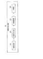
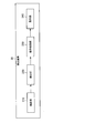
- FIG. 1 is a diagram illustrating an outline of an information processing system according to a first embodiment of the present disclosure. It is a block diagram showing the example of functional composition of the manual cutout device concerning the embodiment. It is a block diagram showing the example of functional composition of the automatic logging device concerning the embodiment.
- FIG. 3 is a block diagram illustrating a functional configuration example of a detection device according to the same embodiment. It is a flow chart which shows a flow of processing by a manual cutout device concerning the embodiment. It is a flowchart which shows the flow of a process by the automatic extraction apparatus which concerns on the embodiment. It is a figure showing the flow of generation of the automatic cutout image concerning the embodiment. It is a figure showing an example of a network structure of an automatic cutout device concerning the embodiment.
- FIG. 13 is a block diagram illustrating a functional configuration of a detection device according to a third embodiment of the present disclosure. It is a flowchart which shows the flow of the parameter update process of the detector by the detection apparatus which concerns on the same embodiment.
- FIG. 2 is a diagram illustrating a hardware configuration example according to an embodiment of the present disclosure.
- Patent Documents 1 and 2 For this reason, a method of automatically generating a learning image has been proposed, as in Patent Documents 1 and 2 described above.
- Patent Literature 2 when a synthetic image generated by CG is used as a learning image, it may be difficult to sufficiently improve the performance of the detector due to a deviation from reality.
- Patent Literature 1 discloses a technique of repeating a single machine learning method using the cut-out image generated as described above, but such a method causes a bias in learning, and causes a generalized problem. It is difficult to generate a detector with high chemical performance.
- the information processing method is based on the processor automatically cutting out a region including a target from a material image, generating an automatically cut out image, and based on the automatically cut out image.
- generating the automatic cutout image includes generating an automatic cutout image by using an automatic cutout device generated by learning based on a manual cutout image obtained by manually cutting out a region including a target from a material image. , Is further included.
- FIG. 1 is a diagram illustrating an outline of an information processing system according to the first embodiment of the present disclosure.
- the information processing system according to the present embodiment may include a manual cutout device 10, an automatic cutout device 20, and a detection device 30.
- FIG. 1 shows an example in which the detection device 30 detects a pedestrian as an object.
- the manual cutout device 10 is an information processing device that performs machine learning for realizing an automatic cutout function provided in the automatic cutout device 20.
- the manual cutout device 10 according to the present embodiment can be, for example, a PC (Personal Computer).
- the manual cutout unit 120 of the manual cutout device 10 generates a manual cutout image MTI obtained by cutting out a region including a pedestrian from a material image MI including a pedestrian, which is a target object, based on an operation by an operator. I do. That is, the operator can operate the manual clipping device 10 to trim the area where the pedestrian is reflected from the material image MI, and generate a clipped image related to the pedestrian. For example, about 16,000 manual cut-out images MTI may be generated.
- the learning unit 140 of the manual cutout device 10 performs machine learning related to the characteristics of the pedestrian based on the manually cutout image MTI cut out manually as described above.
- the learning unit 140 according to the present embodiment may perform high-performance machine learning using DNN (Deep ⁇ Neural ⁇ Network). According to the learning unit 140 according to the present embodiment, it is possible to accurately learn the characteristics of the pedestrian based on the worker, that is, the subject whose person is actually recognized as a pedestrian.
- the learned parameter P1 obtained as a result of the learning by the learning unit 140 is applied to an automatic segmenter provided in the automatic segmenter 220 of the automatic segmenter 20.
- the automatic extraction unit 220 of the automatic extraction device 20 can accurately extract an object based on the result of high-performance machine learning.
- the parameters according to the present embodiment widely include various parameters generally used in machine learning, such as weight and bias.
- the automatic cutout device 20 automatically cuts out a region including a pedestrian from the material image MI using the DNN to which the learned parameter P1 obtained as a result of the machine learning by the manual cutout device 10 is applied. It is an information processing device having a function.
- the automatic clipping unit 220 of the automatic clipping device 20 generates an automatic clipped image ATI by using a DNN to which the learned parameter P1 is applied as an automatic clipper.
- a highly accurate automatic cutout image ATI is generated in a large amount and at high speed by using the learned parameter P1 learned based on the manually cutout image MTI generated manually. It is possible to do.
- the automatic cutout unit 220 may generate, for example, about one million automatic cutout images ATI.
- the learning unit 240 of the automatic cutout device 20 performs the machine learning of a medium level of performance related to the detection of the pedestrian by using the automatically cutout image ATI automatically generated by the automatic cutout unit 220 as an input.
- the learned parameter P2 obtained as a result of learning by the learning unit 240 is applied to a detector provided in the detection unit 320 of the detection device 30.
- the automatic extraction device 20 according to the present embodiment it is possible to generate a detector with high generalization performance at low cost by performing machine learning using a large amount of automatic extraction images ATI with high extraction accuracy. Become.
- the automatic cutout device 20 according to the present embodiment can be, for example, a PC.
- the detection device 30 is an information processing device that detects a pedestrian by using a medium-performance detector to which a parameter P2 obtained as a result of machine learning by the automatic cutout device 20 is applied.
- the detection device 30 according to the present embodiment may be, for example, a camera module mounted on a vehicle.
- the detector according to the present embodiment detects a target object using HOG (Histograms of Oriented Gradients) feature amounts and SVM (Support Vector Machine).
- HOG Heistograms of Oriented Gradients
- SVM Small Vector Machine
- the detection unit 320 of the detection device 30 according to the present embodiment can detect a pedestrian in real time from an input image II captured by the imaging unit 310 described below, using the above-described detector. Further, the detection unit 320 according to the present embodiment may output a detection result as an output image OI.
- the output image OM may be displayed on, for example, a display device mounted on the vehicle.
- the detection device 30 is a camera module mounted on a vehicle and the target object to be detected is a pedestrian will be mainly described.
- the target device according to an embodiment of the present disclosure is described.
- the object and the detection device 30 are not limited to the example.
- An object according to an embodiment of the present disclosure may widely include obstacles when various moving objects including a vehicle move. Examples of the obstacle include, for example, a person including a pedestrian, another moving object, an animal, and an installed object on a moving route. Further, examples of the above-mentioned moving body include, for example, ships, aircraft including drones, and various autonomous mobile polymorphic robots.
- the detection device 30 according to an embodiment of the present disclosure may be, for example, a security camera or the like. The technical concept of the present disclosure can be widely applied to generation of various detectors that detect an object.
- FIG. 2 is a block diagram illustrating a functional configuration example of the manual cutout device 10 according to the present embodiment.
- the manual cutout device 10 according to the present embodiment includes an image supply unit 110, a manual cutout unit 120, an image storage unit 130, and a learning unit 140.
- the image supply unit 110 has a function of supplying a material image having a target as a subject to the manual cutout unit 120.
- the image supply unit 110 may supply, for example, a material image registered in advance manually by the manual cutout unit 120. Further, the image supply unit 110 can supply the material image automatically supplied from the Internet to the manual cutout unit 120, for example.
- the manual cutout unit 120 has a function of cutting out a region including a target object from a material image based on an operation by an operator and generating a manually cutout image.
- the manual cutout unit 120 according to the present embodiment may provide, for example, an operator with an image editing interface capable of performing a trimming operation or the like.
- the image storage unit 130 stores the manually cutout image generated by the manual cutout unit 120.
- the learning unit 140 performs machine learning on the characteristics of the target object by using the manually cut image generated by the manual cutout unit 120 and stored by the image storage unit 130 as an input. As described above, the learning unit 140 according to the present embodiment may perform machine learning using DNN or the like. The learned parameters obtained as a result of the learning by the learning unit 140 are applied to the automatic segmenter provided in the automatic segmenter 20.
- the functional configuration example of the manual cutout device 10 according to the present embodiment has been described above.
- the configuration described above with reference to FIG. 2 is merely an example, and the functional configuration of the manual cutout device 10 according to the present embodiment is not limited to the example.
- the functional configuration of the manual cutout device 10 according to the present embodiment can be flexibly modified according to specifications and operations.
- FIG. 3 is a block diagram illustrating a functional configuration example of the automatic cutout device 20 according to the present embodiment.
- the automatic clipping device 20 according to the present embodiment includes an image supply unit 210, an automatic clipping unit 220, an image storage unit 230, and a learning unit 240.
- the image supply unit 210 has a function of supplying the automatic cutout unit 220 with a material image of a target object.
- the image supply unit 210 may supply a material image registered in advance manually or a material image automatically supplied from the Internet to the automatic cutout unit 220.
- the automatic cutout unit 220 has a function of automatically cutting out a region including a target from a material image and generating an automatically cutout image. As described above, the automatic cutout unit 220 according to the present embodiment generates an automatic cutout image using an automatic cutout device to which learned parameters obtained as a result of machine learning by the manual cutout device 10 are applied. One of the features. Details of the function of the automatic cutout unit 220 according to the present embodiment will be separately described later.
- the image storage unit 230 stores the automatic cutout image generated by the automatic cutout unit 220.
- the learning unit 240 performs machine learning related to detection of a target object by using the automatically extracted image generated by the automatic extraction unit 220 and stored by the image storage unit 230 as an input.
- the learning unit 240 according to the present embodiment may perform machine learning using the HOG feature amount and SVM.
- the learned parameters obtained as a result of learning by the learning unit 240 are applied to a detector provided in the detection device 30.
- the functional configuration example of the automatic cutout device 20 according to the present embodiment has been described.
- the configuration described above with reference to FIG. 3 is merely an example, and the functional configuration of the automatic cutout device 20 according to the present embodiment is not limited to the example.
- the functional configuration of the automatic cutout device 20 according to the present embodiment can be flexibly modified according to specifications and operations.
- FIG. 4 is a block diagram illustrating a functional configuration example of the detection device 30 according to the present embodiment.
- the detection device 30 according to the present embodiment includes an imaging unit 310, a detection unit 320, an operation control unit 330, and an operation unit 340.
- the image capturing section 310 has a function of capturing an image (RGB image) around the vehicle. Note that the above images include moving images and still images.
- the detection unit 320 detects a target object in real time from an image captured by the imaging unit 310 using a detector to which a learned parameter obtained as a result of learning by the automatic clipping device 20 is applied. Has functions.
- the detection unit 320 according to the present embodiment outputs the detection result of the target to the operation control unit 330.
- the detection unit 320 according to the present embodiment is realized by, for example, a microcontroller.
- the operation control unit 330 has a function of controlling the operation of the operation unit 340 based on the detection result of the target by the detection unit 320.
- the operation control unit 330 according to the present embodiment outputs an alert to the operation unit 340 or activates a brake on the operation unit 340 based on, for example, the detection unit 320 detecting an object in front of the vehicle. Is also good.
- the operation control unit 330 may cause the display device included in the operation unit 340 to display the output image OI. .
- the operation unit 340 executes various operations based on control by the operation control unit 330.
- the operation unit 340 according to the present embodiment may include, for example, an accelerator, a brake, a steering, a display device, a speaker, and the like.
- the functional configuration example of the detection device 30 according to the present embodiment has been described.
- the configuration described above with reference to FIG. 4 is merely an example, and the functional configuration of the detection device 30 according to the present embodiment is not limited to the example.
- the functional configuration of the detection device 30 according to the present embodiment can be flexibly modified according to specifications and operations.
- FIG. 5 is a flowchart illustrating a flow of processing by the manual cutout device 10 according to the present embodiment.
- the image supply unit 110 supplies a material image to the manual cutout unit 120 (S1101).
- the manual cutout unit 120 cuts out a region including the target object from the material image supplied in step S1101, based on a user operation, and generates a manually cutout image (S1102).
- the image storage unit 130 stores the manually cut-out image generated in step S1102 (S1103).
- the learning unit 140 executes learning relating to the feature of the target object by using the manually cut-out image accumulated in step S1103 as an input, and generates parameters (S1104).
- the learning unit 140 applies the learned parameters obtained in step S1104 to the automatic segmenter provided in the automatic segmentation device 20 (S1105).
- FIG. 6 is a flowchart illustrating a flow of a process performed by the automatic cutout device 20 according to the present embodiment.
- the image supply unit 210 supplies a material image to the automatic cutout unit 220 (S1201).
- the automatic cutout unit 220 automatically cuts out a region including the target object from the material image supplied in step S1201, using an automatic cutout device to which the learned parameters are applied in step S1105 in FIG. An image is generated (S1202).
- the image storage unit 230 stores the automatically cut-out image generated in step S1202 (S1203).
- the learning unit 240 executes learning related to the detection of the target object using the automatically cut-out image accumulated in step S1203 as an input, and generates parameters (S1204).
- the learning unit 240 applies the learned parameter obtained in step S1204 to the detector provided in the detection device 30 (S1205).
- FIG. 7 is a diagram showing a flow of generating an automatic cutout image according to the present embodiment.
- the generation of the automatic cutout image by the automatic cutout unit 220 according to the present embodiment is realized by two main processes.
- the automatic cutout unit 220 firstly performs an approximate region including the target object from the material image MI supplied by the image supply unit 210 by a high-speed object detection method using deep learning.
- a certain provisional region Ri is specified.
- the above-described high-speed object detection method includes, for example, SSD (Single Shot multibox Detector).
- SSD Single Shot multibox Detector
- the automatic cutout unit 220 according to the present embodiment can relatively quickly specify the approximate provisional region Ri including the target in the material image MI ( For example, when the automatic cutout device 20 is equipped with the latest GPU (Graphics Processing Unit) at the time of filing, it is within 100 msec.
- the automatic cutout unit 220 may specify a region slightly larger than the region derived by the SSD or the like as the provisional region Ri.
- the provisional region Ri using the SSD as described above, for example, it is possible to divert a parameter learned from a contest image or the like, which can be obtained from the Internet. By diverting the learned parameters as described above, the time required for learning and the cost of generating a learning image can be significantly reduced.
- the high-speed object detection method using deep learning according to the present embodiment is not limited to SSD.
- the automatic cutout unit 220 according to the present embodiment may specify the provisional region Ri using, for example, a Region RCNN (Regions WITH Convolutional Neural Networks) or YOLO (Your Only Only Look Once).
- the automatic cutout unit 220 automatically cuts out the detailed region Rd including the target object from the provisional region Ri specified by the SSD using the above-described automatic cutout device, and generates an automatically cutout image ATI.
- the detailed region Rd according to the present embodiment may be a region smaller than the provisional region Ri, and may be a rectangular region in which a region that does not include the target object is excluded as much as possible.
- the upper end of the detailed region Rd may approximately match the upper end of the pedestrian's head, and the lower end of the detailed region Rd may approximately match the lower end of the pedestrian's foot.
- one of the features of the automatic cutout unit 220 according to the present embodiment is to execute the process of specifying the provisional region Ri and the process of automatically cutting out the detailed region Rd using two different neural networks.
- the provisional region Ri which is an approximate region including the target object, is specified, and the entire material image Mi is scanned.
- the detailed region Rd can be cut out without the need, and the time required for generating the automatically cutout image ATI can be greatly reduced.
- the automatic cutout unit 220 specifies the provisional region from the material image using a high-speed object detection method such as SSD, but the material image is a continuous frame of a moving image.
- the automatic cutout unit 220 can also specify an approximate area where the target object is shown by acquiring information such as a motion vector from the continuous frames.
- FIG. 8 is a diagram illustrating an example of a network structure of the automatic segmenter according to the present embodiment. Note that the network structure shown in FIG. 8 is merely an example, and the network structure of the automatic segmenter according to the present embodiment can be flexibly modified.
- Conv indicates a “Convolution” layer
- Lrn indicates “Local Response Normalization”
- Pool indicates “Pooling”
- FC indicates a "Fully Connected” layer.
- S in each layer indicates a stride
- D indicates the number of filters.
- the activation function may be, for example, ReLU, and the Pool may be Max @ Pooling. Further, the output layer may be an identity function, and the sum of squares error may be used as the loss function.
- a cutout image in which the upper end of the head and the lower end of the foot respectively match the upper and lower ends of the image is set as a positive image, and the upper end of the head and the lower end of the foot An image shifted from the end is given as a negative image and learning is performed.
- 256.0 is given to the positive image
- 0.0 is given to the negative image, and it is determined whether or not the image is accurately cut out using the output value of 128.0 as a threshold. You may decide.
- FCN Frully Convolutional Networks
- FIG. 9 is a flowchart illustrating a flow of a process performed by the detection device 30 according to the present embodiment.
- the image capturing section 310 captures an RGB image around the vehicle (S1301).
- the detection unit 320 detects an object from the RGB image captured in step S1301, using a detector to which the learned parameters obtained as a result of the learning performed by the automatic clipping device 20 are applied (S1302). .
- the operation control unit 330 causes the operation unit 340 to execute various operations based on the detection result in step S1302 (S1303).
- the operation control unit 330 may cause the operation unit 340 to display, for example, an image indicating the detected area of the target object, or based on the detection of the target object, apply a brake or the like to the operation unit 340. May be.
- a second embodiment of the present disclosure will be described.
- the case where only the RGB images are supplied to the automatic extraction unit 220 of the automatic extraction device 20 has been described.
- a simultaneously captured distance image may be supplied to the automatic cutout unit 220 together.
- An example of the above distance image is a ToF (Time of Flight) image.
- the above-described RGB image and the distance image may be simultaneously photographed by a photographing device such as an RGB-D camera, or may be photographed by two different photographing devices installed in parallel.
- the automatic clipping unit 220 may make a determination regarding the selection of the automatic clipped image based on the distance image captured at the same time as the RGB image. That is, the learning unit 240 according to the present embodiment can perform learning based on the automatically cut-out image that is adopted based on the distance between the target object and the imaging device at the time of capturing the material image.
- FIG. 10 is a diagram illustrating a flow of a process performed by the automatic cutout device 20 according to the second embodiment of the present disclosure.
- the image supply unit 210 supplies an RGB image including a target object and a distance image captured simultaneously with the RGB image to the automatic cutout unit 220 (S2101).
- the automatic cutout unit 220 specifies a temporary area in the RGB image using a high-speed object detection method such as an SSD, and determines whether or not the distance between the target object and the imaging device is within a predetermined range based on the distance image. Is determined (S2102).
- the automatic cutout unit 220 may end the process without performing the automatic cutout on the supplied RGB image. . According to this, as described later, the efficiency of the process can be increased without unnecessary generation of an automatically cutout image that is not suitable as learning data.
- the automatic cutout unit 220 when the distance between the target object and the photographing device is within a predetermined range (S2102: Yes), the automatic cutout unit 220 generates an automatically cutout image, and the image storage unit 230 stores the automatically cutout image (S2103). ).
- the learning unit 240 executes the image to which the automatic cutout image accumulated in step S2103 is input, and generates a parameter (S2104).
- the learning unit 240 applies the learned parameter obtained in step S2104 to the detector provided in the detection device 30 (S2015).
- the above is an example of the processing flow of the automatic cutout device 20 according to the present embodiment. As described above, in the present embodiment, only the automatically cut image whose distance to the target at the time of shooting is within the predetermined range is input to the learning unit 240.
- a value is set in which the distance between the object and the photographing device is neither too short nor too far.
- the target object In an image in which the distance between the target object and the imaging device is too short, the target object often appears distorted.However, using the distorted image for learning may degrade the performance of the detector. is expected. For this reason, it is possible to ensure the performance of the generated detector by excluding an image in which the distance between the target object and the imaging device is too short based on the distance image.
- the second embodiment of the present disclosure has been described.
- the automatic clipping device 20 according to the present embodiment it is possible to generate a detector with higher generalization performance.
- the automatic cutout unit 220 according to the present embodiment performs automatic cutout from a material image only when the distance between the target object and the imaging device is within a predetermined range.
- the adoption determination timing is not limited to such an example.
- the automatic cutout unit 220 may determine the adoption of the automatic cutout image based on the distance image after generating the automatic cutout image. For example, the automatic cutout unit 220 first generates an automatic cutout image regardless of the distance, and stores the automatic cutout image in the image storage unit 230 only when the distance between the target object and the imaging device is within a predetermined range. May be. Further, at a stage before the material image is supplied to the automatic cutout unit 220, for example, the operator can roughly visually select the image.
- the detection of the object using the detector and the learning for generating the detector are performed by separate devices (that is, the automatic cutout device 20 and the detection device).
- the case performed by the device 30) has been described.
- the detection device 30 according to the present embodiment may be capable of performing self-learning based on the captured image and automatically updating the parameters of the detector.
- FIG. 11 is a block diagram illustrating a functional configuration of the detection device 40 according to the third embodiment of the present disclosure.
- the detection device 40 according to the present embodiment includes an imaging unit 410, an image supply unit 420, an automatic cutout unit 430, an image storage unit 440, a learning unit 450, a detection unit 460, an operation control unit 470, and An operation unit 480 is provided.
- the detection device 40 according to the present embodiment further has an automatic cutout function and a learning function in addition to the configuration of the detection device 30 according to the first embodiment and the second embodiment. According to the above configuration, by using an image captured as the vehicle travels as a material image, learning related to detection can be continuously performed and parameters can be updated.
- the learning unit 450 according to the present embodiment can determine whether the performance of the newly generated parameter exceeds the performance of the current parameter by using the evaluation image set. At this time, the learning unit 450 according to the present embodiment may automatically update the parameters of the detector only when the performance of the newly generated parameter exceeds the performance of the current parameter. According to the above function of the learning unit 450 according to the present embodiment, it is possible to improve the generalization performance of the detector as the vehicle travels.
- FIG. 12 is a flowchart illustrating a flow of a detector parameter updating process performed by the detection device 40 according to the present embodiment.
- the photographing unit 410 inputs a photographed image to the image supply unit 420 (S3101).
- the image supply unit 420 supplies the image input in step S3101 to the automatic cutout unit 430 as a material image (S3102).
- the automatic cutout unit 430 generates an automatic cutout image including the target object from the material image supplied in step S3102 (S3103).
- the automatic cutout unit 430 may perform the determination regarding the selection of the automatically cutout image based on the distance to the target.
- the image storage unit 440 stores the automatically cut-out image generated in step S3103 (S3104).
- the learning section 450 executes learning related to the detection of the target object by using the automatic cutout image accumulated in step S3104 as an input, and generates parameters (S3105).
- the learning unit 450 determines whether the performance of the detector is improved by the parameters newly generated in step S3105 (S3106).
- the learning unit 450 does not update the parameters of the detector, and the detection device 40 returns to step S3101.
- the learning unit 450 updates the parameters of the detector, and the detecting device 40 returns to step S3101.
- the flow of the parameter update process of the detector according to the present embodiment has been described above. According to the above-described processing by the detection device 40 according to the present embodiment, it is possible to efficiently improve the detection performance of the target object by continuously performing the learning related to the detection and updating the parameter.
- the detection device 40 may transmit the learned parameters to an external server or the like via a network.
- the server can specify a parameter that realizes the highest detection performance among the parameters collected from the plurality of detection devices 40, and distribute the parameter to each detection device 40.
- a high-performance parameter can be widely shared among the plurality of detection devices 40, and the detection devices 40 having high detection performance can be efficiently mass-produced.
- the sharing of the parameters as described above may be limited to the vehicles to be mounted and the specifications of the imaging unit 410, and may be limited to the detection devices 40 with small individual differences.
- the detection performance of the target object can be effectively improved by using only the parameters self-learned by each detection device 40.
- the function of the automatic extraction unit 430 for generating an automatically extracted image does not necessarily have to be implemented as a function of the detection device 40.
- the detection device 40 may perform learning using the automatic cutout image by transmitting the material image to the server via the network and receiving the automatic cutout image generated by the server. In this case, the power consumption of the detection device 40 can be reduced, and the size of the housing can be reduced.
- FIG. 13 is a block diagram illustrating a hardware configuration example of the automatic cutout device 20 according to an embodiment of the present disclosure.
- the automatic cutout device 20 includes, for example, a processor 871, a ROM 872, a RAM 873, a host bus 874, a bridge 875, an external bus 876, an interface 877, an input device 878, and an output device 879.
- a storage 880, a drive 881, a connection port 882, and a communication device 883 Note that the hardware configuration shown here is an example, and some of the components may be omitted. Further, components other than the components shown here may be further included.
- the processor 871 functions as, for example, an arithmetic processing device or a control device, and controls the overall operation of each component or a part thereof based on various programs recorded in the ROM 872, the RAM 873, the storage 880, or the removable recording medium 901. .
- the processor 871 includes, for example, a GPU and a CPU.
- the ROM 872 is a means for storing a program read by the processor 871, data used for calculation, and the like.
- the RAM 873 temporarily or permanently stores, for example, a program read by the processor 871 and various parameters that appropriately change when the program is executed.
- the processor 871, the ROM 872, and the RAM 873 are mutually connected, for example, via a host bus 874 capable of high-speed data transmission.
- the host bus 874 is connected to, for example, an external bus 876 having a relatively low data transmission speed via a bridge 875.
- the external bus 876 is connected to various components via an interface 877.
- Input device 8708 As the input device 878, for example, a mouse, a keyboard, a touch panel, a button, a switch, a lever, and the like are used. Further, as the input device 878, a remote controller (hereinafter, remote controller) capable of transmitting a control signal using infrared rays or other radio waves may be used. Further, the input device 878 includes a voice input device such as a microphone.
- the output device 879 transmits acquired information to a user, such as a display device such as a CRT (Cathode Ray Tube), LCD, or organic EL, an audio output device such as a speaker or a headphone, a printer, a mobile phone, or a facsimile. It is a device that can visually or audibly notify the user.
- the output device 879 according to the present disclosure includes various vibration devices capable of outputting a tactile stimulus.
- the storage 880 is a device for storing various data.
- a magnetic storage device such as a hard disk drive (HDD), a semiconductor storage device, an optical storage device, a magneto-optical storage device, or the like is used.
- the drive 881 is, for example, a device that reads information recorded on a removable recording medium 901 such as a magnetic disk, an optical disk, a magneto-optical disk, or a semiconductor memory, or writes information on the removable recording medium 901.
- a removable recording medium 901 such as a magnetic disk, an optical disk, a magneto-optical disk, or a semiconductor memory
- the removable recording medium 901 is, for example, DVD media, Blu-ray (registered trademark) media, HD DVD media, various semiconductor storage media, and the like.
- the removable recording medium 901 may be, for example, an IC card on which a non-contact type IC chip is mounted, or an electronic device.
- connection port 882 is, for example, a port for connecting an external connection device 902 such as a USB (Universal Serial Bus) port, an IEEE1394 port, a SCSI (Small Computer System Interface), an RS-232C port, or an optical audio terminal. is there.
- an external connection device 902 such as a USB (Universal Serial Bus) port, an IEEE1394 port, a SCSI (Small Computer System Interface), an RS-232C port, or an optical audio terminal. is there.
- the external connection device 902 is, for example, a printer, a portable music player, a digital camera, a digital video camera, or an IC recorder.
- the communication device 883 is a communication device for connecting to a network, for example, a communication card for wired or wireless LAN, Bluetooth (registered trademark), or WUSB (Wireless USB), a router for optical communication, and an ADSL (Asymmetric Digital). Subscriber Line) or a modem for various communications.
- a network for example, a communication card for wired or wireless LAN, Bluetooth (registered trademark), or WUSB (Wireless USB), a router for optical communication, and an ADSL (Asymmetric Digital). Subscriber Line) or a modem for various communications.
- the processor automatically cuts out a region including a target from a material image to generate an automatically cutout image, and Performing learning related to the detection of an object based on the target, and generating an automatic cutout image is generated by learning based on a manually cutout image in which a region including the target is manually cut out from the material image. And generating the automatic cutout image using the automatic cutout device.
- the information processing method it is possible to reduce costs and generate a large number of highly accurate learning images without bias.
- a non-transitory computer-readable recording medium on which the program is recorded may also be provided.
- each step related to the processing of each device in the present specification does not necessarily need to be processed in a time series in the order described in the flowchart.
- each step related to the processing of the automatic cutout device 20, the detection device 30, and the detection device 40 may be processed in an order different from the order described in the flowchart, or may be processed in parallel.
- a processor automatically cuts out a region including the target object from the material image and generates an automatically cutout image
- Performing learning related to the detection of the target object based on the automatic cutout image, Including Generating the automatic cutout image includes generating the automatic cutout image by using an automatic cutout device generated by learning based on a manual cutout image obtained by manually cutting out the region including the target from the material image.
- An information processing method further comprising: (2) The information processing method according to (1), wherein the automatic cutout device is generated based on learned parameters obtained as a result of learning by a neural network using the manually cutout image as an input.
- Generating the automatic cutout image is to specify a temporary area including the target in the material image, Automatically cutting out a detailed area including the object from the temporary area,
- the information processing method according to (2) further comprising: (4) The information processing method according to (3), wherein identifying the temporary area and automatically extracting the detailed area execute processing using different neural networks.
- identifying the temporary area includes identifying the temporary area by a high-speed object detection technique using deep learning.
- (6) The information processing method according to (4) or (5), wherein automatically cutting out the detailed region executes the automatic cutout of the detailed region using the automatic cutout device and generates the automatic cutout image.
- the learning is performed based on the automatically cut-out image selected based on a distance between the object and a photographing device at the time of photographing the material image, wherein the learning is performed.
- An information processing method according to claim 1.
- Generating the automatic cutout image includes selecting the automatic cutout image relating to the material image as learning data only when a distance between the object and the photographing device is within a predetermined range. ).
- Generating the automatic cutout image is performed only when the distance between the target object and the imaging device is within a predetermined range, and automatically cuts out the area including the target object from the material image, and performs the automatic cutout.
- the information processing method according to (7), wherein the image is generated.
- the material image includes an RGB image, Generating the automatic cut-out image, based on the distance image captured at the same time as the RGB image, to determine the adoption of the automatic cut-out image,
- (11) The information processing method according to any one of (1) to (10), wherein the object includes an obstacle when the moving object moves.
- a photographing unit that shoots a material image including a target, and an automatic cutout unit that automatically cuts out a region including the target from the material image and generates an automatically cutout image
- a learning unit that performs learning related to the detection of the target object based on the automatic cutout image
- a detection unit that detects the target object based on a result of learning by the learning unit
- the automatic cutout unit generates the automatic cutout image using an automatic cutout generated by learning based on a manual cutout image in which the region including the target is manually cut out from the material image.
Landscapes
- Engineering & Computer Science (AREA)
- Physics & Mathematics (AREA)
- Theoretical Computer Science (AREA)
- General Physics & Mathematics (AREA)
- Software Systems (AREA)
- Evolutionary Computation (AREA)
- Data Mining & Analysis (AREA)
- Artificial Intelligence (AREA)
- Mathematical Physics (AREA)
- General Engineering & Computer Science (AREA)
- Computing Systems (AREA)
- Molecular Biology (AREA)
- Health & Medical Sciences (AREA)
- General Health & Medical Sciences (AREA)
- Life Sciences & Earth Sciences (AREA)
- Computational Linguistics (AREA)
- Biophysics (AREA)
- Biomedical Technology (AREA)
- Computer Vision & Pattern Recognition (AREA)
- Multimedia (AREA)
- Medical Informatics (AREA)
- Image Analysis (AREA)
- Image Processing (AREA)
- Traffic Control Systems (AREA)
Abstract
コストを低減すると共に精度の高い学習用画像を偏りなく大量に生成する。プロセッサが、素材画像中から対象物を含む領域を自動で切り出し、自動切り出し画像を生成することと、前記自動切り出し画像に基づいて前記対象物の検出に係る学習を行うことと、を含み、前記自動切り出し画像を生成することは、前記素材画像中から前記対象物を含む領域を手動で切り出した手動切り出し画像に基づく学習により生成された自動切り出し器を用いて、前記自動切り出し画像を生成すること、をさらに含む、情報処理方法が提供される。
Description
本開示は、情報処理方法、プログラム、および情報処理システムに関する。
近年、画像中における対象物を検出し、当該検出の結果に基づいて動作を行う装置が広く普及している。また、上記のような検出機能の構築に用いる学習用画像を自動で生成する手法も提案されている。例えば、特許文献1には、知識不要の比較的単純な非パターン認識系やパターン認識系アルゴリズムを用いて、素材画像から学習用画像の切り出しを自動で行う技術が開示されている。また、例えば、特許文献2には、対象物に係る画像をCG(Computer Graphics)により生成し、検出器の学習に用いる技術が開示されている。
しかし、特許文献に開示される技術では、学習用画像の切り出しに係る精度が十分とは言えず、汎化性能が高い検出器を生成することが困難である。また、特許文献2に開示されるようなCG画像は、実空間において撮影された画像と乖離があることから、対象物の検出性能を向上させるには限界がある。
本開示によれば、プロセッサが、素材画像中から対象物を含む領域を自動で切り出し、自動切り出し画像を生成することと、前記自動切り出し画像に基づいて前記対象物の検出に係る学習を行うことと、を含み、前記自動切り出し画像を生成することは、前記素材画像中から前記対象物を含む領域を手動で切り出した手動切り出し画像に基づく学習により生成された自動切り出し器を用いて、前記自動切り出し画像を生成すること、をさらに含む、情報処理方法が提供される。
また、本開示によれば、コンピュータを、素材画像中から対象物を含む領域を自動で切り出し、自動切り出し画像を生成する自動切り出し部と、前記自動切り出し画像に基づいて前記対象物の検出に係る学習を行う学習部と、を備え、前記自動切り出し部は、前記素材画像中から前記対象物を含む領域を手動で切り出した手動切り出し画像に基づく学習により生成された自動切り出し器を用いて、前記自動切り出し画像を生成する、情報処理装置、として機能させるためのプログラムが提供される。
また、本開示によれば、対象物を含む素材画像を撮影する撮影部と、前記素材画像中から対象物を含む領域を自動で切り出し、自動切り出し画像を生成する自動切り出し部と、前記自動切り出し画像に基づいて前記対象物の検出に係る学習を行う学習部と、前記学習部による学習の結果に基づいて、前記対象物の検出を行う検出部と、を備え、前記自動切り出し部は、前記素材画像中から前記対象物を含む領域を手動で切り出した手動切り出し画像に基づく学習により生成された自動切り出し器を用いて、前記自動切り出し画像を生成する、情報処理システムが提供される。
以下に添付図面を参照しながら、本開示の好適な実施の形態について詳細に説明する。なお、本明細書及び図面において、実質的に同一の機能構成を有する構成要素については、同一の符号を付することにより重複説明を省略する。
なお、説明は以下の順序で行うものとする。
1.第1の実施形態
1.1.概要
1.2.手動切り出し装置10の機能構成例
1.3.自動切り出し装置20の機能構成例
1.4.検出装置30の機能構成例
1.5.処理の流れ
2.第2の実施形態
3.第3の実施形態
4.ハードウェア構成例
5.まとめ
1.第1の実施形態
1.1.概要
1.2.手動切り出し装置10の機能構成例
1.3.自動切り出し装置20の機能構成例
1.4.検出装置30の機能構成例
1.5.処理の流れ
2.第2の実施形態
3.第3の実施形態
4.ハードウェア構成例
5.まとめ
<1.第1の実施形態>
<<1.1.概要>>
まず、本開示の第1の実施形態の概要について説明する。上述したように、近年においては、対象物の検出結果に基づいて動作を行う装置が広く普及している。上記のような装置の一例としては、例えば、撮影された画像から歩行者や走行車両などの対象物を検出し、アラートの出力や運転補助を行う車載装置などが挙げられる。
<<1.1.概要>>
まず、本開示の第1の実施形態の概要について説明する。上述したように、近年においては、対象物の検出結果に基づいて動作を行う装置が広く普及している。上記のような装置の一例としては、例えば、撮影された画像から歩行者や走行車両などの対象物を検出し、アラートの出力や運転補助を行う車載装置などが挙げられる。
ここで、上記のような車載装置に高性能な対象物検出機能を実現させるためには、検出器の生成段階において、学習用画像として用いる対象物の切り出し画像を大量に確保することが求められる。しかし、人手により上記のような切り出し画像を作成する場合、人件費や作業時間などのコストが増大することとなる。
このために、上述した特許文献1や特許文献2のように、学習用画像を自動で生成する手法も提案されている。しかし、例えば、特許文献2に記載されるように、CGにより生成した合成画像を学習用画像とする場合、現実との乖離から検出器の性能を十分に向上させることが困難な場合がある。
また、例えば、特許文献1に開示される比較的単純な非パターン認識系やパターン認識系アルゴリズムを用いた切り出し画像の生成では、十分な切り出し精度の確保が困難であることから、例えば、歩行者の検出を行う車載装置などの高い精度が求められる装置への適用は現実的とはいえない。
さらには、特許文献1には、上記のように生成した切り出し画像を用いて単一の機械学習手法を繰り返す技術が開示されているが、このような方法では学習に偏りが生じてしまい、汎化性能が高い検出器を生成することが困難である。
本開示に係る技術思想は、上記の点に着目して発想されたものであり、コストを低減すると共に精度の高い学習用画像を偏りなく大量に生成することを可能とする。このために、本開示の一実施形態に係る情報処理方法は、プロセッサが、素材画像中から対象物を含む領域を自動で切り出し、自動切り出し画像を生成することと、当該自動切り出し画像に基づいて対象物の検出に係る学習を行うことと、を含む。また、上記自動切り出し画像を生成することは、素材画像中から対象物を含む領域を手動で切り出した手動切り出し画像に基づく学習により生成された自動切り出し器を用いて、自動切り出し画像を生成すること、をさらに含む。
図1は、本開示の第1の実施形態に係る情報処理システムの概要を示す図である。図1に示すように、本実施形態に係る情報処理システムは、手動切り出し装置10、自動切り出し装置20、および検出装置30を含み得る。また、図1においては、検出装置30が対象物として歩行者を検出する場合の一例が示されている。
(手動切り出し装置10)
本実施形態に係る手動切り出し装置10は、自動切り出し装置20に備えられる自動切り出し機能を実現するための機械学習を行う情報処理装置である。本実施形態に係る手動切り出し装置10は、例えば、PC(Personal Computer)などで有り得る。
本実施形態に係る手動切り出し装置10は、自動切り出し装置20に備えられる自動切り出し機能を実現するための機械学習を行う情報処理装置である。本実施形態に係る手動切り出し装置10は、例えば、PC(Personal Computer)などで有り得る。
本実施形態に係る手動切り出し装置10の手動切り出し部120は、作業者による操作に基づいて、対象物である歩行者を含む素材画像MIから歩行者を含む領域を切り出した手動切り出し画像MTIを生成する。すなわち、作業者は、手動切り出し装置10を操作し、素材画像MIから歩行者が映っている領域をトリミングし、当該歩行者に係る切り出し画像を生成することができる。手動切り出し画像MTIは、例えば、1万6千枚程度生成されてもよい。
また、本実施形態に係る手動切り出し装置10の学習部140は、上記のように人手により切り出された手動切り出し画像MTIに基づいて、歩行者の特徴に係る機械学習を行う。本実施形態に係る学習部140は、DNN(Deep Neural Network)を用いた高性能の機械学習を行ってよい。本実施形態に係る学習部140によれば、作業者、すなわち人が実際に歩行者であると認識した被写体に基づき、歩行者の特徴を精度高く学習することが可能である。学習部140による学習の結果として得られる学習済みパラメータP1は、自動切り出し装置20の自動切り出し部220に備えられる自動切り出し器に適用される。上記のパラメータ適用によれば、自動切り出し装置20の自動切り出し部220が、高性能の機械学習の結果に基づいて精度高く対象物の切り出しを行うことが可能となる。なお、本実施形態に係るパラメータには、例えば、重みやバイアスなど、機械学習において一般的に用いられる各種のパラメータが広く含まれる。
(自動切り出し装置20)
本実施形態に係る自動切り出し装置20は、手動切り出し装置10による機械学習の結果として得られた学習済みパラメータP1が適用されたDNNを用いて、素材画像MIから歩行者を含む領域を自動で切り出す機能を有する情報処理装置である。本実施形態に自動切り出し装置20の自動切り出し部220は、学習済みパラメータP1が適用されたDNNを自動切り出し器として用いることで、自動切り出し画像ATIの生成することを特徴の一つとする。本実施形態に係る自動切り出し部220によれば、人手により生成された手動切り出し画像MTIに基づいて学習された学習済みパラメータP1を用いることで、精度の高い自動切り出し画像ATIを大量かつ高速で生成することが可能となる。なお、自動切り出し部220は、自動切り出し画像ATIを、例えば、100万枚程度生成してもよい。
本実施形態に係る自動切り出し装置20は、手動切り出し装置10による機械学習の結果として得られた学習済みパラメータP1が適用されたDNNを用いて、素材画像MIから歩行者を含む領域を自動で切り出す機能を有する情報処理装置である。本実施形態に自動切り出し装置20の自動切り出し部220は、学習済みパラメータP1が適用されたDNNを自動切り出し器として用いることで、自動切り出し画像ATIの生成することを特徴の一つとする。本実施形態に係る自動切り出し部220によれば、人手により生成された手動切り出し画像MTIに基づいて学習された学習済みパラメータP1を用いることで、精度の高い自動切り出し画像ATIを大量かつ高速で生成することが可能となる。なお、自動切り出し部220は、自動切り出し画像ATIを、例えば、100万枚程度生成してもよい。
また、本実施形態に係る自動切り出し装置20の学習部240は、自動切り出し部220により自動生成された自動切り出し画像ATIを入力として歩行者の検出に係る中程度の性能の機械学習を行う。学習部240による学習の結果として得られる学習済みパラメータP2は、検出装置30の検出部320に備えられる検出器に適用される。本実施形態に係る自動切り出し装置20によれば、切り出し精度の高い大量の自動切り出し画像ATIを用いた機械学習を行うことで、汎化性能が高い検出器を低コストで生成することが可能となる。なお、本実施形態に係る自動切り出し装置20は、例えば、PCで有り得る。
(検出装置30)
本実施形態に係る検出装置30は、自動切り出し装置20による機械学習の結果として得られたパラメータP2を適用した中程度の性能の検出器を用いて、歩行者の検出を行う情報処理装置である。本実施形態に係る検出装置30は、例えば、車両に搭載されるカメラモジュールなどであってもよい。なお、本実施形態に係る検出器は、HOG(Histograms of Oriented Gradients)特徴量とSVM(Support Vector Machine)を用いて対象物の検出を行う。このように、本実施形態では、DNNを用いた高性能の機械学習により、SVMを用いた中程度の性能の機械学習の学習データを自動生成することで、偏りのない学習を実現することができる。
本実施形態に係る検出装置30は、自動切り出し装置20による機械学習の結果として得られたパラメータP2を適用した中程度の性能の検出器を用いて、歩行者の検出を行う情報処理装置である。本実施形態に係る検出装置30は、例えば、車両に搭載されるカメラモジュールなどであってもよい。なお、本実施形態に係る検出器は、HOG(Histograms of Oriented Gradients)特徴量とSVM(Support Vector Machine)を用いて対象物の検出を行う。このように、本実施形態では、DNNを用いた高性能の機械学習により、SVMを用いた中程度の性能の機械学習の学習データを自動生成することで、偏りのない学習を実現することができる。
本実施形態に係る検出装置30の検出部320は、上記の検出器を用いて、後述する撮影部310が撮影した入力画像IIから歩行者をリアルタイムに検出することができる。また、本実施形態に係る検出部320は、検出結果を出力画像OIとして出力してもよい。出力画像OMは、例えば、車両に搭載されるディスプレイ装置などに表示されてもよい。
以上、本実施形態に係る情報処理システムの概要について説明した。以上説明したように、本実施形態に係る情報処理方法によれば、精度の高い切り出し画像を低コストで大量に自動生成することができ、結果として汎化性能が高い検出器を生成することが可能となる。
なお、本開示では、検出装置30が車両に搭載されるカメラモジュールであり、また検出に係る対象物が歩行者である場合を主な例として説明するが、本開示の一実施形態に係る対象物や検出装置30は係る例に限定されない。本開示の一実施形態に係る対象物は、車両を含む各種の移動体の移動時における障害物を広く含んでよい。障害物の一例としては、例えば、歩行者を含む人のほか、別の移動体、動物、移動ルート上における設置物などが挙げられる。また、上記の移動体の一例としては、例えば、船舶、ドローンなどを含む航空機、各種の自律移動多型ロボットなどが挙げられる。さらには、本開示の一実施形態に係る検出装置30は、例えば、防犯カメラなどであってもよい。本開示の技術思想は、対象物の検出を行う各種の検出器の生成に広く適用され得る。
<<1.2.手動切り出し装置10の機能構成例>>
次に、本実施形態に係る手動切り出し装置10の機能構成例について詳細に説明する。図2は、本実施形態に係る手動切り出し装置10の機能構成例を示すブロック図である。図2に示すように、本実施形態に係る手動切り出し装置10は、画像供給部110、手動切り出し部120、画像蓄積部130、および学習部140を備える。
次に、本実施形態に係る手動切り出し装置10の機能構成例について詳細に説明する。図2は、本実施形態に係る手動切り出し装置10の機能構成例を示すブロック図である。図2に示すように、本実施形態に係る手動切り出し装置10は、画像供給部110、手動切り出し部120、画像蓄積部130、および学習部140を備える。
(画像供給部110)
本実施形態に係る画像供給部110は、手動切り出し部120に対象物を被写体とした素材画像を供給する機能を有する。画像供給部110は、例えば、予め人手により登録された素材画像を手動切り出し部120により供給してもよい。また、画像供給部110は、例えば、インターネット上から自動で供給した素材画像を手動切り出し部120に供給することも可能である。
本実施形態に係る画像供給部110は、手動切り出し部120に対象物を被写体とした素材画像を供給する機能を有する。画像供給部110は、例えば、予め人手により登録された素材画像を手動切り出し部120により供給してもよい。また、画像供給部110は、例えば、インターネット上から自動で供給した素材画像を手動切り出し部120に供給することも可能である。
(手動切り出し部120)
本実施形態に係る手動切り出し部120は、作業者による操作に基づいて、素材画像から対象物を含む領域を切り出し、手動切り出し画像を生成する機能を有する。このために、本実施形態に係る手動切り出し部120は、例えば、トリミング操作などが可能な画像編集インタフェースを作業者に提供してもよい。
本実施形態に係る手動切り出し部120は、作業者による操作に基づいて、素材画像から対象物を含む領域を切り出し、手動切り出し画像を生成する機能を有する。このために、本実施形態に係る手動切り出し部120は、例えば、トリミング操作などが可能な画像編集インタフェースを作業者に提供してもよい。
(画像蓄積部130)
本実施形態に係る画像蓄積部130は、手動切り出し部120により生成された手動切り出し画像を蓄積する。
本実施形態に係る画像蓄積部130は、手動切り出し部120により生成された手動切り出し画像を蓄積する。
(学習部140)
本実施形態に係る学習部140は、手動切り出し部120により生成され、画像蓄積部130により蓄積される手動切り出し画像を入力として対象物の特徴に係る機械学習を行う。上述したように、本実施形態に係る学習部140は、DNNなどを用いた機械学習を行ってよい。学習部140による学習の結果として得られた学習済みパラメータは、自動切り出し装置20に備えられる自動切り出し器に適用される。
本実施形態に係る学習部140は、手動切り出し部120により生成され、画像蓄積部130により蓄積される手動切り出し画像を入力として対象物の特徴に係る機械学習を行う。上述したように、本実施形態に係る学習部140は、DNNなどを用いた機械学習を行ってよい。学習部140による学習の結果として得られた学習済みパラメータは、自動切り出し装置20に備えられる自動切り出し器に適用される。
以上、本実施形態に係る手動切り出し装置10の機能構成例について説明した。なお、図2を用いて説明した上記の構成はあくまで一例であり、本実施形態に係る手動切り出し装置10の機能構成は係る例に限定されない。本実施形態に係る手動切り出し装置10の機能構成は、仕様や運用に応じて柔軟に変形され得る。
<<1.3.自動切り出し装置20の機能構成例>>
次に、本実施形態に係る自動切り出し装置20の機能構成例について詳細に説明する。図3は、本実施形態に係る自動切り出し装置20の機能構成例を示すブロック図である。図3に示すように、本実施形態に係る自動切り出し装置20は、画像供給部210、自動切り出し部220、画像蓄積部230、および学習部240を備える。
次に、本実施形態に係る自動切り出し装置20の機能構成例について詳細に説明する。図3は、本実施形態に係る自動切り出し装置20の機能構成例を示すブロック図である。図3に示すように、本実施形態に係る自動切り出し装置20は、画像供給部210、自動切り出し部220、画像蓄積部230、および学習部240を備える。
(画像供給部210)
本実施形態に係る画像供給部210は、自動切り出し部220に対象物を被写体とした素材画像を供給する機能を有する。画像供給部210は、予め人手により登録された素材画像や、インターネット上から自動で供給した素材画像を自動切り出し部220に供給してよい。
本実施形態に係る画像供給部210は、自動切り出し部220に対象物を被写体とした素材画像を供給する機能を有する。画像供給部210は、予め人手により登録された素材画像や、インターネット上から自動で供給した素材画像を自動切り出し部220に供給してよい。
(自動切り出し部220)
本実施形態に係る自動切り出し部220は、素材画像中から対象物を含む領域を自動で切り出し、自動切り出し画像を生成する機能を有する。上述したように、本実施形態に係る自動切り出し部220は、手動切り出し装置10による機械学習の結果として得られた学習済みパラメータを適用した自動切り出し器を用いて、自動切り出し画像を生成することを特徴の一つとする。本実施形態に係る自動切り出し部220が有する機能の詳細については、別途後述する。
本実施形態に係る自動切り出し部220は、素材画像中から対象物を含む領域を自動で切り出し、自動切り出し画像を生成する機能を有する。上述したように、本実施形態に係る自動切り出し部220は、手動切り出し装置10による機械学習の結果として得られた学習済みパラメータを適用した自動切り出し器を用いて、自動切り出し画像を生成することを特徴の一つとする。本実施形態に係る自動切り出し部220が有する機能の詳細については、別途後述する。
(画像蓄積部230)
本実施形態に係る画像蓄積部230は、自動切り出し部220により生成された自動切り出し画像を蓄積する。
本実施形態に係る画像蓄積部230は、自動切り出し部220により生成された自動切り出し画像を蓄積する。
(学習部240)
本実施形態に係る学習部240は、自動切り出し部220により生成され、画像蓄積部230により蓄積される自動切り出し画像を入力として対象物の検出に係る機械学習を行う。本実施形態に係る学習部240は、HOG特徴量とSVMなどによる機械学習を行ってよい。学習部240による学習の結果として得られた学習済みパラメータは、検出装置30に備えられる検出器に適用される。
本実施形態に係る学習部240は、自動切り出し部220により生成され、画像蓄積部230により蓄積される自動切り出し画像を入力として対象物の検出に係る機械学習を行う。本実施形態に係る学習部240は、HOG特徴量とSVMなどによる機械学習を行ってよい。学習部240による学習の結果として得られた学習済みパラメータは、検出装置30に備えられる検出器に適用される。
以上、本実施形態に係る自動切り出し装置20の機能構成例について説明した。なお、図3を用いて説明した上記の構成はあくまで一例であり、本実施形態に係る自動切り出し装置20の機能構成は係る例に限定されない。本実施形態に係る自動切り出し装置20の機能構成は、仕様や運用に応じて柔軟に変形され得る。
<<1.4.検出装置30の機能構成例>>
次に、本実施形態に係る検出装置30の機能構成例について詳細に説明する。図4は、本実施形態に係る検出装置30の機能構成例を示すブロック図である。図4に示すように、本実施形態に係る検出装置30は、撮影部310、検出部320、動作制御部330、および動作部340を備える。
次に、本実施形態に係る検出装置30の機能構成例について詳細に説明する。図4は、本実施形態に係る検出装置30の機能構成例を示すブロック図である。図4に示すように、本実施形態に係る検出装置30は、撮影部310、検出部320、動作制御部330、および動作部340を備える。
(撮影部310)
本実施形態に係る撮影部310は、車両の周囲における画像(RGB画像)を撮影する機能を有する。なお、上記の画像には、動画像および静止画像が含まれる。
本実施形態に係る撮影部310は、車両の周囲における画像(RGB画像)を撮影する機能を有する。なお、上記の画像には、動画像および静止画像が含まれる。
(検出部320)
本実施形態に係る検出部320は、自動切り出し装置20による学習の結果として得られた学習済みパラメータが適用された検出器を用いて、撮影部310が撮影した画像から対象物をリアルタイムに検出する機能を有する。本実施形態に係る検出部320は、対象物の検出結果を動作制御部330に出力する。本実施形態に係る検出部320は、例えば、マイクロコントローラにより実現される。
本実施形態に係る検出部320は、自動切り出し装置20による学習の結果として得られた学習済みパラメータが適用された検出器を用いて、撮影部310が撮影した画像から対象物をリアルタイムに検出する機能を有する。本実施形態に係る検出部320は、対象物の検出結果を動作制御部330に出力する。本実施形態に係る検出部320は、例えば、マイクロコントローラにより実現される。
(動作制御部330)
本実施形態に係る動作制御部330は、検出部320による対象物の検出結果に基づいて、動作部340の動作を制御する機能を有する。本実施形態に係る動作制御部330は、例えば、検出部320が車両の前方に対象物を検出したことに基づいて、動作部340にアラートを出力させたり、動作部340にブレーキを作動させてもよい。また、検出部320が対象物の検出結果を図1に例示したような出力画像OIとして出力する場合、動作制御部330は、動作部340が備えるディスプレイ装置に出力画像OIを表示させてもよい。
本実施形態に係る動作制御部330は、検出部320による対象物の検出結果に基づいて、動作部340の動作を制御する機能を有する。本実施形態に係る動作制御部330は、例えば、検出部320が車両の前方に対象物を検出したことに基づいて、動作部340にアラートを出力させたり、動作部340にブレーキを作動させてもよい。また、検出部320が対象物の検出結果を図1に例示したような出力画像OIとして出力する場合、動作制御部330は、動作部340が備えるディスプレイ装置に出力画像OIを表示させてもよい。
(動作部340)
本実施形態に係る動作部340は、動作制御部330による制御に基づいて各種の動作を実行する。本実施形態に係る動作部340は、例えば、アクセル、ブレーキ、ステアリング、ディスプレイ装置、スピーカなどを備えてもよい。
本実施形態に係る動作部340は、動作制御部330による制御に基づいて各種の動作を実行する。本実施形態に係る動作部340は、例えば、アクセル、ブレーキ、ステアリング、ディスプレイ装置、スピーカなどを備えてもよい。
以上、本実施形態に係る検出装置30の機能構成例について説明した。なお、図4を用いて説明した上記の構成はあくまで一例であり、本実施形態に係る検出装置30の機能構成は係る例に限定されない。本実施形態に係る検出装置30の機能構成は、仕様や運用に応じて柔軟に変形され得る。
<<1.5.処理の流れ>>
次に、本実施形態に係る手動切り出し装置10、自動切り出し装置20、検出装置30による処理の流れについて詳細に説明する。
次に、本実施形態に係る手動切り出し装置10、自動切り出し装置20、検出装置30による処理の流れについて詳細に説明する。
まず、本実施形態に係る手動切り出し装置10による処理の流れについて説明する。図5は、本実施形態に係る手動切り出し装置10による処理の流れを示すフローチャートである。
図5を参照すると、まず、画像供給部110が、手動切り出し部120に素材画像を供給する(S1101)。
次に、手動切り出し部120が、ユーザ操作に基づいて、ステップS1101において供給された素材画像から対象物を含む領域を切り出し、手動切り出し画像を生成する(S1102)。
次に、画像蓄積部130が、ステップS1102において生成された手動切り出し画像を蓄積する(S1103)。
次に、学習部140が、ステップS1103において蓄積された手動切り出し画像を入力として対象物の特徴に係る学習を実行し、パラメータを生成する(S1104)。
続いて、学習部140は、自動切り出し装置20に備えられる自動切り出し器にステップS1104において得られた学習済みパラメータを適用する(S1105)。
以上、本実施形態に係る手動切り出し装置10による処理の流れについて詳細に説明した。次に、本実施形態に係る自動切り出し装置20による処理の流れについて詳細に説明する。図6は、本実施形態に係る自動切り出し装置20による処理の流れを示すフローチャートである。
図6を参照すると、まず、画像供給部210が、自動切り出し部220に素材画像を供給する(S1201)。
次に、自動切り出し部220が、図5のステップS1105において学習済みパラメータが適用された自動切り出し器を用いて、ステップS1201において供給された素材画像から対象物を含む領域を自動で切り出し、自動切り出し画像を生成する(S1202)。
次に、画像蓄積部230が、ステップS1202において生成された自動切り出し画像を蓄積する(S1203)。
次に、学習部240が、ステップS1203において蓄積された自動切り出し画像を入力として対象物の検出に係る学習を実行し、パラメータを生成する(S1204)。
続いて、学習部240は、検出装置30に備えられる検出器にステップS1204において得られた学習済みパラメータを適用する(S1205)。
以上、本実施形態に係る自動切り出し装置20による処理の流れについて説明した。続いて、本実施形態に係る自動切り出し部220による自動切り出し画像の生成について、より詳細に説明する。
図7は、本実施形態に係る自動切り出し画像の生成の流れを示す図である。本実施形態に係る自動切り出し部220による自動切り出し画像の生成は、大きく2つの処理により実現される。
具体的には、本実施形態に係る自動切り出し部220は、まず、ディープラーニングを用いた高速物体検出手法により、画像供給部210により供給された素材画像MIから、対象物を含むおおよその領域である暫定領域Riを特定する。上記の高速物体検出手法には、例えば、SSD(Single Shot multibox Detector)が挙げられる。本実施形態に係る自動切り出し部220は、SSDのような高速物体検出手法を用いることで、素材画像MIにおいて対象物を含むおおよその暫定領域Riを比較的高速に特定することが可能である(例えば、自動切り出し装置20が、出願時における最新のGPU(Graphics Processing Unit)を搭載している場合、100msec以内)。なお、自動切り出し部220は、SSD等により導出される領域よりも少し広めの領域を暫定領域Riとして特定してよい。
また、上記のようなSSDを利用した暫定領域Riの特定には、例えば、インターネット上から取得可能な、コンテスト画像などで学習済みのパラメータを転用することが可能である。上記のような学習済みパラメータを転用することにより、学習に要する時間や、学習用画像を生成するコストを大幅に削減することができる。
なお、本実施形態に係るディープラーニングを用いた高速物体検出手法は、SSDに限定されない。本実施形態に係る自動切り出し部220は、例えば、Faster RCNN(Regions with Convolutional Neural Networks)やYOLO(You Only Look Once)などを用いて暫定領域Riの特定を行ってもよい。
次に、本実施形態に係る自動切り出し部220は、上述した自動切り出し器を用いて、SSDにより特定された暫定領域Riから対象物を含む詳細領域Rdを自動で切り出し、自動切り出し画像ATIを生成する。ここで、本実施形態に係る詳細領域Rdとは、暫定領域Riよりも小さな領域であり、かつ対象物を含まない領域を極力排除した矩形領域であってもよい。例えば、対象物が歩行者である場合、詳細領域Rdの上端は歩行者の頭部上端とおおよそ一致し、詳細領域Rdの下端は、歩行者の足の下端とおおよそ一致してよい。
このように、本実施形態に係る自動切り出し部220は、2つの異なるニューラルネットワークを用いて、暫定領域Riの特定処理と詳細領域Rdの自動切り出し処理を実行することを特徴の一つとする。
本実施形態に係る自動切り出し部220が有する上記の特徴によれば、自動切り出しの前段階として、対象物を含むおおよその領域である暫定領域Riを特定することで、素材画像Miを全走査することなく詳細領域Rdを切り出し可能となり、自動切り出し画像ATIの生成に要する時間を大幅に削減することができる。
以上、本実施形態に係る自動切り出し画像ATIの生成の流れについて詳細に説明した。なお、自動切り出し部220により上記のように生成された自動切り出し画像ATIは、図7の下段に示すように、正しい領域が切り出されているかの作業者確認を以って画像蓄積部230に蓄積されてもよい。
また、上記では、本実施形態に係る自動切り出し部220が、SSDなどの高速物体検出手法を用いて素材画像から暫定領域を特定する場合を述べたが、素材画像が動画像の連続したフレームである場合、自動切り出し部220は、当該連続したフレームから動きベクトルなどの情報を取得することで、対象物が映ったおおよその領域を特定することも可能である。
続いて、本実施形態に係る自動切り出し器のネットワーク構造について詳細に説明する。図8は、本実施形態に係る自動切り出し器のネットワーク構造例を示す図である。なお、図8に示すネットワーク構造はあくまで一例であり、本実施形態に係る自動切り出し器のネットワーク構造は柔軟に変形可能である。
図8における「Conv」は「Convolution」層を、「Lrn」は「局所応答正規化(Local response normalization)を、「Pool」は「Pooling」を、「FC」は「Fully Connected」層をそれぞれ示している。また、各層における「S」はストライドを、「D」はフィルタ数をそれぞれ示している。
なお、活性化関数には例えばReLUを、Poolingには、Max Poolingを採用してもよい。また、出力層は恒等関数とし、損失関数には2乗和誤差を用いてもよい。
以上、本実施形態に係る自動切り出し器のネットワーク構成について一例を示した。本実施形態では、上記のようなネットワークに、頭部の上端と足の下端とが画像の上下端にそれぞれ一致する切り出し画像をポジティブ画像として、頭部の上端と足の下端とが画像の上下端とずれている画像をネガティブ画像として与え学習を行わせる。この際、例えば、教示データとして、ポジティブ画像には、256.0を、ネガティブ画像には0.0をそれぞれ与え、出力値の128.0を閾値として画像が正確に切り出されているか否かを判断してもよい。
また、学習データとしては、画像内正規化を施したポジティブ画像を1万6千枚程度、同様に画像内正規化を施したネガティブ画像を20万4千枚程度与えることで、自動切り出しの精度を確保することができる。また、色や明るさ、コントラストの変化に対し寛容な自動切り出し器を生成するため、色、明るさ、コントラストをランダムに変化させるデータ拡張を行った画像を学習に用いてもよい。さらには、画像を左右方向にミラーリングするデータ拡張を行った画像を用いてもよい。上記のようなデータ拡張は、頭部や足の位置に影響を与えないことから、自動切り出しの精度を低下させることなく、学習データ数を確保することが可能である。
なお、その他のデータ拡張の一例としては、例えば、FCN(Fully Convolutional Networks)によるセグメンテーションを利用したバリエーションの増加が想定される。FCNによれば、例えば、画像中における歩行者の服の領域を特定し服の色を変えた画像を生成したり、肌の領域を特定し肌の色を変えることで人種の違いを表現した画像を生成することも可能である。また、FCNによれば、画像における背景のビルや道路などを特定した、異なる建造物等に変更することなども可能である。さらには、画像中における人の手の位置を物体検出手法を用いて特定し、鞄などを上書きすることで、素材画像のバリエーションを多様化させることも可能である。
以上、本実施形態に係る自動切り出し装置20による処理の流れについて詳細に説明した。次に、本実施形態に係る検出装置30による処理の流れについて説明する。図9は、本実施形態に係る検出装置30による処理の流れを示すフローチャートである。
図9を参照すると、まず、撮影部310が車両周囲におけるRGB画像を撮影する(S1301)。
次に、検出部320が、自動切り出し装置20による学習の結果として得られた学習済みパラメータが適用された検出器を用いて、ステップS1301において撮影されたRGB画像から対象物を検出する(S1302)。
次に、動作制御部330が、ステップS1302における検出結果に基づいて、動作部340に各種の動作を実行させる(S1303)。動作制御部330は、例えば、検出された対象物の領域を示す画像を動作部340に表示させてもよいし、対象物が検出されたことに基づいて、動作部340にブレーキなどを差動させてもよい。
<2.第2の実施形態>
次に、本開示の第2の実施形態について説明する。上述した第1の実施形態では、自動切り出し装置20の自動切り出し部220にRGB画像のみが供給される場合について述べた。一方、本開示の第2の実施形態では、RGB画像に加え、同時に撮影された距離画像が併せて自動切り出し部220に供給されてよい。上記の距離画像には、例えば、ToF(Time of Flight)画像が挙げられる。上記のRGB画像および距離画像は、例えば、RGB-Dカメラなどの撮影装置により同時に撮影されてもよいし、並列に設置された異なる2つの撮影装置によりそれぞれ撮影されてもよい。
次に、本開示の第2の実施形態について説明する。上述した第1の実施形態では、自動切り出し装置20の自動切り出し部220にRGB画像のみが供給される場合について述べた。一方、本開示の第2の実施形態では、RGB画像に加え、同時に撮影された距離画像が併せて自動切り出し部220に供給されてよい。上記の距離画像には、例えば、ToF(Time of Flight)画像が挙げられる。上記のRGB画像および距離画像は、例えば、RGB-Dカメラなどの撮影装置により同時に撮影されてもよいし、並列に設置された異なる2つの撮影装置によりそれぞれ撮影されてもよい。
この際、本実施形態に係る自動切り出し部220は、RGB画像と同時に撮影された距離画像に基づいて、自動切り出し画像の採択に係る判定を行ってよい。すなわち、本実施形態に係る学習部240は、素材画像の撮影時における対象物と撮影装置との距離に基づいて採択された自動切り出し画像に基づいて学習を行うことができる。
以下、本実施形態に係る距離画像を用いた自動切り出し画像の採択について詳細に説明する。なお、以下においては、第1の実施形態との差異について中心に述べ、共通する機能や効果については重複する説明を省略する。
図10は、本開示の第2の実施形態に係る自動切り出し装置20による処理の流れを示す図である。
図10を参照すると、まず、画像供給部210が、対象物を含むRGB画像と当該RGB画像と同時に撮影された距離画像を自動切り出し部220に供給する(S2101)。
次に、自動切り出し部220は、SSDなどの高速物体検出手法を用いてRGB画像における暫定領域を特定し、距離画像に基づいて対象物と撮影装置との距離が所定の範囲内であるか否かを判定する(S2102)。
ここで、対象物と撮影装置との距離が所定の範囲内にない場合(S2102:No)、自動切り出し部220は、供給されたRGB画像に対する自動切り出しを行わずに処理を終了してもよい。これによれば、後述するように学習データとして適さない自動切り出し画像を不要に生成することなく処理を効率化することができる。
一方、対象物と撮影装置との距離が所定の範囲内である場合(S2102:Yes)、自動切り出し部220が自動切り出し画像を生成し、画像蓄積部230が当該自動切り出し画像を蓄積する(S2103)。
次に、学習部240は、ステップS2103において蓄積された自動切り出し画像を入力とした画像を実行し、パラメータを生成する(S2104)。
続いて、学習部240は、検出装置30に備えられる検出器にステップS2104において得られた学習済みパラメータを適用する(S2015)。
以上、本実施形態に係る自動切り出し装置20の処理の流れについて一例を示した。このように、本実施形態では、撮影時における対象物との距離が所定の範囲内にある自動切り出し画像のみが学習部240に入力される。
なお、上記の所定の範囲には、対象物と撮影装置との距離が近すぎず、かつ遠すぎない値が設定される。対象物と撮影装置との距離が近すぎる画像では、対象物が歪んで映る場合も多く想定されるが、歪みが生じている画像を学習に用いることで、検出器の性能が低下することが予測される。このため、距離画像に基づいて、対象物と撮影装置との距離が近すぎる画像を排除することで、生成される検出器の性能を確保することが可能となる。
また、対象物と撮影装置との距離が遠すぎる画像では、対象物を含む領域にノイズが多く加わることとなる。ノイズが多い画像は、検出器の性能低下を招く要因となり得る。このため、距離画像に基づいて、対象物と撮影装置との距離が遠すぎる画像を排除することで、生成される検出器の性能を確保することが可能となる。
以上、本開示の第2の実施形態について説明した。本実施形態に係る自動切り出し装置20によれば、より汎化性能の高い検出器を生成することが可能となる。なお、上記では、本実施形態に係る自動切り出し部220が、対象物と撮影装置との距離が所定の範囲内である場合にのみ、素材画像から自動切り出しを行う場合を例に説明したが、採択の判定タイミングは、係る例に限定されない。
本実施形態に係る自動切り出し部220は、例えば、自動切り出し画像を生成した後に、距離画像に基づいて、当該自動切り出し画像の採択を判定してもよい。自動切り出し部220は、例えば、まず距離に依らず自動切り出し画像の生成を行い、対象物と撮影装置との距離が所定の範囲内である場合にのみ、自動切り出し画像を画像蓄積部230に蓄積させてもよい。また、素材画像を自動切り出し部220に供給する前の段階において、例えば、作業者が目視により大まかに画像の選別を行うことも可能である。
<3.第3の実施形態>
次に、本開示の第3の実施形態について説明する。上記の第1の実施形態および第2の実施形態では、検出器を用いた対象物の検出と、検出器を生成するための学習とが、それぞれ別途の装置(すなわち、自動切り出し装置20および検出装置30)により行われる場合を述べた。一方、本開示の第3の実施形態では、単一の装置により上記の両機能を実現する構成について言及する。すなわち、本実施形態に係る検出装置30は、撮影した画像に基づいて自己学習を行い、自動的に検出器のパラメータを更新することができてよい。
次に、本開示の第3の実施形態について説明する。上記の第1の実施形態および第2の実施形態では、検出器を用いた対象物の検出と、検出器を生成するための学習とが、それぞれ別途の装置(すなわち、自動切り出し装置20および検出装置30)により行われる場合を述べた。一方、本開示の第3の実施形態では、単一の装置により上記の両機能を実現する構成について言及する。すなわち、本実施形態に係る検出装置30は、撮影した画像に基づいて自己学習を行い、自動的に検出器のパラメータを更新することができてよい。
以下、本開示の第3の実施形態に係る検出装置30が有する機能について詳細に説明する。なお、以下においては、第1の実施形態および第2の実施形態との差異について中心に述べ、第1の実施形態および第2の実施形態と共通する機能や効果については、重複する説明を省略する。
図11は、本開示の第3の実施形態に係る検出装置40の機能構成を示すブロック図である。図11に示すように、本実施形態に係る検出装置40は、撮影部410、画像供給部420、自動切り出し部430、画像蓄積部440、学習部450、検出部460、動作制御部470、および動作部480を備える。
すなわち、本実施形態に係る検出装置40は、第1の実施形態および第2の実施形態に係る検出装置30の構成に加え、自動切り出し機能および学習機能をさらに有するといえる。上記のような構成によれば、車両の走行に伴い撮影される画像を素材画像として利用することで、検出に係る学習を継続的に行いパラメータを更新し続けることができる。
なお、本実施形態に係る学習部450は、評価用画像セットを用いることで、新たに生成したパラメータの性能が現在のパラメータの性能を上回っているか否かを判定することができる。この際、本実施形態に係る学習部450は、新たに生成したパラメータの性能が現在のパラメータの性能を上回っている場合にのみ、検出器のパラメータを自動で更新してよい。本実施形態に係る学習部450が有する上記の機能によれば、走行すればするほど検出器の汎化性能を向上させることが可能となる。
図12は、本実施形態に係る検出装置40による検出器のパラメータ更新処理の流れを示すフローチャートである。図12を参照すると、まず撮影部410が、撮影した画像を画像供給部420に入力する(S3101)。
次に、画像供給部420が、ステップS3101において入力された画像を素材画像として自動切り出し部430に供給する(S3102)。
次に、自動切り出し部430が、ステップS3102において供給された素材画像から対象物を含む自動切り出し画像を生成する(S3103)。この際、自動切り出し部430は、第2の実施形態で説明したように、対象物までの距離に基づいて自動切り出し画像の採択に係る判定を行ってもよい。
次に、画像蓄積部440が、ステップS3103において生成された自動切り出し画像を蓄積する(S3104)。
次に、学習部450が、ステップS3104において蓄積された自動切り出し画像を入力として対象物の検出に係る学習を実行し、パラメータを生成する(S3105)。
続いて、学習部450は、評価用画像セットに基づいて、ステップS3105において新たに生成したパラメータにより検出器の性能が向上するか否かを判定する(S3106)。
ここで、新たに生成したパラメータにより検出器の性能が向上しないと判定した場合(S3106:No)、学習部450は検出器のパラメータを更新を行わず、検出装置40はステップS3101に復帰する。
一方、新たに生成したパラメータにより検出器の性能が向上すると判定した場合(S3106:Yes)、学習部450は検出器のパラメータを更新し、検出装置40はステップS3101に復帰する。
以上、本実施形態に係る検出器のパラメータ更新処理の流れについて説明した。本実施形態に係る検出装置40による上記の処理によれば、検出に係る学習を継続的に行いパラメータを更新することで、対象物の検出性能を効率的に向上させることが可能となる。
なお、本実施形態に係る検出装置40は、学習したパラメータを、ネットワークを介して外部のサーバなどに送信してもよい。この場合、上記サーバは、複数の検出装置40から収集したパラメータのうち最も高い検出性能を実現するパラメータを特定し、当該パラメータを、各検出装置40に配布することができる。このような構成によれば、複数の検出装置40の間で、性能が高いパラメータを広く共有することができ、検出性能の高い検出装置40を効率的に量産することが可能となる。
一方、上記のようなパラメータの共有は、搭載される車両や撮影部410の仕様が共通しており、また個体差が少ない検出装置40の間に限定されてよい。搭載される車両や撮影部410の個体差が大きい場合には、各検出装置40で自己学習したパラメータのみを用いることで、対象物の検出性能を効果的に向上させることができる。
なお、検出装置40が、ネットワークを介して外部のサーバなどと通信を行う場合、自動切り出し部430が有する自動切り出し画像の生成機能は、必ずしも検出装置40の機能として実現されなくてもよい。例えば、検出装置40は、ネットワークを介して上記サーバに素材画像を送信し、上記サーバにより生成された自動切り出し画像を受信することで、当該自動切り出し画像を用いた学習を行ってもよい。この場合、検出装置40の電力消費を低減し、また筐体の小型化を実現することができる。
<4.ハードウェア構成例>
次に、本開示の一実施形態に係る自動切り出し装置20のハードウェア構成例について説明する。図13は、本開示の一実施形態に係る自動切り出し装置20のハードウェア構成例を示すブロック図である。図13を参照すると、自動切り出し装置20は、例えば、プロセッサ871と、ROM872と、RAM873と、ホストバス874と、ブリッジ875と、外部バス876と、インタフェース877と、入力装置878と、出力装置879と、ストレージ880と、ドライブ881と、接続ポート882と、通信装置883と、を有する。なお、ここで示すハードウェア構成は一例であり、構成要素の一部が省略されてもよい。また、ここで示される構成要素以外の構成要素をさらに含んでもよい。
次に、本開示の一実施形態に係る自動切り出し装置20のハードウェア構成例について説明する。図13は、本開示の一実施形態に係る自動切り出し装置20のハードウェア構成例を示すブロック図である。図13を参照すると、自動切り出し装置20は、例えば、プロセッサ871と、ROM872と、RAM873と、ホストバス874と、ブリッジ875と、外部バス876と、インタフェース877と、入力装置878と、出力装置879と、ストレージ880と、ドライブ881と、接続ポート882と、通信装置883と、を有する。なお、ここで示すハードウェア構成は一例であり、構成要素の一部が省略されてもよい。また、ここで示される構成要素以外の構成要素をさらに含んでもよい。
(プロセッサ871)
プロセッサ871は、例えば、演算処理装置又は制御装置として機能し、ROM872、RAM873、ストレージ880、又はリムーバブル記録媒体901に記録された各種プログラムに基づいて各構成要素の動作全般又はその一部を制御する。プロセッサ871は、例えば、GPUやCPUを含む。
プロセッサ871は、例えば、演算処理装置又は制御装置として機能し、ROM872、RAM873、ストレージ880、又はリムーバブル記録媒体901に記録された各種プログラムに基づいて各構成要素の動作全般又はその一部を制御する。プロセッサ871は、例えば、GPUやCPUを含む。
(ROM872、RAM873)
ROM872は、プロセッサ871に読み込まれるプログラムや演算に用いるデータ等を格納する手段である。RAM873には、例えば、プロセッサ871に読み込まれるプログラムや、そのプログラムを実行する際に適宜変化する各種パラメータ等が一時的又は永続的に格納される。
ROM872は、プロセッサ871に読み込まれるプログラムや演算に用いるデータ等を格納する手段である。RAM873には、例えば、プロセッサ871に読み込まれるプログラムや、そのプログラムを実行する際に適宜変化する各種パラメータ等が一時的又は永続的に格納される。
(ホストバス874、ブリッジ875、外部バス876、インタフェース877)
プロセッサ871、ROM872、RAM873は、例えば、高速なデータ伝送が可能なホストバス874を介して相互に接続される。一方、ホストバス874は、例えば、ブリッジ875を介して比較的データ伝送速度が低速な外部バス876に接続される。また、外部バス876は、インタフェース877を介して種々の構成要素と接続される。
プロセッサ871、ROM872、RAM873は、例えば、高速なデータ伝送が可能なホストバス874を介して相互に接続される。一方、ホストバス874は、例えば、ブリッジ875を介して比較的データ伝送速度が低速な外部バス876に接続される。また、外部バス876は、インタフェース877を介して種々の構成要素と接続される。
(入力装置878)
入力装置878には、例えば、マウス、キーボード、タッチパネル、ボタン、スイッチ、及びレバー等が用いられる。さらに、入力装置878としては、赤外線やその他の電波を利用して制御信号を送信することが可能なリモートコントローラ(以下、リモコン)が用いられることもある。また、入力装置878には、マイクロフォンなどの音声入力装置が含まれる。
入力装置878には、例えば、マウス、キーボード、タッチパネル、ボタン、スイッチ、及びレバー等が用いられる。さらに、入力装置878としては、赤外線やその他の電波を利用して制御信号を送信することが可能なリモートコントローラ(以下、リモコン)が用いられることもある。また、入力装置878には、マイクロフォンなどの音声入力装置が含まれる。
(出力装置879)
出力装置879は、例えば、CRT(Cathode Ray Tube)、LCD、又は有機EL等のディスプレイ装置、スピーカ、ヘッドホン等のオーディオ出力装置、プリンタ、携帯電話、又はファクシミリ等、取得した情報を利用者に対して視覚的又は聴覚的に通知することが可能な装置である。また、本開示に係る出力装置879は、触覚刺激を出力することが可能な種々の振動デバイスを含む。
出力装置879は、例えば、CRT(Cathode Ray Tube)、LCD、又は有機EL等のディスプレイ装置、スピーカ、ヘッドホン等のオーディオ出力装置、プリンタ、携帯電話、又はファクシミリ等、取得した情報を利用者に対して視覚的又は聴覚的に通知することが可能な装置である。また、本開示に係る出力装置879は、触覚刺激を出力することが可能な種々の振動デバイスを含む。
(ストレージ880)
ストレージ880は、各種のデータを格納するための装置である。ストレージ880としては、例えば、ハードディスクドライブ(HDD)等の磁気記憶デバイス、半導体記憶デバイス、光記憶デバイス、又は光磁気記憶デバイス等が用いられる。
ストレージ880は、各種のデータを格納するための装置である。ストレージ880としては、例えば、ハードディスクドライブ(HDD)等の磁気記憶デバイス、半導体記憶デバイス、光記憶デバイス、又は光磁気記憶デバイス等が用いられる。
(ドライブ881)
ドライブ881は、例えば、磁気ディスク、光ディスク、光磁気ディスク、又は半導体メモリ等のリムーバブル記録媒体901に記録された情報を読み出し、又はリムーバブル記録媒体901に情報を書き込む装置である。
ドライブ881は、例えば、磁気ディスク、光ディスク、光磁気ディスク、又は半導体メモリ等のリムーバブル記録媒体901に記録された情報を読み出し、又はリムーバブル記録媒体901に情報を書き込む装置である。
(リムーバブル記録媒体901)リムーバブル記録媒体901は、例えば、DVDメディア、Blu-ray(登録商標)メディア、HD DVDメディア、各種の半導体記憶メディア等である。もちろん、リムーバブル記録媒体901は、例えば、非接触型ICチップを搭載したICカード、又は電子機器等であってもよい。
(接続ポート882)
接続ポート882は、例えば、USB(Universal Serial Bus)ポート、IEEE1394ポート、SCSI(Small Computer System Interface)、RS-232Cポート、又は光オーディオ端子等のような外部接続機器902を接続するためのポートである。
接続ポート882は、例えば、USB(Universal Serial Bus)ポート、IEEE1394ポート、SCSI(Small Computer System Interface)、RS-232Cポート、又は光オーディオ端子等のような外部接続機器902を接続するためのポートである。
(外部接続機器902)
外部接続機器902は、例えば、プリンタ、携帯音楽プレーヤ、デジタルカメラ、デジタルビデオカメラ、又はICレコーダ等である。
外部接続機器902は、例えば、プリンタ、携帯音楽プレーヤ、デジタルカメラ、デジタルビデオカメラ、又はICレコーダ等である。
(通信装置883)
通信装置883は、ネットワークに接続するための通信デバイスであり、例えば、有線又は無線LAN、Bluetooth(登録商標)、又はWUSB(Wireless USB)用の通信カード、光通信用のルータ、ADSL(Asymmetric Digital Subscriber Line)用のルータ、又は各種通信用のモデム等である。
通信装置883は、ネットワークに接続するための通信デバイスであり、例えば、有線又は無線LAN、Bluetooth(登録商標)、又はWUSB(Wireless USB)用の通信カード、光通信用のルータ、ADSL(Asymmetric Digital Subscriber Line)用のルータ、又は各種通信用のモデム等である。
<5.まとめ>
以上説明したように、本開示の一実施形態に係る自動切り出し装置20よれば、プロセッサが、素材画像中から対象物を含む領域を自動で切り出し、自動切り出し画像を生成することと、自動切り出し画像に基づいて対象物の検出に係る学習を行うことと、を含み、自動切り出し画像を生成することは、素材画像中から対象物を含む領域を手動で切り出した手動切り出し画像に基づく学習により生成された自動切り出し器を用いて、上記自動切り出し画像を生成すること、をさらに含む、情報処理方法が実現される。本開示の一実施形態に係る情報処理方法によれば、コストを低減すると共に精度の高い学習用画像を偏りなく大量に生成することが可能となる。
以上説明したように、本開示の一実施形態に係る自動切り出し装置20よれば、プロセッサが、素材画像中から対象物を含む領域を自動で切り出し、自動切り出し画像を生成することと、自動切り出し画像に基づいて対象物の検出に係る学習を行うことと、を含み、自動切り出し画像を生成することは、素材画像中から対象物を含む領域を手動で切り出した手動切り出し画像に基づく学習により生成された自動切り出し器を用いて、上記自動切り出し画像を生成すること、をさらに含む、情報処理方法が実現される。本開示の一実施形態に係る情報処理方法によれば、コストを低減すると共に精度の高い学習用画像を偏りなく大量に生成することが可能となる。
以上、添付図面を参照しながら本開示の好適な実施形態について詳細に説明したが、本開示の技術的範囲はかかる例に限定されない。本開示の技術分野における通常の知識を有する者であれば、請求の範囲に記載された技術的思想の範疇内において、各種の変更例または修正例に想到し得ることは明らかであり、これらについても、当然に本開示の技術的範囲に属するものと了解される。
また、本明細書に記載された効果は、あくまで説明的または例示的なものであって限定的ではない。つまり、本開示に係る技術は、上記の効果とともに、または上記の効果に代えて、本明細書の記載から当業者には明らかな他の効果を奏しうる。
また、コンピュータに内蔵されるプロセッサ、ROMおよびRAMなどのハードウェアに、自動切り出し装置20や検出装置30、検出装置40が有する構成と同等の機能を発揮させるためのプログラムも作成可能であり、当該プログラムを記録した、コンピュータに読み取り可能な非一過性の記録媒体も提供され得る。
また、本明細書の各装置の処理に係る各ステップは、必ずしもフローチャートに記載された順序に沿って時系列に処理される必要はない。例えば、自動切り出し装置20や検出装置30、検出装置40の処理に係る各ステップは、フローチャートに記載された順序と異なる順序で処理されても、並列的に処理されてもよい。
なお、以下のような構成も本開示の技術的範囲に属する。
(1)
プロセッサが、素材画像中から対象物を含む領域を自動で切り出し、自動切り出し画像を生成することと、
前記自動切り出し画像に基づいて前記対象物の検出に係る学習を行うことと、
を含み、
前記自動切り出し画像を生成することは、前記素材画像中から前記対象物を含む領域を手動で切り出した手動切り出し画像に基づく学習により生成された自動切り出し器を用いて、前記自動切り出し画像を生成すること、
をさらに含む、情報処理方法。
(2)
前記自動切り出し器は、前記手動切り出し画像を入力としたニューラルネットワークによる学習の結果として得られた学習済みパラメータに基づいて生成される、前記(1)に記載の情報処理方法。
(3)
前記自動切り出し画像を生成することは、前記素材画像中における前記対象物を含む暫定領域を特定することと、
前記暫定領域から前記対象物を含む詳細領域を自動で切り出すことと、
をさらに含む、前記(2)に記載の情報処理方法。
(4)
前記暫定領域を特定することと、前記詳細領域を自動で切り出すことは、それぞれ異なるニューラルネットワークを用いて処理を実行する、前記(3)に記載の情報処理方法。
(5)
前記暫定領域を特定することは、ディープラーニングを用いた高速物体検出手法により前記暫定領域を特定する、前記(3)または(4)に記載の情報処理方法。
(6)
前記詳細領域を自動で切り出すことは、前記自動切り出し器を用いて前記詳細領域の自動切り出しを実行し、前記自動切り出し画像を生成する、前記(4)または(5)に記載の情報処理方法。
(7)
前記学習することは、前記素材画像の撮影時における前記対象物と撮影装置との距離に基づいて採択された前記自動切り出し画像に基づいて学習を行う、前記(1)~(6)のいずれかに記載の情報処理方法。
(8)
前記自動切り出し画像を生成することは、前記対象物と前記撮影装置との距離が所定の範囲内である場合にのみ、前記素材画像に係る前記自動切り出し画像を学習データとして採択する、前記(7)に記載の情報処理方法。
(9)
前記自動切り出し画像を生成することは、前記対象物と前記撮影装置との距離が所定の範囲内である場合にのみ、前記素材画像中から前記対象物を含む領域を自動で切り出し、前記自動切り出し画像を生成する、前記(7)に記載の情報処理方法。
(10)
前記素材画像は、RGB画像を含み、
前記自動切り出し画像を生成することは、前記RGB画像と同時に撮影された距離画像に基づいて、前記自動切り出し画像の採択に係る判定を行う、
前記(7)~(9)のいずれかに記載の情報処理方法。
(11)
前記対象物は、移動体の移動時における障害物を含む、前記(1)~(10)のいずれかに記載の情報処理方法。
(12)
コンピュータを、
素材画像中から対象物を含む領域を自動で切り出し、自動切り出し画像を生成する自動切り出し部と、
前記自動切り出し画像に基づいて前記対象物の検出に係る学習を行う学習部と、
を備え、
前記自動切り出し部は、前記素材画像中から前記対象物を含む領域を手動で切り出した手動切り出し画像に基づく学習により生成された自動切り出し器を用いて、前記自動切り出し画像を生成する、
情報処理装置、として機能させるためのプログラム。
(13)
対象物を含む素材画像を撮影する撮影部と
、 前記素材画像中から対象物を含む領域を自動で切り出し、自動切り出し画像を生成する自動切り出し部と、
前記自動切り出し画像に基づいて前記対象物の検出に係る学習を行う学習部と、
前記学習部による学習の結果に基づいて、前記対象物の検出を行う検出部と、
を備え、
前記自動切り出し部は、前記素材画像中から前記対象物を含む領域を手動で切り出した手動切り出し画像に基づく学習により生成された自動切り出し器を用いて、前記自動切り出し画像を生成する、
情報処理システム。
(1)
プロセッサが、素材画像中から対象物を含む領域を自動で切り出し、自動切り出し画像を生成することと、
前記自動切り出し画像に基づいて前記対象物の検出に係る学習を行うことと、
を含み、
前記自動切り出し画像を生成することは、前記素材画像中から前記対象物を含む領域を手動で切り出した手動切り出し画像に基づく学習により生成された自動切り出し器を用いて、前記自動切り出し画像を生成すること、
をさらに含む、情報処理方法。
(2)
前記自動切り出し器は、前記手動切り出し画像を入力としたニューラルネットワークによる学習の結果として得られた学習済みパラメータに基づいて生成される、前記(1)に記載の情報処理方法。
(3)
前記自動切り出し画像を生成することは、前記素材画像中における前記対象物を含む暫定領域を特定することと、
前記暫定領域から前記対象物を含む詳細領域を自動で切り出すことと、
をさらに含む、前記(2)に記載の情報処理方法。
(4)
前記暫定領域を特定することと、前記詳細領域を自動で切り出すことは、それぞれ異なるニューラルネットワークを用いて処理を実行する、前記(3)に記載の情報処理方法。
(5)
前記暫定領域を特定することは、ディープラーニングを用いた高速物体検出手法により前記暫定領域を特定する、前記(3)または(4)に記載の情報処理方法。
(6)
前記詳細領域を自動で切り出すことは、前記自動切り出し器を用いて前記詳細領域の自動切り出しを実行し、前記自動切り出し画像を生成する、前記(4)または(5)に記載の情報処理方法。
(7)
前記学習することは、前記素材画像の撮影時における前記対象物と撮影装置との距離に基づいて採択された前記自動切り出し画像に基づいて学習を行う、前記(1)~(6)のいずれかに記載の情報処理方法。
(8)
前記自動切り出し画像を生成することは、前記対象物と前記撮影装置との距離が所定の範囲内である場合にのみ、前記素材画像に係る前記自動切り出し画像を学習データとして採択する、前記(7)に記載の情報処理方法。
(9)
前記自動切り出し画像を生成することは、前記対象物と前記撮影装置との距離が所定の範囲内である場合にのみ、前記素材画像中から前記対象物を含む領域を自動で切り出し、前記自動切り出し画像を生成する、前記(7)に記載の情報処理方法。
(10)
前記素材画像は、RGB画像を含み、
前記自動切り出し画像を生成することは、前記RGB画像と同時に撮影された距離画像に基づいて、前記自動切り出し画像の採択に係る判定を行う、
前記(7)~(9)のいずれかに記載の情報処理方法。
(11)
前記対象物は、移動体の移動時における障害物を含む、前記(1)~(10)のいずれかに記載の情報処理方法。
(12)
コンピュータを、
素材画像中から対象物を含む領域を自動で切り出し、自動切り出し画像を生成する自動切り出し部と、
前記自動切り出し画像に基づいて前記対象物の検出に係る学習を行う学習部と、
を備え、
前記自動切り出し部は、前記素材画像中から前記対象物を含む領域を手動で切り出した手動切り出し画像に基づく学習により生成された自動切り出し器を用いて、前記自動切り出し画像を生成する、
情報処理装置、として機能させるためのプログラム。
(13)
対象物を含む素材画像を撮影する撮影部と
、 前記素材画像中から対象物を含む領域を自動で切り出し、自動切り出し画像を生成する自動切り出し部と、
前記自動切り出し画像に基づいて前記対象物の検出に係る学習を行う学習部と、
前記学習部による学習の結果に基づいて、前記対象物の検出を行う検出部と、
を備え、
前記自動切り出し部は、前記素材画像中から前記対象物を含む領域を手動で切り出した手動切り出し画像に基づく学習により生成された自動切り出し器を用いて、前記自動切り出し画像を生成する、
情報処理システム。
10 手動切り出し装置
20 自動切り出し装置
210 画像供給部
220 自動切り出し部
230 画像蓄積部
240 学習部
30 検出装置
310 撮影部
320 検出部
330 動作制御部
340 動作部
20 自動切り出し装置
210 画像供給部
220 自動切り出し部
230 画像蓄積部
240 学習部
30 検出装置
310 撮影部
320 検出部
330 動作制御部
340 動作部
Claims (13)
- プロセッサが、素材画像中から対象物を含む領域を自動で切り出し、自動切り出し画像を生成することと、
前記自動切り出し画像に基づいて前記対象物の検出に係る学習を行うことと、
を含み、
前記自動切り出し画像を生成することは、前記素材画像中から前記対象物を含む領域を手動で切り出した手動切り出し画像に基づく学習により生成された自動切り出し器を用いて、前記自動切り出し画像を生成すること、
をさらに含む、情報処理方法。 - 前記自動切り出し器は、前記手動切り出し画像を入力としたニューラルネットワークによる学習の結果として得られた学習済みパラメータに基づいて生成される、請求項1に記載の情報処理方法。
- 前記自動切り出し画像を生成することは、前記素材画像中における前記対象物を含む暫定領域を特定することと、
前記暫定領域から前記対象物を含む詳細領域を自動で切り出すことと、
をさらに含む、請求項2に記載の情報処理方法。 - 前記暫定領域を特定することと、前記詳細領域を自動で切り出すことは、それぞれ異なるニューラルネットワークを用いて処理を実行する、請求項3に記載の情報処理方法。
- 前記暫定領域を特定することは、ディープラーニングを用いた高速物体検出手法により前記暫定領域を特定する、請求項3に記載の情報処理方法。
- 前記詳細領域を自動で切り出すことは、前記自動切り出し器を用いて前記詳細領域の自動切り出しを実行し、前記自動切り出し画像を生成する、請求項4に記載の情報処理方法。
- 前記学習することは、前記素材画像の撮影時における前記対象物と撮影装置との距離に基づいて採択された前記自動切り出し画像に基づいて学習を行う、請求項1に記載の情報処理方法。
- 前記自動切り出し画像を生成することは、前記対象物と前記撮影装置との距離が所定の範囲内である場合にのみ、前記素材画像に係る前記自動切り出し画像を学習データとして採択する、請求項7に記載の情報処理方法。
- 前記自動切り出し画像を生成することは、前記対象物と前記撮影装置との距離が所定の範囲内である場合にのみ、前記素材画像中から前記対象物を含む領域を自動で切り出し、前記自動切り出し画像を生成する、請求項7に記載の情報処理方法。
- 前記素材画像は、RGB画像を含み、
前記自動切り出し画像を生成することは、前記RGB画像と同時に撮影された距離画像に基づいて、前記自動切り出し画像の採択に係る判定を行う、
請求項7に記載の情報処理方法。 - 前記対象物は、移動体の移動時における障害物を含む、請求項1に記載の情報処理方法。
- コンピュータを、
素材画像中から対象物を含む領域を自動で切り出し、自動切り出し画像を生成する自動切り出し部と、
前記自動切り出し画像に基づいて前記対象物の検出に係る学習を行う学習部と、
を備え、
前記自動切り出し部は、前記素材画像中から前記対象物を含む領域を手動で切り出した手動切り出し画像に基づく学習により生成された自動切り出し器を用いて、前記自動切り出し画像を生成する、
情報処理装置、として機能させるためのプログラム。 - 対象物を含む素材画像を撮影する撮影部と、
前記素材画像中から対象物を含む領域を自動で切り出し、自動切り出し画像を生成する自動切り出し部と、
前記自動切り出し画像に基づいて前記対象物の検出に係る学習を行う学習部と、
前記学習部による学習の結果に基づいて、前記対象物の検出を行う検出部と、
を備え、
前記自動切り出し部は、前記素材画像中から前記対象物を含む領域を手動で切り出した手動切り出し画像に基づく学習により生成された自動切り出し器を用いて、前記自動切り出し画像を生成する、
情報処理システム。
Priority Applications (1)
| Application Number | Priority Date | Filing Date | Title |
|---|---|---|---|
| US17/267,963 US11861842B2 (en) | 2018-09-18 | 2019-09-09 | Information processing method, program, and information processing system |
Applications Claiming Priority (2)
| Application Number | Priority Date | Filing Date | Title |
|---|---|---|---|
| JP2018-174000 | 2018-09-18 | ||
| JP2018174000A JP2020046858A (ja) | 2018-09-18 | 2018-09-18 | 情報処理方法、プログラム、および情報処理システム |
Publications (1)
| Publication Number | Publication Date |
|---|---|
| WO2020059564A1 true WO2020059564A1 (ja) | 2020-03-26 |
Family
ID=69887437
Family Applications (1)
| Application Number | Title | Priority Date | Filing Date |
|---|---|---|---|
| PCT/JP2019/035395 Ceased WO2020059564A1 (ja) | 2018-09-18 | 2019-09-09 | 情報処理方法、プログラム、および情報処理システム |
Country Status (3)
| Country | Link |
|---|---|
| US (1) | US11861842B2 (ja) |
| JP (1) | JP2020046858A (ja) |
| WO (1) | WO2020059564A1 (ja) |
Families Citing this family (5)
| Publication number | Priority date | Publication date | Assignee | Title |
|---|---|---|---|---|
| JP7348754B2 (ja) * | 2019-06-03 | 2023-09-21 | キヤノン株式会社 | 画像処理装置及びその制御方法、プログラム、記憶媒体 |
| JP7491755B2 (ja) * | 2020-07-13 | 2024-05-28 | 繁 塩澤 | データ生成装置、検出装置、及びプログラム |
| WO2022137476A1 (ja) | 2020-12-25 | 2022-06-30 | 三菱電機株式会社 | 物体検出装置、モニタリング装置、学習装置、及び、モデル生成方法 |
| JP7267523B1 (ja) * | 2022-05-09 | 2023-05-01 | スパイダープラス株式会社 | 詳細図切出システム、詳細図切出方法及びプログラム |
| JP2024021706A (ja) * | 2022-08-04 | 2024-02-16 | パナソニックIpマネジメント株式会社 | 監視装置および監視方法 |
Family Cites Families (13)
| Publication number | Priority date | Publication date | Assignee | Title |
|---|---|---|---|---|
| JP2014059729A (ja) | 2012-09-18 | 2014-04-03 | Toshiba Corp | 物体検出・識別装置及びその方法とその物体検出・識別に用いられる辞書データ生成方法 |
| US9418467B2 (en) | 2012-12-21 | 2016-08-16 | Honda Motor Co., Ltd. | 3D human models applied to pedestrian pose classification |
| US20220375259A1 (en) * | 2013-05-31 | 2022-11-24 | IDMission LLC | Artificial intelligence for passive liveness detection |
| US9785855B2 (en) * | 2015-12-17 | 2017-10-10 | Conduent Business Services, Llc | Coarse-to-fine cascade adaptations for license plate recognition with convolutional neural networks |
| US10353950B2 (en) * | 2016-06-28 | 2019-07-16 | Google Llc | Visual recognition using user tap locations |
| US10157441B2 (en) * | 2016-12-27 | 2018-12-18 | Automotive Research & Testing Center | Hierarchical system for detecting object with parallel architecture and hierarchical method thereof |
| US10318794B2 (en) * | 2017-04-28 | 2019-06-11 | Microsoft Technology Licensing, Llc | Intelligent auto cropping of digital images |
| US20190034734A1 (en) * | 2017-07-28 | 2019-01-31 | Qualcomm Incorporated | Object classification using machine learning and object tracking |
| US10157331B1 (en) * | 2018-03-08 | 2018-12-18 | Capital One Services, Llc | Systems and methods for image preprocessing to improve accuracy of object recognition |
| US11030486B2 (en) * | 2018-04-20 | 2021-06-08 | XNOR.ai, Inc. | Image classification through label progression |
| US10748021B2 (en) * | 2018-05-11 | 2020-08-18 | Samsung Electronics Co., Ltd. | Method of analyzing objects in images recorded by a camera of a head mounted device |
| US11074430B2 (en) * | 2018-05-29 | 2021-07-27 | Adobe Inc. | Directional assistance for centering a face in a camera field of view |
| CN109523503A (zh) * | 2018-09-11 | 2019-03-26 | 北京三快在线科技有限公司 | 一种图像裁剪的方法和装置 |
-
2018
- 2018-09-18 JP JP2018174000A patent/JP2020046858A/ja active Pending
-
2019
- 2019-09-09 US US17/267,963 patent/US11861842B2/en active Active
- 2019-09-09 WO PCT/JP2019/035395 patent/WO2020059564A1/ja not_active Ceased
Non-Patent Citations (3)
| Title |
|---|
| FUJISANX: "CNN (Automated image data cropping using CNN and openCV", STARTING MACHINE LEARNING FROM SCRATCH, 3 July 2017 (2017-07-03), pages 1 - 11, Retrieved from the Internet <URL:http://zero-ai.hatenablog.com/entry/2017/07/03/211918>> [retrieved on 20191112] * |
| KENNEDY, L. ET AL.: "Learning Crop Regions for Content-Aware Generation of Thumbnail Images", PROCEEDINGS OF THE 1ST ACM INTERNATIONAL CONFERENCE ON MULTIMEDIA RETRIEVAL (ICMR'LL, 20 April 2011 (2011-04-20), pages 1 - 8, XP055160844, ISBN: 978-1-4503-0336-1, DOI: 10.1145/1991996.1992026 * |
| WATANABE, N. ET AL.: "Recognition of Car Images Using A Multi-Layered Neural Network", IEICE TECHNICAL REPORT, vol. 93, no. 537, 25 March 1994 (1994-03-25), pages 191 - 198 * |
Also Published As
| Publication number | Publication date |
|---|---|
| JP2020046858A (ja) | 2020-03-26 |
| US20210264608A1 (en) | 2021-08-26 |
| US11861842B2 (en) | 2024-01-02 |
Similar Documents
| Publication | Publication Date | Title |
|---|---|---|
| WO2020059564A1 (ja) | 情報処理方法、プログラム、および情報処理システム | |
| EP3961485B1 (en) | Image processing method, apparatus and device, and storage medium | |
| US10198823B1 (en) | Segmentation of object image data from background image data | |
| US12406408B2 (en) | Augmented reality map curation | |
| JP7026062B2 (ja) | 機械学習によってオブジェクト分類器を訓練するためのシステム及び方法 | |
| US20200209880A1 (en) | Obstacle detection method and apparatus and robot using the same | |
| US10235605B2 (en) | Image labeling using geodesic features | |
| JP2017182129A (ja) | 情報処理装置。 | |
| JP2011134114A (ja) | パターン認識方法およびパターン認識装置 | |
| CN101930611A (zh) | 多视图面部追踪 | |
| CN103903213A (zh) | 一种拍摄方法和电子设备 | |
| JP6914724B2 (ja) | 情報処理装置、情報処理方法及びプログラム | |
| JP2021026723A (ja) | 画像処理装置、画像処理方法およびプログラム | |
| CN112926461B (zh) | 神经网络训练、行驶控制方法及装置 | |
| CN115471662A (zh) | 语义分割模型的训练方法、识别方法、装置和存储介质 | |
| CN112655021A (zh) | 图像处理方法、装置、电子设备和存储介质 | |
| US12347174B2 (en) | Information processing apparatus and information processing method for object recognition learning | |
| KR101435546B1 (ko) | 카메라와 촉각형 인터페이스를 이용한 시각 장애인 보조 시스템 | |
| CN111968176B (zh) | 头戴设备的位姿确定方法、装置、设备及存储介质 | |
| JP2020052977A (ja) | 情報処理装置、情報処理方法、およびプログラム | |
| CN113506306A (zh) | 多人抠图方法、系统、装置和存储介质 | |
| KR20210091033A (ko) | 객체 정보 추정과 가상 객체 생성을 위한 전자 장치 및 전자 장치의 동작 방법 | |
| KR20180082739A (ko) | 단일 카메라를 이용한 영상에서 움직이는 객체 검출 방법 및 시스템 | |
| KR20110052962A (ko) | 객체 인식 장치 및 방법 | |
| JP2021033752A (ja) | 出力制御装置、表示制御システム、出力制御方法およびプログラム |
Legal Events
| Date | Code | Title | Description |
|---|---|---|---|
| 121 | Ep: the epo has been informed by wipo that ep was designated in this application |
Ref document number: 19862747 Country of ref document: EP Kind code of ref document: A1 |
|
| NENP | Non-entry into the national phase |
Ref country code: DE |
|
| 122 | Ep: pct application non-entry in european phase |
Ref document number: 19862747 Country of ref document: EP Kind code of ref document: A1 |