WO2020059528A1 - タッチパネルディスプレイ付きデバイス及びその制御方法、並びにプログラム - Google Patents
タッチパネルディスプレイ付きデバイス及びその制御方法、並びにプログラム Download PDFInfo
- Publication number
- WO2020059528A1 WO2020059528A1 PCT/JP2019/035057 JP2019035057W WO2020059528A1 WO 2020059528 A1 WO2020059528 A1 WO 2020059528A1 JP 2019035057 W JP2019035057 W JP 2019035057W WO 2020059528 A1 WO2020059528 A1 WO 2020059528A1
- Authority
- WO
- WIPO (PCT)
- Prior art keywords
- touch panel
- pinch
- panel display
- image
- object area
- Prior art date
- Legal status (The legal status is an assumption and is not a legal conclusion. Google has not performed a legal analysis and makes no representation as to the accuracy of the status listed.)
- Ceased
Links
Images







Classifications
-
- G—PHYSICS
- G06—COMPUTING OR CALCULATING; COUNTING
- G06F—ELECTRIC DIGITAL DATA PROCESSING
- G06F3/00—Input arrangements for transferring data to be processed into a form capable of being handled by the computer; Output arrangements for transferring data from processing unit to output unit, e.g. interface arrangements
- G06F3/01—Input arrangements or combined input and output arrangements for interaction between user and computer
- G06F3/048—Interaction techniques based on graphical user interfaces [GUI]
- G06F3/0487—Interaction techniques based on graphical user interfaces [GUI] using specific features provided by the input device, e.g. functions controlled by the rotation of a mouse with dual sensing arrangements, or of the nature of the input device, e.g. tap gestures based on pressure sensed by a digitiser
- G06F3/0488—Interaction techniques based on graphical user interfaces [GUI] using specific features provided by the input device, e.g. functions controlled by the rotation of a mouse with dual sensing arrangements, or of the nature of the input device, e.g. tap gestures based on pressure sensed by a digitiser using a touch-screen or digitiser, e.g. input of commands through traced gestures
- G06F3/04883—Interaction techniques based on graphical user interfaces [GUI] using specific features provided by the input device, e.g. functions controlled by the rotation of a mouse with dual sensing arrangements, or of the nature of the input device, e.g. tap gestures based on pressure sensed by a digitiser using a touch-screen or digitiser, e.g. input of commands through traced gestures for inputting data by handwriting, e.g. gesture or text
-
- G—PHYSICS
- G06—COMPUTING OR CALCULATING; COUNTING
- G06F—ELECTRIC DIGITAL DATA PROCESSING
- G06F3/00—Input arrangements for transferring data to be processed into a form capable of being handled by the computer; Output arrangements for transferring data from processing unit to output unit, e.g. interface arrangements
- G06F3/01—Input arrangements or combined input and output arrangements for interaction between user and computer
- G06F3/03—Arrangements for converting the position or the displacement of a member into a coded form
- G06F3/041—Digitisers, e.g. for touch screens or touch pads, characterised by the transducing means
- G06F3/0412—Digitisers structurally integrated in a display
-
- G—PHYSICS
- G06—COMPUTING OR CALCULATING; COUNTING
- G06F—ELECTRIC DIGITAL DATA PROCESSING
- G06F3/00—Input arrangements for transferring data to be processed into a form capable of being handled by the computer; Output arrangements for transferring data from processing unit to output unit, e.g. interface arrangements
- G06F3/01—Input arrangements or combined input and output arrangements for interaction between user and computer
- G06F3/03—Arrangements for converting the position or the displacement of a member into a coded form
- G06F3/041—Digitisers, e.g. for touch screens or touch pads, characterised by the transducing means
- G06F3/0414—Digitisers, e.g. for touch screens or touch pads, characterised by the transducing means using force sensing means to determine a position
- G06F3/04146—Digitisers, e.g. for touch screens or touch pads, characterised by the transducing means using force sensing means to determine a position using pressure sensitive conductive elements delivering a boolean signal and located between crossing sensing lines, e.g. located between X and Y sensing line layers
-
- G—PHYSICS
- G06—COMPUTING OR CALCULATING; COUNTING
- G06F—ELECTRIC DIGITAL DATA PROCESSING
- G06F3/00—Input arrangements for transferring data to be processed into a form capable of being handled by the computer; Output arrangements for transferring data from processing unit to output unit, e.g. interface arrangements
- G06F3/01—Input arrangements or combined input and output arrangements for interaction between user and computer
- G06F3/048—Interaction techniques based on graphical user interfaces [GUI]
- G06F3/0484—Interaction techniques based on graphical user interfaces [GUI] for the control of specific functions or operations, e.g. selecting or manipulating an object, an image or a displayed text element, setting a parameter value or selecting a range
- G06F3/04842—Selection of displayed objects or displayed text elements
-
- G—PHYSICS
- G06—COMPUTING OR CALCULATING; COUNTING
- G06F—ELECTRIC DIGITAL DATA PROCESSING
- G06F3/00—Input arrangements for transferring data to be processed into a form capable of being handled by the computer; Output arrangements for transferring data from processing unit to output unit, e.g. interface arrangements
- G06F3/01—Input arrangements or combined input and output arrangements for interaction between user and computer
- G06F3/048—Interaction techniques based on graphical user interfaces [GUI]
- G06F3/0484—Interaction techniques based on graphical user interfaces [GUI] for the control of specific functions or operations, e.g. selecting or manipulating an object, an image or a displayed text element, setting a parameter value or selecting a range
- G06F3/04845—Interaction techniques based on graphical user interfaces [GUI] for the control of specific functions or operations, e.g. selecting or manipulating an object, an image or a displayed text element, setting a parameter value or selecting a range for image manipulation, e.g. dragging, rotation, expansion or change of colour
-
- G—PHYSICS
- G06—COMPUTING OR CALCULATING; COUNTING
- G06F—ELECTRIC DIGITAL DATA PROCESSING
- G06F3/00—Input arrangements for transferring data to be processed into a form capable of being handled by the computer; Output arrangements for transferring data from processing unit to output unit, e.g. interface arrangements
- G06F3/01—Input arrangements or combined input and output arrangements for interaction between user and computer
- G06F3/048—Interaction techniques based on graphical user interfaces [GUI]
- G06F3/0487—Interaction techniques based on graphical user interfaces [GUI] using specific features provided by the input device, e.g. functions controlled by the rotation of a mouse with dual sensing arrangements, or of the nature of the input device, e.g. tap gestures based on pressure sensed by a digitiser
- G06F3/0488—Interaction techniques based on graphical user interfaces [GUI] using specific features provided by the input device, e.g. functions controlled by the rotation of a mouse with dual sensing arrangements, or of the nature of the input device, e.g. tap gestures based on pressure sensed by a digitiser using a touch-screen or digitiser, e.g. input of commands through traced gestures
-
- G—PHYSICS
- G06—COMPUTING OR CALCULATING; COUNTING
- G06F—ELECTRIC DIGITAL DATA PROCESSING
- G06F2203/00—Indexing scheme relating to G06F3/00 - G06F3/048
- G06F2203/041—Indexing scheme relating to G06F3/041 - G06F3/045
- G06F2203/04105—Pressure sensors for measuring the pressure or force exerted on the touch surface without providing the touch position
-
- G—PHYSICS
- G06—COMPUTING OR CALCULATING; COUNTING
- G06F—ELECTRIC DIGITAL DATA PROCESSING
- G06F2203/00—Indexing scheme relating to G06F3/00 - G06F3/048
- G06F2203/048—Indexing scheme relating to G06F3/048
- G06F2203/04806—Zoom, i.e. interaction techniques or interactors for controlling the zooming operation
-
- G—PHYSICS
- G06—COMPUTING OR CALCULATING; COUNTING
- G06F—ELECTRIC DIGITAL DATA PROCESSING
- G06F2203/00—Indexing scheme relating to G06F3/00 - G06F3/048
- G06F2203/048—Indexing scheme relating to G06F3/048
- G06F2203/04808—Several contacts: gestures triggering a specific function, e.g. scrolling, zooming, right-click, when the user establishes several contacts with the surface simultaneously; e.g. using several fingers or a combination of fingers and pen
Definitions
- the present invention relates to a device with a touch panel display, a control method therefor, and a program, and more particularly to a technique for performing desired processing on an image by intuitive operation.
- a touch panel display in which a touch panel for detecting an input by a contact operation is arranged on a display has become widespread, and is used in mobile devices such as smartphones.
- Patent Literature 1 discloses a technique of picking up and saving an arbitrary object corresponding to a first multi-touch input among displayed objects, and calling up the stored object in response to a second multi-touch input. Have been.
- Patent Document 2 discloses a technique for correcting the position of a selected area in an image by dragging the selected area.
- Non-Patent Document 1 discloses a technique for automatically determining and cutting out the area of an object.
- Patent No. 5731979 US Patent No. 9575641
- the objects that can be picked up are limited to those already recognized as objects from the system, and objects that are not recognized as objects cannot be picked up.
- Patent Literature 2 has a number of steps for a user to select a desired area, and cannot perform a simple operation.
- Non-Patent Document 1 Furthermore, in the technique of Non-Patent Document 1, it is necessary to specify a rectangular range for specifying a seed point, and a simple operation cannot be realized.
- the present invention has been made in view of such circumstances, and an object of the present invention is to provide a device with a touch panel display that performs desired processing on an object in an image with a simple operation, a control method thereof, and a program. I do.
- one mode of a device with a touch panel display includes a touch panel display, an image display unit that displays an image on the touch panel display, a pinch-in operation recognition unit that recognizes a user's pinch-in operation on the touch panel display, and a pinch-in operation.
- a contact area recognizing unit that recognizes a contact area in contact with the touch panel display by an operation, and an object area occupied by an object including at least a part of the contact area with respect to the image based on the contact area recognized by the contact area recognizing unit.
- An object area determining unit an operation transition recognizing unit that recognizes a transition from the pinch-in operation to an operation other than the pinch-in operation, and an operation display unit that is displayed on the touch panel display when it recognizes that the operation has transitioned to an operation other than the pinch-in operation.
- An output action unit for performing actions on the object area to an image, a touch panel display with a device equipped with.
- an object area occupied by an object including at least a part of the contact area with respect to the image is determined, and when the operation transits from the pinch-in operation to an operation other than the pinch-in operation, the touch panel Since the action relating to the object area is performed on the image displayed on the display, desired processing can be performed on the object in the image by a simple operation.
- the operation other than the pinch-in operation is at least one of a pinch-out operation, an operation of making contact with the touch panel display non-contact, a drag operation, and an operation of making the pressing force on the touch panel display stronger than the pressing force in the pinch-in operation. Is preferred.
- a desired process can be performed on the object in the image by a series of operations from the pinch-in operation.
- the action relating to the object area is at least one of an action of copying or moving the object area, an action of recording the object area in the memory, an action of changing the orientation of the object area, and an action of enlarging or reducing the object area. Is preferred. Thereby, appropriate processing can be performed on the object in the image.
- the image is preferably a captured image obtained by the image sensor. According to this aspect, it is possible to perform a desired process on an object in the image even for an image for which the object area has not been extracted.
- one aspect of a method of controlling a device with a touch panel display includes an image display step of displaying an image on the touch panel display, a pinch-in operation recognition step of recognizing a user's pinch-in operation on the touch panel display, and a pinch-in operation.
- An area determination step an operation transition recognition step of recognizing that a transition has been made from the pinch-in operation to an operation other than the pinch-in operation, and an image displayed on the touch panel display when recognizing that a transition has been made to an operation other than the pinch-in operation
- desired processing can be performed on an object in an image by a simple operation.
- a program for causing a computer to execute the control method of the device with a touch panel display is also included in the present embodiment.
- desired processing can be performed on an object in an image by a simple operation.
- FIG. 1 is a front perspective view of the tablet PC.
- FIG. 2 is a rear perspective view of the tablet PC.
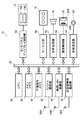
- FIG. 3 is a block diagram illustrating a system configuration of the tablet PC.
- FIG. 4 is a block diagram illustrating a system configuration of the touch panel display control unit.
- FIG. 5 is a diagram for explaining a contact area.
- FIG. 6 is a flowchart illustrating a control method of the tablet PC.
- FIG. 7 is a diagram illustrating an example in which an image is displayed on the touch panel display.
- FIG. 8 is a diagram illustrating a pinch-in operation with respect to the touch panel display.
- FIG. 9 is a diagram for explaining a transition from the pinch-in operation to an operation other than the pinch-in operation and an action related to the object area.
- FIG. 9 is a diagram for explaining a transition from the pinch-in operation to an operation other than the pinch-in operation and an action related to the object area.
- FIG. 10 is a diagram illustrating an image displayed on the touch panel display at the time when a series of operations is completed.
- FIG. 11 is a diagram for describing copying of an object between different images.
- FIG. 12 is a diagram illustrating an image displayed on the touch panel display when a series of operations is completed.
- FIG. 13 is a diagram for describing copying of an object.
- FIG. 14 is a diagram illustrating an image displayed on the touch panel display when a series of operations is completed.
- FIG. 15 is a diagram for explaining the rotation of the object.
- FIG. 16 is a diagram illustrating an image displayed on the touch panel display when a series of operations is completed.
- FIG. 17 is a diagram for explaining enlargement of an object.
- FIG. 18 is a diagram illustrating an image displayed on the touch panel display when a series of operations is completed.
- FIG. 1 is a front perspective view of a tablet computer terminal 10 (hereinafter, referred to as a tablet PC 10; PC is an abbreviation for Personal Computer) which is an example of a device with a touch panel display according to the present embodiment, and FIG. It is.
- the tablet PC 10 includes a flat casing 12 having a rectangular outline.
- the housing 12 includes a touch panel display 14, operation buttons 16, a speaker 18, a built-in camera 20, and an external connection terminal 24.
- FIG. 3 is a block diagram showing a system configuration of the tablet PC 10.
- the tablet PC 10 includes a CPU (Central Processing Unit) 30 that controls the overall operation of the tablet PC 10.
- the CPU 30 communicates with the main memory 34, the non-volatile memory 36, the mobile communication unit 38, the wireless LAN (Local Area Network) communication unit 40, the short-range wireless communication unit 42, and the wired communication via the system bus 32.
- the unit 44, the key input unit 50, the audio processing unit 52, the imaging control unit 54, and the touch panel display control unit 60 are connected.
- the CPU 30 reads an OS (Operating System) stored in the non-volatile memory 36, an application program operating on the OS, fixed data, and the like, expands the data in the main memory 34, and executes the operation program. It functions as a control unit that controls the entire operation.
- OS Operating System
- the main memory 34 is constituted by, for example, a RAM (Random Access Memory) and functions as a work memory of the CPU 30.
- the non-volatile memory 36 is formed of, for example, a flash EEPROM (Electrically Erasable Programmable Read Only Memory), and stores an OS, application programs, and various standard data.
- the nonvolatile memory 36 functions as a storage unit of the tablet PC 10 and stores various data.
- the mobile communication unit 38 communicates with the nearest wireless base station (not shown) via the antenna 38A by the fourth generation mobile communication system (4G: 4th @ Generation) or the 5th generation mobile communication system (5G: 5th @ Generation). Send and receive data.
- fourth generation mobile communication system 4G: 4th @ Generation
- 5th generation mobile communication system 5G: 5th @ Generation
- the wireless LAN communication unit 40 communicates with an external device capable of wireless LAN access point or wireless LAN communication via an antenna 40A, for example, IEEE (Institute of Electrical and Electronics Electronics) 802.11a / b / g / n standard.
- IEEE Institute of Electrical and Electronics Electronics 802.11a / b / g / n standard.
- the wireless LAN communication according to the wireless LAN communication standards such as the above is performed.
- the short-range wireless communication unit 42 communicates with another Bluetooth (registered trademark) standard device in a class 2 (within a radius of about 10 m), for example, via the antenna 42A.
- the wired communication unit 44 performs communication according to a predetermined communication standard with an external device connected via a cable (not shown) via the external connection terminal 24.
- the key input unit 50 is configured by a drive circuit that drives the plurality of operation buttons 16.
- the audio processing unit 52 converts digital audio data supplied via the system bus 32 into an analog signal.
- the analog audio signal is reproduced and output from the speaker 18.
- the imaging control unit 54 digitizes an analog image signal output from the built-in camera 20 including the imaging lens 20A and the imaging device 20B, performs necessary signal processing, and outputs the digital image signal.
- the touch panel display 14 includes a display section 14A such as a color LCD (Liquid Crystal Display) panel for displaying images and the like, a touch panel section 14B such as a transparent electrode arranged on the front surface of the color LCD panel and receiving a touch input, and a touch panel section 14B. And a pressing force sensor 14C for detecting the pressing force at the contact position of the contact.
- a display section 14A such as a color LCD (Liquid Crystal Display) panel for displaying images and the like
- a touch panel section 14B such as a transparent electrode arranged on the front surface of the color LCD panel and receiving a touch input
- a touch panel section 14B for detecting the pressing force at the contact position of the contact.
- the touch panel unit 14B is made of, for example, glass or plastic, and has a light-transmitting substrate body, a light-transmitting position detection electrode provided in a planar shape on the substrate body, and a light-transmitting position detection electrode.
- 4 is a capacitive touch panel including an insulating layer provided.
- the touch panel unit 14B is arranged on the front surface of the display unit 14A, and generates and outputs two-dimensional position coordinate information corresponding to a user's touch operation.
- the touch panel display control unit 60 controls the touch panel display 14.
- Touch panel display control section 60 associates the coordinates of the image displayed on display section 14A with the coordinates of a touch operation on touch panel section 14B.
- FIG. 4 is a block diagram showing a system configuration of the touch panel display control unit 60.
- the touch panel display control unit 60 includes a display control unit 62, an input recognition unit 68, and an image processing unit 76.
- the display control unit 62 displays various information on the display unit 14A based on a command from the CPU 30.
- the display control section 62 includes an image display section 64.
- the image display unit 64 displays various images on the display unit 14A based on a command from the CPU 30.
- the image display unit 64 causes the display unit 14A to display a captured image captured by the built-in camera 20, for example. Further, the image display unit 64 displays the image read from the nonvolatile memory 36 on the display unit 14A. Further, the image display unit 64 causes the display unit 14A to display an image acquired via the mobile communication unit 38, the wireless LAN communication unit 40, the short-range wireless communication unit 42, and the wired communication unit 44.
- the input recognition unit 68 obtains two-dimensional position coordinate information corresponding to a user's touch operation from the touch panel unit 14B and recognizes a user's input operation.
- the input recognition unit 68 includes a pinch-in motion recognition unit 70, a contact area recognition unit 72, and a motion transition recognition unit 74.
- the pinch-in operation recognition unit 70 recognizes a user's pinch-in operation on the touch panel unit 14B.
- the pinch-in operation is an operation in which, for example, a finger is brought into contact with two positions on the touch panel unit 14B, and the contact position is reduced so as to reduce the distance between the two points.
- the contact area recognition unit 72 recognizes a contact area where, for example, a finger has touched the touch panel unit 14B in the pinch-in operation.
- FIG. 5 is a diagram for explaining a contact area.
- the right index finger is moved on the touch panel display 14 from the state in which the right index finger is brought into contact with the start point PS1 located on the touch panel display 14 and the right thumb is brought into contact with the start point PS2 located on the touch panel display 14 to the end point PE1.
- the pinch-in operation is performed by moving the right thumb on the touch panel display 14 to the end point PE2.
- the contact area refers to an area A1 in which the right index finger is in contact with the touch panel display 14 from the start point PS1 to the end point PE1, and an area A2 in which the right thumb is in contact with the touch panel display 14 from the start point PS2 to the end point PE2.
- the area A1 includes a start point PS1 and an end point PE1
- the area A2 includes a start point PS2 and an end point PE2.
- the contact area refers to an area in contact with the touch panel display 14 in the pinch-in operation.
- the operation transition recognition unit 74 recognizes that the operation has transitioned from the pinch-in operation to an operation other than the pinch-in operation.
- Operations other than the pinch-in operation include, for example, a pinch-out operation, a drag operation, a rotation operation, a non-contact operation, and the like.
- the pinch-out operation is an operation in which, for example, a finger is brought into contact with two positions on the touch panel unit 14B, and the contact position is increased so as to increase the distance between the two points.
- the drag operation is an operation of moving the contact position of the touch panel unit 14B, and here includes an operation of moving the contact position while keeping the distance between the two points constant from the state of the pinch-in operation (pinch-in state).
- the rotation operation is an operation of rotating (twisting) a finger from a pinch-in state to rotate a relative positional relationship between two contact positions.
- the non-contact operation is an operation of making the contact with the touch panel unit 14B non-contact.
- the operation other than the pinch-in operation may be a pressing operation in which the pressing force on the touch panel unit 14B is relatively larger than the pressing force in the pinch-in operation.
- the image processing unit 76 performs processing on the input image.
- the image processing unit 76 includes an object area determination unit 78 and an output action unit 80.
- the object area determination unit 78 determines an object area occupied by an object including at least a part of the contact area with respect to the image displayed on the display unit 14A based on the contact area recognized by the contact area recognition unit 72.
- the output action unit 80 performs an action related to the object area on the image displayed on the display unit 14A when a transition from the pinch-in operation to an operation other than the pinch-in operation is performed.
- the display on the display unit 14A and the touch operation on the touch panel unit 14B will be simply referred to as the display on the touch panel display 14 and the operation on the touch panel display 14.
- FIG. 6 is a flowchart illustrating a control method of the tablet PC 10.
- the control method of the tablet PC 10 includes an image display step (step S1), a pinch-in motion recognition step (step S2), a contact area recognition step (step S3), and an object area determination step (step S4). ), An action transition recognition step (step S5), and an output action step (step S6).
- step S1 the image display unit 64 displays an image on the touch panel display 14.
- the user can display a desired image on the touch panel display 14 by performing a touch operation on the touch panel display 14.
- the image display unit 64 displays, for example, an image read from the nonvolatile memory 36.
- the image displayed here is one of a captured image captured using the image sensor, an image not created by a computer, and an image that has not been segmented.
- step S2 the pinch-in operation recognizing unit 70 recognizes the user's pinch-in operation on the touch panel display 14. The user performs a pinch-in operation so that at least a part of an object desired to perform a desired process among the objects included in the image displayed on the touch panel display 14 is a contact area.
- the pinch-in operation recognizing unit 70 recognizes the pinch-in operation, the process proceeds to step S3.
- step S3 the contact area recognizing unit 72 recognizes a contact area in contact with the touch panel display 14 by a pinch-in operation.
- step S4 the object area determining unit 78 determines the object area selected by the user. Specifically, an object area occupied by an object including at least a part of the contact area with respect to the image displayed on touch panel display 14 is determined based on the contact area recognized in step S3.
- the object area determination unit 78 first performs a segmentation process on the image displayed on the touch panel display 14 to extract a plurality of object areas from the image.
- the region extraction processing includes binarization (multi-value conversion) based on a pixel value distribution, graph cut for segmentation from connection between adjacent pixels, and a region expansion method (Region Growing) for extracting a region of a pixel satisfying a condition while expanding the region. ), And region extraction using a convolutional neural network (Convolutional Neural Network), but the present invention is not limited to these, and other known methods may be used.
- the object area determination unit 78 compares the position coordinate information of the contact area with the position coordinate information of the plurality of object areas, and searches for an object area including at least a part of the contact area.
- the object area determination unit 78 searches for an object area including at least a part of the contact area by performing an area extraction process by a graph cut or an area expansion method using the contact area as a seed point (foreground seed, foreground label). You may.
- the object area determination unit 78 determines that object area as the object area selected by the user. Further, when there are a plurality of object regions including at least a part of the contact region, the object region including the largest number of the contact regions may be determined as the object region selected by the user, or two contact regions (see FIG. 5). The object area including both the indicated areas A1 and A2) may be determined as the object area selected by the user.
- step S5 the operation transition recognition unit 74 recognizes that a transition has been made from the pinch-in operation to an operation other than the pinch-in operation.
- the user can perform desired processing on the selected object by shifting the touch operation on the touch panel display 14 from the pinch-in operation to an operation other than the pinch-in operation.
- the process proceeds to step S6.
- step S6 the output action unit 80 performs an action related to the object area determined in step S4 on the image displayed on the touch panel display 14, which is assigned to an operation other than the pinch-in operation in step S5.
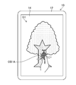
- FIG. 7 is a diagram illustrating an example in which the image G1 is displayed on the touch panel display 14.
- the image G1 is a captured image in which insects and trees are shown.
- the image G1 is an image on which no segmentation has been performed in the image.
- FIG. 8 is a diagram for explaining a pinch-in operation with respect to the touch panel display 14. As shown in FIG. 8, the pinch-in operation is performed using, for example, two fingers. In the example illustrated in FIG. 8, the user performs the pinch-in operation near the region of the image G1 where the insect is captured. More specifically, the user performs the pinch-in operation so that at least a part of the insect becomes the contact area.
- the object area determination unit 78 performs a segmentation process on the image G1 to extract an insect object area and a tree object area from the image G1. Further, the object area determining unit 78 determines an object area occupied by an object including at least a part of the contact area from the insect object area and the tree object area. In this example, the object area determination unit 78 determines the insect object area OB1A.
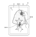
- FIG. 9 is a diagram for explaining a transition from a pinch-in operation to an operation other than the pinch-in operation and an action relating to an object area.
- the user makes a transition from the pinch-in operation to the drag operation while keeping the finger in the pinch-in state.
- the output action unit 80 sets an object which is a copy area of the insect object area OB1A and a color transparent copy area at the touch position of the finger on the touch panel display 14.
- the area OB1B is displayed.
- the user makes a transition from the drag operation to the pinch-out operation at the position where the insect is to be copied.
- the output action unit 80 copies the object area OB1C, which is a copy area of the insect object area OB1A, to the position where the pinch-out operation was performed.
- the position where the pinch-out operation has been performed is, for example, the center position of the two contact points at the starting point of the pinch-out operation. Further, the position where the pinch-out operation is performed may be the center position of the two contact positions at the end point of the pinch-out operation.
- FIG. 10 is a diagram showing an image G2 displayed on the touch panel display 14 at the time when this series of operations is completed.
- the image G2 is an image in which insects are copied and increased from the image G1 shown in FIG.
- an object in an image can be copied to a different position in the same image by a simple operation of the user. That is, the user can extract a desired object area by performing a pinch-in operation so as to touch at least a part of an object to be copied. Further, the object can be copied to a desired position in the same image simply by performing the drag operation and the pinch-out operation continuously from the pinch-in operation.
- an intuitive operation can be performed on an image for which an object area has not been extracted yet without forcing the user to perform an extra action such as performing a button operation by releasing a finger from the touch panel display.
- the operation allows the user to copy the object.
- an example in which an object in an image is copied to a different position in the same image has been described, but an object in the image may be moved to a different position in the same image.
- the original position of the moved object area may be interpolated using surrounding pixel values.
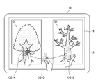
- FIG. 11 is a diagram for describing copying of an object between different images.
- the image display unit 64 displays the image G1 and the image G3 on the touch panel display 14 side by side.
- the image G1 is a captured image of an insect and a tree
- the image G3 is an image of a tree.
- the object area determining unit 78 sets the object area occupied by the object including at least a part of the contact area as the insect area, as in the case of the copy in the same image.
- the object area OB1A is determined.
- the output action unit 80 An object area OB1D, which is a copy area of the insect object area OB1A and which is a transparent copy area, is displayed.
- the drag operation here is performed from the position where the image G1 is displayed to the position where the image G3 is displayed. Further, as shown in FIG. 11, the user makes a transition to the pinch-out operation at the position of the image G3 where the object area of the insect is to be copied.
- the output action unit 80 copies the object area OB1E, which is a copy area of the insect object area OB1A, to the position where the pinch-out operation was performed.
- FIG. 12 is a diagram showing a display on the touch panel display 14 at the time when this series of operations is completed. As shown in FIG. 12, on the touch panel display 14, an image G1 and an image G4 are displayed side by side.
- the image G4 is an image in which insects are copied and increased from the image G3 shown in FIG.
- an object in an image can be copied to a desired position in a different image by a simple operation of the user.
- Objects may be moved instead of copied.
- the object area of the tree may be selected by the pinch-in operation, and the object area of the tree may be copied or moved.
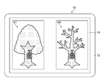
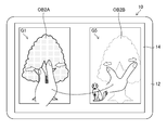
- FIG. 13 is a diagram for describing copying of an object different from the case shown in FIG.
- the image display unit 64 displays the image G1 and the image G5 on the touch panel display 14 side by side.
- the image G1 is a captured image of an insect and a tree
- the image G3 is an image of an animal.
- the user performs a pinch-in operation.
- the user performs a pinch-in operation in the vicinity of a region where the tree of the image G1 is captured. More specifically, the user performs the pinch-in operation so that at least a part of the tree becomes the contact area.
- the object area determination unit 78 determines the tree object area OB2A as an object area occupied by an object including at least a part of the contact area.
- the output action unit 80 displays a copy area of the tree object area OB2A, which is a transparent area of the color, at the contact position of the finger on the touch panel display 14. You may.
- the output action unit 80 copies the object area OB2B, which is a copy area of the tree object area OB2A, to the position where the pinch-out operation was performed.
- FIG. 14 is a diagram showing a display on the touch panel display 14 at the time when this series of operations is completed. As shown in FIG. 14, on the touch panel display 14, an image G1 and an image G6 are displayed side by side.
- the image G6 is an image in which trees are copied and increased from the image G5 shown in FIG.
- the tree is copied for each insect, but only the tree object may be copied while distinguishing the insect object from the tree object.
- the user can select a desired object area from among a plurality of objects included in the image by making the contact areas of the pinch-in operation different.
- the tablet PC 10 can change the direction of a desired object.
- FIG. 15 is a diagram for explaining the rotation of the object.
- the output action unit 80 At the touch position of the finger on the touch panel display 14, an object area OB1B, which is a copy area of the extracted object area OB1A, which is a color-transparent copy area, is displayed.
- the output action unit 80 changes and displays the direction of the object area OB1B in accordance with the rotation amount of the relative positional relationship between the two contact positions. Therefore, the user can rotate (change the direction) the extracted object by performing the rotation operation.
- the output action unit 80 copies the object area OB1B whose orientation has been changed to the position where the pinch-out operation was performed, in accordance with the transition to the pinch-out operation.
- FIG. 16 is a diagram showing an image G7 displayed on the touch panel display 14 at the time when this series of operations is completed.
- the image G7 is an image obtained by copying and increasing the insects whose orientation has been changed from the image G1 shown in FIG.
- the transition is made in the order of the drag operation, the rotation operation, and the pinch-out operation, but the same result can be obtained by making the transition in the order of the rotation operation, the drag operation, and the pinch-out operation.
- the drag operation and the pinch-out operation are not essential for the rotation operation. For example, by performing a rotation operation after a pinch-in operation and then transiting to a non-contact operation, the orientation of the determined object area can be changed at the original position, and the object whose orientation has been changed can be placed at the original position It is.
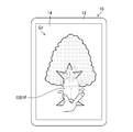
- the tablet PC 10 can also enlarge or reduce a desired object.
- FIG. 17 is a diagram for explaining enlargement of an object.
- the output action unit 80 arranges the object area OB1F obtained by enlarging the extracted object area OB1A on the touch panel display 14.
- the pinch-out operation is assigned to the output action for enlarging
- the output action to be arranged is performed by a non-contact operation.
- the assignment of actions and actions is not limited to this.
- the enlargement ratio may be changed depending on the size of the contact area of the pinch-out operation (the distance between the start point and the end point of the pinch-in operation).
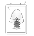
- FIG. 18 is a diagram showing an image G8 displayed on the touch panel display 14 at the time when this series of operations is completed.
- the image G8 is an image obtained by enlarging the insect from the image G1 shown in FIG.
- the user can change the size of the desired object.
- the output action unit 80 displays on the touch panel display 14 an object area obtained by reducing the extracted object area.
- the reduction ratio may be changed by the number of times of pressing or the pressing time.
- the tablet PC 10 can also store a desired object in the nonvolatile memory 36.
- the image of the object region extracted by making a transition to the non-contact operation is stored.
- the operation for storage is not limited to the non-contact operation, and may be a pinch-out operation, a pressing operation, or the like.
- an edited image of the extracted object area may be stored, such as “extraction ⁇ rotation ⁇ save” or “extraction ⁇ enlargement ⁇ save”.
- the image of the object area stored in the non-volatile memory 36 can be read out as appropriate and displayed on the touch panel display 14.
- a tablet computer terminal has been described as an example of a device with a touch panel display.
- the present invention can be applied to a mobile communication terminal such as a smartphone, a mobile phone, a PHS (Personal Handyphone System), a notebook personal computer, and the like. .
- the above-described method for controlling a device with a touch panel display is configured as a program for causing a computer to realize each step, and stores a non-temporary recording medium such as a CD-ROM (Compact Disk-Read Only Memory) storing the program. It is also possible to configure.
- a non-temporary recording medium such as a CD-ROM (Compact Disk-Read Only Memory) storing the program. It is also possible to configure.
- the hardware structure of the processing unit (processing unit) that executes various processes of the touch panel display control unit 60 is the following various processors.
- Various processors include a CPU (Central Processing Unit), which is a general-purpose processor that executes software (programs) and functions as various processing units, a GPU (Graphics Processing Unit), a processor specialized in image processing, Dedicated to execute specific processing such as Programmable Logic Device (PLD), which is a processor whose circuit configuration can be changed after manufacturing FPGA (Field Programmable Gate Array), etc., and ASIC (Application Specific Integrated Circuit).
- PLD Programmable Logic Device
- FPGA Field Programmable Gate Array
- ASIC Application Specific Integrated Circuit
- One processing unit may be configured by one of these various processors, or may be configured by two or more processors of the same type or different types (for example, a plurality of FPGAs, a combination of a CPU and an FPGA, or a combination of a CPU and a CPU). (Combination of GPUs). Further, a plurality of processing units may be configured by one processor. As an example of configuring a plurality of processing units with one processor, first, as represented by a computer such as a server and a client, one processor is configured by a combination of one or more CPUs and software. There is a form in which a processor functions as a plurality of processing units.
- SoC system-on-chip
- a form using a processor that realizes the functions of the entire system including a plurality of processing units with one integrated circuit (IC) chip is used.
- IC integrated circuit
- the various processing units are configured using one or more various processors as a hardware structure.
- circuitry circuitry in which circuit elements such as semiconductor elements are combined.
- Tablet computer terminal (tablet PC) 12 ... housing 14 ... touch panel display 14A ... display section 14B ... touch panel section 14C ... pressing force sensor 16 ... operation button 18 ... speaker 20 ... built-in camera 20A ... imaging lens 20B ... imaging element 24 ... external connection terminal 32 ... system bus 34 ... Main memory 36 ... Non-volatile memory 38 ... Mobile communication unit 38A ... Antenna 40 ... Wireless LAN communication unit 40A ... Antenna 42 ... Near field communication unit 42A ... Antenna 44 ... Wired communication unit 50 ... Key input unit 52 ...
- Sound processing unit 54 imaging control unit 60 touch panel display control unit 62 display control unit 64 image display unit 68 input recognition unit 70 pinch-in operation recognition unit 72 contact area recognition unit 74 operation transition recognition unit 76 image processing unit 78 ... Object area determining section 80.
Landscapes
- Engineering & Computer Science (AREA)
- General Engineering & Computer Science (AREA)
- Theoretical Computer Science (AREA)
- Human Computer Interaction (AREA)
- Physics & Mathematics (AREA)
- General Physics & Mathematics (AREA)
- User Interface Of Digital Computer (AREA)
Abstract
Description
図1は、本実施形態に係るタッチパネルディスプレイ付きデバイスの一例であるタブレット型コンピュータ端末10(以下、タブレットPC10と呼ぶ。PCはPersonal Computerの略)の正面斜視図であり、図2は背面斜視図である。図1及び図2に示すように、タブレットPC10は、矩形の輪郭を有する平板状の筐体12を備えている。筐体12は、タッチパネルディスプレイ14と、操作ボタン16と、スピーカ18と、内蔵カメラ20と、外部接続端子24と、を備えて構成される。
タブレットPC10は、ユーザの操作により画像内のオブジェクトについて所望の処理を行うことができる。図6は、タブレットPC10の制御方法を示すフローチャートである。図6に示すように、タブレットPC10の制御方法は、画像表示工程(ステップS1)と、ピンチイン動作認識工程(ステップS2)と、接触領域認識工程(ステップS3)と、オブジェクト領域決定工程(ステップS4)と、動作遷移認識工程(ステップS5)と、出力アクション工程(ステップS6)と、を含んでいる。
図7は、タッチパネルディスプレイ14に画像G1が表示された例を示す図である。画像G1は、昆虫と樹木が写った撮像画像である。画像G1は、画像内のセグメンテーションが行われていない画像である。
画像内のオブジェクトは、異なる画像にコピー又は移動することも可能である。
タブレットPC10は、所望のオブジェクトの向きを変更することが可能である。図15は、オブジェクトの回転について説明するための図である。
タブレットPC10は、所望のオブジェクトの拡大又は縮小を行うことも可能である。図17は、オブジェクトの拡大について説明するための図である。
タブレットPC10は、所望のオブジェクトを不揮発性メモリ36に保存することもできる。
どの「ピンチイン動作以外の動作」をどの「オブジェクト領域に関するアクション」に割り当てるかは、上記の例に限定されず、適宜決めればよい。1回のピンチイン動作というユーザの簡便な操作でオブジェクトを指定することができる点が重要である。
12…筐体
14…タッチパネルディスプレイ
14A…ディスプレイ部
14B…タッチパネル部
14C…押圧力センサ
16…操作ボタン
18…スピーカ
20…内蔵カメラ
20A…撮像レンズ
20B…撮像素子
24…外部接続端子
32…システムバス
34…メインメモリ
36…不揮発性メモリ
38…モバイル通信部
38A…アンテナ
40…無線LAN通信部
40A…アンテナ
42…近距離無線通信部
42A…アンテナ
44…有線通信部
50…キー入力部
52…音声処理部
54…撮像制御部
60…タッチパネルディスプレイ制御部
62…表示制御部
64…画像表示部
68…入力認識部
70…ピンチイン動作認識部
72…接触領域認識部
74…動作遷移認識部
76…画像処理部
78…オブジェクト領域決定部
80…出力アクション部
S1~S6…タブレットPCの制御方法の各ステップ
Claims (13)
- タッチパネルディスプレイと、
前記タッチパネルディスプレイに画像を表示させる画像表示部と、
前記タッチパネルディスプレイに対するユーザのピンチイン動作を認識するピンチイン動作認識部と、
前記ピンチイン動作によって前記タッチパネルディスプレイと接触した接触領域を認識する接触領域認識部と、
前記接触領域認識部が認識した接触領域に基づいて、前記画像に対して前記接触領域を少なくとも一部含むオブジェクトが占めるオブジェクト領域を決定するオブジェクト領域決定部と、
前記ピンチイン動作から前記ピンチイン動作以外の動作に遷移したことを認識する動作遷移認識部と、
前記ピンチイン動作以外の動作に遷移したと認識した場合に、前記タッチパネルディスプレイに表示された画像に対して前記オブジェクト領域に関するアクションを行う出力アクション部と、
を備えたタッチパネルディスプレイ付きデバイス。 - 前記ピンチイン動作以外の動作はピンチアウト動作である請求項1に記載のタッチパネルディスプレイ付きデバイス。
- 前記ピンチイン動作以外の動作は前記タッチパネルディスプレイとの接触を非接触にする動作である請求項1又は2に記載のタッチパネルディスプレイ付きデバイス。
- 前記ピンチイン動作以外の動作はドラッグ動作である請求項1から3のいずれか1項に記載のタッチパネルディスプレイ付きデバイス。
- 前記ピンチイン動作以外の動作は前記タッチパネルディスプレイに対する押圧力を前記ピンチイン動作における押圧力より強くする動作である請求項1から4のいずれか1項に記載のタッチパネルディスプレイ付きデバイス。
- 前記オブジェクト領域に関するアクションは、前記オブジェクト領域をコピー又は移動するアクションである請求項1から5のいずれか1項に記載のタッチパネルディスプレイ付きデバイス。
- 前記オブジェクト領域に関するアクションは、前記オブジェクト領域をメモリに記録させるアクションである請求項1から5のいずれか1項に記載のタッチパネルディスプレイ付きデバイス。
- 前記オブジェクト領域に関するアクションは、前記オブジェクト領域の向きを変更するアクションである請求項1から5のいずれか1項に記載のタッチパネルディスプレイ付きデバイス。
- 前記オブジェクト領域に関するアクションは、前記オブジェクト領域を拡大又は縮小させるアクションである請求項1から5のいずれか1項に記載のタッチパネルディスプレイ付きデバイス。
- 前記画像は撮像素子により得られた撮像画像である請求項1から9のいずれか1項に記載のタッチパネルディスプレイ付きデバイス。
- タッチパネルディスプレイに画像を表示させる画像表示工程と、
前記タッチパネルディスプレイに対するユーザのピンチイン動作を認識するピンチイン動作認識工程と、
前記ピンチイン動作によって前記タッチパネルディスプレイと接触した接触領域を認識する接触領域認識工程と、
前記接触領域認識工程が認識した接触領域に基づいて、前記画像に対して前記接触領域を少なくとも一部含むオブジェクトが占めるオブジェクト領域を決定するオブジェクト領域決定工程と、
前記ピンチイン動作から前記ピンチイン動作以外の動作に遷移したことを認識する動作遷移認識工程と、
前記ピンチイン動作以外の動作に遷移したと認識した場合に、前記タッチパネルディスプレイに表示された画像に対して前記オブジェクト領域に関するアクションを行う出力アクション工程と、
を備えたタッチパネルディスプレイ付きデバイスの制御方法。 - 請求項11に記載のタッチパネルディスプレイ付きデバイスの制御方法をコンピュータに実行させるためのプログラム。
- 非一時的かつコンピュータ読取可能な記録媒体であって、前記記録媒体に格納された指令がコンピュータによって読み取られた場合に請求項12に記載のプログラムをコンピュータに実行させる記録媒体。
Priority Applications (3)
| Application Number | Priority Date | Filing Date | Title |
|---|---|---|---|
| JP2020548321A JP7349441B2 (ja) | 2018-09-19 | 2019-09-05 | タッチパネルディスプレイ付きデバイス及びその制御方法、並びにプログラム |
| CN201980061151.9A CN112740163B (zh) | 2018-09-19 | 2019-09-05 | 带触摸屏显示器的器件及其控制方法 |
| US17/203,046 US11416133B2 (en) | 2018-09-19 | 2021-03-16 | Device with touch panel display, control method of device with touch panel display, and program |
Applications Claiming Priority (2)
| Application Number | Priority Date | Filing Date | Title |
|---|---|---|---|
| JP2018-175097 | 2018-09-19 | ||
| JP2018175097 | 2018-09-19 |
Related Child Applications (1)
| Application Number | Title | Priority Date | Filing Date |
|---|---|---|---|
| US17/203,046 Continuation US11416133B2 (en) | 2018-09-19 | 2021-03-16 | Device with touch panel display, control method of device with touch panel display, and program |
Publications (1)
| Publication Number | Publication Date |
|---|---|
| WO2020059528A1 true WO2020059528A1 (ja) | 2020-03-26 |
Family
ID=69887263
Family Applications (1)
| Application Number | Title | Priority Date | Filing Date |
|---|---|---|---|
| PCT/JP2019/035057 Ceased WO2020059528A1 (ja) | 2018-09-19 | 2019-09-05 | タッチパネルディスプレイ付きデバイス及びその制御方法、並びにプログラム |
Country Status (4)
| Country | Link |
|---|---|
| US (1) | US11416133B2 (ja) |
| JP (1) | JP7349441B2 (ja) |
| CN (1) | CN112740163B (ja) |
| WO (1) | WO2020059528A1 (ja) |
Families Citing this family (1)
| Publication number | Priority date | Publication date | Assignee | Title |
|---|---|---|---|---|
| TWI849948B (zh) * | 2023-06-02 | 2024-07-21 | 大陸商北京集創北方科技股份有限公司 | 觸摸區域劃分方法、電子晶片及資訊處理裝置 |
Citations (4)
| Publication number | Priority date | Publication date | Assignee | Title |
|---|---|---|---|---|
| JP2010140300A (ja) * | 2008-12-12 | 2010-06-24 | Sharp Corp | 表示装置、制御方法、制御プログラムおよび記録媒体 |
| JP2012505466A (ja) * | 2008-10-13 | 2012-03-01 | サムスン エレクトロニクス カンパニー リミテッド | タッチスクリーンを利用したオブジェクト管理方法及び装置 |
| JP2014134867A (ja) * | 2013-01-08 | 2014-07-24 | Sharp Corp | 情報処理端末 |
| JP2016001509A (ja) * | 2015-09-24 | 2016-01-07 | 京セラ株式会社 | 電子機器、制御方法および制御プログラム |
Family Cites Families (7)
| Publication number | Priority date | Publication date | Assignee | Title |
|---|---|---|---|---|
| US7382919B2 (en) * | 2006-06-22 | 2008-06-03 | Xerox Corporation | System and method for editing image data |
| CN102239470B (zh) * | 2008-12-04 | 2018-03-16 | 三菱电机株式会社 | 显示输入装置及导航装置 |
| JP5666239B2 (ja) * | 2010-10-15 | 2015-02-12 | シャープ株式会社 | 情報処理装置、情報処理装置の制御方法、プログラム、および記録媒体 |
| US9575641B2 (en) * | 2012-03-20 | 2017-02-21 | Adobe Systems Incorporated | Content aware image editing |
| CN104737104B (zh) * | 2012-10-19 | 2017-12-19 | 三菱电机株式会社 | 信息处理装置、信息终端、信息处理系统及校准方法 |
| JP6019074B2 (ja) * | 2014-09-16 | 2016-11-02 | 京セラドキュメントソリューションズ株式会社 | 電子機器、及び、タッチパネルの操作方法 |
| DK201870349A1 (en) * | 2018-01-24 | 2019-10-23 | Apple Inc. | Devices, Methods, and Graphical User Interfaces for System-Wide Behavior for 3D Models |
-
2019
- 2019-09-05 WO PCT/JP2019/035057 patent/WO2020059528A1/ja not_active Ceased
- 2019-09-05 JP JP2020548321A patent/JP7349441B2/ja active Active
- 2019-09-05 CN CN201980061151.9A patent/CN112740163B/zh active Active
-
2021
- 2021-03-16 US US17/203,046 patent/US11416133B2/en active Active
Patent Citations (4)
| Publication number | Priority date | Publication date | Assignee | Title |
|---|---|---|---|---|
| JP2012505466A (ja) * | 2008-10-13 | 2012-03-01 | サムスン エレクトロニクス カンパニー リミテッド | タッチスクリーンを利用したオブジェクト管理方法及び装置 |
| JP2010140300A (ja) * | 2008-12-12 | 2010-06-24 | Sharp Corp | 表示装置、制御方法、制御プログラムおよび記録媒体 |
| JP2014134867A (ja) * | 2013-01-08 | 2014-07-24 | Sharp Corp | 情報処理端末 |
| JP2016001509A (ja) * | 2015-09-24 | 2016-01-07 | 京セラ株式会社 | 電子機器、制御方法および制御プログラム |
Also Published As
| Publication number | Publication date |
|---|---|
| CN112740163A (zh) | 2021-04-30 |
| US20210200428A1 (en) | 2021-07-01 |
| JP7349441B2 (ja) | 2023-09-22 |
| US11416133B2 (en) | 2022-08-16 |
| CN112740163B (zh) | 2025-11-14 |
| JPWO2020059528A1 (ja) | 2021-08-30 |
Similar Documents
| Publication | Publication Date | Title |
|---|---|---|
| US12333137B2 (en) | Configuration of application execution spaces and sub-spaces for sharing data on a mobile touch screen device | |
| KR102285699B1 (ko) | 이미지를 디스플레이하는 사용자 단말기 및 이의 이미지 디스플레이 방법 | |
| CN107659722B (zh) | 一种图像选择方法及移动终端 | |
| CN107613203B (zh) | 一种图像处理方法及移动终端 | |
| WO2019185003A1 (zh) | 一种显示控制方法及设备 | |
| CN109003224B (zh) | 基于人脸的形变图像生成方法和装置 | |
| CN107172346A (zh) | 一种虚化方法及移动终端 | |
| KR20160049455A (ko) | 스크롤바를 이용한 이미지 디스플레이 방법 및 이를 위한 장치 | |
| KR20140100547A (ko) | 모바일 장치상의 풀 3d 상호작용 | |
| JP2015114997A (ja) | 図面作成プログラム、図面作成方法及び情報処理装置 | |
| JP2010102395A (ja) | 画像処理装置、画像処理方法およびプログラム | |
| CN106528080B (zh) | 一种移动终端的应用图标的放置方法和移动终端 | |
| CN106919318A (zh) | 一种图片处理的方法及终端 | |
| CN106598623A (zh) | 一种图片组合模板的生成方法及移动终端 | |
| CN106126108A (zh) | 一种缩略图的生成方法及移动终端 | |
| CN107492067A (zh) | 一种图像美化方法及移动终端 | |
| CN106354373A (zh) | 一种图标移动方法及移动终端 | |
| JP7732283B2 (ja) | 表示装置、表示システム、表示制御方法、及びプログラム | |
| CN105242853A (zh) | 一种对焦方法及电子设备 | |
| JP7349441B2 (ja) | タッチパネルディスプレイ付きデバイス及びその制御方法、並びにプログラム | |
| CN106453886A (zh) | 一种移动终端的拍照方法及移动终端 | |
| US11983877B2 (en) | Image processing device, image processing method, program, and portable terminal device | |
| CN106791775A (zh) | 一种图像处理方法和移动终端 | |
| CN106406717A (zh) | 一种屏幕调整方法及装置 | |
| JP7608874B2 (ja) | 表示装置、表示方法、プログラム |
Legal Events
| Date | Code | Title | Description |
|---|---|---|---|
| 121 | Ep: the epo has been informed by wipo that ep was designated in this application |
Ref document number: 19863509 Country of ref document: EP Kind code of ref document: A1 |
|
| ENP | Entry into the national phase |
Ref document number: 2020548321 Country of ref document: JP Kind code of ref document: A |
|
| WWE | Wipo information: entry into national phase |
Ref document number: 201980061151.9 Country of ref document: CN |
|
| NENP | Non-entry into the national phase |
Ref country code: DE |
|
| 122 | Ep: pct application non-entry in european phase |
Ref document number: 19863509 Country of ref document: EP Kind code of ref document: A1 |