WO2020059091A1 - Electrolytic capacitor - Google Patents
Electrolytic capacitor Download PDFInfo
- Publication number
- WO2020059091A1 WO2020059091A1 PCT/JP2018/034885 JP2018034885W WO2020059091A1 WO 2020059091 A1 WO2020059091 A1 WO 2020059091A1 JP 2018034885 W JP2018034885 W JP 2018034885W WO 2020059091 A1 WO2020059091 A1 WO 2020059091A1
- Authority
- WO
- WIPO (PCT)
- Prior art keywords
- electrolytic capacitor
- sealing body
- fat
- capacitor according
- electrolytic
- Prior art date
Links
- 239000003990 capacitor Substances 0.000 title claims abstract description 124
- 238000007789 sealing Methods 0.000 claims abstract description 97
- 239000011888 foil Substances 0.000 claims abstract description 78
- 239000003963 antioxidant agent Substances 0.000 claims abstract description 55
- 230000003078 antioxidant effect Effects 0.000 claims abstract description 55
- 239000002904 solvent Substances 0.000 claims abstract description 27
- 235000006708 antioxidants Nutrition 0.000 claims description 54
- 239000008151 electrolyte solution Substances 0.000 claims description 28
- 239000003792 electrolyte Substances 0.000 claims description 19
- LYCAIKOWRPUZTN-UHFFFAOYSA-N Ethylene glycol Chemical compound OCCO LYCAIKOWRPUZTN-UHFFFAOYSA-N 0.000 claims description 15
- MTHSVFCYNBDYFN-UHFFFAOYSA-N diethylene glycol Chemical compound OCCOCCO MTHSVFCYNBDYFN-UHFFFAOYSA-N 0.000 claims description 15
- YEJRWHAVMIAJKC-UHFFFAOYSA-N 4-Butyrolactone Chemical group O=C1CCCO1 YEJRWHAVMIAJKC-UHFFFAOYSA-N 0.000 claims description 14
- 239000002736 nonionic surfactant Substances 0.000 claims description 13
- GVJHHUAWPYXKBD-UHFFFAOYSA-N d-alpha-tocopherol Natural products OC1=C(C)C(C)=C2OC(CCCC(C)CCCC(C)CCCC(C)C)(C)CCC2=C1C GVJHHUAWPYXKBD-UHFFFAOYSA-N 0.000 claims description 12
- 239000007784 solid electrolyte Substances 0.000 claims description 12
- 239000000243 solution Substances 0.000 claims description 10
- 229940088594 vitamin Drugs 0.000 claims description 10
- 229930003231 vitamin Natural products 0.000 claims description 10
- 235000013343 vitamin Nutrition 0.000 claims description 10
- 239000011782 vitamin Substances 0.000 claims description 10
- -1 polyethylene Polymers 0.000 claims description 8
- 229930003799 tocopherol Natural products 0.000 claims description 8
- 239000011732 tocopherol Substances 0.000 claims description 8
- 229960001295 tocopherol Drugs 0.000 claims description 8
- 235000010384 tocopherol Nutrition 0.000 claims description 8
- GVJHHUAWPYXKBD-IEOSBIPESA-N α-tocopherol Chemical compound OC1=C(C)C(C)=C2O[C@@](CCC[C@H](C)CCC[C@H](C)CCCC(C)C)(C)CCC2=C1C GVJHHUAWPYXKBD-IEOSBIPESA-N 0.000 claims description 8
- 150000003722 vitamin derivatives Chemical class 0.000 claims description 7
- GJJVAFUKOBZPCB-UHFFFAOYSA-N 2-methyl-2-(4,8,12-trimethyltrideca-3,7,11-trienyl)-3,4-dihydrochromen-6-ol Chemical compound OC1=CC=C2OC(CCC=C(C)CCC=C(C)CCC=C(C)C)(C)CCC2=C1 GJJVAFUKOBZPCB-UHFFFAOYSA-N 0.000 claims description 5
- 239000004698 Polyethylene Substances 0.000 claims description 5
- 239000002202 Polyethylene glycol Substances 0.000 claims description 5
- 230000002093 peripheral effect Effects 0.000 claims description 5
- 229920000573 polyethylene Polymers 0.000 claims description 5
- 229920001223 polyethylene glycol Polymers 0.000 claims description 5
- 229920001451 polypropylene glycol Polymers 0.000 claims description 5
- HXJUTPCZVOIRIF-UHFFFAOYSA-N sulfolane Chemical compound O=S1(=O)CCCC1 HXJUTPCZVOIRIF-UHFFFAOYSA-N 0.000 claims description 5
- 229930003802 tocotrienol Natural products 0.000 claims description 5
- 239000011731 tocotrienol Substances 0.000 claims description 5
- 235000019148 tocotrienols Nutrition 0.000 claims description 5
- 239000007788 liquid Substances 0.000 description 18
- 238000007254 oxidation reaction Methods 0.000 description 12
- 230000006866 deterioration Effects 0.000 description 9
- 229920001940 conductive polymer Polymers 0.000 description 7
- 230000003647 oxidation Effects 0.000 description 7
- FPIPGXGPPPQFEQ-OVSJKPMPSA-N all-trans-retinol Chemical compound OC\C=C(/C)\C=C\C=C(/C)\C=C\C1=C(C)CCCC1(C)C FPIPGXGPPPQFEQ-OVSJKPMPSA-N 0.000 description 6
- QVGXLLKOCUKJST-UHFFFAOYSA-N atomic oxygen Chemical compound [O] QVGXLLKOCUKJST-UHFFFAOYSA-N 0.000 description 6
- 239000001301 oxygen Substances 0.000 description 6
- 229910052760 oxygen Inorganic materials 0.000 description 6
- 230000000694 effects Effects 0.000 description 5
- FPIPGXGPPPQFEQ-UHFFFAOYSA-N 13-cis retinol Natural products OCC=C(C)C=CC=C(C)C=CC1=C(C)CCCC1(C)C FPIPGXGPPPQFEQ-UHFFFAOYSA-N 0.000 description 4
- QYSXJUFSXHHAJI-XFEUOLMDSA-N Vitamin D3 Natural products C1(/[C@@H]2CC[C@@H]([C@]2(CCC1)C)[C@H](C)CCCC(C)C)=C/C=C1\C[C@@H](O)CCC1=C QYSXJUFSXHHAJI-XFEUOLMDSA-N 0.000 description 4
- PFRQBZFETXBLTP-UHFFFAOYSA-N Vitamin K2 Natural products C1=CC=C2C(=O)C(CC=C(C)CCC=C(C)CCC=C(C)CCC=C(C)CCC=C(C)CCC=C(C)C)=C(C)C(=O)C2=C1 PFRQBZFETXBLTP-UHFFFAOYSA-N 0.000 description 4
- ANVAOWXLWRTKGA-XHGAXZNDSA-N all-trans-alpha-carotene Chemical compound CC=1CCCC(C)(C)C=1/C=C/C(/C)=C/C=C/C(/C)=C/C=C/C=C(C)C=CC=C(C)C=CC1C(C)=CCCC1(C)C ANVAOWXLWRTKGA-XHGAXZNDSA-N 0.000 description 4
- 229910052751 metal Inorganic materials 0.000 description 4
- 239000002184 metal Substances 0.000 description 4
- SHUZOJHMOBOZST-UHFFFAOYSA-N phylloquinone Natural products CC(C)CCCCC(C)CCC(C)CCCC(=CCC1=C(C)C(=O)c2ccccc2C1=O)C SHUZOJHMOBOZST-UHFFFAOYSA-N 0.000 description 4
- 229910052782 aluminium Inorganic materials 0.000 description 3
- XAGFODPZIPBFFR-UHFFFAOYSA-N aluminium Chemical compound [Al] XAGFODPZIPBFFR-UHFFFAOYSA-N 0.000 description 3
- 230000000052 comparative effect Effects 0.000 description 3
- 229920001971 elastomer Polymers 0.000 description 3
- 238000001704 evaporation Methods 0.000 description 3
- DMASLKHVQRHNES-UPOGUZCLSA-N (3R)-beta,beta-caroten-3-ol Chemical compound C([C@H](O)CC=1C)C(C)(C)C=1/C=C/C(/C)=C/C=C/C(/C)=C/C=C/C=C(C)C=CC=C(C)C=CC1=C(C)CCCC1(C)C DMASLKHVQRHNES-UPOGUZCLSA-N 0.000 description 2
- ABSPRNADVQNDOU-UHFFFAOYSA-N Menaquinone 1 Natural products C1=CC=C2C(=O)C(CC=C(C)C)=C(C)C(=O)C2=C1 ABSPRNADVQNDOU-UHFFFAOYSA-N 0.000 description 2
- FPIPGXGPPPQFEQ-BOOMUCAASA-N Vitamin A Natural products OC/C=C(/C)\C=C\C=C(\C)/C=C/C1=C(C)CCCC1(C)C FPIPGXGPPPQFEQ-BOOMUCAASA-N 0.000 description 2
- 229930003316 Vitamin D Natural products 0.000 description 2
- MECHNRXZTMCUDQ-UHFFFAOYSA-N Vitamin D2 Natural products C1CCC2(C)C(C(C)C=CC(C)C(C)C)CCC2C1=CC=C1CC(O)CCC1=C MECHNRXZTMCUDQ-UHFFFAOYSA-N 0.000 description 2
- 229930003427 Vitamin E Natural products 0.000 description 2
- 229930003448 Vitamin K Natural products 0.000 description 2
- OENHQHLEOONYIE-UKMVMLAPSA-N all-trans beta-carotene Natural products CC=1CCCC(C)(C)C=1/C=C/C(/C)=C/C=C/C(/C)=C/C=C/C=C(C)C=CC=C(C)C=CC1=C(C)CCCC1(C)C OENHQHLEOONYIE-UKMVMLAPSA-N 0.000 description 2
- NBZANZVJRKXVBH-ITUXNECMSA-N all-trans-alpha-cryptoxanthin Natural products CC(=C/C=C/C=C(C)/C=C/C=C(C)/C=C/C1=C(C)CC(O)CC1(C)C)C=CC=C(/C)C=CC2C(=CCCC2(C)C)C NBZANZVJRKXVBH-ITUXNECMSA-N 0.000 description 2
- 239000011795 alpha-carotene Substances 0.000 description 2
- 235000003903 alpha-carotene Nutrition 0.000 description 2
- ANVAOWXLWRTKGA-HLLMEWEMSA-N alpha-carotene Natural products C(=C\C=C\C=C(/C=C/C=C(\C=C\C=1C(C)(C)CCCC=1C)/C)\C)(\C=C\C=C(/C=C/[C@H]1C(C)=CCCC1(C)C)\C)/C ANVAOWXLWRTKGA-HLLMEWEMSA-N 0.000 description 2
- 230000003712 anti-aging effect Effects 0.000 description 2
- 239000011648 beta-carotene Substances 0.000 description 2
- 235000013734 beta-carotene Nutrition 0.000 description 2
- TUPZEYHYWIEDIH-WAIFQNFQSA-N beta-carotene Natural products CC(=C/C=C/C=C(C)/C=C/C=C(C)/C=C/C1=C(C)CCCC1(C)C)C=CC=C(/C)C=CC2=CCCCC2(C)C TUPZEYHYWIEDIH-WAIFQNFQSA-N 0.000 description 2
- 235000002360 beta-cryptoxanthin Nutrition 0.000 description 2
- 239000011774 beta-cryptoxanthin Substances 0.000 description 2
- DMASLKHVQRHNES-ITUXNECMSA-N beta-cryptoxanthin Natural products CC(=C/C=C/C=C(C)/C=C/C=C(C)/C=C/C1=C(C)CC(O)CC1(C)C)C=CC=C(/C)C=CC2=C(C)CCCC2(C)C DMASLKHVQRHNES-ITUXNECMSA-N 0.000 description 2
- 229960002747 betacarotene Drugs 0.000 description 2
- 238000009835 boiling Methods 0.000 description 2
- 229920005549 butyl rubber Polymers 0.000 description 2
- 239000003795 chemical substances by application Substances 0.000 description 2
- 150000001875 compounds Chemical class 0.000 description 2
- 230000007547 defect Effects 0.000 description 2
- 229960002061 ergocalciferol Drugs 0.000 description 2
- 230000008020 evaporation Effects 0.000 description 2
- WIGCFUFOHFEKBI-UHFFFAOYSA-N gamma-tocopherol Natural products CC(C)CCCC(C)CCCC(C)CCCC1CCC2C(C)C(O)C(C)C(C)C2O1 WIGCFUFOHFEKBI-UHFFFAOYSA-N 0.000 description 2
- 229920001477 hydrophilic polymer Polymers 0.000 description 2
- 238000002844 melting Methods 0.000 description 2
- 230000008018 melting Effects 0.000 description 2
- DKHGMERMDICWDU-GHDNBGIDSA-N menaquinone-4 Chemical compound C1=CC=C2C(=O)C(C/C=C(C)/CC/C=C(C)/CC/C=C(C)/CCC=C(C)C)=C(C)C(=O)C2=C1 DKHGMERMDICWDU-GHDNBGIDSA-N 0.000 description 2
- 235000009464 menaquinone-7 Nutrition 0.000 description 2
- 239000011700 menaquinone-7 Substances 0.000 description 2
- RAKQPZMEYJZGPI-LJWNYQGCSA-N menaquinone-7 Chemical compound C1=CC=C2C(=O)C(C/C=C(C)/CC/C=C(C)/CC/C=C(C)/CC/C=C(C)/CC/C=C(C)/CC/C=C(C)/CCC=C(C)C)=C(C)C(=O)C2=C1 RAKQPZMEYJZGPI-LJWNYQGCSA-N 0.000 description 2
- 235000019175 phylloquinone Nutrition 0.000 description 2
- 239000011772 phylloquinone Substances 0.000 description 2
- MBWXNTAXLNYFJB-NKFFZRIASA-N phylloquinone Chemical compound C1=CC=C2C(=O)C(C/C=C(C)/CCC[C@H](C)CCC[C@H](C)CCCC(C)C)=C(C)C(=O)C2=C1 MBWXNTAXLNYFJB-NKFFZRIASA-N 0.000 description 2
- 229960001898 phytomenadione Drugs 0.000 description 2
- 235000020944 retinol Nutrition 0.000 description 2
- 239000011607 retinol Substances 0.000 description 2
- 229960003471 retinol Drugs 0.000 description 2
- 235000019155 vitamin A Nutrition 0.000 description 2
- 239000011719 vitamin A Substances 0.000 description 2
- 235000019166 vitamin D Nutrition 0.000 description 2
- 239000011710 vitamin D Substances 0.000 description 2
- 150000003710 vitamin D derivatives Chemical class 0.000 description 2
- 235000001892 vitamin D2 Nutrition 0.000 description 2
- 239000011653 vitamin D2 Substances 0.000 description 2
- MECHNRXZTMCUDQ-RKHKHRCZSA-N vitamin D2 Chemical compound C1(/[C@@H]2CC[C@@H]([C@]2(CCC1)C)[C@H](C)/C=C/[C@H](C)C(C)C)=C\C=C1\C[C@@H](O)CCC1=C MECHNRXZTMCUDQ-RKHKHRCZSA-N 0.000 description 2
- 235000005282 vitamin D3 Nutrition 0.000 description 2
- 239000011647 vitamin D3 Substances 0.000 description 2
- QYSXJUFSXHHAJI-YRZJJWOYSA-N vitamin D3 Chemical compound C1(/[C@@H]2CC[C@@H]([C@]2(CCC1)C)[C@H](C)CCCC(C)C)=C\C=C1\C[C@@H](O)CCC1=C QYSXJUFSXHHAJI-YRZJJWOYSA-N 0.000 description 2
- 235000019165 vitamin E Nutrition 0.000 description 2
- 239000011709 vitamin E Substances 0.000 description 2
- 229940046009 vitamin E Drugs 0.000 description 2
- 235000019168 vitamin K Nutrition 0.000 description 2
- 239000011712 vitamin K Substances 0.000 description 2
- 150000003721 vitamin K derivatives Chemical class 0.000 description 2
- 235000019143 vitamin K2 Nutrition 0.000 description 2
- 239000011728 vitamin K2 Substances 0.000 description 2
- 229940045997 vitamin a Drugs 0.000 description 2
- 229940046008 vitamin d Drugs 0.000 description 2
- 229940021056 vitamin d3 Drugs 0.000 description 2
- 229940046010 vitamin k Drugs 0.000 description 2
- XLYOFNOQVPJJNP-UHFFFAOYSA-N water Substances O XLYOFNOQVPJJNP-UHFFFAOYSA-N 0.000 description 2
- 238000004804 winding Methods 0.000 description 2
- OENHQHLEOONYIE-JLTXGRSLSA-N β-Carotene Chemical compound CC=1CCCC(C)(C)C=1\C=C\C(\C)=C\C=C\C(\C)=C\C=C\C=C(/C)\C=C\C=C(/C)\C=C\C1=C(C)CCCC1(C)C OENHQHLEOONYIE-JLTXGRSLSA-N 0.000 description 2
- 229920001609 Poly(3,4-ethylenedioxythiophene) Polymers 0.000 description 1
- RTAQQCXQSZGOHL-UHFFFAOYSA-N Titanium Chemical compound [Ti] RTAQQCXQSZGOHL-UHFFFAOYSA-N 0.000 description 1
- 230000032683 aging Effects 0.000 description 1
- 239000004327 boric acid Substances 0.000 description 1
- 230000003247 decreasing effect Effects 0.000 description 1
- 238000010586 diagram Methods 0.000 description 1
- 230000008034 disappearance Effects 0.000 description 1
- 239000004815 dispersion polymer Substances 0.000 description 1
- 238000001035 drying Methods 0.000 description 1
- 239000013013 elastic material Substances 0.000 description 1
- 230000007613 environmental effect Effects 0.000 description 1
- 239000007789 gas Substances 0.000 description 1
- 238000009413 insulation Methods 0.000 description 1
- 150000002500 ions Chemical class 0.000 description 1
- 239000002932 luster Substances 0.000 description 1
- 238000000034 method Methods 0.000 description 1
- 229910052758 niobium Inorganic materials 0.000 description 1
- 239000010955 niobium Substances 0.000 description 1
- GUCVJGMIXFAOAE-UHFFFAOYSA-N niobium atom Chemical compound [Nb] GUCVJGMIXFAOAE-UHFFFAOYSA-N 0.000 description 1
- 231100000989 no adverse effect Toxicity 0.000 description 1
- 239000004745 nonwoven fabric Substances 0.000 description 1
- 230000001590 oxidative effect Effects 0.000 description 1
- 230000035699 permeability Effects 0.000 description 1
- 239000012466 permeate Substances 0.000 description 1
- 230000000704 physical effect Effects 0.000 description 1
- 229920000642 polymer Polymers 0.000 description 1
- 229920000128 polypyrrole Polymers 0.000 description 1
- 229920000123 polythiophene Polymers 0.000 description 1
- 239000000047 product Substances 0.000 description 1
- 230000000717 retained effect Effects 0.000 description 1
- 239000004065 semiconductor Substances 0.000 description 1
- 239000000126 substance Substances 0.000 description 1
- 229920003002 synthetic resin Polymers 0.000 description 1
- 239000000057 synthetic resin Substances 0.000 description 1
- 229910052715 tantalum Inorganic materials 0.000 description 1
- GUVRBAGPIYLISA-UHFFFAOYSA-N tantalum atom Chemical compound [Ta] GUVRBAGPIYLISA-UHFFFAOYSA-N 0.000 description 1
- 239000010936 titanium Substances 0.000 description 1
- 229910052719 titanium Inorganic materials 0.000 description 1
Images


Classifications
-
- H—ELECTRICITY
- H01—ELECTRIC ELEMENTS
- H01G—CAPACITORS; CAPACITORS, RECTIFIERS, DETECTORS, SWITCHING DEVICES OR LIGHT-SENSITIVE DEVICES, OF THE ELECTROLYTIC TYPE
- H01G9/00—Electrolytic capacitors, rectifiers, detectors, switching devices, light-sensitive or temperature-sensitive devices; Processes of their manufacture
- H01G9/004—Details
- H01G9/08—Housing; Encapsulation
-
- H—ELECTRICITY
- H01—ELECTRIC ELEMENTS
- H01G—CAPACITORS; CAPACITORS, RECTIFIERS, DETECTORS, SWITCHING DEVICES OR LIGHT-SENSITIVE DEVICES, OF THE ELECTROLYTIC TYPE
- H01G9/00—Electrolytic capacitors, rectifiers, detectors, switching devices, light-sensitive or temperature-sensitive devices; Processes of their manufacture
- H01G9/15—Solid electrolytic capacitors
- H01G9/151—Solid electrolytic capacitors with wound foil electrodes
-
- H—ELECTRICITY
- H01—ELECTRIC ELEMENTS
- H01G—CAPACITORS; CAPACITORS, RECTIFIERS, DETECTORS, SWITCHING DEVICES OR LIGHT-SENSITIVE DEVICES, OF THE ELECTROLYTIC TYPE
- H01G9/00—Electrolytic capacitors, rectifiers, detectors, switching devices, light-sensitive or temperature-sensitive devices; Processes of their manufacture
- H01G9/004—Details
- H01G9/022—Electrolytes; Absorbents
- H01G9/025—Solid electrolytes
- H01G9/028—Organic semiconducting electrolytes, e.g. TCNQ
-
- H—ELECTRICITY
- H01—ELECTRIC ELEMENTS
- H01G—CAPACITORS; CAPACITORS, RECTIFIERS, DETECTORS, SWITCHING DEVICES OR LIGHT-SENSITIVE DEVICES, OF THE ELECTROLYTIC TYPE
- H01G9/00—Electrolytic capacitors, rectifiers, detectors, switching devices, light-sensitive or temperature-sensitive devices; Processes of their manufacture
- H01G9/004—Details
- H01G9/022—Electrolytes; Absorbents
- H01G9/035—Liquid electrolytes, e.g. impregnating materials
-
- H—ELECTRICITY
- H01—ELECTRIC ELEMENTS
- H01G—CAPACITORS; CAPACITORS, RECTIFIERS, DETECTORS, SWITCHING DEVICES OR LIGHT-SENSITIVE DEVICES, OF THE ELECTROLYTIC TYPE
- H01G9/00—Electrolytic capacitors, rectifiers, detectors, switching devices, light-sensitive or temperature-sensitive devices; Processes of their manufacture
- H01G9/004—Details
- H01G9/08—Housing; Encapsulation
- H01G9/10—Sealing, e.g. of lead-in wires
-
- H—ELECTRICITY
- H01—ELECTRIC ELEMENTS
- H01G—CAPACITORS; CAPACITORS, RECTIFIERS, DETECTORS, SWITCHING DEVICES OR LIGHT-SENSITIVE DEVICES, OF THE ELECTROLYTIC TYPE
- H01G9/00—Electrolytic capacitors, rectifiers, detectors, switching devices, light-sensitive or temperature-sensitive devices; Processes of their manufacture
- H01G9/145—Liquid electrolytic capacitors
-
- H—ELECTRICITY
- H01—ELECTRIC ELEMENTS
- H01G—CAPACITORS; CAPACITORS, RECTIFIERS, DETECTORS, SWITCHING DEVICES OR LIGHT-SENSITIVE DEVICES, OF THE ELECTROLYTIC TYPE
- H01G9/00—Electrolytic capacitors, rectifiers, detectors, switching devices, light-sensitive or temperature-sensitive devices; Processes of their manufacture
- H01G9/004—Details
- H01G9/02—Diaphragms; Separators
Definitions
- the present invention relates to an electrolytic capacitor sealed by a sealing body.
- Patent Document 1 A conventional electrolytic capacitor is disclosed in Patent Document 1.
- This electrolytic capacitor includes a main body case, a capacitor element, and a sealing body.
- the main body case is formed in a cylindrical shape with a bottom with metal, and has a cylindrical peripheral wall closed at one end and an opening at the other end.
- the capacitor element is wound around a separator with an anode foil and a cathode foil on which an oxide film is formed, and is housed in a main body case.
- An electrolytic solution is held between the anode foil and the cathode foil.
- Lead terminals are connected to the anode foil and the cathode foil, respectively.
- the opening of the main body case containing the capacitor element is sealed by a sealing body such as rubber, and the lead terminals are drawn out of the main body case through the sealing body.
- Patent Document 2 discloses an electrolytic capacitor having a solid electrolyte instead of an electrolytic solution.
- This electrolytic capacitor includes a main body case, a capacitor element, and a sealing body similar to those in Patent Document 1.
- a conductive polymer which is a solid electrolyte, is held between the anode foil and the cathode foil of the capacitor element. Further, a hydrophilic polymer compound containing water is held between the anode foil and the cathode foil.
- the ESR can be reduced by the conductive polymer.
- the defects contained in the oxide films of the anode foil and the cathode foil can be repaired by the moisture contained in the hydrophilic polymer compound.
- electrolytic capacitors have been increasingly used in high-temperature environments arranged near motors, engines, high-speed processing semiconductor elements, and the like that generate large heat due to miniaturization and high performance of mounted devices. .
- the antioxidant mixed in the sealing body is consumed as the antioxidant effect is achieved, and is gradually lost.
- the sealing body rapidly deteriorates with the disappearance of the antioxidant. For this reason, the electrolyte often evaporates out of the main body case, and eventually becomes a state called dry-up. Therefore, there has been a problem that the characteristics of the electrolytic capacitor cannot be stably maintained for a long period of time.
- the capacitor element retains a functional liquid that has the function of improving the characteristics of the electrolytic capacitor, not only water for repairing the oxide film, but also the functional liquid due to the deterioration of the sealing body in a high-temperature environment Get out. As a result, there is a problem that the characteristics of the electrolytic capacitor cannot be stably maintained for a long time.
- An object of the present invention is to provide an electrolytic capacitor capable of maintaining its characteristics stably for a long period of time.
- the present invention provides a capacitor element in which a predetermined solution is held between the anode foil and the cathode foil by winding an anode foil and a cathode foil via a separator, and the capacitor element
- a predetermined solution is held between the anode foil and the cathode foil by winding an anode foil and a cathode foil via a separator
- the capacitor element In an electrolytic capacitor including a main body case to be stored and a sealing body for sealing the main body case, the solution has a lipophilic antioxidant dissolved in a lipophilic solvent, and the separator contacts the sealing body. It is characterized by:
- the capacitor element holds a solid electrolyte.
- the present invention is also characterized in that in the electrolytic capacitor having the above-mentioned structure, the solution comprises an electrolytic solution obtained by dissolving the lipophilic antioxidant and an electrolyte in the lipophilic solvent.
- the present invention is also characterized in that in the electrolytic capacitor having the above-mentioned structure, the concentration of the fat-soluble antioxidant in the electrolytic solution is 1% by weight to 30% by weight.
- the concentration of the fat-soluble antioxidant in the electrolytic solution is 3% by weight to 20% by weight.
- the present invention is also characterized in that the lipophilic solvent is gamma-butyrolactone in the electrolytic capacitor having the above configuration.
- the present invention is also characterized in that in the electrolytic capacitor having the above configuration, the lipophilic solvent contains at least one of sulfolane, ethylene glycol, and diethylene glycol, and a nonionic surfactant.
- the present invention is also characterized in that, in the electrolytic capacitor having the above-mentioned configuration, the nonionic surfactant is obtained by binding a lipophilic group to polyethylene glycol or polyglycerin.
- the present invention is also characterized in that, in the electrolytic capacitor having the above-mentioned configuration, the nonionic surfactant is a polyethylene glycol-polypropylene glycol copolymer.
- the present invention is also characterized in that the fat-soluble antioxidant is a fat-soluble vitamin in the electrolytic capacitor having the above configuration.
- the present invention is also characterized in that in the electrolytic capacitor having the above-mentioned configuration, the fat-soluble vitamin is tocopherol or tocotrienol.
- the width in the short direction of the separator is larger than the width in the short direction of the anode foil and the cathode foil, and the separator is larger than the anode foil and the cathode foil. It is characterized in that it protrudes toward the sealing body and comes into contact with the sealing body.
- the main body case has a protruding portion that protrudes on an inner surface and presses an outer peripheral surface of the sealing body, and a vertex of the protruding portion is a center in a thickness direction of the sealing body. It is characterized by being arranged on a side farther from the capacitor element than the capacitor element.
- the lipophilic antioxidant is continuously supplied to the sealing body by the separator.
- the fat-soluble antioxidant supplied to the sealing body reaches the inside of the sealing body and the outer surface of the sealing body through the intermolecular gap inside the sealing body.
- the fat-soluble antioxidant covers the surface of the sealing body in the form of an oil film, and the deterioration of the sealing body can be suppressed for a long time. Therefore, it is possible to prevent the solution held in the capacitor element from leaking out, and to stably maintain the characteristics of the electrolytic capacitor for a long period of time.
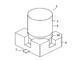
- FIG. 2 is a perspective view of the electrolytic capacitor according to the first embodiment of the present invention as viewed from above.
- FIG. 2 is a perspective view of the electrolytic capacitor according to the first embodiment of the present invention as viewed from below.
- 1 is a perspective view showing a capacitor element of an electrolytic capacitor according to a first embodiment of the present invention.
- the electrolytic capacitor 1 includes a capacitor body 2 and a seat plate 6.
- the seat plate 6 is formed of a synthetic resin and holds the capacitor body 2.
- the seat plate 6 is provided with a pair of through holes 6a and 6b. Lead terminals 7 and 8 provided on a capacitor body 2 described later are bent by being inserted into through holes 6a and 6b and soldered to a circuit board.
- FIG. 3 is a front sectional view of the capacitor body 2.
- the capacitor main body 2 includes a main body case 3, a capacitor element 10, and a sealing body 5.
- the main body case 3 is formed of a metal such as aluminum into a cylindrical shape with a circular cross section and has an opening 3c at one end.
- the capacitor element 10 is housed in the main body case 3, and the opening 3 c is sealed by the sealing body 5.
- FIG. 4 is a perspective view of the capacitor element 10.
- the capacitor element 10 has an anode foil 11, a cathode foil 12, and a separator 13.
- the anode foil 11 and the cathode foil 12 are each formed in a long strip shape by a metal foil.
- the separator 13 is formed in a long band shape using a nonwoven fabric or the like.
- the capacitor element 10 is formed by winding an anode foil 11 and a cathode foil 12 in a cylindrical shape with a separator 13 interposed therebetween.
- the end of the anode foil 11 or the cathode foil 12 is fixed by a wrapping tape 14.
- the lead terminal 7 is connected to the anode foil 11, and the lead terminal 8 is connected to the cathode foil 12.
- the width in the short direction (axial direction) of the separator 13 is formed larger than the width in the short direction of the anode foil 11 and the cathode foil 12.
- the separator 13 projects upward (opposite to the opening 3c) and downward (toward the opening 3c) with respect to the anode foil 11 and the cathode foil 12, thereby preventing a short circuit between the anode foil 11 and the cathode foil 12.
- the anode foil 11 is made of a valve metal such as aluminum, tantalum, niobium, and titanium.
- the cathode foil 12 faces the anode foil 11 via the separator 13 and is formed of aluminum or the like.
- An oxide film (not shown) is formed on the surfaces of the anode foil 11 and the cathode foil 12.
- An electrolytic solution is held between the anode foil 11 and the cathode foil 12 of the capacitor element 10.
- the electrolyte permeates the separator 13 and is held between the anode foil 11 and the cathode foil 12.
- the electrolyte functions substantially as a cathode. Further, defects of the oxide films of the anode foil 11 and the cathode foil 12 can be repaired by the electrolytic solution.
- Electrolyte solution consists of solution of electrolyte in lipophilic solvent.
- Gamma-butyrolactone can be used as the lipophilic solvent.
- a liquid containing a nonionic surfactant in at least one of sulfolane, ethylene glycol, and diethylene glycol can be used.
- the nonionic surfactant polyethylene glycol or polyglycerin having a lipophilic group bonded thereto, a polyethylene glycol-polypropylene glycol copolymer, or the like can be used.
- the electrolyte dissociates into ions when dissolved in a solvent to exhibit electrical conductivity, and an organic amine salt of a boric acid compound or a carboxylic acid compound is used.
- the electrolyte solution contains a fat-soluble antioxidant dissolved in a lipophilic solvent.
- the fat-soluble antioxidant causes an oxidation reaction with oxygen, and suppresses the oxidation of the sealing body 5 as described in detail later.
- an antioxidant soluble in a lipophilic solvent is used, and for example, a fat-soluble vitamin can be used.
- fat-soluble vitamins vitamin A (retinol, ⁇ -carotene, ⁇ -carotene, ⁇ -cryptoxanthin), vitamin D (vitamin D2, vitamin D3), vitamin E (tocopherol, tocotrienol), vitamin K (vitamin K1, vitamin K2) And menaquinone 7).
- the concentration of the fat-soluble antioxidant in the electrolyte is less than 1% by weight, the effect of suppressing the oxidation of the sealing body 5 cannot be continued for a long time. If the concentration of the fat-soluble antioxidant in the electrolytic solution exceeds 30% by weight, the viscosity of the electrolytic solution increases, so that the time for which the capacitor element 10 holds the electrolytic solution is long, and the number of steps is increased. For this reason, it is desirable that the concentration of the fat-soluble antioxidant in the electrolyte be 1% by weight to 30% by weight. Further, it is more preferable that the concentration of the fat-soluble antioxidant in the electrolytic solution be 3% by weight to 20% by weight, because the effect of suppressing oxidation can be more exerted and the number of steps can be reduced.
- the sealing body 5 is formed in a disc shape having a pair of through holes 5a and 5b by a molded product of an elastic material such as rubber or the like.
- the lead terminals 7 and 8 of the capacitor element 10 are inserted into the through holes 5a and 5b by press fitting.
- the sealing member 5 butyl rubber having high environmental resistance such as heat aging resistance, chemical resistance, light resistance and the like, and high electric insulation properties and low gas permeability can be used. Further, the sealing body 5 may contain an antioxidant for suppressing deterioration.
- the sealing body 5 arranged in the opening 3 c of the main body case 3 With the sealing body 5 arranged in the opening 3 c of the main body case 3, the opening end of the main body case 3 is folded over the sealing body 5. Further, the main body case 3 is subjected to a drawing process for pressing the outer peripheral surface, and a projecting portion 3 d protruding toward the inner surface side of the main body case 3 is formed. Thereby, the sealing element 5 is fixed together with the capacitor element 10 to prevent the sealing element 5 from falling off, and the opening 3 c of the main body case 3 is sealed by the sealing element 5.
- the apex of the protruding portion 3d is arranged on a side farther from the capacitor element 10 than the center of the sealing body 5 in the thickness direction.
- the outer peripheral surface of the sealing body 5 is pressed from below in the figure, and the upper surface (the capacitor element 10 side) of the sealing body 5 curves upward and the central portion protrudes toward the capacitor element 10 side.
- FIG. 5 is a detailed view of a portion H in FIG. At least a part of the separator 13 protruding below the anode foil 11 and the cathode foil 12 contacts the sealing body 5. At this time, since the central portion of the sealing body 5 is curved so as to protrude upward, the separator 13 surely contacts the sealing body 5 at a plurality of points or surfaces along the sealing body 5.
- a fat-soluble antioxidant of the electrolytic solution is continuously supplied to the sealing body 5 through the separator 13 which comes into contact with the sealing body 5.
- the fat-soluble antioxidant reaches the inside of the sealing body 5 and the outer surface of the sealing body 5 (the surface on the opposite side of the capacitor element 10) through the intermolecular gap inside the sealing body 5. Therefore, the outer surface of the sealing body 5 is covered with the fat-soluble antioxidant in an oil film state.
- fat-soluble antioxidants have a high boiling point and a low melting point (for example, tocopherol has a boiling point of 235 ° C. and a melting point of 3 ° C.). Therefore, evaporation of the fat-soluble antioxidant covering the surface of the sealing body 5 is suppressed. This allows the fat-soluble antioxidant to remain in a liquid state between 25 ° C. and 150 ° C. around room temperature, and to form a stable oil film state.
- the contact between the sealing body 5 and oxygen in the air is suppressed, and the fat-soluble antioxidant reacts with the surface or inside of the sealing body 5 by oxidation reaction with oxygen. Therefore, the deterioration of the sealing body 5 due to oxidation can be suppressed for a long time. For this reason, it is possible to prevent the electrolytic solution from evaporating through cracks or the like of the sealing body 5.
- FIG. 6 is a diagram showing a change in capacitance due to a durability test of the electrolytic capacitor 1 of the present embodiment.
- the vertical axis indicates the rate of change of capacitance (unit:%), and the horizontal axis indicates elapsed time.
- A denotes the electrolytic capacitor 1 of the present embodiment, in which gamma-butyrolactone is used as a lipophilic solvent for an electrolytic solution and tocopherol is used as a fat-soluble antioxidant.
- the concentration of the fat-soluble antioxidant in the electrolyte is 10% by weight.
- the sealing body 5 is formed of butyl rubber, and an anti-aging agent is added.
- B indicates the electrolytic capacitor of the comparative example, and the fat-soluble antioxidant is omitted from the electrolytic solution of the electrolytic capacitor 1 shown in A.
- FIG. 7 shows an image of the sealing body 5 of the electrolytic capacitor 1 shown in FIG.
- FIG. 8 shows a photographed image of the sealing body 5 of the electrolytic capacitor shown in FIG.
- the electrolytic capacitor 1 of the present embodiment had a luster in which the surface of the sealing body 5 was covered with a fat-soluble antioxidant in an oil film state after 1500 hours and 8000 hours. . That is, tocopherol evaporates slower than gamma-butyrolactone on the surface of the sealing body 5 and can stably maintain the oil film state of the fat-soluble antioxidant even in a high temperature range of 150 ° C. where the oxidative deterioration of the sealing body 5 is fast. I was
- the change rate of the capacitance is less than 20% after 8000 hours. Therefore, stable characteristics can be exhibited for a long time even in a high temperature environment. At this time, the ESR was also kept low, and there was no adverse effect of the fat-soluble antioxidant on the electrolyte in the electrolytic solution.
- the capacitor element 10 holds the electrolyte in which the lipophilic antioxidant is dissolved in the lipophilic solvent, and the separator 13 contacts the sealing body 5.
- the fat-soluble antioxidant in the electrolytic solution is continuously supplied to the sealing body 5 through the separator 13, and the deterioration of the sealing body 5 can be suppressed for a long time. Therefore, evaporation of the electrolytic solution held in the capacitor element 10 can be prevented, and the characteristics of the electrolytic capacitor 1 can be stably maintained for a long time.
- the concentration of the fat-soluble antioxidant in the electrolytic solution is 1% by weight to 30% by weight, an increase in man-hours can be suppressed, and the effect of suppressing the oxidation of the sealing body 5 can be continued for a long time.
- the concentration of the fat-soluble antioxidant in the electrolyte is 3% by weight to 20% by weight, the effect of suppressing oxidation can be further lengthened and the number of steps can be reduced.
- the lipophilic solvent of the electrolyte can be easily realized by gamma-butyrolactone.
- the lipophilic solvent of the electrolyte can be easily realized by a liquid containing at least one of sulfolane, ethylene glycol, and diethylene glycol and a nonionic surfactant.
- nonionic surfactant can be easily realized by a liquid in which a lipophilic group is bonded to polyethylene glycol or polyglycerin.
- the nonionic surfactant can be easily realized by a polyethylene glycol-polypropylene glycol copolymer.
- the fat-soluble antioxidant of the electrolytic solution can be easily realized by the fat-soluble vitamin.
- fat-soluble vitamins that dissolve in the lipophilic solvent of the electrolyte can be easily realized with tocopherol or tocotrienol.
- the separator 13 protrudes toward the sealing body 5 from the anode foil 11 and the cathode foil 12, the separator 13 can be easily brought into contact with the sealing body 5.
- the apex of the protruding portion 3 d protruding on the inner surface of the main body case 3 is arranged on a side farther from the capacitor element 10 than the center in the thickness direction of the sealing body 5.
- the central portion of the sealing body 5 projects toward the capacitor element 10, and the separator 13 reliably contacts the sealing body 5 at a plurality of points or surfaces along the sealing body 5.
- the capacitor element 10 holds a solid electrolyte (not shown) and a predetermined functional liquid instead of the electrolytic solution.
- Other parts are the same as in the first embodiment.
- the solid electrolyte is made of a conductive polymer or the like.
- the ESR of the electrolytic capacitor 1 can be reduced by the conductive polymer.
- the conductive polymer polythiophene, polypyrrole, a derivative thereof, or the like can be used, and polyethylene dioxythiophene is more preferable because of its high electrical conductivity.
- the solid electrolyte made of the conductive polymer can be held between the anode foil 11 and the cathode foil 12.
- a functional liquid having a function of increasing the withstand voltage is held between the anode foil 11 and the cathode foil 12.
- the functional liquid consists of a solution of a fat-soluble antioxidant in a lipophilic solvent.
- Gamma-butyrolactone can be used as the lipophilic solvent.
- a liquid containing a nonionic surfactant in at least one of sulfolane, ethylene glycol, and diethylene glycol can be used as the nonionic surfactant.
- polyethylene glycol or polyglycerin having a lipophilic group bonded thereto, a polyethylene glycol-polypropylene glycol copolymer, or the like can be used. With these lipophilic solvents, the withstand voltage can be increased and the fat-soluble antioxidant can be dissolved.
- the fat-soluble antioxidant an antioxidant soluble in a lipophilic solvent is used, and for example, a fat-soluble vitamin can be used.
- a fat-soluble vitamin can be used.
- vitamin A retinol, ⁇ -carotene, ⁇ -carotene, ⁇ -cryptoxanthin
- vitamin D vitamin D2, vitamin D3
- vitamin E tocopherol, tocotrienol
- vitamin K vitamin K1, vitamin K2
- menaquinone 7 menaquinone 7
- the functional liquid Since the solid electrolyte is swollen by the functional liquid, the degree of adhesion of the solid electrolyte to the anode foil 11 and the cathode foil 12 sandwiching the solid electrolyte increases. Thereby, the ESR of the electrolytic capacitor 1 can be reduced. Therefore, the functional liquid also has a function of reducing the ESR of the electrolytic capacitor 1.
- the separator 13 of the capacitor element 10 is in contact with the sealing body 5, and the fat-soluble antioxidant of the functional liquid is supplied to the sealing body 5 via the separator 13.
- the fat-soluble antioxidant reaches the inside of the sealing body 5 and the outer surface of the sealing body 5 (the surface on the opposite side of the capacitor element 10) through the intermolecular gap inside the sealing body 5. Therefore, the outer surface of the sealing body 5 is covered with the fat-soluble antioxidant in an oil film state.
- the contact between the sealing body 5 and oxygen in the air is suppressed, and the fat-soluble antioxidant reacts with the surface or inside of the sealing body 5 by oxidation reaction with oxygen. Therefore, the deterioration of the sealing body 5 due to oxidation can be suppressed, and the functional liquid can be prevented from falling out.
- the capacitor element 10 holds the functional liquid and the solid electrolyte in which the lipophilic antioxidant is dissolved in the lipophilic solvent, and the separator 13 contacts the sealing body 5.
- the fat-soluble antioxidant in the functional liquid is continuously supplied to the sealing body 5 via the separator 13, and the deterioration of the sealing body 5 can be suppressed for a long time. Therefore, it is possible to prevent the functional liquid held by the capacitor element 10 from leaking out, and to stably maintain the characteristics of the electrolytic capacitor 1 for a long period of time.
- an electrolytic solution obtained by dissolving an electrolyte in the functional liquid may be held between the anode foil 11 and the cathode foil 12.
- the function of repairing the oxide film can be enhanced, and the ESR of the electrolytic capacitor 1 can be further reduced.
- the present invention can be used for an electrolytic capacitor and an automobile, an electronic device, and the like in which the electrolytic capacitor is mounted on a control circuit.
- Electrolytic capacitor 1
- Capacitor main body 3
- Main body case 3c Opening 3d Projecting part 5
- Sealing body 5a, 5b Through hole 6
- Seat plate 6a, 6b Through hole 7 8
- Lead terminal 10
- Capacitor element 11
- Anode foil 12
Abstract
An electrolytic capacitor 1 comprises: a capacitor element 10 in which a cathode foil 11 and an anode foil 12 are wound, with a separator 13 sandwiched therebetween, and a prescribed solution is held between the cathode foil 11 and the anode foil 12; a body case 3 housing the capacitor element 10; and a sealing body 5 which seals the body case 3. The solution is a fat-soluble antioxidant dissolved in a lypophilic solvent and the separator 13 is configured to be in contact with the sealing body 5.
Description
本発明は、封口体により封止される電解コンデンサに関する。
The present invention relates to an electrolytic capacitor sealed by a sealing body.
従来の電解コンデンサは特許文献1に開示されている。この電解コンデンサは本体ケース、コンデンサ素子及び封口体を備えている。本体ケースは金属によって有底筒状に形成され、円筒状の周壁の一端を閉塞して他端に開口部を開口する。
A conventional electrolytic capacitor is disclosed in Patent Document 1. This electrolytic capacitor includes a main body case, a capacitor element, and a sealing body. The main body case is formed in a cylindrical shape with a bottom with metal, and has a cylindrical peripheral wall closed at one end and an opening at the other end.
コンデンサ素子は酸化皮膜が形成された陽極箔と陰極箔とをセパレータを介して巻回され、本体ケースに収納される。陽極箔と陰極箔との間には電解液が保持される。また、陽極箔及び陰極箔にはそれぞれリード端子が接続される。コンデンサ素子を収納した本体ケースの開口部はゴム等の封口体により封口され、リード端子は封口体を貫通して本体ケース外に引き出される。
The capacitor element is wound around a separator with an anode foil and a cathode foil on which an oxide film is formed, and is housed in a main body case. An electrolytic solution is held between the anode foil and the cathode foil. Lead terminals are connected to the anode foil and the cathode foil, respectively. The opening of the main body case containing the capacitor element is sealed by a sealing body such as rubber, and the lead terminals are drawn out of the main body case through the sealing body.
ゴム等の高分子は空気中等の酸素存在下で熱や光のエネルギーを受けると、ラジカルの生成をきっかけとして連鎖的な酸化反応が起こり、物性低下を生ずると言われている。このため、封口体に酸化反応を抑制するための老化防止剤を混入することが述べられる。
高分子 When a polymer such as rubber receives heat or light energy in the presence of oxygen in the air or the like, it is said that the generation of radicals triggers a chain oxidation reaction, which causes a deterioration in physical properties. For this reason, it is stated that an antioxidant for suppressing an oxidation reaction is mixed into the sealing body.
また、特許文献2には電解液に替えて固体電解質を有する電解コンデンサが開示される。この電解コンデンサは特許文献1と同様の本体ケース、コンデンサ素子及び封口体を備えている。コンデンサ素子の陽極箔と陰極箔との間には固体電解質である導電性高分子が保持される。また、陽極箔と陰極箔との間には水分を含有する親水性高分子化合物が保持される。
特許 Patent Document 2 discloses an electrolytic capacitor having a solid electrolyte instead of an electrolytic solution. This electrolytic capacitor includes a main body case, a capacitor element, and a sealing body similar to those in Patent Document 1. A conductive polymer, which is a solid electrolyte, is held between the anode foil and the cathode foil of the capacitor element. Further, a hydrophilic polymer compound containing water is held between the anode foil and the cathode foil.
上記構成の電解コンデンサによると、導電性高分子によりESRを低くすることができる。また、親水性高分子化合物に含有される水分によって陽極箔及び陰極箔の酸化皮膜の欠陥を修復することができる。
According to the electrolytic capacitor having the above configuration, the ESR can be reduced by the conductive polymer. In addition, the defects contained in the oxide films of the anode foil and the cathode foil can be repaired by the moisture contained in the hydrophilic polymer compound.
近年、電解コンデンサは搭載される機器の小型化及び高性能化により、大きな発熱を伴うモータ、エンジン、高速処理用半導体素子等の近傍に配置される高温環境下での使用が多くなってきている。
In recent years, electrolytic capacitors have been increasingly used in high-temperature environments arranged near motors, engines, high-speed processing semiconductor elements, and the like that generate large heat due to miniaturization and high performance of mounted devices. .
上記特許文献1に開示される電解コンデンサによると、封口体に混入された老化防止剤は酸化防止作用を果たすにつれて消費され、次第に失われる。電解コンデンサを高温環境下で使用すると封口体は老化防止剤の消失に伴って急速に劣化する。このため、電解液が本体ケース外へ蒸散し、最終的にドライアップと言われる状態になることが多い。従って、電解コンデンサの特性を長期的に安定して維持できない問題があった。
According to the electrolytic capacitor disclosed in Patent Literature 1, the antioxidant mixed in the sealing body is consumed as the antioxidant effect is achieved, and is gradually lost. When the electrolytic capacitor is used in a high temperature environment, the sealing body rapidly deteriorates with the disappearance of the antioxidant. For this reason, the electrolyte often evaporates out of the main body case, and eventually becomes a state called dry-up. Therefore, there has been a problem that the characteristics of the electrolytic capacitor cannot be stably maintained for a long period of time.
また、上記特許文献2に開示される電解コンデンサも同様に、電解コンデンサを高温環境下で使用すると封口体が劣化する。このため、陽極箔と陰極箔との間に保持される水分が本体ケース外へ抜け出て、酸化皮膜の修復を行うことができない。従って、電解コンデンサの特性を長期的に安定して維持できない問題があった。
も Similarly, the sealing body of the electrolytic capacitor disclosed in Patent Document 2 is deteriorated when the electrolytic capacitor is used in a high temperature environment. For this reason, moisture retained between the anode foil and the cathode foil leaks out of the main body case, and the oxide film cannot be repaired. Therefore, there has been a problem that the characteristics of the electrolytic capacitor cannot be stably maintained for a long period of time.
酸化皮膜の修復をするための水分に限られず、電解コンデンサの特性を高める機能を有した機能性液体をコンデンサ素子が保持する場合も同様に、高温環境下で封口体の劣化により機能性液体が抜け出る。これにより、電解コンデンサの特性を長期的に安定して維持できない問題がある。
Similarly, when the capacitor element retains a functional liquid that has the function of improving the characteristics of the electrolytic capacitor, not only water for repairing the oxide film, but also the functional liquid due to the deterioration of the sealing body in a high-temperature environment Get out. As a result, there is a problem that the characteristics of the electrolytic capacitor cannot be stably maintained for a long time.
本発明は、長期的に安定して特性を維持できる電解コンデンサを提供することを目的とする。
は An object of the present invention is to provide an electrolytic capacitor capable of maintaining its characteristics stably for a long period of time.
上記目的を達成するために本発明は、セパレータを介して陽極箔と陰極箔とを巻回して前記陽極箔と前記陰極箔との間に所定の溶液を保持したコンデンサ素子と、前記コンデンサ素子を収納する本体ケースと、前記本体ケースを封止する封口体とを備えた電解コンデンサにおいて、前記溶液が親油性溶媒に脂溶性酸化防止剤を溶解されており、前記セパレータが前記封口体に接触することを特徴としている。
In order to achieve the above object, the present invention provides a capacitor element in which a predetermined solution is held between the anode foil and the cathode foil by winding an anode foil and a cathode foil via a separator, and the capacitor element In an electrolytic capacitor including a main body case to be stored and a sealing body for sealing the main body case, the solution has a lipophilic antioxidant dissolved in a lipophilic solvent, and the separator contacts the sealing body. It is characterized by:
また本発明は、上記構成の電解コンデンサにおいて、前記コンデンサ素子が固体電解質を保持することを特徴としている。
According to the present invention, in the electrolytic capacitor having the above-described configuration, the capacitor element holds a solid electrolyte.
また本発明は、上記構成の電解コンデンサにおいて、前記溶液が前記親油性溶媒に前記脂溶性酸化防止剤及び電解質を溶解した電解液から成ることを特徴としている。
The present invention is also characterized in that in the electrolytic capacitor having the above-mentioned structure, the solution comprises an electrolytic solution obtained by dissolving the lipophilic antioxidant and an electrolyte in the lipophilic solvent.
また本発明は、上記構成の電解コンデンサにおいて、前記電解液の前記脂溶性酸化防止剤の濃度が1重量%~30重量%であることを特徴としている。
The present invention is also characterized in that in the electrolytic capacitor having the above-mentioned structure, the concentration of the fat-soluble antioxidant in the electrolytic solution is 1% by weight to 30% by weight.
また本発明は、上記構成の電解コンデンサにおいて、前記電解液の前記脂溶性酸化防止剤の濃度が3重量%~20重量%であることを特徴としている。
According to the present invention, in the electrolytic capacitor having the above structure, the concentration of the fat-soluble antioxidant in the electrolytic solution is 3% by weight to 20% by weight.
また本発明は、上記構成の電解コンデンサにおいて、前記親油性溶媒がガンマブチロラクトンであることを特徴としている。
The present invention is also characterized in that the lipophilic solvent is gamma-butyrolactone in the electrolytic capacitor having the above configuration.
また本発明は、上記構成の電解コンデンサにおいて、前記親油性溶媒が、スルホラン、エチレングリコール、ジエチレングリコールの少なくとも一つと、非イオン性界面活性剤とを含むことを特徴としている。
The present invention is also characterized in that in the electrolytic capacitor having the above configuration, the lipophilic solvent contains at least one of sulfolane, ethylene glycol, and diethylene glycol, and a nonionic surfactant.
また本発明は、上記構成の電解コンデンサにおいて、前記非イオン性界面活性剤がポリエチレングリコールまたはポリグリセリンに親油基を結合させたものであることを特徴としている。
The present invention is also characterized in that, in the electrolytic capacitor having the above-mentioned configuration, the nonionic surfactant is obtained by binding a lipophilic group to polyethylene glycol or polyglycerin.
また本発明は、上記構成の電解コンデンサにおいて、前記非イオン性界面活性剤がポリエチレングリコール-ポリプロピレングリコール共重合体であることを特徴としている。
The present invention is also characterized in that, in the electrolytic capacitor having the above-mentioned configuration, the nonionic surfactant is a polyethylene glycol-polypropylene glycol copolymer.
また本発明は、上記構成の電解コンデンサにおいて、前記脂溶性酸化防止剤が脂溶性ビタミンであることを特徴としている。
The present invention is also characterized in that the fat-soluble antioxidant is a fat-soluble vitamin in the electrolytic capacitor having the above configuration.
また本発明は、上記構成の電解コンデンサにおいて、前記脂溶性ビタミンがトコフェロールまたはトコトリエノールであることを特徴としている。
The present invention is also characterized in that in the electrolytic capacitor having the above-mentioned configuration, the fat-soluble vitamin is tocopherol or tocotrienol.
また本発明は、上記構成の電解コンデンサにおいて、前記セパレータの短手方向の幅が前記陽極箔及び前記陰極箔の短手方向の幅よりも大きく、前記セパレータが前記陽極箔及び前記陰極箔よりも前記封口体側に突出して前記封口体に接触することを特徴としている。
Further, according to the present invention, in the electrolytic capacitor having the above configuration, the width in the short direction of the separator is larger than the width in the short direction of the anode foil and the cathode foil, and the separator is larger than the anode foil and the cathode foil. It is characterized in that it protrudes toward the sealing body and comes into contact with the sealing body.
また本発明は、上記構成の電解コンデンサにおいて、前記本体ケースが内面上に突出して前記封口体の外周面を押圧する突出部を有し、前記突出部の頂点が前記封口体の厚み方向の中心よりも前記コンデンサ素子から離れた側に配されることを特徴としている。
Further, according to the present invention, in the electrolytic capacitor having the above-described configuration, the main body case has a protruding portion that protrudes on an inner surface and presses an outer peripheral surface of the sealing body, and a vertex of the protruding portion is a center in a thickness direction of the sealing body. It is characterized by being arranged on a side farther from the capacitor element than the capacitor element.
本発明によると、コンデンサ素子が親油性溶媒に脂溶性酸化防止剤を溶解した溶液を保持し、セパレータが封口体に接触するので、セパレータにより脂溶性酸化防止剤が継続的に封口体に供給される。封口体に供給された脂溶性酸化防止剤は封口体内部の分子間隙間を介して封口体の内部及び封口体の外面に到達する。これにより、封口体の表面を脂溶性酸化防止剤が油膜状に覆い、封口体の劣化を長期的に抑制することができる。このため、コンデンサ素子に保持される溶液が抜け出ることを防止し、電解コンデンサの特性を長期的に安定して維持することができる。
According to the present invention, since the capacitor element holds the solution in which the lipophilic antioxidant is dissolved in the lipophilic solvent, and the separator comes into contact with the sealing body, the lipophilic antioxidant is continuously supplied to the sealing body by the separator. You. The fat-soluble antioxidant supplied to the sealing body reaches the inside of the sealing body and the outer surface of the sealing body through the intermolecular gap inside the sealing body. Thereby, the fat-soluble antioxidant covers the surface of the sealing body in the form of an oil film, and the deterioration of the sealing body can be suppressed for a long time. Therefore, it is possible to prevent the solution held in the capacitor element from leaking out, and to stably maintain the characteristics of the electrolytic capacitor for a long period of time.
<第1実施形態>
以下に図面を参照して本発明の実施形態を説明する。図1及び図2は第1実施形態の電解コンデンサ1を上方から見た斜視図及び下方から見た斜視図を示している。電解コンデンサ1はコンデンサ本体2と座板6とを備えている。座板6は合成樹脂により形成され、コンデンサ本体2を保持する。座板6には一対の貫通孔6a、6bが設けられる。後述するコンデンサ本体2に設けられたリード端子7、8は貫通孔6a、6bに挿通して折曲され、回路基板に半田付けされる。 <First embodiment>
An embodiment of the present invention will be described below with reference to the drawings. 1 and 2 show a perspective view of theelectrolytic capacitor 1 of the first embodiment as viewed from above and a perspective view as viewed from below. The electrolytic capacitor 1 includes a capacitor body 2 and a seat plate 6. The seat plate 6 is formed of a synthetic resin and holds the capacitor body 2. The seat plate 6 is provided with a pair of through holes 6a and 6b. Lead terminals 7 and 8 provided on a capacitor body 2 described later are bent by being inserted into through holes 6a and 6b and soldered to a circuit board.
以下に図面を参照して本発明の実施形態を説明する。図1及び図2は第1実施形態の電解コンデンサ1を上方から見た斜視図及び下方から見た斜視図を示している。電解コンデンサ1はコンデンサ本体2と座板6とを備えている。座板6は合成樹脂により形成され、コンデンサ本体2を保持する。座板6には一対の貫通孔6a、6bが設けられる。後述するコンデンサ本体2に設けられたリード端子7、8は貫通孔6a、6bに挿通して折曲され、回路基板に半田付けされる。 <First embodiment>
An embodiment of the present invention will be described below with reference to the drawings. 1 and 2 show a perspective view of the
図3はコンデンサ本体2の正面断面図を示している。コンデンサ本体2は本体ケース3、コンデンサ素子10及び封口体5を備えている。本体ケース3はアルミニウム等の金属により断面円形の有底筒状に形成され、一端に開口部3cを開口する。本体ケース3内にコンデンサ素子10が収納され、開口部3cが封口体5により封止される。
FIG. 3 is a front sectional view of the capacitor body 2. The capacitor main body 2 includes a main body case 3, a capacitor element 10, and a sealing body 5. The main body case 3 is formed of a metal such as aluminum into a cylindrical shape with a circular cross section and has an opening 3c at one end. The capacitor element 10 is housed in the main body case 3, and the opening 3 c is sealed by the sealing body 5.
図4はコンデンサ素子10の斜視図を示している。コンデンサ素子10は陽極箔11、陰極箔12及びセパレータ13を有している。陽極箔11及び陰極箔12は金属箔によりそれぞれ長尺の帯状に形成される。セパレータ13は不織布等により長尺の帯状に形成される。
FIG. 4 is a perspective view of the capacitor element 10. The capacitor element 10 has an anode foil 11, a cathode foil 12, and a separator 13. The anode foil 11 and the cathode foil 12 are each formed in a long strip shape by a metal foil. The separator 13 is formed in a long band shape using a nonwoven fabric or the like.
コンデンサ素子10は陽極箔11と陰極箔12とをセパレータ13を介して円筒状に巻回して形成される。陽極箔11または陰極箔12の終端は巻止めテープ14によって固定される。陽極箔11にはリード端子7が接続され、陰極箔12にはリード端子8が接続される。
The capacitor element 10 is formed by winding an anode foil 11 and a cathode foil 12 in a cylindrical shape with a separator 13 interposed therebetween. The end of the anode foil 11 or the cathode foil 12 is fixed by a wrapping tape 14. The lead terminal 7 is connected to the anode foil 11, and the lead terminal 8 is connected to the cathode foil 12.
セパレータ13の短手方向(軸方向)の幅は陽極箔11及び陰極箔12の短手方向の幅よりも大きく形成される。これにより、セパレータ13は陽極箔11及び陰極箔12に対して上方(開口部3cの反対側)及び下方(開口部3c側)に突出し、陽極箔11と陰極箔12との短絡が防止される。
(4) The width in the short direction (axial direction) of the separator 13 is formed larger than the width in the short direction of the anode foil 11 and the cathode foil 12. Thus, the separator 13 projects upward (opposite to the opening 3c) and downward (toward the opening 3c) with respect to the anode foil 11 and the cathode foil 12, thereby preventing a short circuit between the anode foil 11 and the cathode foil 12. .
陽極箔11はアルミニウム、タンタル、ニオブ、チタン等の弁作用金属から成っている。陰極箔12はセパレータ13を介して陽極箔11に対向し、アルミニウム等により形成される。陽極箔11及び陰極箔12の表面には酸化皮膜(不図示)が形成される。
The anode foil 11 is made of a valve metal such as aluminum, tantalum, niobium, and titanium. The cathode foil 12 faces the anode foil 11 via the separator 13 and is formed of aluminum or the like. An oxide film (not shown) is formed on the surfaces of the anode foil 11 and the cathode foil 12.
また、コンデンサ素子10の陽極箔11と陰極箔12との間には電解液が保持される。電解液にコンデンサ素子10を所定時間浸漬することにより、電解液がセパレータ13に浸透して陽極箔11と陰極箔12との間に保持される。電解液は実質上の陰極として機能する。また、電解液によって陽極箔11及び陰極箔12の酸化皮膜の欠陥を修復することができる。
(4) An electrolytic solution is held between the anode foil 11 and the cathode foil 12 of the capacitor element 10. By immersing the capacitor element 10 in the electrolyte for a predetermined time, the electrolyte permeates the separator 13 and is held between the anode foil 11 and the cathode foil 12. The electrolyte functions substantially as a cathode. Further, defects of the oxide films of the anode foil 11 and the cathode foil 12 can be repaired by the electrolytic solution.
電解液は親油性溶媒に電解質を溶解した溶液から成っている。親油性溶媒としてガンマブチロラクトンを用いることができる。また親油性溶媒として、スルホラン、エチレングリコール、ジエチレングリコールの少なくとも一つに非イオン性界面活性剤を含む液を用いることができる。非イオン性界面活性剤として、ポリエチレングリコールまたはポリグリセリンに親油基を結合させたもの、ポリエチレングリコール-ポリプロピレングリコール共重合体等を用いることができる。
Electrolyte solution consists of solution of electrolyte in lipophilic solvent. Gamma-butyrolactone can be used as the lipophilic solvent. Further, as the lipophilic solvent, a liquid containing a nonionic surfactant in at least one of sulfolane, ethylene glycol, and diethylene glycol can be used. As the nonionic surfactant, polyethylene glycol or polyglycerin having a lipophilic group bonded thereto, a polyethylene glycol-polypropylene glycol copolymer, or the like can be used.
電解質は溶媒に溶解することによってイオンに解離して電気伝導性を発揮し、ホウ酸化合物またはカルボン酸化合物の有機アミン塩等が用いられる。
(4) The electrolyte dissociates into ions when dissolved in a solvent to exhibit electrical conductivity, and an organic amine salt of a boric acid compound or a carboxylic acid compound is used.
また、電解液には親油性溶媒に溶解した脂溶性酸化防止剤が含まれる。脂溶性酸化防止剤は酸素と酸化反応を起こし、詳細を後述するように封口体5の酸化を抑制する。脂溶性酸化防止剤として親油性溶媒に溶解する酸化防止剤が用いられ、例えば脂溶性ビタミンを用いることができる。脂溶性ビタミンとして、ビタミンA(レチノール、α-カロテン、β-カロテン、β-クリプトキサンチン)、ビタミンD(ビタミンD2、ビタミンD3)、ビタミンE(トコフェロール、トコトリエノール)、ビタミンK(ビタミンK1、ビタミンK2、メナキノン7)等が挙げられる。
電解 Furthermore, the electrolyte solution contains a fat-soluble antioxidant dissolved in a lipophilic solvent. The fat-soluble antioxidant causes an oxidation reaction with oxygen, and suppresses the oxidation of the sealing body 5 as described in detail later. As the fat-soluble antioxidant, an antioxidant soluble in a lipophilic solvent is used, and for example, a fat-soluble vitamin can be used. As fat-soluble vitamins, vitamin A (retinol, α-carotene, β-carotene, β-cryptoxanthin), vitamin D (vitamin D2, vitamin D3), vitamin E (tocopherol, tocotrienol), vitamin K (vitamin K1, vitamin K2) And menaquinone 7).
電解液中の脂溶性酸化防止剤の濃度が1重量%よりも少ないと、封口体5に対する酸化抑制効果を長期的に継続できない。電解液中の脂溶性酸化防止剤の濃度が30重量%を超えると、電解液の粘度が高くなるためコンデンサ素子10に電解液を保持させる時間が長く工数が大きくなる。このため、電解液中の脂溶性酸化防止剤の濃度を1重量%~30重量%にすると望ましい。また、電解液中の脂溶性酸化防止剤の濃度を3重量%~20重量%にすると、より酸化抑制効果を発揮して工数を削減できるためより望ましい。
(4) If the concentration of the fat-soluble antioxidant in the electrolyte is less than 1% by weight, the effect of suppressing the oxidation of the sealing body 5 cannot be continued for a long time. If the concentration of the fat-soluble antioxidant in the electrolytic solution exceeds 30% by weight, the viscosity of the electrolytic solution increases, so that the time for which the capacitor element 10 holds the electrolytic solution is long, and the number of steps is increased. For this reason, it is desirable that the concentration of the fat-soluble antioxidant in the electrolyte be 1% by weight to 30% by weight. Further, it is more preferable that the concentration of the fat-soluble antioxidant in the electrolytic solution be 3% by weight to 20% by weight, because the effect of suppressing oxidation can be more exerted and the number of steps can be reduced.
図3において、封口体5はゴム等の絶縁体の弾性材料の成形品により一対の貫通孔5a、5bを有した円板状に形成される。コンデンサ素子10のリード端子7、8は圧入によって貫通孔5a、5bに挿通される。封口体5として、耐熱老化性、耐薬品性、耐光性等の環境抵抗性や電気絶縁特性が高く、ガス透過性の低いブチルゴムを用いることができる。また、封口体5に劣化を抑制する老化防止剤を含有してもよい。
In FIG. 3, the sealing body 5 is formed in a disc shape having a pair of through holes 5a and 5b by a molded product of an elastic material such as rubber or the like. The lead terminals 7 and 8 of the capacitor element 10 are inserted into the through holes 5a and 5b by press fitting. As the sealing member 5, butyl rubber having high environmental resistance such as heat aging resistance, chemical resistance, light resistance and the like, and high electric insulation properties and low gas permeability can be used. Further, the sealing body 5 may contain an antioxidant for suppressing deterioration.
本体ケース3の開口部3cに封口体5を配した状態で、本体ケース3の開口端は封口体5上に折り返される。また、本体ケース3には外周面を押圧する絞り加工が施され、本体ケース3の内面側に突出する突出部3dが形成される。これにより、コンデンサ素子10とともに封口体5を固定して封口体5の脱落が防止され、本体ケース3の開口部3cが封口体5により封止される。
開口 With the sealing body 5 arranged in the opening 3 c of the main body case 3, the opening end of the main body case 3 is folded over the sealing body 5. Further, the main body case 3 is subjected to a drawing process for pressing the outer peripheral surface, and a projecting portion 3 d protruding toward the inner surface side of the main body case 3 is formed. Thereby, the sealing element 5 is fixed together with the capacitor element 10 to prevent the sealing element 5 from falling off, and the opening 3 c of the main body case 3 is sealed by the sealing element 5.
この時、突出部3dの頂点が封口体5の厚み方向の中心よりもコンデンサ素子10から離れた側に配される。これにより、封口体5の外周面が図中、下方から押圧され、封口体5の上面(コンデンサ素子10側)が上に凸に湾曲して中央部がコンデンサ素子10側に突出する。
At this time, the apex of the protruding portion 3d is arranged on a side farther from the capacitor element 10 than the center of the sealing body 5 in the thickness direction. As a result, the outer peripheral surface of the sealing body 5 is pressed from below in the figure, and the upper surface (the capacitor element 10 side) of the sealing body 5 curves upward and the central portion protrudes toward the capacitor element 10 side.
図5は図3のH部詳細図を示している。陽極箔11及び陰極箔12よりも下方に突出するセパレータ13の少なくとも一部は封口体5に接触する。この時、封口体5の中央部が上方に突出するように湾曲するため、セパレータ13が封口体5に沿った状態で複数点または面で確実に封口体5に当接することとなる。
FIG. 5 is a detailed view of a portion H in FIG. At least a part of the separator 13 protruding below the anode foil 11 and the cathode foil 12 contacts the sealing body 5. At this time, since the central portion of the sealing body 5 is curved so as to protrude upward, the separator 13 surely contacts the sealing body 5 at a plurality of points or surfaces along the sealing body 5.
封口体5に接触するセパレータ13を介して封口体5には継続的に電解液の脂溶性酸化防止剤が供給される。脂溶性酸化防止剤は封口体5の内部の分子間隙間を介して封口体5の内部及び封口体5の外面(コンデンサ素子10の反対側の面)に到達する。このため、封口体5の外面が脂溶性酸化防止剤によって油膜状態で覆われる。
脂 A fat-soluble antioxidant of the electrolytic solution is continuously supplied to the sealing body 5 through the separator 13 which comes into contact with the sealing body 5. The fat-soluble antioxidant reaches the inside of the sealing body 5 and the outer surface of the sealing body 5 (the surface on the opposite side of the capacitor element 10) through the intermolecular gap inside the sealing body 5. Therefore, the outer surface of the sealing body 5 is covered with the fat-soluble antioxidant in an oil film state.
また、脂溶性酸化防止剤は沸点が高く、融点が低い(例えば、トコフェロールの沸点は235℃、融点は3℃)。このため、封口体5の表面を覆う脂溶性酸化防止剤の蒸散が抑制される。これにより、室温付近の25℃から150℃の間で脂溶性酸化防止剤が液状を保ち、安定した油膜状態を形成することができる。
脂 Also, fat-soluble antioxidants have a high boiling point and a low melting point (for example, tocopherol has a boiling point of 235 ° C. and a melting point of 3 ° C.). Therefore, evaporation of the fat-soluble antioxidant covering the surface of the sealing body 5 is suppressed. This allows the fat-soluble antioxidant to remain in a liquid state between 25 ° C. and 150 ° C. around room temperature, and to form a stable oil film state.
これにより、封口体5と空気中の酸素との接触が抑制されるとともに、脂溶性酸化防止剤が封口体5の表面または内部の酸素と酸化反応する。従って、封口体5の酸化による劣化を長期的に抑制することができる。このため、封口体5のクラック等を介して電解液が蒸散されることを防止することができる。
Thereby, the contact between the sealing body 5 and oxygen in the air is suppressed, and the fat-soluble antioxidant reacts with the surface or inside of the sealing body 5 by oxidation reaction with oxygen. Therefore, the deterioration of the sealing body 5 due to oxidation can be suppressed for a long time. For this reason, it is possible to prevent the electrolytic solution from evaporating through cracks or the like of the sealing body 5.
図6は本実施形態の電解コンデンサ1の耐久試験による静電容量の変化を示す図である。同図において縦軸は静電容量の変化率(単位:%)を示し、横軸は経過時間を示している。
FIG. 6 is a diagram showing a change in capacitance due to a durability test of the electrolytic capacitor 1 of the present embodiment. In the figure, the vertical axis indicates the rate of change of capacitance (unit:%), and the horizontal axis indicates elapsed time.
図中、Aは本実施形態の電解コンデンサ1であり、電解液の親油性溶媒としてガンマブチロラクトンを用いて脂溶性酸化防止剤としてトコフェロールを用いている。電解液中の脂溶性酸化防止剤の濃度は10重量%である。また、封口体5をブチルゴムにより形成し、老化防止剤を添加している。
中 In the figure, A denotes the electrolytic capacitor 1 of the present embodiment, in which gamma-butyrolactone is used as a lipophilic solvent for an electrolytic solution and tocopherol is used as a fat-soluble antioxidant. The concentration of the fat-soluble antioxidant in the electrolyte is 10% by weight. Further, the sealing body 5 is formed of butyl rubber, and an anti-aging agent is added.
図中、Bは比較例の電解コンデンサを示しており、Aに示す電解コンデンサ1の電解液から脂溶性酸化防止剤を省いている。
BIn the figure, B indicates the electrolytic capacitor of the comparative example, and the fat-soluble antioxidant is omitted from the electrolytic solution of the electrolytic capacitor 1 shown in A.
本実施形態及び比較例の電解コンデンサ1を150℃の高温環境下で耐久試験を行い、静電容量を測定した。図7はAに示す電解コンデンサ1の8000時間経過時の封口体5の撮影画像を示している。図8はBに示す電解コンデンサの4000時間経過時の封口体5の撮影画像を示している。
(4) The electrolytic capacitors 1 of the present embodiment and the comparative example were subjected to a durability test in a high-temperature environment of 150 ° C., and the capacitance was measured. FIG. 7 shows an image of the sealing body 5 of the electrolytic capacitor 1 shown in FIG. FIG. 8 shows a photographed image of the sealing body 5 of the electrolytic capacitor shown in FIG.
耐久試験を行った結果、比較例の電解コンデンサは1500時間経過時点で封口体5の表面が老化防止剤の効果を失われて乾燥状態にあることが確認された。また、4000時間の経過時点で封口体5にクラックが発生し(図8参照)、電解液が急速に蒸散して静電容量が急速に低下した。
(4) As a result of the durability test, it was confirmed that the surface of the sealing body 5 lost the effect of the anti-aging agent and was in a dry state after the elapse of 1500 hours. After 4000 hours, cracks occurred in the sealing body 5 (see FIG. 8), and the electrolytic solution rapidly evaporated and the capacitance rapidly decreased.
これに対して、本実施形態の電解コンデンサ1は1500時間及び8000時間経過時点で封口体5の表面が脂溶性酸化防止剤により油膜状態で覆われた光沢を有していることが確認された。即ち、封口体5の表面においてトコフェロールはガンマブチロラクトンよりも蒸発が遅く、封口体5の酸化劣化が速くなる150℃の高温度域でも安定して脂溶性酸化防止剤の油膜状態を保つことができていた。
On the other hand, it was confirmed that the electrolytic capacitor 1 of the present embodiment had a luster in which the surface of the sealing body 5 was covered with a fat-soluble antioxidant in an oil film state after 1500 hours and 8000 hours. . That is, tocopherol evaporates slower than gamma-butyrolactone on the surface of the sealing body 5 and can stably maintain the oil film state of the fat-soluble antioxidant even in a high temperature range of 150 ° C. where the oxidative deterioration of the sealing body 5 is fast. I was
また、本実施形態の電解コンデンサ1は8000時間経過時点で静電容量の変化率が20%よりも小さくなっている。従って、高温環境下でも長期的に安定した特性を発揮することができる。この時、ESRも低い状態を保っており、電解液中の電解質に対して脂溶性酸化防止剤による悪影響はなかった。
{Circle around (2)} In the electrolytic capacitor 1 of this embodiment, the change rate of the capacitance is less than 20% after 8000 hours. Therefore, stable characteristics can be exhibited for a long time even in a high temperature environment. At this time, the ESR was also kept low, and there was no adverse effect of the fat-soluble antioxidant on the electrolyte in the electrolytic solution.
本実施形態によると、コンデンサ素子10が親油性溶媒に脂溶性酸化防止剤を溶解した電解液を保持し、セパレータ13が封口体5に接触する。これにより、電解液中の脂溶性酸化防止剤がセパレータ13を介して封口体5に継続的に供給され、封口体5の劣化を長期的に抑制することができる。このため、コンデンサ素子10に保持される電解液の蒸散を防止し、電解コンデンサ1の特性を長期的に安定して維持することができる。
According to the present embodiment, the capacitor element 10 holds the electrolyte in which the lipophilic antioxidant is dissolved in the lipophilic solvent, and the separator 13 contacts the sealing body 5. Thereby, the fat-soluble antioxidant in the electrolytic solution is continuously supplied to the sealing body 5 through the separator 13, and the deterioration of the sealing body 5 can be suppressed for a long time. Therefore, evaporation of the electrolytic solution held in the capacitor element 10 can be prevented, and the characteristics of the electrolytic capacitor 1 can be stably maintained for a long time.
また、電解液中の脂溶性酸化防止剤の濃度が1重量%~30重量%であるので、工数の増大を抑制し、封口体5に対する酸化抑制効果を長期的に継続することができる。
る の で Further, since the concentration of the fat-soluble antioxidant in the electrolytic solution is 1% by weight to 30% by weight, an increase in man-hours can be suppressed, and the effect of suppressing the oxidation of the sealing body 5 can be continued for a long time.
また、電解液中の脂溶性酸化防止剤の濃度が3重量%~20重量%であるので、より酸化抑制効果を長くして工数を削減できる。
る の で Further, since the concentration of the fat-soluble antioxidant in the electrolyte is 3% by weight to 20% by weight, the effect of suppressing oxidation can be further lengthened and the number of steps can be reduced.
また、電解液の親油性溶媒をガンマブチロラクトンにより容易に実現することができる。
Also, the lipophilic solvent of the electrolyte can be easily realized by gamma-butyrolactone.
また、電解液の親油性溶媒を、スルホラン、エチレングリコール、ジエチレングリコールの少なくとも一つと、非イオン性界面活性剤とを含む液により容易に実現することができる。
Also, the lipophilic solvent of the electrolyte can be easily realized by a liquid containing at least one of sulfolane, ethylene glycol, and diethylene glycol and a nonionic surfactant.
また、非イオン性界面活性剤をポリエチレングリコールまたはポリグリセリンに親油基を結合させた液により容易に実現することができる。
Also, the nonionic surfactant can be easily realized by a liquid in which a lipophilic group is bonded to polyethylene glycol or polyglycerin.
また、非イオン性界面活性剤をポリエチレングリコール-ポリプロピレングリコール共重合体により容易に実現することができる。
非 In addition, the nonionic surfactant can be easily realized by a polyethylene glycol-polypropylene glycol copolymer.
また、電解液の脂溶性酸化防止剤を脂溶性ビタミンにより容易に実現することができる。
Furthermore, the fat-soluble antioxidant of the electrolytic solution can be easily realized by the fat-soluble vitamin.
また、電解液の親油性溶媒に溶解する脂溶性ビタミンをトコフェロールまたはトコトリエノールにより容易に実現することができる。
脂 Also, fat-soluble vitamins that dissolve in the lipophilic solvent of the electrolyte can be easily realized with tocopherol or tocotrienol.
また、セパレータ13が陽極箔11及び陰極箔12よりも封口体5側に突出するので、セパレータ13を容易に封口体5に接触させることができる。
Moreover, since the separator 13 protrudes toward the sealing body 5 from the anode foil 11 and the cathode foil 12, the separator 13 can be easily brought into contact with the sealing body 5.
また、本体ケース3の内面上に突出する突出部3dの頂点が封口体5の厚み方向の中心よりもコンデンサ素子10から離れた側に配される。これにより、封口体5の中央部がコンデンサ素子10側に突出し、セパレータ13が封口体5に沿った状態で複数点または面で確実に封口体5に当接する。
(4) Further, the apex of the protruding portion 3 d protruding on the inner surface of the main body case 3 is arranged on a side farther from the capacitor element 10 than the center in the thickness direction of the sealing body 5. As a result, the central portion of the sealing body 5 projects toward the capacitor element 10, and the separator 13 reliably contacts the sealing body 5 at a plurality of points or surfaces along the sealing body 5.
<第2実施形態>
次に、第2実施形態について説明する。本実施形態はコンデンサ素子10が電解液に替えて固体電解質(不図示)及び所定の機能性液体を保持する。その他の部分は第1実施形態と同様である。 <Second embodiment>
Next, a second embodiment will be described. In the present embodiment, thecapacitor element 10 holds a solid electrolyte (not shown) and a predetermined functional liquid instead of the electrolytic solution. Other parts are the same as in the first embodiment.
次に、第2実施形態について説明する。本実施形態はコンデンサ素子10が電解液に替えて固体電解質(不図示)及び所定の機能性液体を保持する。その他の部分は第1実施形態と同様である。 <Second embodiment>
Next, a second embodiment will be described. In the present embodiment, the
固体電解質は導電性高分子等により構成される。導電性高分子によって電解コンデンサ1のESRを低くすることができる。導電性高分子として、ポリチオフェン、ポリピロールまたはこれらの誘導体等を用いることができ、ポリエチレンジオキシチオフェンは電気伝導率が高いためより望ましい。
The solid electrolyte is made of a conductive polymer or the like. The ESR of the electrolytic capacitor 1 can be reduced by the conductive polymer. As the conductive polymer, polythiophene, polypyrrole, a derivative thereof, or the like can be used, and polyethylene dioxythiophene is more preferable because of its high electrical conductivity.
導電性高分子の分散液にコンデンサ素子10を所定時間浸漬した後に乾燥することにより、導電性高分子から成る固体電解質を陽極箔11と陰極箔12との間に保持することができる。
(4) By immersing the capacitor element 10 in the conductive polymer dispersion for a predetermined time and then drying, the solid electrolyte made of the conductive polymer can be held between the anode foil 11 and the cathode foil 12.
また、陽極箔11と陰極箔12との間には耐電圧を高くする機能を有した機能性液体が保持される。機能性液体は親油性溶媒に脂溶性酸化防止剤を溶解した溶液から成っている。親油性溶媒として、ガンマブチロラクトンを用いることができる。また親油性溶媒として、スルホラン、エチレングリコール、ジエチレングリコールの少なくとも一つに非イオン性界面活性剤を含む液を用いることができる。非イオン性界面活性剤として、ポリエチレングリコールまたはポリグリセリンに親油基を結合させたもの、ポリエチレングリコール-ポリプロピレングリコール共重合体等を用いることができる。これらの親油性溶媒により耐電圧を高くすることができるとともに、脂溶性酸化防止剤を溶解させることができる。
(4) A functional liquid having a function of increasing the withstand voltage is held between the anode foil 11 and the cathode foil 12. The functional liquid consists of a solution of a fat-soluble antioxidant in a lipophilic solvent. Gamma-butyrolactone can be used as the lipophilic solvent. Further, as the lipophilic solvent, a liquid containing a nonionic surfactant in at least one of sulfolane, ethylene glycol, and diethylene glycol can be used. As the nonionic surfactant, polyethylene glycol or polyglycerin having a lipophilic group bonded thereto, a polyethylene glycol-polypropylene glycol copolymer, or the like can be used. With these lipophilic solvents, the withstand voltage can be increased and the fat-soluble antioxidant can be dissolved.
脂溶性酸化防止剤として親油性溶媒に溶解する酸化防止剤が用いられ、例えば脂溶性ビタミンを用いることができる。脂溶性ビタミンとして、ビタミンA(レチノール、α-カロテン、β-カロテン、β-クリプトキサンチン)、ビタミンD(ビタミンD2、ビタミンD3)、ビタミンE(トコフェロール、トコトリエノール)、ビタミンK(ビタミンK1、ビタミンK2、メナキノン7)等が挙げられる。
As the fat-soluble antioxidant, an antioxidant soluble in a lipophilic solvent is used, and for example, a fat-soluble vitamin can be used. As fat-soluble vitamins, vitamin A (retinol, α-carotene, β-carotene, β-cryptoxanthin), vitamin D (vitamin D2, vitamin D3), vitamin E (tocopherol, tocotrienol), vitamin K (vitamin K1, vitamin K2) And menaquinone 7).
また、固体電解質は機能性液体により膨潤状態となるため、固体電解質を挟む陽極箔11及び陰極箔12に対する固体電解質の密着度が高くなる。これにより、電解コンデンサ1のESRを低下させることができる。従って、機能性液体は電解コンデンサ1のESRを低下させる機能も有している。
(4) Since the solid electrolyte is swollen by the functional liquid, the degree of adhesion of the solid electrolyte to the anode foil 11 and the cathode foil 12 sandwiching the solid electrolyte increases. Thereby, the ESR of the electrolytic capacitor 1 can be reduced. Therefore, the functional liquid also has a function of reducing the ESR of the electrolytic capacitor 1.
第1実施形態と同様にコンデンサ素子10のセパレータ13は封口体5に接触しており、機能性液体の脂溶性酸化防止剤はセパレータ13を介して封口体5に供給される。脂溶性酸化防止剤は封口体5の内部の分子間隙間を介して封口体5の内部及び封口体5の外面(コンデンサ素子10の反対側の面)に到達する。このため、封口体5の外面が脂溶性酸化防止剤によって油膜状態で覆われる。
セ パ レ ー タ Similar to the first embodiment, the separator 13 of the capacitor element 10 is in contact with the sealing body 5, and the fat-soluble antioxidant of the functional liquid is supplied to the sealing body 5 via the separator 13. The fat-soluble antioxidant reaches the inside of the sealing body 5 and the outer surface of the sealing body 5 (the surface on the opposite side of the capacitor element 10) through the intermolecular gap inside the sealing body 5. Therefore, the outer surface of the sealing body 5 is covered with the fat-soluble antioxidant in an oil film state.
これにより、封口体5と空気中の酸素との接触が抑制されるとともに、脂溶性酸化防止剤が封口体5の表面または内部の酸素と酸化反応する。従って、封口体5の酸化による劣化を抑制することができ、機能性液体が抜け出ることを防止できる。
Thereby, the contact between the sealing body 5 and oxygen in the air is suppressed, and the fat-soluble antioxidant reacts with the surface or inside of the sealing body 5 by oxidation reaction with oxygen. Therefore, the deterioration of the sealing body 5 due to oxidation can be suppressed, and the functional liquid can be prevented from falling out.
本実施形態によると、コンデンサ素子10が親油性溶媒に脂溶性酸化防止剤を溶解した機能性液体及び固体電解質を保持し、セパレータ13が封口体5に接触する。これにより、機能性液体中の脂溶性酸化防止剤がセパレータ13を介して封口体5に継続的に供給され、封口体5の劣化を長期的に抑制することができる。このため、コンデンサ素子10に保持される機能性液体が抜け出ることを防止し、電解コンデンサ1の特性を長期的に安定して維持することができる。
According to the present embodiment, the capacitor element 10 holds the functional liquid and the solid electrolyte in which the lipophilic antioxidant is dissolved in the lipophilic solvent, and the separator 13 contacts the sealing body 5. Thereby, the fat-soluble antioxidant in the functional liquid is continuously supplied to the sealing body 5 via the separator 13, and the deterioration of the sealing body 5 can be suppressed for a long time. Therefore, it is possible to prevent the functional liquid held by the capacitor element 10 from leaking out, and to stably maintain the characteristics of the electrolytic capacitor 1 for a long period of time.
本実施形態において、上記機能性液体に電解質を溶解した電解液を陽極箔11と陰極箔12との間に保持してもよい。陽極箔11と陰極箔12との間に固体電解質及び電解液を保持することにより、酸化皮膜の修復機能を高めるとともに、電解コンデンサ1のESRをより低くすることができる。
In the present embodiment, an electrolytic solution obtained by dissolving an electrolyte in the functional liquid may be held between the anode foil 11 and the cathode foil 12. By holding the solid electrolyte and the electrolytic solution between the anode foil 11 and the cathode foil 12, the function of repairing the oxide film can be enhanced, and the ESR of the electrolytic capacitor 1 can be further reduced.
本発明は、電解コンデンサ及び電解コンデンサを制御回路に実装した自動車、電子機器等に利用することができる。
The present invention can be used for an electrolytic capacitor and an automobile, an electronic device, and the like in which the electrolytic capacitor is mounted on a control circuit.
1 電解コンデンサ
2 コンデンサ本体
3 本体ケース
3c 開口部
3d 突出部
5 封口体
5a、5b 貫通孔
6 座板
6a、6b 貫通孔
7、8 リード端子
10 コンデンサ素子
11 陽極箔
12 陰極箔
13 セパレータ
14 テープ DESCRIPTION OFSYMBOLS 1 Electrolytic capacitor 2 Capacitor main body 3 Main body case 3c Opening 3d Projecting part 5 Sealing body 5a, 5b Through hole 6 Seat plate 6a, 6b Through hole 7, 8 Lead terminal 10 Capacitor element 11 Anode foil 12 Cathode foil 13 Separator 14 Tape
2 コンデンサ本体
3 本体ケース
3c 開口部
3d 突出部
5 封口体
5a、5b 貫通孔
6 座板
6a、6b 貫通孔
7、8 リード端子
10 コンデンサ素子
11 陽極箔
12 陰極箔
13 セパレータ
14 テープ DESCRIPTION OF
Claims (13)
- セパレータを介して陽極箔と陰極箔とを巻回して前記陽極箔と前記陰極箔との間に所定の溶液を保持したコンデンサ素子と、前記コンデンサ素子を収納する本体ケースと、前記本体ケースを封止する封口体とを備えた電解コンデンサにおいて、前記溶液が親油性溶媒に脂溶性酸化防止剤を溶解されており、前記セパレータが前記封口体に接触することを特徴とする電解コンデンサ。 A capacitor element in which an anode foil and a cathode foil are wound via a separator to hold a predetermined solution between the anode foil and the cathode foil, a main body case for housing the capacitor element, and the main body case is sealed. An electrolytic capacitor provided with a sealing member for stopping the sealing, wherein the solution is obtained by dissolving a lipophilic antioxidant in a lipophilic solvent, and the separator contacts the sealing member.
- 前記コンデンサ素子が固体電解質を保持することを特徴とする請求項1に記載の電解コンデンサ。 The electrolytic capacitor according to claim 1, wherein the capacitor element holds a solid electrolyte.
- 前記溶液が前記親油性溶媒に前記脂溶性酸化防止剤及び電解質を溶解した電解液から成ることを特徴とする請求項1または請求項2に記載の電解コンデンサ。 (3) The electrolytic capacitor according to (1) or (2), wherein the solution comprises an electrolytic solution obtained by dissolving the lipophilic antioxidant and an electrolyte in the lipophilic solvent.
- 前記電解液中の前記脂溶性酸化防止剤の濃度が1重量%~30重量%であることを特徴とする請求項3に記載の電解コンデンサ。 The electrolytic capacitor according to claim 3, wherein the concentration of the fat-soluble antioxidant in the electrolyte is 1% by weight to 30% by weight.
- 前記電解液中の前記脂溶性酸化防止剤の濃度が3重量%~20重量%であることを特徴とする請求項3に記載の電解コンデンサ。 (4) The electrolytic capacitor according to (3), wherein the concentration of the fat-soluble antioxidant in the electrolytic solution is 3% by weight to 20% by weight.
- 前記親油性溶媒がガンマブチロラクトンであることを特徴とする請求項1~請求項5のいずれかに記載の電解コンデンサ。 (6) The electrolytic capacitor according to any one of (1) to (5), wherein the lipophilic solvent is gamma-butyrolactone.
- 前記親油性溶媒が、スルホラン、エチレングリコール、ジエチレングリコールの少なくとも一つと、非イオン性界面活性剤とを含むことを特徴とする請求項1~請求項5のいずれかに記載の電解コンデンサ。 (6) The electrolytic capacitor according to any one of (1) to (5), wherein the lipophilic solvent contains at least one of sulfolane, ethylene glycol, and diethylene glycol, and a nonionic surfactant.
- 前記非イオン性界面活性剤がポリエチレングリコールまたはポリグリセリンに親油基を結合させたものであることを特徴とする請求項7に記載の電解コンデンサ。 8. The electrolytic capacitor according to claim 7, wherein the nonionic surfactant is obtained by bonding a lipophilic group to polyethylene glycol or polyglycerin.
- 前記非イオン性界面活性剤がポリエチレングリコール-ポリプロピレングリコール共重合体であることを特徴とする請求項7に記載の電解コンデンサ。 8. The electrolytic capacitor according to claim 7, wherein the nonionic surfactant is a polyethylene glycol-polypropylene glycol copolymer.
- 前記脂溶性酸化防止剤が脂溶性ビタミンであることを特徴とする請求項1~請求項9のいずれかに記載の電解コンデンサ。 The electrolytic capacitor according to any one of claims 1 to 9, wherein the fat-soluble antioxidant is a fat-soluble vitamin.
- 前記脂溶性ビタミンがトコフェロールまたはトコトリエノールであることを特徴とする請求項10に記載の電解コンデンサ。 The electrolytic capacitor according to claim 10, wherein the fat-soluble vitamin is tocopherol or tocotrienol.
- 前記セパレータの短手方向の幅が前記陽極箔及び前記陰極箔の短手方向の幅よりも大きく、前記セパレータが前記陽極箔及び前記陰極箔よりも前記封口体側に突出して前記封口体に接触することを特徴とする請求項1~請求項11のいずれかに記載の電解コンデンサ。 The width in the short direction of the separator is larger than the width in the short direction of the anode foil and the cathode foil, and the separator projects toward the sealing body side from the anode foil and the cathode foil and contacts the sealing body. The electrolytic capacitor according to any one of claims 1 to 11, wherein:
- 前記本体ケースが内面上に突出して前記封口体の外周面を押圧する突出部を有し、前記突出部の頂点が前記封口体の厚み方向の中心よりも前記コンデンサ素子から離れた側に配されることを特徴とする請求項12に記載の電解コンデンサ。 The main body case has a protruding portion that protrudes on the inner surface and presses the outer peripheral surface of the sealing body, and a vertex of the protruding portion is arranged on a side farther from the capacitor element than a center in a thickness direction of the sealing body. The electrolytic capacitor according to claim 12, wherein:
Priority Applications (7)
| Application Number | Priority Date | Filing Date | Title |
|---|---|---|---|
| JP2020547554A JPWO2020059091A1 (en) | 2018-09-20 | 2018-09-20 | Electrolytic capacitor |
| US17/270,472 US11380493B2 (en) | 2018-09-20 | 2018-09-20 | Electrolytic capacitor |
| CN201880097841.5A CN112740346B (en) | 2018-09-20 | 2018-09-20 | Electrolytic capacitor |
| EP18934106.8A EP3855464A4 (en) | 2018-09-20 | 2018-09-20 | Electrolytic capacitor |
| PCT/JP2018/034885 WO2020059091A1 (en) | 2018-09-20 | 2018-09-20 | Electrolytic capacitor |
| CN202310522067.0A CN116364438A (en) | 2018-09-20 | 2018-09-20 | Electrolytic capacitor |
| JP2023001795A JP2023040185A (en) | 2018-09-20 | 2023-01-10 | Electrolytic capacitor |
Applications Claiming Priority (1)
| Application Number | Priority Date | Filing Date | Title |
|---|---|---|---|
| PCT/JP2018/034885 WO2020059091A1 (en) | 2018-09-20 | 2018-09-20 | Electrolytic capacitor |
Publications (1)
| Publication Number | Publication Date |
|---|---|
| WO2020059091A1 true WO2020059091A1 (en) | 2020-03-26 |
Family
ID=69888598
Family Applications (1)
| Application Number | Title | Priority Date | Filing Date |
|---|---|---|---|
| PCT/JP2018/034885 WO2020059091A1 (en) | 2018-09-20 | 2018-09-20 | Electrolytic capacitor |
Country Status (5)
| Country | Link |
|---|---|
| US (1) | US11380493B2 (en) |
| EP (1) | EP3855464A4 (en) |
| JP (2) | JPWO2020059091A1 (en) |
| CN (2) | CN116364438A (en) |
| WO (1) | WO2020059091A1 (en) |
Cited By (2)
| Publication number | Priority date | Publication date | Assignee | Title |
|---|---|---|---|---|
| WO2023027059A1 (en) | 2021-08-26 | 2023-03-02 | サン電子工業株式会社 | Electrolytic capacitor |
| WO2024004571A1 (en) * | 2022-06-30 | 2024-01-04 | エルナー株式会社 | Electrolytic capacitor, method for manufacturing same, and retaining member |
Families Citing this family (2)
| Publication number | Priority date | Publication date | Assignee | Title |
|---|---|---|---|---|
| JP7396695B2 (en) | 2019-09-13 | 2023-12-12 | サン電子工業株式会社 | capacitor |
| JP7465575B2 (en) * | 2020-02-28 | 2024-04-11 | サン電子工業株式会社 | Capacitor |
Citations (7)
| Publication number | Priority date | Publication date | Assignee | Title |
|---|---|---|---|---|
| JPH0538866U (en) * | 1991-10-18 | 1993-05-25 | ニチコン株式会社 | Electrolytic capacitor |
| JP2000100670A (en) | 1998-09-24 | 2000-04-07 | Matsushita Electric Ind Co Ltd | Capacitor |
| JP2005209902A (en) * | 2004-01-23 | 2005-08-04 | Sanyo Electric Co Ltd | Electrolytic capacitor |
| WO2011099261A1 (en) * | 2010-02-15 | 2011-08-18 | パナソニック株式会社 | Electrolytic capacitor |
| WO2014050913A1 (en) | 2012-09-29 | 2014-04-03 | ルビコン株式会社 | Solid electrolyte capacitor and manufacturing method for same |
| JP2014182978A (en) * | 2013-03-21 | 2014-09-29 | Mitsubishi Paper Mills Ltd | Cell separator |
| JP2018088306A (en) * | 2016-11-28 | 2018-06-07 | 富士フイルム株式会社 | Solid electrolyte composition, solid electrolyte containing sheet, all-solid type secondary battery, and manufacturing method of solid electrolyte containing sheet and all-solid type secondary battery |
Family Cites Families (14)
| Publication number | Priority date | Publication date | Assignee | Title |
|---|---|---|---|---|
| JPH01167965A (en) | 1987-12-23 | 1989-07-03 | Toray Ind Inc | Electric element |
| JP3290256B2 (en) * | 1993-06-30 | 2002-06-10 | ニチコン株式会社 | Electrolytic capacitor |
| JP3682786B2 (en) * | 1995-07-17 | 2005-08-10 | 株式会社カネカ | Electrolytic capacitor sealing body |
| TW521289B (en) * | 2001-01-17 | 2003-02-21 | Matsushita Electric Ind Co Ltd | Electronic component |
| EP1808875B1 (en) * | 2004-09-07 | 2017-11-08 | Panasonic Intellectual Property Management Co., Ltd. | Electrolyte for electrolytic capacitor and electrolytic capacitor utilizing the same |
| JP4536625B2 (en) * | 2004-09-07 | 2010-09-01 | パナソニック株式会社 | Electrolytic solution for electrolytic capacitor and electrolytic capacitor using the same |
| JP5052746B2 (en) * | 2004-10-12 | 2012-10-17 | パナソニック株式会社 | Electrolytic capacitor |
| JP4534712B2 (en) | 2004-10-21 | 2010-09-01 | パナソニック株式会社 | Electrolytic capacitor |
| JP2007080888A (en) | 2005-09-12 | 2007-03-29 | Sanyo Chem Ind Ltd | Electrolyte for electrolytic capacitor, and electrolytic capacitor using the same |
| EP2012331A4 (en) * | 2006-04-25 | 2012-05-09 | Showa Denko Kk | Electric double-layered capacitor |
| WO2016174806A1 (en) | 2015-04-28 | 2016-11-03 | パナソニックIpマネジメント株式会社 | Electrolytic capacitor |
| CN107533922B (en) * | 2015-04-28 | 2019-12-10 | 松下知识产权经营株式会社 | Electrolytic capacitor |
| WO2017094242A1 (en) | 2015-12-04 | 2017-06-08 | パナソニックIpマネジメント株式会社 | Electrolytic capacitor |
| DE102016125733A1 (en) * | 2016-12-27 | 2018-06-28 | Epcos Ag | Hybrid polymer aluminum electrolytic capacitor and method of making a capacitor |
-
2018
- 2018-09-20 US US17/270,472 patent/US11380493B2/en active Active
- 2018-09-20 CN CN202310522067.0A patent/CN116364438A/en active Pending
- 2018-09-20 CN CN201880097841.5A patent/CN112740346B/en active Active
- 2018-09-20 JP JP2020547554A patent/JPWO2020059091A1/en active Pending
- 2018-09-20 WO PCT/JP2018/034885 patent/WO2020059091A1/en unknown
- 2018-09-20 EP EP18934106.8A patent/EP3855464A4/en active Pending
-
2023
- 2023-01-10 JP JP2023001795A patent/JP2023040185A/en active Pending
Patent Citations (7)
| Publication number | Priority date | Publication date | Assignee | Title |
|---|---|---|---|---|
| JPH0538866U (en) * | 1991-10-18 | 1993-05-25 | ニチコン株式会社 | Electrolytic capacitor |
| JP2000100670A (en) | 1998-09-24 | 2000-04-07 | Matsushita Electric Ind Co Ltd | Capacitor |
| JP2005209902A (en) * | 2004-01-23 | 2005-08-04 | Sanyo Electric Co Ltd | Electrolytic capacitor |
| WO2011099261A1 (en) * | 2010-02-15 | 2011-08-18 | パナソニック株式会社 | Electrolytic capacitor |
| WO2014050913A1 (en) | 2012-09-29 | 2014-04-03 | ルビコン株式会社 | Solid electrolyte capacitor and manufacturing method for same |
| JP2014182978A (en) * | 2013-03-21 | 2014-09-29 | Mitsubishi Paper Mills Ltd | Cell separator |
| JP2018088306A (en) * | 2016-11-28 | 2018-06-07 | 富士フイルム株式会社 | Solid electrolyte composition, solid electrolyte containing sheet, all-solid type secondary battery, and manufacturing method of solid electrolyte containing sheet and all-solid type secondary battery |
Cited By (2)
| Publication number | Priority date | Publication date | Assignee | Title |
|---|---|---|---|---|
| WO2023027059A1 (en) | 2021-08-26 | 2023-03-02 | サン電子工業株式会社 | Electrolytic capacitor |
| WO2024004571A1 (en) * | 2022-06-30 | 2024-01-04 | エルナー株式会社 | Electrolytic capacitor, method for manufacturing same, and retaining member |
Also Published As
| Publication number | Publication date |
|---|---|
| US11380493B2 (en) | 2022-07-05 |
| EP3855464A1 (en) | 2021-07-28 |
| CN112740346B (en) | 2023-04-25 |
| JP2023040185A (en) | 2023-03-22 |
| CN112740346A (en) | 2021-04-30 |
| US20210327653A1 (en) | 2021-10-21 |
| EP3855464A4 (en) | 2022-04-27 |
| CN116364438A (en) | 2023-06-30 |
| JPWO2020059091A1 (en) | 2021-08-30 |
Similar Documents
| Publication | Publication Date | Title |
|---|---|---|
| WO2020059091A1 (en) | Electrolytic capacitor | |
| JP6511649B2 (en) | Method of manufacturing electrolytic capacitor and electrolytic capacitor | |
| JP7396695B2 (en) | capacitor | |
| WO2014119310A1 (en) | Electrolytic capacitor and manufacturing method thereof | |
| US9786439B2 (en) | Solid electrolyte capacitor and housing for solid electrolyte capacitor | |
| JP2007194105A (en) | Proton conductive polymer battery | |
| JP2024060049A (en) | Capacitor | |
| JP7116993B2 (en) | Electrolytic capacitor | |
| JP7465575B2 (en) | Capacitor | |
| JP3264077B2 (en) | Electrolytic capacitor | |
| JP2002083738A (en) | Lead wire for capacitor, solid electrolytic capacitor, and manufacturing method therefor | |
| JP3405003B2 (en) | Wound electrochemical element | |
| JP2001250746A (en) | Electrolytic capacitor | |
| JPWO2014068929A1 (en) | Electrolytic capacitor | |
| JPS61139019A (en) | Electrolytic capacitor | |
| JP2000036436A (en) | Polarized aluminum electrolytic capacitor | |
| JPH1064760A (en) | Wound electrochemical element | |
| JPH11288847A (en) | Capacitor | |
| JP2004158602A (en) | Solid-state electrolytic capacitor and method of manufacturing the same |
Legal Events
| Date | Code | Title | Description |
|---|---|---|---|
| 121 | Ep: the epo has been informed by wipo that ep was designated in this application |
Ref document number: 18934106 Country of ref document: EP Kind code of ref document: A1 |
|
| ENP | Entry into the national phase |
Ref document number: 2020547554 Country of ref document: JP Kind code of ref document: A |
|
| NENP | Non-entry into the national phase |
Ref country code: DE |
|
| ENP | Entry into the national phase |
Ref document number: 2018934106 Country of ref document: EP Effective date: 20210420 |