WO2020054873A1 - Method for producing fibroin solution and method for producing protein molded body - Google Patents
Method for producing fibroin solution and method for producing protein molded body Download PDFInfo
- Publication number
- WO2020054873A1 WO2020054873A1 PCT/JP2019/036241 JP2019036241W WO2020054873A1 WO 2020054873 A1 WO2020054873 A1 WO 2020054873A1 JP 2019036241 W JP2019036241 W JP 2019036241W WO 2020054873 A1 WO2020054873 A1 WO 2020054873A1
- Authority
- WO
- WIPO (PCT)
- Prior art keywords
- solution
- fibroin
- protein
- slurry
- protein powder
- Prior art date
Links
Images


Classifications
-
- C—CHEMISTRY; METALLURGY
- C08—ORGANIC MACROMOLECULAR COMPOUNDS; THEIR PREPARATION OR CHEMICAL WORKING-UP; COMPOSITIONS BASED THEREON
- C08J—WORKING-UP; GENERAL PROCESSES OF COMPOUNDING; AFTER-TREATMENT NOT COVERED BY SUBCLASSES C08B, C08C, C08F, C08G or C08H
- C08J3/00—Processes of treating or compounding macromolecular substances
- C08J3/02—Making solutions, dispersions, lattices or gels by other methods than by solution, emulsion or suspension polymerisation techniques
- C08J3/09—Making solutions, dispersions, lattices or gels by other methods than by solution, emulsion or suspension polymerisation techniques in organic liquids
-
- C—CHEMISTRY; METALLURGY
- C07—ORGANIC CHEMISTRY
- C07K—PEPTIDES
- C07K14/00—Peptides having more than 20 amino acids; Gastrins; Somatostatins; Melanotropins; Derivatives thereof
- C07K14/435—Peptides having more than 20 amino acids; Gastrins; Somatostatins; Melanotropins; Derivatives thereof from animals; from humans
- C07K14/43504—Peptides having more than 20 amino acids; Gastrins; Somatostatins; Melanotropins; Derivatives thereof from animals; from humans from invertebrates
- C07K14/43513—Peptides having more than 20 amino acids; Gastrins; Somatostatins; Melanotropins; Derivatives thereof from animals; from humans from invertebrates from arachnidae
- C07K14/43518—Peptides having more than 20 amino acids; Gastrins; Somatostatins; Melanotropins; Derivatives thereof from animals; from humans from invertebrates from arachnidae from spiders
-
- C—CHEMISTRY; METALLURGY
- C08—ORGANIC MACROMOLECULAR COMPOUNDS; THEIR PREPARATION OR CHEMICAL WORKING-UP; COMPOSITIONS BASED THEREON
- C08J—WORKING-UP; GENERAL PROCESSES OF COMPOUNDING; AFTER-TREATMENT NOT COVERED BY SUBCLASSES C08B, C08C, C08F, C08G or C08H
- C08J3/00—Processes of treating or compounding macromolecular substances
- C08J3/02—Making solutions, dispersions, lattices or gels by other methods than by solution, emulsion or suspension polymerisation techniques
- C08J3/09—Making solutions, dispersions, lattices or gels by other methods than by solution, emulsion or suspension polymerisation techniques in organic liquids
- C08J3/11—Making solutions, dispersions, lattices or gels by other methods than by solution, emulsion or suspension polymerisation techniques in organic liquids from solid polymers
-
- D—TEXTILES; PAPER
- D01—NATURAL OR MAN-MADE THREADS OR FIBRES; SPINNING
- D01D—MECHANICAL METHODS OR APPARATUS IN THE MANUFACTURE OF ARTIFICIAL FILAMENTS, THREADS, FIBRES, BRISTLES OR RIBBONS
- D01D1/00—Treatment of filament-forming or like material
- D01D1/02—Preparation of spinning solutions
-
- D—TEXTILES; PAPER
- D01—NATURAL OR MAN-MADE THREADS OR FIBRES; SPINNING
- D01F—CHEMICAL FEATURES IN THE MANUFACTURE OF ARTIFICIAL FILAMENTS, THREADS, FIBRES, BRISTLES OR RIBBONS; APPARATUS SPECIALLY ADAPTED FOR THE MANUFACTURE OF CARBON FILAMENTS
- D01F4/00—Monocomponent artificial filaments or the like of proteins; Manufacture thereof
- D01F4/02—Monocomponent artificial filaments or the like of proteins; Manufacture thereof from fibroin
-
- C—CHEMISTRY; METALLURGY
- C08—ORGANIC MACROMOLECULAR COMPOUNDS; THEIR PREPARATION OR CHEMICAL WORKING-UP; COMPOSITIONS BASED THEREON
- C08J—WORKING-UP; GENERAL PROCESSES OF COMPOUNDING; AFTER-TREATMENT NOT COVERED BY SUBCLASSES C08B, C08C, C08F, C08G or C08H
- C08J2389/00—Characterised by the use of proteins; Derivatives thereof
Definitions
- the present invention relates to a method for producing a fibroin solution and a method for producing a protein molded product.
- Genetically modified fibroin is expected to be used as a material that can replace petroleum resources.
- Patent Document 1 proposes a technique in which a genetically modified fibroin is dissolved in an appropriate solvent, and a fiber is obtained by using the obtained fibroin solution as a spinning solution.
- Patent Document 2 teaches a method of dissolving an acrylonitrile-based polymer after obtaining a slurry in which an acrylonitrile-based polymer is dispersed.
- Patent Literature 2 also mentions that a solvent is cooled to reduce the solubility of the acrylonitrile-based copolymer, thereby obtaining a slurry while suppressing the powder flaking.
- Patent Document 3 proposes a method for preparing a spinning solution for producing an acrylic fiber, in which the solvent dissolving ability is reduced.
- a practical method for sufficiently suppressing the generation of flour in the step of forming a slurry has not been known.
- a good solvent that can be applied practically is limited to a solvent having a high melting point such as dimethyl sulfoxide (DMSO) and formic acid. Is difficult to apply.
- DMSO dimethyl sulfoxide
- a gel tends to be easily generated.
- a poor solvent there is also a problem that after forming a slurry, heating at a high temperature is required to dissolve fibroin in a solvent containing the poor solvent. After heating at a high temperature, the physical properties of the protein molded product may be reduced.
- An object of one aspect of the present invention is to provide a method for efficiently producing a fibroin solution that can provide a protein molded product having good physical properties while suppressing generation of flour in slurry formation.
- One aspect of the present invention is to continuously introduce a protein powder containing fibroin into the thin film while flowing a thin film of a solution containing a solvent, thereby dispersing the solution and the solution in the solution. Forming a slurry containing the protein powder, Obtaining a fibroin solution by dissolving the protein powder in the slurry in the dissolving solution.
- Another aspect of the present invention includes obtaining a fibroin solution by the above method, and obtaining a fibroin-containing protein molded product by molding using the fibroin solution as a stock solution, comprising: And a method for producing the same.
- a fibroin solution that can provide a protein molded article having good physical properties can be continuously and efficiently produced while suppressing generation of flour during formation of a slurry.
- One embodiment of a method for producing a fibroin solution includes a dispersing step of continuously introducing a protein powder containing fibroin into the thin film while flowing the thin film of the dissolving solution, thereby forming a slurry. And dissolving the protein powder in the dissolving solution to obtain a fibroin solution.
- FIG. 1 is a schematic view showing one embodiment of a step of forming a slurry containing a protein powder (dispersion step).
- a mixing device 20 having a plate-shaped rotating body 10 having a rotating surface S and being rotatable is used. While rotating the rotating body 10, the protein powder 1 and the solution 3 are respectively supplied onto the rotating surface S of the rotating body 10. The solution 3 flows down on the rotation surface S toward the outer periphery thereof, thereby forming a flowing thin film 3a. The flowing thin film 3a and the protein powder 1 are mixed on the rotating surface S.
- the resulting slurry 5 contains the lysis solution and the protein powder dispersed in the lysis solution.
- FIG. 1 is a schematic view showing one embodiment of a step of forming a slurry containing a protein powder (dispersion step).
- a mixing device 20 having a plate-shaped rotating body 10 having a rotating surface S and being rotatable is used. While rotating the rotating body 10, the protein powder 1 and the solution 3 are respectively
- the rotating body 10 is disk-shaped.
- the rotation surface S is a circular plane.
- a conical control unit 12 for controlling the flow of the powder is provided.
- the shape of the rotating body is not limited to this.
- the rotating surface may be conical. In that case, the thin film of the solution usually flows spirally.
- the rotating body may be cylindrical.
- the rotating surface may form any irregularities.
- the disk-shaped rotating body 10 having the circular rotating surface S and the control unit 12 is advantageous in terms of dispersion efficiency, processing efficiency, and energy consumption of the apparatus.
- the rotating body 10 is rotationally driven by a shaft 11 connected to a driving device such as a motor.
- the rotation speed of the rotating body 10 is not particularly limited, but may be, for example, 50 to 1000 rpm.
- the width of the rotating surface S is not particularly limited, but may be, for example, 50 to 1000 mm.
- the solution 3 moves through the introduction pipe 23 connected to the two solution inlets 21 provided near the rotating surface S, and then moves from the solution inlet 21 to the rotating surface. S.
- the supplied solution 3 forms a thin film 3a flowing on the rotation surface S.
- the protein powder 1 flowing from the central portion to the outer peripheral direction on the rotating surface S immediately merges with the formed thin film 3a of the solution 3.
- the protein powder 1 is introduced into the flowing thin film 3a.
- the protein powder 1 is quickly and uniformly dispersed without being concentrated at a specific position. As a result, it is possible to efficiently disperse the protein powder 1 in the dissolving solution 3 while suppressing generation of the relay powder.
- the lysis solution 3 contains a solvent that dissolves fibroin.
- the flow rate of the solution 3 may be measured and controlled while sending the solution 3 with a general-purpose pump. From the viewpoint of suppressing fluctuations in the flow rate, the solution 3 may be continuously supplied by a metering pump. Examples of metering pumps include gear pumps and uniaxial eccentric screw pumps. A gear pump is more excellent in terms of flow rate control accuracy.
- the flow rate of the solution 3 may be, for example, 1 to 3000 kg / hour.
- the solvent in the solution 3 is at least one selected from the group consisting of, for example, hexafluoroisopropanol (HFIP), hexafluoroacetone (HFA), dimethylsulfoxide (DMSO), N, N-dimethylformamide (DMF), and formic acid. May contain seeds. From the viewpoint of fibroin solubility, the solvent may be dimethyl sulfoxide, formic acid, hexafluoroisopropanol (HFIP), or a mixed solvent containing a combination thereof.
- HFIP hexafluoroisopropanol
- HFA hexafluoroacetone
- DMSO dimethylsulfoxide
- DMF N-dimethylformamide
- formic acid May contain seeds.
- the solvent may be dimethyl sulfoxide, formic acid, hexafluoroisopropanol (HFIP), or a mixed solvent containing a combination thereof.
- the solution 3 may further contain one or more inorganic salts dissolved in a solvent. Dissolution of fibroin can be promoted by inorganic salts.
- the inorganic salt may be, for example, an inorganic salt composed of the following Lewis acid and Lewis base.
- Lewis bases include oxo acid ions (nitrate ions, perchlorate ions, etc.), metal oxo acid ions (permanganate ions, etc.), halide ions, thiocyanate ions, and cyanate ions.
- Lewis acids include metal ions such as alkali metal ions and alkaline earth metal ions, polyatomic ions such as ammonium ions, and complex ions.
- inorganic salts include lithium chloride, lithium bromide, lithium iodide, lithium nitrate, lithium perchlorate, and lithium salts such as lithium thiocyanate, calcium chloride, calcium bromide, calcium iodide, calcium nitrate, Calcium salts such as calcium perchlorate and calcium thiocyanate; iron salts such as iron chloride, iron bromide, iron iodide, iron nitrate, iron perchlorate, and iron thiocyanate; aluminum chloride, aluminum bromide, and iodine Aluminum salts such as aluminum chloride, aluminum nitrate, aluminum perchlorate, and aluminum thiocyanate; potassium salts such as potassium chloride, potassium bromide, potassium iodide, potassium nitrate, potassium perchlorate, and potassium thiocyanate; sodium chloride; Sodium bromide, sodium iodide, sodium nitrate Sodium salts such as sodium chloride, sodium perchlorate and sodium salts
- the content of the inorganic salt is 0.1% by mass or more, 1% by mass or more, 4% by mass or more, 7% by mass or more, 10% by mass or more, or 15% by mass or more based on the total mass of the solution. It may be 20% by mass or less, 16% by mass or less, 12% by mass or less, or 9% by mass or less.
- the content of the inorganic salt may be 0.1% by mass or more and 20% by mass or less, 16% by mass or less, 12% by mass or less, or 9% by mass or less with respect to the total mass of the solution.
- it may be 16% by mass or less, 12% by mass or less, or 9% by mass or less, and may be 15% by mass or more and 20% by mass or less, 16% by mass or less, 12% by mass or less, or 9% by mass or less. You may.
- the protein powder 1 is continuously supplied from a powder input port 30 provided above the rotation surface S toward the center of the rotation surface S by, for example, a feeder. As a result, the protein powder 1 is introduced into the thin film of the solution 3 without contacting the portion wet with the solution. If the protein powder before being introduced into the thin film of the solution comes into contact with a small amount of the solution on the rotating body, the protein powder adheres to the rotating body and the like, which may hinder continuous dispersion. .
- the feeder for supplying the protein powder 1 may be a quantitative feeder.
- a quantitative feeder By using a quantitative feeder, a fibroin solution having a stable fibroin concentration can be easily obtained. Fluctuations in fibroin concentration can significantly affect the quality of protein compacts such as protein fibers.
- the supply rate of the protein powder 1 may be, for example, 1 to 1000 kg / hour.
- the shape of the individual primary particles constituting the protein powder 1 is not particularly limited.
- the primary particles may be granular. If the particle diameter of the primary particles is small, there is a tendency for the generation of the relay powder, but even in such a case, according to the present embodiment, the generation of the relay powder can be suppressed.
- the mixing device may be cooled, or the supplied solution 3 may be cooled in advance.
- the mixing device can be cooled, for example, by a jacket surrounding the device.
- the cooling temperature of the jacket and the solvent may be from -20 ° C to 30 ° C, from -10 ° C to 20 ° C, from 0 ° C to 15 ° C, or from 5 ° C to 10 ° C.
- FIG. 2 is a schematic view showing another embodiment of the step of forming a slurry containing a protein powder (dispersion step).
- the mixing device 20 shown in FIG. 2 has an annular retention tank 25 provided above the rotation surface S.
- the storage tank 25 has a bottom surface 25A facing the rotation surface S, and an inner peripheral surface 25B that forms an opening above a central portion of the rotation surface S.
- the solution 3 is retained in the retention tank 25, it flows down from the upper portion of the inner peripheral surface 25B onto the inner peripheral surface 25B while forming the thin film 3a, and is supplied onto the rotating surface S at the lower portion of the inner peripheral surface 25B.
- the protein powder 1 is continuously supplied from the powder inlet 30 provided above the rotation surface S toward the center of the rotation surface S, and at a position below the inner peripheral surface 25B on the rotation surface S. Merges with the thin film of the solution 3.
- FIG. 3 is also a schematic diagram showing another embodiment of the step of forming a slurry containing a protein powder (dispersion step).
- the mixing device 20 shown in FIG. 3 has an annular retention tank 25 provided above the rotation surface S.
- the storage tank 25 has a bottom surface 25A facing the rotation surface S, and an inner peripheral surface 25B that forms an opening above a central portion of the rotation surface S. After the solution 3 is retained in the retention tank 25, it flows down from the upper portion of the inner peripheral surface 25B onto the inner peripheral surface 25B while forming the thin film 3a, and is supplied onto the rotating surface S at the lower portion of the inner peripheral surface 25B. You.
- the mixing device 20 in FIG. 3 further includes a columnar portion 15 extending from the center of the rotating surface S toward the powder inlet 30.
- a conical controller 12 for controlling the flow of the protein powder 1 is provided at the tip of the columnar portion 15.
- the protein powder 1 is continuously supplied from the powder inlet 30 to the control unit 12.
- the protein powder 1 that changes direction and flows by the control unit 12 joins the thin film 3a that flows on the inner peripheral surface 25B and does not reach the rotation surface S. Thereby, the protein powder 1 is introduced into the thin film 3 a on the rotation surface S of the solution 3.
- FIGS. 2 and 3 Other configurations of the embodiment of FIGS. 2 and 3 are the same as those of the embodiment of FIG.
- FIG. 4 is a schematic view showing one embodiment of a step of forming a fibroin solution from a slurry (dissolving step).
- the in-line mixer 40 shown in FIG. 4 has a pipe 41, a static mixer element 43 housed inside the pipe 41, and a jacket 45 covering the outer peripheral surface of the pipe 41.
- the jacket 45 has a heat medium inlet 45a and a heat medium outlet 45b. The heat medium heated to a predetermined temperature flows from the heat medium inlet 45a to the heat medium outlet 45b. Thereby, the slurry 5 passing through the in-line mixer 40 is heated.
- the slurry 5 is introduced from one end of the pipe 41, is stirred by the static mixer element 43 in the pipe 41, and is heated by heat transmitted from the jacket 45. As a result, the protein powder in the slurry 5 is dissolved in the dissolving solution, and the fibroin solution 7 is formed. The formed fibroin solution 7 is discharged from the other end of the pipe 41.
- the temperature (heating temperature) of the heat medium introduced into the jacket 45 is adjusted so that the fibroin solution discharged from the in-line mixer reaches a target temperature.
- the temperature of the fibroin solution 7 discharged from the in-line mixer 40 may be from 20 ° C to 120 ° C, from 30 ° C to 100 ° C, from 40 ° C to 90 ° C, or from 50 ° C to 80 ° C. When this temperature is lower than 20 ° C., a large amount of undissolved fibroin tends to remain. If this temperature exceeds 120 ° C., fibroin may be thermally decomposed.
- the inner diameter and length of the pipe 41 of the in-line mixer 40 and the number of the static mixer elements 43 are selected so that the protein powder is well dissolved in the dissolving solution.
- the time during which the slurry 5 passes through the pipe 41 may be 10 seconds or more and 300 seconds or less, 20 seconds or more and 200 seconds or less, 30 seconds or more and 120 seconds or less, or 40 seconds or more and 90 seconds.
- the dissolution time is 10 seconds or longer, the protein powder is easily dissolved sufficiently.
- a dissolution time of 300 seconds is usually sufficient for sufficient dissolution. Excessively long dissolution times require unnecessarily large equipment.
- the method of dissolving the protein powder in the slurry in the dissolving solution is not limited to the method using the inline mixer illustrated in FIG.
- the protein powder may be dissolved in the dissolution solution by heating in a stirring tank, adding a solvent, using a mixed solvent, adding a salt, or a combination thereof.
- the method for producing a fibroin solution may further include a step of removing the insoluble matter by filtering the fibroin solution.
- the fibroin solution discharged from the in-line mixer in the dissolving step may be filtered by a filter provided downstream of the in-line mixer. If the fibroin solution is filtered while its temperature is high, the pressure drop is low due to the low viscosity of the solution.
- the method for producing a fibroin solution may further include a step of defoaming the fibroin solution.
- the fibroin solution discharged from the in-line mixer in the dissolving step may be defoamed by a defoaming device provided downstream of the in-line mixer. If the fibroin solution is filtered while its temperature is high, the moving speed of the bubbles is high due to the low viscosity of the solution.
- Examples of the defoaming method include a method in which a fibroin solution is sealed in a closed container and the pressure in the closed container is reduced, a method in which the fibroin solution is formed into a thin film under reduced pressure, and a method in which gas-liquid separation is performed by centrifugal force. No.
- the method for producing a fibroin solution may further include a step of cooling the fibroin solution while stirring the solution with an inline mixer.
- the method for producing a fibroin solution includes a step of removing insolubles from the fibroin solution and / or a step of defoaming the fibroin solution
- the fibroin solution may be cooled after these steps.
- the temperature of the fibroin solution after cooling may be 0 ° C or higher and 40 ° C or lower.
- the viscosity of the fibroin solution greatly changes depending on the temperature, but if the temperature is 10 ° C. or higher, the fibroin solution tends to be easily sent. When the temperature of the fibroin solution is 40 ° C.
- the temperature of the fibroin solution after cooling may be 5 ° C to 30 ° C, 10 ° C to 25 ° C, or 15 ° C to 20 ° C.
- the concentration of fibroin in the produced fibroin solution is not particularly limited. For example, 5 to 50% by mass, 10 to 50% by mass, 20 to 50% by mass, or 25 to 50% by mass based on the mass of the fibroin solution. It may be.
- a fibroin solution containing a high concentration of fibroin can have higher spinnability, and can be drawn at a higher draw ratio when forming a fiber as a protein molded article. A high draw ratio makes it possible to obtain fibers of high strength.
- the method according to the present embodiment since the generation of the relay powder and the amount of undissolved residue are small, a high-concentration fibroin solution can be easily obtained.
- the produced fibroin solution may be directly subjected to a molding step or may be stored in a storage tank.
- a protein molded article containing fibroin By molding using the fibroin solution obtained by the method according to the above-described embodiment as a stock solution for molding, a protein molded article containing fibroin can be produced.
- the manufactured protein molded article can be, for example, a film or a fiber.
- the protein molded product to be produced is a molded product containing fibroin as a main component.
- the proportion of fibroin in the total mass of the protein molded product was 50% by mass or more, 60% by mass or more, 65% by mass or more, 70% by mass or more, 75% by mass or more, 80% by mass or more, or 90% by mass or more. And it may be 100% by mass or less.
- Protein fibers can be produced by spinning using a fibroin solution as a spinning solution.
- a spinning step as an example of the forming step will be described.
- the fibroin solution as the spinning solution may further contain various additives as necessary.
- the additives include a plasticizer, a leveling agent, a crosslinking agent, a crystal nucleating agent, an antioxidant, an ultraviolet absorber, a coloring agent, a filler, and a synthetic resin.
- the content of the additive may be 0 parts by mass or more and 50 parts by mass or less based on 100 parts by mass of the total amount of fibroin in the spinning dope.
- the fibroin solution is discharged from the spinneret, and then the fibroin solution is removed to form a fiber by removing the solvent.
- the fibroin solution may be sent from the storage tank to the spinneret by a metering pump.
- the shape of the spinneret, the hole shape, the number of holes, and the like are not particularly limited, and can be appropriately selected according to the desired fiber diameter and the number of filaments.
- the hole diameter may be 0.03 mm or more and 0.6 mm or less.
- the hole diameter is 0.03 mm or more, pressure loss can be reduced and equipment cost can be reduced.
- the pore size is 0.6 mm or less, the necessity of a stretching operation for reducing the fiber diameter is reduced, and the possibility of stretching breakage from discharge to take-up can be reduced.
- the temperature of the fibroin solution passing through the spinneret and the temperature of the spinneret are not particularly limited, and are appropriately adjusted depending on the concentration and viscosity of fibroin in the fibroin solution, the type of solvent, and the like.
- the temperature of the fibroin solution passing through the spinneret may be 0 ° C. to 70 ° C. from the viewpoint of preventing deterioration of the fibroin and the like.
- the temperature of the fibroin solution passing through the spinneret may be a temperature lower than the boiling point of the solvent, from the viewpoint of increasing the pressure due to evaporation of the solvent and reducing the possibility of clogging in the pipe due to solidification of the spinning solution. Good. This improves the process stability.
- the method of removing the solvent of the fibroin solution discharged from the spinneret is not particularly limited.
- the solvent may be volatilized by hot air in the gas phase.
- the solvent may be removed in a liquid phase containing a poor solvent that does not dissolve the fibroin and is miscible with the solvent of the fibroin solution.
- the fibroin solution may be discharged from the spinneret through the gas phase into the liquid phase, or may be directly discharged into the liquid phase without passing through the gas phase. Good.
- the fiber formed by removing the solvent may be drawn.
- the draw ratio is 2 times or more and 30 times or less, 15 times or less, or 10 times or less, or 3 times or more and 30 times or less, based on the time when the formed fiber first passes through a roller that takes up the fiber.
- It may be 5 times or more, 30 times or less, 15 times or less, or 10 times or less, or 6 times or more, 30 times or less, 15 times or less, or 10 times or less.
- the fibroin solution formed by the method according to the present embodiment while suppressing the generation of flour tends to be capable of spinning at a higher draw ratio.
- the draw ratio is adjusted within a range in which desired properties such as fiber thickness and mechanical properties can be obtained. Stretching may be performed at once, or may be performed stepwise in several steps. Stretching may be performed in a liquid or after drying.
- An oil agent for imparting convergence, charge suppression, and lubricity may be applied to the formed protein fibers before drying and winding, if necessary.
- the type of oil agent to be applied, the amount to be applied, and the like are not particularly limited, and can be appropriately adjusted in consideration of the use and handleability of the fiber.
- the formed protein fiber is dried by a usual method. Thereafter, the protein fibers may be wound on a winder. Winding conditions such as tension and contact pressure in the winder are adjusted arbitrarily.
- the fibroin film can be obtained by a method including, for example, using a fibroin solution as a dope solution, casting the fibroin solution on a substrate surface, and drying and / or desolvating the formed coating film. it can.
- the viscosity of the dope solution for producing the fibroin film may be 15 to 80 cP (centipoise), or 20 to 70 cP.
- the concentration of fibroin may be 3 to 50% by mass, 3.5 to 35% by mass, or 4.2 to 15.8% by mass, with the total amount of the dope solution being 100% by mass.
- the substrate may be a resin substrate, a glass substrate, a metal substrate, or the like.
- the substrate may be a resin substrate from the viewpoint that the formed film can be easily peeled off.
- the resin substrate may be, for example, a polyethylene terephthalate (PET) film, a fluororesin film such as polytetrafluoroethylene, a polypropylene (PP) film, or a release film in which a silicone compound is immobilized on the surface of these films.
- PET polyethylene terephthalate
- PP polypropylene
- the base material is stable against HFIP, DMSO solvent, etc., and from the viewpoint that the dope solution can be cast-formed stably and the formed film can be easily peeled, the silicone compound is immobilized on the PET film or the PET film surface. It may be a peeled release film.
- An example of cast molding is to cast a dope solution on a substrate surface and adjust the thickness of a coating film to a predetermined thickness using a film thickness controlling means such as an applicator, a knife coater, and a bar coater. And The predetermined thickness is set so that the thickness of the coating film after drying and / or desolvation is, for example, 1 to 1000 ⁇ m.
- Drying and desolvation of the coating film can be performed by a dry or wet method.
- the dry method include vacuum drying, hot air drying, and air drying.
- the wet method a method in which the coating film is immersed in a desolvation liquid can be given.
- the solvent removal liquid include water, alcohol liquids such as lower alcohols having 1 to 5 carbon atoms such as methanol, ethanol, and 2-propanol, and mixed liquids of water and alcohol.
- the temperature of the desolvation solution may be 0 to 90 ° C.
- the formed fibroin film may be monoaxially or biaxially stretched in water.
- the biaxial stretching may be sequential stretching or simultaneous biaxial stretching. Two-stage or more multi-stage stretching may be performed.
- the stretching ratio may be 1.01 to 6 times or 1.05 to 4 times in both the vertical and horizontal directions. Within this range, a balance between stress and strain can be easily obtained.
- the underwater stretching can be performed, for example, at a water temperature of 20 to 90 ° C.
- the stretched fibroin film may be heat-set by dry heat treatment at 50 to 200 ° C. for 5 to 600 seconds. By this heat setting, a fibroin film having excellent dimensional stability at normal temperature can be obtained.
- a uniaxially stretched film becomes a uniaxially oriented film
- a biaxially stretched film becomes a biaxially oriented film.
- the fibroin used for producing the fibroin solution and the protein molded product may be a natural fibroin or a modified fibroin derived from the natural fibroin.
- the fibroin may be produced by a microorganism or the like by a genetic recombination technique, may be chemically synthesized, or may be purified natural fibroin.
- the fibroin may be, for example, one or more selected from the group consisting of silk fibroin, spider silk fibroin, and hornet silk fibroin.
- the fibroin may be silk fibroin, spider silk fibroin or a combination thereof.
- the proportion of silk fibroin may be, for example, 40 parts by weight or less, 30 parts by weight or less, or 10 parts by weight or less based on 100 parts by weight of spider silk fibroin.
- Silk fibroin may be sericin-removed silk fibroin, sericin-unremoved silk fibroin, or a combination thereof. Sericin-removed silk fibroin is purified by removing sericin covering silk fibroin and other fats. The purified silk fibroin may be a lyophilized powder. The sericin-unremoved silk fibroin is unpurified silk fibroin from which sericin and the like have not been removed.
- the spider silk fibroin may be natural spider silk fibroin or a modified spider silk fibroin derived from the natural spider silk fibroin (artificial spider silk fibroin).
- Natural spider silk fibroin includes, for example, large spinal canal thread protein, weft thread protein, and small bottle gland protein. Since the large spinal cord marker thread protein has a repetitive region consisting of a crystalline region and an amorphous region (also referred to as an amorphous region), it has both high stress and elasticity. On the other hand, the weft protein has a feature that it does not have a crystalline region but has a repeating region composed of an amorphous region. The weft protein has a lower stress but a higher elasticity than the large spinal canal thread protein.
- the large spinal cord marker thread protein is produced in the large ampullate gland of spiders, and also has the characteristic of excellent toughness.
- large spinal cord marker thread proteins include large ampullate gland spidroins MaSp1 and MaSp2 derived from the American spider (Nephila laclavipes), and ADF3 and ADF4 derived from Araneus diadematas.
- ADF3 is one of the two major bookmarker thread proteins of the Japanese spider.
- Modified spider silk fibroins derived from natural spider silk fibroin may be modified spider silk fibroins derived from these bookmarker silk proteins.
- Modified spider silk fibroin derived from ADF3 is relatively easy to synthesize and has excellent properties in terms of strength and elongation and toughness.
- weft protein is produced in the flagellar gland of spiders.
- a flagellated silk protein (flagelliform @ silk @ protein) derived from the American spider (Nephila @ clavipes) can be mentioned.
- the modified spider silk fibroin may be a recombinant spider silk fibroin.
- the recombinant spider silk fibroin include a mutant, analog or derivative of a natural spider silk fibroin.
- One preferred example of such a modified spider silk fibroin is the recombinant spider silk fibroin of the large tubule canal thread protein.
- recombinant spider silk fibroin has been produced in several heterologous protein production systems, and its production method uses transgenic goats, transgenic silkworms, or recombinant plant or mammalian cells.
- Recombinant spider silk fibroin can be obtained, for example, by deleting one or more of the sequences encoding the (A) n motif from the cloned gene sequence of naturally occurring fibroin. Further, for example, it is obtained by designing an amino acid sequence corresponding to deletion of one or more (A) n motifs from the amino acid sequence of naturally occurring fibroin, and chemically synthesizing a nucleic acid encoding the designed amino acid sequence. You can also. In any case, in addition to the modification corresponding to the deletion of the (A) n motif from the amino acid sequence of naturally occurring fibroin, one or more amino acid residues are further substituted, deleted, inserted and / or added. Amino acid sequence modification corresponding to the above may be performed.
- Substitution, deletion, insertion and / or addition of amino acid residues can be performed by methods well known to those skilled in the art, such as partial specific mutagenesis. Specifically, Nucleic Acid Res. 10, 6487 (1982), and Methods in Enzymology, 100, 448 (1983).
- Examples of the recombinant spider silk fibroin derived from the silkworm silk protein and the modified spider silk fibroin derived from silkworm silk include, for example, a protein containing a domain sequence represented by Formula 1: [(A) n motif-REP] m Is mentioned.
- A represents an alanine residue
- n represents 2 to 27, 2 to 20, 4 to 27, 4 to 20, 8 to 20, 10 to 20, 4 to It may be an integer of 16, 8 to 16, or 10 to 16.
- the ratio of the number of alanine residues to the total number of amino acid residues in the n motif may be 40% or more, and is 60% or more, 70% or more, 80% or more, 83% or more, 85% or more, 86% or more. % Or more, 90% or more, 95% or more, or 100% (meaning that it is composed of only alanine residues).
- REP indicates an amino acid sequence composed of 2 to 200 amino acid residues.
- m represents an integer of 2 to 300.
- the total number of glycine (Gly), serine (Ser) and alanine (Ala) residues contained in the amino acid sequence represented by Formula 1 is preferably at least 40%, more preferably at least 60%, based on the total number of amino acid residues.
- the plurality of (A) n motifs may have the same amino acid sequence or different amino acid sequences.
- a plurality of REPs may have the same amino acid sequence or different amino acid sequences.
- a protein containing the amino acid sequence represented by SEQ ID NO: 1 or SEQ ID NO: 2 can be mentioned.
- Examples of the fibroin derived from the weft protein include, for example, a protein containing a domain sequence represented by Formula 2: [REP2] o (wherein, REP2 is composed of Gly-Pro-Gly-Gly-X X represents an amino acid sequence, and X represents one amino acid selected from the group consisting of alanine (Ala), serine (Ser), tyrosine (Tyr) and valine (Val), and o represents an integer of 8 to 300. Can be mentioned.
- Examples of the fibroin derived from the weft protein include a protein containing 10 or more, preferably 20 or more, more preferably 30 or more units of the amino acid sequence represented by the formula 2: REP2.
- the fibroin derived from the weft protein may have a molecular weight of 500 kDa or less, 300 kDa or less, or 200 kDa or less from the viewpoint of productivity.
- Specific examples include a protein containing the amino acid sequence represented by SEQ ID NO: 3.
- the amino acid sequence represented by SEQ ID NO: 3 is obtained from the N-terminus corresponding to the repeat portion and the motif of the partial sequence of the flagellar silk protein of the American spider spider obtained from the NCBI database (NCBI accession number: AAF36090, GI: 7106224).
- PR1 sequence The amino acid sequence from residues 1220 to 1659 (referred to as PR1 sequence) and the partial sequence of the flagellar silk protein of the American spider spider obtained from the NCBI database (NCBI accession number: AAC38847, GI: 2833649)
- a C-terminal amino acid sequence from the 816th residue to the 907th residue from the C-terminus is joined, and the amino acid sequence represented by SEQ ID NO: 4 (tag sequence and hinge sequence) is added to the N-terminus of the joined sequence; is there.
- Fibroin is expressed by a host transformed with an expression vector having, for example, a nucleic acid sequence encoding a desired protein and one or more regulatory sequences operably linked to the nucleic acid sequence. Can be produced.
- the method for producing the nucleic acid encoding the desired fibroin is not particularly limited.
- the nucleic acid can be produced by a method of amplifying and cloning by the polymerase chain reaction (PCR) using a gene encoding a natural fibroin, or a method of chemically synthesizing.
- the method for chemically synthesizing nucleic acids is not particularly limited. For example, based on amino acid sequence information of structural proteins obtained from the NCBI web database or the like, AKTA ⁇ ⁇ ⁇ ⁇ oligopilotloplus 10/100 (GE Healthcare Japan)
- the gene can be chemically synthesized by a method of linking the oligonucleotides automatically synthesized by the method such as PCR.
- nucleic acid encoding a protein consisting of an amino acid sequence obtained by adding an initiation codon and an amino acid sequence consisting of a His10 tag to the N-terminus of the above amino acid sequence was synthesized. Is also good.
- modified spider silk fibroin (1) Preparation of plasmid expression strain Based on the nucleotide sequence and amino acid sequence of fibroin (GenBank accession number: P468804.1, GI: 1174415) derived from Nephila clavipes, SEQ ID NO: 5 A modified spider silk fibroin having the amino acid sequence shown (hereinafter, also referred to as “PRT799”) was designed.
- the amino acid sequence represented by SEQ ID NO: 5 is obtained by substituting, inserting and deleting amino acid residues for the purpose of improving productivity with respect to the amino acid sequence of fibroin derived from Nephila clavipes, and the N-terminal thereof.
- amino acid sequence represented by SEQ ID NO: 6 (tag sequence and hinge sequence).
- a modified spider silk fibroin having the amino acid sequence represented by SEQ ID NO: 7 (hereinafter also referred to as “PRT966”) was designed.
- a nucleic acid encoding PRT799 or PRT966 was synthesized. An NdeI site at the 5 'end and an EcoRI site downstream of the stop codon were added to the nucleic acid. The nucleic acid was cloned into a cloning vector (pUC118). Thereafter, the nucleic acid was digested with NdeI and EcoRI and cut out, followed by recombination into a protein expression vector pET-22b (+) to obtain an expression vector.
- the seed culture solution was added to a jar fermenter to which 500 mL of a production medium (Table 2) had been added so that the OD600 was 0.05.
- the transformed Escherichia coli was cultured while maintaining the temperature of the culture solution at 37 ° C.
- the pH of the culture was maintained at 6.9, and the dissolved oxygen concentration in the culture was maintained at 20% of the dissolved oxygen saturation concentration.
- a feed solution (455 g / 1 L of glucose, 120 g / 1 L of Yeast Extract) was added at a rate of 1 mL / min. Thereafter, the culture was continued at pH 6.9 for 20 hours while maintaining the temperature of the culture solution at 37 ° C. The dissolved oxygen concentration in the culture was maintained at 20% of the dissolved oxygen saturation concentration. Thereafter, 1 M isopropyl- ⁇ -thiogalactopyranoside (IPTG) was added to the culture solution to a final concentration of 1 mM to induce the expression of the target protein. Twenty hours after the addition of IPTG, the culture was centrifuged to collect the cells.
- IPTG isopropyl- ⁇ -thiogalactopyranoside
- the cells prepared from the culture solution before and after the addition of IPTG were analyzed by SDS-PAGE.
- the appearance of the desired spider silk fibroin “PRT799” or “PRT966” was confirmed by the appearance of a band having the size of the desired spider silk fibroin depending on the addition of IPTG.
- the precipitate after washing was suspended in 8 M guanidine buffer (8 M guanidine hydrochloride, 10 mM sodium dihydrogen phosphate, 20 mM NaCl, 1 mM Tris-HCl, pH 7.0) to a concentration of 100 mg / mL.
- the suspension was stirred with a stirrer at 60 ° C. for 30 minutes to dissolve the precipitate.
- dialysis was performed with water using a dialysis tube (Cellulose tube 36/32 manufactured by Sanko Junyaku Co., Ltd.).
- the white aggregated protein obtained after dialysis was recovered by centrifugation.
- the collected aggregated protein was dried with a freeze dryer to obtain a protein powder containing the modified spider silk fibroin “PRT799” or “PRT966”.
- PRT799 (Example 1-1) Dispersion Step A mixing apparatus (flow jet mixer MW-J-300-S, manufactured by Koken Powtex Co., Ltd.) having a disk-shaped rotating body for mixing was prepared. While rotating the rotating body of this mixing apparatus at a rotation speed of 900 rpm, a solution at 20 ° C. containing DMSO and 4% by mass of lithium chloride is continuously supplied onto the rotating surface of the rotating body, whereby the rotating surface is rotated. To flow the thin film of the solution. A protein powder containing PRT799 was supplied from a powder inlet above the rotating surface, and was introduced into the solution on the rotating surface.
- the solution was supplied by a gear pump at a flow rate of 15 kg / hour.
- the protein powder was fed by a feeder at a rate of 5 kg / hour.
- the flowing solution and the protein powder were continuously mixed to form a slurry containing them.
- the obtained slurry was fed to an in-line mixer (static mixer manufactured by Noritake Co., Ltd .: Model SMHEDM-25A (24) / SL) maintained at 80 ° C. using a uniaxial eccentric screw pump.
- the flow rate of the slurry was 0.3 L / min.
- the in-line mixer was previously equipped with 24 static mixer elements.
- the slurry was stirred and heated in the in-line mixer, causing the protein powder to dissolve in the dissolution solution.
- the time for the slurry to pass through the in-line mixer was 1 minute, and the temperature of the fibroin solution discharged from the in-line mixer was 70 ° C.
- the obtained fibroin solution was filtered with a sintered metal filter having a mesh size of 1 ⁇ m to remove insolubles.
- the fibroin solution was defoamed by being kept under a reduced pressure of -0.1 MPa for 60 minutes. Thereafter, the fibroin solution was cooled to 15 ° C. by sending the fibroin solution to an in-line mixer (model described above) maintained at 10 ° C. The cooled fibroin solution was sent to a storage tank.
- Spinning (protein fiber) Filaments containing modified spider silk fibroin were obtained by dry-wet spinning using the cooled fibroin solution as a spinning stock solution.
- the conditions for dry-wet spinning are as follows. ⁇ Temperature of coagulation liquid (methanol): 5-10 ° C ⁇ Total stretching ratio: 5 times ⁇ Drying temperature: 80 ° C
- Example 1-2 A fibroin solution was prepared by the same dispersing step and dissolving step as in Example 1-1 except that formic acid was used as the dissolving solution instead of the dissolving solution containing DMSO and 4% by mass of lithium chloride. Using the obtained fibroin solution, a filament was produced in the same manner as in Example 1-1.
- Example 1-3 A fibroin solution was prepared in the same manner as in Example 1-1, except that the number of static mixer elements used in the dissolving step was changed to 10. Using the obtained fibroin solution, a filament was produced in the same manner as in Example 1-1.
- Example 1-4 The slurry obtained by the same dispersing process as in Example 1-1 was supplied to a 100 L tank equipped with a paddle-type stirring blade. Hot water at 80 ° C. was passed through the tank jacket. The protein powder was dissolved in the dissolution solution by heating the slurry for 60 minutes while stirring with a stirring blade to obtain a fibroin solution. Using the obtained fibroin solution, a filament was produced in the same manner as in Example 1-1.
- Example 1-1 A 100 L tank equipped with a paddle-type stirring blade was charged with 16 kg of protein powder and 64 kg of a solution containing DMSO and 4% by mass of lithium chloride. These were stirred in the tank for 60 minutes to obtain a slurry. Using the obtained slurry, a fibroin solution was obtained by the same dissolving step as in Example 1-1. Using the obtained fibroin solution, a filament was produced in the same manner as in Example 1-1.
- Comparative Example 1-2 A slurry was formed in the tank in the same manner as in Comparative Example 1. Subsequently, hot water of 80 ° C. was passed through the jacket of the tank, and the slurry was heated for 60 minutes while stirring, thereby dissolving the protein powder in the dissolving solution to obtain a fibroin solution. Using the obtained fibroin solution, a filament was produced in the same manner as in Example 1-1.
- Example 2-1 A protein powder containing PRT966 was used in place of the protein powder containing PRT799, and the same procedure as in Example 1-1 was carried out except that formic acid was used as the dissolving solution. A slurry containing the liquid was formed. The supply amounts of the solution and formic acid were adjusted so that the protein concentration in the slurry was 31% by mass based on the mass of the slurry. The obtained slurry was sent to an in-line mixer (static mixer manufactured by Noritake Co., Ltd .: Model SMHEDM-25A (24) / SL) maintained at 80 ° C. using a uniaxial eccentric screw pump. The flow rate of the slurry was 0.3 L / min.
- the in-line mixer was previously equipped with 24 static mixer elements.
- the slurry was stirred and heated in the in-line mixer, causing the protein powder to dissolve in the dissolution solution.
- the time for the slurry to pass through the in-line mixer was 1 minute, and the temperature of the fibroin solution discharged from the in-line mixer was 70 ° C.
- a filament was produced in the same manner as in Example 1-1.
- Example 2-2 The slurry obtained by the same dispersing process as in Example 2-1 was supplied to a 100 L tank equipped with a paddle-type stirring blade. Hot water at 40 ° C. was passed through the tank jacket. The protein powder was dissolved in the dissolution solution by heating the slurry for 60 minutes while stirring with a stirring blade to obtain a fibroin solution. Using the obtained fibroin solution, a filament was produced in the same manner as in Example 1-1.
- Comparative Example 2-2 A slurry was formed in the tank in the same manner as in Comparative Example 2-1. Subsequently, warm water of 40 ° C. was passed through the jacket of the tank, and the protein powder was dissolved in the dissolving solution by heating the slurry for 60 minutes while stirring, thereby obtaining a fibroin solution. Using the obtained fibroin solution, a filament was produced in the same manner as in Example 1-1.
- Viscosity of Fibroin Solution The viscosity of the fibroin solution after cooling was measured using a viscometer (model number: EMS-01S, manufactured by Kyoto Electronics Industry Co., Ltd.). The measurement conditions are as follows. ⁇ Temperature: 40 ° C -Measurement time: 2 minutes-Probe rotation speed: 2000 rpm
- the mechanical properties of the protein fibers are particularly high when the fibroin solutions of Examples 1-1 to 1-3 are used in combination with a dispersing step of forming a slurry while flowing a thin film of the dissolving solution and a dissolving step using an in-line mixer. It was excellent.
Landscapes
- Chemical & Material Sciences (AREA)
- Health & Medical Sciences (AREA)
- Life Sciences & Earth Sciences (AREA)
- Engineering & Computer Science (AREA)
- Organic Chemistry (AREA)
- Textile Engineering (AREA)
- Chemical Kinetics & Catalysis (AREA)
- Medicinal Chemistry (AREA)
- Insects & Arthropods (AREA)
- Gastroenterology & Hepatology (AREA)
- Molecular Biology (AREA)
- Zoology (AREA)
- Tropical Medicine & Parasitology (AREA)
- Biochemistry (AREA)
- Biophysics (AREA)
- General Health & Medical Sciences (AREA)
- Genetics & Genomics (AREA)
- General Chemical & Material Sciences (AREA)
- Toxicology (AREA)
- Proteomics, Peptides & Aminoacids (AREA)
- Mechanical Engineering (AREA)
- Dispersion Chemistry (AREA)
- Polymers & Plastics (AREA)
- Artificial Filaments (AREA)
- Processes Of Treating Macromolecular Substances (AREA)
- Peptides Or Proteins (AREA)
Abstract
Disclosed is a fibroin solution production method that comprises: a step for continuously introducing fibroin-containing protein powder into a thin film of a solvent-containing dissolving liquid, while causing the thin film to drift therein, so as to form a slurry comprising the dissolving liquid and the protein powder dispersed therein; and a step for forming a fibroin solution by causing the protein powder included in the slurry to be dissolved in the dissolving liquid.
Description
本発明は、フィブロイン溶液を製造する方法、及びタンパク質成形体を製造する方法に関する。
(4) The present invention relates to a method for producing a fibroin solution and a method for producing a protein molded product.
遺伝子改変フィブロインは、石油資源を代替し得る素材としての利用が期待されている。例えば特許文献1では、遺伝子改変フィブロインを適切な溶媒に溶解し、得られたフィブロイン溶液を紡糸原液として用いて繊維を得る技術が提案されている。
Genetically modified fibroin is expected to be used as a material that can replace petroleum resources. For example, Patent Document 1 proposes a technique in which a genetically modified fibroin is dissolved in an appropriate solvent, and a fiber is obtained by using the obtained fibroin solution as a spinning solution.
ところで、ポリマー材料の溶液を製造する方法に関連して、例えば特許文献2は、アクリルニトリル系重合体が分散したスラリーを得た後、アクリルニトリル系重合体を溶解させる方法を教示している。特許文献2は、溶媒を冷却することによりアクリルニトリル系共重合体の溶解性を低減させることによって、継粉を抑制しながらスラリーを得ることにも言及している。また、特許文献3では、アクリル繊維を製造するための紡糸溶液の調製方法に関して、溶媒の溶解能力を低減させることが提案されている。
By the way, in connection with a method of producing a solution of a polymer material, for example, Patent Document 2 teaches a method of dissolving an acrylonitrile-based polymer after obtaining a slurry in which an acrylonitrile-based polymer is dispersed. Patent Literature 2 also mentions that a solvent is cooled to reduce the solubility of the acrylonitrile-based copolymer, thereby obtaining a slurry while suppressing the powder flaking. Patent Document 3 proposes a method for preparing a spinning solution for producing an acrylic fiber, in which the solvent dissolving ability is reduced.
フィブロインを含む粉体を溶媒に分散させてスラリーを得た後、粉体を溶媒に溶解させる方法によって、高濃度のフィブロイン溶液を効率的に製造できることが期待される。しかし、その場合、スラリーを形成する工程における継粉の発生が問題となり得る。
(4) It is expected that a high-concentration fibroin solution can be efficiently produced by dispersing a powder containing fibroin in a solvent to obtain a slurry and then dissolving the powder in the solvent. However, in that case, the generation of powder flour in the step of forming the slurry may be a problem.
しかし、フィブロイン溶液の製造において、スラリーを形成する工程における継粉の発生を十分に抑制する実用的な方法は、従来知られていなかった。フィブロインの場合、実用的に適用できる良溶媒はジメチルスルホキシド(DMSO)及びギ酸等の融点の高い溶媒に限られているため、特許文献2に言及される、溶媒の冷却による溶解性の制御による方法は、適用が困難である。また、貧溶媒の併用によって溶媒の溶解性を低下させると、ゲルが発生し易くなる傾向がある。貧溶媒を用いる場合、スラリーを形成した後、貧溶媒を含む溶媒にフィブロインを溶解させるために高温での加熱が必要となるという問題もある。高温での加熱を経ると、タンパク質成形体の物性が低下する可能性がある。
However, in the production of a fibroin solution, a practical method for sufficiently suppressing the generation of flour in the step of forming a slurry has not been known. In the case of fibroin, a good solvent that can be applied practically is limited to a solvent having a high melting point such as dimethyl sulfoxide (DMSO) and formic acid. Is difficult to apply. Further, when the solubility of the solvent is reduced by the combined use of a poor solvent, a gel tends to be easily generated. When a poor solvent is used, there is also a problem that after forming a slurry, heating at a high temperature is required to dissolve fibroin in a solvent containing the poor solvent. After heating at a high temperature, the physical properties of the protein molded product may be reduced.
本発明の一側面の目的は、良好な物性のタンパク質成形体を与え得るフィブロイン溶液を、スラリーの形成における継粉の発生を抑制しながら効率的に製造する方法を提供することにある。
An object of one aspect of the present invention is to provide a method for efficiently producing a fibroin solution that can provide a protein molded product having good physical properties while suppressing generation of flour in slurry formation.
本発明の一側面は、溶媒を含有する溶解液の薄膜を流動させながら、該薄膜にフィブロインを含むタンパク質粉体を連続的に導入し、それにより前記溶解液及び前記溶解液中に分散した前記タンパク質粉体を含有するスラリーを形成する工程と、
前記スラリー中の前記タンパク質粉体を前記溶解液に溶解させることにより、フィブロイン溶液を得る工程と、を備える、フィブロイン溶液を製造する方法を提供する。 One aspect of the present invention is to continuously introduce a protein powder containing fibroin into the thin film while flowing a thin film of a solution containing a solvent, thereby dispersing the solution and the solution in the solution. Forming a slurry containing the protein powder,
Obtaining a fibroin solution by dissolving the protein powder in the slurry in the dissolving solution.
本発明の別の一側面は、上記方法によってフィブロイン溶液を得ることと、前記フィブロイン溶液を成形用原液として用いた成形によって、フィブロインを含有するタンパク質成形体を得ることと、を含む、タンパク質成形体を製造する方法を提供する。
Another aspect of the present invention includes obtaining a fibroin solution by the above method, and obtaining a fibroin-containing protein molded product by molding using the fibroin solution as a stock solution, comprising: And a method for producing the same.
本発明の一側面に係る方法によれば、良好な物性のタンパク質成形体を与え得るフィブロイン溶液を、スラリーの形成における継粉の発生を抑制しながら、連続的且つ効率的に製造することができる。
According to the method according to one aspect of the present invention, a fibroin solution that can provide a protein molded article having good physical properties can be continuously and efficiently produced while suppressing generation of flour during formation of a slurry. .
以下、本発明のいくつかの実施形態について詳細に説明する。ただし、本発明は以下の実施形態に限定されるものではない。
Hereinafter, some embodiments of the present invention will be described in detail. However, the present invention is not limited to the following embodiments.
(フィブロイン溶液を製造する方法)
フィブロイン溶液を製造する方法の一実施形態は、溶解液の薄膜を流動させながら、該薄膜に、フィブロインを含むタンパク質粉体を連続的に導入し、それによりスラリーを形成する分散工程と、スラリー中のタンパク質粉体を溶解液に溶解させることにより、フィブロイン溶液を得る溶解工程とを備える。 (Method for producing fibroin solution)
One embodiment of a method for producing a fibroin solution includes a dispersing step of continuously introducing a protein powder containing fibroin into the thin film while flowing the thin film of the dissolving solution, thereby forming a slurry. And dissolving the protein powder in the dissolving solution to obtain a fibroin solution.
図1は、タンパク質粉体を含有するスラリーを形成する工程(分散工程)の一実施形態を示す模式図である。図1に示す方法では、回転面Sを有する回転駆動可能な板状の回転体10を備えた混合装置20が用いられる。回転体10を回転させながら、タンパク質粉体1及び溶解液3が、それぞれ回転体10の回転面S上に供給される。溶解液3は回転面S上でその外周方向に向けて流下することにより、流動する薄膜3aを形成する。流動する薄膜3aとタンパク質粉体1とが回転面S上で混合される。その結果形成されるスラリー5は、溶解液及び溶解液中に分散したタンパク質粉体を含有する。図1では、便宜上、溶解液の薄膜3aとスラリー5との明確な境界が示されている。ただし、タンパク質粉体が導入された薄膜3aは流動しながら徐々にスラリー5を形成するため、通常、薄膜3aとスラリー5との間に明確な境界が形成されることはない。
FIG. 1 is a schematic view showing one embodiment of a step of forming a slurry containing a protein powder (dispersion step). In the method shown in FIG. 1, a mixing device 20 having a plate-shaped rotating body 10 having a rotating surface S and being rotatable is used. While rotating the rotating body 10, the protein powder 1 and the solution 3 are respectively supplied onto the rotating surface S of the rotating body 10. The solution 3 flows down on the rotation surface S toward the outer periphery thereof, thereby forming a flowing thin film 3a. The flowing thin film 3a and the protein powder 1 are mixed on the rotating surface S. The resulting slurry 5 contains the lysis solution and the protein powder dispersed in the lysis solution. In FIG. 1, a clear boundary between the thin film 3a of the solution and the slurry 5 is shown for convenience. However, since the thin film 3a into which the protein powder has been introduced gradually forms the slurry 5 while flowing, a clear boundary is not usually formed between the thin film 3a and the slurry 5.
回転体10は円盤状である。回転面Sは円形の平面である。回転面Sの中央部に、粉体の流動を制御する円錐形の制御部12が設けられている。ただし、回転体の形状はこれに限定されない。例えば回転面が円錐形であってもよい。その場合、通常、溶解液の薄膜は螺旋状に流動する。回転体が、円柱状であってもよい。回転面が任意の凹凸を形成していてもよい。図1の実施形態のように、円形の回転面S及び制御部12を有する円盤状の回転体10は、分散効率、処理効率及び装置のエネルギー消費の点で有利である。回転体10は、モーター等の駆動装置に接続されたシャフト11によって回転駆動される。回転体10の回転速度は、特に制限されないが、例えば50~1000rpmであってもよい。回転面Sの幅は、特に制限されないが、例えば50~1000mmであってもよい。
The rotating body 10 is disk-shaped. The rotation surface S is a circular plane. At the center of the rotating surface S, a conical control unit 12 for controlling the flow of the powder is provided. However, the shape of the rotating body is not limited to this. For example, the rotating surface may be conical. In that case, the thin film of the solution usually flows spirally. The rotating body may be cylindrical. The rotating surface may form any irregularities. As in the embodiment of FIG. 1, the disk-shaped rotating body 10 having the circular rotating surface S and the control unit 12 is advantageous in terms of dispersion efficiency, processing efficiency, and energy consumption of the apparatus. The rotating body 10 is rotationally driven by a shaft 11 connected to a driving device such as a motor. The rotation speed of the rotating body 10 is not particularly limited, but may be, for example, 50 to 1000 rpm. The width of the rotating surface S is not particularly limited, but may be, for example, 50 to 1000 mm.
図1の実施形態の場合、溶解液3は、回転面Sの近傍に設けられた2つの溶解液投入口21に接続された導入管23中を移動し、次いで溶解液投入口21から回転面Sに供給される。供給された溶解液3は、回転面S上で流動する薄膜3aを形成する。形成された溶解液3の薄膜3aに対して、回転面S上をその中央部から外周方向に向けて流動するタンパク質粉体1が直ちに合流する。これにより、流動している薄膜3aにタンパク質粉体1が導入される。流動している溶解液3の薄膜3aにタンパク質粉体1を導入することにより、タンパク質粉体1が特定の位置に集中することなく、速やかに均一に分散される。その結果、継粉の発生を抑制しながら、タンパク質粉体1を効率的に溶解液3中に分散させることができる。
In the case of the embodiment of FIG. 1, the solution 3 moves through the introduction pipe 23 connected to the two solution inlets 21 provided near the rotating surface S, and then moves from the solution inlet 21 to the rotating surface. S. The supplied solution 3 forms a thin film 3a flowing on the rotation surface S. The protein powder 1 flowing from the central portion to the outer peripheral direction on the rotating surface S immediately merges with the formed thin film 3a of the solution 3. Thereby, the protein powder 1 is introduced into the flowing thin film 3a. By introducing the protein powder 1 into the thin film 3a of the flowing solution 3, the protein powder 1 is quickly and uniformly dispersed without being concentrated at a specific position. As a result, it is possible to efficiently disperse the protein powder 1 in the dissolving solution 3 while suppressing generation of the relay powder.
溶解液3は、フィブロインを溶解する溶媒を含有する。汎用のポンプで溶解液3を送液しながら、その流量を計測し制御してもよい。流量の変動を抑制するという観点からは、定量ポンプによって溶解液3を連続的に供給してもよい。定量ポンプの例としては、ギヤポンプ、及び一軸偏心ねじポンプが挙げられる。流量の制御精度の点からは、ギヤポンプがより優れている。溶解液3の流量は、例えば1~3000kg/時であってもよい。
The lysis solution 3 contains a solvent that dissolves fibroin. The flow rate of the solution 3 may be measured and controlled while sending the solution 3 with a general-purpose pump. From the viewpoint of suppressing fluctuations in the flow rate, the solution 3 may be continuously supplied by a metering pump. Examples of metering pumps include gear pumps and uniaxial eccentric screw pumps. A gear pump is more excellent in terms of flow rate control accuracy. The flow rate of the solution 3 may be, for example, 1 to 3000 kg / hour.
溶解液3中の溶媒は、例えば、ヘキサフルオロイソプロパノール(HFIP)、ヘキサフルオロアセトン(HFA)、ジメチルスルホキシド(DMSO)、N,N-ジメチルホルムアミド(DMF)、及びギ酸からなる群より選ばれる少なくとも1種を含んでもよい。フィブロインの溶解性の観点から、溶媒は、ジメチルスルホキシド、ギ酸、ヘキサフルオロイソプロパノール(HFIP)、又は、これらの組み合わせを含む混合溶媒であってもよい。
The solvent in the solution 3 is at least one selected from the group consisting of, for example, hexafluoroisopropanol (HFIP), hexafluoroacetone (HFA), dimethylsulfoxide (DMSO), N, N-dimethylformamide (DMF), and formic acid. May contain seeds. From the viewpoint of fibroin solubility, the solvent may be dimethyl sulfoxide, formic acid, hexafluoroisopropanol (HFIP), or a mixed solvent containing a combination thereof.
溶解液3は、溶媒に溶解した1種又は2種以上の無機塩を更に含有してもよい。無機塩によってフィブロインの溶解を促進することができる。無機塩は、例えば、以下に示すルイス酸とルイス塩基とからなる無機塩であってよい。ルイス塩基の例としては、オキソ酸イオン(硝酸イオン、過塩素酸イオン等)、金属オキソ酸イオン(過マンガン酸イオン等)、ハロゲン化物イオン、チオシアン酸イオン、及びシアン酸イオンが挙げられる。ルイス酸の例としては、アルカリ金属イオン、アルカリ土類金属イオン等の金属イオン、アンモニウムイオン等の多原子イオン、及び錯イオンが挙げられる。
The solution 3 may further contain one or more inorganic salts dissolved in a solvent. Dissolution of fibroin can be promoted by inorganic salts. The inorganic salt may be, for example, an inorganic salt composed of the following Lewis acid and Lewis base. Examples of Lewis bases include oxo acid ions (nitrate ions, perchlorate ions, etc.), metal oxo acid ions (permanganate ions, etc.), halide ions, thiocyanate ions, and cyanate ions. Examples of Lewis acids include metal ions such as alkali metal ions and alkaline earth metal ions, polyatomic ions such as ammonium ions, and complex ions.
無機塩の具体例としては、塩化リチウム、臭化リチウム、ヨウ化リチウム、硝酸リチウム、過塩素酸リチウム、及びチオシアン酸リチウム等のリチウム塩、塩化カルシウム、臭化カルシウム、ヨウ化カルシウム、硝酸カルシウム、過塩素酸カルシウム、及びチオシアン酸カルシウム等のカルシウム塩、塩化鉄、臭化鉄、ヨウ化鉄、硝酸鉄、過塩素酸鉄、及びチオシアン酸鉄等の鉄塩、塩化アルミニウム、臭化アルミニウム、ヨウ化アルミニウム、硝酸アルミニウム、過塩素酸アルミニウム、及びチオシアン酸アルミニウム等のアルミニウム塩、塩化カリウム、臭化カリウム、ヨウ化カリウム、硝酸カリウム、過塩素酸カリウム、及びチオシアン酸カリウム等のカリウム塩、塩化ナトリウム、臭化ナトリウム、ヨウ化ナトリウム、硝酸ナトリウム、過塩素酸ナトリウム、及びチオシアン酸ナトリウム等のナトリウム塩、塩化亜鉛、臭化亜鉛、ヨウ化亜鉛、硝酸亜鉛、過塩素酸亜鉛、及びチオシアン酸亜鉛等の亜鉛塩、塩化マグネシウム、臭化マグネシウム、ヨウ化マグネシウム、硝酸マグネシウム、過塩素酸マグネシウム、及びチオシアン酸マグネシウム等のマグネシウム塩、塩化バリウム、臭化バリウム、ヨウ化バリウム、硝酸バリウム、過塩素酸バリウム、及びチオシアン酸バリウム等のバリウム塩、並びに、塩化ストロンチウム、臭化ストロンチウム、ヨウ化ストロンチウム、硝酸ストロンチウム、過塩素酸ストロンチウム、及びチオシアン酸ストロンチウム等のストロンチウム塩が挙げられる。無機塩は、塩化リチウム、塩化カルシウム又はこれらの組み合わせであってよい。
Specific examples of inorganic salts include lithium chloride, lithium bromide, lithium iodide, lithium nitrate, lithium perchlorate, and lithium salts such as lithium thiocyanate, calcium chloride, calcium bromide, calcium iodide, calcium nitrate, Calcium salts such as calcium perchlorate and calcium thiocyanate; iron salts such as iron chloride, iron bromide, iron iodide, iron nitrate, iron perchlorate, and iron thiocyanate; aluminum chloride, aluminum bromide, and iodine Aluminum salts such as aluminum chloride, aluminum nitrate, aluminum perchlorate, and aluminum thiocyanate; potassium salts such as potassium chloride, potassium bromide, potassium iodide, potassium nitrate, potassium perchlorate, and potassium thiocyanate; sodium chloride; Sodium bromide, sodium iodide, sodium nitrate Sodium salts such as sodium chloride, sodium perchlorate and sodium thiocyanate; zinc salts such as zinc chloride, zinc bromide, zinc iodide, zinc nitrate, zinc perchlorate and zinc thiocyanate; magnesium chloride; magnesium bromide Magnesium salts such as magnesium iodide, magnesium nitrate, magnesium perchlorate, and magnesium thiocyanate; barium salts such as barium chloride, barium bromide, barium iodide, barium nitrate, barium perchlorate, and barium thiocyanate; And strontium salts such as strontium chloride, strontium bromide, strontium iodide, strontium nitrate, strontium perchlorate, and strontium thiocyanate. The inorganic salt may be lithium chloride, calcium chloride or a combination thereof.
無機塩の含有量は、溶解液の全質量に対して、0.1質量%以上、1質量%以上、4質量%以上、7質量%以上、10質量%以上、又は15質量%以上であってよく、20質量%以下、16質量%以下、12質量%以下、又は9質量%以下であってよい。無機塩の含有量は、溶解液の全質量に対して、0.1質量%以上で20質量%以下、16質量%以下、12質量%以下、又は9質量%以下であってもよく、1質量%以上で20質量%以下、16質量%以下、12質量%以下、又は9質量%以下であってもよく、4質量%以上で20質量%以下、16質量%以下、12質量%以下、又は9質量%以下であってもよく、7質量%以上で20質量%以下、16質量%以下、12質量%以下、又は9質量%以下であってもよく、10質量%以上で20質量%以下、16質量%以下、12質量%以下、又は9質量%以下であってもよく、15質量%以上で20質量%以下、16質量%以下、12質量%以下、又は9質量%以下であってもよい。
The content of the inorganic salt is 0.1% by mass or more, 1% by mass or more, 4% by mass or more, 7% by mass or more, 10% by mass or more, or 15% by mass or more based on the total mass of the solution. It may be 20% by mass or less, 16% by mass or less, 12% by mass or less, or 9% by mass or less. The content of the inorganic salt may be 0.1% by mass or more and 20% by mass or less, 16% by mass or less, 12% by mass or less, or 9% by mass or less with respect to the total mass of the solution. 20% by mass or less, 16% by mass or less, 12% by mass or less, or 9% by mass or less, and may be 4% by mass or more and 20% by mass or less, 16% by mass or less, 12% by mass or less, Or 9% by mass or less, 7% by mass or more and 20% by mass or less, 16% by mass or less, 12% by mass or less, or 9% by mass or less, and 10% by mass or more and 20% by mass Hereinafter, it may be 16% by mass or less, 12% by mass or less, or 9% by mass or less, and may be 15% by mass or more and 20% by mass or less, 16% by mass or less, 12% by mass or less, or 9% by mass or less. You may.
タンパク質粉体1は、例えばフィーダーにより、回転面Sの上方に設けられた粉体投入口30から回転面Sの中央部に向けて連続的に供給される。これにより、溶解液で濡れた部分に接触することなく、タンパク質粉体1が溶解液3の薄膜に導入される。溶解液の薄膜に導入される前のタンパク質粉体が回転体上で少量の溶解液と接触すると、タンパク質粉体が回転体等に付着し、これが連続的な分散の妨げとなる可能性がある。
The protein powder 1 is continuously supplied from a powder input port 30 provided above the rotation surface S toward the center of the rotation surface S by, for example, a feeder. As a result, the protein powder 1 is introduced into the thin film of the solution 3 without contacting the portion wet with the solution. If the protein powder before being introduced into the thin film of the solution comes into contact with a small amount of the solution on the rotating body, the protein powder adheres to the rotating body and the like, which may hinder continuous dispersion. .
タンパク質粉体1を供給するためのフィーダーは、定量フィーダーであってもよい。定量フィーダーを用いることにより、フィブロインの濃度が安定したフィブロイン溶液が得られ易い。フィブロインの濃度の変動は、タンパク質繊維等のタンパク質成形体の品質に顕著に影響し得る。タンパク質粉体1の供給速度は、例えば1~1000kg/時であってもよい。
フ ィ ー The feeder for supplying the protein powder 1 may be a quantitative feeder. By using a quantitative feeder, a fibroin solution having a stable fibroin concentration can be easily obtained. Fluctuations in fibroin concentration can significantly affect the quality of protein compacts such as protein fibers. The supply rate of the protein powder 1 may be, for example, 1 to 1000 kg / hour.
タンパク質粉体1を構成する個別の一次粒子の形状は、特に限定されない。一次粒子が粒状物であってもよい。一次粒子の粒子径が小さいと、継粉が発生しやすい傾向があるが、その場合でも、本実施形態によれば継粉の発生を抑制することができる。
形状 The shape of the individual primary particles constituting the protein powder 1 is not particularly limited. The primary particles may be granular. If the particle diameter of the primary particles is small, there is a tendency for the generation of the relay powder, but even in such a case, according to the present embodiment, the generation of the relay powder can be suppressed.
スラリー5が形成される過程で熱が発生することがある。そのため、混合装置を冷却してもよいし、供給される溶解液3を予め冷却してもよい。混合装置は、例えば装置を囲むジャケットにより冷却することができる。ジャケット及び溶媒の冷却温度は、-20℃以上30℃以下、-10℃以上20℃以下、0℃以上15℃以下、又は5℃以上10℃以下であってもよい。
熱 Heat may be generated in the process of forming the slurry 5. Therefore, the mixing device may be cooled, or the supplied solution 3 may be cooled in advance. The mixing device can be cooled, for example, by a jacket surrounding the device. The cooling temperature of the jacket and the solvent may be from -20 ° C to 30 ° C, from -10 ° C to 20 ° C, from 0 ° C to 15 ° C, or from 5 ° C to 10 ° C.
図2は、タンパク質粉体を含有するスラリーを形成する工程(分散工程)の他の一実施形態を示す模式図である。図2に示す混合装置20は、回転面Sの上方に設けられた環状の滞留槽25を有する。滞留槽25は、回転面Sと対向する底面25Aと、回転面Sの中央部の上方に開口を形成する内周面25Bとを有する。溶解液3は、滞留槽25内で滞留した後、内周面25Bの上部から内周面25B上を薄膜3aを形成しながら流下し、内周面25Bの下部で回転面S上に供給される。タンパク質粉体1が、回転面Sの上方に設けられた粉体投入口30から回転面Sの中央部に向けて連続的に供給され、回転面S上の内周面25Bの下部の位置で溶解液3の薄膜と合流する。
FIG. 2 is a schematic view showing another embodiment of the step of forming a slurry containing a protein powder (dispersion step). The mixing device 20 shown in FIG. 2 has an annular retention tank 25 provided above the rotation surface S. The storage tank 25 has a bottom surface 25A facing the rotation surface S, and an inner peripheral surface 25B that forms an opening above a central portion of the rotation surface S. After the solution 3 is retained in the retention tank 25, it flows down from the upper portion of the inner peripheral surface 25B onto the inner peripheral surface 25B while forming the thin film 3a, and is supplied onto the rotating surface S at the lower portion of the inner peripheral surface 25B. You. The protein powder 1 is continuously supplied from the powder inlet 30 provided above the rotation surface S toward the center of the rotation surface S, and at a position below the inner peripheral surface 25B on the rotation surface S. Merges with the thin film of the solution 3.
図3も、タンパク質粉体を含有するスラリーを形成する工程(分散工程)の他の一実施形態を示す模式図である。図3に示す混合装置20は、回転面Sの上方に設けられた環状の滞留槽25を有する。滞留槽25は、回転面Sと対向する底面25Aと、回転面Sの中央部の上方に開口を形成する内周面25Bとを有する。溶解液3は、滞留槽25内で滞留した後、内周面25Bの上部から内周面25B上を薄膜3aを形成しながら流下し、内周面25Bの下部で回転面S上に供給される。
FIG. 3 is also a schematic diagram showing another embodiment of the step of forming a slurry containing a protein powder (dispersion step). The mixing device 20 shown in FIG. 3 has an annular retention tank 25 provided above the rotation surface S. The storage tank 25 has a bottom surface 25A facing the rotation surface S, and an inner peripheral surface 25B that forms an opening above a central portion of the rotation surface S. After the solution 3 is retained in the retention tank 25, it flows down from the upper portion of the inner peripheral surface 25B onto the inner peripheral surface 25B while forming the thin film 3a, and is supplied onto the rotating surface S at the lower portion of the inner peripheral surface 25B. You.
図3の混合装置20は、回転面Sの中央部から粉体投入口30に向けて延びた柱状部15を更に有している。柱状部15の先端に、タンパク質粉体1の流動を制御する円錐形の制御部12が設けられている。タンパク質粉体1は、粉体投入口30から制御部12に向けて連続的に供給される。制御部12によって方向を変えて流動するタンパク質粉体1が、内周面25B上を流動する、回転面S上に到達する前の薄膜3aに合流する。これにより、タンパク質粉体1が溶解液3の回転面S上の薄膜3aに導入される。
(3) The mixing device 20 in FIG. 3 further includes a columnar portion 15 extending from the center of the rotating surface S toward the powder inlet 30. A conical controller 12 for controlling the flow of the protein powder 1 is provided at the tip of the columnar portion 15. The protein powder 1 is continuously supplied from the powder inlet 30 to the control unit 12. The protein powder 1 that changes direction and flows by the control unit 12 joins the thin film 3a that flows on the inner peripheral surface 25B and does not reach the rotation surface S. Thereby, the protein powder 1 is introduced into the thin film 3 a on the rotation surface S of the solution 3.
図2及び図3の実施形態のその他の構成は、図1の実施形態と同様である。
そ の 他 Other configurations of the embodiment of FIGS. 2 and 3 are the same as those of the embodiment of FIG.
以上例示した方法に用いられる混合装置の例としては、株式会社粉研パウテックス製のフロージェットミキサー(型式MW-J-300)がある。
フ ロ ー As an example of the mixing device used in the method exemplified above, there is a flow jet mixer (model MW-J-300) manufactured by Koken Powtex.
図4は、スラリーからフィブロイン溶液を形成する工程(溶解工程)の一実施形態を示す模式図である。図4に示されるインラインミキサー40は、配管41と、配管41の内部に収容されたスタティックミキサーエレメント43と、配管41の外周面を覆うジャケット45とを有する。ジャケット45は、熱媒入口45a及び熱媒出口45bを有している。所定の温度に加熱された熱媒が熱媒入口45aから熱媒出口45bにかけて流動する。これにより、インラインミキサー40を通過するスラリー5が加熱される。
FIG. 4 is a schematic view showing one embodiment of a step of forming a fibroin solution from a slurry (dissolving step). The in-line mixer 40 shown in FIG. 4 has a pipe 41, a static mixer element 43 housed inside the pipe 41, and a jacket 45 covering the outer peripheral surface of the pipe 41. The jacket 45 has a heat medium inlet 45a and a heat medium outlet 45b. The heat medium heated to a predetermined temperature flows from the heat medium inlet 45a to the heat medium outlet 45b. Thereby, the slurry 5 passing through the in-line mixer 40 is heated.
スラリー5は、配管41の一方の端部から導入され、配管41内でスタティックミキサーエレメント43によって攪拌されるとともに、ジャケット45から伝わる熱によって加熱される。これにより、スラリー5中のタンパク質粉体が溶解液に溶解して、フィブロイン溶液7が形成される。形成されたフィブロイン溶液7が配管41の他方の端部から排出される。
The slurry 5 is introduced from one end of the pipe 41, is stirred by the static mixer element 43 in the pipe 41, and is heated by heat transmitted from the jacket 45. As a result, the protein powder in the slurry 5 is dissolved in the dissolving solution, and the fibroin solution 7 is formed. The formed fibroin solution 7 is discharged from the other end of the pipe 41.
ジャケット45に導入される熱媒の温度(加熱温度)は、インラインミキサーから排出されるフィブロイン溶液が目的の温度に到達するように調整される。インラインミキサー40から排出されるフィブロイン溶液7の温度は、20℃以上120℃以下、30℃以上100℃以下、40℃以上90℃以下、又は50℃以上80℃以下であってもよい。この温度が20℃未満であると、未溶解のフィブロインが多く残る傾向がある。この温度が120℃を越えると、フィブロインが熱分解する可能性がある。
温度 The temperature (heating temperature) of the heat medium introduced into the jacket 45 is adjusted so that the fibroin solution discharged from the in-line mixer reaches a target temperature. The temperature of the fibroin solution 7 discharged from the in-line mixer 40 may be from 20 ° C to 120 ° C, from 30 ° C to 100 ° C, from 40 ° C to 90 ° C, or from 50 ° C to 80 ° C. When this temperature is lower than 20 ° C., a large amount of undissolved fibroin tends to remain. If this temperature exceeds 120 ° C., fibroin may be thermally decomposed.
インラインミキサー40の配管41の内径及び長さ、並びに、スタティックミキサーエレメント43の数は、タンパク質粉体が溶解液に良好に溶解するように、選択される。スラリー5が配管41を通過する時間、すなわち溶解時間は、10秒以上300秒以下、は20秒以上200秒以下、30秒以上120秒以下、又は40秒以上90秒であってもよい。溶解時間が10秒以上であると、タンパク質粉体を十分に溶解し易い。300秒の溶解時間は、十分な溶解のために通常十分である。過剰に長い溶解時間は、不必要に巨大な装置を必要とする。
(4) The inner diameter and length of the pipe 41 of the in-line mixer 40 and the number of the static mixer elements 43 are selected so that the protein powder is well dissolved in the dissolving solution. The time during which the slurry 5 passes through the pipe 41, that is, the dissolution time, may be 10 seconds or more and 300 seconds or less, 20 seconds or more and 200 seconds or less, 30 seconds or more and 120 seconds or less, or 40 seconds or more and 90 seconds. When the dissolution time is 10 seconds or longer, the protein powder is easily dissolved sufficiently. A dissolution time of 300 seconds is usually sufficient for sufficient dissolution. Excessively long dissolution times require unnecessarily large equipment.
スラリー中のタンパク質粉体を溶解液に溶解させる方法は、図4に例示されるインラインミキサーを用いる方法に限定されない。例えば、攪拌槽内での加熱、溶媒の追加、混合溶媒の使用、塩の添加、又はこれらの組み合わせによって、タンパク質粉体を溶解液に溶解させてもよい。
(4) The method of dissolving the protein powder in the slurry in the dissolving solution is not limited to the method using the inline mixer illustrated in FIG. For example, the protein powder may be dissolved in the dissolution solution by heating in a stirring tank, adding a solvent, using a mixed solvent, adding a salt, or a combination thereof.
フィブロイン溶液を製造する方法は、フィブロイン溶液を濾過することにより、不溶物を除去する工程を更に備えていてもよい。溶解工程のインラインミキサーから排出されたフィブロイン溶液を、インラインミキサーの下流に設けられたフィルターによって濾過してもよい。フィブロイン溶液を、その温度が高い間に濾過すると、溶液の粘度が低いために圧力損失が少ない。
The method for producing a fibroin solution may further include a step of removing the insoluble matter by filtering the fibroin solution. The fibroin solution discharged from the in-line mixer in the dissolving step may be filtered by a filter provided downstream of the in-line mixer. If the fibroin solution is filtered while its temperature is high, the pressure drop is low due to the low viscosity of the solution.
フィブロイン溶液を製造する方法は、フィブロイン溶液を脱泡する工程を更に備えていてもよい。溶解工程のインラインミキサーから排出されたフィブロイン溶液を、インラインミキサーの下流に設けられた脱泡装置によって脱泡してもよい。フィブロイン溶液を、その温度が高い間に濾過すると、溶液の粘度が低いために気泡の移動速度が大きい。脱泡の方法の例としては、密閉容器の内部にフィブロイン溶液を封入し、密閉容器を減圧する方法、フィブロイン溶液を減圧下で薄膜状にする方法、及び、遠心力により気液分離する方法が挙げられる。
The method for producing a fibroin solution may further include a step of defoaming the fibroin solution. The fibroin solution discharged from the in-line mixer in the dissolving step may be defoamed by a defoaming device provided downstream of the in-line mixer. If the fibroin solution is filtered while its temperature is high, the moving speed of the bubbles is high due to the low viscosity of the solution. Examples of the defoaming method include a method in which a fibroin solution is sealed in a closed container and the pressure in the closed container is reduced, a method in which the fibroin solution is formed into a thin film under reduced pressure, and a method in which gas-liquid separation is performed by centrifugal force. No.
フィブロイン溶液を製造する方法は、フィブロイン溶液を、インラインミキサーで攪拌しながら冷却する工程を更に備えていてもよい。フィブロイン溶液を製造する方法がフィブロイン溶液から不溶物を除去する工程、及び/又はフィブロイン溶液を脱泡する工程を含む場合、これら工程の後、フィブロイン溶液を冷却してもよい。冷却後のフィブロイン溶液の温度は、0℃以上40℃以下であってもよい。フィブロイン溶液の粘度は、温度の依存して大きく変化するが、その温度が10℃以上であれば、フィブロイン溶液を容易に送液できる傾向がある。フィブロイン溶液の温度が40℃以下であれば、フィブロイン溶液が長時間保持されたときであっても、フィブロインの分解が十分に抑制され易い。フィブロインの分解が抑制されると、より優れた物性を有するタンパク質成形体が得られる。同様の観点から、冷却後のフィブロイン溶液の温度は、5℃以上30℃以下、10℃以上25℃以下、又は15℃以上20℃以下であってもよい。
The method for producing a fibroin solution may further include a step of cooling the fibroin solution while stirring the solution with an inline mixer. When the method for producing a fibroin solution includes a step of removing insolubles from the fibroin solution and / or a step of defoaming the fibroin solution, the fibroin solution may be cooled after these steps. The temperature of the fibroin solution after cooling may be 0 ° C or higher and 40 ° C or lower. The viscosity of the fibroin solution greatly changes depending on the temperature, but if the temperature is 10 ° C. or higher, the fibroin solution tends to be easily sent. When the temperature of the fibroin solution is 40 ° C. or lower, decomposition of the fibroin is easily suppressed sufficiently even when the fibroin solution is held for a long time. When the degradation of fibroin is suppressed, a protein molded product having more excellent physical properties can be obtained. From the same viewpoint, the temperature of the fibroin solution after cooling may be 5 ° C to 30 ° C, 10 ° C to 25 ° C, or 15 ° C to 20 ° C.
製造されるフィブロイン溶液におけるフィブロインの濃度は、特に制限されないが、例えば、フィブロイン溶液の質量を基準として、5~50質量%、10~50質量%、20~50質量%、又は25~50質量%であってもよい。フィブロインを高い濃度で含有するフィブロイン溶液は、より高い曵糸性を有することができ、また、タンパク質成形体としての繊維を形成する場合に、より高い延伸倍率による延伸を可能にする。高い延伸倍率は、高い強度の繊維を得ることを可能にする。本実施形態に係る方法によれば、継粉の発生及び溶け残りの量が少ないため、高い濃度のフィブロイン溶液を容易に得ることができる。製造されたフィブロイン溶液は、そのまま成形工程に供してもよいし、貯蔵タンクに貯蔵してもよい。
The concentration of fibroin in the produced fibroin solution is not particularly limited. For example, 5 to 50% by mass, 10 to 50% by mass, 20 to 50% by mass, or 25 to 50% by mass based on the mass of the fibroin solution. It may be. A fibroin solution containing a high concentration of fibroin can have higher spinnability, and can be drawn at a higher draw ratio when forming a fiber as a protein molded article. A high draw ratio makes it possible to obtain fibers of high strength. According to the method according to the present embodiment, since the generation of the relay powder and the amount of undissolved residue are small, a high-concentration fibroin solution can be easily obtained. The produced fibroin solution may be directly subjected to a molding step or may be stored in a storage tank.
(タンパク質成形体を製造する方法)
上述の実施形態に係る方法によって得られたフィブロイン溶液を成形用原液として用いた成形によって、フィブロインを含有するタンパク質成形体を製造することができる。製造されるタンパク質成形体は、例えば、フィルム又は繊維であることができる。 (Method for producing a protein molded body)
By molding using the fibroin solution obtained by the method according to the above-described embodiment as a stock solution for molding, a protein molded article containing fibroin can be produced. The manufactured protein molded article can be, for example, a film or a fiber.
製造されるタンパク質成形体は、フィブロインを主成分として含む成形体である。タンパク質成形体の全質量のうちフィブロインの割合は、50質量%以上、60質量%以上、65質量%以上、70質量%以上、75質量%以上、80質量%以上、又は90質量%以上であってもよく、100質量%以下であってもよい。
タ ン パ ク 質 The protein molded product to be produced is a molded product containing fibroin as a main component. The proportion of fibroin in the total mass of the protein molded product was 50% by mass or more, 60% by mass or more, 65% by mass or more, 70% by mass or more, 75% by mass or more, 80% by mass or more, or 90% by mass or more. And it may be 100% by mass or less.
フィブロイン溶液を紡糸原液として用いた紡糸によって、タンパク質繊維を製造することができる。以下、成形工程の一例としての紡糸工程について説明する。
タ ン パ ク 質 Protein fibers can be produced by spinning using a fibroin solution as a spinning solution. Hereinafter, a spinning step as an example of the forming step will be described.
紡糸原液としてのフィブロイン溶液は、必要に応じて、各種の添加剤を更に含有していてよい。添加剤としては、例えば、可塑剤、レベリング剤、架橋剤、結晶核剤、酸化防止剤、紫外線吸収剤、着色剤、フィラー、合成樹脂が挙げられる。添加剤の含有量は、紡糸原液中のフィブロイン全量100質量部に対して、0質量部以上50質量部以下であってよい。
フ ィ The fibroin solution as the spinning solution may further contain various additives as necessary. Examples of the additives include a plasticizer, a leveling agent, a crosslinking agent, a crystal nucleating agent, an antioxidant, an ultraviolet absorber, a coloring agent, a filler, and a synthetic resin. The content of the additive may be 0 parts by mass or more and 50 parts by mass or less based on 100 parts by mass of the total amount of fibroin in the spinning dope.
紡糸工程では、フィブロイン溶液が紡糸口金から吐出され、次いでフィブロイン溶液の溶媒を除去することで繊維形状に賦形される。フィブロイン溶液は、貯蔵タンクから定量ポンプで紡糸口金へ送液してもよい。紡糸口金の形状、ホール形状、ホール数などは特に限定されるものではなく、所望の繊維径及びフィラメント数に応じて適宜選択できる。
In the spinning step, the fibroin solution is discharged from the spinneret, and then the fibroin solution is removed to form a fiber by removing the solvent. The fibroin solution may be sent from the storage tank to the spinneret by a metering pump. The shape of the spinneret, the hole shape, the number of holes, and the like are not particularly limited, and can be appropriately selected according to the desired fiber diameter and the number of filaments.
紡糸口金のホール形状が円形である場合、その孔径は0.03mm以上0.6mm以下であってもよい。孔径が0.03mm以上であると、圧力損失を低減することができ設備費用を抑えられる。孔径が0.6mm以下であると、繊維径を細くするための延伸操作の必要性が低減され、吐出から引き取りまでの間で延伸切れを起こす可能性を低減できる。
場合 When the hole shape of the spinneret is circular, the hole diameter may be 0.03 mm or more and 0.6 mm or less. When the hole diameter is 0.03 mm or more, pressure loss can be reduced and equipment cost can be reduced. When the pore size is 0.6 mm or less, the necessity of a stretching operation for reducing the fiber diameter is reduced, and the possibility of stretching breakage from discharge to take-up can be reduced.
紡糸口金を通過するフィブロイン溶液の温度、及び紡糸口金の温度は、特に限定されるものではなく、フィブロイン溶液中のフィブロインの濃度及び粘度、溶媒の種類等により適宜調整される。紡糸口金を通過するフィブロイン溶液の温度は、フィブロインの劣化等を防止するという観点から、0℃~70℃であってもよい。紡糸口金を通過するフィブロイン溶液の温度は、溶媒の揮発による圧力上昇、紡糸原液の固形化による配管内の閉塞が発生する可能性を低減するという観点から、溶媒の沸点未満の温度であってもよい。これにより工程安定性が向上する。
温度 The temperature of the fibroin solution passing through the spinneret and the temperature of the spinneret are not particularly limited, and are appropriately adjusted depending on the concentration and viscosity of fibroin in the fibroin solution, the type of solvent, and the like. The temperature of the fibroin solution passing through the spinneret may be 0 ° C. to 70 ° C. from the viewpoint of preventing deterioration of the fibroin and the like. The temperature of the fibroin solution passing through the spinneret may be a temperature lower than the boiling point of the solvent, from the viewpoint of increasing the pressure due to evaporation of the solvent and reducing the possibility of clogging in the pipe due to solidification of the spinning solution. Good. This improves the process stability.
紡糸口金から吐出されたフィブロイン溶液の溶媒を除去する方法は、特に限定されない。例えば、気相中で熱風により溶媒を揮発させてもよい。フィブロインを溶解せず、且つフィブロイン溶液の溶媒と混合しうる貧溶媒を含む液相中で溶媒を除去してもよい。液相中でフィブロイン溶液から溶媒を除去する場合、フィブロイン溶液を、紡糸口金から気相を経て液相中に吐出してもよいし、気相を経ずに液相中に直接吐出してもよい。
方法 The method of removing the solvent of the fibroin solution discharged from the spinneret is not particularly limited. For example, the solvent may be volatilized by hot air in the gas phase. The solvent may be removed in a liquid phase containing a poor solvent that does not dissolve the fibroin and is miscible with the solvent of the fibroin solution. When removing the solvent from the fibroin solution in the liquid phase, the fibroin solution may be discharged from the spinneret through the gas phase into the liquid phase, or may be directly discharged into the liquid phase without passing through the gas phase. Good.
溶媒の除去により形成された繊維を、延伸してもよい。延伸倍率は、形成された繊維を最初に引き取るローラーを通過する時点を基準として、2倍以上で30倍以下、15倍以下又は10倍以下であってもよく、3倍以上で30倍以下、15倍以下又は10倍以下であってもよく、4倍以上で30倍以下、15倍以下又は10倍以下であってもよく、4倍以上で30倍以下、15倍以下又は10倍以下であってもよく、5倍以上で30倍以下、15倍以下又は10倍以下であってもよく、6倍以上で30倍以下、15倍以下又は10倍以下であってもよい。本実施形態に係る方法によって、継粉の発生を抑制しながら形成されるフィブロイン溶液は、より高い延伸倍率での紡糸を可能にする傾向がある。延伸倍率は、所望の繊維の太さ、機械物性などの特性が得られる範囲で、調整される。延伸は一度に行なってもよいし、段階的に数回に分けて行なってもよい。延伸を液中で行なってもよく、乾燥後に行なってもよい。
繊 維 The fiber formed by removing the solvent may be drawn. The draw ratio is 2 times or more and 30 times or less, 15 times or less, or 10 times or less, or 3 times or more and 30 times or less, based on the time when the formed fiber first passes through a roller that takes up the fiber. 15 times or less, or 10 times or less, 4 times or more, 30 times or less, 15 times or less, or 10 times or less; 4 times or more, 30 times or less, 15 times or less, or 10 times or less It may be 5 times or more, 30 times or less, 15 times or less, or 10 times or less, or 6 times or more, 30 times or less, 15 times or less, or 10 times or less. The fibroin solution formed by the method according to the present embodiment while suppressing the generation of flour tends to be capable of spinning at a higher draw ratio. The draw ratio is adjusted within a range in which desired properties such as fiber thickness and mechanical properties can be obtained. Stretching may be performed at once, or may be performed stepwise in several steps. Stretching may be performed in a liquid or after drying.
形成されたタンパク質繊維に対して、乾燥及び巻き取りの前に、必要に応じて収束性、帯電抑制、潤滑性を付与するための油剤を付与してもよい。付与する油剤の種類及び付与する量等は、特に限定されるものではなく、繊維の用途及び取扱い性等を考慮して適宜調整することができる。
油 An oil agent for imparting convergence, charge suppression, and lubricity may be applied to the formed protein fibers before drying and winding, if necessary. The type of oil agent to be applied, the amount to be applied, and the like are not particularly limited, and can be appropriately adjusted in consideration of the use and handleability of the fiber.
形成されたタンパク質繊維は、通常の方法で乾燥される。その後、タンパク質繊維はワインダーで巻取ってもよい。ワインダーでの適宜張力及び接圧等の巻取り条件は、任意に調整される。
タ ン パ ク 質 The formed protein fiber is dried by a usual method. Thereafter, the protein fibers may be wound on a winder. Winding conditions such as tension and contact pressure in the winder are adjusted arbitrarily.
フィブロインフィルムは、例えば、フィブロイン溶液をドープ溶液として用い、これを基材表面にキャスト成形することと、形成された塗膜を乾燥する、及び/又は脱溶媒することとを含む方法により得ることができる。
The fibroin film can be obtained by a method including, for example, using a fibroin solution as a dope solution, casting the fibroin solution on a substrate surface, and drying and / or desolvating the formed coating film. it can.
フィブロインフィルムを製造するためのドープ溶液の粘度は15~80cP(センチポアズ)、又は20~70cPであってもよい。フィブロインの濃度は、ドープ溶液全量を100質量%として、3~50質量%、3.5~35質量%、又は4.2~15.8質量%であってもよい。
ド ー プ The viscosity of the dope solution for producing the fibroin film may be 15 to 80 cP (centipoise), or 20 to 70 cP. The concentration of fibroin may be 3 to 50% by mass, 3.5 to 35% by mass, or 4.2 to 15.8% by mass, with the total amount of the dope solution being 100% by mass.
基材は、樹脂基板、ガラス基板、金属基板等であってよい。基材は、形成されたフィルムを容易に剥離できる観点から、樹脂基板であってもよい。樹脂基板は、例えば、ポリエチレンテレフタレート(PET)フィルム、ポリテトラフルオロエチレン等のフッ素樹脂フィルム、ポリプロピレン(PP)フィルム、又はこれらのフィルム表面にシリコーン化合物を固定化させた剥離フィルムであってよい。基材は、HFIP、DMSO溶媒等に対して安定であり、ドープ溶液を安定してキャスト成形でき、成形後のフィルムを容易に剥離できる観点から、PETフィルム又はPETフィルム表面にシリコーン化合物を固定化させた剥離フィルムであってもよい。
The substrate may be a resin substrate, a glass substrate, a metal substrate, or the like. The substrate may be a resin substrate from the viewpoint that the formed film can be easily peeled off. The resin substrate may be, for example, a polyethylene terephthalate (PET) film, a fluororesin film such as polytetrafluoroethylene, a polypropylene (PP) film, or a release film in which a silicone compound is immobilized on the surface of these films. The base material is stable against HFIP, DMSO solvent, etc., and from the viewpoint that the dope solution can be cast-formed stably and the formed film can be easily peeled, the silicone compound is immobilized on the PET film or the PET film surface. It may be a peeled release film.
キャスト成形の一例は、ドープ液を基材表面に流延することと、塗膜の厚さをアプリケーター、ナイフコーター、バーコーター等の膜厚制御手段を使用して所定の厚さに調整することとを含む。所定の厚さは、塗膜の乾燥及び/又は脱溶媒後の厚さが、例えば1~1000μmとなる範囲で設定される。
An example of cast molding is to cast a dope solution on a substrate surface and adjust the thickness of a coating film to a predetermined thickness using a film thickness controlling means such as an applicator, a knife coater, and a bar coater. And The predetermined thickness is set so that the thickness of the coating film after drying and / or desolvation is, for example, 1 to 1000 μm.
塗膜の乾燥及び脱溶媒は、乾式又は湿式で行うことができる。乾式で行う方法の例としては、真空乾燥、熱風乾燥、風乾を挙げることができる。湿式で行う方法の例としては、塗膜を脱溶媒液に浸漬する方法を挙げることができる。脱溶媒液の例として、水、メタノール、エタノール、2-プロパノール等の炭素数1~5の低級アルコール等のアルコール液、水とアルコールとの混合液を挙げることができる。脱溶媒液の温度は0~90℃であってもよい。
Drying and desolvation of the coating film can be performed by a dry or wet method. Examples of the dry method include vacuum drying, hot air drying, and air drying. As an example of the wet method, a method in which the coating film is immersed in a desolvation liquid can be given. Examples of the solvent removal liquid include water, alcohol liquids such as lower alcohols having 1 to 5 carbon atoms such as methanol, ethanol, and 2-propanol, and mixed liquids of water and alcohol. The temperature of the desolvation solution may be 0 to 90 ° C.
乾燥及び/又は脱溶媒後、形成されたフィブロインフィルムを、水中で1軸延伸又は2軸延伸してもよい。2軸延伸は、逐次延伸でも同時2軸延伸でもよい。2段以上の多段延伸をしてもよい。延伸倍率は、縦、横ともに、1.01~6倍、又は1.05~4倍であってもよい。この範囲であると応力-歪のバランスがとりやすい。水中延伸は、例えば20~90℃の水温で行うことができる。延伸後のフィブロインフィルムを、50~200℃で5~600秒間の乾熱処理により、熱固定してもよい。この熱固定により、常温における寸法安定性に優れたフィブロインフィルムが得られる。通常、1軸延伸したフィルムは、1軸配向フィルムとなり、2軸延伸したフィルムは2軸配向フィルムとなる。
After drying and / or solvent removal, the formed fibroin film may be monoaxially or biaxially stretched in water. The biaxial stretching may be sequential stretching or simultaneous biaxial stretching. Two-stage or more multi-stage stretching may be performed. The stretching ratio may be 1.01 to 6 times or 1.05 to 4 times in both the vertical and horizontal directions. Within this range, a balance between stress and strain can be easily obtained. The underwater stretching can be performed, for example, at a water temperature of 20 to 90 ° C. The stretched fibroin film may be heat-set by dry heat treatment at 50 to 200 ° C. for 5 to 600 seconds. By this heat setting, a fibroin film having excellent dimensional stability at normal temperature can be obtained. Usually, a uniaxially stretched film becomes a uniaxially oriented film, and a biaxially stretched film becomes a biaxially oriented film.
(フィブロイン)
フィブロイン溶液及びタンパク質成形体の製造のために用いられるフィブロインは、天然フィブロインであってもよいし、天然フィブロインに由来する改変フィブロインであってもよい。フィブロインは、遺伝子組換え技術により微生物等により製造されたものであってもよく、化学的に合成されたものであってもよく、天然由来のフィブロインを精製したものであってもよい。 (Fibroin)
The fibroin used for producing the fibroin solution and the protein molded product may be a natural fibroin or a modified fibroin derived from the natural fibroin. The fibroin may be produced by a microorganism or the like by a genetic recombination technique, may be chemically synthesized, or may be purified natural fibroin.
フィブロインは、例えば、絹フィブロイン、クモ糸フィブロイン、及びホーネットシルクフィブロインからなる群より選択される1種以上であってよい。特に、フィブロインは、絹フィブロイン、クモ糸フィブロイン又はこれらの組み合わせであってもよい。絹フィブロインとクモ糸フィブロインとを併用する場合、絹フィブロインの割合は、例えば、クモ糸フィブロイン100質量部に対して、40質量部以下、30質量部以下、又は10質量部以下であってよい。
The fibroin may be, for example, one or more selected from the group consisting of silk fibroin, spider silk fibroin, and hornet silk fibroin. In particular, the fibroin may be silk fibroin, spider silk fibroin or a combination thereof. When silk fibroin and spider silk fibroin are used in combination, the proportion of silk fibroin may be, for example, 40 parts by weight or less, 30 parts by weight or less, or 10 parts by weight or less based on 100 parts by weight of spider silk fibroin.
絹フィブロインとしては、セリシン除去絹フィブロイン、セリシン未除去絹フィブロイン、又はこれらの組み合わせであってもよい。セリシン除去絹フィブロインは、絹フィブロインを覆うセリシン、及びその他の脂肪分などを除去して精製したものである。精製した絹フィブロインは、凍結乾燥粉末であってもよい。セリシン未除去絹フィブロインは、セリシンなどが除去されていない未精製の絹フィブロインである。
Silk fibroin may be sericin-removed silk fibroin, sericin-unremoved silk fibroin, or a combination thereof. Sericin-removed silk fibroin is purified by removing sericin covering silk fibroin and other fats. The purified silk fibroin may be a lyophilized powder. The sericin-unremoved silk fibroin is unpurified silk fibroin from which sericin and the like have not been removed.
クモ糸フィブロインは、天然クモ糸フィブロイン、又は天然クモ糸フィブロインに由来する改変クモ糸フィブロイン(人造クモ糸フィブロイン)であってもよい。
The spider silk fibroin may be natural spider silk fibroin or a modified spider silk fibroin derived from the natural spider silk fibroin (artificial spider silk fibroin).
天然クモ糸フィブロインとしては、例えば、大吐糸管しおり糸タンパク質、横糸タンパク質、及び小瓶状腺タンパク質が挙げられる。大吐糸管しおり糸タンパク質は、結晶領域と非晶領域(無定形領域とも言う。)からなる繰り返し領域を持つため、高い応力と伸縮性を併せ持つ。一方、横糸タンパク質は、結晶領域を持たず、非晶領域からなる繰り返し領域を持つという特徴を有する。横糸タンパク質は、大吐糸管しおり糸タンパク質と比べると応力は劣るが、高い伸縮性を持つ。
Natural spider silk fibroin includes, for example, large spinal canal thread protein, weft thread protein, and small bottle gland protein. Since the large spinal cord marker thread protein has a repetitive region consisting of a crystalline region and an amorphous region (also referred to as an amorphous region), it has both high stress and elasticity. On the other hand, the weft protein has a feature that it does not have a crystalline region but has a repeating region composed of an amorphous region. The weft protein has a lower stress but a higher elasticity than the large spinal canal thread protein.
大吐糸管しおり糸タンパク質は、クモの大瓶状腺で産生され、強靭性に優れるという特徴も有する。大吐糸管しおり糸タンパク質としては、例えば、アメリカジョロウグモ(Nephila clavipes)に由来する大瓶状腺スピドロインMaSp1及びMaSp2、並びにニワオニグモ(Araneus diadematus)に由来するADF3及びADF4が挙げられる。ADF3は、ニワオニグモの2つの主要なしおり糸タンパク質の一つである。天然クモ糸フィブロインに由来する改変クモ糸フィブロインは、これらのしおり糸タンパク質に由来する改変クモ糸フィブロインであってもよい。ADF3に由来する改変クモ糸フィブロインは、比較的合成し易く、強伸度及びタフネスの点で優れた特性を有する。
The large spinal cord marker thread protein is produced in the large ampullate gland of spiders, and also has the characteristic of excellent toughness. Examples of large spinal cord marker thread proteins include large ampullate gland spidroins MaSp1 and MaSp2 derived from the American spider (Nephila laclavipes), and ADF3 and ADF4 derived from Araneus diadematas. ADF3 is one of the two major bookmarker thread proteins of the Japanese spider. Modified spider silk fibroins derived from natural spider silk fibroin may be modified spider silk fibroins derived from these bookmarker silk proteins. Modified spider silk fibroin derived from ADF3 is relatively easy to synthesize and has excellent properties in terms of strength and elongation and toughness.
横糸タンパク質は、クモの鞭毛状腺(flagelliform gland)で産生される。横糸タンパク質としては、例えばアメリカジョロウグモ(Nephila clavipes)に由来する鞭毛状絹タンパク質(flagelliform silk protein)が挙げられる。
Weft protein is produced in the flagellar gland of spiders. As the weft protein, for example, a flagellated silk protein (flagelliform @ silk @ protein) derived from the American spider (Nephila @ clavipes) can be mentioned.
改変クモ糸フィブロインは、組換えクモ糸フィブロインであってよい。組換えクモ糸フィブロインとしては、天然型クモ糸フィブロインの変異体、類似体又は誘導体等が挙げられる。このような改変クモ糸フィブロインの好適な一例は、大吐糸管しおり糸タンパク質の組換えクモ糸フィブロインである。例えば、組換えクモ糸フィブロインは、いくつかの異種タンパク質生産系で産生されており、その製造方法として、トランスジェニック・ヤギ、トランスジェニック・カイコ、又は組換え植物若しくは哺乳類細胞が利用されている。
The modified spider silk fibroin may be a recombinant spider silk fibroin. Examples of the recombinant spider silk fibroin include a mutant, analog or derivative of a natural spider silk fibroin. One preferred example of such a modified spider silk fibroin is the recombinant spider silk fibroin of the large tubule canal thread protein. For example, recombinant spider silk fibroin has been produced in several heterologous protein production systems, and its production method uses transgenic goats, transgenic silkworms, or recombinant plant or mammalian cells.
組換えクモ糸フィブロインは、例えば、クローニングした天然由来のフィブロインの遺伝子配列から(A)nモチーフをコードする配列の1又は複数を欠失させることにより得ることができる。また、例えば、天然由来のフィブロインのアミノ酸配列から1又は複数の(A)nモチーフが欠失したことに相当するアミノ酸配列を設計し、設計したアミノ酸配列をコードする核酸を化学合成することにより得ることもできる。いずれの場合においても、天然由来のフィブロインのアミノ酸配列から(A)nモチーフが欠失したことに相当する改変に加え、更に1又は複数のアミノ酸残基を置換、欠失、挿入及び/又は付加したことに相当するアミノ酸配列の改変を行ってもよい。アミノ酸残基の置換、欠失、挿入及び/又は付加は、部分特異的突然変異誘発法等の当業者に周知の方法により行うことができる。具体的には、Nucleic Acid Res.10,6487(1982)、Methods in Enzymology,100,448(1983)等の文献に記載されている方法に準じて行うことができる。
Recombinant spider silk fibroin can be obtained, for example, by deleting one or more of the sequences encoding the (A) n motif from the cloned gene sequence of naturally occurring fibroin. Further, for example, it is obtained by designing an amino acid sequence corresponding to deletion of one or more (A) n motifs from the amino acid sequence of naturally occurring fibroin, and chemically synthesizing a nucleic acid encoding the designed amino acid sequence. You can also. In any case, in addition to the modification corresponding to the deletion of the (A) n motif from the amino acid sequence of naturally occurring fibroin, one or more amino acid residues are further substituted, deleted, inserted and / or added. Amino acid sequence modification corresponding to the above may be performed. Substitution, deletion, insertion and / or addition of amino acid residues can be performed by methods well known to those skilled in the art, such as partial specific mutagenesis. Specifically, Nucleic Acid Res. 10, 6487 (1982), and Methods in Enzymology, 100, 448 (1983).
大吐糸管しおり糸タンパク質の組換えクモ糸フィブロイン及びカイコシルクに由来する改変クモ糸フィブロインとしては、例えば、式1:[(A)nモチーフ-REP]mで表されるドメイン配列を含むタンパク質が挙げられる。ここで、式1中、(A)nモチーフは、Aはアラニン残基を示し、nは2~27、2~20、4~27、4~20、8~20、10~20、4~16、8~16、又は10~16の整数であってよい。また(A)nモチーフ中の全アミノ酸残基数に対するアラニン残基数の割合は40%以上であればよく、60%以上、70%以上、80%以上、83%以上、85%以上、86%以上、90%以上、95%以上、又は100%(アラニン残基のみで構成されることを意味する。)であってもよい。REPは2~200アミノ酸残基から構成されるアミノ酸配列を示す。mは2~300の整数を示す。式1で表されるアミノ酸配列中に含まれるグリシン(Gly)、セリン(Ser)及びアラニン(Ala)の合計残基数がアミノ酸残基数全体に対して40%以上が好ましく、60%以上、又は70%以上であってよい。複数存在する(A)nモチーフは、互いに同一のアミノ酸配列でもよく、異なるアミノ酸配列でもよい。複数存在するREPは、互いに同一のアミノ酸配列でもよく、異なるアミノ酸配列でもよい。大吐糸管しおり糸に由来する改変クモ糸フィブロインの具体例としては、配列番号1又は配列番号2で示されるアミノ酸配列を含むタンパク質を挙げることができる。
Examples of the recombinant spider silk fibroin derived from the silkworm silk protein and the modified spider silk fibroin derived from silkworm silk include, for example, a protein containing a domain sequence represented by Formula 1: [(A) n motif-REP] m Is mentioned. Here, in Formula 1, in the (A) n motif, A represents an alanine residue, and n represents 2 to 27, 2 to 20, 4 to 27, 4 to 20, 8 to 20, 10 to 20, 4 to It may be an integer of 16, 8 to 16, or 10 to 16. (A) The ratio of the number of alanine residues to the total number of amino acid residues in the n motif may be 40% or more, and is 60% or more, 70% or more, 80% or more, 83% or more, 85% or more, 86% or more. % Or more, 90% or more, 95% or more, or 100% (meaning that it is composed of only alanine residues). REP indicates an amino acid sequence composed of 2 to 200 amino acid residues. m represents an integer of 2 to 300. The total number of glycine (Gly), serine (Ser) and alanine (Ala) residues contained in the amino acid sequence represented by Formula 1 is preferably at least 40%, more preferably at least 60%, based on the total number of amino acid residues. Or it may be 70% or more. The plurality of (A) n motifs may have the same amino acid sequence or different amino acid sequences. A plurality of REPs may have the same amino acid sequence or different amino acid sequences. As a specific example of the modified spider silk fibroin derived from the large spinal cord bookmarker thread, a protein containing the amino acid sequence represented by SEQ ID NO: 1 or SEQ ID NO: 2 can be mentioned.
横糸タンパク質に由来するフィブロインとしては、例えば、式2:[REP2]oで表されるドメイン配列を含むタンパク質(ここで、式2中、REP2はGly-Pro-Gly-Gly-Xから構成されるアミノ酸配列を示し、Xはアラニン(Ala)、セリン(Ser)、チロシン(Tyr)及びバリン(Val)からなる群から選ばれる一つのアミノ酸を示す。oは8~300の整数を示す。)を挙げることができる。横糸タンパク質に由来するフィブロインとしては、式2:REP2で示されるアミノ酸配列の単位を10以上、好ましくは20以上、より好ましくは30以上含むタンパク質が挙げられる。横糸タンパク質に由来するフィブロインは、大腸菌等の微生物を宿主とした組み換えタンパク質生産を行う場合、生産性の観点から、分子量が500kDa以下、300kDa以下、又は200kDa以下であってもよい。具体的には配列番号3で示されるアミノ酸配列を含むタンパク質を挙げることができる。配列番号3で示されるアミノ酸配列は、NCBIデータベースから入手したアメリカジョロウグモの鞭毛状絹タンパク質の部分的な配列(NCBIアクセッション番号:AAF36090、GI:7106224)のリピート部分及びモチーフに該当するN末端から1220残基目から1659残基目までのアミノ酸配列(PR1配列と記す。)と、NCBIデータベースから入手したアメリカジョロウグモの鞭毛状絹タンパク質の部分配列(NCBIアクセッション番号:AAC38847、GI:2833649)のC末端から816残基目から907残基目までのC末端アミノ酸配列を結合し、結合した配列のN末端に配列番号4で示されるアミノ酸配列(タグ配列及びヒンジ配列)が付加されたものである。
Examples of the fibroin derived from the weft protein include, for example, a protein containing a domain sequence represented by Formula 2: [REP2] o (wherein, REP2 is composed of Gly-Pro-Gly-Gly-X X represents an amino acid sequence, and X represents one amino acid selected from the group consisting of alanine (Ala), serine (Ser), tyrosine (Tyr) and valine (Val), and o represents an integer of 8 to 300. Can be mentioned. Examples of the fibroin derived from the weft protein include a protein containing 10 or more, preferably 20 or more, more preferably 30 or more units of the amino acid sequence represented by the formula 2: REP2. When producing a recombinant protein using a microorganism such as Escherichia coli as a host, the fibroin derived from the weft protein may have a molecular weight of 500 kDa or less, 300 kDa or less, or 200 kDa or less from the viewpoint of productivity. Specific examples include a protein containing the amino acid sequence represented by SEQ ID NO: 3. The amino acid sequence represented by SEQ ID NO: 3 is obtained from the N-terminus corresponding to the repeat portion and the motif of the partial sequence of the flagellar silk protein of the American spider spider obtained from the NCBI database (NCBI accession number: AAF36090, GI: 7106224). The amino acid sequence from residues 1220 to 1659 (referred to as PR1 sequence) and the partial sequence of the flagellar silk protein of the American spider spider obtained from the NCBI database (NCBI accession number: AAC38847, GI: 2833649) A C-terminal amino acid sequence from the 816th residue to the 907th residue from the C-terminus is joined, and the amino acid sequence represented by SEQ ID NO: 4 (tag sequence and hinge sequence) is added to the N-terminus of the joined sequence; is there.
フィブロインは、例えば、所望のタンパク質をコードする核酸配列と、当該核酸配列に作動可能に連結された1又は複数の調節配列とを有する発現ベクターで形質転換された宿主により、当該核酸を発現させることにより生産することができる。
Fibroin is expressed by a host transformed with an expression vector having, for example, a nucleic acid sequence encoding a desired protein and one or more regulatory sequences operably linked to the nucleic acid sequence. Can be produced.
所望のフィブロインをコードする核酸の製造方法は、特に制限されない。例えば、天然フィブロインをコードする遺伝子を利用して、ポリメラーゼ連鎖反応(PCR)などで増幅しクローニングする方法、又は、化学的に合成する方法によって、当該核酸を製造することができる。核酸の化学的な合成方法も特に制限されず、例えば、NCBIのウェブデータベースなどより入手した構造タンパク質のアミノ酸配列情報をもとに、AKTA oligopilot plus 10/100(GEヘルスケア・ジャパン株式会社)などで自動合成したオリゴヌクレオチドをPCRなどで連結する方法によって遺伝子を化学的に合成することができる。この際に、タンパク質の精製及び/又は確認を容易にするため、上記のアミノ酸配列のN末端に開始コドン及びHis10タグからなるアミノ酸配列を付加したアミノ酸配列からなるタンパク質をコードする核酸を合成してもよい。
方法 The method for producing the nucleic acid encoding the desired fibroin is not particularly limited. For example, the nucleic acid can be produced by a method of amplifying and cloning by the polymerase chain reaction (PCR) using a gene encoding a natural fibroin, or a method of chemically synthesizing. The method for chemically synthesizing nucleic acids is not particularly limited. For example, based on amino acid sequence information of structural proteins obtained from the NCBI web database or the like, AKTA ア ミ ノ 酸 oligopilotloplus 10/100 (GE Healthcare Japan) The gene can be chemically synthesized by a method of linking the oligonucleotides automatically synthesized by the method such as PCR. At this time, in order to facilitate the purification and / or confirmation of the protein, a nucleic acid encoding a protein consisting of an amino acid sequence obtained by adding an initiation codon and an amino acid sequence consisting of a His10 tag to the N-terminus of the above amino acid sequence was synthesized. Is also good.
以下、実施例により本発明をより具体的に説明する。ただし、本発明はこれら実施例に限定されるものではない。
Hereinafter, the present invention will be described more specifically with reference to examples. However, the present invention is not limited to these examples.
1.改変クモ糸フィブロイン製造
(1)プラスミド発現株の作製
ネフィラ・クラビペス(Nephila clavipes)由来のフィブロイン(GenBankアクセッション番号:P46804.1、GI:1174415)の塩基配列及びアミノ酸配列に基づき、配列番号5で示されるアミノ酸配列を有する改変クモ糸フィブロイン(以下、「PRT799」ともいう。)を設計した。配列番号5で示されるアミノ酸配列は、ネフィラ・クラビペス由来のフィブロインのアミノ酸配列に対して、生産性の向上を目的としてアミノ酸残基の置換、挿入及び欠失を施したアミノ酸配列と、そのN末端に付加された配列番号6で示されるアミノ酸配列(タグ配列及びヒンジ配列)とを有する。また、配列番号7で示されるアミノ酸配列を有する改変クモ糸フィブロイン(以下「PRT966」ともいう。)も設計した。 1. Production of modified spider silk fibroin (1) Preparation of plasmid expression strain Based on the nucleotide sequence and amino acid sequence of fibroin (GenBank accession number: P468804.1, GI: 1174415) derived from Nephila clavipes, SEQ ID NO: 5 A modified spider silk fibroin having the amino acid sequence shown (hereinafter, also referred to as “PRT799”) was designed. The amino acid sequence represented by SEQ ID NO: 5 is obtained by substituting, inserting and deleting amino acid residues for the purpose of improving productivity with respect to the amino acid sequence of fibroin derived from Nephila clavipes, and the N-terminal thereof. And the amino acid sequence represented by SEQ ID NO: 6 (tag sequence and hinge sequence). A modified spider silk fibroin having the amino acid sequence represented by SEQ ID NO: 7 (hereinafter also referred to as “PRT966”) was designed.
PRT799又はPRT966をコードする核酸を合成した。当該核酸には、5’末端にNdeIサイト及び終止コドン下流にEcoRIサイトを付加した。当該核酸をクローニングベクター(pUC118)にクローニングした。その後、同核酸をNdeI及びEcoRIで制限酵素処理して切り出した後、タンパク質発現ベクターpET-22b(+)に組換えて発現ベクターを得た。
核酸 A nucleic acid encoding PRT799 or PRT966 was synthesized. An NdeI site at the 5 'end and an EcoRI site downstream of the stop codon were added to the nucleic acid. The nucleic acid was cloned into a cloning vector (pUC118). Thereafter, the nucleic acid was digested with NdeI and EcoRI and cut out, followed by recombination into a protein expression vector pET-22b (+) to obtain an expression vector.
(2)タンパク質の発現
得られたpET22b(+)発現ベクターにより、大腸菌BLR(DE3)を形質転換した。当該形質転換大腸菌を、アンピシリンを含む2mLのLB培地で15時間培養した。当該培養液を、アンピシリンを含む100mLのシード培養用培地(表1)に、OD600が0.005となるように添加した。培養液温度を30℃に保ち、OD600が5になるまでフラスコ培養を行い(約15時間)、シード培養液を得た。 (2) Expression of protein Escherichia coli BLR (DE3) was transformed with the obtained pET22b (+) expression vector. The transformed E. coli was cultured in 2 mL of LB medium containing ampicillin for 15 hours. The culture solution was added to a 100 mL seed culture medium containing ampicillin (Table 1) so that the OD600 was 0.005. The temperature of the culture was maintained at 30 ° C., and the flask was cultured until the OD600 reached 5 (about 15 hours) to obtain a seed culture.
得られたpET22b(+)発現ベクターにより、大腸菌BLR(DE3)を形質転換した。当該形質転換大腸菌を、アンピシリンを含む2mLのLB培地で15時間培養した。当該培養液を、アンピシリンを含む100mLのシード培養用培地(表1)に、OD600が0.005となるように添加した。培養液温度を30℃に保ち、OD600が5になるまでフラスコ培養を行い(約15時間)、シード培養液を得た。 (2) Expression of protein Escherichia coli BLR (DE3) was transformed with the obtained pET22b (+) expression vector. The transformed E. coli was cultured in 2 mL of LB medium containing ampicillin for 15 hours. The culture solution was added to a 100 mL seed culture medium containing ampicillin (Table 1) so that the OD600 was 0.005. The temperature of the culture was maintained at 30 ° C., and the flask was cultured until the OD600 reached 5 (about 15 hours) to obtain a seed culture.
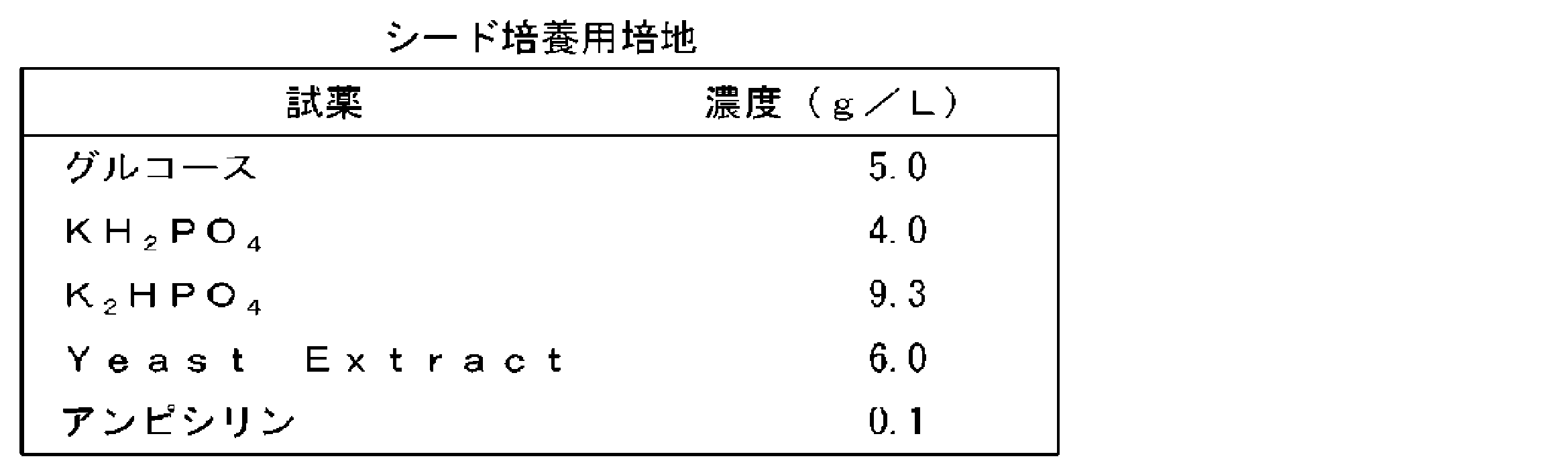
当該シード培養液を、500mLの生産培地(表2)を添加したジャーファーメンターに、OD600が0.05となるように添加した。培養液温度を37℃に保ちながら形質転換大腸菌を培養した。培養液のpH6.9に維持し、培養液中の溶存酸素濃度を、溶存酸素飽和濃度の20%に維持した。
(4) The seed culture solution was added to a jar fermenter to which 500 mL of a production medium (Table 2) had been added so that the OD600 was 0.05. The transformed Escherichia coli was cultured while maintaining the temperature of the culture solution at 37 ° C. The pH of the culture was maintained at 6.9, and the dissolved oxygen concentration in the culture was maintained at 20% of the dissolved oxygen saturation concentration.
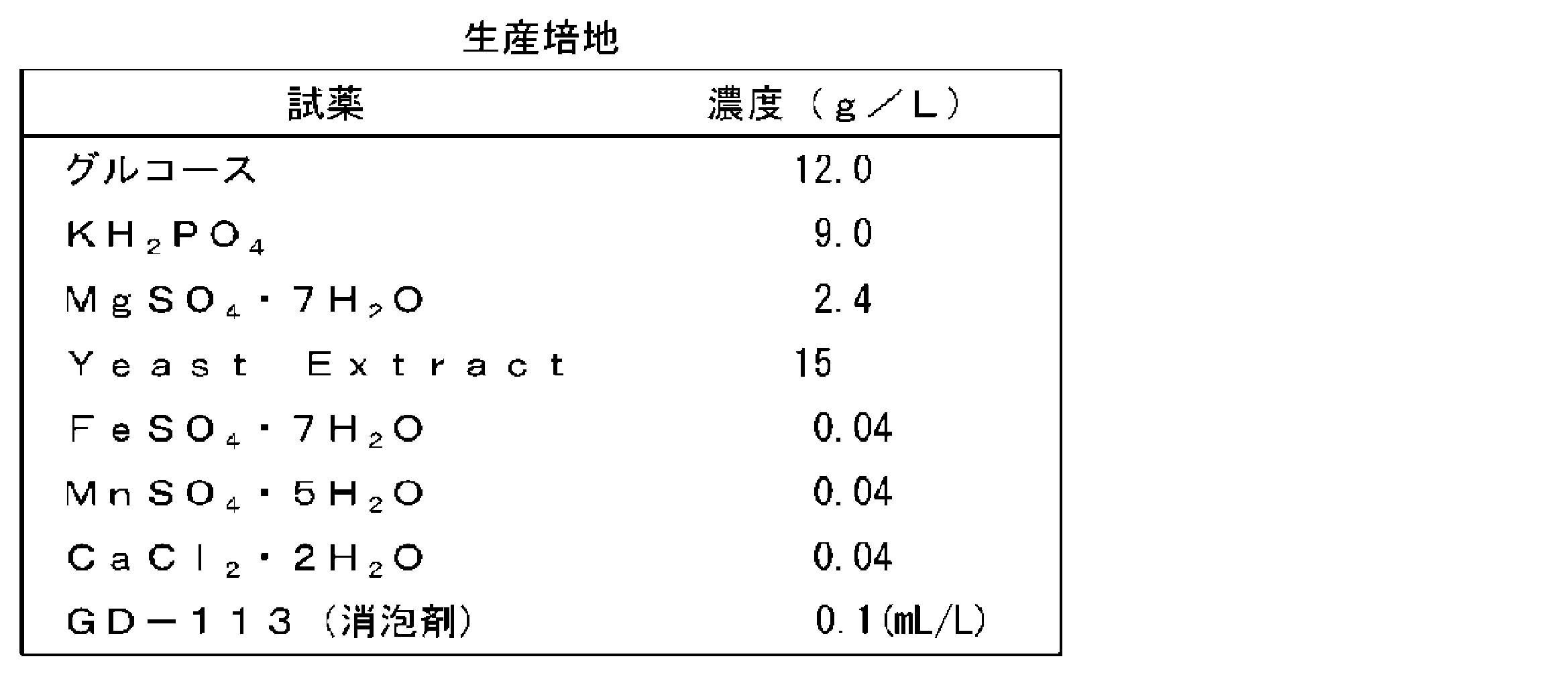
生産培地中のグルコースが完全に消費された直後に、フィード液(グルコース455g/1L、Yeast Extract 120g/1L)を1mL/分の速度で添加した。その後、培養液温度を37℃に保ちながら、pH6.9で培養を20時間継続した。培養液中の溶存酸素濃度を、溶存酸素飽和濃度の20%に維持した。
その後、1Mのイソプロピル-β-チオガラクトピラノシド(IPTG)を培養液に対して終濃度1mMになるよう添加し、目的のタンパク質を発現誘導させた。IPTGを添加後、20時間経過した時点で、培養液を遠心分離し、菌体を回収した。IPTG添加前とIPTG添加後の培養液から調製した菌体を、SDS-PAGEで分析した。IPTG添加に依存した目的とするクモ糸フィブロインのサイズのバンドの出現により、目的とする改変クモ糸フィブロイン「PRT799」又は「PRT966」の発現を確認した。 Immediately after glucose in the production medium was completely consumed, a feed solution (455 g / 1 L of glucose, 120 g / 1 L of Yeast Extract) was added at a rate of 1 mL / min. Thereafter, the culture was continued at pH 6.9 for 20 hours while maintaining the temperature of the culture solution at 37 ° C. The dissolved oxygen concentration in the culture was maintained at 20% of the dissolved oxygen saturation concentration.
Thereafter, 1 M isopropyl-β-thiogalactopyranoside (IPTG) was added to the culture solution to a final concentration of 1 mM to induce the expression of the target protein. Twenty hours after the addition of IPTG, the culture was centrifuged to collect the cells. The cells prepared from the culture solution before and after the addition of IPTG were analyzed by SDS-PAGE. The appearance of the desired spider silk fibroin “PRT799” or “PRT966” was confirmed by the appearance of a band having the size of the desired spider silk fibroin depending on the addition of IPTG.
(3)タンパク質の精製
IPTGを添加してから2時間後に回収した菌体を20mM Tris-HCl buffer(pH7.4)で洗浄した。洗浄後の菌体を約1mMのPMSFを含む20mMTris-HCl緩衝液(pH7.4)に懸濁させ、高圧ホモジナイザー(GEA Niro Soavi社製)で細胞を破砕した。破砕した細胞を遠心分離し、沈殿物を得た。得られた沈殿物を、高純度になるまで20mMTris-HCl緩衝液(pH7.4)で洗浄した。洗浄後の沈殿物を100mg/mLの濃度になるように8M グアニジン緩衝液(8Mグアニジン塩酸塩、10mMリン酸二水素ナトリウム、20mMNaCl、1mMTris-HCl、pH7.0)に懸濁した。懸濁液を60℃で30分間、スターラーで攪拌して、沈殿物を溶解させた。溶解後、透析チューブ(三光純薬株式会社製のセルロースチューブ36/32)を用いて、水で透析を行った。透析後に得られた白色の凝集タンパク質を遠心分離により回収した。回収した凝集タンパク質を凍結乾燥機で乾燥して、改変クモ糸フィブロイン「PRT799」又は「PRT966」を含むタンパク質粉体を得た。 (3) Protein Purification Two hours after the addition of IPTG, the recovered cells were washed with 20 mM Tris-HCl buffer (pH 7.4). The washed cells were suspended in a 20 mM Tris-HCl buffer (pH 7.4) containing about 1 mM PMSF, and the cells were disrupted with a high-pressure homogenizer (GEA Niro Soavi). The disrupted cells were centrifuged to obtain a precipitate. The obtained precipitate was washed with a 20 mM Tris-HCl buffer (pH 7.4) until it became highly pure. The precipitate after washing was suspended in 8 M guanidine buffer (8 M guanidine hydrochloride, 10 mM sodium dihydrogen phosphate, 20 mM NaCl, 1 mM Tris-HCl, pH 7.0) to a concentration of 100 mg / mL. The suspension was stirred with a stirrer at 60 ° C. for 30 minutes to dissolve the precipitate. After dissolution, dialysis was performed with water using a dialysis tube (Cellulose tube 36/32 manufactured by Sanko Junyaku Co., Ltd.). The white aggregated protein obtained after dialysis was recovered by centrifugation. The collected aggregated protein was dried with a freeze dryer to obtain a protein powder containing the modified spider silk fibroin “PRT799” or “PRT966”.
IPTGを添加してから2時間後に回収した菌体を20mM Tris-HCl buffer(pH7.4)で洗浄した。洗浄後の菌体を約1mMのPMSFを含む20mMTris-HCl緩衝液(pH7.4)に懸濁させ、高圧ホモジナイザー(GEA Niro Soavi社製)で細胞を破砕した。破砕した細胞を遠心分離し、沈殿物を得た。得られた沈殿物を、高純度になるまで20mMTris-HCl緩衝液(pH7.4)で洗浄した。洗浄後の沈殿物を100mg/mLの濃度になるように8M グアニジン緩衝液(8Mグアニジン塩酸塩、10mMリン酸二水素ナトリウム、20mMNaCl、1mMTris-HCl、pH7.0)に懸濁した。懸濁液を60℃で30分間、スターラーで攪拌して、沈殿物を溶解させた。溶解後、透析チューブ(三光純薬株式会社製のセルロースチューブ36/32)を用いて、水で透析を行った。透析後に得られた白色の凝集タンパク質を遠心分離により回収した。回収した凝集タンパク質を凍結乾燥機で乾燥して、改変クモ糸フィブロイン「PRT799」又は「PRT966」を含むタンパク質粉体を得た。 (3) Protein Purification Two hours after the addition of IPTG, the recovered cells were washed with 20 mM Tris-HCl buffer (pH 7.4). The washed cells were suspended in a 20 mM Tris-HCl buffer (pH 7.4) containing about 1 mM PMSF, and the cells were disrupted with a high-pressure homogenizer (GEA Niro Soavi). The disrupted cells were centrifuged to obtain a precipitate. The obtained precipitate was washed with a 20 mM Tris-HCl buffer (pH 7.4) until it became highly pure. The precipitate after washing was suspended in 8 M guanidine buffer (8 M guanidine hydrochloride, 10 mM sodium dihydrogen phosphate, 20 mM NaCl, 1 mM Tris-HCl, pH 7.0) to a concentration of 100 mg / mL. The suspension was stirred with a stirrer at 60 ° C. for 30 minutes to dissolve the precipitate. After dissolution, dialysis was performed with water using a dialysis tube (Cellulose tube 36/32 manufactured by Sanko Junyaku Co., Ltd.). The white aggregated protein obtained after dialysis was recovered by centrifugation. The collected aggregated protein was dried with a freeze dryer to obtain a protein powder containing the modified spider silk fibroin “PRT799” or “PRT966”.
2.フィブロイン溶液及びタンパク質繊維
2-1.PRT799
(実施例1-1)
分散工程
混合用の円盤状の回転体を有する混合装置(フロージェットミキサーMW-J-300-S、株式会社粉研パウテックス製)を準備した。この混合装置の回転体を900rpmの回転速度で回転させながら、回転体の回転面上にDMSO及び4質量%の塩化リチウムを含む20℃の溶解液を連続的に供給し、それにより回転面上で溶解液の薄膜を流動させた。回転面の上方の粉体投入口からPRT799を含むタンパク質粉体を供給し、これを回転面上で溶解液に導入した。溶解液はギヤポンプによって15kg/時の流量で供給した。タンパク質粉体はフィーダーによって5kg/時の速度で供給した。これにより、流動する溶解液とタンパク質粉体とを連続的に混合して、これらを含むスラリーを形成させた。 2. 2. Fibroin solution and protein fiber 2-1. PRT799
(Example 1-1)
Dispersion Step A mixing apparatus (flow jet mixer MW-J-300-S, manufactured by Koken Powtex Co., Ltd.) having a disk-shaped rotating body for mixing was prepared. While rotating the rotating body of this mixing apparatus at a rotation speed of 900 rpm, a solution at 20 ° C. containing DMSO and 4% by mass of lithium chloride is continuously supplied onto the rotating surface of the rotating body, whereby the rotating surface is rotated. To flow the thin film of the solution. A protein powder containing PRT799 was supplied from a powder inlet above the rotating surface, and was introduced into the solution on the rotating surface. The solution was supplied by a gear pump at a flow rate of 15 kg / hour. The protein powder was fed by a feeder at a rate of 5 kg / hour. Thus, the flowing solution and the protein powder were continuously mixed to form a slurry containing them.
溶解工程
得られたスラリーを、一軸偏心ねじポンプを用いて、80℃に保持されたインラインミキサー(株式会社ノリタケカンパニーリミテド社製スタティックミキサー:型式SMHEDM-25A(24)/SL)に送液した。スラリーの流量は0.3L/分とした。インラインミキサーには、予め24個のスタティックミキサーエレメントを装着した。インラインミキサー中でスラリーは攪拌されるとともに加熱され、それによりタンパク質粉体が溶解液に溶解した。スラリーがインラインミキサーを通過する時間は1分であり、インラインミキサーから排出されたフィブロイン溶液の温度は70℃であった。 Dissolution Step The obtained slurry was fed to an in-line mixer (static mixer manufactured by Noritake Co., Ltd .: Model SMHEDM-25A (24) / SL) maintained at 80 ° C. using a uniaxial eccentric screw pump. The flow rate of the slurry was 0.3 L / min. The in-line mixer was previously equipped with 24 static mixer elements. The slurry was stirred and heated in the in-line mixer, causing the protein powder to dissolve in the dissolution solution. The time for the slurry to pass through the in-line mixer was 1 minute, and the temperature of the fibroin solution discharged from the in-line mixer was 70 ° C.
得られたスラリーを、一軸偏心ねじポンプを用いて、80℃に保持されたインラインミキサー(株式会社ノリタケカンパニーリミテド社製スタティックミキサー:型式SMHEDM-25A(24)/SL)に送液した。スラリーの流量は0.3L/分とした。インラインミキサーには、予め24個のスタティックミキサーエレメントを装着した。インラインミキサー中でスラリーは攪拌されるとともに加熱され、それによりタンパク質粉体が溶解液に溶解した。スラリーがインラインミキサーを通過する時間は1分であり、インラインミキサーから排出されたフィブロイン溶液の温度は70℃であった。 Dissolution Step The obtained slurry was fed to an in-line mixer (static mixer manufactured by Noritake Co., Ltd .: Model SMHEDM-25A (24) / SL) maintained at 80 ° C. using a uniaxial eccentric screw pump. The flow rate of the slurry was 0.3 L / min. The in-line mixer was previously equipped with 24 static mixer elements. The slurry was stirred and heated in the in-line mixer, causing the protein powder to dissolve in the dissolution solution. The time for the slurry to pass through the in-line mixer was 1 minute, and the temperature of the fibroin solution discharged from the in-line mixer was 70 ° C.
濾過、脱泡及び冷却
得られたフィブロイン溶液を、目開き1μmの焼結金属フィルターで濾過して、不溶物を除去した。次いで、-0.1MPaの減圧下で60分保持することでフィブロイン溶液を脱泡した。その後、フィブロイン溶液を、10℃に保持したインラインミキサー(同上の型式)に送液するころにより、フィブロイン溶液を15℃まで冷却した。冷却されたフィブロイン溶液を貯蔵タンクへ送液した。 Filtration, defoaming and cooling The obtained fibroin solution was filtered with a sintered metal filter having a mesh size of 1 μm to remove insolubles. Next, the fibroin solution was defoamed by being kept under a reduced pressure of -0.1 MPa for 60 minutes. Thereafter, the fibroin solution was cooled to 15 ° C. by sending the fibroin solution to an in-line mixer (model described above) maintained at 10 ° C. The cooled fibroin solution was sent to a storage tank.
得られたフィブロイン溶液を、目開き1μmの焼結金属フィルターで濾過して、不溶物を除去した。次いで、-0.1MPaの減圧下で60分保持することでフィブロイン溶液を脱泡した。その後、フィブロイン溶液を、10℃に保持したインラインミキサー(同上の型式)に送液するころにより、フィブロイン溶液を15℃まで冷却した。冷却されたフィブロイン溶液を貯蔵タンクへ送液した。 Filtration, defoaming and cooling The obtained fibroin solution was filtered with a sintered metal filter having a mesh size of 1 μm to remove insolubles. Next, the fibroin solution was defoamed by being kept under a reduced pressure of -0.1 MPa for 60 minutes. Thereafter, the fibroin solution was cooled to 15 ° C. by sending the fibroin solution to an in-line mixer (model described above) maintained at 10 ° C. The cooled fibroin solution was sent to a storage tank.
紡糸(タンパク質繊維)
冷却後のフィブロイン溶液を紡糸原液として用いた乾湿式紡糸により、改変クモ糸フィブロインを含むフィラメントを得た。乾湿式紡糸の条件は以下のとおりである。
・凝固液(メタノール)の温度:5~10℃
・総延伸倍率:5倍
・乾燥温度:80℃ Spinning (protein fiber)
Filaments containing modified spider silk fibroin were obtained by dry-wet spinning using the cooled fibroin solution as a spinning stock solution. The conditions for dry-wet spinning are as follows.
・ Temperature of coagulation liquid (methanol): 5-10 ° C
・ Total stretching ratio: 5 times ・ Drying temperature: 80 ° C
(実施例1-2)
DMSO及び4質量%の塩化リチウムを含む溶解液に代えて、ギ酸を溶解液として用いたこと以外は実施例1-1と同様の分散工程及び溶解工程により、フィブロイン溶液を調製した。得られたフィブロイン溶液を用いて、実施例1-1と同様にフィラメントを作製した。 (Example 1-2)
A fibroin solution was prepared by the same dispersing step and dissolving step as in Example 1-1 except that formic acid was used as the dissolving solution instead of the dissolving solution containing DMSO and 4% by mass of lithium chloride. Using the obtained fibroin solution, a filament was produced in the same manner as in Example 1-1.
(実施例1-3)
溶解工程に用いるスタティックミキサーエレメントの数を10に変更したこと以外は実施例1-1と同様にして、フィブロイン溶液を調製した。得られたフィブロイン溶液を用いて、実施例1-1と同様にフィラメントを作製した。 (Example 1-3)
A fibroin solution was prepared in the same manner as in Example 1-1, except that the number of static mixer elements used in the dissolving step was changed to 10. Using the obtained fibroin solution, a filament was produced in the same manner as in Example 1-1.
(実施例1-4)
実施例1-1と同様の分散工程により得られたスラリーを、パドル型攪拌翼を備えた100Lのタンクに供給した。タンクジャケットに80℃の温水を通液した。スラリーを攪拌翼で攪拌しながら60分間加熱することによりタンパク質粉体を溶解液に溶解させて、フィブロイン溶液を得た。得られたフィブロイン溶液を用いて、実施例1-1と同様にフィラメントを作製した。 (Example 1-4)
The slurry obtained by the same dispersing process as in Example 1-1 was supplied to a 100 L tank equipped with a paddle-type stirring blade. Hot water at 80 ° C. was passed through the tank jacket. The protein powder was dissolved in the dissolution solution by heating the slurry for 60 minutes while stirring with a stirring blade to obtain a fibroin solution. Using the obtained fibroin solution, a filament was produced in the same manner as in Example 1-1.
(比較例1-1)
パドル型攪拌翼を備えた100Lのタンクに、16kgのタンパク質粉体、及びDMSO及び4質量%の塩化リチウムを含む64kgの溶解液を投入した。これらをタンク中で60分間撹拌して、スラリーを得た。得られたスラリーを用いて、実施例1-1と同様の溶解工程によってフィブロイン溶液を得た。得られたフィブロイン溶液を用いて、実施例1-1と同様にフィラメントを作製した。 (Comparative Example 1-1)
A 100 L tank equipped with a paddle-type stirring blade was charged with 16 kg of protein powder and 64 kg of a solution containing DMSO and 4% by mass of lithium chloride. These were stirred in the tank for 60 minutes to obtain a slurry. Using the obtained slurry, a fibroin solution was obtained by the same dissolving step as in Example 1-1. Using the obtained fibroin solution, a filament was produced in the same manner as in Example 1-1.
(比較例1-2)
比較例1と同様にして、スラリーをタンク内に形成させた。続いて、タンクのジャケットに80℃の温水を通し、スラリーを攪拌しながら60分間加熱することによりタンパク質粉体を溶解液に溶解させて、フィブロイン溶液を得た。得られたフィブロイン溶液を用いて、実施例1-1と同様にフィラメントを作製した。 (Comparative Example 1-2)
A slurry was formed in the tank in the same manner as in Comparative Example 1. Subsequently, hot water of 80 ° C. was passed through the jacket of the tank, and the slurry was heated for 60 minutes while stirring, thereby dissolving the protein powder in the dissolving solution to obtain a fibroin solution. Using the obtained fibroin solution, a filament was produced in the same manner as in Example 1-1.
2-2.PRT966
(実施例2-1)
PRT799を含むタンパク質粉体に代えて、PRT966を含むタンパク質粉体を用いたこと、及び、溶解液としてギ酸を用いたこと以外は実施例1-1と同様の分散工程により、タンパク質粉体及び溶解液を含むスラリーを形成させた。溶解液及びギ酸の供給量を、スラリーにおけるタンパク質の濃度がスラリーの質量を基準として31質量%となるように調整した。
得られたスラリーを、一軸偏心ねじポンプを用いて、80℃に保持されたインラインミキサー(株式会社ノリタケカンパニーリミテド社製スタティックミキサー:型式SMHEDM-25A(24)/SL)に送液した。スラリーの流量は0.3L/分とした。インラインミキサーには、予め24個のスタティックミキサーエレメントを装着した。インラインミキサー中でスラリーは攪拌されるとともに加熱され、それによりタンパク質粉体が溶解液に溶解した。スラリーがインラインミキサーを通過する時間は1分であり、インラインミキサーから排出されたフィブロイン溶液の温度は70℃であった。
得られたフィブロイン溶液を用いて、実施例1-1と同様にフィラメントを作製した。 2-2. PRT966
(Example 2-1)
A protein powder containing PRT966 was used in place of the protein powder containing PRT799, and the same procedure as in Example 1-1 was carried out except that formic acid was used as the dissolving solution. A slurry containing the liquid was formed. The supply amounts of the solution and formic acid were adjusted so that the protein concentration in the slurry was 31% by mass based on the mass of the slurry.
The obtained slurry was sent to an in-line mixer (static mixer manufactured by Noritake Co., Ltd .: Model SMHEDM-25A (24) / SL) maintained at 80 ° C. using a uniaxial eccentric screw pump. The flow rate of the slurry was 0.3 L / min. The in-line mixer was previously equipped with 24 static mixer elements. The slurry was stirred and heated in the in-line mixer, causing the protein powder to dissolve in the dissolution solution. The time for the slurry to pass through the in-line mixer was 1 minute, and the temperature of the fibroin solution discharged from the in-line mixer was 70 ° C.
Using the obtained fibroin solution, a filament was produced in the same manner as in Example 1-1.
(実施例2-2)
実施例2-1と同様の分散工程により得られたスラリーを、パドル型攪拌翼を備えた100Lのタンクに供給した。タンクジャケットに40℃の温水を通液した。スラリーを攪拌翼で攪拌しながら60分間加熱することによりタンパク質粉体を溶解液に溶解させて、フィブロイン溶液を得た。得られたフィブロイン溶液を用いて、実施例1-1と同様にフィラメントを作製した。 (Example 2-2)
The slurry obtained by the same dispersing process as in Example 2-1 was supplied to a 100 L tank equipped with a paddle-type stirring blade. Hot water at 40 ° C. was passed through the tank jacket. The protein powder was dissolved in the dissolution solution by heating the slurry for 60 minutes while stirring with a stirring blade to obtain a fibroin solution. Using the obtained fibroin solution, a filament was produced in the same manner as in Example 1-1.
(比較例2-1)
パドル型攪拌翼を備えた100Lのタンクに、31kgのタンパク質粉体、及び69kgのギ酸を投入した。これらをタンク中で60分間撹拌して、スラリーを得た。得られたスラリーを用いて、実施例2-1と同様のインラインミキサーを用いた溶解工程によってフィブロイン溶液を得た。得られたフィブロイン溶液を用いて、実施例1-1と同様にフィラメントを作製した。 (Comparative Example 2-1)
Into a 100 L tank equipped with a paddle type stirring blade, 31 kg of protein powder and 69 kg of formic acid were charged. These were stirred in the tank for 60 minutes to obtain a slurry. Using the obtained slurry, a fibroin solution was obtained by a dissolving step using the same inline mixer as in Example 2-1. Using the obtained fibroin solution, a filament was produced in the same manner as in Example 1-1.
(比較例2-2)
比較例2-1と同様にして、スラリーをタンク内に形成させた。続いて、タンクのジャケットに40℃の温水を通し、スラリーを攪拌しながら60分間加熱することによりタンパク質粉体を溶解液に溶解させて、フィブロイン溶液を得た。得られたフィブロイン溶液を用いて、実施例1-1と同様にフィラメントを作製した。 (Comparative Example 2-2)
A slurry was formed in the tank in the same manner as in Comparative Example 2-1. Subsequently, warm water of 40 ° C. was passed through the jacket of the tank, and the protein powder was dissolved in the dissolving solution by heating the slurry for 60 minutes while stirring, thereby obtaining a fibroin solution. Using the obtained fibroin solution, a filament was produced in the same manner as in Example 1-1.
3.評価
(1)継粉発生率
目開き2mmの焼結金属フィルターが下部に装着された容量1Lの容器に、1000gのスラリーを入れた。容器内を0.05MPaの窒素で加圧することにより、スラリーにフィルターを通過させた。スラリー中の継粉は、フィルターを通過しなかった。フィルターを通過したスラリーの質量W1(g)を測定した。式:継粉発生率={(1000-W)1/1000}×100によって継粉発生率を算出した。 3. Evaluation (1) Repeated Powder Generation Rate 1000 g of the slurry was placed in a 1-L container equipped with a sintered metal filter having a mesh size of 2 mm at the bottom. The slurry was passed through the filter by pressurizing the inside of the container with nitrogen of 0.05 MPa. The flour in the slurry did not pass through the filter. The mass W 1 (g) of the slurry passed through the filter was measured. Wherein: the lump incidence = {(1000-W) 1 /1000} × 100 was calculated undissolved lumps incidence.
(2)溶解状態(濾過率)
燒結金属フィルターで濾過される前のフィブロイン溶液におけるタンパク質粉体の溶解状態を、濾過率に基づいて評価した。1000gのフィブロイン溶液を、40℃で保持しながら定量ポンプを用いて送液し、濾過面積4.7cm2、目開きが1μmである焼結金属フィルターによって濾過した。フィルターを通過したフィブロイン溶液の質量W2(g)を測定した。式:濾過率=(W2/1000)×100により、濾過率を算出した。濾過率が大きいことは、フィブロインの未溶解分の量が少ないことを意味する。 (2) Dissolution state (filtration rate)
The dissolved state of the protein powder in the fibroin solution before being filtered by the sintered metal filter was evaluated based on the filtration rate. 1000 g of the fibroin solution was fed using a metering pump while maintaining the temperature at 40 ° C., and filtered through a sintered metal filter having a filtration area of 4.7 cm 2 and an opening of 1 μm. The mass W 2 (g) of the fibroin solution passed through the filter was measured. Formula: Filtration rate = (W 2/1000) × 100, was calculated filtration rate. A high filtration rate means that the amount of undissolved portion of fibroin is small.
(3)フィブロイン溶液の粘度
冷却後のフィブロイン溶液の粘度を、粘度測定機(型番:EMS-01S、京都電子工業社製)を用いて測定した。測定条件は以下のとおりである。
・温度:40℃
・測定時間:2分
・プローブ回転数:2000rpm (3) Viscosity of Fibroin Solution The viscosity of the fibroin solution after cooling was measured using a viscometer (model number: EMS-01S, manufactured by Kyoto Electronics Industry Co., Ltd.). The measurement conditions are as follows.
・ Temperature: 40 ° C
-Measurement time: 2 minutes-Probe rotation speed: 2000 rpm
(4)繊維の強度及び伸度
フィラメントの両端をそれぞれ、試験紙片に接着剤で固定した、つかみ冶具間の距離20mm、引張速度10cm/分条件で、引張試験機(インストロン社製、型式:3342)を用いて引張試験を行った。引張試験は、温度20℃、相対湿度65%の環境下で行った。得られた応力-歪み曲線から、強度(破断応力)及び伸度(破断伸度)を求めた。表3に示される強度及び伸度は、比較例1-2を基準とする相対値である。表4に示される強度及び伸度は、比較例2-2を基準とする相対値である。 (4) Strength and elongation of fiber Each end of the filament was fixed to a test paper piece with an adhesive, and a distance between gripping jigs was 20 mm and a tensile speed was 10 cm / min. 3342) to conduct a tensile test. The tensile test was performed in an environment at a temperature of 20 ° C. and a relative humidity of 65%. From the obtained stress-strain curve, strength (rupture stress) and elongation (elongation at break) were determined. The strength and elongation shown in Table 3 are relative values based on Comparative Example 1-2. The strength and elongation shown in Table 4 are relative values based on Comparative Example 2-2.
フィラメントの両端をそれぞれ、試験紙片に接着剤で固定した、つかみ冶具間の距離20mm、引張速度10cm/分条件で、引張試験機(インストロン社製、型式:3342)を用いて引張試験を行った。引張試験は、温度20℃、相対湿度65%の環境下で行った。得られた応力-歪み曲線から、強度(破断応力)及び伸度(破断伸度)を求めた。表3に示される強度及び伸度は、比較例1-2を基準とする相対値である。表4に示される強度及び伸度は、比較例2-2を基準とする相対値である。 (4) Strength and elongation of fiber Each end of the filament was fixed to a test paper piece with an adhesive, and a distance between gripping jigs was 20 mm and a tensile speed was 10 cm / min. 3342) to conduct a tensile test. The tensile test was performed in an environment at a temperature of 20 ° C. and a relative humidity of 65%. From the obtained stress-strain curve, strength (rupture stress) and elongation (elongation at break) were determined. The strength and elongation shown in Table 3 are relative values based on Comparative Example 1-2. The strength and elongation shown in Table 4 are relative values based on Comparative Example 2-2.


表3及び表4に示される評価結果から、溶解液の薄膜を流動させながらスラリーを連続的に形成する分散工程を含む実施例の方法によれば、スラリーの形成における継粉の発生が十分に抑制されることが確認された。また、各実施例では、スラリー中のタンパク質粉体を溶媒に溶解させて、未溶解分の少ないフィブロイン溶液を容易に得ることができた。さらに、各実施例のフィブロイン溶液から、良好な機械物性を有するタンパク質繊維を形成することができた。タンパク質繊維の機械物性は、溶解液の薄膜を流動させながらスラリーを形成する分散工程と、インラインミキサーによる溶解工程との組み合わせによる実施例1-1~1-3のフィブロイン溶液を用いたときに特に優れていた。
According to the evaluation results shown in Tables 3 and 4, according to the method of the example including the dispersion step of continuously forming the slurry while flowing the thin film of the dissolving solution, the generation of the interlocking powder in the formation of the slurry was sufficiently performed. It was confirmed that it was suppressed. In each of the examples, the protein powder in the slurry was dissolved in the solvent, and a fibroin solution with a small amount of undissolved content could be easily obtained. Furthermore, protein fibers having good mechanical properties could be formed from the fibroin solutions of the examples. The mechanical properties of the protein fibers are particularly high when the fibroin solutions of Examples 1-1 to 1-3 are used in combination with a dispersing step of forming a slurry while flowing a thin film of the dissolving solution and a dissolving step using an in-line mixer. It was excellent.
PRT966の繊維の場合、実施例2-1,2-2において、比較例2-1,2-2と比較して伸度が低下する傾向が認められ、これは、実施例2-1,2-2における延伸倍率が相対的に大きいことに主に由来すると考えられる。実施例2-1,2-2の場合、フィブロインの溶解性向上にともなって延伸性が向上し、そのために延伸倍率を高くすることができた。延伸倍率が高いと、より高い強度を有する繊維を得ることができる。実施例2-1,2-2において延伸倍率をより低く設定することによって、より高い伸度を有する繊維が得られると考えられる。
In the case of the fiber of PRT966, the elongation tends to be lower in Examples 2-1 and 2-2 than in Comparative Examples 2-1 and 2-2. This is considered to be mainly due to the relatively large stretching ratio in -2. In the case of Examples 2-1 and 2-2, the stretchability was improved as the solubility of fibroin was improved, and therefore, the draw ratio could be increased. When the draw ratio is high, a fiber having higher strength can be obtained. It is considered that by setting the draw ratio lower in Examples 2-1 and 2-2, a fiber having a higher elongation can be obtained.
1…タンパク質粉体、3…溶解液、3a…薄膜、5…スラリー、7…フィブロイン溶液、10…回転体、11…シャフト、12…制御部、20…混合装置、21…溶解液投入口、23…導入管、25…滞留槽、25A…底面、25B…内周面、30…粉体投入口、40…インラインミキサー、41…配管、43…スタティックミキサーエレメント、45…ジャケット、45a…熱媒入口、45b…熱媒出口、S…回転面。
DESCRIPTION OF SYMBOLS 1 ... Protein powder, 3 ... Dissolution liquid, 3a ... Thin film, 5 ... Slurry, 7 ... Fibroin solution, 10 ... Rotating body, 11 ... Shaft, 12 ... Control part, 20 ... Mixing device, 21 ... Dissolution liquid inlet, Reference numeral 23: introduction pipe, 25: retention tank, 25A: bottom surface, 25B: inner peripheral surface, 30: powder inlet, 40: inline mixer, 41: piping, 43: static mixer element, 45: jacket, 45a: heat medium Inlet, 45b: heat medium outlet, S: rotating surface.
Claims (13)
- 溶媒を含有する溶解液の薄膜を流動させながら、該薄膜に、フィブロインを含むタンパク質粉体を連続的に導入し、それにより前記溶解液及び前記溶解液中に分散した前記タンパク質粉体を含有するスラリーを形成する工程と、
前記スラリー中の前記タンパク質粉体を前記溶解液に溶解させることにより、フィブロイン溶液を形成する工程と、を備える、
フィブロイン溶液を製造する方法。 While flowing the thin film of the solution containing the solvent, the thin film is continuously introduced with the protein powder containing fibroin, thereby containing the solution and the protein powder dispersed in the solution. Forming a slurry;
Forming a fibroin solution by dissolving the protein powder in the slurry in the dissolving solution,
A method for producing a fibroin solution. - 前記溶解液を面上に連続的に供給することにより、前記溶解液の薄膜を前記面上で流動させる、請求項1に記載の方法。 The method according to claim 1, wherein a thin film of the solution is flowed on the surface by continuously supplying the solution on the surface.
- 前記スラリーを形成する前記工程が、
前記溶解液を、定量ポンプにより回転体の回転面上に連続的に供給し、それにより前記回転面上で前記溶解液の薄膜を流動させることと、
前記タンパク質粉体を定量フィーダーにより連続的に供給し、それにより前記タンパク質粉体を前記回転面上の前記薄膜に連続的に導入することと、
を含む、
請求項1に記載の方法。 The step of forming the slurry,
The dissolving solution is continuously supplied on a rotating surface of a rotating body by a metering pump, thereby causing a thin film of the dissolving solution to flow on the rotating surface,
Continuously supplying the protein powder by a quantitative feeder, thereby continuously introducing the protein powder into the thin film on the rotating surface;
including,
The method of claim 1. - 前記スラリーをインラインミキサーで攪拌しながら加熱することにより、前記スラリー中の前記タンパク質粉体を前記溶解液に溶解させる、請求項1~3のいずれか一項に記載の方法。 The method according to any one of claims 1 to 3, wherein the protein powder in the slurry is dissolved in the dissolving solution by heating the slurry with stirring by an inline mixer.
- 前記フィブロイン溶液を、インラインミキサーで攪拌しながら冷却する工程を更に備える、請求項1~4のいずれか一項に記載の方法。 The method according to any one of claims 1 to 4, further comprising a step of cooling the fibroin solution while stirring with an in-line mixer.
- 前記フィブロイン溶液を脱泡する工程を更に備える、請求項1~5のいずれか一項に記載の方法。 The method according to any one of claims 1 to 5, further comprising a step of defoaming the fibroin solution.
- 前記フィブロイン溶液を濾過することにより、不溶物を除去する工程を更に備える、請求項1~6のいずれか一項に記載の方法。 The method according to any one of claims 1 to 6, further comprising a step of removing insolubles by filtering the fibroin solution.
- 前記溶媒が、ジメチルスルホキシド、ギ酸及びヘキサフルオロイソプロパノールからなる群より選ばれる少なくとも1種を含む、請求項1~7のいずれか一項に記載の方法。 The method according to any one of claims 1 to 7, wherein the solvent comprises at least one selected from the group consisting of dimethyl sulfoxide, formic acid, and hexafluoroisopropanol.
- 前記溶解液が無機塩を更に含有する、請求項1~8のいずれか一項に記載の方法。 方法 The method according to any one of claims 1 to 8, wherein the solution further contains an inorganic salt.
- 前記フィブロインが改変フィブロインである、請求1~9のいずれか一項に記載の方法。 方法 The method according to any one of claims 1 to 9, wherein the fibroin is a modified fibroin.
- 前記改変フィブロインが改変クモ糸フィブロインである、請求項10に記載の方法。 The method according to claim 10, wherein the modified fibroin is a modified spider silk fibroin.
- 請求項1~11のいずれか一項に記載の方法によってフィブロイン溶液を得ることと、
前記フィブロイン溶液を成形用原液として用いた成形によって、フィブロインを含有するタンパク質成形体を得ることと、
を含む、タンパク質成形体を製造する方法。 Obtaining a fibroin solution by the method according to any one of claims 1 to 11,
By molding using the fibroin solution as an undiluted solution, to obtain a protein molded body containing fibroin,
A method for producing a protein molded article, comprising: - 前記タンパク質成形体がタンパク質繊維である、請求項12に記載の方法。 The method according to claim 12, wherein the protein molded body is a protein fiber.
Priority Applications (3)
| Application Number | Priority Date | Filing Date | Title |
|---|---|---|---|
| JP2020546241A JPWO2020054873A1 (en) | 2018-09-14 | 2019-09-13 | A method for producing a fibroin solution and a method for producing a protein molded product. |
| US17/274,557 US20220056221A1 (en) | 2018-09-14 | 2019-09-13 | Method for Manufacturing Fibroin Solution and Method for Manufacturing Protein Molded Body |
| EP19860497.7A EP3851480A4 (en) | 2018-09-14 | 2019-09-13 | Method for producing fibroin solution and method for producing protein molded body |
Applications Claiming Priority (2)
| Application Number | Priority Date | Filing Date | Title |
|---|---|---|---|
| JP2018-172728 | 2018-09-14 | ||
| JP2018172728 | 2018-09-14 |
Publications (1)
| Publication Number | Publication Date |
|---|---|
| WO2020054873A1 true WO2020054873A1 (en) | 2020-03-19 |
Family
ID=69777857
Family Applications (1)
| Application Number | Title | Priority Date | Filing Date |
|---|---|---|---|
| PCT/JP2019/036241 WO2020054873A1 (en) | 2018-09-14 | 2019-09-13 | Method for producing fibroin solution and method for producing protein molded body |
Country Status (4)
| Country | Link |
|---|---|
| US (1) | US20220056221A1 (en) |
| EP (1) | EP3851480A4 (en) |
| JP (1) | JPWO2020054873A1 (en) |
| WO (1) | WO2020054873A1 (en) |
Citations (7)
| Publication number | Priority date | Publication date | Assignee | Title |
|---|---|---|---|---|
| JPH07222918A (en) * | 1994-02-14 | 1995-08-22 | Tokushu Kika Kogyo Kk | Method and apparatus for mixing liquid and other substance |
| JP2010013743A (en) * | 2008-07-01 | 2010-01-21 | Shinano Kenshi Co Ltd | Method for producing silk fibroin fiber |
| JP2014129639A (en) | 2011-06-01 | 2014-07-10 | Spiber Inc | Method for manufacturing artificial polypeptide fiber |
| JP2015078451A (en) | 2013-10-15 | 2015-04-23 | 三菱レイヨン株式会社 | Dope and production method thereof |
| JP2015132040A (en) | 2014-01-10 | 2015-07-23 | モンテフィブレ マエ テクノロジース ソシエタ ア レスポンサビリタ リミタータMontefibre Mae Technologies S.R.L. | Process for production of acrylic fibers |
| WO2017094722A1 (en) * | 2015-12-01 | 2017-06-08 | Spiber株式会社 | Method for producing protein solution |
| JP2017119647A (en) * | 2015-12-28 | 2017-07-06 | 株式会社松田養蚕場 | Manufacturing method of high molecular weight silk fibroin aqueous solution, and manufacturing method of high molecular weight silk fibroin powder |
Family Cites Families (6)
| Publication number | Priority date | Publication date | Assignee | Title |
|---|---|---|---|---|
| US3871625A (en) * | 1971-07-24 | 1975-03-18 | Funken Kk | Continuous flow jet mixer |
| US4175873A (en) * | 1976-09-10 | 1979-11-27 | Funken Co., Ltd. | Process and apparatus for mechanically mixing two immiscible liquids and one or more other substances |
| JP5066153B2 (en) * | 2009-09-28 | 2012-11-07 | 株式会社粉研パウテックス | Continuous kneading equipment for powder and liquid |
| EP2970411B1 (en) * | 2013-03-15 | 2018-05-09 | Trustees Of Tufts College | Low molecular weight silk compositions and stabilizing silk compositions |
| HUE048702T2 (en) * | 2014-08-20 | 2020-07-28 | Silk Tech Ltd | Fibroin-derived protein composition |
| US20190031843A1 (en) * | 2016-01-29 | 2019-01-31 | Riken | Molded Article, Production Method for Same, and Method for Improving Toughness of Molded Article |
-
2019
- 2019-09-13 US US17/274,557 patent/US20220056221A1/en not_active Abandoned
- 2019-09-13 WO PCT/JP2019/036241 patent/WO2020054873A1/en unknown
- 2019-09-13 EP EP19860497.7A patent/EP3851480A4/en not_active Withdrawn
- 2019-09-13 JP JP2020546241A patent/JPWO2020054873A1/en not_active Ceased
Patent Citations (7)
| Publication number | Priority date | Publication date | Assignee | Title |
|---|---|---|---|---|
| JPH07222918A (en) * | 1994-02-14 | 1995-08-22 | Tokushu Kika Kogyo Kk | Method and apparatus for mixing liquid and other substance |
| JP2010013743A (en) * | 2008-07-01 | 2010-01-21 | Shinano Kenshi Co Ltd | Method for producing silk fibroin fiber |
| JP2014129639A (en) | 2011-06-01 | 2014-07-10 | Spiber Inc | Method for manufacturing artificial polypeptide fiber |
| JP2015078451A (en) | 2013-10-15 | 2015-04-23 | 三菱レイヨン株式会社 | Dope and production method thereof |
| JP2015132040A (en) | 2014-01-10 | 2015-07-23 | モンテフィブレ マエ テクノロジース ソシエタ ア レスポンサビリタ リミタータMontefibre Mae Technologies S.R.L. | Process for production of acrylic fibers |
| WO2017094722A1 (en) * | 2015-12-01 | 2017-06-08 | Spiber株式会社 | Method for producing protein solution |
| JP2017119647A (en) * | 2015-12-28 | 2017-07-06 | 株式会社松田養蚕場 | Manufacturing method of high molecular weight silk fibroin aqueous solution, and manufacturing method of high molecular weight silk fibroin powder |
Non-Patent Citations (3)
| Title |
|---|
| METHODS IN ENZYMOLOGY, vol. 100, 1983, pages 448 |
| NUCLEIC ACID RES., vol. 10, 1982, pages 6487 |
| See also references of EP3851480A4 |
Also Published As
| Publication number | Publication date |
|---|---|
| US20220056221A1 (en) | 2022-02-24 |
| JPWO2020054873A1 (en) | 2021-08-30 |
| EP3851480A4 (en) | 2022-06-15 |
| EP3851480A1 (en) | 2021-07-21 |
Similar Documents
| Publication | Publication Date | Title |
|---|---|---|
| JP5584932B2 (en) | Method for producing protein fiber | |
| JP7329206B2 (en) | PROTEIN MOLDED PRODUCT AND METHOD FOR PRODUCING THE SAME, PROTEIN SOLUTION, AND PLASTICIZER FOR PROTEIN MOLDED BODY | |
| JP5427322B2 (en) | Polypeptide solution, method for producing artificial polypeptide fiber using the same, and method for purifying polypeptide | |
| EP3385305A1 (en) | Method for producing protein solution | |
| JP6959482B2 (en) | A molded product, a method for manufacturing the molded product, and a method for improving the toughness of the molded product. | |
| JP7436065B2 (en) | Protein recovery method | |
| EP3859056A1 (en) | Protein fiber production method | |
| JP7281139B2 (en) | Method for producing protein fiber | |
| WO2019151424A1 (en) | Fibroin composition, fibroin solution, and method for manufacturing fibroin fiber | |
| WO2019151429A1 (en) | Method for manufacturing protein fiber | |
| WO2020054873A1 (en) | Method for producing fibroin solution and method for producing protein molded body | |
| WO2019065735A1 (en) | Method for producing fiber or fabric | |
| JP7270978B2 (en) | Polypeptide solution, method for producing polypeptide fiber, and artificial polypeptide | |
| WO2020017652A1 (en) | Method for producing protein fiber | |
| JPWO2019066037A1 (en) | Doping solution, products using it, structural protein fiber and its manufacturing method | |
| WO2020067514A1 (en) | Modified spider silk fibroin fiber and method for producing same | |
| JPWO2016163336A1 (en) | Polar solvent solution and method for producing the same | |
| WO2024034631A1 (en) | Modified fibroin | |
| JP2020122249A (en) | Method for producing fibroin fiber and fibroin solution | |
| JP7177453B2 (en) | POLYPEPTIDE, NUCLEIC ACID, MOLDED PRODUCT, COMPOSITION AND METHOD FOR MANUFACTURING SAME, AND PHYSICAL PROPERTY IMPROVEMENT AGENT | |
| JP6803624B2 (en) | Method for manufacturing polymer material molded product | |
| WO2021065812A1 (en) | Doping liquid and method for producing engineered fibroin molded article using same | |
| WO2020067519A1 (en) | Resin molded article and method for producing same | |
| JP2020056120A (en) | Method of producing protein fiber, spinning nozzle, and production apparatus of protein fiber |
Legal Events
| Date | Code | Title | Description |
|---|---|---|---|
| 121 | Ep: the epo has been informed by wipo that ep was designated in this application |
Ref document number: 19860497 Country of ref document: EP Kind code of ref document: A1 |
|
| ENP | Entry into the national phase |
Ref document number: 2020546241 Country of ref document: JP Kind code of ref document: A |
|
| NENP | Non-entry into the national phase |
Ref country code: DE |
|
| ENP | Entry into the national phase |
Ref document number: 2019860497 Country of ref document: EP Effective date: 20210414 |