WO2020054837A1 - リニアソレノイドバルブ - Google Patents
リニアソレノイドバルブ Download PDFInfo
- Publication number
- WO2020054837A1 WO2020054837A1 PCT/JP2019/036063 JP2019036063W WO2020054837A1 WO 2020054837 A1 WO2020054837 A1 WO 2020054837A1 JP 2019036063 W JP2019036063 W JP 2019036063W WO 2020054837 A1 WO2020054837 A1 WO 2020054837A1
- Authority
- WO
- WIPO (PCT)
- Prior art keywords
- land portion
- port
- spool
- output
- output port
- Prior art date
- Legal status (The legal status is an assumption and is not a legal conclusion. Google has not performed a legal analysis and makes no representation as to the accuracy of the status listed.)
- Ceased
Links
Images




Classifications
-
- F—MECHANICAL ENGINEERING; LIGHTING; HEATING; WEAPONS; BLASTING
- F16—ENGINEERING ELEMENTS AND UNITS; GENERAL MEASURES FOR PRODUCING AND MAINTAINING EFFECTIVE FUNCTIONING OF MACHINES OR INSTALLATIONS; THERMAL INSULATION IN GENERAL
- F16K—VALVES; TAPS; COCKS; ACTUATING-FLOATS; DEVICES FOR VENTING OR AERATING
- F16K11/00—Multiple-way valves, e.g. mixing valves; Pipe fittings incorporating such valves
- F16K11/02—Multiple-way valves, e.g. mixing valves; Pipe fittings incorporating such valves with all movable sealing faces moving as one unit
- F16K11/06—Multiple-way valves, e.g. mixing valves; Pipe fittings incorporating such valves with all movable sealing faces moving as one unit comprising only sliding valves, i.e. sliding closure elements
- F16K11/065—Multiple-way valves, e.g. mixing valves; Pipe fittings incorporating such valves with all movable sealing faces moving as one unit comprising only sliding valves, i.e. sliding closure elements with linearly sliding closure members
- F16K11/07—Multiple-way valves, e.g. mixing valves; Pipe fittings incorporating such valves with all movable sealing faces moving as one unit comprising only sliding valves, i.e. sliding closure elements with linearly sliding closure members with cylindrical slides
-
- F—MECHANICAL ENGINEERING; LIGHTING; HEATING; WEAPONS; BLASTING
- F16—ENGINEERING ELEMENTS AND UNITS; GENERAL MEASURES FOR PRODUCING AND MAINTAINING EFFECTIVE FUNCTIONING OF MACHINES OR INSTALLATIONS; THERMAL INSULATION IN GENERAL
- F16K—VALVES; TAPS; COCKS; ACTUATING-FLOATS; DEVICES FOR VENTING OR AERATING
- F16K3/00—Gate valves or sliding valves, i.e. cut-off apparatus with closing members having a sliding movement along the seat for opening and closing
- F16K3/22—Gate valves or sliding valves, i.e. cut-off apparatus with closing members having a sliding movement along the seat for opening and closing with sealing faces shaped as surfaces of solids of revolution
- F16K3/24—Gate valves or sliding valves, i.e. cut-off apparatus with closing members having a sliding movement along the seat for opening and closing with sealing faces shaped as surfaces of solids of revolution with cylindrical valve members
-
- F—MECHANICAL ENGINEERING; LIGHTING; HEATING; WEAPONS; BLASTING
- F16—ENGINEERING ELEMENTS AND UNITS; GENERAL MEASURES FOR PRODUCING AND MAINTAINING EFFECTIVE FUNCTIONING OF MACHINES OR INSTALLATIONS; THERMAL INSULATION IN GENERAL
- F16K—VALVES; TAPS; COCKS; ACTUATING-FLOATS; DEVICES FOR VENTING OR AERATING
- F16K31/00—Actuating devices; Operating means; Releasing devices
- F16K31/02—Actuating devices; Operating means; Releasing devices electric; magnetic
- F16K31/06—Actuating devices; Operating means; Releasing devices electric; magnetic using a magnet, e.g. diaphragm valves, cutting off by means of a liquid
Definitions
- This technology relates to a linear solenoid valve that performs feedback control using output hydraulic pressure output from an output port.
- a hydraulic control device for hydraulically controlling engagement of a clutch or a brake is provided with a linear solenoid valve that regulates and outputs an engagement pressure.
- a linear solenoid valve has an input port, an output port, a discharge port, and a feedback port. A part of the output oil pressure is supplied to the feedback oil chamber as a feedback pressure, and the feedback pressure is applied to the difference in valve area.
- Has a feedback structure for urging the valve in the direction of the electromagnetic portion of the solenoid see Patent Document 1.
- the linear solenoid valve provided with a feedback port as in Patent Literature 1 has a problem that the overall length in the axial direction is increased by the amount of the feedback port.
- the feedback port needs to be provided with a difference in the diameter of the land portion of the spool. Therefore, the feedback port is generally arranged on the end side of the valve portion with respect to the other ports.
- the driving load cannot be reduced, which hinders improvement in fuel efficiency of a vehicle equipped with the linear solenoid valve.
- This linear solenoid valve is A solenoid unit that drives the plunger according to the supplied current;
- a sleeve having an input port, an output port, and a discharge port, each of which is constituted by a through hole and arranged in order in the axial direction,
- a spool slidably inserted into the sleeve,
- the spool has a first land portion and a second land portion, and the axial position is controlled by pressing the plunger, so that the first land portion allows the input port and the output port to be connected to each other.
- the first land portion when the spool is at the first position, blocks input hydraulic pressure input to the input port by a side surface on the input port side in the axial direction, and the spool is moved to the second position by the second port.
- the output hydraulic pressure can be adjusted by allowing the input hydraulic pressure to flow out of the output port, The first land portion and the second land portion so that output hydraulic pressure output from the output port also acts as feedback pressure on the spool in a direction from the output port to the input port in the axial direction of the spool.
- An outer diameter difference was provided between the land portion.
- FIG. 2 is a cross-sectional view showing the linear solenoid valve according to the first embodiment.
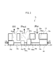
- FIG. 2 is a schematic sectional view showing a valve portion of the linear solenoid valve according to the first embodiment.
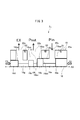
- FIG. 4 is a schematic cross-sectional view showing a valve portion of a linear solenoid valve according to a second embodiment.
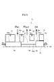
- FIG. 9 is a schematic cross-sectional view illustrating a valve portion of a linear solenoid valve according to a third embodiment.
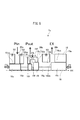
- FIG. 13 is a schematic cross-sectional view illustrating a valve portion of a linear solenoid valve according to a fourth embodiment.
- FIG. 14 is a schematic sectional view showing a valve section of a linear solenoid valve according to a fifth embodiment.
- FIG. 4 is a schematic cross-sectional view showing a valve section of a linear solenoid valve according to a first reference example.
- FIG. 4 is a schematic cross-sectional view showing a valve portion of a linear solenoid valve according to a second reference example.
- FIG. 1 is a sectional view showing a linear solenoid valve according to the first embodiment
- FIG. 2 is a schematic sectional view showing a valve portion of the linear solenoid valve according to the first embodiment.
- the linear solenoid valve 1 is a so-called normally closed type linear solenoid valve, which is used for a hydraulic control device mounted on a vehicle drive device such as an automatic transmission or a hybrid drive device.
- a linear solenoid valve that regulates the engagement pressure supplied to the hydraulic servo of the clutch or brake of the transmission mechanism, a linear solenoid valve that regulates the engagement pressure supplied to the lock-up clutch, and regulates the line pressure Therefore, it is used for a linear solenoid valve or the like that regulates a control pressure according to a throttle opening.
- the linear solenoid valve 1 has a solenoid part 2 and a valve part 3, and the valve part 3 is used by being mounted on a valve body 5 of a hydraulic control device (not shown).
- the solenoid portion 2 is slidably fitted to a coil 6 wound on a bobbin, a first core 7 and a second core 9 mounted so as to cover the coil 6, and a hollow portion of the second core 9.
- a plunger 10 inserted therein, a rod member 11 slidably disposed in a hollow member 8 fitted in the first core 7, and a yoke 12 covering the above members and integrally connected to the valve portion 3.
- the first and second cores 7 and 9, the plunger 10 and the yoke 12 are made of a ferromagnetic material, and the portion between the rod member 11 and the first and second cores 7 and 9 is made of a non-magnetic material. Is supplied from the terminal 13 to the coil 6, a magnetic flux circuit is formed which flows in the order of the first core 7 through the yoke 12, the second core 9, and the plunger 10, and the plunger 10 based on the magnetic flux circuit is formed. The pressing force is transmitted to the spool 16 of the valve section 3 via the rod member 11.
- the valve section 3 has a sleeve 15 and a spool 16.
- the sleeve 15 has a cylindrical shape over substantially the entire length, and an outer peripheral surface 15 a of the sleeve 15 is inserted into the installation hole 5 a of the valve body 5. As a result, it is mounted on the valve body 5.
- the spool 16 is slidably fitted on the inner peripheral surface 15b of the sleeve 15.
- An enlarged diameter portion 15g is formed on one end of the sleeve 15, and the tip of the yoke 12 is caulked to the enlarged diameter portion 15g, so that the solenoid portion 2 and the valve portion 3 are integrally assembled. .
- a cap 17 is screwed and fixed to the other end, which is an end of the sleeve 15, to prevent the spool 16 from coming off inside the sleeve 15, and to end the cap 17 and the end of the spool 16 (details will be described later).
- the spring 19 as an urging member is contracted between the land portion 16d).
- the spring 19 is disposed on the side opposite to the solenoid portion 2 with respect to the spool 16 in the axial direction so as to urge the spool 16 in opposition to the pressing of the plunger 10.
- the opposite end of the spool 16 is in contact with the rod member 11 of the solenoid unit 2, and the spool 16 applies the pressing force of the plunger 10 and the urging force of the spring 19 (and the feedback pressure described later). Is controlled to a balanced position.
- the sleeve 15 has an input port 20a, an output port 20b, and a drain port 20c which are formed by through holes penetrating from the outer peripheral surface 15a to the inner peripheral surface 15b. It communicates with each formed oil passage.
- an input port 20a, an output port 20b, and a drain port 20c (discharge port) are formed in the sleeve 15 in the axial direction AX that is the moving direction of the spool 16 from the solenoid portion 2 side.
- An input oil pressure Pin such as a line pressure is input to the input port 20a, and an output oil pressure Pout serving as an engagement pressure supplied to a hydraulic servo or the like is output from the output port 20b.
- the hydraulic pressure is discharged (EX) from the drain port 20c so as to be released to the atmosphere via the oil passage of the valve body 5.
- the spool 16 has a land portion 16a, a land portion 16b (first land portion), a land portion 16c (second land portion), and a land portion 16d in this order from the side of the solenoid portion 2 in the axial direction.
- Each of the land portions has a smaller diameter than each land portion, and has a shaft portion 16e, a shaft portion 16f, and a shaft portion 16g connecting the land portions.
- Each land portion is formed so as to slide on the inner peripheral surface 15b of the sleeve 15, and more specifically, a sliding surface 16aa which is an outer peripheral surface of the land portion 16a, and a sliding surface which is an outer peripheral surface of the land portion 16b.
- the sliding surface 16ca, which is the outer peripheral surface of the land portion 16c, and the sliding surface 16da, which is the outer peripheral surface of the land portion 16d, are slidable with the inner peripheral surface 15b of the sleeve 15, respectively.
- the lands 16c and 16d are formed to have an outer diameter d1
- the lands 16a and 16b are formed to have an outer diameter d2 larger than the outer diameter d1.
- the lands 16a and 16b have a larger diameter than the lands 16c and 16d.
- a notch N1 is formed at an end of the land 16b on the side of the input port 20a in the axial direction, and a notch N2 is formed at an end of the land 16c on the side of the drain port 20c in the axial direction. Have been. The function of the notches N1 and N2 will be described later.
- An input oil pressure Pin such as a line pressure is input to the input port 20a, and when the solenoid unit 2 shown in FIG. 2 is de-energized, the spool 16 is moved by the urging force of the spring 19 to move the solenoid unit 2 in the axial direction.
- the output port 20b and the drain port 20c communicate with each other, that is, the output hydraulic pressure Pout is discharged to zero pressure.
- the input oil pressure Pin is blocked by the side surface 16bb of the land portion 16b on the side of the input port 20a.
- the land portion 16b opens to the output port 20b, and the inflow from the input port 20a to the output port 20b increases, and the land portion 16c Closes the gap between the output port 20b and the drain port 20c, the amount of discharge from the output port 20b to the drain port 20c decreases, and finally the position where the spool 16 has moved most toward the spring 19 in the axial direction ( At the second position, the input oil pressure Pin of the input port 20a flows out as it is as the output oil pressure Pout of the output port 20b.
- the land portion 16d is disposed on the opposite side of the land portion 16c in the axial direction from the land portion 16b, and is configured to block leakage of hydraulic pressure discharged from the drain port.
- the input hydraulic pressure Pin is accumulated around the shaft portion 16e of the spool 16 by the side surface 16bb of the land portion 16b on the side of the input port 20a and is blocked, and the input hydraulic pressure Pin is gradually moved to the output port 20b as the land portion 16b moves.
- the magnitude of the output oil pressure Pout by letting the input oil pressure Pin flow out, the outflow amount (throttle amount) flowing from the inside of the sleeve 15 toward the output port 20b is adjusted. It is called "spill restriction".
- the output oil pressure Pout When the output oil pressure Pout is increased by moving the spool 16 as described above, as described above, the output of the output port 20b is output to the feedback oil chamber 31 caused by the pressure receiving area difference between the land 16b and the land 16c.
- the hydraulic pressure Pout acts on the spool 16 to act as a feedback pressure corresponding to the output oil pressure Pout toward the solenoid portion 2 in the axial direction, that is, the spool 16 restricts the outflow of the input oil pressure Pin by the output oil pressure Pout. Feedback control is performed in the direction.
- the valve portion 3 1 of the linear solenoid valve 1 according to the first embodiment will be feedback oil chamber 31 is disposed inside the output port 20b in the axial direction.
- valve portion 103 1 of the linear solenoid valve of the first reference example in which the outflow aperture shown in FIG.
- the valve portion 103 1 of the first reference example the input port 120a, the output port 120b, a sleeve 115 having a drain port 120c, and a feedback port 120d, sliding on the inner peripheral surface 115b of the sleeve 115
- the spool 116 is provided with a land portion 116a, a land portion 116b, a land portion 116c, and a land portion 116d in order in the axial direction.
- a shaft portion 116e, a shaft portion 116f, and a shaft portion 116g for connecting the portions are provided.
- a closing plate 115c arranged in a cylindrical shape straddling in the axial direction and an orifice 115d which is a through hole formed in the closing plate 115c are arranged to provide feedback.
- An oil chamber 131 is formed.
- the land portion 16d is the land portion 16b, which is disposed on the outermost end of the plurality of land portions including a land portion 16c, and the land portion 16a, a feedback Since there is no port, that is, there is no land portion constituting the feedback port, the sleeve 15 and the spool 16 can be shortened. Further, since the portion where the feedback pressure acts is the same as the output hydraulic pressure Pout, the sealing performance of the feedback pressure is achieved. a portion of securing is not necessary, even if the minute, the sleeve 15 can be shortened and the spool 16, i.e. it is possible to shorten the valve portion 3 1.
- valve portion 103 1 of the first reference example even if the sleeve 115 and spool 116 to secure the sealing property as the long, the sealing property is limited, axial from the feedback port 120d (feedback oil chamber 131)
- the output hydraulic pressure Pout will leak to both sides in the direction.
- the output hydraulic pressure Pout leaks between the outer peripheral surface 115a of the sleeve 115 and the valve body.
- valve portion 3 1 of the first embodiment (min output port 20b and the feedback oil chamber 31 is shared) minute feedback port is not, the output hydraulic pressure Pout are places is reduced leak, leak amount is small That is, the consumption flow rate of the linear solenoid valve 1 can be reduced.
- the linear solenoid valve 1 according to the first embodiment has a smaller number of parts and can be reduced in price as compared with a case using such two spools.
- valve portion 3 1 As described above, the valve portion 3 1 according to the first embodiment, yet as it is possible to perform a feedback control, it is possible to shorten the axial direction and also possible to achieve a reduction in consumption flow rate Can be.
- the valve unit 3 1 since one in which pressure regulating the output hydraulic pressure Pout by outlet throttle as described above, the input hydraulic pressure Pin is an output port that was blocked by the side surface 16bb of the land portion 16b When the oil flows out to the outlet port 20b, the oil flows from the spool 16 toward the output port 20b in the outer diameter direction. Therefore, the jet flow based on the input oil pressure Pin does not directly hit the side surface 16bc on the side of the output port 20b (the drain port 20c) in the axial direction of the land portion 16b on the side with the larger outer diameter, and acts as a disturbance to the feedback pressure. Therefore, the accuracy of the feedback control can be improved.
- FIG. 3 is a schematic cross-sectional view showing a valve portion of a linear solenoid valve according to the second embodiment.
- Valve part 3 2 of the linear solenoid valve 1 according to the second embodiment is different from the first embodiment, as shown in FIG. 3, the seal ring S1 outer circumferential surface into three sleeves 15, S2, S3 It is provided with.
- the valve portion 3 2 which is inserted into the installation hole 5a of the valve body 5 (see FIG. 1), hydraulic leaks slightly between the outer peripheral surface 15a of the mounting hole 5a and the sleeve 15 of the valve body 5.
- the input hydraulic pressure Pin is input to the input port 20a, and the output hydraulic pressure Pout is output from the output port 20b. Therefore, by sealing both sides of these ports in the axial direction, the flow consumption of the linear solenoid valve 1 is reduced. It is possible to do.
- valve portion 3 2 in the outer periphery of the sleeve 15, the seal ring S1, located on the opposite side of the output port 20b to the input port 20a in the axial direction (first seal ring) in the axial direction
- a seal ring S2 second seal ring
- a seal ring S3 third seal ring
- valve portion 103 1 of the linear solenoid valve of the first reference example since the output hydraulic pressure Pout is supplied to the feedback port 120d, have a seal ring S4, S5 arranged on both sides in the axial direction of the feedback port 120d for example, the leakage caused by the output oil pressure Pout cannot be reduced, and the consumption flow rate cannot be reduced. Therefore, when disposing the seal rings, it is necessary to dispose five seal rings S1, S2, S3, S4, and S5.
- valve portion 3 2 since the feedback port is not may be sealed for the input port 20a and output port 20b, sharing the seal ring S2, 3 pieces of the seal ring S1, Only by arranging S2 and S3, the consumption flow rate can be reduced. Therefore, while the consumption flow rate can be reduced, the number of seal rings can be reduced and the cost can be reduced as compared with the one having the feedback port.
- the linear solenoid valve 1 according to the second embodiment is the same as the first embodiment in other configurations, operations, and effects, and thus the description thereof is omitted.
- FIG. 4 is a schematic sectional view showing a valve portion of a linear solenoid valve according to the third embodiment.
- Valve unit 3 3 of the linear solenoid valve 1 according to the third embodiment is different from the second embodiment, as shown in FIG. 4, as the feedback oil chamber forming portion 15F that forms a feedback oil chamber 31, surrounded
- the sleeve 15 has a portion 15c and an orifice 15d.
- the surrounding portion 15c is disposed astride the land portion 16b and the land portion 16c, and the outer peripheral side of the shaft portion 16f is slid on the sliding surface 16ba of the land portion 16b and the sliding surface 16ca of the land portion 16c. It is annularly formed and arranged so as to surround it, and forms a feedback oil chamber 31 inside.
- An orifice 15d which is a through hole, is formed in the surrounding portion 15c, and is configured to communicate the output port 20b and the feedback oil chamber 31.
- the output oil pressure Pout of the output port 20b is input as the feedback pressure FB. It is configured as follows.
- the surrounding portion 15c is connected by being formed integrally with the sleeve 15, and is fixed so as not to be movable in the axial direction.
- the feedback oil chamber forming portion 15F configured as described above buffers the output oil pressure Pout input to the feedback oil chamber 31 by the orifice 15d even if the output oil pressure Pout pulsates, and stabilizes the fluctuation of the feedback pressure. be able to. Further, even if the land 16b is opened to the output port 20b and the input oil pressure Pin flows out as a jet, the jet does not directly hit the feedback oil chamber 31 by the surrounding portion 15c. It can also be prevented.
- valve portion of the third embodiment 3 3 is suitable for easily pulsation output hydraulic pressure as the performance of the linear solenoid valve 1, suitable for use as outputting large input hydraulic Pin temper pressure in the output hydraulic pressure Pout It is.
- the linear solenoid valve 1 according to the third embodiment is the same as the first and second embodiments in other configurations, operations, and effects, and thus the description thereof is omitted.
- FIG. 5 is a schematic cross-sectional view showing a valve portion of a linear solenoid valve according to a fourth embodiment.
- This valve portion 3 4 of the linear solenoid valve 1 according to the fourth embodiment, as compared with the first to third embodiments, as shown in FIG. 5, when the solenoid portion 2 is de-energized, the spool 16 Is located at a position (first position) on the side of the solenoid portion 2 in the axial direction by the urging force of the spring 19, and the input hydraulic pressure Pin input to the input port 20a is applied to the sliding surface 16ba of the land portion 16b (first land portion). When the spool 16 moves, the land portion 16b opens the input port 20a and flows into the output port 20b as the output hydraulic pressure Pout.
- the input hydraulic pressure Pin is blocked by the sliding surface 16ba of the input port 20a of the land 16b to the input port 20a, and the input hydraulic pressure Pin gradually flows into the output port 20b as the land 16b moves.
- Adjusting the magnitude of the output hydraulic pressure Pout by performing the adjustment is referred to as “inflow restriction” because the flow amount (restriction amount) flowing from the input port 20a toward the inside of the sleeve 15 is adjusted.
- the land portion 16b constitutes has set the pressure receiving area difference consists in diameter than the land portion 16c, these land portion 16b, a feedback oil chamber 31 between 16c.
- a feedback pressure corresponding to the output oil pressure Pout output from the output port 20b acts on the spool 16, that is, the spool 16 is feedback-controlled by the output oil pressure Pout so as to restrict the outflow of the input oil pressure Pin.
- the valve portion 3 4 of the linear solenoid valve 1 according to the fourth embodiment will be feedback oil chamber 31 is disposed inside the output port 20b in the axial direction. Therefore, in the valve unit 3 4 according to the fourth embodiment, since the feedback port is not, despite those which can feedback control, it is possible to shorten the axial direction can be achieved also reduce the consumption flow .
- the valve portion 103 2 of the linear solenoid valve of the second reference example for the outflow aperture shown in FIG.
- the valve portion 103 2 of the second reference example the input port 120a, the output port 120b, a sleeve 115 having a drain port 120c, and a feedback port 120d, sliding on the inner peripheral surface 115b of the sleeve 115
- the spool 116 has a land portion 116a, a land portion 116b, and a land portion 116c in the axial direction, and connects the land portions.
- a shaft portion 116e and a shaft portion 116f are provided.
- a closing plate 115c arranged in a cylindrical shape straddling in the axial direction and an orifice 115d which is a through hole formed in the closing plate 115c are arranged to provide feedback.
- An oil chamber 131 is formed.
- the feedback pressure substantially equal to the output hydraulic pressure Pout acts on the feedback oil chamber 131, the feedback pressure is prevented from leaking between the land portion 116a and the inner peripheral surface 115b of the sleeve 115 and between the land portion 116b and the sleeve 116b. It is necessary to secure the sealing property by long overlap in the axial direction between the inner peripheral surface 115b and the inner peripheral surface 115b, and the axial length of the land portion 116a and the land portion 116b and the sleeve 115 becomes longer.
- the valve unit 3 4 according to the fourth embodiment, the land portion 16c are disposed on the outermost end of the plurality of land portions including a land portion 16b, partial feedback port is not, that is, the feedback port
- the sleeve 15 and the spool 16 can be shortened by the absence of the lands, and the portion where the feedback pressure acts is the same as the output hydraulic pressure Pout. even minute, the sleeve 15 can be shortened and the spool 16, i.e. it is possible to shorten the valve unit 3 4.
- valve portion 103 2 of the second reference example even if the sleeve 115 and spool 116 to secure the sealing property as the long, the sealing property is limited, axial from the feedback port 120d (feedback oil chamber 131)
- the output hydraulic pressure Pout will leak to both sides in the direction.
- the valve portion 3 4 of the fourth embodiment as shown in FIG.
- the minute feedback port is not (min output port 20b and the feedback oil chamber 31 is shared), three seal rings S1, Only by arranging S2 and S3, it is possible to seal between the outer peripheral surface 15a of the sleeve 15 and the installation hole 5a of the valve body 5, so that the consumption flow rate can be reduced. Therefore, while the consumption flow rate can be reduced, the number of seal rings can be reduced and the cost can be reduced as compared with the one having the feedback port.
- the input port 20a is open to a part of the entire circumference. Therefore, the leakage between the inner peripheral surface 15b of the sleeve 15 and the sliding surface 16ba is only a part in the circumferential direction, and the consumption flow rate can be reduced as compared with the structure of the outflow restrictor.
- valve portion 3 4 of the fourth embodiment as compared with the first to third embodiments, the axial position of the input port 20a and the drain port 20c is reversed, i.e. drain to the side of the solenoid portion 2
- the port 20c can be arranged, and the input port 20a can be arranged on the spring 19 side. Therefore, it is possible to cope with a case where the oil passage (oil passage for supplying line pressure or the like) communicating with the input port 20a cannot be arranged on the side of the solenoid unit 2 due to the arrangement of the oil passage in the valve body 5.
- the linear solenoid valve 1 according to the fourth embodiment is the same as the first to third embodiments in other configurations, operations, and effects, and thus the description thereof is omitted.
- FIG. 6 is a schematic sectional view showing a valve portion of a linear solenoid valve according to a fifth embodiment.
- Valve section 35 of the linear solenoid valve 1 according to the fifth embodiment is different from the fourth embodiment, as shown in FIG. 6, as a feedback oil chamber forming portion 15F that forms a feedback oil chamber 31, surrounded The sleeve 15 has a portion 15c and an orifice 15d.
- the spool 16 is located between the land portion (fourth land portion) 16b and the land portion (fifth land portion) 16c in the axial direction and on the inner peripheral side of the output port 20b.
- a land portion 16h (sixth land portion) is formed at a position, and is located at a position on the inner peripheral side of the output port 20b, between the land portion 16h and the land portion 16c in the axial direction.
- Land portions 16i (seventh land portions) are formed so as to be arranged.
- the surrounding portion 15c is disposed astride the land portion 16h and the land portion 16i.
- the outer peripheral side of the shaft portion 16f is slid on the sliding surface 16ha of the land portion 16h and the sliding surface 16ia of the land portion 16i. It is annularly formed and arranged so as to surround it, and forms a feedback oil chamber 31 inside.
- An orifice 15d which is a through hole, is formed in the surrounding portion 15c, and is configured to communicate the output port 20b and the feedback oil chamber 31.
- the output oil pressure Pout of the output port 20b is input as the feedback pressure FB. It is configured as follows.
- the surrounding portion 15c is connected by being formed integrally with the sleeve 15, and is fixed so as not to be movable in the axial direction.
- the feedback oil chamber forming portion 15F configured as described above buffers the output oil pressure Pout input to the feedback oil chamber 31 by the orifice 15d even if the output oil pressure Pout pulsates, and stabilizes the fluctuation of the feedback pressure. be able to. Further, in the valve unit 35 which is configured as a structural diaphragm inlet, the land portion 16b opens the output port 20b, even if the input hydraulic pressure Pin flows into toward the interior of the sleeve 15 as a jet, the jet by the surrounding portion 15c Does not directly hit the feedback oil chamber 31, it is also possible to prevent disturbance in feedback control.
- the linear solenoid valve 1 according to the fifth embodiment is the same as the first to fourth embodiments in other configurations, operations, and effects, and thus the description thereof is omitted.
- This linear solenoid valve (1) (for example, see FIGS. 1 to 4) A solenoid unit (2) for driving a plunger (10) according to the supplied current; A sleeve (15) having an input port (20a), an output port (20b), and a discharge port (20c), each of which is constituted by a through hole and arranged in the axial direction in order; A spool (16) slidably inserted into the sleeve, The spool (16) has a first land portion (16b) and a second land portion (16c), and the position in the axial direction is controlled by pressing the plunger (10), so that the second land portion (16b) is controlled.
- the input port (20a) and the output port (20b) are shut off by one land portion (16b), and the output port (20b) and the discharge port (20c) are communicated by the second land portion (16c). From the first position, the input port (20a) and the output port (20b) are communicated by the first land portion (16b), and the output port (20b) is connected to the output port (20b) by the second land portion (16c). Movable to a second position to shut off the discharge port (20c), When the spool (16) is at the first position, the first land portion (16b) transmits the input oil pressure (Pin) input to the input port (20a) to the input port (20a) in the axial direction.
- Pin input oil pressure
- the linear solenoid valve 1 can be shortened in the axial direction while having the feedback structure, and the flow rate consumed can be reduced.
- the jet flow based on the input hydraulic pressure Pin does not directly hit the side surface 16bc of the land portion 16b, and the feedback pressure is reduced. Acting as disturbance can be prevented, and the accuracy of feedback control can be improved.
- the outer diameter of the first land portion (16b) is larger than the outer diameter of the second land portion (16c).
- the linear solenoid valve (1) (for example, see FIGS. 1 to 4)
- the output hydraulic pressure (Pout) inside the output port (20b) acts on the pressure receiving area difference between the first land portion (16b) and the second land portion (16c), thereby acting as the feedback pressure. I do.
- the linear solenoid valve (1) (for example, see FIG. 4)
- the first land portion is formed inside the output port (20b), slidably abuts the first land portion (16b) and the second land portion (16c), and surrounds the spool (16). (16b) and the surrounding portion (15c) surrounding the second land portion (16c), and the output hydraulic pressure (Pout) formed so as to penetrate through the inside and outside of the surrounding portion (15c).
- a feedback oil chamber forming portion (15F) having an orifice (15d) through which the fluid flows.
- the output oil pressure Pout input to the feedback oil chamber 31 can be buffered by the orifice 15d and the fluctuation of the feedback pressure can be stabilized. Further, even if the input oil pressure Pin flows out to the output port 20b as a jet, the jet does not directly hit the feedback oil chamber 31 by the surrounding portion 15c, so that disturbance in feedback control can be prevented.
- the linear solenoid valve (1) (for example, see FIGS. 1 to 4)
- the spool (16) is disposed on the opposite side of the second land (16c) in the axial direction from the first land (16b), and prevents leakage of hydraulic pressure discharged from the discharge port (20c). It has a third land part (16d) for blocking, The third land portion (16d) is disposed at the end of a plurality of land portions including the first land portion (16b) and the second land portion (16c).
- the land portion 16d is disposed at the end of the land portion of the spool 16, that is, since there is no land portion forming a feedback port as in the related art, the axial length of the linear solenoid valve 1 is reduced. be able to.
- the linear solenoid valve (1) (for example, see FIG. 6) A solenoid unit (2) for driving a plunger (10) according to the supplied current; A sleeve (15) having an input port (20a), an output port (20b), and a discharge port (20c), each of which is constituted by a through hole and arranged in the axial direction in order; A spool (16) slidably inserted into the sleeve, The spool (16) includes a fourth land portion (16b), a fifth land portion (16c), a sixth land portion (16h) arranged at a position facing the output port (20b), and A seventh land (16i) disposed at a position facing the port (20b) and between the sixth land (16h) and the fifth land (16c) in the axial direction.
- the input position (20a) and the output port (20b) are cut off by the fourth land portion (16b) by controlling the axial position by pressing the plunger (10). From a first position where the output port (20b) and the discharge port (20c) communicate with each other by a fifth land portion (16c), the input port (20a) and the output port ( 0b) and being movable by communicating and the fifth land portion (16c) to a second position for blocking said discharge port and said output port (20b) (20c), The fourth land portion (16b) slides the input hydraulic pressure (Pin) input to the input port (20a) with the sleeve (15) when the spool (16) is at the first position.
- Pin input hydraulic pressure
- the input surface (16b) is blocked by the moving surface (16ba), and the input hydraulic pressure (Pin) flows from the input port (20a) by moving the spool (16) toward the second position.
- An output hydraulic pressure (Pout) is formed so as to penetrate the surrounding portion (15c) surrounding the land portion (16h) and the seventh land portion (16i) and the inside and outside of the surrounding portion (15c). And an orifice (15d) into which a feedback oil chamber is formed.
- the output hydraulic pressure (Pout) also acts as feedback pressure on the spool (16) in a direction from the output port (20b) toward the input port (20a) in the axial direction of the spool (16).
- An outer diameter difference is provided between the sixth land portion (16h) and the seventh land portion (16i).
- the linear solenoid valve 1 can be shortened in the axial direction while having the feedback structure, and the flow rate consumed can be reduced. Further, even if the output oil pressure Pout pulsates, the output oil pressure Pout input to the feedback oil chamber 31 can be buffered by the orifice 15d, and the fluctuation of the feedback pressure can be stabilized. Furthermore, even if the input hydraulic pressure Pin flows out to the output port 20b as a jet, the jet does not directly hit the feedback oil chamber 31 by the surrounding portion 15c, so that disturbance in feedback control can be prevented.
- the input oil pressure Pin is a structure that is blocked by the sliding surface 16ba of the land portion 16b, leakage between the inner peripheral surface 15b of the sleeve 15 and the sliding surface 16ba is only a part of the circumferential direction, and the consumption flow rate is reduced. Reduction can be achieved.
- the outer diameter of the seventh land portion (16i) is larger than the outer diameter of the sixth land portion (16h).
- linear solenoid valve (1) (for example, see FIGS. 1 to 4 and FIG. 6) is provided on the opposite side to the solenoid portion (2) with respect to the spool (16) in the axial direction.
- An urging member (19) for urging the spool (16) in opposition to the pressing of the plunger (10) is provided.
- the position of the spool 16 can be controlled by the balance between the pressing of the plunger 10 and the urging force of the spring 19.
- the linear solenoid valve (1) (see FIGS. 3 to 6, for example) A first seal ring (S1) disposed on the outer periphery of the sleeve (15) and opposite to the output port (20b) with respect to the input port (20a) in the axial direction; A second seal ring (S2) disposed on the outer periphery of the sleeve (15) and between the input port (20a) and the output port (20b) in the axial direction; A third seal ring (S3) disposed on the outer periphery of the sleeve (15) and between the output port (20b) and the discharge port (20c) in the axial direction.
- the consumption flow rate can be reduced, the number of seal rings can be reduced and the cost can be reduced as compared with, for example, a device having a feedback port.
- the input port 20a and the output port 20b are disconnected when the solenoid portion 2 is not energized, and the output hydraulic pressure Pout is output from the output port 20b.
- the above description is of a normally closed type in which the output hydraulic pressure is in the non-output state, but the present invention is not limited to this. You may. In this case, the positional relationship in the axial direction between the solenoid portion and the spring for urging the spool is reversed, but the feedback pressure is still applied in the direction in which the input port is closed by the output hydraulic pressure.
- the land portion at the end in the axial direction with which the spring comes into contact is disposed on the side of the solenoid portion, and a feedback port is formed between the land portion at the end and the solenoid portion. It is the same that there is no land portion to be made.
- linear solenoid valve 1 according to the first to fifth embodiments has been described as being provided with the spring 19, but is not limited to this, and has no spring and controls the position of the spool only by the plunger of the valve portion. It does not matter.
- a notch may be formed in the same manner as in the first embodiment.
- the seal ring is disposed on the outer peripheral surface of the sleeve.
- the present invention is not limited to this, and the seal ring is not disposed similarly to the first embodiment. It does not matter.
- the present invention is not limited to this.
- the shape may be any shape.
- the same effect as the orifice is obtained by disposing the orifice 15d and disposing a slight gap between the land portion and the surrounding portion without providing the orifice 15d. Is also good.
- the land portion 16b and the land portion 16c have been described as being separated from each other in the axial direction. However, these land portions are disposed adjacent to each other without any gap, that is, integrated. May be configured.
- the case where the land portion 16h and the land portion 16i are arranged apart from each other in the axial direction has been described. However, these land portions are arranged adjacently without a gap, that is, integrally formed. It may be.
- the case where the surrounding portion 15c is provided so as to slide over the land portion 16h and the land portion 16i has been described. However, for example, the land portion 16h is eliminated, and the surrounding portion 15c becomes the shaft portion. It may be provided so as to slide over the land 16f and the land 16i. In this case, the pressure receiving area due to the outer diameter of the land 16i is a portion where the feedback pressure acts.
- the structure of the linear solenoid valve 1 described in the present embodiment is not limited to the structure shown in FIG. 1 in particular, and various structures may be used as long as a structure in which a feedback pressure acts inside (inside) the output port is provided. The design can be changed.
- the present linear solenoid valve can be used for an automatic transmission, a hybrid drive device, and the like mounted on a vehicle, and is particularly suitable for use in a device that requires a reduction in the axial direction and a reduction in oil consumption flow rate. .
- Pin input hydraulic pressure
- Pout output hydraulic pressure
- S1 first seal ring (seal ring)
- S2 Second seal ring (seal ring)
- S3 Third seal ring (seal ring)
Landscapes
- Engineering & Computer Science (AREA)
- General Engineering & Computer Science (AREA)
- Mechanical Engineering (AREA)
- Magnetically Actuated Valves (AREA)
- Sliding Valves (AREA)
- Multiple-Way Valves (AREA)
Abstract
リニアソレノイドバルブ(1)は、ソレノイド部(2)と、入力ポート(20a)、出力ポート(20b)、及びドレーンポート(20c)を有するスリーブ(15)と、第1ランド部(16b)と第2ランド部(16c)とを有するスプール(16)と、を備える。第1ランド部(16b)は、入力油圧(Pin)を入力ポート(20a)の側の側面(16bb)により堰き止め、スプール(16)が移動することで、入力油圧(Pin)を出力ポート(20b)から流出させて出力油圧(Pout)を調圧する。出力油圧(Pout)が、スプール(16)の軸方向における出力ポート(20b)から入力ポート(20a)に向かう方向へ、スプール(16)にフィードバック圧としても作用するように、第1ランド部(16b)と第2ランド部(16c)とに外径差を設けた。
Description
この技術は、出力ポートから出力する出力油圧によってフィードバック制御を行うリニアソレノイドバルブに関する。
例えば自動変速機やハイブリッド駆動装置などの車両用駆動装置おいては、クラッチやブレーキなどの係合を油圧制御するための油圧制御装置に、係合圧を調圧出力するリニアソレノイドバルブが備えられている。このようなリニアソレノイドバルブは、入力ポート、出力ポート、排出ポート、フィードバックポートを有しており、出力油圧の一部をフィードバック圧としてフィードバック油室に供給して、このフィードバック圧がバルブの面積差によりバルブをソレノイドの電磁部の方向に付勢するフィードバック構造を有している(特許文献1参照)。
しかしながら、上記特許文献1のように、リニアソレノイドバルブにあってフィードバックポートを設けたものは、そのフィードバックポートの分、軸方向の全長が長くなるという問題がある。また、フィードバックポートは、スプールのランド部の径に差を設ける必要があるため、一般的に他のポートに対してバルブ部の端側に配置されることになるが、フィードバックポートにも出力油圧が作用するため、フィードバックポートからバルブ部の端部側に漏れる油の流量が生じるので、リニアソレノイドバルブにおける消費流量の低減の妨げになるという問題があり、消費流量が低減できないと、オイルポンプの駆動負荷が低減できず、そのリニアソレノイドバルブを搭載した車両の燃費向上の妨げとなってしまう。
そこで、フィードバック構造を持ちながら、軸方向の短縮化が可能でかつ消費流量の低減を可能にするリニアソレノイドバルブを提供することを目的とするものである。
本リニアソレノイドバルブは、
供給される電流に応じてプランジャを駆動するソレノイド部と、
それぞれ貫通孔により構成され、軸方向に順に配置された入力ポート、出力ポート、及び排出ポートを有するスリーブと、
前記スリーブに摺動自在に挿入されるスプールと、を備え、
前記スプールは、第1ランド部と、第2ランド部と、を有し、前記プランジャの押圧により軸方向の位置が制御されることで、前記第1ランド部により前記入力ポートと前記出力ポートとを遮断しかつ前記第2ランド部により前記出力ポートと前記排出ポートとを連通する第1位置から、前記第1ランド部により前記入力ポートと前記出力ポートとを連通しかつ前記第2ランド部により前記出力ポートと前記排出ポートとを遮断する第2位置まで移動可能であり、
前記第1ランド部は、前記スプールが前記第1位置にある場合において、前記入力ポートに入力される入力油圧を、軸方向の前記入力ポートの側の側面により堰き止め、前記スプールが前記第2位置に向けて移動することで、前記入力油圧を前記出力ポートから流出させることで出力油圧を調圧可能であり、
前記出力ポートから出力される出力油圧が、前記スプールの軸方向における前記出力ポートから前記入力ポートに向かう方向へ、前記スプールにフィードバック圧としても作用するように、前記第1ランド部と前記第2ランド部とに外径差を設けた。
供給される電流に応じてプランジャを駆動するソレノイド部と、
それぞれ貫通孔により構成され、軸方向に順に配置された入力ポート、出力ポート、及び排出ポートを有するスリーブと、
前記スリーブに摺動自在に挿入されるスプールと、を備え、
前記スプールは、第1ランド部と、第2ランド部と、を有し、前記プランジャの押圧により軸方向の位置が制御されることで、前記第1ランド部により前記入力ポートと前記出力ポートとを遮断しかつ前記第2ランド部により前記出力ポートと前記排出ポートとを連通する第1位置から、前記第1ランド部により前記入力ポートと前記出力ポートとを連通しかつ前記第2ランド部により前記出力ポートと前記排出ポートとを遮断する第2位置まで移動可能であり、
前記第1ランド部は、前記スプールが前記第1位置にある場合において、前記入力ポートに入力される入力油圧を、軸方向の前記入力ポートの側の側面により堰き止め、前記スプールが前記第2位置に向けて移動することで、前記入力油圧を前記出力ポートから流出させることで出力油圧を調圧可能であり、
前記出力ポートから出力される出力油圧が、前記スプールの軸方向における前記出力ポートから前記入力ポートに向かう方向へ、前記スプールにフィードバック圧としても作用するように、前記第1ランド部と前記第2ランド部とに外径差を設けた。
これにより、本リニアソレノイドバルブによると、フィードバック構造を持ちながら、軸方向の短縮化ができ、かつ消費流量の低減を図ることができる。
<第1実施形態>
以下、第1実施形態について図1及び図2を用いて説明する。図1は第1実施形態に係るリニアソレノイドバルブを示す断面図、図2は第1実施形態に係るリニアソレノイドバルブのバルブ部を示す断面模式図である。
以下、第1実施形態について図1及び図2を用いて説明する。図1は第1実施形態に係るリニアソレノイドバルブを示す断面図、図2は第1実施形態に係るリニアソレノイドバルブのバルブ部を示す断面模式図である。
第1実施形態に係るリニアソレノイドバルブ1は、いわゆるノーマルクローズタイプのリニアソレノイドバルブであって、例えば自動変速機やハイブリッド駆動装置等の車両用駆動装置に搭載される油圧制御装置に用いられるものであり、具体的には、変速機構のクラッチやブレーキの油圧サーボに供給する係合圧を調圧するリニアソレノイドバルブ、ロックアップクラッチに供給する係合圧を調圧するリニアソレノイドバルブ、ライン圧を調圧するためにスロットル開度に応じた制御圧を調圧するリニアソレノイドバルブ等に用いられる。
リニアソレノイドバルブ1は、図1に示すように、ソレノイド部2とバルブ部3とを有しており、バルブ部3が図示を省略した油圧制御装置のバルブボディ5に装着されて用いられる。ソレノイド部2は、ボビンに巻回されたコイル6と、そのコイル6を被嵌するように装着した第1コア7及び第2コア9と、第2コア9の中空部に摺動自在に嵌挿したプランジャ10と、第1コア7に嵌挿された中空部材8に摺動自在に配置されたロッド部材11と、上記各部材を覆うようにかつバルブ部3と一体に連結するヨーク12と、を有する。
上記第1及び第2コア7,9、プランジャ10及びヨーク12は、強磁性体からなり、ロッド部材11並びに第1及び第2コア7,9の間部分は非磁性体からなり、制御部からの電流信号がターミナル13からコイル6に供給されると、ヨーク12、第2コア9、プランジャ10を介して第1コア7の順で流れる磁束回路が形成され、該磁束回路に基づくプランジャ10の押圧力がロッド部材11を介してバルブ部3のスプール16に伝えられる。
バルブ部3は、スリーブ15とスプール16とを有しており、スリーブ15は、略々全長に亘って円筒形状からなり、スリーブ15の外周面15aがバルブボディ5の設置孔5aに嵌挿することによりバルブボディ5に装着される。また、スプール16は、上記スリーブ15の内周面15bに摺動自在に嵌挿される。スリーブ15の一端側には膨径した膨径部15gが形成されており、その膨径部15gに上記ヨーク12の先端がカシメられて、ソレノイド部2とバルブ部3とが一体に組付けられる。上記スリーブ15の端部である他端側にはキャップ17が螺合されて固定されており、スプール16をスリーブ15の内部に抜け止めすると共に、キャップ17とスプール16の端部(詳しくは後述するランド部16d)との間に付勢部材としてのスプリング19が縮設されている。言い換えると、スプリング19は、軸方向において、スプール16に対してソレノイド部2とは反対側で、プランジャ10の押圧に対向してスプール16を付勢するように配置されている。そして、スプール16の反対側の端部は、上記ソレノイド部2のロッド部材11に当接しており、スプール16は、上記プランジャ10の押圧力とスプリング19の付勢力(及び後述するフィードバック圧)とが釣り合った位置に制御される。
上記スリーブ15には、その外周面15aから内周面15bに貫通する貫通孔により構成された入力ポート20a、出力ポート20b、ドレーンポート20cが形成されており、それらのポートは、バルブボディ5に形成されたそれぞれの油路に連通している。詳細には、スリーブ15には、ソレノイド部2側からスプール16の移動方向である軸方向AXに対し、順に、入力ポート20a、出力ポート20b、ドレーンポート20c(排出ポート)が形成されている。入力ポート20aにはライン圧等の入力油圧Pinが入力されており、出力ポート20bからは油圧サーボ等に供給する係合圧となる出力油圧Poutが出力される。そして、ドレーンポート20cは、バルブボディ5の油路を介して大気解放される形で油圧が排出(EX)される。
上記スプール16は、軸方向のソレノイド部2の側から順に、ランド部16a、ランド部16b(第1ランド部)、ランド部16c(第2ランド部)、及びランド部16dを有していると共に、それらランド部の間で各ランド部よりも小径に形成され、ランド部同士を連結する軸部16e、軸部16f、及び軸部16gを有している。各ランド部はスリーブ15の内周面15bに摺動するように形成されており、詳細には、ランド部16aの外周面である摺動面16aa、ランド部16bの外周面である摺動面16ba、ランド部16cの外周面である摺動面16ca、ランド部16dの外周面である摺動面16daがそれぞれスリーブ15の内周面15bと摺動自在となるように構成されている。
また、ランド部16c,16dは外径d1を有するように形成され、ランド部16a,16bは外径d1よりも大径な外径d2を有するように形成されている。言い換えると、ランド部16a,16bは、ランド部16c,16dよりも大径に形成されている。これにより、ランド部16bとランド部16cとの間で、外径差(d2-d1)による受圧面積差が設定され、出力ポート20bから出力する出力油圧Poutがスプール16の軸方向における出力ポート20bから入力ポート20aに向かう方向へフィードバック圧としてスプール16に作用するフィードバック油室31として振舞うように構成されている。
なお、ランド部16bの軸方向における入力ポート20aの側の端部にはノッチN1が形成されており、また、ランド部16cの軸方向におけるドレーンポート20cの側の端部にはノッチN2が形成されている。このノッチN1,N2の作用については後述する。
ついで、第1実施形態に係るバルブ部31の動作について図2を用いて説明する。図2に示すように、バルブ部31においてスプール16には、ソレノイド部2のプランジャ10(図1参照)の押圧力F2と、スプリング19(図1参照)の付勢力FSとが作用するように構成されている。入力ポート20aには、例えばライン圧等の入力油圧Pinが入力されており、図2に示すソレノイド部2が非通電となる状態では、スプール16がスプリング19の付勢力によって軸方向のソレノイド部2の側の位置(第1位置)にあり、出力ポート20bとドレーンポート20cとが連通していて、つまり出力油圧Poutは排出されて0圧である。また、この状態では、ランド部16bの入力ポート20aの側の側面16bbにより入力油圧Pinを堰き止めている状態である。
この状態から、ソレノイド部2の押圧力F2によりスプリング19の付勢力FSに抗してスプール16を押圧して軸方向の位置を制御していくと、ランド部16bが出力ポート20bの側に移動するに伴って、まず入力ポート20aと出力ポート20bとがノッチN1(図1参照)により連通し、徐々に入力油圧Pinを出力ポート20bに流出させていくと共に、ランド部16cがドレーンポート20cの側に移動するに伴って、出力ポートとドレーンポート20cとがランド部16cにより閉じられていき、ノッチN2(図1参照)による排出だけとなり、つまり出力ポート20bにおいてドレーンポート20cからの排出量が小さくなると共に入力ポート20aからの流出量が多くなって出力油圧Poutが上昇していく。
その後さらにスプール16を押圧力F2により押圧していくと、ランド部16bが出力ポート20bに対して開いていき、入力ポート20aから出力ポート20bへの流入量が多くなっていくと共に、ランド部16cが出力ポート20bとドレーンポート20cとの間を閉じていき、出力ポート20bからドレーンポート20cへの排出量が小さくなり、最終的にスプール16が軸方向のスプリング19の側に最も移動した位置(第2位置)となると、入力ポート20aの入力油圧Pinが略そのまま出力ポート20bの出力油圧Poutとして流出する状態となる。なお、ランド部16dは、ランド部16cに対してランド部16bとは軸方向の反対側に配置されており、ドレーンポートから排出する油圧の漏出を堰き止めるように構成されている。
なお、このようにランド部16bの入力ポート20aの側の側面16bbによって入力油圧Pinをスプール16の軸部16eの周囲に溜めて堰き止めておき、ランド部16bの移動に伴い出力ポート20bに徐々に入力油圧Pinを流出させていくことで出力油圧Poutの大きさを調圧することを、スリーブ15の内部から出力ポート20bに向かって流出する流出量(絞り量)を調節する構造であるので、「流出絞り」という。
そして、以上のようにスプール16を移動して出力油圧Poutを上昇していくと、上述したようにランド部16bとランド部16cとの受圧面積差によって生じるフィードバック油室31に出力ポート20bの出力油圧Poutが作用して、スプール16に対して軸方向のソレノイド部2の側に向けて出力油圧Poutに応じたフィードバック圧として作用し、つまりスプール16が出力油圧Poutによって入力油圧Pinの流出を絞る方向にフィードバック制御される。このように、本第1実施形態におけるリニアソレノイドバルブ1のバルブ部31では、フィードバック油室31が軸方向における出力ポート20bの内側に配置されていることなる。
ここで、本第1実施形態のリニアソレノイドバルブ1のバルブ部31と、図7に示す流出絞りを行う第1参考例のリニアソレノイドバルブのバルブ部1031と比較する。図7に示すように、第1参考例のバルブ部1031は、入力ポート120a、出力ポート120b、ドレーンポート120c、及びフィードバックポート120dを有するスリーブ115と、スリーブ115の内周面115bに摺動自在に配置されたスプール116とを有して構成されており、スプール116には、軸方向に順にランド部116a、ランド部116b、ランド部116c、及びランド部116dが備えられていると共に各ランド部を連結する軸部116e、軸部116f、及び軸部116gが備えられている。そして、フィードバックポート120dの内部には、軸方向に跨って円筒状に配置された閉塞板115cと、その閉塞板115cに形成された貫通孔であるオリフィス115dとが配置されていることで、フィードバック油室131が形成されている。
図7に示すバルブ部1031では、フィードバックポート120dが備えられている分、バルブ部31に比して軸方向が長くなる。即ち、フィードバック油室131には略出力油圧Poutと同じフィードバック圧が作用するため、フィードバック圧が漏れないように、ランド部116cとスリーブ115の内周面115bとの間、及びランド部116cとスリーブ115の内周面115bとの間が、軸方向に長くオーバラップしてシール性を確保する必要があり、ランド部116c及びランド部116dとスリーブ115との軸方向の長さが長くなる。しかしながら、本第1実施形態に係るバルブ部31では、ランド部16dがランド部16b、ランド部16c、及びランド部16aを含む複数のランド部のうちの最端部に配置されており、フィードバックポートが無い分、つまりフィードバックポートを構成するランド部が無い分、スリーブ15やスプール16も短縮化でき、さらにフィードバック圧が作用する部分が出力油圧Poutと同じ個所であるため、フィードバック圧のシール性を確保する部分が不要となり、その分としても、スリーブ15とスプール16とを短縮化でき、つまりバルブ部31を短縮化することができる。
また、第1参考例のバルブ部1031では、シール性の確保のためにスリーブ115やスプール116を長くしたとしても、シール性には限界があり、フィードバックポート120d(フィードバック油室131)から軸方向の両側に出力油圧Poutが漏れることになる。特にシールリングS4,S5を配置しない場合は、スリーブ115の外周面115aとバルブボディとの間にも出力油圧Poutが漏れることになる。一方、本第1実施形態のバルブ部31では、フィードバックポートが無い分(出力ポート20bとフィードバック油室31とが共用である分)、出力油圧Poutが漏れる箇所が少なくなり、漏れ量が小さくなって、つまりリニアソレノイドバルブ1としての消費流量を低減することができる。
ところで、リニアソレノイドバルブからフィードバックポートを無くすものとしては、特開2009-8158号公報のように、第1スプールの内部に、フィードバック制御を行うための第2スプールを埋め込む手法も考えられるが、本第1実施形態におけるリニアソレノイドバルブ1は、このような2つのスプールを用いるものに比して、部品点数が少なくなり、低価格化も可能となっている。
以上説明したように、本第1実施形態に係るバルブ部31は、フィードバック制御を行うことができるものでありながら、軸方向の短縮化を図ることができ、かつ消費流量の低減も図ることができる。
また、本第1実施形態に係るバルブ部31は、上述したように流出絞りによって出力油圧Poutを調圧するものであるため、ランド部16bの側面16bbで堰き止めていた入力油圧Pinが出力ポート20bに流出される際、スプール16から出力ポート20bに向かって外径方向に油が流れる。そのため、外径が大きい側のランド部16bにおける軸方向の出力ポート20b(ドレーンポート20c)の側の側面16bcに、入力油圧Pinに基づく噴流が直接的に当たることがなく、フィードバック圧に対する外乱として作用することが防止できるので、フィードバック制御の精度も良好なものとすることができる。
<第2実施形態>
ついで、上記第1実施形態を一部変更した第2実施形態について図3を用いて説明する。図3は第2実施形態に係るリニアソレノイドバルブのバルブ部を示す断面模式図である。
ついで、上記第1実施形態を一部変更した第2実施形態について図3を用いて説明する。図3は第2実施形態に係るリニアソレノイドバルブのバルブ部を示す断面模式図である。
本第2実施形態に係るリニアソレノイドバルブ1のバルブ部32は、第1実施形態に比して、図3に示すように、スリーブ15の外周面に3本のシールリングS1,S2,S3を備えたものである。即ち、バルブボディ5の設置孔5a(図1参照)に嵌挿されるバルブ部32には、バルブボディ5の設置孔5aとスリーブ15の外周面15aとの間に油圧が僅かながら漏れる。特に入力ポート20aには入力油圧Pinが入力され、出力ポート20bからは出力油圧Poutが出力されるため、それらポートの軸方向の両側をシールすることで、リニアソレノイドバルブ1としての消費流量を低減することが可能となる。
そこで、バルブ部32には、スリーブ15の外周にあって、軸方向における入力ポート20aに対して出力ポート20bとは反対側に配置されたシールリングS1(第1シールリング)、軸方向における入力ポート20aと出力ポート20bと間に配置されたシールリングS2(第2シールリング)と、軸方向における出力ポート20bとドレーンポート20cと間に配置されたシールリングS3(第3シールリング)とが備えられている。
ここで、第1参考例のリニアソレノイドバルブのバルブ部1031では、フィードバックポート120dにも出力油圧Poutが入力されるため、フィードバックポート120dの軸方向の両側にシールリングS4,S5を配置しなければ、出力油圧Poutによって生じる漏れが低減できず、消費流量の低減が図れない。そのため、シールリングを配置する場合は、5本のシールリングS1,S2,S3,S4,S5を配置する必要がある。
しかしながら、本第2実施形態に係るバルブ部32では、フィードバックポートが無いため、入力ポート20aと出力ポート20bとについてシールすればよく、シールリングS2を共用して、3本のシールリングS1,S2,S3を配置するだけで、消費流量の低減を図ることができる。従って、消費流量を低減することができるものでありながら、フィードバックポートを有するものに比して、シールリングの本数を低減でき、コストダウンを図ることができる。
なお、第2実施形態に係るリニアソレノイドバルブ1は、その他の構成、作用、及び効果について第1実施形態と同様であるので、その説明を省略する。
<第3実施形態>
つづいて、上記第2実施形態を一部変更した第3実施形態について図4を用いて説明する。図4は第3実施形態に係るリニアソレノイドバルブのバルブ部を示す断面模式図である。
つづいて、上記第2実施形態を一部変更した第3実施形態について図4を用いて説明する。図4は第3実施形態に係るリニアソレノイドバルブのバルブ部を示す断面模式図である。
本第3実施形態に係るリニアソレノイドバルブ1のバルブ部33は、第2実施形態に比して、図4に示すように、フィードバック油室31を形成するフィードバック油室形成部15Fとして、包囲部15cとオリフィス15dとをスリーブ15に形成したものである。
包囲部15cは、ランド部16bとランド部16cとに跨って配置され、ランド部16bの摺動面16baとランド部16cの摺動面16caとに摺動するように軸部16fの外周側を囲うように円環状に形成されて配置されており、内部にフィードバック油室31を形成している。また、包囲部15cには貫通孔であるオリフィス15dが形成されており、出力ポート20bとフィードバック油室31とを連通するように構成され、出力ポート20bの出力油圧Poutをフィードバック圧FBとして入力するように構成されている。なお、図示を省略したが、包囲部15cは、スリーブ15と一体的に形成されることで連結されており、軸方向に移動不能に固定されている。
このように構成されたフィードバック油室形成部15Fは、出力油圧Poutが脈動してとしても、フィードバック油室31に入力される出力油圧Poutをオリフィス15dによって緩衝し、フィードバック圧の変動を安定化させることができる。また、ランド部16bが出力ポート20bに対して開いて、入力油圧Pinが噴流として流出しても、包囲部15cによって噴流がフィードバック油室31に直接的に当たることがないため、フィードバック制御の外乱を防止することもできる。
例えば第1及び第2実施形態のように、フィードバック油室形成部15Fを備えていない場合、出力油圧Poutから出力する油圧の大きさ、言い換えると入力ポート20aに入力される油圧の大きさが小さければ、フィードバック圧の変動も小さく、特に問題は無い。要するに第3実施形態のバルブ部33は、リニアソレノイドバルブ1の性能として出力油圧が脈動し易い場合に適しており、大きい入力油圧Pinを調圧して出力油圧Poutとして出力するものとして用いて好適である。
なお、第3実施形態に係るリニアソレノイドバルブ1は、その他の構成、作用、及び効果について第1及び第2実施形態と同様であるので、その説明を省略する。
<第4実施形態>
つづいて、上記第1乃至第3実施形態を一部変更した第4実施形態について図5を用いて説明する。図5は第4実施形態に係るリニアソレノイドバルブのバルブ部を示す断面模式図である。
つづいて、上記第1乃至第3実施形態を一部変更した第4実施形態について図5を用いて説明する。図5は第4実施形態に係るリニアソレノイドバルブのバルブ部を示す断面模式図である。
本第4実施形態に係るリニアソレノイドバルブ1のバルブ部34は、第1乃至第3実施形態に比して、図5に示すように、ソレノイド部2が非通電となる状態では、スプール16がスプリング19の付勢力によって軸方向のソレノイド部2の側の位置(第1位置)にあり、入力ポート20aに入力される入力油圧Pinをランド部16b(第1ランド部)の摺動面16baによって堰き止め、スプール16が移動することによってランド部16bが入力ポート20aを開いて出力ポート20bに出力油圧Poutとして流入させる構造のものである。また、スプール16が最もスプリング19の側に移動した位置(第2位置)となり、入力油圧Pinを略そのまま出力油圧Poutとして出力している状態では、ランド部16c(第2ランド部)の軸方向における出力ポート20bの側の側面16cbによって出力油圧Poutを堰き止め、ソレノイド部2の側に移動するに伴い、ドレーンポート20cに出力ポート20bの出力油圧Poutを流出(排出)させる構造となっている。
なお、このようにランド部16bの入力ポート20aの摺動面16baによって入力油圧Pinを入力ポート20aまでに堰き止めておき、ランド部16bの移動に伴い出力ポート20bに徐々に入力油圧Pinを流入させていくことで出力油圧Poutの大きさを調圧することを、入力ポート20aからスリーブ15の内部に向かって流入する流入量(絞り量)を調節する構造であるので、「流入絞り」という。
バルブ部34において、ランド部16bはランド部16cよりも小径に構成されて受圧面積差を設定しており、これらランド部16b,16cの間にフィードバック油室31を構成している。これにより、出力ポート20bから出力する出力油圧Poutに応じたフィードバック圧がスプール16に作用し、つまりスプール16が出力油圧Poutによって入力油圧Pinの流出を絞るようにフィードバック制御される。このように、本第4実施形態におけるリニアソレノイドバルブ1のバルブ部34でも、フィードバック油室31が軸方向における出力ポート20bの内側に配置されていることなる。従って、第4実施形態に係るバルブ部34においても、フィードバックポートが無いため、フィードバック制御ができるものでありながら、軸方向の短縮化を図ることができ、消費流量の低減も図ることができる。
ここで、本第4実施形態のリニアソレノイドバルブ1のバルブ部34と、図8に示す流出絞りを行う第2参考例のリニアソレノイドバルブのバルブ部1032と比較する。図8に示すように、第2参考例のバルブ部1032は、入力ポート120a、出力ポート120b、ドレーンポート120c、及びフィードバックポート120dを有するスリーブ115と、スリーブ115の内周面115bに摺動自在に配置されたスプール116とを有して構成されており、スプール116には、軸方向に順にランド部116a、ランド部116b、及びランド部116cが備えられていると共に各ランド部を連結する軸部116e、及び軸部116fが備えられている。そして、フィードバックポート120dの内部には、軸方向に跨って円筒状に配置された閉塞板115cと、その閉塞板115cに形成された貫通孔であるオリフィス115dとが配置されていることで、フィードバック油室131が形成されている。
図8に示すバルブ部1032では、フィードバックポート120dが備えられている分、バルブ部34に比して軸方向が長くなる。即ち、フィードバック油室131には略出力油圧Poutと同じフィードバック圧が作用するため、フィードバック圧が漏れないように、ランド部116aとスリーブ115の内周面115bとの間、及びランド部116bとスリーブ115の内周面115bとの間が、軸方向に長くオーバラップしてシール性を確保する必要があり、ランド部116a及びランド部116bとスリーブ115との軸方向の長さが長くなる。しかしながら、本第4実施形態に係るバルブ部34では、ランド部16cがランド部16bを含む複数のランド部のうちの最端部に配置されており、フィードバックポートが無い分、つまりフィードバックポートを構成するランド部が無い分、スリーブ15やスプール16も短縮化でき、さらにフィードバック圧が作用する部分が出力油圧Poutと同じ個所であるため、フィードバック圧のシール性を確保する部分が不要となり、その分としても、スリーブ15とスプール16とを短縮化でき、つまりバルブ部34を短縮化することができる。
また、第2参考例のバルブ部1032では、シール性の確保のためにスリーブ115やスプール116を長くしたとしても、シール性には限界があり、フィードバックポート120d(フィードバック油室131)から軸方向の両側に出力油圧Poutが漏れることになる。特にシールリングS4,S5を配置しない場合は、スリーブ115の外周面115aとバルブボディとの間にも出力油圧Poutが漏れることになる。一方、本第4実施形態のバルブ部34では、図5に示すように、フィードバックポートが無い分(出力ポート20bとフィードバック油室31とが共用である分)、3本のシールリングS1,S2,S3を配置するだけでスリーブ15の外周面15aとバルブボディ5の設置孔5aとの間をシールすることができ、消費流量の低減を図ることができる。従って、消費流量を低減することができるものでありながら、フィードバックポートを有するものに比して、シールリングの本数を低減でき、コストダウンを図ることができる。
なお、第4実施形態に係るバルブ部34においては、上述したように流入絞りを行う構造であるため、ランド部16bが出力ポート20bに対して開く際に流入する入力油圧Pinが噴流として軸部16eの外周に流入し、直接的にランド部16cの側面16cbに作用することがあるため、僅かながらフィードバック制御の精度が第1乃至第3実施形態に比して良好でなくなる可能性がある。一方で、第1乃至第3実施形態における流出量圧の構造では、入力油圧Pinがスプール16のランド部16a,16bの間まで入り込んで堰き止められているので(図2参照)、スリーブ15の内周面15bと摺動面16aa,16baとの間で全周に亘って漏れが生じて消費流量が多くなる可能性がある。
しかしながら、本第4実施形態のように、入力油圧Pinがランド部16bの摺動面16baによって堰き止められる流入絞りの構造では、入力ポート20aが全周のうちの一部に開口している形状であるため、スリーブ15の内周面15bと摺動面16baとの漏れが周方向の一部だけとなり、流出絞りの構造よりも消費流量の低減が図れる。
また、第4実施形態のバルブ部34では、第1乃至第3実施形態に比して、入力ポート20aとドレーンポート20cとの軸方向の位置が逆となり、つまりソレノイド部2の側にドレーンポート20cを配置し、スプリング19の側に入力ポート20aを配置できる。このため、バルブボディ5における油路の取り回しによって、入力ポート20aに連通する油路(ライン圧等を供給する油路)がソレノイド部2の側に配置できない場合にも対応することができる。
なお、第4実施形態に係るリニアソレノイドバルブ1は、その他の構成、作用、及び効果について第1乃至第3実施形態と同様であるので、その説明を省略する。
<第5実施形態>
つづいて、上記第4実施形態を一部変更した第5実施形態について図6を用いて説明する。図6は第5実施形態に係るリニアソレノイドバルブのバルブ部を示す断面模式図である。
つづいて、上記第4実施形態を一部変更した第5実施形態について図6を用いて説明する。図6は第5実施形態に係るリニアソレノイドバルブのバルブ部を示す断面模式図である。
本第5実施形態に係るリニアソレノイドバルブ1のバルブ部35は、第4実施形態に比して、図6に示すように、フィードバック油室31を形成するフィードバック油室形成部15Fとして、包囲部15cとオリフィス15dとをスリーブ15に形成したものである。また、フィードバック油室31を構成するため、スプール16において、ランド部(第4ランド部)16bとランド部(第5ランド部)16cとの軸方向の間にあって出力ポート20bの内周側となる位置にランド部16h(第6ランド部)が配置されるように形成され、さらに、出力ポート20bの内周側となる位置にあって、ランド部16hとランド部16cとの軸方向の間に配置されるようにランド部16i(第7ランド部)が形成されているものである。
包囲部15cは、ランド部16hとランド部16iとに跨って配置され、ランド部16hの摺動面16haとランド部16iの摺動面16iaとに摺動するように軸部16fの外周側を囲うように円環状に形成されて配置されており、内部にフィードバック油室31を形成している。また、包囲部15cには貫通孔であるオリフィス15dが形成されており、出力ポート20bとフィードバック油室31とを連通するように構成され、出力ポート20bの出力油圧Poutをフィードバック圧FBとして入力するように構成されている。なお、図示を省略したが、包囲部15cは、スリーブ15と一体的に形成されることで連結されており、軸方向に移動不能に固定されている。
このように構成されたフィードバック油室形成部15Fは、出力油圧Poutが脈動してとしても、フィードバック油室31に入力される出力油圧Poutをオリフィス15dによって緩衝し、フィードバック圧の変動を安定化させることができる。また、流入絞りの構造として構成されたバルブ部35において、ランド部16bが出力ポート20bに開いて、入力油圧Pinが噴流としてスリーブ15の内部に向けて流入しても、包囲部15cによって噴流がフィードバック油室31に直接的に当たることがないため、フィードバック制御の外乱を防止することもできる。
なお、第5実施形態に係るリニアソレノイドバルブ1は、その他の構成、作用、及び効果について第1乃至第4実施形態と同様であるので、その説明を省略する。
<第1乃至第5実施形態のまとめ>
本リニアソレノイドバルブ(1)は(例えば図1乃至図4参照)、
供給される電流に応じてプランジャ(10)を駆動するソレノイド部(2)と、
それぞれ貫通孔により構成され、軸方向に順に配置された入力ポート(20a)、出力ポート(20b)、及び排出ポート(20c)を有するスリーブ(15)と、
前記スリーブに摺動自在に挿入されるスプール(16)と、を備え、
前記スプール(16)は、第1ランド部(16b)と、第2ランド部(16c)と、を有し、前記プランジャ(10)の押圧により軸方向の位置が制御されることで、前記第1ランド部(16b)により前記入力ポート(20a)と前記出力ポート(20b)とを遮断しかつ前記第2ランド部(16c)により前記出力ポート(20b)と前記排出ポート(20c)とを連通する第1位置から、前記第1ランド部(16b)により前記入力ポート(20a)と前記出力ポート(20b)とを連通しかつ前記第2ランド部(16c)により前記出力ポート(20b)と前記排出ポート(20c)とを遮断する第2位置まで移動可能であり、
前記第1ランド部(16b)は、前記スプール(16)が前記第1位置にある場合において、前記入力ポート(20a)に入力される入力油圧(Pin)を、軸方向の前記入力ポート(20a)の側の側面(16bb)により堰き止め、前記スプール(16)が前記第2位置に向けて移動することで、前記入力油圧(Pin)を前記出力ポート(20b)から流出させることで出力油圧(Pout)を調圧可能であり、
前記出力ポート(20b)から出力される出力油圧(Pout)が、前記スプール(16)の軸方向における前記出力ポート(20b)から前記入力ポート(20a)に向かう方向へ、前記スプール(16)にフィードバック圧としても作用するように、前記第1ランド部(16b)と前記第2ランド部(16c)とに外径差を設けた。
本リニアソレノイドバルブ(1)は(例えば図1乃至図4参照)、
供給される電流に応じてプランジャ(10)を駆動するソレノイド部(2)と、
それぞれ貫通孔により構成され、軸方向に順に配置された入力ポート(20a)、出力ポート(20b)、及び排出ポート(20c)を有するスリーブ(15)と、
前記スリーブに摺動自在に挿入されるスプール(16)と、を備え、
前記スプール(16)は、第1ランド部(16b)と、第2ランド部(16c)と、を有し、前記プランジャ(10)の押圧により軸方向の位置が制御されることで、前記第1ランド部(16b)により前記入力ポート(20a)と前記出力ポート(20b)とを遮断しかつ前記第2ランド部(16c)により前記出力ポート(20b)と前記排出ポート(20c)とを連通する第1位置から、前記第1ランド部(16b)により前記入力ポート(20a)と前記出力ポート(20b)とを連通しかつ前記第2ランド部(16c)により前記出力ポート(20b)と前記排出ポート(20c)とを遮断する第2位置まで移動可能であり、
前記第1ランド部(16b)は、前記スプール(16)が前記第1位置にある場合において、前記入力ポート(20a)に入力される入力油圧(Pin)を、軸方向の前記入力ポート(20a)の側の側面(16bb)により堰き止め、前記スプール(16)が前記第2位置に向けて移動することで、前記入力油圧(Pin)を前記出力ポート(20b)から流出させることで出力油圧(Pout)を調圧可能であり、
前記出力ポート(20b)から出力される出力油圧(Pout)が、前記スプール(16)の軸方向における前記出力ポート(20b)から前記入力ポート(20a)に向かう方向へ、前記スプール(16)にフィードバック圧としても作用するように、前記第1ランド部(16b)と前記第2ランド部(16c)とに外径差を設けた。
これにより、リニアソレノイドバルブ1は、フィードバック構造を持ちながら、軸方向の短縮化を図ることができ、かつ消費流量の低減も図ることができる。また、ランド部16bの側面16bbで堰き止めていた入力油圧Pinが出力ポート20bに流出される際、ランド部16bの側面16bcに入力油圧Pinに基づく噴流が直接的に当たることがなく、フィードバック圧に対する外乱として作用することが防止でき、フィードバック制御の精度も良好なものとすることができる。
また、本リニアソレノイドバルブ(1)は(例えば図1乃至図4参照)、
前記第1ランド部(16b)の外径は、前記第2ランド部(16c)の外径よりも大きい。
前記第1ランド部(16b)の外径は、前記第2ランド部(16c)の外径よりも大きい。
これにより、ランド部16bとランド部16cとに外径差を設けることができる。
また、本リニアソレノイドバルブ(1)は(例えば図1乃至図4参照)、
前記出力ポート(20b)の内部の前記出力油圧(Pout)が、前記第1ランド部(16b)と前記第2ランド部(16c)との受圧面積差に作用することにより、前記フィードバック圧として作用する。
前記出力ポート(20b)の内部の前記出力油圧(Pout)が、前記第1ランド部(16b)と前記第2ランド部(16c)との受圧面積差に作用することにより、前記フィードバック圧として作用する。
これにより、スプール16に出力油圧Poutをフィードバック圧として作用させることができる。
また、本リニアソレノイドバルブ(1)は(例えば図4参照)、
前記出力ポート(20b)の内部に形成され、前記第1ランド部(16b)及び前記第2ランド部(16c)に摺動自在に当接し、前記スプール(16)の周囲における前記第1ランド部(16b)及び前記第2ランド部(16c)との間を包囲する包囲部(15c)と、前記包囲部(15c)の内部と外部とを貫通するように形成されて前記出力油圧(Pout)を流入させるオリフィス(15d)と、を有するフィードバック油室形成部(15F)を備えた。
前記出力ポート(20b)の内部に形成され、前記第1ランド部(16b)及び前記第2ランド部(16c)に摺動自在に当接し、前記スプール(16)の周囲における前記第1ランド部(16b)及び前記第2ランド部(16c)との間を包囲する包囲部(15c)と、前記包囲部(15c)の内部と外部とを貫通するように形成されて前記出力油圧(Pout)を流入させるオリフィス(15d)と、を有するフィードバック油室形成部(15F)を備えた。
これにより、出力油圧Poutが脈動したとしても、フィードバック油室31に入力される出力油圧Poutをオリフィス15dによって緩衝し、フィードバック圧の変動を安定化させることができる。また、入力油圧Pinが噴流として出力ポート20bに流出しても、包囲部15cによって噴流がフィードバック油室31に直接的に当たることがないため、フィードバック制御の外乱を防止することもできる。
また、本リニアソレノイドバルブ(1)は(例えば図1乃至図4参照)、
前記スプール(16)は、前記第2ランド部(16c)に対して前記第1ランド部(16b)とは軸方向の反対側に配置され、前記排出ポート(20c)から排出する油圧の漏出を堰き止める第3ランド部(16d)を有し、
前記第3ランド部(16d)は、前記第1ランド部(16b)と前記第2ランド部(16c)とを含む複数のランド部のうちの最端部に配置された。
前記スプール(16)は、前記第2ランド部(16c)に対して前記第1ランド部(16b)とは軸方向の反対側に配置され、前記排出ポート(20c)から排出する油圧の漏出を堰き止める第3ランド部(16d)を有し、
前記第3ランド部(16d)は、前記第1ランド部(16b)と前記第2ランド部(16c)とを含む複数のランド部のうちの最端部に配置された。
これにより、ランド部16dがスプール16のランド部の中で最端部に配置され、つまり従来のようなフィードバックポートを形成するランド部が無いので、リニアソレノイドバルブ1の軸方向の短縮化を図ることができる。
また、本リニアソレノイドバルブ(1)は(例えば図6参照)、
供給される電流に応じてプランジャ(10)を駆動するソレノイド部(2)と、
それぞれ貫通孔により構成され、軸方向に順に配置された入力ポート(20a)、出力ポート(20b)、及び排出ポート(20c)を有するスリーブ(15)と、
前記スリーブに摺動自在に挿入されるスプール(16)と、を備え、
前記スプール(16)は、第4ランド部(16b)と、第5ランド部(16c)と、前記出力ポート(20b)に対向する位置に配置された第6ランド部(16h)と、前記出力ポート(20b)に対向する位置に配置されると共に軸方向の前記第6ランド部(16h)と前記第5ランド部(16c)との間に配置された第7ランド部(16i)と、を有し、前記プランジャ(10)の押圧により軸方向の位置が制御されることで、前記第4ランド部(16b)により前記入力ポート(20a)と前記出力ポート(20b)とを遮断しかつ前記第5ランド部(16c)により前記出力ポート(20b)と前記排出ポート(20c)とを連通する第1位置から、前記第4ランド部(16b)により前記入力ポート(20a)と前記出力ポート(20b)とを連通しかつ前記第5ランド部(16c)により前記出力ポート(20b)と前記排出ポート(20c)とを遮断する第2位置まで移動可能であり、
前記第4ランド部(16b)は、前記スプール(16)が前記第1位置にある場合において、前記入力ポート(20a)に入力される入力油圧(Pin)を、前記スリーブ(15)との摺動面(16ba)により堰き止め、前記スプール(16)が前記第2位置に向けて移動することで、前記入力油圧(Pin)を前記入力ポート(20a)から流入させることで前記出力ポート(20b)から出力される出力油圧(Pout)を調圧可能に構成され、
さらに、前記出力ポート(20b)の内部に形成され、前記第6ランド部(16h)及び前記第7ランド部(16i)に摺動自在に当接し、前記スプール(16)の周囲における前記第6ランド部(16h)及び前記第7ランド部(16i)との間を包囲する包囲部(15c)と、前記包囲部(15c)の内部と外部とを貫通するように形成されて出力油圧(Pout)を流入させるオリフィス(15d)と、を有するフィードバック油室形成部(15F)を備え、
前記出力油圧(Pout)が、前記スプール(16)の軸方向における前記出力ポート(20b)から前記入力ポート(20a)に向かう方向へ、前記スプール(16)にフィードバック圧としても作用するように、前記第6ランド部(16h)と前記第7ランド部(16i)とに外径差を設けた。
供給される電流に応じてプランジャ(10)を駆動するソレノイド部(2)と、
それぞれ貫通孔により構成され、軸方向に順に配置された入力ポート(20a)、出力ポート(20b)、及び排出ポート(20c)を有するスリーブ(15)と、
前記スリーブに摺動自在に挿入されるスプール(16)と、を備え、
前記スプール(16)は、第4ランド部(16b)と、第5ランド部(16c)と、前記出力ポート(20b)に対向する位置に配置された第6ランド部(16h)と、前記出力ポート(20b)に対向する位置に配置されると共に軸方向の前記第6ランド部(16h)と前記第5ランド部(16c)との間に配置された第7ランド部(16i)と、を有し、前記プランジャ(10)の押圧により軸方向の位置が制御されることで、前記第4ランド部(16b)により前記入力ポート(20a)と前記出力ポート(20b)とを遮断しかつ前記第5ランド部(16c)により前記出力ポート(20b)と前記排出ポート(20c)とを連通する第1位置から、前記第4ランド部(16b)により前記入力ポート(20a)と前記出力ポート(20b)とを連通しかつ前記第5ランド部(16c)により前記出力ポート(20b)と前記排出ポート(20c)とを遮断する第2位置まで移動可能であり、
前記第4ランド部(16b)は、前記スプール(16)が前記第1位置にある場合において、前記入力ポート(20a)に入力される入力油圧(Pin)を、前記スリーブ(15)との摺動面(16ba)により堰き止め、前記スプール(16)が前記第2位置に向けて移動することで、前記入力油圧(Pin)を前記入力ポート(20a)から流入させることで前記出力ポート(20b)から出力される出力油圧(Pout)を調圧可能に構成され、
さらに、前記出力ポート(20b)の内部に形成され、前記第6ランド部(16h)及び前記第7ランド部(16i)に摺動自在に当接し、前記スプール(16)の周囲における前記第6ランド部(16h)及び前記第7ランド部(16i)との間を包囲する包囲部(15c)と、前記包囲部(15c)の内部と外部とを貫通するように形成されて出力油圧(Pout)を流入させるオリフィス(15d)と、を有するフィードバック油室形成部(15F)を備え、
前記出力油圧(Pout)が、前記スプール(16)の軸方向における前記出力ポート(20b)から前記入力ポート(20a)に向かう方向へ、前記スプール(16)にフィードバック圧としても作用するように、前記第6ランド部(16h)と前記第7ランド部(16i)とに外径差を設けた。
これにより、リニアソレノイドバルブ1は、フィードバック構造を持ちながら、軸方向の短縮化を図ることができ、かつ消費流量の低減も図ることができる。また、出力油圧Poutが脈動したとしても、フィードバック油室31に入力される出力油圧Poutをオリフィス15dによって緩衝し、フィードバック圧の変動を安定化させることができる。さらに、入力油圧Pinが噴流として出力ポート20bに流出しても、包囲部15cによって噴流がフィードバック油室31に直接的に当たることがないため、フィードバック制御の外乱を防止することもできる。また、入力油圧Pinがランド部16bの摺動面16baによって堰き止められる構造であるので、スリーブ15の内周面15bと摺動面16baとの漏れが周方向の一部だけとなり、消費流量の低減を図ることができる。
また、本リニアソレノイドバルブ(1)は(例えば図6参照)、
前記第7ランド部(16i)の外径は、前記第6ランド部(16h)の外径よりも大きい。
前記第7ランド部(16i)の外径は、前記第6ランド部(16h)の外径よりも大きい。
これにより、ランド部16iとランド部16hとに外径差を設けることができる。
また、本リニアソレノイドバルブ(1)は(例えば図1乃至図4、及び図6参照)、軸方向において、前記スプール(16)に対して、前記ソレノイド部(2)とは反対側で、前記プランジャ(10)の押圧に対向して前記スプール(16)を付勢する付勢部材(19)を備える。
これにより、プランジャ10の押圧とスプリング19の付勢力との釣り合いによりスプール16の位置を制御することができる。
そして、本リニアソレノイドバルブ(1)は(例えば図3乃至図6参照)、
前記スリーブ(15)の外周にあって、軸方向における前記入力ポート(20a)に対して前記出力ポート(20b)とは反対側に配置された第1シールリング(S1)と、
前記スリーブ(15)の外周にあって、軸方向における前記入力ポート(20a)と前記出力ポート(20b)との間に配置された第2シールリング(S2)と、
前記スリーブ(15)の外周にあって、軸方向における前記出力ポート(20b)と前記排出ポート(20c)との間に配置された第3シールリング(S3)と、を備えた。
前記スリーブ(15)の外周にあって、軸方向における前記入力ポート(20a)に対して前記出力ポート(20b)とは反対側に配置された第1シールリング(S1)と、
前記スリーブ(15)の外周にあって、軸方向における前記入力ポート(20a)と前記出力ポート(20b)との間に配置された第2シールリング(S2)と、
前記スリーブ(15)の外周にあって、軸方向における前記出力ポート(20b)と前記排出ポート(20c)との間に配置された第3シールリング(S3)と、を備えた。
これにより、消費流量を低減することができるものでありながら、例えばフィードバックポートを有するものに比して、シールリングの本数を低減でき、コストダウンを図ることができる。
<他の実施形態の可能性>
なお、以上説明した第1乃至第5実施形態に係るリニアソレノイドバルブ1は、ソレノイド部2が非通電の状態で入力ポート20aと出力ポート20bとの間が遮断されて出力ポート20bから出力油圧Poutが非出力状態となるノーマルクローズタイプのものを説明したが、これに限らず、非通電の状態で入力ポートと出力ポートとが連通して出力油圧が出力状態となるノーマルオープンタイプのものであってもよい。この場合、ソレノイド部とスプールを付勢するスプリングとの軸方向の位置関係が反対になるが、出力油圧によって入力ポートが閉じる方向にフィードバック圧を作用させることに変わりはない。またこの場合、スプリングが当接する軸方向の最端部のランド部が、ソレノイド部の側に配置されることになるが、その最端部のランド部とソレノイド部との間にフィードバックポートを構成するランド部が無いことは同様である。
なお、以上説明した第1乃至第5実施形態に係るリニアソレノイドバルブ1は、ソレノイド部2が非通電の状態で入力ポート20aと出力ポート20bとの間が遮断されて出力ポート20bから出力油圧Poutが非出力状態となるノーマルクローズタイプのものを説明したが、これに限らず、非通電の状態で入力ポートと出力ポートとが連通して出力油圧が出力状態となるノーマルオープンタイプのものであってもよい。この場合、ソレノイド部とスプールを付勢するスプリングとの軸方向の位置関係が反対になるが、出力油圧によって入力ポートが閉じる方向にフィードバック圧を作用させることに変わりはない。またこの場合、スプリングが当接する軸方向の最端部のランド部が、ソレノイド部の側に配置されることになるが、その最端部のランド部とソレノイド部との間にフィードバックポートを構成するランド部が無いことは同様である。
また、第1乃至第5実施形態に係るリニアソレノイドバルブ1は、スプリング19を備えたものを説明したが、これに限らず、スプリングがなく、バルブ部のプランジャだけによってスプールの位置を制御するものであっても構わない。
また、第2乃至第5実施形態においては、ノッチが形成されていないものを一例に説明しているが、第1実施形態と同様にノッチを形成したものであっても構わない。
さらに、第2乃至第5実施形態においては、スリーブの外周面にシールリングを配置したものを説明したが、これに限らず、第1実施形態と同様に、シールリングを配置していないものであっても構わない。
また、第3及び第5実施形態で説明したフィードバック油室形成部15Fにおいて、包囲部15cが環状に形成されてフィードバック油室31を形成するものについて説明したが、これに限らず、包囲部の形状はどのような形状であってもよく、例えばオリフィス15dを設けず、ランド部と包囲部との間を僅かな隙間を存するように配置することで、オリフィスと同様の効果を得るようにしてもよい。
また、第1乃至第3実施形態においては、ランド部16bとランド部16cとが軸方向に離れて配置されているものを説明したが、これらのランド部が隙間無く隣接配置され、つまり一体的に構成されていてもよい。同様に、第5実施形態においては、ランド部16hとランド部16iとが軸方向に離れて配置されているものを説明したが、これらのランド部が隙間無く隣接配置され、つまり一体的に構成されていてもよい。さらに、第5実施形態においては、包囲部15cがランド部16hとランド部16iとに跨って摺動するように設けたものを説明したが、例えばランド部16hを無くし、包囲部15cが軸部16fとランド部16iとに跨って摺動するように設けるようにしてもよく、この場合はランド部16iの外径による受圧面積がフィードバック圧が作用する部分となる。
また、本実施形態で説明したリニアソレノイドバルブ1の構造は、特に図1に示す構造だけに限らず、出力ポートの内部(内側)にフィードバック圧が作用する構造が備えられていれば、種々の設計変更が可能なものである。
本リニアソレノイドバルブは、車両に搭載される自動変速機、ハイブリッド駆動装置等に用いることが可能であり、特に軸方向の短縮化や油の消費流量の低減が求められるものに用いて好適である。
1…リニアソレノイドバルブ
2…ソレノイド部
10…プランジャ
15…スリーブ
15F…フィードバック油室形成部
15c…包囲部
15d…オリフィス
16…スプール
図1乃至図4の16b…第1ランド部(ランド部)
16bb…側面
図1乃至図4の16c…第2ランド部(ランド部)
16d…第3ランド部(ランド部)
図6の16b…第4ランド部(ランド部)
図6の16c…第5ランド部(ランド部)
16h…第6ランド部(ランド部)
16i…第7ランド部(ランド部)
19…付勢部材(スプリング)
20a…入力ポート
20b…出力ポート
20c…排出ポート(ドレーンポート)
Pin…入力油圧
Pout…出力油圧
S1…第1シールリング(シールリング)
S2…第2シールリング(シールリング)
S3…第3シールリング(シールリング)
2…ソレノイド部
10…プランジャ
15…スリーブ
15F…フィードバック油室形成部
15c…包囲部
15d…オリフィス
16…スプール
図1乃至図4の16b…第1ランド部(ランド部)
16bb…側面
図1乃至図4の16c…第2ランド部(ランド部)
16d…第3ランド部(ランド部)
図6の16b…第4ランド部(ランド部)
図6の16c…第5ランド部(ランド部)
16h…第6ランド部(ランド部)
16i…第7ランド部(ランド部)
19…付勢部材(スプリング)
20a…入力ポート
20b…出力ポート
20c…排出ポート(ドレーンポート)
Pin…入力油圧
Pout…出力油圧
S1…第1シールリング(シールリング)
S2…第2シールリング(シールリング)
S3…第3シールリング(シールリング)
Claims (9)
- 供給される電流に応じてプランジャを駆動するソレノイド部と、
それぞれ貫通孔により構成され、軸方向に順に配置された入力ポート、出力ポート、及び排出ポートを有するスリーブと、
前記スリーブに摺動自在に挿入されるスプールと、を備え、
前記スプールは、第1ランド部と、第2ランド部と、を有し、前記プランジャの押圧により軸方向の位置が制御されることで、前記第1ランド部により前記入力ポートと前記出力ポートとを遮断しかつ前記第2ランド部により前記出力ポートと前記排出ポートとを連通する第1位置から、前記第1ランド部により前記入力ポートと前記出力ポートとを連通しかつ前記第2ランド部により前記出力ポートと前記排出ポートとを遮断する第2位置まで移動可能であり、
前記第1ランド部は、前記スプールが前記第1位置にある場合において、前記入力ポートに入力される入力油圧を、軸方向の前記入力ポートの側の側面により堰き止め、前記スプールが前記第2位置に向けて移動することで、前記入力油圧を前記出力ポートから流出させることで出力油圧を調圧可能であり、
前記出力ポートから出力される出力油圧が、前記スプールの軸方向における前記出力ポートから前記入力ポートに向かう方向へ、前記スプールにフィードバック圧としても作用するように、前記第1ランド部と前記第2ランド部とに外径差を設けた、
リニアソレノイドバルブ。 - 前記第1ランド部の外径は、前記第2ランド部の外径よりも大きい、
請求項1に記載のリニアソレノイドバルブ。 - 前記出力ポートの内部の前記出力油圧が、前記第1ランド部と前記第2ランド部との受圧面積差に作用することにより、前記フィードバック圧として作用する、
請求項1又は2に記載のリニアソレノイドバルブ。 - 前記出力ポートの内部に形成され、前記第1ランド部及び前記第2ランド部に摺動自在に当接し、前記スプールの周囲における前記第1ランド部及び前記第2ランド部との間を包囲する包囲部と、前記包囲部の内部と外部とを貫通するように形成されて前記出力油圧を流入させるオリフィスと、を有するフィードバック油室形成部を備えた、
請求項1乃至3の何れか1項に記載のリニアソレノイドバルブ。 - 前記スプールは、前記第2ランド部に対して前記第1ランド部とは軸方向の反対側に配置され、前記排出ポートから排出する油圧の漏出を堰き止める第3ランド部を有し、
前記第3ランド部は、前記第1ランド部と前記第2ランド部とを含む複数のランド部のうちの最端部に配置された、
請求項1乃至4の何れか1項に記載のリニアソレノイドバルブ。 - 供給される電流に応じてプランジャを駆動するソレノイド部と、
それぞれ貫通孔により構成され、軸方向に順に配置された入力ポート、出力ポート、及び排出ポートを有するスリーブと、
前記スリーブに摺動自在に挿入されるスプールと、を備え、
前記スプールは、第4ランド部と、第5ランド部と、前記出力ポートに対向する位置に配置された第6ランド部と、前記出力ポートに対向する位置に配置されると共に軸方向の前記第6ランド部と前記第5ランド部との間に配置された第7ランド部と、を有し、前記プランジャの押圧により軸方向の位置が制御されることで、前記第4ランド部により前記入力ポートと前記出力ポートとを遮断しかつ前記第5ランド部により前記出力ポートと前記排出ポートとを連通する第1位置から、前記第4ランド部により前記入力ポートと前記出力ポートとを連通しかつ前記第5ランド部により前記出力ポートと前記排出ポートとを遮断する第2位置まで移動可能であり、
前記第4ランド部は、前記スプールが前記第1位置にある場合において、前記入力ポートに入力される入力油圧を、前記スリーブとの摺動面により堰き止め、前記スプールが前記第2位置に向けて移動することで、前記入力油圧を前記入力ポートから流入させることで前記出力ポートから出力される出力油圧を調圧可能に構成され、
さらに、前記出力ポートの内部に形成され、前記第6ランド部及び前記第7ランド部に摺動自在に当接し、前記スプールの周囲における前記第6ランド部及び前記第7ランド部との間を包囲する包囲部と、前記包囲部の内部と外部とを貫通するように形成されて出力油圧を流入させるオリフィスと、を有するフィードバック油室形成部を備え、
前記出力油圧が、前記スプールの軸方向における前記出力ポートから前記入力ポートに向かう方向へ、前記スプールにフィードバック圧としても作用するように、前記第6ランド部と前記第7ランド部とに外径差を設けた、
リニアソレノイドバルブ。 - 前記第7ランド部の外径は、前記第6ランド部の外径よりも大きい、
請求項6に記載のリニアソレノイドバルブ。 - 軸方向において、前記スプールに対して、前記ソレノイド部とは反対側で、前記プランジャの押圧に対向して前記スプールを付勢する付勢部材を備えた、
請求項1乃至7の何れか1項に記載のリニアソレノイドバルブ。 - 前記スリーブの外周にあって、軸方向における前記入力ポートに対して前記出力ポートとは反対側に配置された第1シールリングと、
前記スリーブの外周にあって、軸方向における前記入力ポートと前記出力ポートとの間に配置された第2シールリングと、
前記スリーブの外周にあって、軸方向における前記出力ポートと前記排出ポートとの間に配置された第3シールリングと、を備えた、
請求項1乃至8のいずれか1項に記載のリニアソレノイドバルブ。
Applications Claiming Priority (2)
| Application Number | Priority Date | Filing Date | Title |
|---|---|---|---|
| JP2018171957A JP2020041687A (ja) | 2018-09-13 | 2018-09-13 | リニアソレノイドバルブ |
| JP2018-171957 | 2018-09-13 |
Publications (1)
| Publication Number | Publication Date |
|---|---|
| WO2020054837A1 true WO2020054837A1 (ja) | 2020-03-19 |
Family
ID=69777200
Family Applications (1)
| Application Number | Title | Priority Date | Filing Date |
|---|---|---|---|
| PCT/JP2019/036063 Ceased WO2020054837A1 (ja) | 2018-09-13 | 2019-09-13 | リニアソレノイドバルブ |
Country Status (2)
| Country | Link |
|---|---|
| JP (1) | JP2020041687A (ja) |
| WO (1) | WO2020054837A1 (ja) |
Families Citing this family (3)
| Publication number | Priority date | Publication date | Assignee | Title |
|---|---|---|---|---|
| DE112020004707T5 (de) | 2019-09-30 | 2022-06-23 | Aisin Corporation | Robotervorrichtung und flüssigkeitszufuhrvorrichtung |
| WO2021065453A1 (ja) | 2019-09-30 | 2021-04-08 | アイシン・エィ・ダブリュ株式会社 | ロボット装置および液体供給装置 |
| JP7566607B2 (ja) * | 2020-12-10 | 2024-10-15 | 住友重機械工業株式会社 | スプール型流量制御弁およびその製造方法 |
Citations (2)
| Publication number | Priority date | Publication date | Assignee | Title |
|---|---|---|---|---|
| JP2011214693A (ja) * | 2010-04-01 | 2011-10-27 | Denso Corp | 電磁スプール弁 |
| JP2012122609A (ja) * | 2010-11-19 | 2012-06-28 | Denso Corp | 油圧調整弁 |
-
2018
- 2018-09-13 JP JP2018171957A patent/JP2020041687A/ja active Pending
-
2019
- 2019-09-13 WO PCT/JP2019/036063 patent/WO2020054837A1/ja not_active Ceased
Patent Citations (2)
| Publication number | Priority date | Publication date | Assignee | Title |
|---|---|---|---|---|
| JP2011214693A (ja) * | 2010-04-01 | 2011-10-27 | Denso Corp | 電磁スプール弁 |
| JP2012122609A (ja) * | 2010-11-19 | 2012-06-28 | Denso Corp | 油圧調整弁 |
Also Published As
| Publication number | Publication date |
|---|---|
| JP2020041687A (ja) | 2020-03-19 |
Similar Documents
| Publication | Publication Date | Title |
|---|---|---|
| US7458395B2 (en) | Low leak poppet solenoid | |
| US20140026985A1 (en) | Electro-proportional pilot operated poppet valve with pressure compensation | |
| US6161585A (en) | High flow proportional pressure reducing valve | |
| KR102113102B1 (ko) | 직접 작용식 솔레노이드 작동기 | |
| US6615869B2 (en) | Solenoid valve | |
| US9841111B2 (en) | Solenoid valve | |
| US20070267077A1 (en) | Fluid pressure control apparatus | |
| US6198369B1 (en) | Proportional actuator for proportional control devices | |
| WO2020054837A1 (ja) | リニアソレノイドバルブ | |
| WO2009119609A1 (ja) | ブリード型電磁弁 | |
| US8534639B1 (en) | Solenoid valve with a digressively damped armature | |
| US20190203846A1 (en) | High flow high pressure hydraulic solenoid valve for automatic transmission | |
| JPH084937A (ja) | 流体制御弁 | |
| US20040129322A1 (en) | Pressure control valve for controlling two pressure load paths | |
| US20180195627A1 (en) | Combination valve and bidirectional flow control valve using the same | |
| US20190178406A1 (en) | High flow high pressure hydraulic solenoid valve for automatic transmission | |
| JP5993000B2 (ja) | 弁、特に圧力調整弁又は圧力制限弁 | |
| JP4492649B2 (ja) | ブリード式バルブ装置 | |
| US20090057594A1 (en) | Bleed valve apparatus | |
| JP4066686B2 (ja) | 電磁制御弁 | |
| US20090065075A1 (en) | Pressure control valve | |
| JPS62261782A (ja) | 電磁比例油圧制御弁 | |
| US6557823B2 (en) | Electromagnetic valve | |
| JP2006349142A (ja) | 低漏洩ポペット電磁弁 | |
| JP7427349B2 (ja) | スプールバルブ |
Legal Events
| Date | Code | Title | Description |
|---|---|---|---|
| 121 | Ep: the epo has been informed by wipo that ep was designated in this application |
Ref document number: 19859731 Country of ref document: EP Kind code of ref document: A1 |
|
| NENP | Non-entry into the national phase |
Ref country code: DE |
|
| 122 | Ep: pct application non-entry in european phase |
Ref document number: 19859731 Country of ref document: EP Kind code of ref document: A1 |