WO2020054589A1 - Air guide structure - Google Patents
Air guide structure Download PDFInfo
- Publication number
- WO2020054589A1 WO2020054589A1 PCT/JP2019/035119 JP2019035119W WO2020054589A1 WO 2020054589 A1 WO2020054589 A1 WO 2020054589A1 JP 2019035119 W JP2019035119 W JP 2019035119W WO 2020054589 A1 WO2020054589 A1 WO 2020054589A1
- Authority
- WO
- WIPO (PCT)
- Prior art keywords
- air guide
- air
- vehicle
- radiator
- lid
- Prior art date
Links
Images

Classifications
-
- B—PERFORMING OPERATIONS; TRANSPORTING
- B60—VEHICLES IN GENERAL
- B60K—ARRANGEMENT OR MOUNTING OF PROPULSION UNITS OR OF TRANSMISSIONS IN VEHICLES; ARRANGEMENT OR MOUNTING OF PLURAL DIVERSE PRIME-MOVERS IN VEHICLES; AUXILIARY DRIVES FOR VEHICLES; INSTRUMENTATION OR DASHBOARDS FOR VEHICLES; ARRANGEMENTS IN CONNECTION WITH COOLING, AIR INTAKE, GAS EXHAUST OR FUEL SUPPLY OF PROPULSION UNITS IN VEHICLES
- B60K11/00—Arrangement in connection with cooling of propulsion units
- B60K11/02—Arrangement in connection with cooling of propulsion units with liquid cooling
- B60K11/04—Arrangement or mounting of radiators, radiator shutters, or radiator blinds
Definitions
- the present disclosure relates to an air guide structure for a vehicle.
- Patent Literature 1 discloses a structure in which a vehicle is provided with a downwardly inclined guide plate that crosses a vehicle body frame on the front side of a radiator.
- Patent Document 1 in a vehicle having an air guide extending downward from a lower end of a radiator, when receiving liquid on the front surface of the air guide (for example, when the vehicle is submerged), the air guide is pressed by the liquid. There is a problem that the air guide is broken due to the force that is applied.
- an object of the present disclosure is to provide an air guide structure that is not easily broken when an air guide of a radiator receives a liquid.
- the air guide includes: a radiator of a vehicle; and an air guide that extends downward from a lower end of the radiator and that flows air to the radiator. Provides an air guide structure having an opening through which liquid received by a front surface of the air guide flows out of the air guide to the outside of the air guide.
- a fan is provided behind the radiator, and further has a fan for flowing air from the front to the rear of the radiator, wherein the air guide receives the liquid on a front surface of the air guide.
- the air conditioner may further include a lid that moves to a second position in which the opening is closed when air flows from the front to the rear in the front-rear direction of the vehicle by the operation of the fan.
- the lid is located at the first position where the liquid flows out from the inside of the air guide toward the outside of the air guide through the opening when receiving the liquid on the front surface of the air guide. It may be. Further, when the air guide does not receive the liquid, the air flows from the front to the rear in the front-rear direction of the vehicle inside the air guide by the operation of the fan when the air guide does not receive the liquid.
- the lid is located at the first position where the opening is opened by being pushed by the liquid from the inside of the air guide to the outside of the air guide when the vehicle is being flooded. After the vehicle is submerged, the air may flow from the front to the rear in the front-rear direction of the vehicle by the operation of the fan, and the opening may be closed at the second position. .
- the air guide includes a bottom plate portion extending downward from a lower end of the radiator, and a plurality of side plates provided at both ends of the bottom plate portion in the vehicle width direction of the vehicle so as to be orthogonal to the bottom plate portion.
- the opening formed in each of the plurality of side plate parts, and the lid part displaceable with respect to the side plate part and shielding at least a part of the opening part. Is also good.
- the air guide includes a bottom plate portion extending downward from a lower end of the radiator, and a plurality of side plates provided at both ends of the bottom plate portion in the vehicle width direction of the vehicle so as to be orthogonal to the bottom plate portion.
- the lid portion may not be parallel to the side plate portion when in the first position.
- the rear end of the lid in the front-rear direction of the vehicle may not be in contact with the outer surface of the side plate.
- the air guide structure there is an effect that the air guide of the radiator is hardly broken when receiving the liquid.
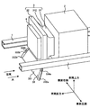
- FIG. 1 shows a state in which an air guide structure according to the present embodiment is provided in a vehicle.
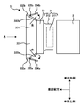
- FIG. 2 shows a state in which the lid of the air guide in the air guide structure according to the present embodiment is open.
- FIG. 3 shows a state in which the lid of the air guide in the air guide structure according to the present embodiment is closed.
- FIG. 1 is a diagram illustrating a state in which an air guide structure 3 according to the present embodiment is provided in a vehicle.
- the air guide structure 3 has a fan 31, a radiator 32, and an air guide 33.
- FIG. 2 is a diagram illustrating a state in which the lid 334 of the air guide 33 in the air guide structure 3 according to the present embodiment is open.
- FIG. 3 is a diagram illustrating a state in which the lid 334 of the air guide 33 in the air guide structure 3 according to the present embodiment is closed. 2 and 3 are views showing the structure as viewed from above the vehicle.
- the vehicle has a side frame 1, an engine 2, an air guide structure 3, and an intercooler 4.
- the side frame 1 is a member extending in the front-rear direction of the vehicle. Two side frames 1 are provided in parallel.
- the engine 2 generates power for driving the vehicle.
- the engine 2 is, for example, a gasoline engine or a diesel engine.
- the engine 2 supplies fuel (for example, gasoline or light oil) and air to burn and generate power and generate exhaust gas.
- the engine 2 is provided behind the fan 31 in the front-rear direction of the vehicle.
- the air guide structure 3 has a function of improving the cooling capacity of the engine 2.
- the air guide structure 3 is provided in front of the engine 2 in the front-rear direction of the vehicle. The details of the air guide structure 3 will be described later.
- the intercooler 4 is a device for cooling air whose temperature has increased by being compressed by a supercharger (for example, a turbocharger).
- the supercharger is a device that uses the exhaust gas of the engine 2 to increase the pressure, that is, the density of the air supplied to the engine 2.
- the intercooler 4 is provided in front of the radiator 32.
- the upper end of the intercooler 4 is located below the upper end of the radiator 32 in the height direction of the vehicle.
- the intercooler 4 has an air inlet through which cooling air (for example, traveling wind or air flowing by the fan 31) flows into a front surface of the vehicle in the front-rear direction, and supplies the cooling air to a rear surface of the intercooler 4. It has an outflow air outlet.
- the intercooler 4 heat-exchanges air flowing from the front in the front-rear direction of the vehicle (for example, traveling air or air flowing by the fan 31) with air having a higher temperature flowing from the supercharger. Cools the heated air that flows from the feeder.
- the air flowing out of the intercooler 4 deprives the heat of the air flowing from the supercharger in the intercooler 4, so that the temperature rises as compared with the air flowing into the intercooler 4.
- the fan 31 is a blower for flowing air.
- the fan 31 has a fan body 311 and a fan cover 312.
- the fan body 311 has, for example, a rotating shaft and a plurality of blades provided on the outer surface of the rotating shaft, and the air flows by rotating the rotating shaft and moving the plurality of blades.
- the fan body 311 is housed inside the fan cover 312.
- the fan cover 312 is a cover that houses the fan body 311 inside.
- the fan cover 312 has a substantially cylindrical shape, for example, and is provided outside the fan main body 311.
- the fan cover 312 has an inflow port into which air flows in a front surface of the vehicle in the front-rear direction, and an outflow port through which the air flows out in a rear surface.
- a front end of the fan cover 312 in the front-rear direction of the vehicle is connected to, for example, a rear end of the radiator 32.
- the fan 31 is provided in front of the engine 2. Specifically, the fan 31 is provided behind the radiator 32 in the front-rear direction of the vehicle and in front of the engine 2.
- the fan body 311 is connected to the engine 2 via a shaft, and has a structure in which the fan body 311 is driven to rotate by receiving power from the engine 2, but may be an electric fan.
- the fan 31 allows the air to flow from the front to the rear in the front-rear direction of the vehicle when the fan body 311 operates.
- the fan 31 allows air to flow from the front to the rear of the radiator 32 and the intercooler 4, for example.
- the radiator 32 cools the heat transfer medium that cools the engine 2.
- the heat transfer medium is cooling water for cooling the engine 2.
- the heat transfer medium is circulating between the radiator 32 and the engine 2.
- the radiator 32 cools the heat transfer medium heated by flowing through the engine 2.
- the radiator 32 is provided in front of the engine 2 and the fan 31.
- the radiator 32 has an air inlet through which cooling air (for example, traveling wind or air flowing by the fan 31) flows into a front surface of the vehicle in the front-rear direction, and causes the cooling air to flow out to a rear surface of the radiator 32. It has an air outlet.
- the radiator 32 is heated by exchanging heat between air flowing in from the front in the front-rear direction of the vehicle (for example, traveling wind or air flowing by the fan 31) and a heated heat transfer medium flowing out of the engine 2. Cool the heat transfer medium.
- the heat transfer medium cooled by the radiator 32 flows into the engine 2.
- the temperature of the air flowing out of the radiator 32 is higher than that of the air flowing into the radiator 32 by removing heat of the heat transfer medium flowing out of the engine 2 in the radiator 32.
- the air guide 33 is provided so as to extend downward from the lower end of the radiator 32, and is a guide member for flowing air, for example, a running wind at a lower part of the vehicle, to the radiator 32.
- the traveling wind flowing from the front to the rear in the front-rear direction of the vehicle flows toward the radiator 32 along the air guide 33 and flows forward of the radiator 32.
- the air guide 33 has a bottom plate 331, a plurality of side plates 332, a plurality of openings 333, a plurality of lids 334, and a plurality of hinges 335.
- the bottom plate portion 331 has, for example, a flat plate shape.
- the bottom plate 331 extends downward from the lower end of the radiator 32.
- the bottom plate 331 is provided at a predetermined angle with respect to the height direction of the vehicle such that, for example, the lower end of the bottom plate 331 is located forward of the upper end of the bottom plate 331 in the front-rear direction of the vehicle.
- the upper end of the bottom plate 331 is fixed to the lower end of the radiator 32.
- the upper end of the bottom plate 331 may be fixed to the lower end of the radiator 32 via a bracket (not shown).
- the upper end of the bottom plate portion 331 is fixed to, for example, the front surface and the lower end of the radiator 32.
- the plurality of side plate portions 332 are provided at both ends of the bottom plate portion 331 in the vehicle width direction of the vehicle.
- the plurality of side plate portions 332 are provided on the bottom plate portion 331, for example, orthogonal to the bottom plate portion 331.
- a left side plate portion 332a and a right side plate portion 332b are provided as the plurality of side plate portions 332, a left side plate portion 332a and a right side plate portion 332b are provided.
- the left side plate portion 332a is a side plate portion provided at the left end of the bottom plate portion 331 in the vehicle width direction of the vehicle.
- the left side plate portion 332a is provided on the bottom plate portion 331, for example, orthogonal to the bottom plate portion 331.
- the right side plate portion 332b is a side plate portion provided at the right end of the bottom plate portion 331 in the vehicle width direction.
- the right side plate portion 332b is provided on the bottom plate portion 331, for example, orthogonal to the bottom plate portion 331.
- the plurality of openings 333 are openings formed in the plurality of side plate portions 332, respectively.
- the opening 333 allows the liquid received by the front surface of the air guide 33 to flow from the inside of the air guide 33 to the outside of the air guide 33.
- the liquid is, for example, water.
- a left opening 333a and a right opening 333b are provided as the plurality of openings 333.
- the left opening 333a is an opening formed in the left side plate 332a.
- the right opening 333b is an opening formed in the right plate 332b.
- the lid 334 is displaceable with respect to the side plate 332 and shields at least a part of the opening 333.
- a left lid 334a and a right lid 334b are provided as the plurality of lids 334.
- the left lid part 334a is displaceable with respect to the left side plate part 332a, and shields at least a part of the left opening part 333a.
- the right lid 334b is displaceable with respect to the right plate 332b, and covers at least a part of the right opening 333b. The operation of the cover 334 will be described later.
- the hinge 335 is a member that rotatably supports the lid 334 with respect to the side plate 332.
- the hinge part 335 has, for example, two movable pieces and one rotation axis.
- One movable piece of the hinge part 335 is fixed, for example, near the front end of the lid part 334 in the front-rear direction of the vehicle, and the other movable piece of the hinge part 335 is, for example, an opening part 333 of the side plate part 332. Is fixed near the front edge of the vehicle in the front-rear direction.
- the rotation axis of the hinge 335 has, for example, a columnar shape and extends in the height direction of the vehicle.
- the lid 334 is connected to the front end of the vehicle in the front-rear direction of the opening 333 of the side plate portion 332 via the hinge 335 in the front-rear direction of the vehicle.
- the rotation of the rear end of the lid portion 334 is performed about the rotation axis of the hinge portion 335 provided near the front end in the above.
- a left hinge part 335a and a right hinge part 335b are provided as the plurality of hinge parts 335.
- the left hinge 335a is a member that rotatably supports the left lid 334a with respect to the left plate 332a.
- the right hinge 335b is a member that rotatably supports the right lid 334b with respect to the right plate 332b.
- the first position is a position where the cover 334 is positioned such that the rear end of the cover 334 in the front-rear direction of the vehicle does not contact the outer surface of the side plate 332.
- the lid 334 is not parallel to, for example, the side plate 332.
- the second position is a position where the cover 334 is positioned such that the rear end of the cover 334 in the front-rear direction of the vehicle is in contact with the outer surface of the side plate 332.
- the lid 334 is, for example, parallel to the side plate 332.
- the air guide 33 when the air guide 33 does not receive liquid, the air flows from the front to the rear in the front-rear direction of the vehicle inside the air guide 33 by the operation of the fan 31 when the air guide 33 does not receive liquid.
- the pressure inside the air guide 33 is smaller than the pressure outside the air guide 33, so that the air is prevented from flowing out from the inside of the air guide 33 to the outside of the air guide 33 through the opening 333. It is located at position 2.
- the lid portion 334 is, for example, in a first position where the opening portion 333 is opened by being pushed from the inside of the air guide 33 to the outside of the air guide 33 by a liquid when the vehicle is submerged. (FIG. 2). Further, after the flooding of the vehicle, the lid 334 is located at the second position where the opening 333 is closed by the air flowing from the front to the rear in the front-rear direction of the vehicle by the operation of the fan 31 ( (Fig. 3).
- the air guide structure 3 causes the liquid to flow out of the opening 333, thereby reducing the force with which the air guide 33 is pushed by the liquid, and thus making the air guide 33 hard to break.
- the air guide 33 does not receive the liquid, for example, when the lid 334 is open after the vehicle is submerged, air flowing from the front to the rear in the front-rear direction of the vehicle flows through the air guide 33 through the opening 333. Out of the air guide 33 from the inside of the air guide. For this reason, when the lid 334 is in an open state, the air flows out from the inside of the air guide 33 to the outside of the air guide 33 through the opening 333, so that the air flows from the air guide 33 to the radiator 32. Since the flowing air decreases, the cooling performance of the radiator 32 decreases.
- the air guide structure 3 prevents the air from flowing from the inside of the air guide 33 to the outside of the air guide 33 through the opening 333 when the opening 333 is closed by the lid 334. Can be prevented.
- the air guide structure 3 can prevent the cooling performance of the radiator 32 from being reduced.
- the air guide structure 3 includes a radiator 32 of a vehicle, and an air guide 33 that extends downward from a lower end of the radiator 32 and that flows air to the radiator 32.
- the air guide 33 has an opening 333 that allows the liquid received by the front surface of the air guide 33 to flow from inside the air guide 33 to outside the air guide 33.
- the air guide structure 3 has the air guide 33 provided with the opening 333 that allows the liquid received by the front surface of the air guide 33 to flow from the inside of the air guide 33 to the outside of the air guide 33. . Therefore, the air guide structure 3 causes the liquid received by the front surface of the air guide 33 to flow out from the inside of the air guide 33 to the outside of the air guide 33 through the opening 333. As a result, the air guide structure 3 can reduce the force with which the air guide 33 is pushed rearward by the liquid received on the front surface of the air guide 33, so that the air guide 33 can be hardly broken.
- the present invention has been described using the embodiment, but the technical scope of the present invention is not limited to the scope described in the above embodiment, and various modifications and changes are possible within the scope of the gist. is there.
- the specific embodiment of the distribution / integration of the apparatus is not limited to the above-described embodiment, and all or a part of the apparatus may be functionally or physically distributed / integrated in arbitrary units. Can be.
- new embodiments that are generated by arbitrary combinations of the plurality of embodiments are also included in the embodiments of the present invention. The effect of the new embodiment caused by the combination has the effect of the original embodiment.
- the present invention has an effect that the air guide of the radiator hardly breaks when receiving a liquid, and is useful for an air guide structure of a vehicle and the like.
Landscapes
- Engineering & Computer Science (AREA)
- Chemical & Material Sciences (AREA)
- Combustion & Propulsion (AREA)
- Transportation (AREA)
- Mechanical Engineering (AREA)
- Cooling, Air Intake And Gas Exhaust, And Fuel Tank Arrangements In Propulsion Units (AREA)
Abstract
This air guide structure 3 has a vehicle radiator 32, and an air guide 33 which is disposed extending downwards from the bottom edge of the radiator 32 and which guides air into the radiator 32. The air guide 33 has openings 333, 333a, 333b for draining liquid received by the front surface of the air guide 33 from inside of the air guide 33 to outside of the air guide 33.
Description
本開示は、車両のエアガイド構造に関する。
The present disclosure relates to an air guide structure for a vehicle.
従来、車両には、ラジエータのエアガイドが設けられている。特許文献1には、車両に、ラジエータ前面側で車体フレームを横断する下り傾斜のガイド板が設けられている構造が開示されている。
Conventionally, vehicles are provided with a radiator air guide. Patent Literature 1 discloses a structure in which a vehicle is provided with a downwardly inclined guide plate that crosses a vehicle body frame on the front side of a radiator.
特許文献1に示すように、ラジエータの下端から下方に延在するエアガイドを有する車両において、エアガイドの前面に液体を受ける場合(例えば、車両が冠水走行する場合)、エアガイドは液体によって押される力を受けるため、エアガイドが壊れてしまうという問題が生じていた。
As shown in Patent Document 1, in a vehicle having an air guide extending downward from a lower end of a radiator, when receiving liquid on the front surface of the air guide (for example, when the vehicle is submerged), the air guide is pressed by the liquid. There is a problem that the air guide is broken due to the force that is applied.
そこで、本開示はこれらの点に鑑みてなされたものであり、ラジエータのエアガイドが液体を受けた場合に壊れづらいエアガイド構造を提供することを目的とする。
Accordingly, the present disclosure has been made in view of these points, and an object of the present disclosure is to provide an air guide structure that is not easily broken when an air guide of a radiator receives a liquid.
本開示の第1の態様においては、車両のラジエータと、前記ラジエータの下端から下方に向かって延伸して設けられており、かつ前記ラジエータに空気を流すエアガイドと、を有し、前記エアガイドは、前記エアガイドの前面が受ける液体を前記エアガイドの内側から前記エアガイドの外側に流出させる開口部を有することを特徴とするエアガイド構造を提供する。
In a first aspect of the present disclosure, the air guide includes: a radiator of a vehicle; and an air guide that extends downward from a lower end of the radiator and that flows air to the radiator. Provides an air guide structure having an opening through which liquid received by a front surface of the air guide flows out of the air guide to the outside of the air guide.
また、前記ラジエータの後方に設けられており、かつ前記ラジエータの前方から後方に向かって空気を流すファンをさらに有し、前記エアガイドは、前記エアガイドの前面に前記液体を受ける場合には、前記液体によって前記エアガイドの内側から前記エアガイドの外側に向かって押されることで前記開口部が開かれた第1の位置に位置し、前記エアガイドの前面に前記液体を受けない場合には、前記ファンの作動によって前記車両の前後方向における前方から後方に向かって空気が流れることで前記開口部が閉じられた第2の位置に移動する蓋部をさらに有していてもよい。
Further, a fan is provided behind the radiator, and further has a fan for flowing air from the front to the rear of the radiator, wherein the air guide receives the liquid on a front surface of the air guide. When the liquid is pushed toward the outside of the air guide from the inside of the air guide by the liquid, the opening is located at the first position opened, and the liquid is not received on the front surface of the air guide. The air conditioner may further include a lid that moves to a second position in which the opening is closed when air flows from the front to the rear in the front-rear direction of the vehicle by the operation of the fan.
また、前記蓋部は、前記エアガイドの前面に前記液体を受ける場合に、前記開口部を通して前記エアガイドの内側から前記エアガイドの外側に向かって前記液体を流出させる前記第1の位置に位置していてもよい。また、前記蓋部は、前記エアガイドが前記液体を受けない場合に、前記ファンの作動によって前記エアガイドの内側を前記車両の前後方向における前方から後方に向かって空気が流れて前記エアガイドの内側の圧力が前記エアガイドの外側の圧力よりも小さくなることで、前記開口部を通して前記エアガイドの内側から前記エアガイドの外側に向かって前記空気を流出させるのを抑制する前記第2の位置に位置していてもよい。
The lid is located at the first position where the liquid flows out from the inside of the air guide toward the outside of the air guide through the opening when receiving the liquid on the front surface of the air guide. It may be. Further, when the air guide does not receive the liquid, the air flows from the front to the rear in the front-rear direction of the vehicle inside the air guide by the operation of the fan when the air guide does not receive the liquid. The second position in which the inside pressure is smaller than the outside pressure of the air guide, so that the air is prevented from flowing out from the inside of the air guide toward the outside of the air guide through the opening. May be located.
また、前記蓋部は、前記車両の冠水走行時には、前記液体によって前記エアガイドの内側から前記エアガイドの外側に向かって押されることで前記開口部が開かれた前記第1の位置に位置し、前記車両の冠水走行後には、前記ファンの作動によって前記車両の前後方向における前方から後方に向かって空気が流れることで前記開口部が閉じられた前記第2の位置に位置していてもよい。
The lid is located at the first position where the opening is opened by being pushed by the liquid from the inside of the air guide to the outside of the air guide when the vehicle is being flooded. After the vehicle is submerged, the air may flow from the front to the rear in the front-rear direction of the vehicle by the operation of the fan, and the opening may be closed at the second position. .
また、前記エアガイドは、前記ラジエータの下端から下方に向かって延在する底板部と、前記底板部の前記車両の車幅方向における両端に前記底板部と直交して設けられている複数の側板部と、前記複数の側板部にそれぞれ形成されている前記開口部と、前記側板部に対して変位可能であり、前記開口部の少なくとも一部を遮蔽する前記蓋部と、を有していてもよい。
Further, the air guide includes a bottom plate portion extending downward from a lower end of the radiator, and a plurality of side plates provided at both ends of the bottom plate portion in the vehicle width direction of the vehicle so as to be orthogonal to the bottom plate portion. Part, the opening formed in each of the plurality of side plate parts, and the lid part displaceable with respect to the side plate part and shielding at least a part of the opening part. Is also good.
また、前記エアガイドは、前記ラジエータの下端から下方に向かって延在する底板部と、前記底板部の前記車両の車幅方向における両端に前記底板部と直交して設けられている複数の側板部と、をさらに有し、 前記蓋部は、前記第1の位置にあるときは、前記側板部とは平行ではなくてもよい。
Further, the air guide includes a bottom plate portion extending downward from a lower end of the radiator, and a plurality of side plates provided at both ends of the bottom plate portion in the vehicle width direction of the vehicle so as to be orthogonal to the bottom plate portion. And the lid portion may not be parallel to the side plate portion when in the first position.
また、前記蓋部は、前記第1の位置にあるとき、前記蓋部の前記車両の前後方向における後端が、前記側板部の外側面と接しなくてもよい。
When the lid is at the first position, the rear end of the lid in the front-rear direction of the vehicle may not be in contact with the outer surface of the side plate.
本開示によれば、エアガイド構造において、ラジエータのエアガイドが液体を受けた場合に壊れづらくなるという効果を奏する。
According to the present disclosure, in the air guide structure, there is an effect that the air guide of the radiator is hardly broken when receiving the liquid.
<本実施形態>
[エアガイド構造3の周辺構成]
図1は、本実施形態に係るエアガイド構造3が車両に設けられている状態を示す図である。エアガイド構造3は、ファン31、ラジエータ32、及びエアガイド33を有する。図2は、本実施形態に係るエアガイド構造3におけるエアガイド33の蓋部334が開いている状態を示す図である。図3は、本実施形態に係るエアガイド構造3におけるエアガイド33の蓋部334が閉じている状態を示す図である。なお、図2及び図3は、車両の上方から見た構造を示す図である。 <The present embodiment>
[Peripheral Configuration of Air Guide Structure 3]
FIG. 1 is a diagram illustrating a state in which anair guide structure 3 according to the present embodiment is provided in a vehicle. The air guide structure 3 has a fan 31, a radiator 32, and an air guide 33. FIG. 2 is a diagram illustrating a state in which the lid 334 of the air guide 33 in the air guide structure 3 according to the present embodiment is open. FIG. 3 is a diagram illustrating a state in which the lid 334 of the air guide 33 in the air guide structure 3 according to the present embodiment is closed. 2 and 3 are views showing the structure as viewed from above the vehicle.
[エアガイド構造3の周辺構成]
図1は、本実施形態に係るエアガイド構造3が車両に設けられている状態を示す図である。エアガイド構造3は、ファン31、ラジエータ32、及びエアガイド33を有する。図2は、本実施形態に係るエアガイド構造3におけるエアガイド33の蓋部334が開いている状態を示す図である。図3は、本実施形態に係るエアガイド構造3におけるエアガイド33の蓋部334が閉じている状態を示す図である。なお、図2及び図3は、車両の上方から見た構造を示す図である。 <The present embodiment>
[Peripheral Configuration of Air Guide Structure 3]
FIG. 1 is a diagram illustrating a state in which an
車両は、サイドフレーム1、エンジン2、エアガイド構造3、及びインタークーラ4を有する。サイドフレーム1は、車両の前後方向において延伸している部材である。2本のサイドフレーム1が平行に設けられている。
The vehicle has a side frame 1, an engine 2, an air guide structure 3, and an intercooler 4. The side frame 1 is a member extending in the front-rear direction of the vehicle. Two side frames 1 are provided in parallel.
エンジン2は、車両を駆動するための動力を発生する。エンジン2は、例えばガソリンエンジン又はディーゼルエンジンである。エンジン2は、燃料(例えば、ガソリン又は軽油)及び空気を供給して燃焼させることで動力を発生すると共に排気ガスを生じる。エンジン2は、車両の前後方向において、ファン31の後方に設けられている。
The engine 2 generates power for driving the vehicle. The engine 2 is, for example, a gasoline engine or a diesel engine. The engine 2 supplies fuel (for example, gasoline or light oil) and air to burn and generate power and generate exhaust gas. The engine 2 is provided behind the fan 31 in the front-rear direction of the vehicle.
エアガイド構造3は、エンジン2の冷却能力を向上させる機能を有する。エアガイド構造3は、車両の前後方向において、エンジン2の前方に設けられている。エアガイド構造3の詳細は後述する。
The air guide structure 3 has a function of improving the cooling capacity of the engine 2. The air guide structure 3 is provided in front of the engine 2 in the front-rear direction of the vehicle. The details of the air guide structure 3 will be described later.
インタークーラ4は、過給機(例えばターボチャージャ)で圧縮することにより温度が上昇した空気を冷却するための装置である。過給機は、エンジン2の排気ガスを利用してエンジン2に供給する空気の圧力、すなわち密度を高める装置である。
The intercooler 4 is a device for cooling air whose temperature has increased by being compressed by a supercharger (for example, a turbocharger). The supercharger is a device that uses the exhaust gas of the engine 2 to increase the pressure, that is, the density of the air supplied to the engine 2.
インタークーラ4は、ラジエータ32の前方に設けられている。インタークーラ4の上端は、ラジエータ32の上端よりも車両の高さ方向において下方に位置する。
The intercooler 4 is provided in front of the radiator 32. The upper end of the intercooler 4 is located below the upper end of the radiator 32 in the height direction of the vehicle.
インタークーラ4は、車両の前後方向における前面に冷却用の空気(例えば、走行風又はファン31によって流れる空気)を流入させる空気流入口を有し、インタークーラ4の後面に当該冷却用の空気を流出させる空気流出口を有する。インタークーラ4は、車両の前後方向における前方から流入した空気(例えば、走行風又はファン31によって流れる空気)と、過給機から流れてきた温度が上昇した空気とを熱交換することで、過給機から流れてきた温度が上昇した空気を冷却する。インタークーラ4から流出する空気は、インタークーラ4において過給機から流れてきた空気の熱を奪うことで、インタークーラ4に流入する空気に比べて、温度が上昇する。
The intercooler 4 has an air inlet through which cooling air (for example, traveling wind or air flowing by the fan 31) flows into a front surface of the vehicle in the front-rear direction, and supplies the cooling air to a rear surface of the intercooler 4. It has an outflow air outlet. The intercooler 4 heat-exchanges air flowing from the front in the front-rear direction of the vehicle (for example, traveling air or air flowing by the fan 31) with air having a higher temperature flowing from the supercharger. Cools the heated air that flows from the feeder. The air flowing out of the intercooler 4 deprives the heat of the air flowing from the supercharger in the intercooler 4, so that the temperature rises as compared with the air flowing into the intercooler 4.
[エアガイド構造3]
ファン31は、空気を流す送風機である。ファン31は、ファン本体311、及びファンカバー312を有している。ファン本体311は、例えば、回転軸と回転軸の外側面に設けられている複数の羽根を有し、回転軸が回転して複数の羽根が移動することで空気を流す。ファン本体311は、ファンカバー312の内側に収容されている。ファンカバー312は、ファン本体311を内側に収容するカバーである。ファンカバー312は、例えば略円筒形状であり、ファン本体311の外側に設けられている。 [Air guide structure 3]
Thefan 31 is a blower for flowing air. The fan 31 has a fan body 311 and a fan cover 312. The fan body 311 has, for example, a rotating shaft and a plurality of blades provided on the outer surface of the rotating shaft, and the air flows by rotating the rotating shaft and moving the plurality of blades. The fan body 311 is housed inside the fan cover 312. The fan cover 312 is a cover that houses the fan body 311 inside. The fan cover 312 has a substantially cylindrical shape, for example, and is provided outside the fan main body 311.
ファン31は、空気を流す送風機である。ファン31は、ファン本体311、及びファンカバー312を有している。ファン本体311は、例えば、回転軸と回転軸の外側面に設けられている複数の羽根を有し、回転軸が回転して複数の羽根が移動することで空気を流す。ファン本体311は、ファンカバー312の内側に収容されている。ファンカバー312は、ファン本体311を内側に収容するカバーである。ファンカバー312は、例えば略円筒形状であり、ファン本体311の外側に設けられている。 [Air guide structure 3]
The
ファンカバー312は、車両の前後方向における前面に空気が流入する流入口を有し、後面に当該空気が流出する流出口を有する。ファンカバー312の車両の前後方向における前端は、例えばラジエータ32の後端に接続されている。
The fan cover 312 has an inflow port into which air flows in a front surface of the vehicle in the front-rear direction, and an outflow port through which the air flows out in a rear surface. A front end of the fan cover 312 in the front-rear direction of the vehicle is connected to, for example, a rear end of the radiator 32.
ファン31は、エンジン2の前方に設けられている。具体的には、ファン31は、車両の前後方向におけるラジエータ32の後方、かつエンジン2の前方に設けられている。ファン本体311は、エンジン2に軸を介して連結されており、エンジン2から動力を受けて回転駆動される構造であるが、電動ファンであってもよい。ファン31は、ファン本体311が作動することで、車両の前後方向における前方から後方に向かって空気を流す。具体的には、ファン31は、例えばラジエータ32及びインタークーラ4の前方から後方に向かって空気を流す。
The fan 31 is provided in front of the engine 2. Specifically, the fan 31 is provided behind the radiator 32 in the front-rear direction of the vehicle and in front of the engine 2. The fan body 311 is connected to the engine 2 via a shaft, and has a structure in which the fan body 311 is driven to rotate by receiving power from the engine 2, but may be an electric fan. The fan 31 allows the air to flow from the front to the rear in the front-rear direction of the vehicle when the fan body 311 operates. Specifically, the fan 31 allows air to flow from the front to the rear of the radiator 32 and the intercooler 4, for example.
ラジエータ32は、エンジン2を冷却する熱搬送媒体を冷却する。熱搬送媒体は、エンジン2を冷却する冷却水である。熱搬送媒体は、ラジエータ32とエンジン2との間で循環している。ラジエータ32は、エンジン2を流れることで加熱された熱搬送媒体を冷却する。
The radiator 32 cools the heat transfer medium that cools the engine 2. The heat transfer medium is cooling water for cooling the engine 2. The heat transfer medium is circulating between the radiator 32 and the engine 2. The radiator 32 cools the heat transfer medium heated by flowing through the engine 2.
ラジエータ32は、エンジン2及びファン31の前方に設けられている。ラジエータ32は、車両の前後方向における前面に冷却用の空気(例えば、走行風又はファン31よって流れる空気)を流入させる空気流入口を有し、ラジエータ32の後面に当該冷却用の空気を流出させる空気流出口を有する。ラジエータ32は、車両の前後方向における前方から流入した空気(例えば、走行風又はファン31によって流れる空気)と、エンジン2から流出した加熱された熱搬送媒体とを熱交換することで、加熱された熱搬送媒体を冷却する。ラジエータ32で冷却された熱搬送媒体は、エンジン2に流入する。
The radiator 32 is provided in front of the engine 2 and the fan 31. The radiator 32 has an air inlet through which cooling air (for example, traveling wind or air flowing by the fan 31) flows into a front surface of the vehicle in the front-rear direction, and causes the cooling air to flow out to a rear surface of the radiator 32. It has an air outlet. The radiator 32 is heated by exchanging heat between air flowing in from the front in the front-rear direction of the vehicle (for example, traveling wind or air flowing by the fan 31) and a heated heat transfer medium flowing out of the engine 2. Cool the heat transfer medium. The heat transfer medium cooled by the radiator 32 flows into the engine 2.
また、ラジエータ32から流出する空気は、ラジエータ32においてエンジン2から流出した熱搬送媒体の熱を奪うことで、ラジエータ32に流入する空気に比べて、温度が上昇する。
(4) The temperature of the air flowing out of the radiator 32 is higher than that of the air flowing into the radiator 32 by removing heat of the heat transfer medium flowing out of the engine 2 in the radiator 32.
エアガイド33は、ラジエータ32の下端から下方に向かって延伸して設けられており、ラジエータ32に空気、例えば車両下部の走行風を流すためのガイド部材である。車両の前後方向における前方から後方に流れる走行風は、エアガイド33に沿ってラジエータ32に向かい、ラジエータ32の前方に流れる。
The air guide 33 is provided so as to extend downward from the lower end of the radiator 32, and is a guide member for flowing air, for example, a running wind at a lower part of the vehicle, to the radiator 32. The traveling wind flowing from the front to the rear in the front-rear direction of the vehicle flows toward the radiator 32 along the air guide 33 and flows forward of the radiator 32.
エアガイド33は、底板部331、複数の側板部332、複数の開口部333、複数の蓋部334、及び複数のヒンジ部335を有する。
The air guide 33 has a bottom plate 331, a plurality of side plates 332, a plurality of openings 333, a plurality of lids 334, and a plurality of hinges 335.
底板部331は、例えば平板形状である。底板部331は、ラジエータ32の下端から下方に向かって延在する。底板部331は、例えば底板部331の下端が底板部331の上端よりも車両の前後方向において前方に位置するように、車両の高さ方向と所定の角度で傾斜して設けられている。
The bottom plate portion 331 has, for example, a flat plate shape. The bottom plate 331 extends downward from the lower end of the radiator 32. The bottom plate 331 is provided at a predetermined angle with respect to the height direction of the vehicle such that, for example, the lower end of the bottom plate 331 is located forward of the upper end of the bottom plate 331 in the front-rear direction of the vehicle.
底板部331の上端は、ラジエータ32の下端に固定されている。または、底板部331の上端は、図示しないブラケットを介してラジエータ32の下端に固定されていてもよい。具体的には、底板部331の上端は、例えばラジエータ32の前面、かつ下端に固定されている。
上端 The upper end of the bottom plate 331 is fixed to the lower end of the radiator 32. Alternatively, the upper end of the bottom plate 331 may be fixed to the lower end of the radiator 32 via a bracket (not shown). Specifically, the upper end of the bottom plate portion 331 is fixed to, for example, the front surface and the lower end of the radiator 32.
複数の側板部332は、底板部331の車両の車幅方向における両端に設けられている。複数の側板部332は、例えば底板部331と直交して底板部331に設けられている。複数の側板部332として、左側板部332a、及び右側板部332bが設けられている。左側板部332aは、底板部331の車両の車幅方向における左端に設けられている側板部である。左側板部332aは、例えば底板部331と直交して底板部331に設けられている。
The plurality of side plate portions 332 are provided at both ends of the bottom plate portion 331 in the vehicle width direction of the vehicle. The plurality of side plate portions 332 are provided on the bottom plate portion 331, for example, orthogonal to the bottom plate portion 331. As the plurality of side plate portions 332, a left side plate portion 332a and a right side plate portion 332b are provided. The left side plate portion 332a is a side plate portion provided at the left end of the bottom plate portion 331 in the vehicle width direction of the vehicle. The left side plate portion 332a is provided on the bottom plate portion 331, for example, orthogonal to the bottom plate portion 331.
右側板部332bは、底板部331の車両の車幅方向における右端に設けられている側板部である。右側板部332bは、例えば底板部331と直交して底板部331に設けられている。
The right side plate portion 332b is a side plate portion provided at the right end of the bottom plate portion 331 in the vehicle width direction. The right side plate portion 332b is provided on the bottom plate portion 331, for example, orthogonal to the bottom plate portion 331.
複数の開口部333は、複数の側板部332にそれぞれ形成されている開口部である。開口部333は、エアガイド33の前面が受ける液体をエアガイド33の内側からエアガイド33の外側に流出させる。液体は、例えば水である。
The plurality of openings 333 are openings formed in the plurality of side plate portions 332, respectively. The opening 333 allows the liquid received by the front surface of the air guide 33 to flow from the inside of the air guide 33 to the outside of the air guide 33. The liquid is, for example, water.
複数の開口部333として、左開口部333a、及び右開口部333bが設けられている。左開口部333aは、左側板部332aに形成されている開口部である。右開口部333bは、右側板部332bに形成されている開口部である。
左 A left opening 333a and a right opening 333b are provided as the plurality of openings 333. The left opening 333a is an opening formed in the left side plate 332a. The right opening 333b is an opening formed in the right plate 332b.
蓋部334は、側板部332に対して変位可能であり、開口部333の少なくとも一部を遮蔽する。複数の蓋部334として、左蓋部334a、及び右蓋部334bが設けられている。左蓋部334aは、左側板部332aに対して変位可能であり、左開口部333aの少なくとも一部を遮蔽する。右蓋部334bは、右側板部332bに対して変位可能であり、右開口部333bの少なくとも一部を遮蔽する。蓋部334の動作については後述する。
The lid 334 is displaceable with respect to the side plate 332 and shields at least a part of the opening 333. As the plurality of lids 334, a left lid 334a and a right lid 334b are provided. The left lid part 334a is displaceable with respect to the left side plate part 332a, and shields at least a part of the left opening part 333a. The right lid 334b is displaceable with respect to the right plate 332b, and covers at least a part of the right opening 333b. The operation of the cover 334 will be described later.
ヒンジ部335は、側板部332に対して蓋部334を回転可能に支持する部材である。ヒンジ部335は、例えば2枚の可動片と1本の回転軸を有する。ヒンジ部335の一方の可動片は、例えば蓋部334の車両の前後方向における前方側の端部付近に固定されており、ヒンジ部335の他方の可動片は、例えば側板部332の開口部333の車両の前後方向における前縁付近に固定されている。ヒンジ部335の回転軸は、例えば円柱形状であり、車両の高さ方向において延伸している。
The hinge 335 is a member that rotatably supports the lid 334 with respect to the side plate 332. The hinge part 335 has, for example, two movable pieces and one rotation axis. One movable piece of the hinge part 335 is fixed, for example, near the front end of the lid part 334 in the front-rear direction of the vehicle, and the other movable piece of the hinge part 335 is, for example, an opening part 333 of the side plate part 332. Is fixed near the front edge of the vehicle in the front-rear direction. The rotation axis of the hinge 335 has, for example, a columnar shape and extends in the height direction of the vehicle.
蓋部334は、車両の前後方向における前端付近がヒンジ部335を介して側板部332の開口部333の車両の前後方向における前縁付近に接続された状態で、蓋部334の車両の前後方向における前端付近に設けられているヒンジ部335の回転軸を軸として、蓋部334の後端が移動することで、回転する。
The lid 334 is connected to the front end of the vehicle in the front-rear direction of the opening 333 of the side plate portion 332 via the hinge 335 in the front-rear direction of the vehicle. The rotation of the rear end of the lid portion 334 is performed about the rotation axis of the hinge portion 335 provided near the front end in the above.
複数のヒンジ部335として、左ヒンジ部335a、及び右ヒンジ部335bが設けられている。左ヒンジ部335aは、左側板部332aに対して左蓋部334aを回転可能に支持する部材である。右ヒンジ部335bは、右側板部332bに対して右蓋部334bを回転可能に支持する部材である。
左 A left hinge part 335a and a right hinge part 335b are provided as the plurality of hinge parts 335. The left hinge 335a is a member that rotatably supports the left lid 334a with respect to the left plate 332a. The right hinge 335b is a member that rotatably supports the right lid 334b with respect to the right plate 332b.
[蓋部334の動作]
蓋部334は、エアガイド33の前面に液体を受ける場合には、液体によってエアガイド33の内側からエアガイド33の外側に向かって押されることで開口部333が開かれた第1の位置に位置する(図2)。また、蓋部334は、エアガイド33の前面に液体を受けない場合には、ファン31の作動によって車両の前後方向における前方から後方に向かって空気が流れることで開口部333が閉じられた第2の位置に移動する(図3)。 [Operation of Lid 334]
When the liquid is received on the front surface of theair guide 33, the lid 334 is pushed by the liquid from the inside of the air guide 33 toward the outside of the air guide 33, so that the opening 333 is opened at the first position. (Fig. 2). In addition, when the lid 334 does not receive liquid on the front surface of the air guide 33, the air flows from the front to the rear in the front-rear direction of the vehicle by the operation of the fan 31 so that the opening 333 is closed. 2 (FIG. 3).
蓋部334は、エアガイド33の前面に液体を受ける場合には、液体によってエアガイド33の内側からエアガイド33の外側に向かって押されることで開口部333が開かれた第1の位置に位置する(図2)。また、蓋部334は、エアガイド33の前面に液体を受けない場合には、ファン31の作動によって車両の前後方向における前方から後方に向かって空気が流れることで開口部333が閉じられた第2の位置に移動する(図3)。 [Operation of Lid 334]
When the liquid is received on the front surface of the
具体的には、第1の位置は、蓋部334の車両の前後方向における後端が、側板部332の外側面と接しないように、蓋部334が位置しているときの位置である。このとき、蓋部334は、例えば側板部332と平行ではない。
Specifically, the first position is a position where the cover 334 is positioned such that the rear end of the cover 334 in the front-rear direction of the vehicle does not contact the outer surface of the side plate 332. At this time, the lid 334 is not parallel to, for example, the side plate 332.
第2の位置は、蓋部334の車両の前後方向における後端が、側板部332の外側面と接するように、蓋部334が位置しているときの位置である。このとき、蓋部334は、例えば側板部332と平行である。
The second position is a position where the cover 334 is positioned such that the rear end of the cover 334 in the front-rear direction of the vehicle is in contact with the outer surface of the side plate 332. At this time, the lid 334 is, for example, parallel to the side plate 332.
具体的には、図2に示すように、蓋部334は、エアガイド33の前面に液体を受ける場合に、開口部333を通してエアガイド33の内側からエアガイド33の外側に向かって液体を流出させる第1の位置に位置する。
Specifically, as shown in FIG. 2, when the lid 334 receives the liquid in front of the air guide 33, the liquid flows out from the inside of the air guide 33 to the outside of the air guide 33 through the opening 333. Located in the first position.
また、図3に示すように、蓋部334は、エアガイド33が液体を受けない場合に、ファン31の作動によってエアガイド33の内側を車両の前後方向における前方から後方に向かって空気が流れてエアガイド33の内側の圧力がエアガイド33の外側の圧力よりも小さくなることで、開口部333を通してエアガイド33の内側からエアガイド33の外側に向かって空気を流出させるのを抑制する第2の位置に位置する。
As shown in FIG. 3, when the air guide 33 does not receive liquid, the air flows from the front to the rear in the front-rear direction of the vehicle inside the air guide 33 by the operation of the fan 31 when the air guide 33 does not receive liquid. The pressure inside the air guide 33 is smaller than the pressure outside the air guide 33, so that the air is prevented from flowing out from the inside of the air guide 33 to the outside of the air guide 33 through the opening 333. It is located at position 2.
より具体的には、蓋部334は、例えば、車両の冠水走行時には、液体によってエアガイド33の内側からエアガイド33の外側に向かって押されることで開口部333が開かれた第1の位置に位置する(図2)。また、蓋部334は、車両の冠水走行後には、ファン31の作動によって車両の前後方向における前方から後方に向かって空気が流れることで開口部333が閉じられた第2の位置に位置する(図3)。
More specifically, the lid portion 334 is, for example, in a first position where the opening portion 333 is opened by being pushed from the inside of the air guide 33 to the outside of the air guide 33 by a liquid when the vehicle is submerged. (FIG. 2). Further, after the flooding of the vehicle, the lid 334 is located at the second position where the opening 333 is closed by the air flowing from the front to the rear in the front-rear direction of the vehicle by the operation of the fan 31 ( (Fig. 3).
このように、エアガイド33が液体を受ける場合、例えば車両が冠水走行する場合に、液体を受けたエアガイド33は、液体によって押されることで、蓋部334が開くので、液体は開口部333を通してエアガイド33の内側からエアガイド33の外側に向かって流れる。よって、エアガイド構造3は、液体を開口部333から流出させることで、液体によってエアガイド33が押される力を減少させるので、エアガイド33を壊れづらくすることができる。
As described above, when the air guide 33 receives the liquid, for example, when the vehicle is submerged, the lid 334 is opened by being pushed by the liquid, so that the liquid flows through the opening 333. Flows from the inside of the air guide 33 to the outside of the air guide 33. Therefore, the air guide structure 3 causes the liquid to flow out of the opening 333, thereby reducing the force with which the air guide 33 is pushed by the liquid, and thus making the air guide 33 hard to break.
そして、エアガイド33が液体を受けない場合、例えば車両が冠水走行後に、蓋部334が開いた状態であると、車両の前後方向における前方から後方に流れる空気は、開口部333を通してエアガイド33の内側からエアガイド33の外側に流出してしまう。このため、蓋部334が開いた状態であると、開口部333を通して空気がエアガイド33の内側からエアガイド33の外側に向かって流出してしまうことで、エアガイド33からラジエータ32に向かって流れる空気が減少してしまうので、ラジエータ32の冷却性能が低下してしまう。
When the air guide 33 does not receive the liquid, for example, when the lid 334 is open after the vehicle is submerged, air flowing from the front to the rear in the front-rear direction of the vehicle flows through the air guide 33 through the opening 333. Out of the air guide 33 from the inside of the air guide. For this reason, when the lid 334 is in an open state, the air flows out from the inside of the air guide 33 to the outside of the air guide 33 through the opening 333, so that the air flows from the air guide 33 to the radiator 32. Since the flowing air decreases, the cooling performance of the radiator 32 decreases.
しかし、前述したように、エアガイド33の前面が液体を受けない場合には、ファン31の作動によって車両の前後方向における前方から後方に向かって空気が流れることで、開口部333が蓋部334で閉じられた状態となる。よって、エアガイド構造3は、開口部333が蓋部334で閉じられた状態になることで、空気が開口部333を通してエアガイド33の内側からエアガイド33の外側に向かって流れてしまうのを防ぐことができる。この結果、エアガイド構造3は、エアガイド33が液体を受けない場合に、ラジエータ32の冷却性能が低下してしまうのを防ぐことができる。
However, as described above, when the front surface of the air guide 33 does not receive the liquid, the air flows from the front to the rear in the front-rear direction of the vehicle by the operation of the fan 31, and the opening 333 is closed by the lid 334. Is closed. Therefore, the air guide structure 3 prevents the air from flowing from the inside of the air guide 33 to the outside of the air guide 33 through the opening 333 when the opening 333 is closed by the lid 334. Can be prevented. As a result, when the air guide 33 does not receive liquid, the air guide structure 3 can prevent the cooling performance of the radiator 32 from being reduced.
[本実施形態に係るエアガイド構造3による効果]
本実施形態に係るエアガイド構造3は、車両のラジエータ32と、ラジエータ32の下端から下方に向かって延伸して設けられており、かつラジエータ32に空気を流すエアガイド33と、を有し、エアガイド33は、エアガイド33の前面が受ける液体をエアガイド33の内側からエアガイド33の外側に流出させる開口部333を有する。 [Effect ofAir Guide Structure 3 According to this Embodiment]
Theair guide structure 3 according to the present embodiment includes a radiator 32 of a vehicle, and an air guide 33 that extends downward from a lower end of the radiator 32 and that flows air to the radiator 32. The air guide 33 has an opening 333 that allows the liquid received by the front surface of the air guide 33 to flow from inside the air guide 33 to outside the air guide 33.
本実施形態に係るエアガイド構造3は、車両のラジエータ32と、ラジエータ32の下端から下方に向かって延伸して設けられており、かつラジエータ32に空気を流すエアガイド33と、を有し、エアガイド33は、エアガイド33の前面が受ける液体をエアガイド33の内側からエアガイド33の外側に流出させる開口部333を有する。 [Effect of
The
本実施形態に係るエアガイド構造3は、このようにエアガイド33の前面が受ける液体をエアガイド33の内側からエアガイド33の外側に流出させる開口部333が設けられているエアガイド33を有する。よって、エアガイド構造3は、エアガイド33の前面が受ける液体を、開口部333を通してエアガイド33の内側からエアガイド33の外側に流出させる。この結果、エアガイド構造3は、エアガイド33の前面が受ける液体によってエアガイド33が後方に押される力を減少させることができるので、エアガイド33を壊れづらくすることができる。
The air guide structure 3 according to the present embodiment has the air guide 33 provided with the opening 333 that allows the liquid received by the front surface of the air guide 33 to flow from the inside of the air guide 33 to the outside of the air guide 33. . Therefore, the air guide structure 3 causes the liquid received by the front surface of the air guide 33 to flow out from the inside of the air guide 33 to the outside of the air guide 33 through the opening 333. As a result, the air guide structure 3 can reduce the force with which the air guide 33 is pushed rearward by the liquid received on the front surface of the air guide 33, so that the air guide 33 can be hardly broken.
以上、本発明を実施の形態を用いて説明したが、本発明の技術的範囲は上記実施の形態に記載の範囲には限定されず、その要旨の範囲内で種々の変形及び変更が可能である。例えば、装置の分散・統合の具体的な実施の形態は、以上の実施の形態に限られず、その全部又は一部について、任意の単位で機能的又は物理的に分散・統合して構成することができる。また、複数の実施の形態の任意の組み合わせによって生じる新たな実施の形態も、本発明の実施の形態に含まれる。組み合わせによって生じる新たな実施の形態の効果は、もとの実施の形態の効果を合わせ持つ。
As described above, the present invention has been described using the embodiment, but the technical scope of the present invention is not limited to the scope described in the above embodiment, and various modifications and changes are possible within the scope of the gist. is there. For example, the specific embodiment of the distribution / integration of the apparatus is not limited to the above-described embodiment, and all or a part of the apparatus may be functionally or physically distributed / integrated in arbitrary units. Can be. Further, new embodiments that are generated by arbitrary combinations of the plurality of embodiments are also included in the embodiments of the present invention. The effect of the new embodiment caused by the combination has the effect of the original embodiment.
本出願は、2018年9月13日付で出願された日本国特許出願(特願2018-171773)に基づくものであり、その内容はここに参照として取り込まれる。
This application is based on a Japanese patent application filed on September 13, 2018 (Japanese Patent Application No. 2018-171773), the contents of which are incorporated herein by reference.
本発明は、ラジエータのエアガイドが液体を受けた場合に壊れづらくなるという効果を有し、車両のエアガイド構造等に有用である。
The present invention has an effect that the air guide of the radiator hardly breaks when receiving a liquid, and is useful for an air guide structure of a vehicle and the like.
1・・・サイドフレーム
2・・・エンジン
3・・・エアガイド構造
31・・・ファン
311・・・ファン本体
312・・・ファンカバー
32・・・ラジエータ
33・・・エアガイド
331・・・底板部
332、332a、332b・・・側板部
333、333a、333b・・・開口部
334、334a、334b・・・蓋部
335、335a、335b・・・ヒンジ部
4・・・インタークーラ DESCRIPTION OF SYMBOLS 1 ...Side frame 2 ... Engine 3 ... Air guide structure 31 ... Fan 311 ... Fan main body 312 ... Fan cover 32 ... Radiator 33 ... Air guide 331 ... Bottom plate 332, 332a, 332b ... side plate 333, 333a, 333b ... opening 334, 334a, 334b ... lid 335, 335a, 335b ... hinge 4 ... intercooler
2・・・エンジン
3・・・エアガイド構造
31・・・ファン
311・・・ファン本体
312・・・ファンカバー
32・・・ラジエータ
33・・・エアガイド
331・・・底板部
332、332a、332b・・・側板部
333、333a、333b・・・開口部
334、334a、334b・・・蓋部
335、335a、335b・・・ヒンジ部
4・・・インタークーラ DESCRIPTION OF SYMBOLS 1 ...
Claims (8)
- 車両のラジエータと、
前記ラジエータの下端から下方に向かって延伸して設けられており、かつ前記ラジエータに空気を流すエアガイドと、
を有し、
前記エアガイドは、前記エアガイドの前面が受ける液体を前記エアガイドの内側から前記エアガイドの外側に流出させる開口部を有することを特徴とするエアガイド構造。 A radiator for the vehicle,
An air guide that is provided to extend downward from a lower end of the radiator, and that flows air to the radiator;
Has,
The air guide structure, wherein the air guide has an opening for allowing liquid received by a front surface of the air guide to flow from inside the air guide to outside the air guide. - 前記ラジエータの後方に設けられており、かつ前記ラジエータの前方から後方に向かって空気を流すファンをさらに有し、
前記エアガイドは蓋部をさらに有し、
前記蓋部は、
前記エアガイドの前面に前記液体を受ける場合には、前記液体によって前記エアガイドの内側から前記エアガイドの外側に向かって押されることで前記開口部が開かれた第1の位置に位置し、
前記エアガイドの前面に前記液体を受けない場合には、前記ファンの作動によって前記車両の前後方向における前方から後方に向かって空気が流れることで前記開口部が閉じられた第2の位置に移動することを特徴とする、
請求項1に記載のエアガイド構造。 Further provided is a fan provided behind the radiator, and for flowing air from the front to the rear of the radiator,
The air guide further has a lid,
The lid,
When the liquid is received on the front surface of the air guide, the liquid is pushed from the inside of the air guide toward the outside of the air guide to be located at the first position in which the opening is opened,
When the liquid is not received on the front surface of the air guide, the air moves from the front to the rear in the front-rear direction of the vehicle due to the operation of the fan and moves to the second position in which the opening is closed. Characterized in that
The air guide structure according to claim 1. - 前記蓋部は、前記エアガイドの前面に前記液体を受ける場合に、前記開口部を通して前記エアガイドの内側から前記エアガイドの外側に向かって前記液体を流出させる前記第1の位置に位置する、
請求項2に記載のエアガイド構造。 The lid is located at the first position where the liquid flows out from the inside of the air guide toward the outside of the air guide through the opening when receiving the liquid on the front surface of the air guide.
The air guide structure according to claim 2. - 前記蓋部は、前記エアガイドが前記液体を受けない場合に、前記ファンの作動によって前記エアガイドの内側を前記車両の前後方向における前方から後方に向かって空気が流れて前記エアガイドの内側の圧力が前記エアガイドの外側の圧力よりも小さくなることで、前記開口部を通して前記エアガイドの内側から前記エアガイドの外側に向かって前記空気を流出させるのを抑制する前記第2の位置に位置することを特徴とする、
請求項2又は3に記載のエアガイド構造。 When the air guide does not receive the liquid, the air flows from the front to the rear in the front-rear direction of the vehicle through the inside of the air guide by the operation of the fan when the air guide does not receive the liquid. When the pressure is lower than the pressure outside the air guide, the pressure is set at the second position where the air is prevented from flowing out from the inside of the air guide toward the outside of the air guide through the opening. Characterized in that
The air guide structure according to claim 2. - 前記蓋部は、
前記車両の冠水走行時には、前記液体によって前記エアガイドの内側から前記エアガイドの外側に向かって押されることで前記開口部が開かれた前記第1の位置に位置し、
前記車両の冠水走行後には、前記ファンの作動によって前記車両の前後方向における前方から後方に向かって空気が流れることで前記開口部が閉じられた前記第2の位置に位置することを特徴とする、
請求項2から4のいずれか一項に記載のエアガイド構造。 The lid,
During the flooding travel of the vehicle, the opening is opened at the first position by being pushed from the inside of the air guide to the outside of the air guide by the liquid,
After the vehicle is submerged, the fan is actuated to cause the air to flow from the front to the rear in the front-rear direction of the vehicle, so that the opening is closed to the second position. ,
The air guide structure according to claim 2. - 前記エアガイドは、
前記ラジエータの下端から下方に向かって延在する底板部と、
前記底板部の前記車両の車幅方向における両端に前記底板部と直交して設けられている複数の側板部と、
前記複数の側板部にそれぞれ形成されている前記開口部と、
前記側板部に対して変位可能であり、前記開口部の少なくとも一部を遮蔽する前記蓋部と、
を有することを特徴とする、
請求項2から5のいずれか一項に記載のエアガイド構造。 The air guide is
A bottom plate portion extending downward from a lower end of the radiator,
A plurality of side plate portions provided at both ends of the bottom plate portion in the vehicle width direction of the vehicle in a direction orthogonal to the bottom plate portion,
The openings formed in the plurality of side plate portions,
The lid portion being displaceable with respect to the side plate portion, and shielding at least a part of the opening portion;
Characterized by having
The air guide structure according to any one of claims 2 to 5. - 前記エアガイドは、
前記ラジエータの下端から下方に向かって延在する底板部と、
前記底板部の前記車両の車幅方向における両端に前記底板部と直交して設けられている複数の側板部と、をさらに有し、
前記蓋部は、前記第1の位置にあるときは、前記側板部とは平行ではないことを特徴とする、
請求項2から5のいずれか一項に記載のエアガイド構造。 The air guide is
A bottom plate portion extending downward from a lower end of the radiator,
A plurality of side plate portions provided at both ends of the bottom plate portion in a vehicle width direction of the vehicle so as to be orthogonal to the bottom plate portion,
The lid portion is not parallel to the side plate portion when in the first position,
The air guide structure according to any one of claims 2 to 5. - 前記蓋部は、前記第1の位置にあるとき、前記蓋部の前記車両の前後方向における後端が、前記側板部の外側面と接しないことを特徴とする、
請求項7に記載のエアガイド構造。 When the lid is at the first position, a rear end of the lid in a front-rear direction of the vehicle does not contact an outer surface of the side plate.
The air guide structure according to claim 7.
Priority Applications (2)
| Application Number | Priority Date | Filing Date | Title |
|---|---|---|---|
| CN201980059407.2A CN112714708B (en) | 2018-09-13 | 2019-09-06 | Air guide structure |
| PH12021550511A PH12021550511A1 (en) | 2018-09-13 | 2021-03-10 | Air guide structure |
Applications Claiming Priority (2)
| Application Number | Priority Date | Filing Date | Title |
|---|---|---|---|
| JP2018171773A JP2020040631A (en) | 2018-09-13 | 2018-09-13 | Air guide structure |
| JP2018-171773 | 2018-09-13 |
Publications (1)
| Publication Number | Publication Date |
|---|---|
| WO2020054589A1 true WO2020054589A1 (en) | 2020-03-19 |
Family
ID=69776992
Family Applications (1)
| Application Number | Title | Priority Date | Filing Date |
|---|---|---|---|
| PCT/JP2019/035119 WO2020054589A1 (en) | 2018-09-13 | 2019-09-06 | Air guide structure |
Country Status (4)
| Country | Link |
|---|---|
| JP (1) | JP2020040631A (en) |
| CN (1) | CN112714708B (en) |
| PH (1) | PH12021550511A1 (en) |
| WO (1) | WO2020054589A1 (en) |
Families Citing this family (1)
| Publication number | Priority date | Publication date | Assignee | Title |
|---|---|---|---|---|
| JP7480812B2 (en) | 2022-09-27 | 2024-05-10 | いすゞ自動車株式会社 | Air guide structure and vehicle |
Citations (6)
| Publication number | Priority date | Publication date | Assignee | Title |
|---|---|---|---|---|
| JPH0217148Y2 (en) * | 1982-11-04 | 1990-05-14 | ||
| JP2002205559A (en) * | 2001-01-10 | 2002-07-23 | Nissan Motor Co Ltd | Duct device for introducing traveling wind |
| JP2009154579A (en) * | 2007-12-25 | 2009-07-16 | Nissan Motor Co Ltd | Vehicle front structure |
| WO2013133097A1 (en) * | 2012-03-06 | 2013-09-12 | 日産自動車株式会社 | Air guide structure |
| JP2016121574A (en) * | 2014-12-24 | 2016-07-07 | ダイハツ工業株式会社 | On-vehicle radiator fan shroud |
| JP2018034569A (en) * | 2016-08-30 | 2018-03-08 | いすゞ自動車株式会社 | Air guide structure of radiator |
Family Cites Families (3)
| Publication number | Priority date | Publication date | Assignee | Title |
|---|---|---|---|---|
| JP4019448B2 (en) * | 1997-06-02 | 2007-12-12 | マツダ株式会社 | Engine intake intake structure |
| JP2006240315A (en) * | 2003-05-20 | 2006-09-14 | Yamaha Motor Co Ltd | Saddle type vehicle |
| WO2016135972A1 (en) * | 2015-02-27 | 2016-09-01 | 本田技研工業株式会社 | Intake structure for vehicle |
-
2018
- 2018-09-13 JP JP2018171773A patent/JP2020040631A/en active Pending
-
2019
- 2019-09-06 CN CN201980059407.2A patent/CN112714708B/en active Active
- 2019-09-06 WO PCT/JP2019/035119 patent/WO2020054589A1/en active Application Filing
-
2021
- 2021-03-10 PH PH12021550511A patent/PH12021550511A1/en unknown
Patent Citations (6)
| Publication number | Priority date | Publication date | Assignee | Title |
|---|---|---|---|---|
| JPH0217148Y2 (en) * | 1982-11-04 | 1990-05-14 | ||
| JP2002205559A (en) * | 2001-01-10 | 2002-07-23 | Nissan Motor Co Ltd | Duct device for introducing traveling wind |
| JP2009154579A (en) * | 2007-12-25 | 2009-07-16 | Nissan Motor Co Ltd | Vehicle front structure |
| WO2013133097A1 (en) * | 2012-03-06 | 2013-09-12 | 日産自動車株式会社 | Air guide structure |
| JP2016121574A (en) * | 2014-12-24 | 2016-07-07 | ダイハツ工業株式会社 | On-vehicle radiator fan shroud |
| JP2018034569A (en) * | 2016-08-30 | 2018-03-08 | いすゞ自動車株式会社 | Air guide structure of radiator |
Also Published As
| Publication number | Publication date |
|---|---|
| CN112714708A (en) | 2021-04-27 |
| PH12021550511A1 (en) | 2022-02-21 |
| CN112714708B (en) | 2023-11-21 |
| JP2020040631A (en) | 2020-03-19 |
Similar Documents
| Publication | Publication Date | Title |
|---|---|---|
| EP1792766B1 (en) | Cooling device of a vehicle and a vehicle provided therewith | |
| JP5942619B2 (en) | Vehicle fuel cell device | |
| JP4557738B2 (en) | Fuel cell vehicle cooling system | |
| JP2010025009A (en) | Cooling system and cooling method of internal combustion engine | |
| KR20210151933A (en) | automotive cooling system | |
| CN108290492B (en) | Cooling device for an internal combustion engine and motor vehicle comprising such a cooling device | |
| CN105484862B (en) | Mute generator group | |
| WO2020054589A1 (en) | Air guide structure | |
| JP2012001060A (en) | Heat exchanger for vehicle | |
| US9951675B2 (en) | Structure of intercooler cover integrated into fan shroud for turbocharged engine and method for operating the same | |
| JP2008074305A (en) | On-vehicle wind power generator | |
| KR20120106046A (en) | Active air flap | |
| JP2016147554A (en) | Vehicular shutter opening/closing control device | |
| KR20200047038A (en) | Active air flap device for vehicle | |
| JP2004299446A (en) | Heat exchanger for vehicle | |
| KR101628451B1 (en) | Encapsulation device for inter cooler of vehicle | |
| CN210195862U (en) | Radiator for new energy automobile | |
| CN114194024A (en) | Vehicle auxiliary system and vehicle admits air | |
| KR101338063B1 (en) | Air flap apparatus for vehicles | |
| JP4110022B2 (en) | Vehicle heat exchanger | |
| JPH11198663A (en) | Cooling device for exhaust manifold | |
| KR101714585B1 (en) | Front End Module | |
| JP2007092545A (en) | Cooling air introducing structure of vehicle | |
| KR20210092049A (en) | Car Battery Charger | |
| CN117569908B (en) | Diesel generating set cooling system with air pretreatment structure |
Legal Events
| Date | Code | Title | Description |
|---|---|---|---|
| 121 | Ep: the epo has been informed by wipo that ep was designated in this application |
Ref document number: 19861110 Country of ref document: EP Kind code of ref document: A1 |
|
| NENP | Non-entry into the national phase |
Ref country code: DE |
|
| 122 | Ep: pct application non-entry in european phase |
Ref document number: 19861110 Country of ref document: EP Kind code of ref document: A1 |