WO2020054569A1 - 接合物の積層造形方法及び接合部材 - Google Patents
接合物の積層造形方法及び接合部材 Download PDFInfo
- Publication number
- WO2020054569A1 WO2020054569A1 PCT/JP2019/034954 JP2019034954W WO2020054569A1 WO 2020054569 A1 WO2020054569 A1 WO 2020054569A1 JP 2019034954 W JP2019034954 W JP 2019034954W WO 2020054569 A1 WO2020054569 A1 WO 2020054569A1
- Authority
- WO
- WIPO (PCT)
- Prior art keywords
- metal
- region
- forming
- layer
- joint
- Prior art date
- Legal status (The legal status is an assumption and is not a legal conclusion. Google has not performed a legal analysis and makes no representation as to the accuracy of the status listed.)
- Ceased
Links
Images















Classifications
-
- B—PERFORMING OPERATIONS; TRANSPORTING
- B22—CASTING; POWDER METALLURGY
- B22F—WORKING METALLIC POWDER; MANUFACTURE OF ARTICLES FROM METALLIC POWDER; MAKING METALLIC POWDER; APPARATUS OR DEVICES SPECIALLY ADAPTED FOR METALLIC POWDER
- B22F10/00—Additive manufacturing of workpieces or articles from metallic powder
- B22F10/20—Direct sintering or melting
- B22F10/28—Powder bed fusion, e.g. selective laser melting [SLM] or electron beam melting [EBM]
-
- B—PERFORMING OPERATIONS; TRANSPORTING
- B22—CASTING; POWDER METALLURGY
- B22F—WORKING METALLIC POWDER; MANUFACTURE OF ARTICLES FROM METALLIC POWDER; MAKING METALLIC POWDER; APPARATUS OR DEVICES SPECIALLY ADAPTED FOR METALLIC POWDER
- B22F7/00—Manufacture of composite layers, workpieces, or articles, comprising metallic powder, by sintering the powder, with or without compacting wherein at least one part is obtained by sintering or compression
- B22F7/06—Manufacture of composite layers, workpieces, or articles, comprising metallic powder, by sintering the powder, with or without compacting wherein at least one part is obtained by sintering or compression of composite workpieces or articles from parts, e.g. to form tipped tools
-
- B—PERFORMING OPERATIONS; TRANSPORTING
- B22—CASTING; POWDER METALLURGY
- B22F—WORKING METALLIC POWDER; MANUFACTURE OF ARTICLES FROM METALLIC POWDER; MAKING METALLIC POWDER; APPARATUS OR DEVICES SPECIALLY ADAPTED FOR METALLIC POWDER
- B22F10/00—Additive manufacturing of workpieces or articles from metallic powder
- B22F10/20—Direct sintering or melting
- B22F10/25—Direct deposition of metal particles, e.g. direct metal deposition [DMD] or laser engineered net shaping [LENS]
-
- B—PERFORMING OPERATIONS; TRANSPORTING
- B22—CASTING; POWDER METALLURGY
- B22F—WORKING METALLIC POWDER; MANUFACTURE OF ARTICLES FROM METALLIC POWDER; MAKING METALLIC POWDER; APPARATUS OR DEVICES SPECIALLY ADAPTED FOR METALLIC POWDER
- B22F12/00—Apparatus or devices specially adapted for additive manufacturing; Auxiliary means for additive manufacturing; Combinations of additive manufacturing apparatus or devices with other processing apparatus or devices
- B22F12/40—Radiation means
- B22F12/41—Radiation means characterised by the type, e.g. laser or electron beam
-
- B—PERFORMING OPERATIONS; TRANSPORTING
- B33—ADDITIVE MANUFACTURING TECHNOLOGY
- B33Y—ADDITIVE MANUFACTURING, i.e. MANUFACTURING OF THREE-DIMENSIONAL [3D] OBJECTS BY ADDITIVE DEPOSITION, ADDITIVE AGGLOMERATION OR ADDITIVE LAYERING, e.g. BY 3D PRINTING, STEREOLITHOGRAPHY OR SELECTIVE LASER SINTERING
- B33Y10/00—Processes of additive manufacturing
-
- B—PERFORMING OPERATIONS; TRANSPORTING
- B33—ADDITIVE MANUFACTURING TECHNOLOGY
- B33Y—ADDITIVE MANUFACTURING, i.e. MANUFACTURING OF THREE-DIMENSIONAL [3D] OBJECTS BY ADDITIVE DEPOSITION, ADDITIVE AGGLOMERATION OR ADDITIVE LAYERING, e.g. BY 3D PRINTING, STEREOLITHOGRAPHY OR SELECTIVE LASER SINTERING
- B33Y80/00—Products made by additive manufacturing
-
- B—PERFORMING OPERATIONS; TRANSPORTING
- B22—CASTING; POWDER METALLURGY
- B22F—WORKING METALLIC POWDER; MANUFACTURE OF ARTICLES FROM METALLIC POWDER; MAKING METALLIC POWDER; APPARATUS OR DEVICES SPECIALLY ADAPTED FOR METALLIC POWDER
- B22F2301/00—Metallic composition of the powder or its coating
- B22F2301/05—Light metals
- B22F2301/052—Aluminium
-
- B—PERFORMING OPERATIONS; TRANSPORTING
- B22—CASTING; POWDER METALLURGY
- B22F—WORKING METALLIC POWDER; MANUFACTURE OF ARTICLES FROM METALLIC POWDER; MAKING METALLIC POWDER; APPARATUS OR DEVICES SPECIALLY ADAPTED FOR METALLIC POWDER
- B22F2301/00—Metallic composition of the powder or its coating
- B22F2301/20—Refractory metals
- B22F2301/205—Titanium, zirconium or hafnium
-
- B—PERFORMING OPERATIONS; TRANSPORTING
- B33—ADDITIVE MANUFACTURING TECHNOLOGY
- B33Y—ADDITIVE MANUFACTURING, i.e. MANUFACTURING OF THREE-DIMENSIONAL [3D] OBJECTS BY ADDITIVE DEPOSITION, ADDITIVE AGGLOMERATION OR ADDITIVE LAYERING, e.g. BY 3D PRINTING, STEREOLITHOGRAPHY OR SELECTIVE LASER SINTERING
- B33Y70/00—Materials specially adapted for additive manufacturing
-
- Y—GENERAL TAGGING OF NEW TECHNOLOGICAL DEVELOPMENTS; GENERAL TAGGING OF CROSS-SECTIONAL TECHNOLOGIES SPANNING OVER SEVERAL SECTIONS OF THE IPC; TECHNICAL SUBJECTS COVERED BY FORMER USPC CROSS-REFERENCE ART COLLECTIONS [XRACs] AND DIGESTS
- Y02—TECHNOLOGIES OR APPLICATIONS FOR MITIGATION OR ADAPTATION AGAINST CLIMATE CHANGE
- Y02P—CLIMATE CHANGE MITIGATION TECHNOLOGIES IN THE PRODUCTION OR PROCESSING OF GOODS
- Y02P10/00—Technologies related to metal processing
- Y02P10/25—Process efficiency
Definitions
- the present disclosure relates to a method of additive manufacturing a joined article and a joining member.
- a powder of another metal is melted and solidified on the surface of a member made of a certain metal (first metal) to form a second metal layer.
- first metal a certain metal
- a joining member in which dissimilar metal materials are joined can be obtained.
- a fragile region due to an intermetallic compound of the first metal and the second metal is generated at the bonding interface between different metal materials. If a fragile region is generated at the joining interface between dissimilar metal materials, the joining strength at the joining interface decreases, and the strength of the joining member decreases.
- At least one embodiment of the present invention aims to suppress a decrease in the strength of a joining member in which dissimilar metal materials are joined.
- the method of additive manufacturing of a bonded article includes: Melting and solidifying a powder of the first metal to form a first layer; Forming a second layer on the first layer by melting and solidifying a powder of a second metal different in type from the first metal; With The first metal and the second metal, A combination capable of forming a solid solution when the first metal is added to the second metal, or When the first metal is added to the second metal, the melting point increases as the amount of the first metal increases.
- the first metal and the second metal are a combination capable of forming a solid solution as described above or a combination in which the melting point is increased as described above.
- the first metal and the second metal are a combination capable of forming a solid solution as described above, the first metal may be mixed with the molten second metal during the formation of the second layer. Instead of an intermetallic compound of the metal and the second metal, a solid solution can be formed. Thereby, since the formation of the fragile region due to the intermetallic compound can be suppressed, a decrease in the strength of the joining member between the first metal and the second metal can be suppressed.
- the first metal and the second metal are a combination that increases the melting point as described above
- the first metal may be mixed with the molten second metal during the formation of the second layer.
- the melting point in the mixed portion of the first metal and the second metal rises above the melting point of the second metal and solidifies.
- a layer (mixed layer) in which the mixed portion of the first metal and the second metal is solidified is formed between the first layer and the molten second metal. Therefore, since the mixed layer suppresses the incorporation of the first metal into the second metal that has been melted from the first layer, the formation of a fragile region due to the intermetallic compound can be suppressed, and the first metal and the second metal can be suppressed. It is possible to suppress a decrease in strength of the joining member with the two metals.
- the first metal and the second metal that are combinations that can form the solid solution or combinations that increase the melting point are selected.
- the first metal and the second metal are in a combination capable of forming a solid solution as described above or a combination in which the melting point is increased as described above.
- the formation of a fragile region due to the intermetallic compound in the vicinity of the interface with the two layers can be suppressed, and a decrease in the strength of the joining member between the first metal and the second metal can be suppressed.
- the content of the first metal in the second layer can form the solid solution.
- the second layer is formed under construction conditions that are less than or equal to a certain limit.
- the method (3) even if the first metal is mixed into the molten second metal, a solid solution can be generated instead of an intermetallic compound of the first metal and the second metal. Thereby, since the formation of the fragile region due to the intermetallic compound can be suppressed, a decrease in the strength of the joining member between the first metal and the second metal can be suppressed.
- Forming a second metal part made of the second metal Forming a first metal part made of the first metal on the second metal part; A first region in which the first layer is laminated in a plurality of layers and connected to the first metal portion; and a region in which the second layer is laminated in a plurality of layers and connected to the second metal portion.
- the first region and the second region are formed such that a part of the second region is located above a part of the first region in the joint portion.
- the above-described part of the first region and the first Stress acts on the first region and the second region such that the above-mentioned parts of the two regions are pressed toward each other. Therefore, the part of the first region and the part of the second region regulate the movement of the first metal part and the second metal part in the direction away from each other.
- the first metal portion and the second metal portion can be joined by mechanical coupling between the first region and the second region.
- the strength of the joining member between the first metal and the second metal can be improved.
- the shape of the second layer when viewed from the laminating direction is an ellipse or a polygon.
- the second region is formed.
- the second region is formed so as to be a rotating body, as in the case where the second region is formed so that the shape when viewed from the laminating direction of the second layer is, for example, circular. If formed, if the bonding strength at the interface between the first metal and the second metal is not sufficient, the first metal portion and the second metal portion rotate relative to each other about the center axis of the rotating body. There is a risk of doing it.
- the second region is formed such that the shape of the second layer when viewed from the laminating direction is an ellipse or a polygon.
- the first metal portion and the second metal portion rotate as described above. Can be suppressed. Therefore, according to the method (5), the strength of the joining member between the first metal and the second metal can be improved.
- Each of the coupling portions is formed at a position.
- the first region may be temporarily formed. If the bonding strength at the interface between the metal and the second metal is not sufficient, the first metal part and the second metal part may rotate with respect to the center axis of the rotating body.
- the coupling portions are formed at a plurality of positions that are different from each other when viewed from the laminating direction of the second layer. Therefore, as described above, the first metal portion is formed. And the second metal portion can be prevented from rotating with each other. Therefore, according to the method (6), the strength of the joining member between the first metal and the second metal can be improved.
- the step of forming the joint portion is a position that is not on the same straight line when viewed from the laminating direction of the second layer.
- the joints are formed at respective locations.
- the first metal and the second metal may be temporarily formed. If the bonding strength at the interface with the metal is not sufficient, the strength of the bonding member may be insufficient with respect to the bending stress acting along the plane orthogonal to the straight line.
- the coupling portions are formed at least at three positions that are not on the same straight line when viewed from the laminating direction of the second layer. Thus, it is possible to prevent the strength of the joining member from becoming insufficient. Therefore, according to the method (7), the strength of the joining member between the first metal and the second metal can be improved.
- the connecting portion in the method according to any one of the above (4) to (7), is formed in a plurality of steps along a stacking direction of the second layer. Form.
- the connecting portion in a plurality of steps along the laminating direction of the second layer, the mechanical bonding strength between the first metal portion and the second metal portion can be improved.
- connection portion in the method according to the above (8), a direction perpendicular to a stacking direction of the second layer in the second region in the connection portion formed in a plurality of stages.
- the second region is formed such that a cross-sectional area of a cross section to be formed gradually decreases as going upward along the lamination direction.
- the cross-sectional area of the cross section of the second region of the second region in the plurality of connection portions orthogonal to the stacking direction of the second layer gradually decreases along the stacking direction upward. .
- the cross-sectional area of the second region gradually increases downward along the stacking direction, that is, as it approaches the second metal part.
- the cross-sectional area of the cross section of the joint in the second region orthogonal to the lamination direction of the second layer in the second region increases as approaching the second metal part.
- the cross-sectional area of the second region gradually increases as approaching the second metal portion, so that the strength of the joint portion formed in a plurality of steps can be secured.
- the second area A second lower region formed on the second metal portion and having a cross-sectional area of a cross section orthogonal to a laminating direction of the second region smaller than a cross-sectional area of the second metal portion; A second upper region formed on the second lower region, the second upper region being smaller than a cross-sectional area of the second metal part and larger than a cross-sectional area of the second lower region;
- the first area includes: A first lower region surrounding the second lower region in a direction perpendicular to the stacking direction; In the step of forming the coupling part, the first lower region is formed before the formation of the second lower region.
- the first lower region is formed prior to the formation of the second lower region. Therefore, when the second lower region is formed, the molten second metal is transferred from the first lower region to the second lower region.
- the combination of the first metal and the second metal in the method (10) is a combination according to the method (1) as in the method (4). Therefore, if the first metal and the second metal are a combination capable of forming a solid solution as described above, the first metal from the first lower region is added to the molten second metal during the formation of the second lower region. Even if a metal is mixed, a solid solution can be generated instead of an intermetallic compound of the first metal and the second metal. Thereby, since the formation of the fragile region due to the intermetallic compound can be suppressed, a decrease in the strength of the joining member between the first metal and the second metal can be suppressed.
- the first metal and the second metal are a combination in which the melting point increases as described above, the first metal melted into the molten second metal during the formation of the second lower region may cause the first metal to be mixed.
- the melting point in the mixed portion of the metal and the second metal rises above the melting point of the second metal and solidifies.
- a layer (mixed layer) in which the mixed portion of the first metal and the second metal is solidified is formed between the first lower region and the molten second metal. Therefore, the mixed layer suppresses the incorporation of the first metal into the molten second metal from the first lower region, so that the formation of a fragile region due to the intermetallic compound can be suppressed.
- a decrease in strength of the joining member with the second metal can be suppressed.
- the step of forming the second lower region includes the step of forming the second lower region first from a position apart from the first lower region. 2 A lower region is formed.
- the second lower region when the second lower region is formed, the second lower region is formed first from a position distant from the first lower region, so that the first lower region in the second lower region is formed. It is possible to suppress an increase in the region where the derived first metal is mixed.
- the step of forming the joint portion includes, prior to forming the first layer on the second upper region. Stacking the first layer first at a position at the same height as the first layer and away from the second upper region.
- the range of the first layer into which the second metal derived from the second upper region is mixed can be narrowed.
- a third type different from the first metal and the second metal is used in the step of forming the coupling portion.
- the joint is formed such that a third region in which a plurality of third layers obtained by melting and solidifying a metal powder are stacked is interposed between the first region and the second region.
- the coupling portion is formed such that the third region made of the third metal is interposed between the first region and the second region.
- the thermal stress in the first region and the second region can be reduced. Can be relaxed. Thereby, a decrease in the strength of the joining member can be suppressed.
- the first metal, the second metal, and the third metal A combination capable of forming a solid solution when one of the first metal and the third metal is added to the other metal, A combination capable of forming a solid solution when the other metal is added to one of the second metal and the third metal, When the other metal is added to any one of the first metal and the third metal, a combination in which the melting point increases as the amount of the other metal added increases, When the other metal is added to any one of the second metal and the third metal, a combination in which the melting point increases as the amount of the other metal added increases, One of
- the method of additive manufacturing of a bonded article includes: Forming a fourth metal portion made of a fourth metal; Forming a fifth metal part made of a fifth metal different in kind from the fourth metal on the fourth metal part; A fourth region in which a plurality of fourth layers obtained by melting and solidifying the fourth metal powder are stacked and connected to the fourth metal portion; A region in which a plurality of solidified fifth layers are stacked, including a fifth region connected to the fifth metal portion, wherein the fourth region and the fifth region define the fourth metal portion and the fifth region; Forming a coupling part that couples with the fifth metal part; With In the forming of the joint, the fourth region and the fifth region are formed such that a part of the fourth region is located above a part of the fifth region.
- the fourth region and the fifth region are formed so that a part of the fourth region is located above a part of the fifth region in the joint portion.
- the above-described part of the fourth region and the fourth metal portion are connected to each other. Stress acts on the fourth and fifth regions so that the above-mentioned parts of the five regions are pressed toward each other. Therefore, the above-mentioned part of the fourth region and the above-mentioned part of the fifth region regulate the movement of the fourth metal part and the fifth metal part in the direction away from each other.
- the fourth metal portion and the fifth metal portion can be connected by mechanical connection between the fourth region and the fifth region, so that the strength of the joining member between the fourth metal and the fifth metal can be secured.
- the fourth layer is formed by stacking a plurality of layers, each of which is a set of linear beads formed by melting and solidifying the powder of the fourth metal, In the step of forming the coupling portion, when forming the fourth region located above a part of the fifth region, when forming a layer close to the interface with the fifth region, a layer far from the interface is formed.
- the thickness of the bead is made smaller than that at the time of formation, or the width of the bead is made smaller.
- an Fe-Ti alloy a solid solution is not formed even if one of Fe and Ti is mixed with the other metal. Further, for example, in an Fe-Ti alloy, even if one of Fe and Ti is mixed with the other metal, the melting point decreases as the amount of the other metal increases. Therefore, in the mixed layer of Fe and Ti, when Fe and Ti are mixed, an intermetallic compound of Fe and Ti is generated in the entire mixed layer, and the hardness increases to make the mixed layer brittle. However, when a plurality of layers of the one metal are further laminated on the mixed layer, the content of the other metal is higher in a layer farther from the mixed layer than in a layer closer to the mixed layer. Decrease. Therefore, when a plurality of layers of the one metal are further laminated on the mixed layer, a layer close to the mixed layer becomes harder and more brittle, but a layer farther from the mixed layer becomes harder. , The rate of increase in hardness decreases.
- the method (16) when forming the fourth region located above a part of the fifth region, when forming the layer close to the interface with the fifth region, the layer far from the interface is formed.
- the thickness of the bead is reduced or the width of the bead is reduced as compared with the time of forming. Therefore, even if the fourth layer in the fourth region near the interface with the fifth region is weakened as described above, the expansion of the weakened region can be suppressed. It is possible to suppress a decrease in strength of the joining member with the metal.
- a plurality of fourth lower girders extending in a direction intersecting the laminating direction of the fourth layer for at least a part of the fourth region, and intersecting the laminating direction of the fourth layer and the fourth lower side; Extending in a direction intersecting with the extending direction of the spar, formed so as to be arranged with a plurality of fourth upper spar formed on the upper part of the fourth lower spar; A plurality of fifth lower girders extending in a direction intersecting with the laminating direction of the fifth layer for at least a part of the fifth region, and intersecting with the laminating direction of the fifth layer and forming the fifth lower side; Extending in the direction intersecting with the extending direction of the spar, formed so as to be arranged with a plurality of fifth upper spar formed on the upper part of the fifth lower spar;
- the one fourth lower girder and the one fifth lower girder extend in the same direction, and the
- the fourth region and the fifth region are directly or indirectly mechanically coupled to each other by the fourth region and the fifth region formed by the intersecting beams at the coupling portion. Therefore, the strength of the joining member between the fourth metal part and the fifth metal part can be ensured, and the thermal stress caused by the difference in linear expansion coefficient between the fourth metal and the fifth metal can be reduced.
- the other fourth lower girder and the other fifth lower girder are alternately arranged along a direction intersecting the extending direction of the one fourth lower girder and the one fifth lower girder.
- the fourth upper spar and the fifth upper spar are formed.
- the fourth region and the fifth region can be directly and mechanically coupled to each other by the fourth region and the fifth region formed by the intersecting spar in the coupling portion.
- the strength of the joining member between the fourth metal part and the fifth metal part can be ensured, and the thermal stress caused by the difference in linear expansion coefficient between the fourth metal and the fifth metal can be reduced.
- the pair of the fourth upper spar and the fourth lower spar is formed of the fourth metal.
- the fourth region is formed so as to have at least two pairs from the portion toward the fifth metal portion.
- the number of coupling steps between the fourth region and the fifth region can be increased as compared with the case where the pair of the fourth upper digit and the fourth lower digit is only one pair. Thereby, the thermal stress caused by the difference in the linear expansion coefficient between the fourth metal and the fifth metal can be easily reduced.
- the step of forming the joint in the method according to the above (19), in the step of forming the joint, the step of forming the joint in a cross section extending in a direction intersecting with a direction of laminating the fourth layer at the joint.
- the coupling portion is formed such that a ratio occupied by the fourth region decreases from the fourth metal portion to the fifth metal portion.
- the proportion of the fourth region in the cross section extending in the direction intersecting with the laminating direction of the fourth layer at the joint portion increases as the fourth metal portion approaches the fifth metal portion.
- the method for layered molding of a bonded article includes: Inserting a columnar protrusion of a seventh metal part made of a seventh metal different from the sixth metal into a through hole of a sixth metal part made of a sixth metal; A layer formed by melting and solidifying the powder of the sixth metal on at least a part of an area around the through hole on the tip of the protrusion inserted into the through hole and the surface of the seventh metal part. Forming a It is characterized by having.
- the powder of the sixth metal is melted at at least a part of the tip of the protrusion inserted into the through hole and at least a part of the surface of the seventh metal portion around the through hole.
- the method of additive manufacturing of a bonded article includes: Forming a layer by melting and solidifying a powder of a ninth metal different from the eighth metal in an eighth member made of an eighth metal;
- the eighth member includes: The base, A first shaft portion having a base end connected to the base portion and protruding from the base portion; A second shaft-shaped portion connected to the tip of the first shaft-shaped portion and having a larger diameter than the first shaft-shaped portion,
- the ninth metal powder is applied to the outer periphery of the first shaft-like portion and the second shaft-like portion. Is melted and solidified to form a layer.
- the diameter of the base connected to the base end of the first shaft is larger than the diameter of the first shaft, and the first shaft is attached to the tip of the first shaft. Even when the second shaft portion having a larger diameter is formed, the layer of the ninth metal is melted and solidified on the outer circumference of the first shaft portion and the second shaft portion to form a layer. can do.
- the joining member includes: A fourth metal part made of a fourth metal; A fifth metal part formed on the fourth metal part and made of a fifth metal different in type from the fourth metal; A fourth region formed of the fourth metal and connected to the fourth metal portion; and a fifth region formed of the fifth metal and connected to the fifth metal portion.
- a coupling part that couples the fourth metal part and the fifth metal part by four regions and the fifth region; With The coupling part is characterized in that a part of the fourth region is located above a part of the fifth region.
- a part of the fourth region is located above a part of the fifth region, so the fifth metal part is formed on the fourth metal part.
- the part of the fourth region and the part of the fifth region are opposed to each other.
- a stress acts on the fourth region and the fifth region so as to be pressed toward. Therefore, the above-mentioned part of the fourth region and the above-mentioned part of the fifth region regulate the movement of the fourth metal part and the fifth metal part in the direction away from each other.
- the fourth metal portion and the fifth metal portion can be joined by the mechanical joining between the fourth region and the fifth region, so that the strength of the joining member can be secured.
- FIG. 3 is a diagram showing some examples of a binary system phase diagram.
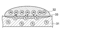
- FIG. 4 is a schematic diagram for explaining that the melting point increases as the amount of Ti mixed with Al increases.
- FIG. 4 is a schematic diagram for explaining that the melting point increases as the amount of Ti mixed with Al increases.
- FIG. 4 is a schematic diagram for explaining that the melting point increases as the amount of Ti mixed with Al increases.
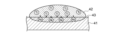
- the melting point decreases as the amount of Ni mixed with Ti increases.
- FIG. 7B is a diagram showing a cross section that appears when FIG. 7A is cut along the bb cross section.
- FIG. 7C is a schematic cross-sectional view illustrating a procedure for forming a region surrounded by a broken line in FIG. 7B.
- FIG. 7C is a schematic cross-sectional view illustrating a procedure for forming a region surrounded by a broken line in FIG. 7B.
- FIG. 7C is a schematic cross-sectional view illustrating a procedure for forming a region surrounded by a broken line in FIG. 7B.
- FIG. 7C is a schematic cross-sectional view illustrating a procedure for forming a region surrounded by a broken line in FIG. 7B. It is a typical sectional view explaining the formation procedure of the joint field located above the upper surface of an enlarged diameter part.
- FIG. 12B is a cross-sectional view of the three-dimensional layered object shown in FIG. It is a figure for explaining an example of section shape of a three-dimensional fabrication object concerning some embodiments.
- FIG. 17 is a diagram in which a bonding region is simplified and described in order to explain a method of forming a bonding region in the three-dimensional layered structure shown in FIG. 16.
- FIG. 17 is a diagram illustrating an example of a case where an insert member as illustrated in FIG. 14 is applied to the three-dimensionally manufactured structure illustrated in FIG. 16.
- FIG. 17 is a view showing another example in which an insert member as shown in FIG. 14 is applied to the three-dimensional stacked structure shown in FIG. 16.
- An existing state shall also be represented.
- the expression representing a shape such as a square shape or a cylindrical shape not only represents a shape such as a square shape or a cylindrical shape in a strictly geometrical sense, but also an uneven portion or a chamfer as long as the same effect can be obtained.
- a shape including a part and the like is also represented.
- the expression “comprising”, “comprising”, “including”, “including”, or “having” one component is not an exclusive expression excluding the existence of another component.
- FIG. 1 is a diagram schematically illustrating a configuration of a three-dimensional additive manufacturing apparatus 1 to which an additive manufacturing method according to some embodiments can be applied.
- the three-dimensional additive manufacturing apparatus 1 according to one embodiment is a modeling apparatus based on an LMD (Laser Metal Deposition) method, and applies a laser beam or the like to a metal powder or the like that is a material of a three-dimensional additive manufacturing article (three-dimensional additive manufacturing article).
- This is an apparatus for forming a three-dimensional stacked structure 2 by irradiating an energy beam to melt, spraying the melted metal powder, solidifying and stacking.
- the three-dimensional additive manufacturing apparatus 1 according to one embodiment includes a light source 5, a nozzle 7, and a modeling table 9.
- the light source 5 generates an energy beam 11 such as a laser beam.
- the energy beam 11 from the light source 5 is emitted toward the modeling table 9.
- the nozzle 7 supplies a metal powder 13, which is a raw material of the three-dimensional layered product 2, from the tip of the nozzle 7 onto the modeling table 9.
- the metal powder 13 supplied from the tip of the nozzle 7 scanned as indicated by the arrow 15 is supplied onto the modeling table 9 in a state of being heated and melted by the energy beam 11.
- the three-dimensional additive manufacturing apparatus 1 of one embodiment can form a linear bead extending on the modeling table 9 along the scanning direction of the nozzle 7.
- the three-dimensional additive manufacturing apparatus 1 of one embodiment can form a planar metal layer by repeating the scanning of the nozzle 7. That is, the metal layer formed by the three-dimensional additive manufacturing apparatus 1 of one embodiment is a set of linear beads.
- the three-dimensional layered manufacturing apparatus 1 of one embodiment can form the three-dimensional layered object 2 by laminating a plurality of the metal layers
- the three-dimensional additive manufacturing apparatus 1 of one embodiment can change the type of the metal powder 13 supplied from the nozzle 7. That is, the three-dimensional additive manufacturing apparatus 1 of one embodiment is provided with at least two supply systems (not shown) of the metal powder 13.
- the three-dimensional layered manufacturing apparatus 1 of one embodiment can form the three-dimensional layered object 2 using at least two kinds of metal powders 13 as raw materials by appropriately switching the supply system.
- a metal powder of a certain kind of metal for example, referred to as a first metal
- a metal powder of a second metal different in kind from the first metal are used.
- a part composed of a first metal (hereinafter, also referred to as a first metal part 21) and a part composed of a second metal (hereinafter, also referred to as a second metal part 22) are used as raw materials.
- the three-dimensional layered object 2 can be formed.
- a three-dimensional stacked structure in which dissimilar metal materials are joined such as the three-dimensional stacked structure 2, is also referred to as a joining member.
- FIG. 1 schematically shows a state in which a first metal portion 21 is formed by stacking a plurality of first layers 21a formed of a first metal.
- FIG. 1 schematically shows a state in the middle of forming the first layer of the second layer 22a formed of the second metal on the upper surface of the first metal part 21.
- mixing of the first metal and the second metal occurs near the joint interface between the first metal and the second metal.
- the first metal part surface Is melted and mixed into the molten second metal.
- the first metal is mixed with the molten second metal, so that a fragile region is generated by an intermetallic compound of the first metal and the second metal. If a fragile region is generated at the joining interface between dissimilar metal materials, the joining strength at the joining interface decreases, and the strength of the joining member decreases.
- the combination of the first metal and the second metal is, for example, a combination capable of forming a solid solution of the first metal and the second metal
- the combination is not an intermetallic compound of the first metal and the second metal but a solid solution. The formation of a fragile region due to the intermetallic compound can be suppressed.
- FIG. 2 is a diagram showing some examples of a binary system phase diagram.
- FIG. 2 illustrates, for example, a Ni—Ti phase diagram, a Fe—Ti phase diagram, a Ti—Al phase diagram, and an Fe—Al phase diagram.
- a region 51 in each phase diagram indicates a region where only a solid solution is obtained, and a region 52 indicates a region where only an intermetallic compound and a solid solution or only an intermetallic compound is obtained.
- Ni—Ti a solid solution can be obtained when Ni is used as a main component metal and Ti is used as an additional metal. Therefore, by forming a layer of Ni on the surface of the portion composed of Ti already formed, Ti is mixed into the molten Ni from the portion composed of Ti, and the interface between Ni and Ti is formed. In the vicinity, a solid solution of Ni and Ti can be formed. Thereby, since the formation of the fragile region due to the intermetallic compound can be suppressed, the decrease in the strength of the joining member between Ni and Ti can be suppressed.
- a solid solution is obtained when Ti is used as a main component metal and Al is used as an additional metal.
- Fe—Al system a solid solution is obtained when Fe is used as a main component metal and Al is used as an additional metal. It can be seen that a solid solution is obtained. Therefore, by forming a layer of Ti on the surface of a portion composed of Al already formed, a solid solution of Ti and Al can be formed near the interface between Ti and Al. In addition, by forming an Fe layer on the surface of a portion already formed of Al, a solid solution of Fe and Al can be formed near the interface between Fe and Al. As is clear from FIG. 2, in the Fe-Ti system, Fe is used as the main component metal and Ti is used as the additional metal, or when Ti is used as the main metal and Fe is used as the additional metal. Even if there is, it turns out that a solid solution cannot be obtained.
- the melting point when another metal as an additional metal is mixed with the main component metal, as shown by a phase boundary line 55 represented by a bold solid line, the melting point may increase as the mixing amount increases. is there. In FIG. 2, when another metal as an additional metal is mixed with the main component metal, the melting point may decrease as the mixing amount increases, as indicated by a phase boundary line 56 indicated by a bold broken line. is there.
- the melting point In the Fe—Al phase diagram, when Al is the main component metal and Fe is the additional metal, there is a region where the melting point decreases as the amount of Fe mixed in increases. 2, the illustration is omitted.
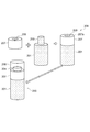
- FIGS. 3A to 3C are schematic diagrams for explaining that the melting point increases as the amount of Ti mixed with Al increases.
- the melting point of the mixed portion is higher than the melting point of Al32, and the mixed portion 34 is solidified as shown in FIG. 3B.
- a layer (mixed layer) 34A in which the mixed portion 34 of Ti and Al is solidified is formed between the portion 31 composed of Ti and the molten Al32. Therefore, mixing of Ti and molten Al32 from the portion 31 where the mixed layer 34A is made of Ti is prevented from progressing. Thereafter, as shown in FIG. 3C, the molten Al32 solidifies to form an Al layer 35.
- the mixed layer 34A in which Al is a main component metal an intermetallic compound of Al and Ti is generated by mixing Ti.
- the thickness of the mixed layer 34A is smaller than the thickness of the Al layer 35, the thickness of the fragile region is smaller than the thickness of the Al layer 35. For this reason, the effect on the strength of the joining member between Ti and Al can be reduced.
- FIGS. 4A to 4D are schematic diagrams for explaining that the melting point increases as the amount of Ni mixed with Ti increases.
- the first metal and the second metal when forming the second metal layer on the already formed first metal portion, in order to suppress a decrease in the strength of the joining member, the first metal and the second metal must be combined. It is desirable that the combination satisfies at least one of the following conditions (a) and (b).
- a combination in which the melting point increases as the amount of the first metal added increases
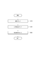
- FIG. 5 is a flowchart illustrating a processing procedure in the additive manufacturing method according to some embodiments.
- the additive manufacturing method according to some embodiments includes a selecting step S10, a first layer forming step S20, and a second layer forming step S30.
- the selecting step S10 is a step of selecting a first metal and a second metal which are combinations capable of forming a solid solution as in the above condition (a) or combinations in which the melting point is increased as in the above condition (b). .
- a combination of metal materials that satisfies at least one of the above conditions (a) and (b) is selected based on, for example, a state diagram as shown in FIG.
- a metal (first metal) for forming a portion in the first layer and a metal (second metal) for forming a layer later are determined.
- the type of the first metal and the second metal may be determined and determined by a person based on the state diagram.
- information about a combination of metals satisfying at least one of the above conditions (a) and (b) information about a state diagram as shown in FIG.
- the CPU of the computer may determine what kind of metal the first metal and the second metal are.
- the first layer forming step S20 is a step of melting and solidifying the powder of the first metal to form the first layer 21a using the three-dimensional layered manufacturing apparatus 1 of one embodiment.
- a first metal portion 21 (see FIG. 1) made of the first metal is formed by laminating a plurality of first layers 21a of the first metal.
- the second metal powder is melted and solidified using the three-dimensional additive manufacturing apparatus 1 of one embodiment, and the second metal powder is formed on the first layer 21a (the first metal part 21). This is a step of forming the layer 22a.
- a second metal layer 22 (see FIG. 1) made of the second metal is formed on the first metal section 21 by laminating a plurality of second layers 22a of the second metal.
- the additive manufacturing method includes the first layer forming step S20 and the second layer forming step S30.
- the first metal and the second metal are a combination that satisfies at least one of the above conditions (a) and (b).
- first metal and the second metal are a combination capable of forming a solid solution as described above, even if the first metal is mixed into the molten second metal during the formation of the second layer 22a, Instead of an intermetallic compound of the first metal and the second metal, a solid solution can be generated. Thereby, since the formation of the fragile region due to the intermetallic compound can be suppressed, the decrease in the strength of the three-dimensional stacked structure 2 that is the joining member between the first metal and the second metal can be suppressed.
- first metal and the second metal are a combination in which the melting point increases as described above, the first metal melted into the molten second metal during the formation of the second layer 22a may cause the first metal to be mixed.
- the melting point in the mixed portion 24 of the metal and the second metal rises above the melting point of the second metal and solidifies. Thereby, a layer (mixed layer 24A) in which the mixed portion 24 of the first metal and the second metal is solidified is formed between the first layer 21a and the molten second metal.
- the mixed layer 24A suppresses the incorporation of the first metal into the second metal melted from the first layer 21a, so that the formation of a fragile region due to the intermetallic compound can be suppressed, and the first metal The strength of the three-dimensional modeled object 2 as a joining member between the three-dimensional structure and the second metal can be suppressed.
- the additive manufacturing method further includes a selection step S10.
- the first metal and the second metal form a combination capable of forming a solid solution as described above, or a combination in which the melting point increases as described above, so that the vicinity of the interface between the first layer and the second layer is increased.
- the formation of a fragile region due to the intermetallic compound can be suppressed, and a decrease in the strength of the three-dimensional stacked structure 2 as a joining member between the first metal and the second metal can be suppressed.
- the second layer 22a is formed under construction conditions such that the content of the first metal in the second layer 22a is equal to or less than a limit at which a solid solution as described above can be formed.
- the pulse duty of the energy beam 11 is a parameter representing a ratio of an irradiation time of the energy beam 11 per unit time.
- the second layer 22a made of the second metal is further laminated on the mixed layer 44A
- the second layer 22a newly laminated on the second layer 22a is higher than the second layer 22a already laminated.
- the layer 22a has a lower first metal content. That is, the content of the first metal is lower in the second layer 22a far from the mixed layer 44A than in the second layer 22a close to the mixed layer 44A. This is because the first metal mixed into the newly formed second layer 22a is the first metal contained in the second layer 22a already formed under the newly formed second layer 22a. This is because it is derived.
- the second layer 22a made of the second metal when the second layer 22a made of the second metal is further laminated on the mixed layer 44A, the hardness of the second layer 22a close to the mixed layer 44A increases and becomes weak, but the second layer 22a is separated from the mixed layer 44A. In the second layer 22a, the rate of increase in hardness decreases.
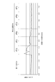
- FIG. 6 is an example of a graph in which the hardness of a member formed by laminating a plurality of second layers 22a of Ti as the second metal on the upper surface of the first metal portion 21 where the first metal is Fe is measured. is there. As shown in FIG. 6, the hardness of the first layer of the second layer 22a is hard, but the hardness of the fourth layer and thereafter is equal to the hardness of the first metal part 21 side.
- the influence of the mixing of the first metal in the second layer 22a in the second layer forming step S30 when neither of the above conditions (a) and (b) is satisfied, the influence of the mixing of the first metal in the second layer 22a in the second layer forming step S30.
- the second layer 22a is laminated by reducing at least one of the height and width of a bead forming the second layer 22a to a predetermined number of laminations that can be substantially ignored.
- the output of the energy beam 11, the pulse duty of the energy beam 11, the scanning speed of the nozzle 7, the supply speed of the metal powder 13, and the like may be appropriately adjusted.
- the height of the bead is the size of the bead along the laminating direction of the second layer 22a
- the width of the bead is along the scanning direction of the nozzle 7 and the direction orthogonal to the laminating direction of the second layer 22a. The size of the bead.
- the second layer 22a may be stacked by reducing at least one of the height and the width of the beads forming the second layer 22a up to a predetermined number of layers.
- the bonding strength (bonding strength) between the first metal part 21 and the second metal part 22 is determined at the interface between the first metal part 21 and the second metal part 22. It depends on the bonding strength. However, it is conceivable to secure the bonding strength between the first metal part 21 and the second metal part 22 by mechanically connecting the first metal part 21 and the second metal part 22. Therefore, in the additive manufacturing method according to some embodiments described below, the first metal part 21 and the second metal part 22 are formed by forming a coupling part that mechanically couples the first metal part 21 and the second metal part 22. The bonding strength with the second metal part 22 is ensured.
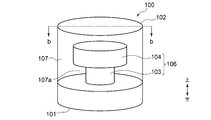
- FIG. 7A is a schematic diagram illustrating an example of the coupling unit.
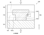
- FIG. 7B is a diagram showing a cross section that appears when FIG. 7A is cut along the bb cross section.
- the lower part in the figure is referred to as a lower metal part 101
- the upper part in the figure is referred to as an upper metal part 102.
- 7A has a lower metal part 101 made of metal A and an upper metal part 102 made of metal B different from metal A.
- the illustrated vertical direction in FIG. 7A is the same as the vertical direction at the time of additive manufacturing of the three-dimensional additive manufacturing object 100. That is, the three-dimensional layered structure 100 shown in FIG. 7A is formed by laminating metal layers in order from the bottom in the figure.
- the reduced-diameter portion 103 protruding upward from the upper surface of the lower metal portion 101 and an enlarged-diameter portion 104 formed on the upper portion of the reduced-diameter portion 103.
- the reduced diameter portion 103 and the increased diameter portion 104 have a columnar shape. Therefore, the direction perpendicular to the up-down direction in the reduced diameter portion 103 and the increased diameter portion 104 is referred to as a radial direction.
- a direction perpendicular to the up-down direction may be referred to as a radial direction.
- a radial direction For example, in each figure after FIG.
- a direction perpendicular to the vertical direction in the part may be referred to as a radial direction, and the radial dimension is a diameter, an outer diameter, Sometimes referred to as the inner diameter.
- the reduced diameter portion 103 has an outer diameter smaller than the outer diameter of the lower metal portion 101.
- the enlarged diameter portion 104 has an outer diameter smaller than the outer diameter of the lower metal portion 101 and larger than the outer diameter of the reduced diameter portion 103.
- the reduced diameter portion 103 and the increased diameter portion 104 constitute a connection region 106 composed of metal A and continuing from the lower metal portion 101.
- the outer surfaces of the reduced diameter portion 103 and the enlarged diameter portion 104 are covered with a coupling region 107 made of metal B and connected to the upper metal portion 102, and are joined to the metal B forming the coupling region 107.
- the reduced diameter portion 103 and the enlarged diameter portion 104 each have a columnar shape, but the reduced diameter portion 103 may have an elliptical column shape or a prismatic shape. May have an elliptical column shape or a prism shape. Further, the reduced diameter portion 103 and the enlarged diameter portion 104 may have column shapes having different cross-sectional shapes, such as the reduced diameter portion 103 having a cylindrical shape and the enlarged diameter portion 104 having a prismatic shape.
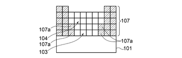
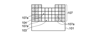
- a portion 107a of the coupling region 107 made of metal B enters under the enlarged diameter portion 104. Therefore, in the three-dimensional layered structure 100 shown in FIG. 7A, as shown in a region surrounded by a broken line 91 in FIG. 7B, the enlarged diameter portion 104 and a part of the coupling region 107 that enters below the enlarged diameter portion 104. The region 107a is fitted. That is, in the three-dimensionally modeled product 100 shown in FIG. 7A, the lower metal portion 101 and the upper metal portion 102 are mechanically separated by the bonding region 106 made of metal A and the bonding region 107 made of metal B. A connecting portion 110 is formed to be connected to each other.
- a step of forming the connection part 110 may be further provided in the additive manufacturing method according to some embodiments. That is, the step of forming the coupling portion 110 includes the coupling region 107 connected to the upper metal portion 102 and the coupling region 106 connected to the lower metal portion 101, and the coupling region 107 connected to the upper metal portion 102. And forming a coupling portion 110 that mechanically couples the upper metal portion 102 and the lower metal portion 101 to each other with the coupling region 106 connected to the lower metal portion 101.
- a part of the bonding region 106 connected to the lower metal portion 101 is connected to the bonding region 107 connected to the upper metal portion 102.
- Each coupling region 106, 107 is formed so as to be located above a part (region 107a to be described later).
- the lower metal part 101 is mechanically coupled to the bonding region 106 made of the metal A and the bonding region 107 made of the metal B. Since the upper metal part 102 can be connected to the upper metal part 102, the strength of the three-dimensional stacked structure 100, which is a joining member between the lower metal part 101 and the upper metal part 102, can be improved.
- the types of the metal A and the metal B are selected so that the influence on the strength of the region surrounded by the broken line 91 is reduced.
- the three-dimensional additive manufacturing object 100 is formed by sequentially stacking metal layers from below to above. For example, paying attention to a region surrounded by a broken line 91, in a portion of the enlarged diameter portion 104 having a larger diameter than the reduced diameter portion 103, the enlarged diameter portion 104 made of metal A is placed on the coupling region 107 made of metal B. Will be formed. Therefore, according to the conditions (a) and (b) already described for the combination of the first metal and the second metal, the combination of the metal A and the metal B is at least one of the following (a1) or (b1) It is desirable that these conditions are satisfied.
- B1 When metal B as an additional metal is added to metal A as a main component metal. , A combination in which the melting point increases as the amount of metal B added increases
- the metal A is made of Ni and the metal B is made of Ti, so that the interface between the lower surface of the enlarged-diameter portion 104 and a part of the bonding region 107 in contact with the lower surface is formed. In the vicinity, a solid solution of Ni and Ti can be formed. In this case, the above condition (a1) is satisfied.
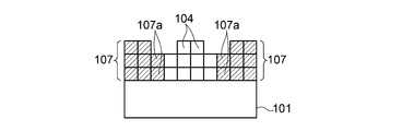
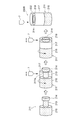
- FIGS. 8A to 8D are schematic cross-sectional views illustrating a procedure for forming a region surrounded by a broken line 91 in FIG. 7B.
- the small squares in FIGS. 8A to 8D and FIGS. 9A to 9D to be described later imitate beads, and one of the squares represents a cross section of a bead formed by one scan of the nozzle 7. ing.
- FIG. 7A since a bead is formed in a circular shape, in the sectional views of FIGS. 8A to 8D and FIGS. May be formed by one scan in which the nozzle 7 makes one round in the circumferential direction with respect to the center line.
- FIGS. 8A to 8D and FIGS. May be formed by one scan in which the nozzle 7 makes one round in the circumferential direction with respect to the center line.
- the size of each cell is larger than the actual cross section of the bead for convenience of explanation.
- a portion of the enlarged diameter portion 104 having a larger diameter than the reduced diameter portion 103 is expressed as if it were formed by one scan that makes one round along the circumferential direction.
- the portion is formed by a plurality of scans.
- a partial region 107a of the bonding region 107, and the partial region 107a A coupling region 107 at the same height position is formed. After that, the reduced diameter portion 103 is formed.
- a solid solution of Ni and Ti is formed near the interface between the reduced diameter portion 103 and the region 107a. Become. Thereby, the formation of the fragile region due to the intermetallic compound can be suppressed, so that the decrease in the strength of the three-dimensional structure can be suppressed.
- the metal A and the metal B satisfy the above condition (b1), if the molten metal B derived from the region 107a is mixed into the molten metal A during the formation of the reduced diameter portion 103, the metal The melting point in the mixed portion of A and metal B rises above the melting point of metal A and solidifies. As a result, a layer (mixed layer) in which the mixed portion of the metal A and the metal B is solidified is formed between the region 107a and the molten metal A. Therefore, the mixed layer suppresses the incorporation of the metal B into the molten metal A from the region 107a, so that the formation of a fragile region due to the intermetallic compound can be suppressed, and the strength of the three-dimensional stacked structure 100 can be reduced. Reduction can be suppressed.
- the reduced diameter portion 103 is formed first at a position away from a region 107a existing radially outside the reduced diameter portion 103, and sequentially shown in FIG. 8B. As shown, the reduced diameter portion 103 is formed radially outward. As described above, when the reduced diameter portion 103 is formed, by forming the reduced diameter portion 103 first from a position distant from the region 107a, the region of the reduced diameter portion 103 in which Ti derived from the region 107a is mixed is enlarged. Can be suppressed.
- the reduced-diameter portion 103 (tentatively referred to as a reduced-diameter portion first region) is formed first from a position adjacent to the region 107a, the Ti mixed in the reduced-diameter portion first region becomes After that, it is further mixed into the reduced diameter portion 103 (provisionally called the reduced diameter portion second region) formed adjacent to the reduced diameter portion first region. Therefore, if the reduced diameter portion 103 is formed first from a position adjacent to the region 107a, the region where Ti originating from the region 107a is mixed increases.
- the reduced diameter portion 103 by forming the reduced diameter portion 103 first from a position distant from the region 107a, the Ti derived from the region 107a in the reduced diameter portion 103 is formed. This suppresses the expansion of the region in which is mixed.
- a bonding region 107 at the same height position as the enlarged diameter portion 104 is formed. deep. After that, the enlarged diameter portion 104 is formed. Thereby, even if Ti derived from the bonding region 107 is mixed in the Ni beads forming the enlarged diameter portion 104, a solid solution of Ni and Ti is formed near the interface between the enlarged diameter portion 104 and the coupling region 107. It will be.
- a bonding region 107 at the same height position as the enlarged diameter portion 104 is formed. deep.
- the enlarged diameter portion 104 is formed.
- the enlarged diameter portion 104 is formed first at a position apart from the coupling region 107 existing radially outside the enlarged diameter portion 104, and sequentially as shown in FIG. As shown in FIG. 7, the enlarged diameter portion 104 is formed radially outward. As described above, by forming the enlarged-diameter portion 104 first from a position distant from the bonding region 107, it is possible to suppress an increase in the region of the enlarged-diameter portion 104 into which Ti derived from the bonding region 107 is mixed.
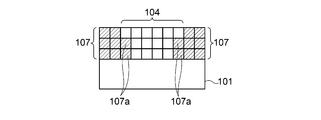
- FIGS. 9A to 9D are schematic cross-sectional views illustrating a procedure for forming the coupling region 107 located above the upper surface of the enlarged diameter portion 104.
- the small squares in FIGS. 9A to 9D simulate a bead as in FIGS. 8A to 8D.
- the bonding region 107 located above the upper surface of the enlarged diameter portion 104 When the bonding region 107 located above the upper surface of the enlarged diameter portion 104 is formed, Ni derived from the enlarged diameter portion 104 is not mixed as much as possible with Ti constituting the bonding region 107, that is, in the enlarged diameter portion 104. As shown in FIGS. 9A and 9B, the bonding region 107 is formed from a position far from the enlarged-diameter portion 104 in order to narrow the bonding region 107 into which the derived Ni is mixed. In addition, the portion immediately above the enlarged diameter portion 104 where the lower metal portion 101 and the upper metal portion 102 do not contribute much to the mechanical bonding strength in the coupling portion 110 is formed later than the other portions.
- the lower metal portion 101 and the upper metal portion 102 are formed in the bonding portion 110.
- the region which contributes little to the mechanical bonding strength is formed at the end of the process of forming the bonding region 107.
- FIG. 10 is a diagram illustrating an example of another embodiment of the coupling unit 110.
- the coupling portions 110 may be respectively formed at a plurality of positions that are different from each other when viewed from the vertical direction, that is, the stacking direction of the metal layers.
- the joint 110 for example, as shown in FIG. 7A, when the joint 110 having a circular shape when viewed from the lamination direction of the metal layers is formed at only one place, for example, If the bonding strength at the interface between the lower metal part 101 and the upper metal part 102 is not sufficient, the lower metal part 101 and the upper metal part 102 rotate about the center axis of the rotating body. There is a risk.
- the coupling portions 110 are formed at a plurality of positions that are different positions when viewed from the lamination direction of the metal layers, the lower metal portion 101 and the upper metal portion can be formed as described above.
- the rotation of the portion 102 with respect to each other as shown by the arrow R can be suppressed. Therefore, the strength of the three-dimensionally manufactured object 100A can be improved with the three-dimensionally manufactured object 100A as shown in FIG.
- the coupling portions 110 may be formed at least at three positions that are not on the same straight line when viewed from the stacking direction of the metal layers. Good.
- each of the joints 110 is formed such that the plurality of joints 110 are present on the same straight line when viewed from the lamination direction of the metal layers, the lower metal part 101
- the strength of the three-dimensional structure may be insufficient with respect to the bending stress acting along the plane perpendicular to the straight line.
- the coupling portions 110 are formed at least at three positions that are not on the same straight line when viewed from the lamination direction of the metal layers, It is possible to suppress the strength of the three-dimensionally manufactured structure 100A from becoming insufficient. Therefore, the strength of the three-dimensionally manufactured object 100A can be improved with the three-dimensionally manufactured object 100A as shown in FIG.
- FIG. 11 is a diagram illustrating an example of another embodiment of the coupling unit 110.
- the coupling portion 110 may be formed so that the shape when viewed from the vertical direction, that is, the stacking direction of the metal layers is a polygon or an ellipse.
- the joint 110 is formed so that the shape when viewed from the lamination direction of the metal layers is circular, for example, If the bonding portion 110 is formed such that the bonding strength at the interface between the lower metal portion 101 and the upper metal portion 102 is not sufficient, the lower metal portion 101 is centered on the center axis of the rotating body. And the upper metal part 102 may rotate with each other.
- the coupling portion 110 by forming the coupling portion 110 such that the shape when viewed from the lamination direction of the metal layers is polygonal or elliptical, it is temporarily assumed that the lower metal portion 101 and the upper metal portion Even when the bonding strength at the interface with the lower metal part 102 is not sufficient, the rotation of the lower metal part 101 and the upper metal part 102 can be suppressed as described above. Therefore, the strength of the three-dimensionally manufactured object 100B can be improved with the three-dimensionally manufactured object 100B as shown in FIG.
- the coupling portion 110 may be formed in a plurality of stages along the direction in which the metal layers are stacked. As described above, by forming the coupling portion 110 in a plurality of stages along the lamination direction of the metal layers, the mechanical coupling strength between the lower metal portion 101 and the upper metal portion 102 can be improved.
- the cross-sectional area of a cross section orthogonal to the stacking direction of the metal layers in the connecting portions 110 formed in a plurality of stages is directed upward along the stacking direction.
- the connecting portion 110 may be formed so as to gradually decrease while repeating increase and decrease.
- the cross-sectional area of the cross section orthogonal to the laminating direction of the metal layer in the coupling portion 110 formed in a plurality of steps gradually increases and decreases along the laminating direction while gradually increasing.
- the cross-sectional area of the coupling portion 110 gradually increases while repeatedly increasing and decreasing below the lamination direction, that is, as it approaches the lower metal portion 101.
- the coupling part 110 formed at a position close to the lower metal part 101 In addition to the load acting on the joint 110, the load acting on the joint 110 formed at a position farther from the lower metal part 101 than the joint 110 is borne. Therefore, in view of the strength of the joint 110, it is desirable that the cross-sectional area of the cross section of the joint 110 perpendicular to the lamination direction of the metal layers increases as approaching the lower metal part 101. On the other hand, in the three-dimensional layered structure 100B shown in FIG. 11, the cross-sectional area of the joint 110 gradually increases and decreases as it approaches the lower metal part 101, so that the strength of the joint 110 formed in a plurality of steps is increased. Can be secured.
- FIG. 12A is a diagram illustrating an example of another embodiment of the coupling unit 110.
- FIG. 12B is a cross-sectional view of the three-dimensional layered structure shown in FIG. 12A. 7A, FIG. 10 and FIG. 11 described above has a reduced diameter portion 103 and an enlarged diameter portion 104 having different outer diameters.
- the coupling region 106 may be formed in a conical shape in which the outer diameter gradually increases from below to above.
- FIG. 13 is a diagram for explaining an example of a cross-sectional shape of a three-dimensional layered object according to some embodiments.
- the lower diagram in FIG. 13 is a cross-sectional view of the lower metal part 101 of the three-dimensional stacked structure according to some embodiments
- the upper diagram in FIG. 13 is the three-dimensional stacked structure according to some embodiments. It is sectional drawing of the upper metal part 102 of a modeled object.
- 13 is a diagram of the three-dimensionally manufactured object 100 shown in FIG. 7A
- a right side diagram of FIG. 13 is a diagram of the three-dimensionally manufactured object 100C shown in FIG. 12A. is there.
- the three-dimensional layered product 100D has a shape in which a peak 106a and a valley 106b having an outer diameter smaller than that of the peak 106a repeatedly appear in the metal layer stacking direction, that is, in the vertical direction.
- FIG. 14 is a diagram for describing another embodiment of a three-dimensionally modeled object according to some embodiments.
- the left view in FIG. 14 is a view of another embodiment of the three-dimensional stacked structure 100 shown in FIG. 7A
- the right view in FIG. 14 is a view of the three-dimensional stacked structure 100C shown in FIG. 12A.
- FIG. 6 is a diagram of another embodiment of the present invention.
- the diagram in the center in the left-right direction in FIG. 14 is a diagram of another embodiment of the three-dimensional stacked structure 100D shown in FIG.
- FIG. 14 In the three-dimensional additive manufacturing according to some embodiments, as shown in FIG.
- an insert member 120 is interposed between a coupling region 106 connected to a lower metal portion 101 and a coupling region 107 connected to an upper metal portion 102. are doing. Note that the insert member 120 may be partially interposed only in the joint. When the connecting portion has a double-girder structure, the insert member 120 may be partially interposed only at the intersecting portion.
- a metal (third metal) different from the metal A and the metal B is used.
- the third region (insert member 120) in which a plurality of third layers obtained by melting and solidifying the powder of (i) are laminated with a bonding region 106 continuing from the lower metal portion 101 and a bonding region 107 continuing from the upper metal portion 102. What is necessary is just to form the coupling part 110 so that it may intervene between them.
- the insert member 120 formed of a metal (for example, a third metal) different from the metal A (for example, the first metal) and the metal B (for example, the second metal) is interposed. It is good to let.
- the metal (hereinafter, also referred to as metal C) constituting the insert member 120 can be selected from metals that do not generate much intermetallic compounds between the metal A and the metal B. If possible, the metal C and the metal A constituting the insert member 120 and the metal C and the metal B constituting the insert member 120 satisfy at least one of the conditions (a1) and (b1) described above. It is desirable that the conditions are satisfied.
- the above condition (a1-2), that is, metal C is A combination capable of forming a solid solution when added, or the above-mentioned condition (b1-2), that is, a combination in which, when metal C is added to metal B, the melting point increases as the amount of metal C added increases And it is sufficient.
- a solid solution is formed in the vicinity of the interface between the metal A and the metal forming the insert member 120, or in the vicinity of the interface between the metal B and the metal forming the insert member 120, or the melting point near the interface increases. I do. Thereby, the formation of the fragile region due to the intermetallic compound can be suppressed, so that the strength reduction near the interface can be suppressed.
- the metal A and the metal B have different linear expansion coefficients, a thermal stress is generated near the interface where the metal A and the metal B are in contact with each other due to a change in the temperature of the joining member. Therefore, when the difference between the linear expansion coefficients of the metal A and the metal B is large, the value of the generated thermal stress is larger than when the difference between the linear expansion coefficients is small. It is easy to cause decline.
- the joining portion 110 is formed so that the insert member 120 is interposed between the joining regions 106 and 107, the third metal forming the insert member 120 is formed.
- the thermal stress in the coupling regions 106 and 107 is relaxed by selecting a metal having a linear expansion coefficient between the linear expansion coefficient of the metal A and the linear expansion coefficient of the metal B, or by selecting a soft metal. it can. Thereby, it is possible to suppress a decrease in the strength of the three-dimensional layered object.
- FIG. 15 is a diagram illustrating an example of still another embodiment of the coupling unit 110.
- the crest 106a and the valley 106b whose outer diameter is smaller than the crest 106a are formed.
- a plurality of coupling regions 106 having a shape that appears repeatedly in the direction in which the metal layers are stacked, that is, in the vertical direction, may be provided.
- the shapes of the peaks 106a and the valleys 106b when viewed from above and below may be polygonal such as rectangular, circular or elliptical. There may be.
- FIG. 16 is a diagram illustrating an example of still another embodiment of the coupling unit 110.
- the connection regions 106 and 107 are formed in a cross-girder shape, and the cross-girder portion of the connection region 106 and the cross-girder portion of the connection region 107 fit each other. May be formed with the coupling regions 106 and 107.
- FIG. 16 in order to simply represent the shapes of the coupling regions 106 and 107, in the overall perspective view of FIG. Do not match.
- At least a part of the joint region 106 connected to the lower metal part 101 is formed.
- a plurality of upper girders 142 formed on the upper part of the side girders 141 are formed so as to be arranged in a double girder shape.
- At least a part of the joint region 107 connected to the upper metal part 102 extends in a direction orthogonal to the stacking direction of the metal layers.
- a plurality of lower girders 151 and a plurality of upper girders 152 extending in a direction orthogonal to the lamination direction of the metal layers and intersecting with the extending direction of the lower girders 151 and formed on the lower girders 151. Are formed so as to be arranged in a grid pattern.
- the lower girder 141 and the lower girder 151 extend in the same direction, and the lower girder 141 and the lower girder are provided.
- the lower girder 141 and the lower girder 151 are formed such that the lower girder 141 and the lower girder 151 are alternately arranged along a direction orthogonal to the extending direction of the 151.
- the upper spar 142 and the upper spar 152 extend in the same direction, and the extension of the upper spar 142 and the upper spar 152
- the upper spar 142 and the upper spar 152 are formed such that the upper spar 142 and the upper spar 152 are alternately arranged along a direction orthogonal to the direction.
- the lower girder 141 of the bonding region 106 and the lower girder 151 of the bonding region 107 extend in the same direction. Then, each girder is formed such that one upper girder 142 of the coupling region 106 and one upper girder 152 of the coupling region 107 extend in the same direction.
- the extending direction of the lower girder 141 of the bonding region 106 and the lower girder 151 of the bonding region 107 is orthogonal to the extending direction.
- the lower girder 141 and the lower girder 151 are formed such that the other lower girder 141 of the coupling region 106 and the other lower girder 151 of the coupling region 107 are alternately arranged along the direction.
- in the step of forming the joint portion 110 in the additive manufacturing method according to some embodiments in the direction orthogonal to the extending direction of the upper girder 142 of the bonding region 106 and the upper girder 152 of the bonding region 107.
- the upper spar 142 and the upper spar 152 are formed so that the other upper spar 142 of the coupling region 106 and the other upper spar 152 of the coupling region 107 are alternately arranged along the upper spar 142.
- the connecting region 106 and the connecting region 107 can be directly and mechanically connected to each other by the connecting region 106 and the connecting region 107 formed by the intersecting beams.
- the strength of the three-dimensional layered object 100F, which is a joining member with the metal part 102, can be ensured, and the heat caused by the difference in linear expansion coefficient between the metal forming the lower metal part 101 and the metal forming the upper metal part 102. Stress can be reduced.
- FIG. 17 is a simplified drawing of the bonding regions 106 and 107 in order to explain a method of forming the bonding regions 106 and 107 in the three-dimensional stacked structure 100F shown in FIG.
- a lower metal part 101 made of metal A is formed by additive manufacturing. Then, as shown in the second diagram from the left in FIG. 17, a plurality of lower girders 141 made of metal A are separated from each other on the upper surface of the lower metal part 101 in a direction orthogonal to the direction in which the lower girders 141 extend. And formed. Next, as shown in the third diagram from the left in FIG. 17, the plurality of spaces between the lower girders 141 separated from each other in a direction orthogonal to the extending direction of the lower girders 141 are made of metal B. The lower girder 151 is formed.
- a plurality of upper girders made of metal A are placed on the lower girders 141 and 151.
- 142 and a plurality of upper girders 152 made of metal B are formed.
- the upper surface of lower girder 141, 151 or upper girder 142, 152 shown on the uppermost side is placed on the upper surface of FIG.
- an upper metal portion 102 made of metal B is formed.
- the connecting portion 110 can be mechanically connected to each other by the connecting regions 106 and 107 formed in a cross-girder shape, that is, can be structurally connected to each other.
- the strength of the joining member between the metal part 101 and the upper metal part 102 can be ensured, and the thermal stress caused by the difference in the linear expansion coefficient between the metal A and the metal B can be reduced.
- the bonding region 106 may be formed at the bottom of the frame.
- the number of pairs of the lower girder 151 and the upper girder 152 may be the same as the number of pairs of the lower girder 141 and the upper girder 142 in the bonding region 106 in the bonding region 107.
- the ratio of the bonding region 106 in the cross section extending in the direction orthogonal to the stacking direction of the metal layers in the bonding portion 110 is lower than the lower metal portion 101.
- the coupling portion 110 may be formed so as to decrease as the distance from the upper metal portion 102 decreases.
- the number of the lower girders 141 and the upper girders 142 may be reduced as approaching from the lower metal part 101 to the upper metal part 102, and when viewed from the lamination direction of the metal layers.
- the width and length of each of the lower girder 141 and the upper girder 142 may be reduced.
- the number of the lower girder 151 and the upper girder 152 may be reduced from the upper metal part 102 to the lower metal part 101 as the distance from the upper metal part 102 to the lower metal part 101 increases.
- the width and length of each of the girder 151 and the upper girder 152 may be reduced. As shown in FIG.
- the lower girder 161 and the upper girder 162 of the insert member 160 Regarding the digits 162 and the lower digits 151 and the upper digits 152 in the joint area 107, the number of each digit may be changed based on the same concept, and the width and length of each digit may be changed. Is also good.
- the ratio occupied by the bonding region 106 decreases as the distance from the lower metal portion 101 to the upper metal portion 102 decreases. Is formed, the thermal stress caused by the difference in the linear expansion coefficient between the metal A and the metal B can be more effectively reduced.
- FIG. 18 is a diagram illustrating an example of a case where the insert member 120 illustrated in FIG. 14 is applied to the three-dimensional layered object 100F illustrated in FIG.
- FIG. 19 is a diagram illustrating another example of a case where the insert member 120 illustrated in FIG. 14 is applied to the three-dimensional stacked structure 100F illustrated in FIG.
- a pair of a lower girder 141 and an upper girder 142 arranged in a cross-girder shape as described above is formed in the coupling region 106 continuing from the lower metal unit 101, and is connected to the upper metal unit 102.
- a pair of the lower girder 151 and the upper girder 152 arranged in a grid pattern as described above is formed in the coupling region 107.
- the lower part of the insert member 160 shown in FIG. 18 is made of a metal (third metal) different in type from the metal A and the metal B so as to fit with the lower girder 141 and the upper girder 142 in the joint area 106.
- a pair of a lower spar 161 and an upper spar 162 is formed.
- a metal (third metal) different in type from the metal A and the metal B so as to fit with the lower girder 151 and the upper girder 152 in the coupling region 107.
- a metal (third metal) different in type from the metal A and the metal B so as to fit with the lower girder 151 and the upper girder 152 in the coupling region 107.
- the coupling region 106 and the coupling region 107 are mechanically coupled to each other indirectly via the insert member 160. That is, in the example shown in FIG. 18, the coupling region 106 and the coupling region 107 are not in direct contact.
- the upper spar 162 of the insert member 160 is arranged between the upper spar 142 of the coupling region 106 and the upper spar 152 of the coupling region 107, which are arranged in a direction perpendicular to the vertical direction. May be.
- each of the beams 141, 142, 151, 152, 161, 162 is not necessarily a direction orthogonal to the lamination direction of the metal layers, but a direction intersecting the lamination direction of the metal layers at an angle other than 90 degrees.
- the lower girder 141 and the upper girder 142 do not necessarily have to be orthogonal to each other, and may intersect at an angle other than 90 degrees.
- the lower girder 151 and the upper girder 152 need not necessarily be orthogonal to each other, and may intersect at an angle other than 90 degrees.
- the lower girder 161 and the upper girder 162 may not necessarily be orthogonal to each other, and may intersect at an angle other than 90 degrees.
- FIG. 20 is a schematic diagram for explaining an example of a method of forming one joint by joining two separately manufactured members by additive manufacturing. For example, as shown in FIG. 20, a case where a first member 201 having a columnar protrusion 203 and a second member 207 having a through hole 205 are joined by lamination molding to form one joint 200. This will be described using an example.
- the first member 201 is made of metal D.
- the second member 207 is made of metal E different from metal D.
- the first member 201 may be formed by machining such as cutting or forging, may be formed by casting, or may be formed by additive manufacturing.
- the first member 201 may be obtained by further performing machining such as cutting or forging on a member formed by casting or additive manufacturing.
- the second member 207 may be formed by machining such as cutting, drilling, forging, or the like, may be formed by casting, or may be formed by additive manufacturing.
- the second member 207 may be obtained by further performing machining such as cutting or forging on a member formed by casting or additive manufacturing.
- the protrusion 203 and the through hole 205 are formed such that the protrusion 203 can be inserted into the through hole 205.
- the protrusion 203 may have a prismatic shape instead of a cylindrical shape.
- the through-hole 205 may be a hole having a rectangular cross section instead of a hole having a circular cross section.
- the first member 201 and the second member 207 thus configured are an assembly 208 in which the protrusion 203 is inserted into the through hole 205 as shown in FIG. Then, the metal D powder is melted and solidified in the tip of the protruding portion 203 in the assembly 208 and the region 207a around the through hole 205 on the surface of the second member 207 to form a layer.
- a large diameter portion 204 having a diameter larger than the diameter of the portion 203 is formed.
- the large-diameter portion 204 faces the region 207a of the second member 207, and prohibits the second member 207 from moving along the axial direction of the protrusion 203. Further, since the lower surface of the large diameter portion 204 is joined to the region 207a of the second member 207, the second member 207 is prohibited from rotating about the projection 203 as a rotation axis.
- the third member 209 may be formed on the upper surface of the second member 207 and the upper surface of the large-diameter portion 204 by additive manufacturing.
- the third member 209 may be made of a metal D, may be made of a metal E, or may be made of a metal F different from the metal D and the metal E.
- the through-hole 205 of the second member 207 which is the metal part made of the metal E
- the method includes a step of inserting the columnar protrusion 203 of the member 201.
- the method of forming the bonded article 200 shown in FIG. 20 includes a method of forming the tip of the protrusion 203 inserted into the through hole 205 and at least a part of a region 207 a around the through hole 205 on the surface of the second member 207.
- the first member 201 and the second member 207 which are separately prepared, can be assembled and connected.
- the first member 201 and the second member 207 are made of different kinds of metals, respectively.
- the first member 201 and the second member 207 are made of the same kind of metal. Is also good.
- FIG. 21 is a schematic diagram for explaining another example of a method of forming one joint by joining two separately manufactured members by additive manufacturing.
- a first member 201A having a plurality of columnar protrusions 203 and a second member 207A having a plurality of through-holes 205 are joined by additive manufacturing to form one joint 200A.
- the case will be described as an example.
- the same components as those described in FIG. 20 described above are denoted by the same reference numerals, and detailed description will be omitted.
- the first member 201A is made of metal D.
- the second member 207A is made of metal E different from metal D.
- the first member 201A may be formed by machining such as cutting or forging, may be formed by casting, or may be formed by additive manufacturing.
- the first member 201A may be obtained by further performing machining such as cutting or forging on a member formed by casting or additive manufacturing.
- the second member 207A may be formed by machining such as cutting, drilling, forging, or the like, may be formed by casting, or may be formed by additive manufacturing.
- the second member 207A may be obtained by further performing machining such as cutting or forging on a member formed by casting or additive manufacturing.
- the protrusion 203 and the through hole 205 are formed so that the protrusion 203 can be inserted into the through hole 205.
- the first member 201A and the second member 207A thus configured are an assembly 208A in which each of the projections 203 is inserted into each of the through holes 205 as shown in FIG. Then, the metal D powder is melted and solidified at the tip of the protrusion 203 in the assembly 208A and the region 207a around the through hole 205 on the surface of the second member 207A to form a layer.
- the large diameter portions 204 having a diameter larger than the diameter of the portion 203 are formed.
- Each large diameter portion 204 faces the region 207a of the second member 207, and prohibits the second member 207A from moving along the axial direction of the protrusion 203.
- the lower surface of each large diameter portion 204 and the region 207a of the second member 207A are joined.
- the third member 209A may be formed on the upper surface of the second member 207A and the upper surface of the large-diameter portion 204 by additive manufacturing.
- the third member 209A may be made of the metal D, may be made of the metal E, or may be made of the metal D and a metal F different from the metal E.
- the first member 201A and the second member 207A are made of different kinds of metals, respectively.
- the first member 201A and the second member 207A are made of the same kind of metal. Is also good.
- FIG. 22 is a schematic diagram for explaining an example of a method of forming a portion on a member manufactured in advance by additive manufacturing. For example, as shown in FIG. 22, an example in which a portion extending in the axial direction of the first member 211 is formed on the first member 211 by additive manufacturing will be described.
- the first member 211 has a cylindrical base 215, a first shaft 213 whose base end is connected to the base 215 and protrudes from the base 215, and a first shaft 211 connected to the tip of the first shaft 213.
- a second shaft portion 214 having a larger diameter than the single shaft portion 213 is provided.
- the first member 211 is made of metal D.
- the first member 211 may be formed by machining such as cutting or forging, may be formed by casting, or may be formed by additive manufacturing.
- the first member 211 may be a member formed by casting or additive manufacturing, and further subjected to machining such as cutting or forging.
- the first member 211 While rotating the first member 211 about the axis of the first shaft portion 213, a powder of a metal E different from the metal D is melted and solidified on the outer periphery of the first shaft portion 213 to form a layer.
- the first cylindrical portion 217 is formed.
- the second cylindrical portion 219 is formed by melting and solidifying a powder of the metal E on the outer periphery of the second shaft portion 214 while rotating the columnar base portion 215.
- the second shaft portion 214 faces the region 217a on the end face of the first cylindrical portion 217, and prohibits the first cylindrical portion 217 from moving along the axis of the first shaft portion 213.
- the inner peripheral surfaces of the first cylindrical portion 217 and the second cylindrical portion 219 are joined to the outer peripheral surfaces of the first shaft portion 213 and the second shaft portion 214. This inhibits the first cylindrical portion 217 and the second cylindrical portion 219 from rotating about the first shaft portion 213 and the second shaft portion 214 as a rotation axis.
- the third member 222 may be formed on the end surface of the second shaft portion 214 and the end surface of the second cylindrical portion 219 by additive manufacturing.
- the third member 222 may be made of a metal D, may be made of a metal E, or may be made of a metal F different from the metal D and the metal E.
- the method of forming the joint 200B shown in FIG. 22 includes a step of forming a layer by melting and solidifying a powder of a metal E different from the metal D in the first member 211 made of the metal D. Then, in the step of forming the layer, while rotating the first member 211 about the axis of the first shaft portion 213, the metal E powder is applied to the outer periphery of the first shaft portion 213 and the second shaft portion 214. Is melted and solidified to form a layer. Thereby, the diameter of the base 215 connected to the base end of the first shaft 213 is larger than the diameter of the first shaft 213, and the tip of the first shaft 213 is larger than the diameter of the first shaft 213.
- the first member 211, the first cylindrical portion 217, and the second shaft portion 214 are made of different types of metals.
- the first member 211 and the first cylindrical portion 217 and the second shaft 214 may be made of the same type of metal.
- the first cylindrical portion 217 and the second shaft portion 214 may be made of different types of metals.
- the present invention is not limited to the above-described embodiment, and includes a form in which the above-described embodiment is modified and a form in which these forms are appropriately combined.
- the bonding portion 110 that realizes mechanical bonding when the bonding portion 110 that realizes mechanical bonding is provided, the strength of the bonding member is ensured without depending on the bonding strength at the interface between dissimilar metals. it can. Therefore, among the several embodiments described above, in the case where the coupling portion 110 that realizes mechanical coupling is provided, it is not always necessary to secure the bonding strength at the interface between different metals.
- Three-dimensional additive manufacturing apparatus 21 First metal part 21a First layer 22 Second metal part 22a Second layer 100, 100A to 100H Three-dimensional additive manufacturing object 101 Lower metal part 102 Upper metal part 106, 107 Joining area 110 Joining part 120,160 Insert member
Landscapes
- Engineering & Computer Science (AREA)
- Chemical & Material Sciences (AREA)
- Manufacturing & Machinery (AREA)
- Materials Engineering (AREA)
- Physics & Mathematics (AREA)
- Plasma & Fusion (AREA)
- Optics & Photonics (AREA)
- Health & Medical Sciences (AREA)
- General Health & Medical Sciences (AREA)
- Toxicology (AREA)
- Mechanical Engineering (AREA)
- Composite Materials (AREA)
- Powder Metallurgy (AREA)
- Pressure Welding/Diffusion-Bonding (AREA)
Abstract
少なくとも一実施形態に係る積層造形方法は、第1金属の粉末を溶融して固化させて第1層を形成するステップと、前記第1金属とは種類が異なる第2金属の粉末を溶融して固化させて前記第1層の上に第2層を形成するステップと、を備え、前記第1金属と前記第2金属とは、前記第2金属に前記第1金属が添加されると固溶体を形成可能な組み合わせであるか、又は、前記第2金属に前記第1金属が添加されると、前記第1金属の添加量が増えるにつれて融点が上昇する組み合わせであることを特徴とする。
Description
本開示は、接合物の積層造形方法及び接合部材に関する。
近年、3次元積層造形が種々の製品の製造方法として利用されている。また、例えば、LMD(Laser Metal Deposition)方式による積層造形方法において、異種材料を接合した接合部材を得ることが開示されている(特許文献1参照)。
例えばLMD方式によって積層造形を行う場合、ある金属(第1金属)で構成されている部材の表面に他の金属(第2金属)の粉末を溶融して固化させて第2金属の層を形成することで異種金属材料を接合した接合部材を得ることができる。
しかし、金属の種類によっては、異種金属材料の接合界面において、第1金属と第2金属との金属間化合物による脆弱な領域が生成されてしまう。異種金属材料の接合界面において脆弱な領域が生成されてしまうと、接合界面における接合強度が低下して接合部材の強度が低下してしまう。
しかし、金属の種類によっては、異種金属材料の接合界面において、第1金属と第2金属との金属間化合物による脆弱な領域が生成されてしまう。異種金属材料の接合界面において脆弱な領域が生成されてしまうと、接合界面における接合強度が低下して接合部材の強度が低下してしまう。
上述の事情に鑑みて、本発明の少なくとも一実施形態は、異種金属材料を接合した接合部材の強度低下を抑制することを目的とする。
(1)本発明の少なくとも一実施形態に係る接合物の積層造形方法は、
第1金属の粉末を溶融して固化させて第1層を形成するステップと、
前記第1金属とは種類が異なる第2金属の粉末を溶融して固化させて前記第1層の上に第2層を形成するステップと、
を備え、
前記第1金属と前記第2金属とは、
前記第2金属に前記第1金属が添加されると固溶体を形成可能な組み合わせであるか、又は、
前記第2金属に前記第1金属が添加されると、前記第1金属の添加量が増えるにつれて融点が上昇する組み合わせである
ことを特徴とする。
第1金属の粉末を溶融して固化させて第1層を形成するステップと、
前記第1金属とは種類が異なる第2金属の粉末を溶融して固化させて前記第1層の上に第2層を形成するステップと、
を備え、
前記第1金属と前記第2金属とは、
前記第2金属に前記第1金属が添加されると固溶体を形成可能な組み合わせであるか、又は、
前記第2金属に前記第1金属が添加されると、前記第1金属の添加量が増えるにつれて融点が上昇する組み合わせである
ことを特徴とする。
溶融した第2金属が第1層の表面に付着すると、第1層の一部が溶融して、溶融している第2金属に混入する。そのため、上述したように、第1金属及び第2金属の種類によっては、第1金属と第2金属との金属間化合物による脆弱な領域が生成されてしまう。
その点、上記(1)の方法では、第1金属と第2金属とは、上述したような固溶体を形成可能な組み合わせ、又は、上述したような融点が上昇する組み合わせである。
その点、上記(1)の方法では、第1金属と第2金属とは、上述したような固溶体を形成可能な組み合わせ、又は、上述したような融点が上昇する組み合わせである。
第1金属と第2金属とが、上述したような固溶体を形成可能な組み合わせであれば、第2層の形成時に、溶融している第2金属に第1金属が混入しても、第1金属と第2金属との金属間化合物ではなく、固溶体を生成させることができる。これにより、金属間化合物による脆弱な領域が形成されることを抑制できるので、第1金属と第2金属との接合部材の強度低下を抑制できる。
また、第1金属と第2金属とが、上述したような融点が上昇する組み合わせであれば、第2層の形成時に、溶融した第2金属に溶融した第1金属が混入すると、第1金属と第2金属との混合部における融点が第2金属の融点よりも上昇して凝固する。これにより、第1層と溶融している第2金属との間に、第1金属と第2金属との混合部が凝固した層(混合層)が形成される。そのため、この混合層が第1層から溶融している第2金属への第1金属の混入を抑制するので、金属間化合物による脆弱な領域が形成されることを抑制でき、第1金属と第2金属との接合部材の強度低下を抑制できる。
(2)幾つかの実施形態では、上記(1)の方法において、前記固溶体を形成可能な組み合わせ、又は、前記融点が上昇する組み合わせとなる前記第1金属及び前記第2金属は選定される。
上記(2)の方法によれば、第1金属と第2金属とが上述したような固溶体を形成可能な組み合わせ、又は、上述したような融点が上昇する組み合わせとなるので、第1層と第2層との界面近傍で金属間化合物による脆弱な領域が形成されることを抑制でき、第1金属と第2金属との接合部材の強度低下を抑制できる。
(3)幾つかの実施形態では、上記(1)又は(2)の方法において、前記第2層を形成するステップでは、前記第2層における前記第1金属の含有量が前記固溶体を形成可能な限度以下となるような施工条件で第2層を形成する。
上記(3)の方法によれば、溶融している第2金属に第1金属が混入しても、第1金属と第2金属との金属間化合物ではなく、固溶体を生成させることができる。これにより、金属間化合物による脆弱な領域が形成されることを抑制できるので、第1金属と第2金属との接合部材の強度低下を抑制できる。
(4)幾つかの実施形態では、上記(1)乃至(3)の何れかの方法において、
前記第2金属からなる第2金属部を形成するステップと、
前記第2金属部の上に前記第1金属からなる第1金属部を形成するステップと、
前記第1層が複数層積層された領域であって前記第1金属部に接続される第1領域と、前記第2層が複数層積層された領域であって前記第2金属部に接続される第2領域とを含み、前記第1領域と前記第2領域とによって前記第1金属部と前記第2金属部とを結合する結合部、を形成するステップと、
をさらに備え、
前記結合部を形成するステップでは、前記第2領域の一部が前記第1領域の一部の上方に位置するように前記第1領域及び前記第2領域を形成する。
前記第2金属からなる第2金属部を形成するステップと、
前記第2金属部の上に前記第1金属からなる第1金属部を形成するステップと、
前記第1層が複数層積層された領域であって前記第1金属部に接続される第1領域と、前記第2層が複数層積層された領域であって前記第2金属部に接続される第2領域とを含み、前記第1領域と前記第2領域とによって前記第1金属部と前記第2金属部とを結合する結合部、を形成するステップと、
をさらに備え、
前記結合部を形成するステップでは、前記第2領域の一部が前記第1領域の一部の上方に位置するように前記第1領域及び前記第2領域を形成する。
上記(4)の方法によれば、結合部において、第2領域の一部が第1領域の一部の上方に位置するように第1領域及び第2領域が形成されるので、第2金属部の上に第1金属部が形成される接合部材において、第1金属部と第2金属部とを互いに離間する方向に引張力が作用しても、第1領域の上記の一部と第2領域の上記の一部とが互いに相手側に向かって押圧されるように第1領域及び第2領域に応力が作用する。したがって、第1金属部と第2金属部とが互いに離間する方向に移動することを第1領域の上記の一部及び第2領域の上記の一部が規制する。
これにより、第1金属と第2金属との界面における接合強度だけでなく、第1領域と第2領域との機械的な結合によって第1金属部と第2金属部とを結合できるので、第1金属と第2金属との接合部材の強度を向上できる。
これにより、第1金属と第2金属との界面における接合強度だけでなく、第1領域と第2領域との機械的な結合によって第1金属部と第2金属部とを結合できるので、第1金属と第2金属との接合部材の強度を向上できる。
(5)幾つかの実施形態では、上記(4)の方法において、前記結合部を形成するステップでは、前記第2層の積層方向から見たときの形状が楕円形又は多角形となるように当該第2領域を形成する。
結合部を形成するステップにおいて、第2層の積層方向から見たときの形状が例えば円形となるように当該第2領域を形成した場合のように、回転体となるように当該第2領域を形成した場合、仮に、第1金属と第2金属との界面における接合強度が十分でなかった場合には、当該回転体の中心軸を中心として第1金属部と第2金属部とが互いに回転してしまうおそれがある。
その点、上記(5)の方法によれば、結合部を形成するステップにおいて、第2層の積層方向から見たときの形状が楕円形又は多角形となるように当該第2領域を形成することで、仮に、第1金属と第2金属との界面における接合強度が十分でなかった場合であっても、上記のように、第1金属部と第2金属部とが互いに回転してしまうことを抑制できる。したがって、上記(5)の方法によれば、第1金属と第2金属との接合部材の強度を向上できる。
その点、上記(5)の方法によれば、結合部を形成するステップにおいて、第2層の積層方向から見たときの形状が楕円形又は多角形となるように当該第2領域を形成することで、仮に、第1金属と第2金属との界面における接合強度が十分でなかった場合であっても、上記のように、第1金属部と第2金属部とが互いに回転してしまうことを抑制できる。したがって、上記(5)の方法によれば、第1金属と第2金属との接合部材の強度を向上できる。
(6)幾つかの実施形態では、上記(4)又は(5)の方法において、前記結合部を形成するステップでは、前記第2層の積層方向から見たときに異なる位置となる、複数の位置に前記結合部をそれぞれ形成する。
結合部を形成するステップにおいて、第2領域を上方、すなわち第2層の積層方向から見たときの形状が例えば円形となるような第2領域を1箇所にだけ形成した場合、仮に、第1金属と第2金属との界面における接合強度が十分でなかった場合には、当該回転体の中心軸を中心として第1金属部と第2金属部とが互いに回転してしまうおそれがある。
その点、上記(6)の方法によれば、第2層の積層方向から見たときに異なる位置となる、複数の位置に結合部をそれぞれ形成するので、上記のように、第1金属部と第2金属部とが互いに回転してしまうことを抑制できる。したがって、上記(6)の方法によれば、第1金属と第2金属との接合部材の強度を向上できる。
その点、上記(6)の方法によれば、第2層の積層方向から見たときに異なる位置となる、複数の位置に結合部をそれぞれ形成するので、上記のように、第1金属部と第2金属部とが互いに回転してしまうことを抑制できる。したがって、上記(6)の方法によれば、第1金属と第2金属との接合部材の強度を向上できる。
(7)幾つかの実施形態では、上記(6)の方法において、前記結合部を形成するステップでは、前記第2層の積層方向から見たときに同一直線上ではない位置となる、少なくとも3箇所に前記結合部をそれぞれ形成する。
結合部を形成するステップにおいて、仮に、複数の結合部が第2層の積層方向から見たときに同一直線上に存在するように各結合部を形成した場合、仮に、第1金属と第2金属との界面における接合強度が十分でなかった場合には、当該直線と直交する面に沿って作用する曲げ応力に対して、接合部材の強度が不十分となるおそれがある。
その点、上記(7)の方法によれば、第2層の積層方向から見たときに同一直線上ではない位置となる、少なくとも3箇所に結合部がそれぞれ形成されるので、曲げ応力に対して、接合部材の強度が不十分となることを抑制できる。したがって、上記(7)の方法によれば、第1金属と第2金属との接合部材の強度を向上できる。
その点、上記(7)の方法によれば、第2層の積層方向から見たときに同一直線上ではない位置となる、少なくとも3箇所に結合部がそれぞれ形成されるので、曲げ応力に対して、接合部材の強度が不十分となることを抑制できる。したがって、上記(7)の方法によれば、第1金属と第2金属との接合部材の強度を向上できる。
(8)幾つかの実施形態では、上記(4)乃至(7)の何れかの方法において、前記結合部を形成するステップでは、前記結合部を前記第2層の積層方向に沿って複数段形成する。
上記(8)の方法によれば、結合部を第2層の積層方向に沿って複数段形成することで、第1金属部と第2金属部との機械的な結合強度を向上できる。
(9)幾つかの実施形態では、上記(8)の方法において、前記結合部を形成するステップでは、複数段形成された前記結合部における前記第2領域の前記第2層の積層方向と直交する断面の断面積が、前記積層方向に沿って上方に向かうにつれて徐々に減少するように前記第2領域を形成する。
上記(9)の方法によれば、複数段形成された結合部における第2領域の第2層の積層方向と直交する断面の断面積は、積層方向に沿って上方に向かうにつれて徐々に減少する。換言すると、第2領域の上記断面積は、積層方向に沿った下方、すなわち、第2金属部に近づくにつれて徐々に増加することとなる。
複数段形成された結合部では、第1金属部と第2金属部とが互いに離間する方向に引張されると、第2金属部から近い位置に形成された結合部では、当該結合部に作用する荷重に加えて、当該結合部よりも第2金属部から遠い位置に形成された結合部に作用する荷重を負担することとなる。そのため、結合部の強度の点から、結合部における第2領域の第2層の積層方向と直交する断面の断面積は、第2金属部に近づくにつれて増加することが望ましい。
その点、上記(9)の方法によれば、第2領域の上記断面積が第2金属部に近づくにつれて徐々に増加するので、複数段形成された結合部の強度を確保できる。
複数段形成された結合部では、第1金属部と第2金属部とが互いに離間する方向に引張されると、第2金属部から近い位置に形成された結合部では、当該結合部に作用する荷重に加えて、当該結合部よりも第2金属部から遠い位置に形成された結合部に作用する荷重を負担することとなる。そのため、結合部の強度の点から、結合部における第2領域の第2層の積層方向と直交する断面の断面積は、第2金属部に近づくにつれて増加することが望ましい。
その点、上記(9)の方法によれば、第2領域の上記断面積が第2金属部に近づくにつれて徐々に増加するので、複数段形成された結合部の強度を確保できる。
(10)幾つかの実施形態では、上記(4)乃至(9)の何れかの方法において、
前記第2領域は、
前記第2金属部の上に形成され、前記第2領域の積層方向と直交する断面の断面積が前記第2金属部の断面積よりも小さい第2下部領域と、
前記第2下部領域の上に形成され、前記第2金属部の断面積よりも小さく、前記第2下部領域の断面積よりも大きい第2上部領域と、
を有し、
前記第1領域は、
前記第2下部領域を前記積層方向と直交する方向から取り囲む第1下部領域を有し、
前記結合部を形成するステップでは、前記第2下部領域の形成に先立って、前記第1下部領域を形成する。
前記第2領域は、
前記第2金属部の上に形成され、前記第2領域の積層方向と直交する断面の断面積が前記第2金属部の断面積よりも小さい第2下部領域と、
前記第2下部領域の上に形成され、前記第2金属部の断面積よりも小さく、前記第2下部領域の断面積よりも大きい第2上部領域と、
を有し、
前記第1領域は、
前記第2下部領域を前記積層方向と直交する方向から取り囲む第1下部領域を有し、
前記結合部を形成するステップでは、前記第2下部領域の形成に先立って、前記第1下部領域を形成する。
上記(10)の方法によれば、第2下部領域の形成に先立って、第1下部領域を形成するので、第2下部領域の形成時に、溶融している第2金属に第1下部領域からの第1金属が混入する可能性がある。しかし、上記(10)の方法における第1金属と第2金属との組み合わせは、上記(4)の方法と同様に、上記(1)の方法による組み合わせとなる。
したがって、第1金属と第2金属とが、上述したような固溶体を形成可能な組み合わせであれば、第2下部領域の形成時に、溶融している第2金属に第1下部領域からの第1金属が混入しても、第1金属と第2金属との金属間化合物ではなく、固溶体を生成させることができる。これにより、金属間化合物による脆弱な領域が形成されることを抑制できるので、第1金属と第2金属との接合部材の強度低下を抑制できる。
したがって、第1金属と第2金属とが、上述したような固溶体を形成可能な組み合わせであれば、第2下部領域の形成時に、溶融している第2金属に第1下部領域からの第1金属が混入しても、第1金属と第2金属との金属間化合物ではなく、固溶体を生成させることができる。これにより、金属間化合物による脆弱な領域が形成されることを抑制できるので、第1金属と第2金属との接合部材の強度低下を抑制できる。
また、第1金属と第2金属とが、上述したような融点が上昇する組み合わせであれば、第2下部領域の形成時に、溶融した第2金属に溶融した第1金属が混入すると、第1金属と第2金属との混合部における融点が第2金属の融点よりも上昇して凝固する。これにより、第1下部領域と溶融している第2金属との間に、第1金属と第2金属との混合部が凝固した層(混合層)が形成される。そのため、この混合層が第1下部領域から溶融している第2金属への第1金属の混入を抑制するので、金属間化合物による脆弱な領域が形成されることを抑制でき、第1金属と第2金属との接合部材の強度低下を抑制できる。
(11)幾つかの実施形態では、上記(10)の方法において、前記結合部を形成するステップでは、前記第2下部領域の形成時に、前記第1下部領域から離れた位置から先に前記第2下部領域を形成する。
上記(11)の方法によれば、第2下部領域の形成時に、第1下部領域から離れた位置から先に第2下部領域を形成することで、第2下部領域における、第1下部領域に由来する第1金属が混入する領域が拡大することを抑制できる。
(12)幾つかの実施形態では、上記(10)又は(11)の方法において、前記結合部を形成するステップでは、前記第2上部領域の上部に前記第1層を形成することに先立って、該第1層と同じ高さ位置であって前記第2上部領域から離れた位置から先に前記第1層を積層する。
上記(12)の方法によれば、第2上部領域に由来する第2金属が混入する第1層の範囲を狭めることができる。
(13)幾つかの実施形態では、上記(4)乃至(12)の何れかの方法において、前記結合部を形成するステップでは、前記第1金属及び前記第2金属とは種類が異なる第3金属の粉末を溶融して固化させた第3層が複数層積層された第3領域が前記第1領域と前記第2領域との間に介在するように前記結合部を形成する。
第1金属と第2金属とで線膨張係数が異なると、接合部材の温度変化によって第1金属と第2金属とが接する界面の近傍に熱応力が発生する。そのため、第1金属と第2金属とで線膨張係数の差が大きい場合、線膨張係数の差が小さい場合と比べて発生する熱応力の値が大きくなるので、第1金属と第2金属との接合強度の低下を招きやすい。
その点、上記(12)の方法によれば、第3金属による第3領域が第1領域と第2領域との間に介在するように結合部が形成されるので、第3金属として第1金属の線膨張係数と第2金属の線膨張係数との間の値の線膨張係数を有する金属を選択するか、軟質の金属を選択すること等によって第1領域及び第2領域における熱応力を緩和できる。これにより、接合部材の強度の低下を抑制できる。
その点、上記(12)の方法によれば、第3金属による第3領域が第1領域と第2領域との間に介在するように結合部が形成されるので、第3金属として第1金属の線膨張係数と第2金属の線膨張係数との間の値の線膨張係数を有する金属を選択するか、軟質の金属を選択すること等によって第1領域及び第2領域における熱応力を緩和できる。これにより、接合部材の強度の低下を抑制できる。
(14)幾つかの実施形態では、上記(13)の方法において、
前記第1金属と前記第2金属と前記第3金属とは、
前記第1金属と前記第3金属との何れか一方の金属に他方の金属が添加されると固溶体を形成可能な組み合わせであるか、
前記第2金属と前記第3金属との何れか一方の金属に他方の金属が添加されると固溶体を形成可能な組み合わせであるか、
前記第1金属と前記第3金属との何れか一方の金属に他方の金属が添加されると、前記他方の金属の添加量が増えるにつれて融点が上昇する組み合わせであるか、
前記第2金属と前記第3金属との何れか一方の金属に他方の金属が添加されると、前記他方の金属の添加量が増えるにつれて融点が上昇する組み合わせであるか、
の何れかである。
前記第1金属と前記第2金属と前記第3金属とは、
前記第1金属と前記第3金属との何れか一方の金属に他方の金属が添加されると固溶体を形成可能な組み合わせであるか、
前記第2金属と前記第3金属との何れか一方の金属に他方の金属が添加されると固溶体を形成可能な組み合わせであるか、
前記第1金属と前記第3金属との何れか一方の金属に他方の金属が添加されると、前記他方の金属の添加量が増えるにつれて融点が上昇する組み合わせであるか、
前記第2金属と前記第3金属との何れか一方の金属に他方の金属が添加されると、前記他方の金属の添加量が増えるにつれて融点が上昇する組み合わせであるか、
の何れかである。
上記(14)の方法によれば、第1金属と第3金属との界面近傍や第2金属と第3金属との界面近傍において、金属間化合物による脆弱な領域が形成されることを抑制できるので、界面近傍の強度低下を抑制できる。
(15)本発明の少なくとも一実施形態に係る接合物の積層造形方法は、
第4金属からなる第4金属部を形成するステップと、
前記第4金属部の上に前記第4金属とは種類が異なる第5金属からなる第5金属部を形成するステップと、
前記第4金属の粉末を溶融して固化させた第4層が複数層積層された領域であって前記第4金属部に接続される第4領域と、前記第5金属の粉末を溶融して固化させた第5層が複数層積層された領域であって前記第5金属部に接続される第5領域とを含み、前記第4領域と前記第5領域とによって前記第4金属部と前記第5金属部とを結合する結合部、を形成するステップと、
を備え、
前記結合部を形成するステップでは、前記第4領域の一部が前記第5領域の一部の上方に位置するように前記第4領域及び前記第5領域を形成する
ことを特徴とする。
第4金属からなる第4金属部を形成するステップと、
前記第4金属部の上に前記第4金属とは種類が異なる第5金属からなる第5金属部を形成するステップと、
前記第4金属の粉末を溶融して固化させた第4層が複数層積層された領域であって前記第4金属部に接続される第4領域と、前記第5金属の粉末を溶融して固化させた第5層が複数層積層された領域であって前記第5金属部に接続される第5領域とを含み、前記第4領域と前記第5領域とによって前記第4金属部と前記第5金属部とを結合する結合部、を形成するステップと、
を備え、
前記結合部を形成するステップでは、前記第4領域の一部が前記第5領域の一部の上方に位置するように前記第4領域及び前記第5領域を形成する
ことを特徴とする。
上記(15)の方法によれば、結合部において、第4領域の一部が第5領域の一部の上方に位置するように第4領域及び第5領域が形成されるので、第4金属部の上に第5金属部が形成される接合部材において、第4金属部と第5金属部とを互いに離間する方向に引張力が作用しても、第4領域の上記の一部と第5領域の上記の一部とが互いに相手側に向かって押圧されるように第4領域及び第5領域に応力が作用する。したがって、第4金属部と第5金属部と互いに離間する方向に移動することを第4領域の上記の一部及び第5領域の上記の一部が規制する。
これにより、第4領域と第5領域との機械的な結合によって第4金属部と第5金属部とを結合できるので、第4金属と第5金属との接合部材の強度を確保できる。
これにより、第4領域と第5領域との機械的な結合によって第4金属部と第5金属部とを結合できるので、第4金属と第5金属との接合部材の強度を確保できる。
(16)幾つかの実施形態では、上記(15)の方法において、
前記第4層は、前記第4金属の粉末を溶融して固化させて形成される線状のビードの集合である層が複数層積層されており、
前記結合部を形成するステップでは、前記第5領域の一部の上方に位置する前記第4領域の形成時において、前記第5領域との界面に近い層の形成時には、前記界面から遠い層の形成時よりも前記ビードの厚さを薄くするか、又は、前記ビードの幅を狭くする。
前記第4層は、前記第4金属の粉末を溶融して固化させて形成される線状のビードの集合である層が複数層積層されており、
前記結合部を形成するステップでは、前記第5領域の一部の上方に位置する前記第4領域の形成時において、前記第5領域との界面に近い層の形成時には、前記界面から遠い層の形成時よりも前記ビードの厚さを薄くするか、又は、前記ビードの幅を狭くする。
例えば、Fe-Ti系の合金では、Fe又はTiの何れか一方の金属に他方の金属が混入しても、固溶体は形成されない。また、例えば、Fe-Ti系の合金では、Fe又はTiの何れか一方の金属に他方の金属が混入しても、他方の金属の添加量が増えるにつれて融点が降下する。そのため、FeとTiとの混合層では、FeとTiとが混合することで、混合層の全体でFeとTiとの金属間化合物が生成され、硬度が上昇して脆弱化する。
しかし、この混合層の上にさらに上記一方の金属による層を複数層積層させていくと、該混合層から離れた層の方が該混合層に近い層よりも上記他方の金属の含有量が減少する。そのため、該混合層の上にさらに上記一方の金属による層を複数層積層させていくと、該混合層に近い層では、硬度が上昇して脆弱となるが、該混合層から離れた層では、硬度の上昇割合が減少する。
しかし、この混合層の上にさらに上記一方の金属による層を複数層積層させていくと、該混合層から離れた層の方が該混合層に近い層よりも上記他方の金属の含有量が減少する。そのため、該混合層の上にさらに上記一方の金属による層を複数層積層させていくと、該混合層に近い層では、硬度が上昇して脆弱となるが、該混合層から離れた層では、硬度の上昇割合が減少する。
その点、上記(16)の方法によれば、第5領域の一部の上方に位置する第4領域の形成時において、第5領域との界面に近い層の形成時には、該界面から遠い層の形成時よりもビードの厚さを薄くするか、又は、ビードの幅を狭くする。したがって、第4領域のうち、第5領域との界面に近い第4層が上述したように脆弱化する場合であっても、脆弱となる領域の拡大を抑制できるので、第4金属と第5金属との接合部材の強度低下を抑制できる。
(17)幾つかの実施形態では、上記(15)又は(16)の方法において、
前記結合部を形成するステップでは、
前記第4領域の少なくとも一部について、前記第4層の積層方向と交差する方向に延在する複数の第4下側桁と、前記第4層の積層方向と交差し且つ前記第4下側桁の延在方向と交差する方向に延在して、前記第4下側桁の上部に形成される複数の第4上側桁とが配置されるように形成し、
前記第5領域の少なくとも一部について、前記第5層の積層方向と交差する方向に延在する複数の第5下側桁と、前記第5層の積層方向と交差し且つ前記第5下側桁の延在方向と交差する方向に延在して、前記第5下側桁の上部に形成される複数の第5上側桁とが配置されるように形成し、
前記一の第4下側桁と前記一の第5下側桁とが同じ方向に延在し、且つ、前記一の第4上側桁と前記一の第5上側桁とが同じ方向に延在する。
前記結合部を形成するステップでは、
前記第4領域の少なくとも一部について、前記第4層の積層方向と交差する方向に延在する複数の第4下側桁と、前記第4層の積層方向と交差し且つ前記第4下側桁の延在方向と交差する方向に延在して、前記第4下側桁の上部に形成される複数の第4上側桁とが配置されるように形成し、
前記第5領域の少なくとも一部について、前記第5層の積層方向と交差する方向に延在する複数の第5下側桁と、前記第5層の積層方向と交差し且つ前記第5下側桁の延在方向と交差する方向に延在して、前記第5下側桁の上部に形成される複数の第5上側桁とが配置されるように形成し、
前記一の第4下側桁と前記一の第5下側桁とが同じ方向に延在し、且つ、前記一の第4上側桁と前記一の第5上側桁とが同じ方向に延在する。
上記(17)の方法によれば、結合部において、交差する桁によって形成された第4領域と第5領域とによって、第4領域と第5領域とを直接または間接的に互いに機械的に結合できるので、第4金属部と第5金属部との接合部材の強度を確保できるとともに、第4金属と第5金属との線膨張係数の差に起因する熱応力を緩和できる。
(18)幾つかの実施形態では、上記(17)の方法において、
前記一の第4下側桁及び前記一の第5下側桁の延在方向と交差する方向に沿って前記他の第4下側桁と前記他の第5下側桁とが交互に配置されるように前記第4下側桁及び前記第5下側桁を形成し、
前記一の第4上側桁及び前記一の第5上側桁の延在方向と交差する方向に沿って前記他の第4上側桁と前記他の第5上側桁とが交互に配置されるように前記第4上側桁及び前記第5上側桁を形成する。
前記一の第4下側桁及び前記一の第5下側桁の延在方向と交差する方向に沿って前記他の第4下側桁と前記他の第5下側桁とが交互に配置されるように前記第4下側桁及び前記第5下側桁を形成し、
前記一の第4上側桁及び前記一の第5上側桁の延在方向と交差する方向に沿って前記他の第4上側桁と前記他の第5上側桁とが交互に配置されるように前記第4上側桁及び前記第5上側桁を形成する。
上記(18)の方法によれば、結合部において、交差する桁によって形成された第4領域と第5領域とによって、第4領域と第5領域とを直接、互いに機械的に結合できるので、第4金属部と第5金属部との接合部材の強度を確保できるとともに、第4金属と第5金属との線膨張係数の差に起因する熱応力を緩和できる。
(19)幾つかの実施形態では、上記(17)又は(18)の方法において、前記結合部を形成するステップでは、前記第4上側桁及び前記第4下側桁の対を前記第4金属部から前記第5金属部に向かって少なくとも2対有するように前記第4領域を形成する。
上記(19)の方法によれば、第4上側桁及び第4下側桁の対が1対だけである場合と比べて、第4領域と第5領域との結合段数を増やすことができる。これにより、第4金属と第5金属との線膨張係数の差に起因する熱応力を緩和し易くなる。
(20)幾つかの実施形態では、上記(19)の方法において、前記結合部を形成するステップでは、前記結合部での前記第4層の積層方向と交差する方向に延在する断面において前記第4領域が占める割合が、前記第4金属部から前記第5金属部に近づくにつれて減るように前記結合部を形成する。
上記(20)の方法によれば、結合部での第4層の積層方向と交差する方向に延在する断面において第4領域が占める割合が、第4金属部から第5金属部に近づくにつれて減るように結合部を形成することで、第4金属と第5金属との線膨張係数の差に起因する熱応力をより効果的に緩和できる。
(21)本発明の少なくとも一実施形態に係る接合物の積層造形方法は、
第6金属からなる第6金属部の貫通孔に、前記第6金属とは種類が異なる第7金属からなる第7金属部の柱状の突部を挿通させるステップと、
前記貫通孔に挿通された前記突部の先端、及び、前記第7金属部の表面のうち前記貫通孔の周囲の領域の少なくとも一部に前記第6金属の粉末を溶融して固化させて層を形成するステップと、
を備えることを特徴とする。
第6金属からなる第6金属部の貫通孔に、前記第6金属とは種類が異なる第7金属からなる第7金属部の柱状の突部を挿通させるステップと、
前記貫通孔に挿通された前記突部の先端、及び、前記第7金属部の表面のうち前記貫通孔の周囲の領域の少なくとも一部に前記第6金属の粉末を溶融して固化させて層を形成するステップと、
を備えることを特徴とする。
上記(21)の方法によれば、貫通孔に挿通された突部の先端、及び、第7金属部の表面のうち貫通孔の周囲の領域の少なくとも一部に第6金属の粉末を溶融して固化させて層を形成することで、それぞれ別々に作成した第6金属部と第7金属部とを組み立てて結合することができる。
(22)本発明の少なくとも一実施形態に係る接合物の積層造形方法は、
第8金属からなる第8部材に前記第8金属とは種類が異なる第9金属の粉末を溶融して固化させて層を形成するステップを備え、
前記第8部材は、
基部と、
基端が前記基部に接続されていて前記基部から突出する第1軸状部と、
前記第1軸状部の先端に接続されていて前記第1軸状部よりも径が大きい第2軸状部と、を有し、
前記層を形成するステップでは、前記第1軸状部の軸線を中心に前記第8部材を回転させながら、前記第1軸状部及び前記第2軸状部の外周に前記第9金属の粉末を溶融して固化させて層を形成する
ことを特徴とする。
第8金属からなる第8部材に前記第8金属とは種類が異なる第9金属の粉末を溶融して固化させて層を形成するステップを備え、
前記第8部材は、
基部と、
基端が前記基部に接続されていて前記基部から突出する第1軸状部と、
前記第1軸状部の先端に接続されていて前記第1軸状部よりも径が大きい第2軸状部と、を有し、
前記層を形成するステップでは、前記第1軸状部の軸線を中心に前記第8部材を回転させながら、前記第1軸状部及び前記第2軸状部の外周に前記第9金属の粉末を溶融して固化させて層を形成する
ことを特徴とする。
上記(22)の方法によれば、第1軸状部の基端に接続された基部の径が第1軸状部の径よりも大きく、第1軸状部の先端に第1軸状部よりも径が大きい第2軸状部が形成されている場合であっても、第1軸状部及び第2軸状部の外周に第9金属の粉末を溶融して固化させて層を形成することができる。
(23)本発明の少なくとも一実施形態に係る接合部材は、
第4金属からなる第4金属部と、
前記第4金属部の上に形成され、第4金属とは種類が異なる第5金属からなる第5金属部と、
前記第4金属によって形成されていて前記第4金属部に接続される第4領域と、前記第5金属によって形成されていて前記第5金属部に接続される第5領域とを含み、前記第4領域と前記第5領域とによって前記第4金属部と前記第5金属部とを結合する結合部と、
を備え、
前記結合部は、前記第4領域の一部が前記第5領域の一部の上方に位置する
ことを特徴とする。
第4金属からなる第4金属部と、
前記第4金属部の上に形成され、第4金属とは種類が異なる第5金属からなる第5金属部と、
前記第4金属によって形成されていて前記第4金属部に接続される第4領域と、前記第5金属によって形成されていて前記第5金属部に接続される第5領域とを含み、前記第4領域と前記第5領域とによって前記第4金属部と前記第5金属部とを結合する結合部と、
を備え、
前記結合部は、前記第4領域の一部が前記第5領域の一部の上方に位置する
ことを特徴とする。
上記(23)の構成によれば、結合部において、第4領域の一部が第5領域の一部の上方に位置するので、第4金属部の上に第5金属部が形成されている接合部材において、第4金属部と第5金属部とを互いに離間する方向に引張力が作用しても、第4領域の上記の一部と第5領域の上記の一部とが互いに相手側に向かって押圧されるように第4領域及び第5領域に応力が作用する。したがって、第4金属部と第5金属部と互いに離間する方向に移動することを第4領域の上記の一部及び第5領域の上記の一部が規制する。
これにより、第4領域と第5領域との機械的な結合によって第4金属部と第5金属部とを結合できるので、接合部材の強度を確保できる。
これにより、第4領域と第5領域との機械的な結合によって第4金属部と第5金属部とを結合できるので、接合部材の強度を確保できる。
本発明の少なくとも一実施形態によれば、異種金属材料を接合した接合部材の強度低下を抑制できる。
以下、添付図面を参照して本発明の幾つかの実施形態について説明する。ただし、実施形態として記載されている又は図面に示されている構成部品の寸法、材質、形状、その相対的配置等は、本発明の範囲をこれに限定する趣旨ではなく、単なる説明例にすぎない。
例えば、「ある方向に」、「ある方向に沿って」、「平行」、「直交」、「中心」、「同心」或いは「同軸」等の相対的或いは絶対的な配置を表す表現は、厳密にそのような配置を表すのみならず、公差、若しくは、同じ機能が得られる程度の角度や距離をもって相対的に変位している状態も表すものとする。
例えば、「同一」、「等しい」及び「均質」等の物事が等しい状態であることを表す表現は、厳密に等しい状態を表すのみならず、公差、若しくは、同じ機能が得られる程度の差が存在している状態も表すものとする。
例えば、四角形状や円筒形状等の形状を表す表現は、幾何学的に厳密な意味での四角形状や円筒形状等の形状を表すのみならず、同じ効果が得られる範囲で、凹凸部や面取り部等を含む形状も表すものとする。
一方、一の構成要素を「備える」、「具える」、「具備する」、「含む」、又は、「有する」という表現は、他の構成要素の存在を除外する排他的な表現ではない。
例えば、「ある方向に」、「ある方向に沿って」、「平行」、「直交」、「中心」、「同心」或いは「同軸」等の相対的或いは絶対的な配置を表す表現は、厳密にそのような配置を表すのみならず、公差、若しくは、同じ機能が得られる程度の角度や距離をもって相対的に変位している状態も表すものとする。
例えば、「同一」、「等しい」及び「均質」等の物事が等しい状態であることを表す表現は、厳密に等しい状態を表すのみならず、公差、若しくは、同じ機能が得られる程度の差が存在している状態も表すものとする。
例えば、四角形状や円筒形状等の形状を表す表現は、幾何学的に厳密な意味での四角形状や円筒形状等の形状を表すのみならず、同じ効果が得られる範囲で、凹凸部や面取り部等を含む形状も表すものとする。
一方、一の構成要素を「備える」、「具える」、「具備する」、「含む」、又は、「有する」という表現は、他の構成要素の存在を除外する排他的な表現ではない。
図1は、幾つかの実施形態に係る積層造形方法を適用可能な3次元積層造形装置1の構成の概略を示す図である。
一実施形態の3次元積層造形装置1は、LMD(Laser Metal Deposition)方式による造形装置であり、立体的な積層造形物(3次元積層造形物)の材料である金属粉末等にレーザビーム等のエネルギービームを照射して溶融させ、溶融した金属粉末を吹き付け、固化させて積層することで3次元積層造形物2を造形する装置である。一実施形態の3次元積層造形装置1は、光源5と、ノズル7と、造形台9とを備えている。
一実施形態の3次元積層造形装置1は、LMD(Laser Metal Deposition)方式による造形装置であり、立体的な積層造形物(3次元積層造形物)の材料である金属粉末等にレーザビーム等のエネルギービームを照射して溶融させ、溶融した金属粉末を吹き付け、固化させて積層することで3次元積層造形物2を造形する装置である。一実施形態の3次元積層造形装置1は、光源5と、ノズル7と、造形台9とを備えている。
光源5は、レーザービーム等のエネルギービーム11を発生させる。光源5からのエネルギービーム11は、造形台9に向けて照射される。ノズル7は、ノズル7の先端から造形台9上に3次元積層造形物2の原料である金属粉末13を供給する。矢印15で示すように走査されるノズル7の先端から供給された金属粉末13は、エネルギービーム11によって加熱されて溶融した状態で造形台9上に供給される。このようにして、一実施形態の3次元積層造形装置1は、造形台9上に、ノズル7の走査方向に沿って延在する線状のビードを形成できる。一実施形態の3次元積層造形装置1は、ノズル7の走査を繰り返すことで、面状の金属層を形成することができる。すなわち、一実施形態の3次元積層造形装置1によって形成される金属層は、線状のビードの集合である。一実施形態の3次元積層造形装置1は、この金属層を複数層積層させることで3次元積層造形物2を造形することができる。
また、図示はしないが、一実施形態の3次元積層造形装置1は、ノズル7から供給する金属粉末13の種類を変更することができる。すなわち一実施形態の3次元積層造形装置1は、金属粉末13の図示しない供給系統を少なくとも2系統備えている。一実施形態の3次元積層造形装置1は、当該供給系統を適宜切り替えることによって、少なくとも2種類の金属粉末13を原料とした3次元積層造形物2を造形することができる。具体的には、一実施形態の3次元積層造形装置1では、ある種類の金属(例えば第1金属と呼ぶ)の金属粉末と、第1金属とは種類が異なる第2金属の金属粉末とを原料に用い、第1金属から構成される部位(以下、第1金属部21とも呼ぶ)と、第2金属から構成される部位(以下、第2金属部22とも呼ぶ)とが一体化された3次元積層造形物2を造形することができる。以下の説明では、当該3次元積層造形物2のように、異種金属材料が接合された3次元積層造形物を接合部材とも呼ぶ。
なお、図1では、説明の便宜上、溶融して固化することで形成された金属の層について、隣り合う層との境界を2点鎖線で表しているが、実際には、このような境界は目視によって視認できない場合がある。
また、図1では、第1金属によって形成された第1層21aが複数層積層されて第1金属部21が構成されている様子を模式的に示している。また、図1では、第1金属部21の上面に第2金属によって形成された第2層22aの1層目の形成途中の様子を模式的に示している。
また、図1では、第1金属によって形成された第1層21aが複数層積層されて第1金属部21が構成されている様子を模式的に示している。また、図1では、第1金属部21の上面に第2金属によって形成された第2層22aの1層目の形成途中の様子を模式的に示している。
第1金属部と第2金属部とが接合された3次元積層造形物2では、第1金属と第2金属との接合界面近傍において、第1金属と第2金属との混合が生じる。具体的には、例えば、既に形成されている第1金属部の上に第2金属の層を形成させる場合、溶融した第2金属が第1金属部の表面に付着すると、第1金属部表面の一部が溶融して、溶融している第2金属に混入する。
この時、金属の種類によっては、溶融している第2金属に第1金属が混入することで、第1金属と第2金属との金属間化合物による脆弱な領域が生成されてしまう。異種金属材料の接合界面において脆弱な領域が生成されてしまうと、接合界面における接合強度が低下して接合部材の強度が低下してしまう。
この時、金属の種類によっては、溶融している第2金属に第1金属が混入することで、第1金属と第2金属との金属間化合物による脆弱な領域が生成されてしまう。異種金属材料の接合界面において脆弱な領域が生成されてしまうと、接合界面における接合強度が低下して接合部材の強度が低下してしまう。
しかし、第1金属と第2金属との組み合わせが、例えば第1金属と第2金属との固溶体を形成可能な組み合わせであれば、第1金属と第2金属との金属間化合物ではなく、固溶体を生成させることで、金属間化合物による脆弱な領域が形成されることを抑制できる。
図2は、2元系状態図の幾つかの例を示す図である。図2では、例えばNi-Ti系状態図と、Fe-Ti系状態図と、Ti-Al系状態図と、Fe-Al系状態図とを例示している。各状態図における領域51は、固溶体のみが得られる領域を示し、領域52は、金属間化合物と固溶体、又は、金属間化合物のみが得られる領域を示す。
図2から明らかなように、Ni-Ti系では、Niを主成分金属とし、Tiを添加金属とした場合に固溶体が得られることが分かる。したがって、既に形成されているTiから構成される部位の表面にNiの層を形成させることで、溶融しているNiにTiから構成される部位からTiが混入して、NiとTiとの界面近傍でNiとTiとによる固溶体を形成することができる。これにより、金属間化合物による脆弱な領域が形成されることを抑制できるので、NiとTiとの接合部材の強度低下を抑制できる。
同様に、Ti-Al系では、Tiを主成分金属とし、Alを添加金属とした場合に固溶体が得られ、Fe-Al系では、Feを主成分金属とし、Alを添加金属とした場合に固溶体が得られることが分かる。したがって、既に形成されているAlから構成される部位の表面にTiの層を形成させることで、TiとAlとの界面近傍でTiとAlとによる固溶体を形成することができる。また、既に形成されているAlから構成される部位の表面にFeの層を形成させることで、FeとAlとの界面近傍でFeとAlとによる固溶体を形成することができる。
なお、図2から明らかなように、Fe-Ti系では、Feを主成分金属とし、Tiを添加金属とした場合、及び、Tiを主成分金属とし、Feを添加金属とした場合の何れであっても、固溶体が得られないことが分かる。
なお、図2から明らかなように、Fe-Ti系では、Feを主成分金属とし、Tiを添加金属とした場合、及び、Tiを主成分金属とし、Feを添加金属とした場合の何れであっても、固溶体が得られないことが分かる。
なお、図2において、太線の実線で表した相の境界線55で示すように、主成分金属に対して添加金属としての他の金属が混入すると、混入量が増えるにつれて融点が上昇する場合がある。また、図2において、太線の破線で表した相の境界線56で示すように、主成分金属に対して添加金属としての他の金属が混入すると、混入量が増えるにつれて融点が下降する場合がある。なお、Fe-Al系状態図において、Alを主成分金属とし、Feを添加金属とした場合に、Feの混入量が増えるにつれて融点が下降する領域が存在するが、当該領域が小さいため、図2においては図示を省略する。
例えば、Ti-Al系のように、主成分金属であるAlに対してTiが混入すると、混入量が増えるにつれて融点が上昇する場合について、図3A~図3Cを参照して説明する。なお、図3A~図3Cは、Alに対してTiの混入量が増えるにつれて融点が上昇することを説明するための模式的な図である。
図3Aに示すように既に形成されているTiから構成される部位31に溶融したAl32が付着すると、Tiから構成される部位31の表面が溶融して、Tiから構成される部位31と溶融したAl32との界面33の近傍でTiとAlとが混合する。
界面33の近傍でTiとAlとが混合すると、この混合部の融点がAl32の融点よりも上昇して、図3Bに示すように、当該混合部34が凝固する。これにより、Tiから構成される部位31と溶融しているAl32との間に、TiとAlとの混合部34が凝固した層(混合層)34Aが形成される。そのため、混合層34AがTiから構成される部位31からのTiと溶融したAl32との混合が進行することを防止する。
その後、図3Cに示すように、溶融したAl32が凝固することで、Alの層35が形成される。
なお、Ti-Al系の場合、Alが主成分金属である混合層34Aでは、Tiが混入することでAlとTiとの金属間化合物が生成されている。しかし、混合層34Aの厚さがAlの層35の厚さと比べて薄いため、脆弱な領域の厚さがAlの層35の厚さと比べて薄い。そのため、TiとAlとの接合部材の強度に与える影響を小さくすることができる。
その後、図3Cに示すように、溶融したAl32が凝固することで、Alの層35が形成される。
なお、Ti-Al系の場合、Alが主成分金属である混合層34Aでは、Tiが混入することでAlとTiとの金属間化合物が生成されている。しかし、混合層34Aの厚さがAlの層35の厚さと比べて薄いため、脆弱な領域の厚さがAlの層35の厚さと比べて薄い。そのため、TiとAlとの接合部材の強度に与える影響を小さくすることができる。
上述したTi-Al系の場合とは逆に、Ni-Ti系のように、主成分金属であるTiに対してNiが混入すると、混入量が増えるにつれて融点が下降する場合について、図4A~図4Dを参照して説明する。なお、図4A~図4Dは、Tiに対してNiの混入量が増えるにつれて融点が上昇することを説明するための模式的な図である。
図4Aに示すように既に形成されているNiから構成される部位41に溶融したTi42が付着すると、Niから構成される部位41の表面が溶融して、Niから構成される部位41と溶融したTi42との界面43の近傍でNiとTiとが混合する。
図4Bに示すように、界面43の近傍でNiとTiとが混合すると、この混合部44の融点がTi42の融点よりも下降する。そのため、混合部44が溶融した状態が保たれて、Niから構成される部位41からのNiと溶融したTi42との混合が進行する。当該混合の進行によって溶融したTi42に対するNiの混入量が増えると、混合部44の融点がさらに下降するので、混合部44が溶融した状態が保たれ、Niから構成される部位41からのNiと溶融したTi42との混合がさらに進行する。これにより、図4Cに示すように、溶融領域の全体にわたってNiが混入して混合部44となる。その後、図4Dに示すように、混合部44が凝固して混合層44Aが形成される。
なお、Ni-Ti系の場合、Tiが主成分である混合層44Aでは、Niが混入することでTiとNiとの金属間化合物が生成されている。
なお、Ni-Ti系の場合、Tiが主成分である混合層44Aでは、Niが混入することでTiとNiとの金属間化合物が生成されている。
以上の点を踏まえれば、既に形成されている第1金属部の上に第2金属の層を形成させる場合、接合部材の強度低下を抑制するためには、第1金属と第2金属との組み合わせは、次の(a)又は(b)の少なくとも何れかの条件を満たしていることが望ましい。
(a)主成分金属としての第2金属に添加金属としての第1金属が添加されると固溶体を形成可能な組み合わせ
(b)主成分金属としての第2金属に添加金属としての第1金属が添加されると、第1金属の添加量が増えるにつれて融点が上昇する組み合わせ
(a)主成分金属としての第2金属に添加金属としての第1金属が添加されると固溶体を形成可能な組み合わせ
(b)主成分金属としての第2金属に添加金属としての第1金属が添加されると、第1金属の添加量が増えるにつれて融点が上昇する組み合わせ
そこで、幾つかの実施形態に係る積層造形方法では、上記条件(a)又は(b)の少なくとも何れか一方を満たすようにしている。
図5は、幾つかの実施形態に係る積層造形方法における処理手順を示したフローチャートである。
幾つかの実施形態に係る積層造形方法は、選定ステップS10と、第1層形成ステップS20と、第2層形成ステップS30とを備えている。
図5は、幾つかの実施形態に係る積層造形方法における処理手順を示したフローチャートである。
幾つかの実施形態に係る積層造形方法は、選定ステップS10と、第1層形成ステップS20と、第2層形成ステップS30とを備えている。
選定ステップS10は、上記条件(a)のように固溶体を形成可能な組み合わせ、又は、上記条件(b)のように融点が上昇する組み合わせとなる第1金属及び第2金属を選定するステップである。
具体的には、選定ステップS10では、例えば図2に示したような状態図に基づいて、上記条件(a)又は(b)の少なくとも何れか一方を満たす金属材料の組み合わせを選択して、最初に部位を形成しておく金属(第1金属)と、後から層を形成する方の金属(第2金属)を決定する。なお、第1金属及び第2金属をどの種類の金属とするのかを、状態図に基づいて人が判断して決定するようにしてもよい。また、例えば不図示のコンピュータの記憶部に上記条件(a)又は(b)の少なくとも何れかの条件を満たす金属の組み合わせに関する情報や図2に示したような状態図に関する情報等を記憶させておき、第1金属及び第2金属をどの種類の金属とするのかをコンピュータのCPUが決定するようにしてもよい。
具体的には、選定ステップS10では、例えば図2に示したような状態図に基づいて、上記条件(a)又は(b)の少なくとも何れか一方を満たす金属材料の組み合わせを選択して、最初に部位を形成しておく金属(第1金属)と、後から層を形成する方の金属(第2金属)を決定する。なお、第1金属及び第2金属をどの種類の金属とするのかを、状態図に基づいて人が判断して決定するようにしてもよい。また、例えば不図示のコンピュータの記憶部に上記条件(a)又は(b)の少なくとも何れかの条件を満たす金属の組み合わせに関する情報や図2に示したような状態図に関する情報等を記憶させておき、第1金属及び第2金属をどの種類の金属とするのかをコンピュータのCPUが決定するようにしてもよい。
第1層形成ステップS20は、一実施形態の3次元積層造形装置1を用いて、第1金属の粉末を溶融して固化させて第1層21aを形成するステップである。
第1層形成ステップS20は、第1金属による第1層21aを複数層積層させて、第1金属からなる第1金属部21(図1参照)を形成する。
第1層形成ステップS20は、第1金属による第1層21aを複数層積層させて、第1金属からなる第1金属部21(図1参照)を形成する。
第2層形成ステップS30は、一実施形態の3次元積層造形装置1を用いて、第2金属の粉末を溶融して固化させて第1層21a(第1金属部21)の上に第2層22aを形成するステップである。
第2層形成ステップS30は、第2金属による第2層22aを複数層積層させて、第2金属からなる第2金属部22(図1参照)を第1金属部21の上に形成する。
第2層形成ステップS30は、第2金属による第2層22aを複数層積層させて、第2金属からなる第2金属部22(図1参照)を第1金属部21の上に形成する。
このように、幾つかの実施形態に係る積層造形方法では、第1層形成ステップS20と、第2層形成ステップS30とを備えている。そして、幾つかの実施形態に係る積層造形方法では、第1金属と第2金属とは、上記条件(a)又は(b)の少なくとも何れか一方を満たす組み合わせである。
第1金属と前記第2金属とが、上述したような固溶体を形成可能な組み合わせであれば、第2層22aの形成時に、溶融している第2金属に第1金属が混入しても、第1金属と第2金属との金属間化合物ではなく、固溶体を生成させることができる。これにより、金属間化合物による脆弱な領域が形成されることを抑制できるので、第1金属と第2金属との接合部材である3次元積層造形物2の強度低下を抑制できる。
また、第1金属と第2金属とが、上述したような融点が上昇する組み合わせであれば、第2層22aの形成時に、溶融した第2金属に溶融した第1金属が混入すると、第1金属と第2金属との混合部24(図3B参照)における融点が第2金属の融点よりも上昇して凝固する。これにより、第1層21aと溶融している第2金属との間に、第1金属と第2金属との混合部24が凝固した層(混合層24A)が形成される。そのため、この混合層24Aが第1層21aから溶融している第2金属への第1金属の混入を抑制するので、金属間化合物による脆弱な領域が形成されることを抑制でき、第1金属と第2金属との接合部材である3次元積層造形物2の強度低下を抑制できる。
また、幾つかの実施形態に係る積層造形方法では、選定ステップS10をさらに備えている。
これにより、第1金属と第2金属とが上述したような固溶体を形成可能な組み合わせ、又は、上述したような融点が上昇する組み合わせとなるので、第1層と第2層との界面近傍で金属間化合物による脆弱な領域が形成されることを抑制でき、第1金属と第2金属との接合部材である3次元積層造形物2の強度低下を抑制できる。
これにより、第1金属と第2金属とが上述したような固溶体を形成可能な組み合わせ、又は、上述したような融点が上昇する組み合わせとなるので、第1層と第2層との界面近傍で金属間化合物による脆弱な領域が形成されることを抑制でき、第1金属と第2金属との接合部材である3次元積層造形物2の強度低下を抑制できる。
なお、第2層形成ステップS30では、第2層22aにおける第1金属の含有量が上述したような固溶体を形成可能な限度以下となるような施工条件で第2層22aを形成する。
具体的には、エネルギービーム11の出力、エネルギービーム11のパルスデューティ、ノズル7の走査速度、金属粉末13の供給速度等を調節することによって、施工条件を適宜変更することができる。なお、エネルギービーム11のパルスデューティとは、単位時間当たりのエネルギービーム11の照射時間の割合を表すパラメータである。
具体的には、エネルギービーム11の出力、エネルギービーム11のパルスデューティ、ノズル7の走査速度、金属粉末13の供給速度等を調節することによって、施工条件を適宜変更することができる。なお、エネルギービーム11のパルスデューティとは、単位時間当たりのエネルギービーム11の照射時間の割合を表すパラメータである。
これにより、溶融している第2金属に第1金属が混入しても、第1金属と第2金属との金属間化合物ではなく、固溶体を生成させることができる。これにより、金属間化合物による脆弱な領域が形成されることを抑制できるので、第1金属と第2金属との接合部材である3次元積層造形物2の強度低下を抑制できる。
なお、Fe-Ti系のように、上記条件(a)及び(b)の何れも満たさない場合、第2金属の溶融領域の全体にわたってFeとTiとが混合し、その後、混合部44が凝固してFeとTiとの混合層44Aが形成される(図4C,4D参照)。FeとTiとの混合層44Aでは、FeとTiとが混合することで、混合層44Aの全体でFeとTiとの金属間化合物が生成される。
この混合層44Aの上にさらに第2金属による第2層22aを積層させていくと、既に積層されている第2層22aよりも、該第2層22aの上に新たに積層させた第2層22aの方が第1金属の含有量が少なくなる。すなわち、混合層44Aから離れた第2層22aの方が混合層44Aに近い第2層22aよりも第1金属の含有量が減少する。これは、新たに形成する第2層22aに混入することとなる第1金属は、当該新たに形成する第2層22aの下で既に形成されている第2層22aに含まれる第1金属に由来するものであるからである。
そのため、混合層44Aの上にさらに第2金属による第2層22aを積層させていくと、混合層44Aに近い第2層22aでは、硬度が上昇して脆弱となるが、混合層44Aから離れた第2層22aでは、硬度の上昇割合が減少する。
そのため、混合層44Aの上にさらに第2金属による第2層22aを積層させていくと、混合層44Aに近い第2層22aでは、硬度が上昇して脆弱となるが、混合層44Aから離れた第2層22aでは、硬度の上昇割合が減少する。
図6は、第1金属がFeである第1金属部21の上面に第2金属であるTiによる第2層22aを複数層積層させて形成された部材の硬さを測定したグラフの一例である。図6に示すように、第2層22aの1層目では硬さが硬くなっているが4層目以降では、第1金属部21側の硬さと同等の硬さとなる。
そこで、幾つかの実施形態に係る積層造形方法では、上記条件(a)及び(b)の何れも満たさない場合、第2層形成ステップS30において、第2層22aにおける第1金属の混入の影響が略無視できる所定の積層数まで、第2層22aを形成するビードの高さ又は幅の少なくとも一方を小さくして第2層22aを積層させることとする。
ビードの高さ又は幅の少なくとも一方を小さくするには、エネルギービーム11の出力、エネルギービーム11のパルスデューティ、ノズル7の走査速度、金属粉末13の供給速度等を適宜調節すればよい。
なお、ビードの高さとは、第2層22aの積層方向に沿ったビードの大きさであり、ビードの幅とは、ノズル7の走査方向及び第2層22aの積層方向と直交する方向に沿ったビードの大きさである。
ビードの高さ又は幅の少なくとも一方を小さくするには、エネルギービーム11の出力、エネルギービーム11のパルスデューティ、ノズル7の走査速度、金属粉末13の供給速度等を適宜調節すればよい。
なお、ビードの高さとは、第2層22aの積層方向に沿ったビードの大きさであり、ビードの幅とは、ノズル7の走査方向及び第2層22aの積層方向と直交する方向に沿ったビードの大きさである。
なお、後述するように、第1金属部21と第2金属部22とを機械的に結合する結合部を形成することで、第1金属部21と第2金属部22との結合強度を確保するようにした上で、上述したように、所定の積層数まで、第2層22aを形成するビードの高さ又は幅の少なくとも一方を小さくして第2層22aを積層させてもよい。
これにより、上記条件(a)及び(b)の何れも満たさない場合であっても、硬度が上昇して脆弱となる領域の拡大を抑制できるので、第1金属と第2金属との接合部材である3次元積層造形物2の強度低下を抑制できる。
これにより、上記条件(a)及び(b)の何れも満たさない場合であっても、硬度が上昇して脆弱となる領域の拡大を抑制できるので、第1金属と第2金属との接合部材である3次元積層造形物2の強度低下を抑制できる。
(結合部について)
上述した幾つかの実施形態に係る積層造形方法では、第1金属部21と第2金属部22との接合強度(結合強度)は、第1金属部21と第2金属部22との界面における接合強度に依存している。しかし、第1金属部21と第2金属部22とを機械的に結合することで、第1金属部21と第2金属部22との結合強度を確保することが考えられる。
そこで、以下で説明する幾つかの実施形態に係る積層造形方法では、第1金属部21と第2金属部22とを機械的に結合する結合部を形成することで、第1金属部21と第2金属部22との結合強度を確保するようにしている。
上述した幾つかの実施形態に係る積層造形方法では、第1金属部21と第2金属部22との接合強度(結合強度)は、第1金属部21と第2金属部22との界面における接合強度に依存している。しかし、第1金属部21と第2金属部22とを機械的に結合することで、第1金属部21と第2金属部22との結合強度を確保することが考えられる。
そこで、以下で説明する幾つかの実施形態に係る積層造形方法では、第1金属部21と第2金属部22とを機械的に結合する結合部を形成することで、第1金属部21と第2金属部22との結合強度を確保するようにしている。
図7Aは、結合部の一例を示す模式的な図である。図7Bは、図7Aをb-b断面で切断したとき現れる断面を示す図である。説明の便宜上、以下の説明では、図示下方の部位を下部金属部101と呼び、図示上方の部位を上部金属部102と呼ぶこととする。図7Aに示した3次元積層造形物100は、金属Aから構成される下部金属部101と、金属Aとは異なる金属Bから構成される上部金属部102とを有する。図7Aにおける図示上下方向は、3次元積層造形物100の積層造形時の上下方向と同じ方向である。すなわち、図7Aに示した3次元積層造形物100は、図示下方から順に金属層が積層されて形成されたものである。
図7Aに示した3次元積層造形物100は、下部金属部101の上面から上方に突出する縮径部103と、縮径部103の上部に形成される拡径部104とを有する。図7Aに示した3次元積層造形物100では、縮径部103及び拡径部104は円柱形状を有している。そのため、縮径部103及び拡径部104における、上下方向と直交する方向を径方向と称することとする。なお、説明の便宜上、図7A以降の各図においても、上下方向と直交する方向を径方向と称することがある。例えば、図7A以降の各図において円柱形状や円筒形状ではない部位に対しても、当該部位における上下方向と直交する方向を径方向と称することがあり、径方向の寸法を径、外径、内径等と称することがある。
縮径部103は、下部金属部101の外径よりも小さな外径を有する。拡径部104は、下部金属部101の外径よりも小さく、縮径部103よりも大きな外径を有する。
縮径部103及び拡径部104は、下部金属部101から連なる、金属Aから構成される結合領域106を構成する。
縮径部103及び拡径部104の外表面は、上部金属部102から連なる、金属Bから構成される結合領域107に覆われており、結合領域107を形成する金属Bと接合されている。
なお、説明の便宜上、縮径部103及び拡径部104は、それぞれ円柱形状を有しているが、縮径部103が楕円柱形状や角柱形状を有していてもよく、拡径部104が楕円柱形状や角柱形状を有していてもよい。また、縮径部103が円柱形状を有し、拡径部104が角柱形状を有する等、縮径部103と拡径部104とが互いに異なる断面形状の柱形状を有していてもよい。
縮径部103及び拡径部104は、下部金属部101から連なる、金属Aから構成される結合領域106を構成する。
縮径部103及び拡径部104の外表面は、上部金属部102から連なる、金属Bから構成される結合領域107に覆われており、結合領域107を形成する金属Bと接合されている。
なお、説明の便宜上、縮径部103及び拡径部104は、それぞれ円柱形状を有しているが、縮径部103が楕円柱形状や角柱形状を有していてもよく、拡径部104が楕円柱形状や角柱形状を有していてもよい。また、縮径部103が円柱形状を有し、拡径部104が角柱形状を有する等、縮径部103と拡径部104とが互いに異なる断面形状の柱形状を有していてもよい。
すなわち、拡径部104の下方には、金属Bから構成される結合領域107の一部の領域107aが入り込んだ状態となっている。そのため、図7Aに示した3次元積層造形物100では、図7Bにおける破線91で囲んだ領域のように、拡径部104と、拡径部104の下方に入り込んだ結合領域107の一部の領域107aとが嵌合している。
すなわち、図7Aに示した3次元積層造形物100では、金属Aから構成される結合領域106と、金属Bから構成される結合領域107とによって、下部金属部101と上部金属部102とを機械的に結合する結合部110が形成されている。
すなわち、図7Aに示した3次元積層造形物100では、金属Aから構成される結合領域106と、金属Bから構成される結合領域107とによって、下部金属部101と上部金属部102とを機械的に結合する結合部110が形成されている。
このような結合部110を有する3次元積層造形物100を得るには、幾つかの実施形態に係る積層造形方法において、結合部110を形成するステップをさらに設ければよい。
すなわち、結合部110を形成するステップは、上部金属部102に接続される結合領域107と、下部金属部101に接続される結合領域106とを含み、上部金属部102に接続される結合領域107と下部金属部101に接続される結合領域106とによって上部金属部102と下部金属部101とを機械的に結合する結合部110、を形成するステップである。
そして、幾つかの実施形態に係る積層造形方法では、結合部110を形成するステップでは、下部金属部101に接続される結合領域106の一部が上部金属部102に接続される結合領域107の一部(後述する領域107a)の上方に位置するように各結合領域106,107を形成する。
すなわち、結合部110を形成するステップは、上部金属部102に接続される結合領域107と、下部金属部101に接続される結合領域106とを含み、上部金属部102に接続される結合領域107と下部金属部101に接続される結合領域106とによって上部金属部102と下部金属部101とを機械的に結合する結合部110、を形成するステップである。
そして、幾つかの実施形態に係る積層造形方法では、結合部110を形成するステップでは、下部金属部101に接続される結合領域106の一部が上部金属部102に接続される結合領域107の一部(後述する領域107a)の上方に位置するように各結合領域106,107を形成する。
図7Bに示すように、3次元積層造形物100に対して、下部金属部101と上部金属部102とを互いに離間する方向に引張力Fが作用しても、結合領域106の一部である拡径部104と、結合領域107の一部である領域107aとが、矢印fで示すように、互いに相手側に向かって押圧されるように結合領域106及び結合領域107に応力が作用する。したがって、下部金属部101と上部金属部102とが互いに離間する方向に移動することを結合領域106の一部である拡径部104と結合領域107の一部である領域107aとが規制する。
これにより、金属Aと金属Bとの界面における接合強度だけでなく、金属Aから構成される結合領域106と、金属Bから構成される結合領域107との機械的な結合によって下部金属部101と上部金属部102とを結合できるので、下部金属部101と上部金属部102との接合部材である3次元積層造形物100の強度を向上できる。
これにより、金属Aと金属Bとの界面における接合強度だけでなく、金属Aから構成される結合領域106と、金属Bから構成される結合領域107との機械的な結合によって下部金属部101と上部金属部102とを結合できるので、下部金属部101と上部金属部102との接合部材である3次元積層造形物100の強度を向上できる。
なお、図7A及び図7Bに示す3次元積層造形物100では、図7Bにおける破線91で囲んだ領域のように、拡径部104と、拡径部104の下方に入り込んだ結合領域107の一部の領域107aとが嵌合する領域が存在している。上述したように、3次元積層造形物100に対して、下部金属部101と上部金属部102とを互いに離間する方向に引張力Fが作用すると、拡径部104と、結合領域107の一部の領域107aとが、矢印fで示すように、互いに相手側に向かって押圧されるように結合領域106及び結合領域107に応力が作用する。
そのため、図7Bにおける破線91で囲んだ領域は、他の領域と比べて、下部金属部101と上部金属部102との結合強度に与える影響が大きい。したがって、破線91で囲んだ領域を形成する際に、破線91で囲んだ領域の強度を確保できるようにすることが望ましい。
そのため、図7Bにおける破線91で囲んだ領域は、他の領域と比べて、下部金属部101と上部金属部102との結合強度に与える影響が大きい。したがって、破線91で囲んだ領域を形成する際に、破線91で囲んだ領域の強度を確保できるようにすることが望ましい。
しかし、上述したように、金属A及び金属Bの種類によっては、金属Aと金属Bとの金属間化合物による脆弱な領域が生成されてしまう。
そこで、幾つかの実施形態に係る積層造形方法では、例えば破線91で囲んだ領域の強度に与える影響が少なくなるように、金属A及び金属Bの種類を選定する。
そこで、幾つかの実施形態に係る積層造形方法では、例えば破線91で囲んだ領域の強度に与える影響が少なくなるように、金属A及び金属Bの種類を選定する。
幾つかの実施形態に係る積層造形方法では、下方から上方に向かって順次金属層を積層させることで3次元積層造形物100を造形する。例えば破線91で囲んだ領域に着目すると、拡径部104において縮径部103よりも径が大きな部分では、金属Bから構成される結合領域107の上に金属Aから構成される拡径部104を形成することになる。そのため、第1金属と第2金属との組み合わせについて既に説明した条件(a)及び条件(b)にならい、金属Aと金属Bとの組み合わせは、次の(a1)又は(b1)の少なくとも何れかの条件を満たしていることが望ましい。
(a1)主成分金属としての金属Aに添加金属としての金属Bが添加されると固溶体を形成可能な組み合わせ
(b1)主成分金属としての金属Aに添加金属としての金属Bが添加されると、金属Bの添加量が増えるにつれて融点が上昇する組み合わせ
(a1)主成分金属としての金属Aに添加金属としての金属Bが添加されると固溶体を形成可能な組み合わせ
(b1)主成分金属としての金属Aに添加金属としての金属Bが添加されると、金属Bの添加量が増えるにつれて融点が上昇する組み合わせ
例えばNi-Ti系の場合であれば、金属AをNiとし、金属BをTiとすることで、拡径部104の下面と、当該下面と接する結合領域107の一部の領域107aとの界面近傍でNiとTiとによる固溶体を形成することができる。この場合、上記条件(a1)が満たされる。
図8A~図8Dは、図7Bにおける破線91で囲んだ領域の形成手順について説明する模式的な断面図である。
なお、図8A~図8D、及び、後述する図9A~図9Dにおける小さなマスは、ビードを模したものであり、マスの一つがノズル7の1回の走査によって形成されるビードの断面を表している。ただし、図7Aのような円柱形状や円筒形状を形成する場合は、円形にビードを形成するため、図8A~図8D、及び、後述する図9A~図9Dの断面図においては、円柱又は円筒の中心線に対して、左右対称な位置の2つのマスをノズル7を円周方向に沿って1周させる1回の走査で形成してもよい。
なお、図8A~図8D、及び、図9A~図9Dでは、説明の便宜上、個々のマスの大きさを実際のビードの断面よりも大きく表現している。例えば、図8Dでは、拡径部104のうち、縮径部103よりも径が大きな部分が、あたかも円周方向に沿って1周させる1回の走査で形成されているように表現されているが、実際には、当該部分は、複数回の走査で形成されることとなる。
なお、図8A~図8D、及び、後述する図9A~図9Dにおける小さなマスは、ビードを模したものであり、マスの一つがノズル7の1回の走査によって形成されるビードの断面を表している。ただし、図7Aのような円柱形状や円筒形状を形成する場合は、円形にビードを形成するため、図8A~図8D、及び、後述する図9A~図9Dの断面図においては、円柱又は円筒の中心線に対して、左右対称な位置の2つのマスをノズル7を円周方向に沿って1周させる1回の走査で形成してもよい。
なお、図8A~図8D、及び、図9A~図9Dでは、説明の便宜上、個々のマスの大きさを実際のビードの断面よりも大きく表現している。例えば、図8Dでは、拡径部104のうち、縮径部103よりも径が大きな部分が、あたかも円周方向に沿って1周させる1回の走査で形成されているように表現されているが、実際には、当該部分は、複数回の走査で形成されることとなる。
幾つかの実施形態に係る積層造形方法では、まず、図8Aに示すように、縮径部103の形成に先立って、結合領域107の一部の領域107a、及び、該一部の領域107aと同じ高さ位置の結合領域107を形成しておく。その後、縮径部103を形成する。これにより、縮径部103を構成するNiのビードに領域107aに由来するTiが混入しても、縮径部103と領域107aとの界面近傍でNiとTiとによる固溶体が形成されることとなる。これにより、金属間化合物による脆弱な領域が形成されることを抑制できるので、3次元積層造形物100の強度低下を抑制できる。
また、金属Aと金属Bとが、上記(b1)の条件を満たす場合であれば、縮径部103の形成時に、溶融した金属Aに領域107aに由来する溶融した金属Bが混入すると、金属Aと金属Bとの混合部における融点が金属Aの融点よりも上昇して凝固する。これにより、領域107aと溶融している金属Aとの間に、金属Aと金属Bとの混合部が凝固した層(混合層)が形成される。そのため、この混合層が領域107aから溶融している金属Aへの金属Bの混入を抑制するので、金属間化合物による脆弱な領域が形成されることを抑制でき、3次元積層造形物100の強度低下を抑制できる。
また、金属Aと金属Bとが、上記(b1)の条件を満たす場合であれば、縮径部103の形成時に、溶融した金属Aに領域107aに由来する溶融した金属Bが混入すると、金属Aと金属Bとの混合部における融点が金属Aの融点よりも上昇して凝固する。これにより、領域107aと溶融している金属Aとの間に、金属Aと金属Bとの混合部が凝固した層(混合層)が形成される。そのため、この混合層が領域107aから溶融している金属Aへの金属Bの混入を抑制するので、金属間化合物による脆弱な領域が形成されることを抑制でき、3次元積層造形物100の強度低下を抑制できる。
なお、縮径部103の形成時には、図8Aに示すように、縮径部103の径方向外側に存在する領域107aから離れた位置から先に縮径部103を形成し、順次、図8Bに示すように、径方向外側に向かって縮径部103を形成する。このように、縮径部103の形成時に、領域107aから離れた位置から先に縮径部103を形成することで、縮径部103における、領域107aに由来するTiが混入する領域が拡大することを抑制できる。すなわち、仮に、領域107aに隣接する位置から先に縮径部103(仮に縮径部第1領域と呼ぶ)を形成すると、縮径部第1領域に混入したTiが、縮径部第1領域に次いで縮径部第1領域に隣接して形成される縮径部103(仮に縮径部第2領域と呼ぶ)にもさらに混入することとなる。そのため、領域107aに隣接する位置から先に縮径部103を形成すると、領域107aに由来するTiが混入する領域が拡大することになってしまう。
そこで、幾つかの実施形態に係る積層造形方法では、上述したように、領域107aから離れた位置から先に縮径部103を形成することで、縮径部103における、領域107aに由来するTiが混入する領域が拡大することを抑制している。
そこで、幾つかの実施形態に係る積層造形方法では、上述したように、領域107aから離れた位置から先に縮径部103を形成することで、縮径部103における、領域107aに由来するTiが混入する領域が拡大することを抑制している。
なお、幾つかの実施形態に係る積層造形方法では、まず、図8Cに示すように、拡径部104の形成に先立って、拡径部104と同じ高さ位置の結合領域107を形成しておく。その後、拡径部104を形成する。これにより、拡径部104を構成するNiのビードに結合領域107に由来するTiが混入しても、拡径部104と結合領域107との界面近傍でNiとTiとによる固溶体が形成されることとなる。なお、拡径部104の形成時には、図8Cに示すように、拡径部104の径方向外側に存在する結合領域107から離れた位置から先に拡径部104を形成し、順次、図8Dに示すように、径方向外側に向かって拡径部104を形成する。このように、結合領域107から離れた位置から先に拡径部104を形成することで、拡径部104における、結合領域107に由来するTiが混入する領域が拡大することを抑制できる。
図9A~図9Dは、拡径部104の上面よりも上側に位置する結合領域107の形成手順について説明する模式的な断面図である。
なお、図9A~図9Dにおける小さなマスは、図8A~図8Dと同様に、ビードを模したものである。
なお、図9A~図9Dにおける小さなマスは、図8A~図8Dと同様に、ビードを模したものである。
拡径部104の上面よりも上側に位置する結合領域107を形成する場合、結合領域107を構成するTiに拡径部104に由来するNiができるだけ混入しないように、すなわち、拡径部104に由来するNiが混入する結合領域107を狭めるために、図9A及び図9Bに示すように、拡径部104から遠い位置から先に結合領域107を形成する。また、結合部110において下部金属部101と上部金属部102との機械的な結合強度への寄与が少ない、拡径部104の直上の部分は、他の部分よりも後に形成する。すなわち、結合領域107を構成するTiに拡径部104に由来するNiが混入することで金属間化合物による脆弱な領域が生じたとしても、結合部110において下部金属部101と上部金属部102との機械的な結合強度への寄与が少ない領域を、結合領域107形成過程の終盤に行うようにしている。
(結合部110の他の実施形態について)
結合部110の他の実施形態について説明する。
図10は、結合部110の他の実施形態の一例を示す図である。
例えば図10に示すように、3次元積層造形物100Aにおいて、上下方向、すなわち金属層の積層方向から見たときに異なる位置となる、複数の位置に結合部110をそれぞれ形成してもよい。
結合部110の他の実施形態について説明する。
図10は、結合部110の他の実施形態の一例を示す図である。
例えば図10に示すように、3次元積層造形物100Aにおいて、上下方向、すなわち金属層の積層方向から見たときに異なる位置となる、複数の位置に結合部110をそれぞれ形成してもよい。
結合部110を形成するステップにおいて、例えば、図7Aに示したように、金属層の積層方向から見たときの形状が例えば円形となるような結合部110を1箇所にだけ形成した場合、仮に、下部金属部101と上部金属部102との界面における接合強度が十分でなかった場合には、当該回転体の中心軸を中心として下部金属部101と上部金属部102とが互いに回転してしまうおそれがある。
その点、図10に示すように、金属層の積層方向から見たときに異なる位置となる、複数の位置に結合部110をそれぞれ形成すれば、上記のように、下部金属部101と上部金属部102とが矢印Rで示すように互いに回転してしまうことを抑制できる。したがって、図10に示すような3次元積層造形物100Aであれば、3次元積層造形物100Aの強度を向上できる。
また、例えば図10に示すように、3次元積層造形物100Aにおいて、金属層の積層方向から見たときに同一直線上ではない位置となる、少なくとも3箇所に結合部110をそれぞれ形成してもよい。
結合部110を形成するステップにおいて、仮に、複数の結合部110が金属層の積層方向から見たときに同一直線上に存在するように各結合部110を形成した場合、仮に、下部金属部101と上部金属部102との界面における接合強度が十分でなかった場合には、当該直線と直交する面に沿って作用する曲げ応力に対して、3次元積層造形物の強度が不十分となるおそれがある。
その点、図10に示すように、金属層の積層方向から見たときに同一直線上ではない位置となる、少なくとも3箇所に結合部110をそれぞれ形成すれば、上記の曲げ応力に対して、3次元積層造形物100Aの強度が不十分となることを抑制できる。したがって、図10に示すような3次元積層造形物100Aであれば、3次元積層造形物100Aの強度を向上できる。
図11は、結合部110の他の実施形態の一例を示す図である。
例えば図11に示すように、3次元積層造形物100Bにおいて、上下方向、すなわち金属層の積層方向から見たときの形状が多角形又は楕円となるように結合部110を形成してもよい。
例えば図11に示すように、3次元積層造形物100Bにおいて、上下方向、すなわち金属層の積層方向から見たときの形状が多角形又は楕円となるように結合部110を形成してもよい。
結合部を形成するステップにおいて、例えば、図7Aに示したように、金属層の積層方向から見たときの形状が例えば円形となるように結合部110を形成した場合のように、回転体となるように結合部110を形成した場合、仮に、下部金属部101と上部金属部102との界面における接合強度が十分でなかった場合には、当該回転体の中心軸を中心として下部金属部101と上部金属部102とが互いに回転してしまうおそれがある。
その点、図11に示すように、金属層の積層方向から見たときの形状が多角形又は楕円形となるように結合部110を形成することで、仮に、下部金属部101と上部金属部102との界面における接合強度が十分でなかった場合であっても、上記のように、下部金属部101と上部金属部102とが互いに回転してしまうことを抑制できる。したがって、図11に示すような3次元積層造形物100Bであれば、3次元積層造形物100Bの強度を向上できる。
また、例えば図11に示すように、3次元積層造形物100Bにおいて、結合部110を金属層の積層方向に沿って複数段形成してもよい。
このように、結合部110を金属層の積層方向に沿って複数段形成することで、下部金属部101と上部金属部102との機械的な結合強度を向上できる。
このように、結合部110を金属層の積層方向に沿って複数段形成することで、下部金属部101と上部金属部102との機械的な結合強度を向上できる。
また、例えば図11に示すように、3次元積層造形物100Bにおいて、複数段形成された結合部110における金属層の積層方向と直交する断面の断面積が、該積層方向に沿って上方に向かうにつれて増減を繰り返しながら徐々に減少するように結合部110を形成してもよい。
例えば図11に示す3次元積層造形物100Bでは、複数段形成された結合部110における金属層の積層方向と直交する断面の断面積は、積層方向に沿って上方に向かうにつれて増減を繰り返しながら徐々に減少する。換言すると、結合部110の上記断面積は、積層方向に沿った下方、すなわち、下部金属部101に近づくにつれて増減を繰り返しながら徐々に増加することとなる。
複数段形成された結合部110では、下部金属部101と上部金属部102とが互いに離間する方向に引張されると、下部金属部101から近い位置に形成された結合部110では、当該結合部110に作用する荷重に加えて、当該結合部110よりも下部金属部101から遠い位置に形成された結合部110に作用する荷重を負担することとなる。そのため、結合部110の強度の点から、結合部110における金属層の積層方向と直交する断面の断面積は、下部金属部101に近づくにつれて増加することが望ましい。
その点、図11に示す3次元積層造形物100Bでは、結合部110の上記断面積が下部金属部101に近づくにつれて増減を繰り返しながら徐々に増加するので、複数段形成された結合部110の強度を確保できる。
複数段形成された結合部110では、下部金属部101と上部金属部102とが互いに離間する方向に引張されると、下部金属部101から近い位置に形成された結合部110では、当該結合部110に作用する荷重に加えて、当該結合部110よりも下部金属部101から遠い位置に形成された結合部110に作用する荷重を負担することとなる。そのため、結合部110の強度の点から、結合部110における金属層の積層方向と直交する断面の断面積は、下部金属部101に近づくにつれて増加することが望ましい。
その点、図11に示す3次元積層造形物100Bでは、結合部110の上記断面積が下部金属部101に近づくにつれて増減を繰り返しながら徐々に増加するので、複数段形成された結合部110の強度を確保できる。
図12Aは、結合部110の他の実施形態の一例を示す図である。図12Bは、図12Aに示す3次元積層造形物の断面図である。
上述した図7A、図10及び図11における結合部(結合領域106)では、外径が異なる縮径部103と拡径部104とを有している。しかし、例えば図12A、図12Bに示す3次元積層造形物100Cのように、結合領域106は、下方から上方に向かうにつれて徐々に外径が大きくなる、錐体状に形成してもよい。
上述した図7A、図10及び図11における結合部(結合領域106)では、外径が異なる縮径部103と拡径部104とを有している。しかし、例えば図12A、図12Bに示す3次元積層造形物100Cのように、結合領域106は、下方から上方に向かうにつれて徐々に外径が大きくなる、錐体状に形成してもよい。
図13は、幾つかの実施形態に係る3次元積層造形物の断面形状の例を説明するための図である。図13における下側の図は、幾つかの実施形態に係る3次元積層造形物の下部金属部101の断面図であり、図13における上側の図は、幾つかの実施形態に係る3次元積層造形物の上部金属部102の断面図である。また、図13における左側の図は、図7Aに示した3次元積層造形物100についての図であり、図13における右側の図は、図12Aに示した3次元積層造形物100Cについての図である。図13における左右方向中央の図は、さらに他の実施形態に係る3次元積層造形物100Dについての図である。3次元積層造形物100Dは、山部106aと、山部106aよりも外径が小さい谷部106bとが金属層の積層方向、すなわち上下方向に沿って繰り返し現れるような形状を有する。
図14は、幾つかの実施形態に係る3次元積層造形物の他の実施形態を説明するための図である。図14における左側の図は、図7Aに示した3次元積層造形物100についての他の実施形態の図であり、図14における右側の図は、図12Aに示した3次元積層造形物100Cについての他の実施形態の図である。図14における左右方向中央の図は、図13に示した3次元積層造形物100Dについての他の実施形態の図である。
幾つかの実施形態に係る3次元積層造形物では、図14に示すように、下部金属部101から連なる結合領域106と、上部金属部102から連なる結合領域107との間にインサート部材120が介在している。なお、結合部のみに、部分的にインサート部材120が介在してもよい。結合部が井桁構造の場合は、交差する箇所のみに、部分的にインサート部材120が介在してもよい。
幾つかの実施形態に係る3次元積層造形物では、図14に示すように、下部金属部101から連なる結合領域106と、上部金属部102から連なる結合領域107との間にインサート部材120が介在している。なお、結合部のみに、部分的にインサート部材120が介在してもよい。結合部が井桁構造の場合は、交差する箇所のみに、部分的にインサート部材120が介在してもよい。
図14に示した3次元積層造形物を得るには、幾つかの実施形態に係る積層造形方法における結合部110を形成するステップにおいて、金属A及び金属Bとは種類が異なる金属(第3金属)の粉末を溶融して固化させた第3層が複数層積層された第3領域(インサート部材120)が、下部金属部101から連なる結合領域106と上部金属部102から連なる結合領域107との間に介在するように結合部110を形成すればよい。
例えば、下部金属部101を構成する金属Aと、上部金属部102を構成する金属Bとの界面に金属間化合物が著しく多く発生して、界面間の接合強度が確保できない場合や、結合領域106,107の強度が著し低下する場合等には、金属A(例えば第1金属)及び金属B(例えば第2金属)とは異なる金属(例えば第3金属)によって形成されるインサート部材120を介在させるとよい。
インサート部材120を構成する金属(以下、金属Cとも呼ぶ)は、金属A及び金属Bとの間で、金属間化合物が著しく多く発生することがないような金属を選定することができる。可能であれば、インサート部材120を構成する金属Cと金属Aとが、及び、インサート部材120を構成する金属Cと金属Bとが、上述した条件(a1)又は(b1)の少なくとも何れかの条件を満たしていることが望ましい。
すなわち、次の(a1-1)、(a1-2)、(b1-1)、(b1-2)の少なくとも何れか一つの条件を満たしていることが望ましい。
(a1-1)金属Aと金属Cとの何れか一方の金属に他方の金属が添加されると固溶体を形成可能な組み合わせ
(a1-2)金属Bと金属Cとの何れか一方の金属に他方の金属が添加されると固溶体を形成可能な組み合わせ
(b1-1)金属Aと金属Cとの何れか一方の金属に他方の金属が添加されると、他方の金属の添加量が増えるにつれて融点が上昇する組み合わせ
(b1-2)金属Bと金属Cとの何れか一方の金属に他方の金属が添加されると、他方の金属の添加量が増えるにつれて融点が上昇する組み合わせ
(a1-1)金属Aと金属Cとの何れか一方の金属に他方の金属が添加されると固溶体を形成可能な組み合わせ
(a1-2)金属Bと金属Cとの何れか一方の金属に他方の金属が添加されると固溶体を形成可能な組み合わせ
(b1-1)金属Aと金属Cとの何れか一方の金属に他方の金属が添加されると、他方の金属の添加量が増えるにつれて融点が上昇する組み合わせ
(b1-2)金属Bと金属Cとの何れか一方の金属に他方の金属が添加されると、他方の金属の添加量が増えるにつれて融点が上昇する組み合わせ
より具体的には、金属Aの上に金属Cを積層させる場合に、金属Aと金属Cとの界面近傍の強度低下を抑制したい場合には、上記条件(a1-1)、すなわち、金属Cに金属Aが添加されると固溶体を形成可能な組み合わせとするか、又は、上記条件(b1-1)、すなわち、金属Cに金属Aが添加されると、金属Aの添加量が増えるにつれて融点が上昇する組み合わせとすればよい。
また、金属Cの上に金属Aを積層させる場合に、金属Aと金属Cとの界面近傍の強度低下を抑制したい場合には、上記条件(a1-1)、すなわち、金属Aに金属Cが添加されると固溶体を形成可能な組み合わせとするか、又は、上記条件(b1-1)、すなわち、金属Aに金属Cが添加されると、金属Cの添加量が増えるにつれて融点が上昇する組み合わせとすればよい。
また、金属Cの上に金属Aを積層させる場合に、金属Aと金属Cとの界面近傍の強度低下を抑制したい場合には、上記条件(a1-1)、すなわち、金属Aに金属Cが添加されると固溶体を形成可能な組み合わせとするか、又は、上記条件(b1-1)、すなわち、金属Aに金属Cが添加されると、金属Cの添加量が増えるにつれて融点が上昇する組み合わせとすればよい。
同様に、金属Bの上に金属Cを積層させる場合に、金属Bと金属Cとの界面近傍の強度低下を抑制したい場合には、上記条件(a1-2)、すなわち、金属Cに金属Bが添加されると固溶体を形成可能な組み合わせとするか、又は、上記条件(b1-2)、すなわち、金属Cに金属Bが添加されると、金属Bの添加量が増えるにつれて融点が上昇する組み合わせとすればよい。
また、金属Cの上に金属Bを積層させる場合に、金属Bと金属Cとの界面近傍の強度低下を抑制したい場合には、上記条件(a1-2)、すなわち、金属Bに金属Cが添加されると固溶体を形成可能な組み合わせとするか、又は、上記条件(b1-2)、すなわち、金属Bに金属Cが添加されると、金属Cの添加量が増えるにつれて融点が上昇する組み合わせとすればよい。
これにより、金属Aとインサート部材120を構成する金属との界面近傍や、金属Bとインサート部材120を構成する金属との界面近傍において、固溶体が形成されるか、又は、界面近傍の融点が上昇する。これにより、金属間化合物による脆弱な領域が形成されることを抑制できるので、界面近傍の強度低下を抑制できる。
また、金属Cの上に金属Bを積層させる場合に、金属Bと金属Cとの界面近傍の強度低下を抑制したい場合には、上記条件(a1-2)、すなわち、金属Bに金属Cが添加されると固溶体を形成可能な組み合わせとするか、又は、上記条件(b1-2)、すなわち、金属Bに金属Cが添加されると、金属Cの添加量が増えるにつれて融点が上昇する組み合わせとすればよい。
これにより、金属Aとインサート部材120を構成する金属との界面近傍や、金属Bとインサート部材120を構成する金属との界面近傍において、固溶体が形成されるか、又は、界面近傍の融点が上昇する。これにより、金属間化合物による脆弱な領域が形成されることを抑制できるので、界面近傍の強度低下を抑制できる。
また、金属Aと金属Bとで線膨張係数が異なると、接合部材の温度変化によって金属Aと金属Bとが接する界面の近傍に熱応力が発生する。そのため、金属Aと金属Bとで線膨張係数の差が大きい場合、線膨張係数の差が小さい場合と比べて発生する熱応力の値が大きくなるので、金属Aと金属Bとの接合強度の低下を招きやすい。
その点、図14に示した3次元積層造形物によれば、インサート部材120が結合領域106,107間に介在するように結合部110が形成されるので、インサート部材120を構成する第3金属として金属Aの線膨張係数と金属Bの線膨張係数との間の値の線膨張係数を有する金属を選択するか、軟質の金属を選択すること等によって結合領域106,107における熱応力を緩和できる。これにより、3次元積層造形物の強度の低下を抑制できる。
その点、図14に示した3次元積層造形物によれば、インサート部材120が結合領域106,107間に介在するように結合部110が形成されるので、インサート部材120を構成する第3金属として金属Aの線膨張係数と金属Bの線膨張係数との間の値の線膨張係数を有する金属を選択するか、軟質の金属を選択すること等によって結合領域106,107における熱応力を緩和できる。これにより、3次元積層造形物の強度の低下を抑制できる。
図15は、結合部110のさらに他の実施形態の一例を示す図である。
例えば図15に示すように、3次元積層造形物100Eにおいて、図13に示した3次元積層造形物100Dのように、山部106aと、山部106aよりも外径が小さい谷部106bとが金属層の積層方向、すなわち上下方向に沿って繰り返し現れるような形状を有する結合領域106を複数箇所に設けてもよい。また、図15に示す3次元積層造形物100Eにおいて、上下方向から見たときの山部106a及び谷部106bの形状は、矩形形状のような多角形であってもよく、円形や楕円形であってもよい。
例えば図15に示すように、3次元積層造形物100Eにおいて、図13に示した3次元積層造形物100Dのように、山部106aと、山部106aよりも外径が小さい谷部106bとが金属層の積層方向、すなわち上下方向に沿って繰り返し現れるような形状を有する結合領域106を複数箇所に設けてもよい。また、図15に示す3次元積層造形物100Eにおいて、上下方向から見たときの山部106a及び谷部106bの形状は、矩形形状のような多角形であってもよく、円形や楕円形であってもよい。
図16は、結合部110のさらに他の実施形態の一例を示す図である。
例えば図16に示すように、3次元積層造形物100Fにおいて、結合領域106,107を井桁状に形成し、結合領域106の井桁の部分と結合領域107の井桁の部分とが互いに嵌合するように結合領域106,107を形成してもよい。なお、図16では、結合領域106,107の形状を簡易的に表現するため、図16における全体の斜視図と、井桁の部分を示す斜視図とでは、各桁の段数や、各段における井桁の本数は一致していない。
例えば図16に示すように、3次元積層造形物100Fにおいて、結合領域106,107を井桁状に形成し、結合領域106の井桁の部分と結合領域107の井桁の部分とが互いに嵌合するように結合領域106,107を形成してもよい。なお、図16では、結合領域106,107の形状を簡易的に表現するため、図16における全体の斜視図と、井桁の部分を示す斜視図とでは、各桁の段数や、各段における井桁の本数は一致していない。
図16に示した3次元積層造形物100Fを得るには、幾つかの実施形態に係る積層造形方法における結合部110を形成するステップにおいて、下部金属部101から連なる結合領域106の少なくとも一部について、金属層の積層方向と直交する方向に延在する複数の下側桁141と、金属層の積層方向と直交し且つ下側桁141の延在方向と交差する方向に延在して、下側桁141の上部に形成される複数の上側桁142とが井桁状に配置されるように形成する。
また、幾つかの実施形態に係る積層造形方法における結合部110を形成するステップにおいて、上部金属部102から連なる結合領域107の少なくとも一部について、金属層の積層方向と直交する方向に延在する複数の下側桁151と、金属層の積層方向と直交し且つ下側桁151の延在方向と交差する方向に延在して、下側桁151の上部に形成される複数の上側桁152とが井桁状に配置されるように形成する。
また、幾つかの実施形態に係る積層造形方法における結合部110を形成するステップにおいて、上部金属部102から連なる結合領域107の少なくとも一部について、金属層の積層方向と直交する方向に延在する複数の下側桁151と、金属層の積層方向と直交し且つ下側桁151の延在方向と交差する方向に延在して、下側桁151の上部に形成される複数の上側桁152とが井桁状に配置されるように形成する。
さらに、幾つかの実施形態に係る積層造形方法における結合部110を形成するステップにおいて、下側桁141と下側桁151とが同じ方向に延在し、且つ、下側桁141及び下側桁151の延在方向と直交する方向に沿って下側桁141と下側桁151とが交互に配置されるように下側桁141及び下側桁151を形成する。
さらに、幾つかの実施形態に係る積層造形方法における結合部110を形成するステップにおいて、上側桁142と上側桁152とが同じ方向に延在し、且つ、上側桁142及び上側桁152の延在方向と直交する方向に沿って上側桁142と上側桁152とが交互に配置されるように上側桁142及び上側桁152を形成する。
さらに、幾つかの実施形態に係る積層造形方法における結合部110を形成するステップにおいて、上側桁142と上側桁152とが同じ方向に延在し、且つ、上側桁142及び上側桁152の延在方向と直交する方向に沿って上側桁142と上側桁152とが交互に配置されるように上側桁142及び上側桁152を形成する。
すなわち、幾つかの実施形態に係る積層造形方法における結合部110を形成するステップでは、結合領域106の一の下側桁141と結合領域107の一の下側桁151とが同じ方向に延在し、且つ、結合領域106の一の上側桁142と結合領域107の一の上側桁152とが同じ方向に延在するように各桁を形成する。
また、幾つかの実施形態に係る積層造形方法における結合部110を形成するステップでは、結合領域106の一の下側桁141及び結合領域107の一の下側桁151の延在方向と直交する方向に沿って結合領域106の他の下側桁141と結合領域107の他の下側桁151とが交互に配置されるように下側桁141及び下側桁151を形成する。
さらに、幾つかの実施形態に係る積層造形方法における結合部110を形成するステップでは、結合領域106の一の上側桁142及び結合領域107の一の上側桁152の延在方向と直交する方向に沿って結合領域106の他の上側桁142と結合領域107の他の上側桁152とが交互に配置されるように上側桁142及び上側桁152を形成する。
これにより、結合部110において、交差する桁によって形成された結合領域106と結合領域107とによって、結合領域106と結合領域107とを直接、互いに機械的に結合できるので、下部金属部101と上部金属部102との接合部材である3次元積層造形物100Fの強度を確保できるとともに、下部金属部101を構成する金属と上部金属部102を構成する金属との線膨張係数の差に起因する熱応力を緩和できる。
さらに、幾つかの実施形態に係る積層造形方法における結合部110を形成するステップでは、結合領域106の一の上側桁142及び結合領域107の一の上側桁152の延在方向と直交する方向に沿って結合領域106の他の上側桁142と結合領域107の他の上側桁152とが交互に配置されるように上側桁142及び上側桁152を形成する。
これにより、結合部110において、交差する桁によって形成された結合領域106と結合領域107とによって、結合領域106と結合領域107とを直接、互いに機械的に結合できるので、下部金属部101と上部金属部102との接合部材である3次元積層造形物100Fの強度を確保できるとともに、下部金属部101を構成する金属と上部金属部102を構成する金属との線膨張係数の差に起因する熱応力を緩和できる。
図16に示した3次元積層造形物100Fにおける結合領域106,107の形成方法について、図17を参照して説明する。なお、図17は、図16に示した3次元積層造形物100Fにおける結合領域106,107の形成方法を説明するために、結合領域106,107を簡略化して描いた図である。
図17の左側の図のように、積層造形によって金属Aから構成される下部金属部101を形成する。そして、図17の左側から2番目の図のように、下部金属部101の上面に、金属Aから構成される複数の下側桁141を下側桁141の延在方向と直交する方向に離間させて形成する。
次に、図17の左側から3番目の図のように、下側桁141の延在方向と直交する方向に離間している下側桁141同士の間の複数の空間に金属Bから構成される下側桁151を形成する。
次に、図17の左側から3番目の図のように、下側桁141の延在方向と直交する方向に離間している下側桁141同士の間の複数の空間に金属Bから構成される下側桁151を形成する。
次に、図17の左側から4番目の図のように、下側桁141,151を形成した場合と同様に、下側桁141,151の上に、金属Aから構成される複数の上側桁142と、金属Bから構成される複数の上側桁152とを形成する。
上述したように、下側桁141,151及び上側桁142,152を所望する段数だけ形成した後、最も上側に表れている下側桁141,151又は上側桁142,152の上面に、図17の左側から5番目の図のように、金属Bから構成される上部金属部102を形成する。
上述したように、下側桁141,151及び上側桁142,152を所望する段数だけ形成した後、最も上側に表れている下側桁141,151又は上側桁142,152の上面に、図17の左側から5番目の図のように、金属Bから構成される上部金属部102を形成する。
このようにして3次元積層造形物100Fを形成することにより、結合部110において、井桁状に形成された結合領域106,107とによって互いに機械的に結合できる、つまり構造的に結合できるので、下部金属部101と上部金属部102との接合部材の強度を確保できるとともに、金属Aと金属Bとの線膨張係数の差に起因する熱応力を緩和できる。
例えば図17に示すように、3次元積層造形物100Fにおいて、井桁状に配置される下側桁141及び上側桁142の対を下部金属部101から上部金属部102に向かって少なくとも2対有するように結合領域106を形成してもよい。なお、この場合には、下側桁151及び上側桁152の対を結合領域106における下側桁141及び上側桁142の対の数と同じ数だけ結合領域107に形成すればよい。
これにより、井桁状に配置される下側桁141及び上側桁142の対が1対だけである場合と比べて、井桁状に形成された結合領域106,107における結合段数を増やすことができる。そのため、金属Aと金属Bとの線膨張係数の差に起因する熱応力を緩和し易くなる。
これにより、井桁状に配置される下側桁141及び上側桁142の対が1対だけである場合と比べて、井桁状に形成された結合領域106,107における結合段数を増やすことができる。そのため、金属Aと金属Bとの線膨張係数の差に起因する熱応力を緩和し易くなる。
また、例えば図17に示すように、3次元積層造形物100Fにおいて、結合部110での金属層の積層方向と直交する方向に延在する断面において結合領域106が占める割合が、下部金属部101から上部金属部102に近づくにつれて減るように結合部110を形成してもよい。
具体的には、図17に示すように、下部金属部101から上部金属部102に近づくにつれて下側桁141及び上側桁142の本数を減らしてもよく、金属層の積層方向から見たときの下側桁141及び上側桁142のそれぞれの幅や長さを小さくしてもよい。
なお、結合領域107についても同様に、上部金属部102から下部金属部101に近づくにつれて下側桁151及び上側桁152の本数を減らしてもよく、金属層の積層方向から見たときの下側桁151及び上側桁152のそれぞれの幅や長さを小さくしてもよい。後述する図18に示すように、インサート部材160における下側桁161及び上側桁162と、結合領域106における下側桁141及び上側桁142とについて、及び、インサート部材160における下側桁161及び上側桁162と、結合領域107における下側桁151及び上側桁152とについても、同様の考え方で各桁の本数を変更するようにしてもよく、各桁の幅や長さを変更するようにしてもよい。
具体的には、図17に示すように、下部金属部101から上部金属部102に近づくにつれて下側桁141及び上側桁142の本数を減らしてもよく、金属層の積層方向から見たときの下側桁141及び上側桁142のそれぞれの幅や長さを小さくしてもよい。
なお、結合領域107についても同様に、上部金属部102から下部金属部101に近づくにつれて下側桁151及び上側桁152の本数を減らしてもよく、金属層の積層方向から見たときの下側桁151及び上側桁152のそれぞれの幅や長さを小さくしてもよい。後述する図18に示すように、インサート部材160における下側桁161及び上側桁162と、結合領域106における下側桁141及び上側桁142とについて、及び、インサート部材160における下側桁161及び上側桁162と、結合領域107における下側桁151及び上側桁152とについても、同様の考え方で各桁の本数を変更するようにしてもよく、各桁の幅や長さを変更するようにしてもよい。
このように、結合部110での金属層の積層方向と直交する方向に延在する断面において結合領域106が占める割合が、下部金属部101から上部金属部102に近づくにつれて減るように結合部110を形成することで、金属Aと金属Bとの線膨張係数の差に起因する熱応力をより効果的に緩和できる。
図18は、図16に示した3次元積層造形物100Fに対して、図14に示したようなインサート部材120を適用した場合の一例を示す図である。また、図19は、図16に示した3次元積層造形物100Fに対して、図14に示したようなインサート部材120を適用した場合の他の例を示す図である。
例えば、図18に示すように、下部金属部101から連なる結合領域106において、上述したように井桁状に配置される下側桁141及び上側桁142の対を形成し、上部金属部102から連なる結合領域107において、上述したように井桁状に配置される下側桁151及び上側桁152の対を形成する。
また、図18に示すインサート部材160の下部には、結合領域106における下側桁141及び上側桁142と嵌合するように、金属A及び金属Bとは種類が異なる金属(第3金属)によって構成される下側桁161及び上側桁162の対を形成する。同様に、図18に示すインサート部材160の上部には、結合領域107における下側桁151及び上側桁152と嵌合するように、金属A及び金属Bとは種類が異なる金属(第3金属)によって構成される下側桁161及び上側桁162の対を形成する。
また、図18に示すインサート部材160の下部には、結合領域106における下側桁141及び上側桁142と嵌合するように、金属A及び金属Bとは種類が異なる金属(第3金属)によって構成される下側桁161及び上側桁162の対を形成する。同様に、図18に示すインサート部材160の上部には、結合領域107における下側桁151及び上側桁152と嵌合するように、金属A及び金属Bとは種類が異なる金属(第3金属)によって構成される下側桁161及び上側桁162の対を形成する。
図18に示す例では、結合領域106と結合領域107とは、インサート部材160を介して間接的に、互いに機械的に結合されている。すなわち、図18に示す例では、結合領域106と結合領域107とは直接接触していない。
なお、図19に示す3次元積層造形物100Hのように、上下方向と直交する方向に並ぶ、結合領域106の下側桁141と結合領域107の下側桁151との間に、インサート部材160の下側桁161を配置してもよく、上下方向と直交する方向に並ぶ、結合領域106の上側桁142と結合領域107の上側桁152との間に、インサート部材160の上側桁162を配置してもよい。
なお、各桁141、142、151、152、161、162の延在方向は、必ずしも金属層の積層方向と直交する方向ではなく、金属層の積層方向と90度ではない角度で交差する方向であってもよい。
また、下側桁141と上側桁142とは、必ずしも直交していなくてもよく、90度ではない角度で交差していてもよい。同様に、下側桁151と上側桁152とは、必ずしも直交していなくてもよく、90度ではない角度で交差していてもよい。同様に、下側桁161と上側桁162とは、必ずしも直交していなくてもよく、90度ではない角度で交差していてもよい。
また、下側桁141と上側桁142とは、必ずしも直交していなくてもよく、90度ではない角度で交差していてもよい。同様に、下側桁151と上側桁152とは、必ずしも直交していなくてもよく、90度ではない角度で交差していてもよい。同様に、下側桁161と上側桁162とは、必ずしも直交していなくてもよく、90度ではない角度で交差していてもよい。
図20は、それぞれ別々に製造された2つの部材を積層造形によって結合して、一つの接合物を形成する方法の一例について説明するための模式的な図である。
たとえば、図20に示すように、柱状の突部203を有する第1部材201と、貫通孔205を有する第2部材207とを積層造形によって結合して、一つの接合物200を形成する場合を例に挙げて説明する。
たとえば、図20に示すように、柱状の突部203を有する第1部材201と、貫通孔205を有する第2部材207とを積層造形によって結合して、一つの接合物200を形成する場合を例に挙げて説明する。
第1部材201は、金属Dによって構成されている。また、第2部材207は、金属Dとは異なる金属Eによって構成されている。第1部材201は、切削や鍛造等の機械加工によって形成されていてもよく、鋳造によって形成されていてもよく、積層造形によって形成されていてもよい。第1部材201は、鋳造や積層造形によって形成された部材に、さらに切削や鍛造などの機械加工を施したものであってもよい。
同様に、第2部材207は、切削や穴あけ、鍛造等の機械加工によって形成されていてもよく、鋳造によって形成されていてもよく、積層造形によって形成されていてもよい。第2部材207は、鋳造や積層造形によって形成された部材に、さらに切削や鍛造などの機械加工を施したものであってもよい。
突部203及び貫通孔205は、貫通孔205に突部203が挿通可能に形成されている。なお、突部203は、円柱形状でなく、角柱形状を有していてもよい。同様に、貫通孔205は、円形断面の孔でなく、矩形断面の孔であってもよい。
同様に、第2部材207は、切削や穴あけ、鍛造等の機械加工によって形成されていてもよく、鋳造によって形成されていてもよく、積層造形によって形成されていてもよい。第2部材207は、鋳造や積層造形によって形成された部材に、さらに切削や鍛造などの機械加工を施したものであってもよい。
突部203及び貫通孔205は、貫通孔205に突部203が挿通可能に形成されている。なお、突部203は、円柱形状でなく、角柱形状を有していてもよい。同様に、貫通孔205は、円形断面の孔でなく、矩形断面の孔であってもよい。
このように構成される第1部材201及び第2部材207を、図20に示すように貫通孔205に突部203を挿通させた組立体208とする。そして、組立体208における突部203の先端、及び、第2部材207の表面のうち貫通孔205の周囲の領域207aに金属Dの粉末を溶融して固化させて層を形成することで、突部203の径よりも大きな径を有する大径部204を形成する。大径部204は、第2部材207の領域207aと対向しており、第2部材207が突部203の軸方向に沿って移動することを禁止する。また、大径部204は、その下面と第2部材207の領域207aとが接合されるので、第2部材207が突部203を回転軸として回動することを禁止する。
なお、第2部材207の図示上面、及び大径部204の図示上面に第3部材209を積層造形によって形成してもよい。第3部材209は、金属Dによって構成されていてもよく、金属Eによって構成されていてもよく、金属D及び金属Eとは異なる金属Fによって構成されていてもよい。
すなわち、図20に示す接合物200を形成する方法は、金属Eからなる金属部である第2部材207の貫通孔205に、金属Eとは種類が異なる金属Dからなる金属部である第1部材201の柱状の突部203を挿通させるステップを備える。さらに、図20に示す接合物200を形成する方法は、貫通孔205に挿通された突部203の先端、及び、第2部材207の表面のうち貫通孔205の周囲の領域207aの少なくとも一部に金属Dの粉末を溶融して固化させて層を形成するステップを備える。
これにより、それぞれ別々に作成した第1部材201と第2部材207とを組み立てて結合することができる。
なお、上述した接合物200では、第1部材201と第2部材207とをそれぞれ種類が異なる金属によって構成したが、第1部材201と第2部材207とが同じ種類の金属で構成されていてもよい。
これにより、それぞれ別々に作成した第1部材201と第2部材207とを組み立てて結合することができる。
なお、上述した接合物200では、第1部材201と第2部材207とをそれぞれ種類が異なる金属によって構成したが、第1部材201と第2部材207とが同じ種類の金属で構成されていてもよい。
図21は、それぞれ別々に製造された2つの部材を積層造形によって結合して、一つの接合物を形成する方法の他の例について説明するための模式的な図である。
たとえば、図21に示すように、柱状の突部203を複数有する第1部材201Aと、貫通孔205を複数有する第2部材207Aとを積層造形によって結合して、一つの接合物200Aを形成する場合を例に挙げて説明する。なお、以下の説明では、上述した図20における説明と同様の構成については、同じ符号を付し、詳細な説明を省略することがる。
たとえば、図21に示すように、柱状の突部203を複数有する第1部材201Aと、貫通孔205を複数有する第2部材207Aとを積層造形によって結合して、一つの接合物200Aを形成する場合を例に挙げて説明する。なお、以下の説明では、上述した図20における説明と同様の構成については、同じ符号を付し、詳細な説明を省略することがる。
第1部材201Aは、金属Dによって構成されている。また、第2部材207Aは、金属Dとは異なる金属Eによって構成されている。第1部材201Aは、切削や鍛造等の機械加工によって形成されていてもよく、鋳造によって形成されていてもよく、積層造形によって形成されていてもよい。第1部材201Aは、鋳造や積層造形によって形成された部材に、さらに切削や鍛造などの機械加工を施したものであってもよい。
同様に、第2部材207Aは、切削や穴あけ、鍛造等の機械加工によって形成されていてもよく、鋳造によって形成されていてもよく、積層造形によって形成されていてもよい。第2部材207Aは、鋳造や積層造形によって形成された部材に、さらに切削や鍛造などの機械加工を施したものであってもよい。
図20に示した例と同様に、突部203及び貫通孔205は、貫通孔205に突部203が挿通可能に形成されている。
同様に、第2部材207Aは、切削や穴あけ、鍛造等の機械加工によって形成されていてもよく、鋳造によって形成されていてもよく、積層造形によって形成されていてもよい。第2部材207Aは、鋳造や積層造形によって形成された部材に、さらに切削や鍛造などの機械加工を施したものであってもよい。
図20に示した例と同様に、突部203及び貫通孔205は、貫通孔205に突部203が挿通可能に形成されている。
このように構成される第1部材201A及び第2部材207Aを、図21に示すように貫通孔205のそれぞれに突部203のそれぞれを挿通させた組立体208Aとする。そして、組立体208Aにおける突部203の先端、及び、第2部材207Aの表面のうち貫通孔205の周囲の領域207aに金属Dの粉末を溶融して固化させて層を形成することで、突部203の径よりも大きな径を有する大径部204をそれぞれ形成する。各大径部204は、第2部材207の領域207aと対向しており、第2部材207Aが突部203の軸方向に沿って移動することを禁止する。また、各大径部204は、その下面と第2部材207Aの領域207aとが接合される。
なお、第2部材207Aの図示上面、及び大径部204の図示上面に第3部材209Aを積層造形によって形成してもよい。第3部材209Aは、金属Dによって構成されていてもよく、金属Eによって構成されていてもよく、金属D及び金属Eとは異なる金属Fによって構成されていてもよい。
なお、上述した接合物200Aでは、第1部材201Aと第2部材207Aとをそれぞれ種類が異なる金属によって構成したが、第1部材201Aと第2部材207Aとが同じ種類の金属で構成されていてもよい。
図22は、予め製造された部材に対して積層造形によって部位を形成する方法の一例について説明するための模式的な図である。
たとえば、図22に示すように、第1部材211に対して、積層造形によって第1部材211の軸線方向に延在する部位を形成する場合を例に挙げて説明する。
たとえば、図22に示すように、第1部材211に対して、積層造形によって第1部材211の軸線方向に延在する部位を形成する場合を例に挙げて説明する。
第1部材211は、円柱状の基部215と、基端が基部215に接続されていて基部215から突出する第1軸状部213と、第1軸状部213の先端に接続されていて第1軸状部213よりも径が大きい第2軸状部214とを有する。
第1部材211は、金属Dによって構成されている。
第1部材211は、切削や鍛造等の機械加工によって形成されていてもよく、鋳造によって形成されていてもよく、積層造形によって形成されていてもよい。第1部材211は、鋳造や積層造形によって形成された部材に、さらに切削や鍛造などの機械加工を施したものであってもよい。
第1部材211は、金属Dによって構成されている。
第1部材211は、切削や鍛造等の機械加工によって形成されていてもよく、鋳造によって形成されていてもよく、積層造形によって形成されていてもよい。第1部材211は、鋳造や積層造形によって形成された部材に、さらに切削や鍛造などの機械加工を施したものであってもよい。
この第1部材211を、第1軸状部213の軸線を中心に回転させながら、前記第1軸状部213の外周に金属Dとは異なる金属Eの粉末を溶融して固化させて層を形成することで、第1円筒部217を形成する。同様に、円柱状の基部215を回転させながら、前記第2軸状部214の外周に金属Eの粉末を溶融して固化させて層を形成することで、第2円筒部219を形成する。
第2軸状部214は、第1円筒部217の端面の領域217aと対向しており、第1円筒部217が第1軸状部213の軸線に沿って移動することを禁止する。また、第1円筒部217及び第2円筒部219の内周面は、第1軸状部213及び第2軸状部214の外周面と接合される。これにより、第1円筒部217及び第2円筒部219が第1軸状部213及び第2軸状部214を回転軸として回動することが禁止される。
なお、第2軸状部214の端面、及び第2円筒部219の端面に第3部材222を積層造形によって形成してもよい。第3部材222は、金属Dによって構成されていてもよく、金属Eによって構成されていてもよく、金属D及び金属Eとは異なる金属Fによって構成されていてもよい。
すなわち、図22に示す接合物200Bを形成する方法は、金属Dからなる第1部材211に金属Dとは種類が異なる金属Eの粉末を溶融して固化させて層を形成するステップを備える。そして、当該層を形成するステップでは、第1軸状部213の軸線を中心に第1部材211を回転させながら、第1軸状部213及び第2軸状部214の外周に金属Eの粉末を溶融して固化させて層を形成する。
これにより、第1軸状部213の基端に接続された基部215の径が第1軸状部213の径よりも大きく、第1軸状部213の先端に第1軸状部213よりも径が大きい第2軸状部214が形成されている場合であっても、第1軸状部213及び第2軸状部214の外周に金属Eの粉末を溶融して固化させて層を形成することができる。
なお、上述した接合物200Bでは、第1部材211と、第1円筒部217及び第2軸状部214とで、それぞれ種類が異なる金属によって構成したが、第1部材211と、第1円筒部217及び第2軸状部214とが同じ種類の金属で構成されていてもよい。また、第1円筒部217と第2軸状部214とをそれぞれ種類が異なる金属によって構成してもよい。
これにより、第1軸状部213の基端に接続された基部215の径が第1軸状部213の径よりも大きく、第1軸状部213の先端に第1軸状部213よりも径が大きい第2軸状部214が形成されている場合であっても、第1軸状部213及び第2軸状部214の外周に金属Eの粉末を溶融して固化させて層を形成することができる。
なお、上述した接合物200Bでは、第1部材211と、第1円筒部217及び第2軸状部214とで、それぞれ種類が異なる金属によって構成したが、第1部材211と、第1円筒部217及び第2軸状部214とが同じ種類の金属で構成されていてもよい。また、第1円筒部217と第2軸状部214とをそれぞれ種類が異なる金属によって構成してもよい。
本発明は上述した実施形態に限定されることはなく、上述した実施形態に変形を加えた形態や、これらの形態を適宜組み合わせた形態も含む。
例えば、上述した幾つかの実施形態のうち、機械的な結合を実現する結合部110を有している場合には、異種金属の界面における接合強度に依存しなくても接合部材の強度を確保できる。したがって、上述した幾つかの実施形態のうち、機械的な結合を実現する結合部110を有している場合には、必ずしも異種金属の界面における接合強度を確保しなくてもよい。
例えば、上述した幾つかの実施形態のうち、機械的な結合を実現する結合部110を有している場合には、異種金属の界面における接合強度に依存しなくても接合部材の強度を確保できる。したがって、上述した幾つかの実施形態のうち、機械的な結合を実現する結合部110を有している場合には、必ずしも異種金属の界面における接合強度を確保しなくてもよい。
1 3次元積層造形装置
21 第1金属部
21a 第1層
22 第2金属部
22a 第2層
100,100A~100H 3次元積層造形物
101 下部金属部
102 上部金属部
106,107 結合領域
110 結合部
120,160 インサート部材
21 第1金属部
21a 第1層
22 第2金属部
22a 第2層
100,100A~100H 3次元積層造形物
101 下部金属部
102 上部金属部
106,107 結合領域
110 結合部
120,160 インサート部材
Claims (23)
- 第1金属の粉末を溶融して固化させて第1層を形成するステップと、
前記第1金属とは種類が異なる第2金属の粉末を溶融して固化させて前記第1層の上に第2層を形成するステップと、
を備え、
前記第1金属と前記第2金属とは、
前記第2金属に前記第1金属が添加されると固溶体を形成可能な組み合わせであるか、又は、
前記第2金属に前記第1金属が添加されると、前記第1金属の添加量が増えるにつれて融点が上昇する組み合わせである
ことを特徴とする接合物の積層造形方法。 - 前記固溶体を形成可能な組み合わせ、又は、前記融点が上昇する組み合わせとなる前記第1金属及び前記第2金属は選定される
ことを特徴とする請求項1に記載の接合物の積層造形方法。 - 前記第2層を形成するステップでは、前記第2層における前記第1金属の含有量が前記固溶体を形成可能な限度以下となるような施工条件で第2層を形成する
ことを特徴とする請求項1又は2に記載の接合物の積層造形方法。 - 前記第2金属からなる第2金属部を形成するステップと、
前記第2金属部の上に前記第1金属からなる第1金属部を形成するステップと、
前記第1層が複数層積層された領域であって前記第1金属部に接続される第1領域と、前記第2層が複数層積層された領域であって前記第2金属部に接続される第2領域とを含み、前記第1領域と前記第2領域とによって前記第1金属部と前記第2金属部とを結合する結合部を形成するステップと、
をさらに備え、
前記結合部を形成するステップでは、前記第2領域の一部が前記第1領域の一部の上方に位置するように前記第1領域及び前記第2領域を形成する
ことを特徴とする請求項1乃至3の何れか1項に記載の接合物の積層造形方法。 - 前記結合部を形成するステップでは、前記第2層の積層方向から見たときの形状が楕円形又は多角形となるように当該第2領域を形成する
ことを特徴とする請求項4に記載の接合物の積層造形方法。 - 前記結合部を形成するステップでは、前記第2層の積層方向から見たときに異なる位置となる、複数の位置に前記結合部をそれぞれ形成する
ことを特徴とする請求項4又は5に記載の接合物の積層造形方法。 - 前記結合部を形成するステップでは、前記第2層の積層方向から見たときに同一直線上ではない位置となる、少なくとも3箇所に前記結合部をそれぞれ形成する
ことを特徴とする請求項6に記載の接合物の積層造形方法。 - 前記結合部を形成するステップでは、前記結合部を前記第2層の積層方向に沿って複数段形成する
ことを特徴とする請求項4乃至7の何れか1項に記載の接合物の積層造形方法。 - 前記結合部を形成するステップでは、複数段形成された前記結合部における前記第2領域の前記第2層の積層方向と直交する断面の断面積が、前記積層方向に沿って上方に向かうにつれて徐々に減少するように前記第2領域を形成する
ことを特徴とする請求項8に記載の接合物の積層造形方法。 - 前記第2領域は、
前記第2金属部の上に形成され、前記第2領域の積層方向と直交する断面の断面積が前記第2金属部の断面積よりも小さい第2下部領域と、
前記第2下部領域の上に形成され、前記第2金属部の断面積よりも小さく、前記第2下部領域の断面積よりも大きい第2上部領域と、
を有し、
前記第1領域は、
前記第2下部領域を前記積層方向と直交する方向から取り囲む第1下部領域を有し、
前記結合部を形成するステップでは、前記第2下部領域の形成に先立って、前記第1下部領域を形成する
ことを特徴とする請求項4乃至9の何れか1項に記載の接合物の積層造形方法。 - 前記結合部を形成するステップでは、前記第2下部領域の形成時に、前記第1下部領域から離れた位置から先に前記第2下部領域を形成する
ことを特徴とする請求項10に記載の接合物の積層造形方法。 - 前記結合部を形成するステップでは、前記第2上部領域の上部に前記第1層を形成することに先立って、該第1層と同じ高さ位置であって前記第2上部領域から離れた位置から先に前記第1層を積層する
ことを特徴とする請求項10又は11に記載の接合物の積層造形方法。 - 前記結合部を形成するステップでは、前記第1金属及び前記第2金属とは種類が異なる第3金属の粉末を溶融して固化させた第3層が複数層積層された第3領域が前記第1領域と前記第2領域との間に介在するように前記結合部を形成する
ことを特徴とする請求項4乃至12の何れか1項に記載の接合物の積層造形方法。 - 前記第1金属と前記第2金属と前記第3金属とは、
前記第1金属と前記第3金属との何れか一方の金属に他方の金属が添加されると固溶体を形成可能な組み合わせであるか、
前記第2金属と前記第3金属との何れか一方の金属に他方の金属が添加されると固溶体を形成可能な組み合わせであるか、
前記第1金属と前記第3金属との何れか一方の金属に他方の金属が添加されると、前記他方の金属の添加量が増えるにつれて融点が上昇する組み合わせであるか、
前記第2金属と前記第3金属との何れか一方の金属に他方の金属が添加されると、前記他方の金属の添加量が増えるにつれて融点が上昇する組み合わせであるか、
の何れかである
ことを特徴とする請求項13に記載の接合物の積層造形方法。 - 第4金属からなる第4金属部を形成するステップと、
前記第4金属部の上に前記第4金属とは種類が異なる第5金属からなる第5金属部を形成するステップと、
前記第4金属の粉末を溶融して固化させた第4層が複数層積層された領域であって前記第4金属部に接続される第4領域と、前記第5金属の粉末を溶融して固化させた第5層が複数層積層された領域であって前記第5金属部に接続される第5領域とを含み、前記第4領域と前記第5領域とによって前記第4金属部と前記第5金属部とを結合する結合部、を形成するステップと、
を備え、
前記結合部を形成するステップでは、前記第4領域の一部が前記第5領域の一部の上方に位置するように前記第4領域及び前記第5領域を形成する
ことを特徴とする接合物の積層造形方法。 - 前記第4層は、前記第4金属の粉末を溶融して固化させて形成される線状のビードの集合である層が複数層積層されており、
前記結合部を形成するステップでは、前記第5領域の一部の上方に位置する前記第4領域の形成時において、前記第5領域との界面に近い層の形成時には、前記界面から遠い層の形成時よりも前記ビードの厚さを薄くするか、又は、前記ビードの幅を狭くする
ことを特徴とする請求項15に記載の接合物の積層造形方法。 - 前記結合部を形成するステップでは、
前記第4領域の少なくとも一部について、前記第4層の積層方向と交差する方向に延在する複数の第4下側桁と、前記第4層の積層方向と交差し且つ前記第4下側桁の延在方向と交差する方向に延在して、前記第4下側桁の上部に形成される複数の第4上側桁とが配置されるように形成し、
前記第5領域の少なくとも一部について、前記第5層の積層方向と交差する方向に延在する複数の第5下側桁と、前記第5層の積層方向と交差し且つ前記第5下側桁の延在方向と交差する方向に延在して、前記第5下側桁の上部に形成される複数の第5上側桁とが配置されるように形成し、
前記一の第4下側桁と前記一の第5下側桁とが同じ方向に延在し、且つ、前記一の第4上側桁と前記一の第5上側桁とが同じ方向に延在する
ことを特徴とする請求項15又は16に記載の接合物の積層造形方法。 - 前記一の第4下側桁及び前記一の第5下側桁の延在方向と交差する方向に沿って前記他の第4下側桁と前記他の第5下側桁とが交互に配置されるように前記第4下側桁及び前記第5下側桁を形成し、
前記一の第4上側桁及び前記一の第5上側桁の延在方向と交差する方向に沿って前記他の第4上側桁と前記他の第5上側桁とが交互に配置されるように前記第4上側桁及び前記第5上側桁を形成する
ことを特徴とする請求項17に記載の接合物の積層造形方法。 - 前記結合部を形成するステップでは、前記第4上側桁及び前記第4下側桁の対を前記第4金属部から前記第5金属部に向かって少なくとも2対有するように前記第4領域を形成する
ことを特徴とする請求項17又は18に記載の接合物の積層造形方法。 - 前記結合部を形成するステップでは、前記結合部での前記第4層の積層方向と交差する方向に延在する断面において前記第4領域が占める割合が、前記第4金属部から前記第5金属部に近づくにつれて減るように前記結合部を形成する
ことを特徴とする請求項19に記載の接合物の積層造形方法。 - 第6金属からなる第6金属部の貫通孔に、前記第6金属とは種類が異なる第7金属からなる第7金属部の柱状の突部を挿通させるステップと、
前記貫通孔に挿通された前記突部の先端、及び、前記第7金属部の表面のうち前記貫通孔の周囲の領域の少なくとも一部に前記第6金属の粉末を溶融して固化させて層を形成するステップと、
を備えることを特徴とする接合物の積層造形方法。 - 第8金属からなる第8部材に前記第8金属とは種類が異なる第9金属の粉末を溶融して固化させて層を形成するステップを備え、
前記第8部材は、
基部と、
基端が前記基部に接続されていて前記基部から突出する第1軸状部と、
前記第1軸状部の先端に接続されていて前記第1軸状部よりも径が大きい第2軸状部と、を有し、
前記層を形成するステップでは、前記第1軸状部の軸線を中心に前記第8部材を回転させながら、前記第1軸状部及び前記第2軸状部の外周に前記第9金属の粉末を溶融して固化させて層を形成する
ことを特徴とする接合物の積層造形方法。 - 第4金属からなる第4金属部と、
前記第4金属部の上に形成され、前記第4金属とは種類が異なる第5金属からなる第5金属部と、
前記第4金属によって形成されていて前記第4金属部に接続される第4領域と、前記第5金属によって形成されていて前記第5金属部に接続される第5領域とを含み、前記第4領域と前記第5領域とによって前記第4金属部と前記第5金属部とを結合する結合部と、
を備え、
前記結合部は、前記第4領域の一部が前記第5領域の一部の上方に位置する
ことを特徴とする接合部材。
Priority Applications (2)
| Application Number | Priority Date | Filing Date | Title |
|---|---|---|---|
| CN201980058523.2A CN112654445A (zh) | 2018-09-13 | 2019-09-05 | 接合物的层叠造形方法以及接合部件 |
| US17/178,622 US20210170492A1 (en) | 2018-09-13 | 2021-02-18 | Additive manufacturing method of joint object and joint member |
Applications Claiming Priority (2)
| Application Number | Priority Date | Filing Date | Title |
|---|---|---|---|
| JP2018171127A JP7079703B2 (ja) | 2018-09-13 | 2018-09-13 | 接合物の積層造形方法及び接合部材 |
| JP2018-171127 | 2018-09-13 |
Related Child Applications (1)
| Application Number | Title | Priority Date | Filing Date |
|---|---|---|---|
| US17/178,622 Continuation US20210170492A1 (en) | 2018-09-13 | 2021-02-18 | Additive manufacturing method of joint object and joint member |
Publications (1)
| Publication Number | Publication Date |
|---|---|
| WO2020054569A1 true WO2020054569A1 (ja) | 2020-03-19 |
Family
ID=69776995
Family Applications (1)
| Application Number | Title | Priority Date | Filing Date |
|---|---|---|---|
| PCT/JP2019/034954 Ceased WO2020054569A1 (ja) | 2018-09-13 | 2019-09-05 | 接合物の積層造形方法及び接合部材 |
Country Status (4)
| Country | Link |
|---|---|
| US (1) | US20210170492A1 (ja) |
| JP (1) | JP7079703B2 (ja) |
| CN (1) | CN112654445A (ja) |
| WO (1) | WO2020054569A1 (ja) |
Families Citing this family (5)
| Publication number | Priority date | Publication date | Assignee | Title |
|---|---|---|---|---|
| JP7236316B2 (ja) | 2019-04-17 | 2023-03-09 | 三菱重工業株式会社 | 複合材翼及び複合材翼の成形方法 |
| JP2022038879A (ja) * | 2020-08-27 | 2022-03-10 | 三菱重工業株式会社 | 異材接合品、積層造形用ベースプレート、積層造形装置及び積層造形方法 |
| JP7547936B2 (ja) | 2020-10-30 | 2024-09-10 | セイコーエプソン株式会社 | 三次元造形装置 |
| JP7567460B2 (ja) * | 2020-12-25 | 2024-10-16 | セイコーエプソン株式会社 | 製品の製造方法 |
| CN116547103B (zh) | 2021-03-19 | 2024-02-02 | 三菱电机株式会社 | 层叠造形物及层叠造形物的制造方法 |
Citations (4)
| Publication number | Priority date | Publication date | Assignee | Title |
|---|---|---|---|---|
| WO2015151313A1 (ja) * | 2014-03-31 | 2015-10-08 | 株式会社東芝 | 積層造形物の製造方法および混合材料 |
| JP2015183288A (ja) * | 2014-03-26 | 2015-10-22 | 日本電子株式会社 | 3次元積層造形装置及び3次元積層造形方法 |
| JP2017214635A (ja) * | 2016-06-02 | 2017-12-07 | 三菱重工業株式会社 | 異種金属積層構造形成方法 |
| JP2018094817A (ja) * | 2016-12-14 | 2018-06-21 | 三菱重工業株式会社 | 3次元造形物の製造方法、部品、および、製造プログラム |
Family Cites Families (11)
| Publication number | Priority date | Publication date | Assignee | Title |
|---|---|---|---|---|
| GB2508656B (en) * | 2012-12-10 | 2015-08-05 | Rolls Royce Plc | Improved joint structure and method |
| WO2016060799A1 (en) * | 2014-10-14 | 2016-04-21 | Siemens Energy, Inc. | Laser additive manufacture of three-dimensional components containing multiple materials formed as integrated systems |
| US10239305B2 (en) * | 2015-12-25 | 2019-03-26 | Technology Research Association For Future Additive Manufacturing | Three-dimensional laminating and shaping apparatus, control method of three-dimensional laminating and shaping apparatus, and control program of three-dimensional laminating and shaping apparatus |
| CN105665709B (zh) * | 2016-01-22 | 2018-11-13 | 吉林大学 | 一种钢/铝异种金属零件激光沉积增材制造方法 |
| US20170304944A1 (en) * | 2016-04-26 | 2017-10-26 | Velo3D, Inc. | Three dimensional objects comprising robust alloys |
| JP6726858B2 (ja) | 2016-06-22 | 2020-07-22 | パナソニックIpマネジメント株式会社 | 三次元形状造形物の製造方法 |
| JP6681543B2 (ja) * | 2016-07-21 | 2020-04-15 | パナソニックIpマネジメント株式会社 | 溶接金属部材とその溶接金属部材を有する電池 |
| CN108145160B (zh) * | 2016-12-05 | 2019-11-22 | 航天特种材料及工艺技术研究所 | 一种梯度复合结构的激光成形方法 |
| US20180161931A1 (en) * | 2016-12-08 | 2018-06-14 | The Curators Of The University Of Missouri | Joining metallurgically incompatible metals |
| CN107538008A (zh) * | 2017-06-13 | 2018-01-05 | 郭志光 | 一种新型异种金属材料结合界面结构及其制造方法 |
| CN108097957B (zh) * | 2018-02-09 | 2020-06-30 | 江苏烁石焊接科技有限公司 | 一种软网络分割和梯度成分的钛/钢过渡接头制备方法 |
-
2018
- 2018-09-13 JP JP2018171127A patent/JP7079703B2/ja active Active
-
2019
- 2019-09-05 CN CN201980058523.2A patent/CN112654445A/zh active Pending
- 2019-09-05 WO PCT/JP2019/034954 patent/WO2020054569A1/ja not_active Ceased
-
2021
- 2021-02-18 US US17/178,622 patent/US20210170492A1/en active Pending
Patent Citations (4)
| Publication number | Priority date | Publication date | Assignee | Title |
|---|---|---|---|---|
| JP2015183288A (ja) * | 2014-03-26 | 2015-10-22 | 日本電子株式会社 | 3次元積層造形装置及び3次元積層造形方法 |
| WO2015151313A1 (ja) * | 2014-03-31 | 2015-10-08 | 株式会社東芝 | 積層造形物の製造方法および混合材料 |
| JP2017214635A (ja) * | 2016-06-02 | 2017-12-07 | 三菱重工業株式会社 | 異種金属積層構造形成方法 |
| JP2018094817A (ja) * | 2016-12-14 | 2018-06-21 | 三菱重工業株式会社 | 3次元造形物の製造方法、部品、および、製造プログラム |
Also Published As
| Publication number | Publication date |
|---|---|
| JP2020041201A (ja) | 2020-03-19 |
| JP7079703B2 (ja) | 2022-06-02 |
| US20210170492A1 (en) | 2021-06-10 |
| CN112654445A (zh) | 2021-04-13 |
Similar Documents
| Publication | Publication Date | Title |
|---|---|---|
| WO2020054569A1 (ja) | 接合物の積層造形方法及び接合部材 | |
| US10436252B2 (en) | Building block for a mechanical construction | |
| EP3572892B1 (en) | Robotic arm assembly construction | |
| US11255392B2 (en) | Torque bar and methods for making | |
| US9636869B2 (en) | Additive layer manufacturing method for producing a three-dimensional object | |
| JP5213006B2 (ja) | 三次元形状造形物の製造方法 | |
| WO2012160811A1 (ja) | 三次元形状造形物の製造方法 | |
| JP6504064B2 (ja) | 金属部材の製造方法 | |
| WO2013132840A1 (ja) | 三次元形状造形物の製造方法 | |
| WO2011080008A2 (de) | Stator in einer elektrischen maschine | |
| DE102015116409A1 (de) | Verbundkörper mit mindestens einer Funktionskomponente und ein Verfahren zur Herstellung des Verbundkörpers | |
| WO2016201241A1 (en) | 3d printed solid piston with internal void | |
| JPWO2017203779A1 (ja) | ピストン及びその製造方法 | |
| CN103687684A (zh) | 包括两个相互材料锁合地连接的构件的组件 | |
| CN107538008A (zh) | 一种新型异种金属材料结合界面结构及其制造方法 | |
| CN103097071B (zh) | 用于借助于电子束焊接将两个棒在端侧连接的方法 | |
| JP7420768B2 (ja) | テーラードブランクの製造方法、及び自動車用部品の製造方法 | |
| JP2008264841A (ja) | 溶接方法 | |
| JP2002126881A (ja) | 摩擦接合方法 | |
| EP3756795B1 (en) | Gear shaft and method of manufacturing | |
| US11565323B2 (en) | Method of molding anisotropic composite material and die using anisotropic composite material | |
| CN109153177A (zh) | 用于增材制造的构建平台和方法 | |
| KR20220123919A (ko) | 와이어 아크 직접 에너지 적층 기법을 이용한 이종금속 적층방법 및 그에 의한 적층 구조체 | |
| JP2007520355A (ja) | 複数の構成部材を結合する方法 | |
| JP6726858B2 (ja) | 三次元形状造形物の製造方法 |
Legal Events
| Date | Code | Title | Description |
|---|---|---|---|
| 121 | Ep: the epo has been informed by wipo that ep was designated in this application |
Ref document number: 19859426 Country of ref document: EP Kind code of ref document: A1 |
|
| NENP | Non-entry into the national phase |
Ref country code: DE |
|
| 122 | Ep: pct application non-entry in european phase |
Ref document number: 19859426 Country of ref document: EP Kind code of ref document: A1 |