WO2020054366A1 - 作業機械の制御システム及び方法 - Google Patents
作業機械の制御システム及び方法 Download PDFInfo
- Publication number
- WO2020054366A1 WO2020054366A1 PCT/JP2019/033244 JP2019033244W WO2020054366A1 WO 2020054366 A1 WO2020054366 A1 WO 2020054366A1 JP 2019033244 W JP2019033244 W JP 2019033244W WO 2020054366 A1 WO2020054366 A1 WO 2020054366A1
- Authority
- WO
- WIPO (PCT)
- Prior art keywords
- work machine
- image
- distance
- specific object
- control mode
- Prior art date
- Legal status (The legal status is an assumption and is not a legal conclusion. Google has not performed a legal analysis and makes no representation as to the accuracy of the status listed.)
- Ceased
Links
Images





Classifications
-
- E—FIXED CONSTRUCTIONS
- E02—HYDRAULIC ENGINEERING; FOUNDATIONS; SOIL SHIFTING
- E02F—DREDGING; SOIL-SHIFTING
- E02F9/00—Component parts of dredgers or soil-shifting machines, not restricted to one of the kinds covered by groups E02F3/00 - E02F7/00
- E02F9/26—Indicating devices
- E02F9/261—Surveying the work-site to be treated
- E02F9/262—Surveying the work-site to be treated with follow-up actions to control the work tool, e.g. controller
-
- E—FIXED CONSTRUCTIONS
- E02—HYDRAULIC ENGINEERING; FOUNDATIONS; SOIL SHIFTING
- E02F—DREDGING; SOIL-SHIFTING
- E02F9/00—Component parts of dredgers or soil-shifting machines, not restricted to one of the kinds covered by groups E02F3/00 - E02F7/00
- E02F9/26—Indicating devices
- E02F9/261—Surveying the work-site to be treated
-
- E—FIXED CONSTRUCTIONS
- E02—HYDRAULIC ENGINEERING; FOUNDATIONS; SOIL SHIFTING
- E02F—DREDGING; SOIL-SHIFTING
- E02F3/00—Dredgers; Soil-shifting machines
- E02F3/04—Dredgers; Soil-shifting machines mechanically-driven
- E02F3/28—Dredgers; Soil-shifting machines mechanically-driven with digging tools mounted on a dipper- or bucket-arm, i.e. there is either one arm or a pair of arms, e.g. dippers, buckets
- E02F3/36—Component parts
- E02F3/42—Drives for dippers, buckets, dipper-arms or bucket-arms
- E02F3/43—Control of dipper or bucket position; Control of sequence of drive operations
- E02F3/431—Control of dipper or bucket position; Control of sequence of drive operations for bucket-arms, front-end loaders, dumpers or the like
- E02F3/434—Control of dipper or bucket position; Control of sequence of drive operations for bucket-arms, front-end loaders, dumpers or the like providing automatic sequences of movements, e.g. automatic dumping or loading, automatic return-to-dig
-
- E—FIXED CONSTRUCTIONS
- E02—HYDRAULIC ENGINEERING; FOUNDATIONS; SOIL SHIFTING
- E02F—DREDGING; SOIL-SHIFTING
- E02F3/00—Dredgers; Soil-shifting machines
- E02F3/04—Dredgers; Soil-shifting machines mechanically-driven
- E02F3/28—Dredgers; Soil-shifting machines mechanically-driven with digging tools mounted on a dipper- or bucket-arm, i.e. there is either one arm or a pair of arms, e.g. dippers, buckets
- E02F3/36—Component parts
- E02F3/42—Drives for dippers, buckets, dipper-arms or bucket-arms
- E02F3/43—Control of dipper or bucket position; Control of sequence of drive operations
- E02F3/435—Control of dipper or bucket position; Control of sequence of drive operations for dipper-arms, backhoes or the like
- E02F3/437—Control of dipper or bucket position; Control of sequence of drive operations for dipper-arms, backhoes or the like providing automatic sequences of movements, e.g. linear excavation, keeping dipper angle constant
-
- E—FIXED CONSTRUCTIONS
- E02—HYDRAULIC ENGINEERING; FOUNDATIONS; SOIL SHIFTING
- E02F—DREDGING; SOIL-SHIFTING
- E02F3/00—Dredgers; Soil-shifting machines
- E02F3/04—Dredgers; Soil-shifting machines mechanically-driven
- E02F3/28—Dredgers; Soil-shifting machines mechanically-driven with digging tools mounted on a dipper- or bucket-arm, i.e. there is either one arm or a pair of arms, e.g. dippers, buckets
- E02F3/36—Component parts
- E02F3/42—Drives for dippers, buckets, dipper-arms or bucket-arms
- E02F3/43—Control of dipper or bucket position; Control of sequence of drive operations
- E02F3/435—Control of dipper or bucket position; Control of sequence of drive operations for dipper-arms, backhoes or the like
- E02F3/439—Automatic repositioning of the implement, e.g. automatic dumping, auto-return
-
- E—FIXED CONSTRUCTIONS
- E02—HYDRAULIC ENGINEERING; FOUNDATIONS; SOIL SHIFTING
- E02F—DREDGING; SOIL-SHIFTING
- E02F9/00—Component parts of dredgers or soil-shifting machines, not restricted to one of the kinds covered by groups E02F3/00 - E02F7/00
- E02F9/26—Indicating devices
- E02F9/264—Sensors and their calibration for indicating the position of the work tool
- E02F9/265—Sensors and their calibration for indicating the position of the work tool with follow-up actions (e.g. control signals sent to actuate the work tool)
-
- G—PHYSICS
- G06—COMPUTING OR CALCULATING; COUNTING
- G06N—COMPUTING ARRANGEMENTS BASED ON SPECIFIC COMPUTATIONAL MODELS
- G06N3/00—Computing arrangements based on biological models
- G06N3/02—Neural networks
- G06N3/04—Architecture, e.g. interconnection topology
-
- G—PHYSICS
- G06—COMPUTING OR CALCULATING; COUNTING
- G06N—COMPUTING ARRANGEMENTS BASED ON SPECIFIC COMPUTATIONAL MODELS
- G06N3/00—Computing arrangements based on biological models
- G06N3/02—Neural networks
- G06N3/04—Architecture, e.g. interconnection topology
- G06N3/0464—Convolutional networks [CNN, ConvNet]
-
- G—PHYSICS
- G06—COMPUTING OR CALCULATING; COUNTING
- G06N—COMPUTING ARRANGEMENTS BASED ON SPECIFIC COMPUTATIONAL MODELS
- G06N3/00—Computing arrangements based on biological models
- G06N3/02—Neural networks
- G06N3/08—Learning methods
- G06N3/09—Supervised learning
-
- G—PHYSICS
- G06—COMPUTING OR CALCULATING; COUNTING
- G06T—IMAGE DATA PROCESSING OR GENERATION, IN GENERAL
- G06T7/00—Image analysis
- G06T7/70—Determining position or orientation of objects or cameras
-
- H—ELECTRICITY
- H04—ELECTRIC COMMUNICATION TECHNIQUE
- H04N—PICTORIAL COMMUNICATION, e.g. TELEVISION
- H04N23/00—Cameras or camera modules comprising electronic image sensors; Control thereof
- H04N23/60—Control of cameras or camera modules
- H04N23/61—Control of cameras or camera modules based on recognised objects
-
- H—ELECTRICITY
- H04—ELECTRIC COMMUNICATION TECHNIQUE
- H04N—PICTORIAL COMMUNICATION, e.g. TELEVISION
- H04N7/00—Television systems
- H04N7/18—Closed-circuit television [CCTV] systems, i.e. systems in which the video signal is not broadcast
- H04N7/181—Closed-circuit television [CCTV] systems, i.e. systems in which the video signal is not broadcast for receiving images from a plurality of remote sources
-
- G—PHYSICS
- G06—COMPUTING OR CALCULATING; COUNTING
- G06T—IMAGE DATA PROCESSING OR GENERATION, IN GENERAL
- G06T2207/00—Indexing scheme for image analysis or image enhancement
- G06T2207/20—Special algorithmic details
- G06T2207/20081—Training; Learning
-
- G—PHYSICS
- G06—COMPUTING OR CALCULATING; COUNTING
- G06T—IMAGE DATA PROCESSING OR GENERATION, IN GENERAL
- G06T2207/00—Indexing scheme for image analysis or image enhancement
- G06T2207/30—Subject of image; Context of image processing
- G06T2207/30196—Human being; Person
Definitions
- the present invention relates to a work machine control system and method.
- Patent Literature 1 A technology for performing work by a work machine by automatic control is known.
- Patent Literature 1 an excavation position and an earth discharging position are taught in advance to a controller of a work machine.
- the controller excavates at the excavation position, turns the work machine from the excavation position to the unloading position, and controls the work machine so that the unloading is performed at the unloading position.
- the work machine when work by a work machine is performed by automatic control, the work machine operates automatically. It is preferable that such an automatic operation is performed in consideration of the surrounding environment.
- the present invention provides a technology capable of automatically performing work by a work machine while taking into consideration the surrounding environment.
- the system includes a work machine, a camera that captures an image of the periphery of the work machine, and a processor.
- the processor acquires image data indicating an image captured by the camera.
- the processor acquires, from the image data, a specific object existing in the captured image and a distance from the work machine to the specific object by image analysis using the object detection model.
- the object detection model has learned the image of the specific object and the distance to the specific object.
- the processor controls the work machine based on a distance obtained from a distance from the work machine to the specific object.
- the method according to the second aspect is a method executed by a processor to control the work machine.
- the method includes the following processing.
- the first process is to acquire image data indicating a photographed image of the periphery of the work machine.
- the second process is to acquire, from the image data, a specific object existing in the captured image and a distance from the work machine to the specific object by image analysis using the object detection model.
- the object detection model has learned the image of the specific object and the distance to the specific object.
- a third process is to control the work machine based on the distance from the work machine to the specific object when a specific object is detected in the captured image.
- the system includes a work machine, a camera that captures an image of the periphery of the work machine, a display, and a processor.
- the processor acquires image data indicating an image captured by the camera.
- the processor acquires, from the image data, a specific object existing in the captured image and a distance from the work machine to the specific object by image analysis using the object detection model.
- the object detection model has learned the image of the specific object and the distance to the specific object.
- the processor adds information indicating the specific object and information indicating the distance to the captured image and causes the display to display the information.
- the learning data according to the fourth aspect is learning data for learning an object detection model, and includes image data indicating an image near a work machine, class information of a specific object existing in the image, and identification information in the image. And the distance information on the specific object.
- the method according to the fifth aspect is a method for manufacturing an object detection model, and includes the following processing.
- the first process is to acquire learning data.
- the learning data includes image data indicating an image near the work machine, class information of a specific object existing in the image, position information of the specific object in the image, and distance information on the specific object.
- the second process is to train a model using learning data.
- the method according to the sixth aspect is a method executed by a computer, and includes the following processing.
- the first process is to acquire an image near the work machine.
- the second process is to detect a specific object existing in the captured image and a distance from the work machine to the specific object by image analysis using the object detection model.
- the object detection model has learned the image of the specific object and the distance to the specific object.
- the presence of a specific object is detected from the captured image of the work machine and the distance to the specific object is acquired by image analysis using a learned object detection model. Then, by controlling the work machine based on the distance parameter obtained from the distance to the specific object, the work by the work machine can be performed automatically while considering the surrounding environment.
- FIG. 3 is a schematic diagram illustrating a configuration for image analysis using an object detection model. It is a schematic diagram which shows the structure of an object detection model. 5 is a flowchart illustrating a process for detecting a person near a work machine. It is a figure showing an example of a photography picture of a work machine.
- FIG. 10 is a plan view illustrating a position of a person detected in the captured image illustrated in FIG. 9.
- FIG. 1 is a schematic diagram illustrating a configuration of a learning system that learns an object detection model. It is a block diagram showing the composition of the work machine concerning a modification.
- FIG. 1 is a plan view showing an example of a work site where the work machine 1 is used.
- a work machine 1 and a transport vehicle 2 are arranged.
- the work machine 1 performs work in cooperation with the transport vehicle 2 by automatic control.
- the work machine 1 is a hydraulic shovel.
- the transport vehicle 2 is a dump truck.
- the work machine 1 is arranged beside a predetermined excavation position P1 in the work site.
- the transport vehicle 2 travels between a predetermined loading position P2 and a predetermined dump position P3 in the work site and reciprocates.
- the work machine 1 excavates the excavation position P1 and loads materials such as earth and sand into the transporting vehicle 2 stopped at the loading position P2 by automatic control.
- the transport vehicle 2 loaded with the material travels to the dump position P3, and unloads the material to the dump position P3.
- Another work machine 3 such as a bulldozer is disposed at the dump position P3, and spreads the material dropped at the dump position P3.
- the transport vehicle 2 from which the material has been unloaded travels to the loading position P2, and the work machine 1 reloads the material onto the transport vehicle 2 stopped at the loading position P2. By repeating such operations, the material at the excavation position P1 is transferred to the dump position P3.
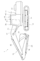
- FIG. 2 is a side view of the work machine 1.
- the work machine 1 includes a vehicle body 11 and a work machine 12.
- the vehicle body 11 includes a revolving unit 13 and a traveling unit 14.
- the revolving unit 13 is attached to the traveling unit 14 so as to be revolvable.
- a cab 15 is arranged on the revolving superstructure 13. However, the cab 15 may be omitted.
- the traveling body 14 includes a crawler belt 16.
- the work machine 1 travels when the crawler belt 16 is driven by a driving force of an engine 24 described later.
- Work machine 12 is attached to the front of vehicle body 11.
- Work implement 12 includes boom 17, arm 18, and bucket 19.
- the boom 17 is attached to the revolving unit 13 so as to be operable in a vertical direction.
- the arm 18 is operably attached to the boom 17.
- the bucket 19 is operatively attached to the arm 18.
- Work implement 12 includes a boom cylinder 21, an arm cylinder 22, and a bucket cylinder 23.
- the boom cylinder 21, the arm cylinder 22, and the bucket cylinder 23 are hydraulic cylinders, and are driven by hydraulic oil from a hydraulic pump 25 described later.
- the boom cylinder 21 operates the boom 17.
- the arm cylinder 22 operates the arm 18.
- the bucket cylinder 23 operates the bucket 19.
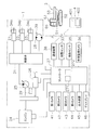
- FIG. 3 is a block diagram showing a configuration of a control system of the work machine 1.
- the work machine 1 includes an engine 24, a hydraulic pump 25, a power transmission device 26, and a controller 27.
- the engine 24 is controlled by a command signal from the controller 27.
- the hydraulic pump 25 is driven by the engine 24 and discharges hydraulic oil.
- the hydraulic oil discharged from the hydraulic pump 25 is supplied to the boom cylinder 21, the arm cylinder 22, and the bucket cylinder 23.
- the work machine 1 includes the swing motor 28.
- the turning motor 28 is a hydraulic motor, and is driven by hydraulic oil from a hydraulic pump 25.
- the swing motor 28 swings the swing body 13. Although one hydraulic pump 25 is shown in FIG. 2, a plurality of hydraulic pumps may be provided.
- the hydraulic pump 25 is a variable displacement pump.
- a pump control device 29 is connected to the hydraulic pump 25.
- the pump control device 29 controls the tilt angle of the hydraulic pump 25.
- the pump control device 29 includes, for example, an electromagnetic valve, and is controlled by a command signal from the controller 27.
- the controller 27 controls the displacement of the hydraulic pump 25 by controlling the pump control device 29.
- the hydraulic pump 25, the cylinders 21-23 and the turning motor 28 are connected by a hydraulic circuit via a control valve 31.
- the control valve 31 is controlled by a command signal from the controller 27.
- the control valve 31 controls the flow rate of hydraulic oil supplied from the hydraulic pump 25 to the cylinders 21 to 23 and the swing motor 28.
- the controller 27 controls the operation of the work implement 12 by controlling the control valve 31. Further, the controller 27 controls the turning of the revolving body 13 by controlling the control valve 31.
- the power transmission device 26 transmits the driving force of the engine 24 to the traveling body 14.
- the power transmission device 26 may be, for example, a torque converter or a transmission having a plurality of transmission gears.
- the power transmission device 26 may be another type of transmission such as HST (Hydro Static ⁇ Transmission) or HMT (Hydraulic Mechanical Transmission).
- the controller 27 is programmed to control the work machine 1 based on the acquired data.
- the controller 27 causes the work machine 1 to travel by controlling the engine 24, the traveling body 14, and the power transmission device 26.
- the controller 27 operates the work implement 12 by controlling the engine 24, the hydraulic pump 25, and the control valve 31.
- the controller 27 includes a processor 271 such as a CPU or a GPU, and a memory 272.
- the processor 271 performs a process for automatically controlling the work machine 1.
- the memory 272 may include a volatile memory such as a RAM or a non-volatile memory such as a ROM.
- the memory 272 stores data and programs for automatic control of the work machine 1.
- the work machine 1 includes a position sensor 33, work machine sensors 34a to 34c, and a turning angle sensor 39.
- the position sensor 33 detects the position of the work machine 1 and outputs position data indicating the position of the work machine 1.
- the position sensor 33 includes a GNSS (Global Navigation Satellite System) receiver.
- the GNSS receiver is, for example, a receiver for GPS (Global Positioning System).
- Work machine sensors 34a-34c detect the posture of work machine 12 and output posture data indicating the posture of work machine 12.
- the work implement sensors 34a to 34c are stroke sensors that detect the stroke amount of the cylinders 21 to 23, for example.
- the posture data of the work machine 12 includes the stroke amounts of the cylinders 21-23.
- the work implement sensors 34a to 34c may be other sensors such as a sensor that detects the rotation angle of each of the boom 17, the arm 18, and the bucket 19.
- the turning angle sensor 39 detects a turning angle of the turning body 13 with respect to the traveling body 14 and outputs turning angle data indicating the turning angle.
- the controller 27 is communicably connected to the position sensor 33, the work equipment sensors 34a to 34c, and the turning angle sensor 39 by wire or wirelessly.
- the controller 27 receives the position data of the work machine 1, the posture data of the work machine 12, and the turning angle data from the position sensor 33, the working machine sensors 34a to 34c, and the turning angle sensor 39, respectively.
- the controller 27 calculates the cutting edge position of the bucket 19 from the position data, the posture data, and the turning angle data.
- the position data of the work machine 1 indicates global coordinates of the position sensor 33.
- the controller 27 calculates the global coordinates of the cutting edge position of the bucket 19 from the global coordinates of the position sensor 33 based on the posture data and the turning angle data of the work implement 12.
- the Work machine 1 includes a terrain sensor 35.
- the terrain sensor 35 measures the terrain around the work machine 1 and outputs terrain data indicating the terrain measured by the terrain sensor 35.
- the terrain sensor 35 is attached to the side of the revolving unit 13.
- the terrain sensor 35 measures the terrain located on the side of the revolving superstructure 13.
- the terrain sensor 35 is, for example, a lidar (LIDAR: Laser Imaging Detection and Ranging).
- the lidar measures the distance to a plurality of measurement points on the terrain by irradiating a laser and measuring the reflected light.
- the terrain data indicates the position of each measurement point with respect to the work machine 1.
- the work machine 1 includes a work monitoring camera 36 and a plurality of peripheral monitoring cameras 41-44. As shown in FIG. 2, the work monitoring camera 36 is attached to the revolving unit 13 so as to face forward of the revolving unit 13. The work monitoring camera 36 photographs the front of the revolving superstructure 13. The work monitoring camera 36 is a stereo camera. The work monitoring camera 36 outputs work image data indicating an image captured by the work monitoring camera 36.
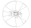
- FIG. 4 is a plan view of the work machine 1 and its surroundings. As shown in FIG. 4, the surrounding monitoring cameras 41 to 44 respectively capture images in different directions.
- the peripheral monitoring cameras 41-44 are monocular cameras.
- the peripheral monitoring cameras 41-44 include a first camera 41, a second camera 42, a third camera 43, and a fourth camera 44.
- the first camera 41 is attached to one side of the revolving unit 13.
- the second camera 42 is attached to the other side of the revolving unit 13.
- the first camera 41 photographs one side of the work machine 1.
- the second camera 42 photographs the other side of the work machine 1.
- the third camera 43 and the fourth camera 44 are attached to the rear part of the revolving unit 13.
- the third camera 43 and the fourth camera 44 photograph the rear of the work machine 1.
- the first camera 41 outputs first image data indicating a first captured image captured by the first camera 41.
- the second camera 42 outputs second image data indicating a second captured image captured by the second camera 42.
- the third camera 43 outputs third image data indicating a third captured image captured by the third camera 43.
- the fourth camera 44 outputs fourth image data indicating a fourth captured image captured by the fourth camera 44.
- the controller 27 is communicably connected to the work monitoring camera 36 and the surrounding monitoring cameras 41-44 by wire or wirelessly.
- the controller 27 receives work image data from the work monitoring camera 36.
- the controller 27 receives the first to fourth image data from the peripheral monitoring cameras 41-44.
- the number of the peripheral monitoring cameras 41-44 is not limited to four and may be three or less, or five or more.
- Work machine 1 includes communication device 38.
- the communication device 38 performs data communication with a device external to the work machine 1.
- the communication device 38 communicates with a remote computer device 4 outside the work machine 1.
- the remote computer device 4 may be located at a work site. Alternatively, the remote computer device 4 may be located in a management center remote from the work site.
- the remote computer device 4 includes a display 401 and an input device 402.
- the display 401 displays an image related to the work machine 1.
- the display 401 displays an image corresponding to a signal received from the controller 27 via the communication device 38.
- the input device 402 is operated by an operator.
- Input device 402 may include, for example, a touch panel, or may include hardware keys.
- the remote computer device 4 transmits a signal indicating a command input by the input device 402 to the controller 27 via the communication device 38.
- the transport vehicle 2 includes a vehicle body 51, a traveling body 52, and a carrier 53.
- the vehicle body 51 is supported by the traveling body 52.
- the traveling body 52 When the traveling body 52 is driven, the transport vehicle 2 travels.
- the carrier 53 is supported by the vehicle body 51.
- the transport vehicle 2 includes a position sensor 63 and a communication device 66.
- the position sensor 63 includes a GNSS receiver, for example, like the position sensor 33 of the work machine 1.
- the position sensor 63 detects the position of the transport vehicle 2.
- the communication device 38 of the work machine 1 performs data communication with the communication device 66 of the transport vehicle 2.
- the controller 27 of the work machine 1 receives the position data of the transport vehicle 2 via the communication devices 38 and 66.
- FIG. 5 is a flowchart showing processing in the automatic control mode.
- the controller 27 When the controller 27 receives the command to start the automatic control mode, the controller 27 starts the engine 24 of the work machine 1 and executes the processing shown in FIG.
- the command to start the automatic control mode is output from the remote computer device 4 when, for example, the operator operates the input device 402 of the remote computer device 4 described above.
- the controller 27 receives the start command via the communication device 38.
- step S101 the controller 27 acquires the position of the work machine 1.
- the controller 27 acquires the position data of the work machine 1, the posture data of the work machine 12, and the turning angle data from the position sensor 33, the working machine sensors 34a to 34c, and the turning angle sensor 39, respectively.
- the controller 27 calculates the cutting edge position of the bucket 19 from the position data, the posture data, and the turning angle data.
- step S102 the controller 27 acquires image data.
- the controller 27 acquires work image data indicating an image in front of the revolving unit 13 from the work monitoring camera 36. Further, the controller 27 acquires first to fourth image data indicating images on both sides and the rear of the revolving unit 13 from the surrounding monitoring cameras 41-44.
- the work monitoring camera 36 and the peripheral monitoring cameras 41-44 always take pictures at least during execution of the automatic control mode, and generate work image data and first to fourth image data.
- the controller 27 acquires the work image data and the first to fourth image data in real time from the work monitoring camera 36 and the peripheral monitoring cameras 41 to 44 at least during execution of the automatic control mode.
- step S103 the controller 27 executes image processing.
- image processing the presence of a predetermined object around the work machine 1 is detected by image recognition technology based on the work image data and the first to fourth image data.
- step S104 the controller 27 determines whether a person has been detected near the work machine 1. The image processing and the method of detecting a person will be described later. When no person is detected near the work machine 1, the controller 27 executes the processing in the first control mode shown in steps S105 to S109.
- step S105 the controller 27 determines whether the transport vehicle 2 has been detected.
- the controller 27 detects whether or not the transport vehicle 2 has reached a predetermined loading position P2 from the work image data by using the image recognition technology. Alternatively, the controller 27 detects whether or not the transport vehicle 2 has reached the predetermined loading position P2 based on the position data received from the transport vehicle 2.
- the process proceeds to step S106.
- step S106 the controller 27 performs automatic excavation.
- the controller 27 controls the work machine 1 so that the work machine 12 performs excavation at the predetermined excavation position P1.
- the controller 27 measures the terrain at the digging position P1 by the terrain sensor 35.
- the controller 27 adjusts the digging position of the work implement 12 according to the terrain at the digging position P1 measured by the terrain sensor 35.
- the controller 27 determines a target excavation route according to the terrain at the excavation position P1 measured by the terrain sensor 35.
- the controller 27 controls the work implement 12 so that the cutting edge of the work implement 12 moves according to the target excavation path.
- step S107 the controller 27 performs automatic loading.
- the controller 27 controls the work machine 1 so that the swing body 13 is swung from the excavation position P1 toward the loading position P2, and the work implement 12 is discharged from the work implement 12 at the loading position P2.
- the excavated material is loaded on the bed 53 of the transport vehicle 2 stopped at the loading position P2.
- step S108 the controller 27 determines whether the loading is completed.
- the controller 27 acquires the weight of the material loaded on the loading platform 53, for example, and determines that the loading has been completed when the weight of the material reaches the allowable weight.
- step S108 determines in step S108 that loading is not completed, the process returns to step S106. Then, the processing of step S106 and step S107 is repeated. Thereby, the excavation of the material and the loading on the transport vehicle 2 are repeated.
- step S109 the controller 27 sends a command to the transport vehicle 2 to leave the loading position P2.
- the transport vehicle 2 moves from the loading position P2 toward the dump position P3.
- step S110 the controller 27 determines whether an end command has been received.
- the controller 27 stops the automatic control mode.
- the controller 27 is output from the remote computer device 4 when the operator operates the input device 402 of the remote computer device 4 described above.
- the controller 27 receives the end command via the communication device 38.
- controller 27 executes a process in the second control mode shown in step S111. Specifically, in step S111, the controller 27 causes the output device 45 to output an alarm. As shown in FIG. 2, in the present embodiment, the output device 45 is a warning light provided on the work machine 1. The controller 27 turns on a warning light when a person is detected near the work machine 1. Note that the output device 45 may be a speaker. The controller 27 may emit a warning sound from a speaker when a person is detected near the work machine 1.
- the controller 27 determines in real time whether or not a person near the work machine 1 has been detected, at least during execution of the automatic control mode. Therefore, when a person is detected near the work machine 1 during the execution of the first control mode, the controller 27 may output an alarm to the output device 45 while executing the process in the first control mode. . Alternatively, the controller 27 may stop the processing in the first control mode and cause the output device 45 to output an alarm.
- the controller 27 detects the presence of a specific object in the images indicated by the work image data and the first to fourth image data by an image recognition technology using AI (Artificial Intelligence).
- Specific objects include people.
- the specific object is not limited to a person, and may include the transport vehicle 2 or another work machine such as a bulldozer.
- the controller 27 identifies a person and another specific object by using an image recognition technique.
- the controller 27 includes the learned object detection model 111.
- the object detection model 111 is mounted on the controller 27.
- the object detection model 111 is an artificial intelligence model for image analysis.
- the object detection model 111 analyzes the input image data D11 and determines whether a specific object is included in the image indicated by the image data.
- the image data D11 includes the above-described work image data and the first to fourth image data.
- the object detection model 111 determines the class of the specific object in the image, the coordinates of the specific object in the image, and the distance to the specific object. Output.
- a particular object class is a particular object type and includes people.
- the specific object class may include a type other than a person, such as the transport vehicle 2 or a bulldozer.
- the object detection model 111 includes the neural network 120 shown in FIG.
- the object detection model 111 includes a deep neural network such as a convolutional neural network (CNN).
- CNN convolutional neural network
- the neural network 120 includes an input layer 121, an intermediate layer 122 (hidden layer), and an output layer 123.
- Each of the layers 121, 122, and 123 includes one or a plurality of neurons. Neurons in adjacent layers are connected to each other, and a weight (connection weight) is set for each connection. The number of connected neurons may be set as appropriate.
- a threshold is set for each neuron, and the output value of each neuron is determined depending on whether or not the sum of the product of the input value to each neuron and the weight exceeds the threshold.
- the image data D11 is input to the input layer 121.
- Output values indicating the class of the specific object detected in the image, the coordinates of the specific object in the image, and the distance to the specific object are output to the output layer 123.
- the object detection model 111 outputs output values indicating a class of the specific object detected in the image, coordinates of the specific object in the image, and a distance to the specific object.
- the learned parameters of the object detection model 111 obtained by the learning are stored in the controller 27.
- the learned parameters include, for example, the number of layers of the neural network 120, the number of neurons in each layer, the connection relationship between neurons, the weight of connection between neurons, and the threshold value of each neuron.
- FIG. 8 is a flowchart showing a process for detecting a person near work machine 1.
- the controller 27 detects a person in the image.
- the controller 27 performs the image analysis using the object detection model 111 on each of the image indicated by the work image data and the plurality of captured images of the work machine 1 indicated by the first to fourth image data. And detect people.
- FIG. 9 is a diagram illustrating an example of a first captured image captured by the first camera 41.
- the controller 27 recognizes and detects the plurality of persons H1-H3 in the image, respectively.
- the controller 27 detects the coordinates in the image of each of the plurality of persons H1-H3 in the image and the distance from the work machine 1.
- the coordinates of the person H1-H3 in the image indicate the position in the image of the frame indicating the person H1-H3.
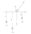
- FIG. 10 is a plan view showing the positions of the people H1-H3 detected in the image shown in FIG.
- the controller 27 acquires the distances L1-L3 from the work machine 1 to the persons H1-H3 included in the image.
- step S202 the controller 27 determines the distance parameter D.
- the controller 27 determines the distance to the person included in the image as the distance parameter D.
- the controller 27 selects the shortest distance among the distances to the plurality of persons included in the image as the distance parameter D.
- the controller 27 selects, as the distance parameter D, the shortest distance L3 among the distances L1-L3 to a plurality of persons H1-H3 included in the image. Note that the controller 27 detects a person included in the image at every predetermined sampling time, and acquires a distance to the person. Further, the controller 27 determines the distance parameter D every predetermined sampling time.
- the controller 27 determines the distance parameter D for each of the first to fourth captured images. For example, when a plurality of people are detected in the first captured image, the shortest distance among the plurality of people included in the first captured image is determined as the distance parameter D in the first captured image. When a plurality of persons are detected in the second captured image, the shortest distance among the distances to the plurality of persons included in the second captured image is determined as the distance parameter D in the second captured image. When a plurality of persons are detected in the third captured image, the shortest distance among the distances to the plurality of persons included in the third captured image is determined as the distance parameter D in the third captured image. When a plurality of persons are detected in the fourth captured image, the shortest distance among the distances to the plurality of persons included in the fourth captured image is determined as the distance parameter D in the fourth captured image.
- step S203 the controller 27 determines whether the distance parameter D is smaller than a predetermined distance threshold A.
- the controller 27 determines in step S204 that a person has been detected near the work machine 1.
- the controller 27 determines whether at least one of the distance parameters D of the plurality of captured images is smaller than a predetermined distance threshold A in step S203. Then, when at least one of the distance parameters D of the plurality of captured images is smaller than the predetermined distance threshold A, the controller 27 determines in step S204 that a person has been detected near the work machine 1.
- the controller 27 when the controller 27 detects a person near the work machine 1, the controller 27 outputs an alarm from the output device 45. Therefore, the controller 27 outputs an alarm from the output device 45 when a person is detected in a range from the work machine 1 to the predetermined distance threshold A in at least one of the plurality of captured images. Further, the controller 27 stops the alarm from the output device 45 when the detection of the person from the work machine 1 in a range up to the predetermined distance threshold A is stopped in all of the images indicated by the work image data and the photographed images. I do.
- the controller 27 detects the presence of a person from the captured image of the work machine 1 by image analysis using the learned object detection model 111, The distance from the work machine 1 to a person is acquired. The controller 27 controls the work machine 1 based on the distance to the detected person, so that the work by the work machine 1 can be automatically performed while considering the surrounding environment.
- the object detection model 111 learns a specific object and the distance to the object, if a single image is input to the object detection model 11, the specific object included in the single image, the distance, Can be obtained. Therefore, the distance can be obtained from a single image without using information such as the shape information of the photographed terrain and the size of the photographed object.
- FIG. 11 is a diagram showing a learning system 200 for learning the object detection model 111.
- the learning system 200 includes a learning data generation module 211 and a learning module 212.
- the learning data generation module 211 generates learning data D22 from the image data D21.
- the learning module 212 learns the object detection model 111 using the learning data D22, and optimizes the parameters of the object detection model 111.
- the learning system 200 acquires the optimized parameter as the learned parameter D23.
- the learning data generation module 211 and the learning module 212 are mounted on a computer.
- the learning data generation module 211 and the learning module 212 may be implemented on a single computer. Alternatively, the learning data generation module 211 and the learning module 212 may be distributed and implemented on a plurality of computers.
- the learning data generation module 211 assigns class information, position information, and distance information of a specific object to an image within a frame specified in the image indicated by the image data D21.
- the class information indicates a class of a specific object existing in the image.
- the position information is the position of a specific object in the image, and indicates the coordinates of the frame in the image.
- the distance information indicates a distance to a specific object.
- Class information may be assigned by manual input by humans.
- the position information may be assigned from the image data D21 by an operation of the learning data generation module 211.
- the distance information may be assigned by the calculation of the learning data generation module 211 from the image data D21 acquired by the stereo camera. Alternatively, the distance information may be assigned by manual input by a human.
- the learning data generation module 211 generates the learning data D22 by repeating the above assignment for a plurality of images.
- the learning module 212 learns the object detection model 111 based on the learning data D22.
- the learning module 212 uses the image included in the learning data D22 as input data, and uses the class of a specific object in the working image, the coordinates of the specific object in the image, and the distance to the specific object as teacher data to perform object detection. Learning of the model 111 is performed.
- the computer 202 uses the pixel values of the image as inputs to the input layer 121 to perform a calculation process in the forward propagation direction of the neural network 120.
- the learning module 212 obtains an output value output from the output layer 123 of the neural network 120.
- the learning module 212 calculates an error between an output value output from the output layer 123 and a correct output value indicated by the teacher data.
- the learning module 212 calculates the weight of the connection between the neurons and the error of the threshold of each neuron by back propagation from the error of the calculated output value.
- the learning module 212 updates the weight of the connection between the neurons and the threshold value of each neuron based on the calculated errors.
- the learning module 212 repeats the above processing until the output values from the object detection model 111 match the correct output values indicated by the teacher data for a plurality of images. Thereby, the parameters of the object detection model 111 are optimized, and the object detection model 111 can be learned.
- the initial values of various parameters of the object detection model 111 may be given by a template. Alternatively, the initial values of the parameters may be provided manually by human input.
- the learning module 212 may prepare an initial value of the parameter based on the learned parameter D23 of the object detection model 111 to be re-learned.
- the learning system 200 may update the learned parameter D23 by periodically executing the learning of the object detection model 111 described above.
- the learning system 200 may transfer the updated learned parameter D23 to the controller 27.
- the controller 27 may update the parameters of the object detection model 111 with the transferred learned parameters D23.
- the work machine 1 is not limited to a hydraulic excavator, and may be another machine such as a wheel loader or a motor grader.
- the configuration of the work machine 1 is not limited to the above-described embodiment, and may be changed.
- Work machine 1 may be a vehicle driven by an electric motor.
- the traveling unit 14 and / or the revolving unit 13 may be driven by an electric motor.
- the configuration of the work machine 12 may be changed.
- the work machine 12 is not limited to the bucket 19 and may include other loading attachments such as a grapple, a fork, and a lifting magnet.
- the transport vehicle 2 may be a vehicle other than the dump truck.
- the configuration of the transport vehicle 2 is not limited to the above-described embodiment, and may be changed.
- the transport vehicle 2 may be driven by automatic control. Alternatively, the transport vehicle 2 may be driven manually by an operator.
- the transport vehicle 2 may be omitted. That is, the work performed by the work machine 1 may be work other than the work cooperating with the transport vehicle 2.
- the terrain sensor 35 may be arranged at a portion other than the side of the revolving unit 13.
- the terrain sensor 35 is not limited to a lidar, but may be another sensing device such as a radar.
- the terrain sensor 35 may be a camera, and the controller 27 may recognize the terrain by analyzing an image captured by the camera.
- the work monitoring camera 36 may be arranged at a part other than the front part of the revolving unit 13.
- the peripheral monitoring cameras 41-44 may be arranged at portions other than the both sides and the rear portion of the revolving unit 13.
- the controller 27 is not limited to one, and may be divided into a plurality of controllers 27.
- the processing executed by the controller 27 may be executed by being distributed to a plurality of controllers 27. In that case, some of the plurality of controllers 27 may be arranged outside the work machine 1.
- the processing in the automatic control mode executed by the controller 27 is not limited to the above-described embodiment, and may be changed.
- the predetermined operation performed by the work machine 1 in the first control mode is not limited to excavation and loading, and may be another operation.
- the controller 27 may stop the work machine 1.
- the controller 27 may limit the operation of the work machine 1 in the second control mode more than the operation in the first control mode.
- the controller 27 may reduce the turning speed of the work machine 1.
- the controller 27 may limit the turning range of the work machine 1.
- the controller 27 may reduce the traveling speed of the work machine 1.
- the controller 27 may limit the traveling range of the work machine 1.
- the controller 27 determines the distance parameter D at every predetermined sampling time.
- the controller 27 may correct the current distance parameter D so that the difference becomes smaller. For example, the controller 27 may determine the average value of the current distance parameter D and the previous distance parameter D as the current distance parameter D. Alternatively, the controller 27 may ignore the current distance parameter D and determine the same value as the previous distance parameter D as the current distance parameter D.
- FIG. 12 is a block diagram showing a configuration of a control system of work machine 1 according to a modification.
- the control system of the work machine 1 may include a display 46.
- the display 46 is, for example, an LCD (liquid crystal display), an organic EL (electroluminescence) display, or a CRT (cathode ray tube) display.
- the controller 27 may add the class and the distance of the specific object detected from the captured image to the captured image and display the same on the display 46.
- the display 46 may be mounted on the work machine 1. Alternatively, the display 46 may be arranged outside the work machine 1.
Landscapes
- Engineering & Computer Science (AREA)
- General Engineering & Computer Science (AREA)
- Mechanical Engineering (AREA)
- Mining & Mineral Resources (AREA)
- Theoretical Computer Science (AREA)
- Civil Engineering (AREA)
- Structural Engineering (AREA)
- Physics & Mathematics (AREA)
- General Physics & Mathematics (AREA)
- Life Sciences & Earth Sciences (AREA)
- General Health & Medical Sciences (AREA)
- Software Systems (AREA)
- Biophysics (AREA)
- Computational Linguistics (AREA)
- Data Mining & Analysis (AREA)
- Evolutionary Computation (AREA)
- Artificial Intelligence (AREA)
- Molecular Biology (AREA)
- Computing Systems (AREA)
- Health & Medical Sciences (AREA)
- Mathematical Physics (AREA)
- Biomedical Technology (AREA)
- Signal Processing (AREA)
- Multimedia (AREA)
- Computer Vision & Pattern Recognition (AREA)
- General Life Sciences & Earth Sciences (AREA)
- Paleontology (AREA)
- Operation Control Of Excavators (AREA)
- Component Parts Of Construction Machinery (AREA)
- Closed-Circuit Television Systems (AREA)
- Studio Devices (AREA)
- Image Analysis (AREA)
Abstract
プロセッサは、カメラが撮影した撮影画像を示す画像データを取得する。プロセッサは、物体検出モデルを用いた画像解析により、画像データから、撮影画像内に存在する特定の物体と、作業機械から特定の物体までの距離とを取得する。物体検出モデルは、特定の物体の画像と、特定の物体までの距離とを学習済みである。プロセッサは、撮影画像において特定の物体を検出したときには、作業機械から特定の物体までの距離に基づいて作業機械を制御する。
Description
本発明は、作業機械の制御システム及び方法に関する。
作業機械による作業を自動制御によって行う技術が知られている。例えば、特許文献1では、掘削位置と排土位置とが作業機械のコントローラに予め教示されている。コントローラは、掘削位置で掘削を行い、掘削位置から排土位置に向けて作業機械を旋回させ、排土位置で排土するように作業機械を制御する。
上記のように、作業機械による作業を自動制御によって行う場合、作業機械は自動で動作する。このような自動動作は、周囲の環境を考慮しつつ行うことが好ましい。本発明は、周囲の環境を考慮しつつ、作業機械による作業を自動で行うことが可能な技術を提供する。
第1の態様に係るシステムは、作業機械と、作業機械の周辺を撮影するカメラと、プロセッサとを備える。プロセッサは、カメラが撮影した撮影画像を示す画像データを取得する。プロセッサは、物体検出モデルを用いた画像解析により、画像データから、撮影画像内に存在する特定の物体と、作業機械から特定の物体までの距離とを取得する。物体検出モデルは、特定の物体の画像と、特定の物体までの距離とを学習済みである。プロセッサは、撮影画像において特定の物体を検出したときには、作業機械から特定の物体までの距離から得られる距離に基づいて作業機械を制御する。
第2の態様に係る方法は、作業機械を制御するためにプロセッサによって実行される方法である。当該方法は、以下の処理を備える。第1の処理は、作業機械の周辺を撮影した撮影画像を示す画像データを取得することである。第2の処理は、物体検出モデルを用いた画像解析により、画像データから、撮影画像内に存在する特定の物体と、作業機械から特定の物体までの距離とを取得することである。物体検出モデルは、特定の物体の画像と、特定の物体までの距離とを学習済みである。第3の処理は、撮影画像において特定の物体を検出したときに、作業機械から特定の物体までの距離に基づいて作業機械を制御することである。
第3の態様に係るシステムは、作業機械と、作業機械の周辺を撮影するカメラと、ディスプレイと、プロセッサとを備える。プロセッサは、カメラによって撮影された撮影画像を示す画像データを取得する。プロセッサは、物体検出モデルを用いた画像解析により、画像データから、撮影画像内に存在する特定の物体と、作業機械から特定の物体までの距離とを取得する。物体検出モデルは、特定の物体の画像と、特定の物体までの距離とを学習済みである。プロセッサは、特定の物体を示す情報と、距離を示す情報とを撮影画像に付加してディスプレイに表示させる。
第4の態様に係る学習データは、物体検出モデルを学習させるための学習データであって、作業機械付近の画像を示す画像データと、画像に存在する特定の物体のクラス情報と、画像における特定の物体の位置情報と、特定の物体に関する距離情報とを備える。
第5の態様に係る方法は、物体検出モデルの製造方法であって、以下の処理を備える。第1の処理は、学習データを取得することである。学習データは、作業機械付近の画像を示す画像データと、画像に存在する特定の物体のクラス情報と、画像における特定の物体の位置情報と、特定の物体に関する距離情報とを含む。第2の処理は、学習データによりモデルを学習させることである。
第6の態様に係る方法は、コンピュータによって実行される方法であって、以下の処理を備える。第1の処理は、作業機械付近の画像を取得することである。第2の処理は、物体検出モデルを用いた画像解析により、撮影画像内に存在する特定の物体と、作業機械から特定の物体までの距離と検出することである。物体検出モデルは、特定の物体の画像と、特定の物体までの距離とを学習済みである。
本発明では、学習済みの物体検出モデルを用いた画像解析によって、作業機械の撮影画像から、特定の物体の存在を検出すると共に、特定の物体までの距離を取得する。そして、特定の物体までの距離から得られる距離パラメータに基づいて作業機械を制御することで、周囲の環境を考慮しつつ、作業機械による作業を自動で行うことができる。
以下、実施形態に係る作業機械1の制御システムについて、図面を参照しながら説明する。図1は、作業機械1が用いられる作業現場の一例を示す平面図である。作業現場には、作業機械1と運搬車両2とが配置されている。作業機械1は、自動制御により運搬車両2と協働して作業を行う。
本実施形態において、作業機械1は油圧ショベルである。運搬車両2はダンプトラックである。作業機械1は、作業現場内の所定の掘削位置P1の横に配置されている。運搬車両2は、作業現場内の所定の積込位置P2と所定のダンプ位置P3との間を走行して往復する。作業機械1は、自動制御により、掘削位置P1を掘削して、土砂等の素材を、積込位置P2に停車している運搬車両2に積み込む。素材を積み込まれた運搬車両2は、ダンプ位置P3まで走行し、ダンプ位置P3に素材を降ろす。ダンプ位置P3には、ブルドーザなどの他の作業機械3が配置されており、ダンプ位置P3に降ろされた素材を敷き広げる。素材を降ろした運搬車両2は積込位置P2まで走行し、作業機械1は、積込位置P2に停車した運搬車両2に再び素材を積み込む。このような作業が繰り返されることで、掘削位置P1の素材がダンプ位置P3に移送される。
図2は、作業機械1の側面図である。図2に示すように、作業機械1は、車両本体11と作業機12とを含む。車両本体11は、旋回体13と走行体14とを含む。旋回体13は、走行体14に対して旋回可能に取り付けられている。旋回体13にはキャブ15が配置されている。ただし、キャブ15は省略されてもよい。走行体14は、履帯16を含む。後述するエンジン24の駆動力によって履帯16が駆動されることで、作業機械1は走行する。
作業機12は、車両本体11の前部に取り付けられている。作業機12は、ブーム17とアーム18とバケット19とを含む。ブーム17は、旋回体13に対して上下方向に動作可能に取り付けられている。アーム18は、ブーム17に対して動作可能に取り付けられている。バケット19は、アーム18に対して動作可能に取り付けられている。作業機12は、ブームシリンダ21と、アームシリンダ22と、バケットシリンダ23とを含む。ブームシリンダ21と、アームシリンダ22と、バケットシリンダ23とは、油圧シリンダであり、後述する油圧ポンプ25からの作動油によって駆動される。ブームシリンダ21は、ブーム17を動作させる。アームシリンダ22は、アーム18を動作させる。バケットシリンダ23は、バケット19を動作させる。
図3は、作業機械1の制御システムの構成を示すブロック図である。図3に示すように、作業機械1は、エンジン24と、油圧ポンプ25と、動力伝達装置26と、コントローラ27とを含む。
エンジン24は、コントローラ27からの指令信号により制御される。油圧ポンプ25は、エンジン24によって駆動され、作動油を吐出する。油圧ポンプ25から吐出された作動油は、ブームシリンダ21と、アームシリンダ22と、バケットシリンダ23とに供給される。
作業機械1は、旋回モータ28を含む。旋回モータ28は、油圧モータであり、油圧ポンプ25からの作動油によって駆動される。旋回モータ28は、旋回体13を旋回させる。なお、図2では、1つの油圧ポンプ25が図示されているが、複数の油圧ポンプが設けられてもよい。
油圧ポンプ25は可変容量ポンプである。油圧ポンプ25にはポンプ制御装置29が接続されている。ポンプ制御装置29は、油圧ポンプ25の傾転角を制御する。ポンプ制御装置29は、例えば電磁弁を含み、コントローラ27からの指令信号により制御される。コントローラ27は、ポンプ制御装置29を制御することで、油圧ポンプ25の容量を制御する。
油圧ポンプ25とシリンダ21-23と旋回モータ28とは、制御弁31を介して油圧回路によって接続されている。制御弁31は、コントローラ27からの指令信号によって制御される。制御弁31は、油圧ポンプ25からシリンダ21-23及び旋回モータ28に供給される作動油の流量を制御する。コントローラ27は、制御弁31を制御することで、作業機12の動作を制御する。また、コントローラ27は、制御弁31を制御することで、旋回体13の旋回を制御する。
動力伝達装置26は、エンジン24の駆動力を走行体14に伝達する。動力伝達装置26は、例えば、トルクコンバーター、或いは複数の変速ギアを有するトランスミッションであってもよい。或いは、動力伝達装置26は、HST(Hydro Static Transmission)、或いはHMT(Hydraulic Mechanical Transmission)などの他の形式のトランスミッションであってもよい。
コントローラ27は、取得したデータに基づいて作業機械1を制御するようにプログラムされている。コントローラ27は、エンジン24と走行体14と動力伝達装置26とを制御することで、作業機械1を走行させる。コントローラ27は、エンジン24と油圧ポンプ25と制御弁31とを制御することで、作業機12を動作させる。
コントローラ27は、CPU或いはGPU等のプロセッサ271と、メモリ272とを含む。プロセッサ271は、作業機械1の自動制御のための処理を行う。メモリ272は、例えばRAMなどの揮発性メモリ、或いはROMなどの不揮発性メモリを含んでもよい。メモリ272は、作業機械1の自動制御のためのデータ及びプログラムを記憶している。
作業機械1は、位置センサ33と、作業機センサ34a-34cと、旋回角度センサ39とを含む。位置センサ33は、作業機械1の位置を検出し、作業機械1の位置を示す位置データを出力する。位置センサ33は、GNSS(Global Navigation Satellite System)レシーバを含む。GNSSレシーバは、例えばGPS(Global Positioning System)用の受信機である。
作業機センサ34a-34cは、作業機12の姿勢を検出し、作業機12の姿勢を示す姿勢データを出力する。作業機センサ34a-34cは、例えばシリンダ21-23のストローク量を検出するストロークセンサである。作業機12の姿勢データは、シリンダ21-23のストローク量を含む。或いは、作業機センサ34a-34cは、ブーム17、アーム18、及びバケット19のそれぞれの回転角度を検出するセンサなどの他のセンサであってもよい。旋回角度センサ39は、走行体14に対する旋回体13の旋回角度を検出し、旋回角度を示す旋回角度データを出力する。
コントローラ27は、位置センサ33、作業機センサ34a-34c、及び旋回角度センサ39と有線或いは無線によって通信可能に接続されている。コントローラ27は、位置センサ33と作業機センサ34a-34cと旋回角度センサ39とから、それぞれ作業機械1の位置データと作業機12の姿勢データと旋回角度データとを受信する。コントローラ27は、位置データと姿勢データと旋回角度データとから、バケット19の刃先位置を算出する。例えば、作業機械1の位置データは、位置センサ33のグローバル座標を示す。コントローラ27は、作業機12の姿勢データと旋回角度データとに基づいて、位置センサ33のグローバル座標からバケット19の刃先位置のグローバル座標を算出する。
作業機械1は、地形センサ35を含む。地形センサ35は、作業機械1の周囲の地形を計測して、地形センサ35が計測した地形を示す地形データを出力する。本実施形態では、地形センサ35は、旋回体13の側部に取り付けられている。地形センサ35は、旋回体13の側方に位置する地形を計測する。地形センサ35は、例えばライダ(LIDAR:Laser Imaging Detection and Ranging)である。ライダは、レーザーを照射して、その反射光を計測することで、地形上の複数の計測点までの距離を測定する。地形データは、作業機械1に対する各計測点の位置を示す。
作業機械1は、作業監視カメラ36と、複数の周辺監視カメラ41-44とを含む。図2に示すように、作業監視カメラ36は、旋回体13の前方に向けて、旋回体13に取り付けられている。作業監視カメラ36は、旋回体13の前方を撮影する。作業監視カメラ36はステレオカメラである。作業監視カメラ36は、作業監視カメラ36が撮影した画像を示す作業画像データを出力する。
複数の周辺監視カメラ41-44は、作業機械1の周辺を撮影する。周辺監視カメラ41-44は、旋回体13に取り付けられている。図4は、作業機械1及びその周囲の平面図である。図4に示すように、周辺監視カメラ41-44は、それぞれ互いに異なる方向を撮影する。周辺監視カメラ41-44は、単眼カメラである。周辺監視カメラ41-44は、第1カメラ41と第2カメラ42と第3カメラ43と第4カメラ44とを含む。
第1カメラ41は、旋回体13の一方の側部に取り付けられている。第2カメラ42は、旋回体13の他方の側部に取り付けられている。第1カメラ41は、作業機械1の一側方を撮影する。第2カメラ42は、作業機械1の他側方を撮影する。第3カメラ43と第4カメラ44とは、旋回体13の後部に取り付けられている。第3カメラ43と第4カメラ44とは、作業機械1の後方を撮影する。
第1カメラ41は、第1カメラ41が撮影した第1撮影画像を示す第1画像データを出力する。第2カメラ42は、第2カメラ42が撮影した第2撮影画像を示す第2画像データを出力する。第3カメラ43は、第3カメラ43が撮影した第3撮影画像を示す第3画像データを出力する。第4カメラ44は、第4カメラ44が撮影した第4撮影画像を示す第4画像データを出力する。
コントローラ27は、作業監視カメラ36及び周辺監視カメラ41-44と有線或いは無線により通信可能に接続されている。コントローラ27は、作業監視カメラ36から作業画像データを受信する。コントローラ27は、周辺監視カメラ41-44から第1~第4画像データを受信する。なお、周辺監視カメラ41-44の数は、4つに限らず3つ以下、或いは5つ以上であってもよい。
作業機械1は、通信装置38を含む。通信装置38は、作業機械1の外部の機器とデータ通信を行う。通信装置38は、作業機械1の外部のリモートコンピュータ機器4と通信を行う。リモートコンピュータ機器4は、作業現場に配置されてもよい。或いは、リモートコンピュータ機器4は、作業現場から離れた管理センタ内に配置されてもよい。リモートコンピュータ機器4は、ディスプレイ401と入力装置402とを含む。
ディスプレイ401は、作業機械1に関する画像を表示する。ディスプレイ401は、コントローラ27から通信装置38を介して受信した信号に応じた画像を表示する。入力装置402は、オペレータによって操作される。入力装置402は、例えばタッチパネルを含んでもよく、或いは、ハードウェアキーを含んでもよい。リモートコンピュータ機器4は、入力装置402によって入力された指令を示す信号を、通信装置38を介してコントローラ27に送信する。
図3に示すように、運搬車両2は、車両本体51と、走行体52と、荷台53とを含む。車両本体51は、走行体52に支持されている。走行体52が駆動されることで、運搬車両2は走行する。荷台53は、車両本体51に支持されている。運搬車両2は、位置センサ63と通信装置66とを含む。位置センサ63は、例えば作業機械1の位置センサ33と同様に、GNSSレシーバを含む。位置センサ63は、運搬車両2の位置を検出する。作業機械1の通信装置38は、運搬車両2の通信装置66とデータ通信を行う。作業機械1のコントローラ27は、通信装置38,66を介して、運搬車両2の位置データを受信する。
次に、作業機械1のコントローラ27によって実行される自動制御モードの処理について説明する。自動制御モードでは、コントローラ27は、作業機械1が所定の作業を自動で行うように、作業機械1を制御する。本実施形態において、所定の作業は、掘削及び積込である。図5は、自動制御モードの処理を示すフローチャートである。
コントローラ27は、自動制御モードの開始指令を受信すると、作業機械1のエンジン24を始動すると共に、図5に示す処理を実行する。自動制御モードの開始指令は、例えばオペレータが上述したリモートコンピュータ機器4の入力装置402を操作することで、リモートコンピュータ機器4から出力される。コントローラ27は、通信装置38を介して開始指令を受信する。
図5に示すように、ステップS101では、コントローラ27は、作業機械1の位置を取得する。ここでは、コントローラ27は、位置センサ33と、作業機センサ34a-34cと、旋回角度センサ39とから、それぞれ作業機械1の位置データと作業機12の姿勢データと旋回角度データとを取得する。コントローラ27は、位置データと姿勢データと旋回角度データとから、バケット19の刃先位置を算出する。
ステップS102では、コントローラ27は、画像データを取得する。ここでは、コントローラ27は、旋回体13の前方の画像を示す作業画像データを作業監視カメラ36から取得する。また、コントローラ27は、旋回体13の両側方及び後方の画像を示す第1~第4画像データを周辺監視カメラ41-44から取得する。なお、作業監視カメラ36と周辺監視カメラ41-44とは、少なくとも自動制御モードの実行中には、常時、撮影を行い、作業画像データと第1~第4画像データとを生成する。コントローラ27は、少なくとも自動制御モードの実行中には、作業監視カメラ36と周辺監視カメラ41-44とから、リアルタイムに作業画像データと第1~第4画像データとを取得する。
ステップS103では、コントローラ27は、画像処理を実行する。画像処理は、作業画像データと第1~第4画像データとに基づいて、画像認識技術により、作業機械1の周囲における所定の物体の存在を検出する。ステップS104では、コントローラ27は、作業機械1の近傍に人が検出されたかを判定する。画像処理、及び、人の検出方法については、後に説明する。作業機械1の近傍に人が検出されないときには、コントローラ27は、ステップS105からステップS109に示す第1制御モードの処理を実行する。
ステップS105では、コントローラ27は、運搬車両2を検出したかを判定する。コントローラ27は、画像認識技術により、作業画像データから運搬車両2が所定の積込位置P2に到達したかを検出する。或いは、コントローラ27は、運搬車両2から受信した位置データにより、運搬車両2が所定の積込位置P2に到達したかを検出する。コントローラ27が運搬車両2を検出したときには、処理はステップS106に進む。
ステップS106では、コントローラ27は、自動掘削を行う。ここでは、コントローラ27は、所定の掘削位置P1で作業機12による掘削を行うように作業機械1を制御する。自動掘削において、コントローラ27は、地形センサ35によって掘削位置P1の地形を計測する。コントローラ27は、地形センサ35が計測した掘削位置P1の地形に応じて、作業機12による掘削位置を調整する。また、コントローラ27は、地形センサ35が計測した掘削位置P1の地形に応じて、目標掘削経路を決定する。コントローラ27は、目標掘削経路に従って作業機12の刃先が移動するように、作業機12を制御する。
ステップS107では、コントローラ27は、自動積込を行う。ここでは、コントローラ27は、掘削位置P1から積込位置P2に向けて旋回体13を旋回させ、積込位置P2で作業機12から排土するように作業機械1を制御する。それにより、積込位置P2に停車している運搬車両2の荷台53に掘削された素材が積み込まれる。
ステップS108では、コントローラ27は、積込が終了したかを判定する。コントローラ27は、例えば荷台53に積み込まれた素材の重量を取得し、当該素材の重量が許容重量に達したときに、積込が終了したと判定する。
ステップS108において、積込が終了していないとコントローラ27が判定したときには、処理はステップS106に戻る。そして、ステップS106とステップS107の処理が繰り返される。それにより、素材の掘削と運搬車両2への積込とが繰り返される。
ステップS108において、積込が終了したとコントローラ27が判定したときには、処理はステップS109に進む。ステップS109では、コントローラ27は、運搬車両2に積込位置P2からの離脱指令を送信する。運搬車両2は、離脱指令を受信すると、積込位置P2からダンプ位置P3に向かって移動する。
ステップS110では、コントローラ27は、終了指令を受信したかを判定する。終了指令を受信したときには、コントローラ27は、自動制御モードを停止させる。例えば、コントローラ27は、オペレータが上述したリモートコンピュータ機器4の入力装置402を操作することで、リモートコンピュータ機器4から出力される。コントローラ27は、通信装置38を介して終了指令を受信する。
ステップS104において、作業機械1の近傍に人が検出されたときには、コントローラ27は、ステップS111に示す第2制御モードの処理を実行する。詳細には、ステップS111では、コントローラ27は、出力装置45に警報を出力させる。図2に示すように、本実施形態では、出力装置45は、作業機械1に設けられた警告灯である。コントローラ27は、作業機械1の近傍に人が検出されたときには、警告灯を点灯する。なお、出力装置45は、スピーカーであってもよい。コントローラ27は、作業機械1の近傍に人が検出されたときには、スピーカーから警告音を発してもよい。
コントローラ27は、少なくとも自動制御モードの実行中には、作業機械1の近傍での人の検出の判断をリアルタイムに行う。従って、コントローラ27は、第1制御モードの実行中に作業機械1の近傍に人が検出されたときには、第1制御モードでの処理を実行しながら、出力装置45に警報を出力させてもよい。或いは、コントローラ27は、第1制御モードの処理を停止して、出力装置45に警報を出力させてもよい。
次に、作業機械1の近傍での人の検出方法について説明する。コントローラ27は、AI(Artificial Intelligence)を用いた画像認識技術により、作業画像データと第1~第4画像データとが示す画像中の特定の物体の存在を検出する。特定の物体は人を含む。特定の物体は、人のみに限らず、運搬車両2、或いはブルドーザなどの他の作業機械を含んでもよい。コントローラ27は、画像認識技術により、人と、他の特定の物体とを識別する。
図6に示すように、コントローラ27は、学習済みの物体検出モデル111を含む。物体検出モデル111は、コントローラ27に実装されている。物体検出モデル111は、画像解析のための人工知能モデルである。物体検出モデル111は、入力された画像データD11を解析して、画像データが示す画像中に特定の物体が含まれているかを判定する。画像データD11は、上述した作業画像データ及び第1~第4画像データを含む。
画像データD11が示す画像中に特定の物体が含まれているときには、物体検出モデル111は、画像中の特定の物体のクラスと、画像における特定の物体の座標と、特定の物体までの距離を出力する。特定の物体のクラスは、特定の物体の種類であり、人を含む。特定の物体のクラスは、運搬車両2或いはブルドーザなど、人以外の種類を含んでもよい。
物体検出モデル111は、図7に示すニューラルネットワーク120を含む。例えば、物体検出モデル111は、畳み込みニューラルネットワーク(CNN)などのディープニューラルネットワークを含む。図7に示すように、ニューラルネットワーク120は、入力層121、中間層122(隠れ層)、及び出力層123を含む。各層121,122,123は、1又は複数のニューロンを備えている。互いに隣接する層のニューロン同士は結合されており、各結合には重み(結合荷重)が設定されている。ニューロンの結合数は、適宜設定されてよい。各ニューロンには閾値が設定されており、各ニューロンへの入力値と重みとの積の和が閾値を超えているか否かによって各ニューロンの出力値が決定される。
入力層121には、画像データD11が入力される。出力層123には、画像において検出された特定の物体のクラスと、画像における特定の物体の座標と、特定の物体までの距離とを示す出力値が出力される。物体検出モデル111は、画像データD11が入力されると、画像において検出された特定の物体のクラスと、画像における特定の物体の座標と、特定の物体までの距離とを示す出力値を出力するように学習済みである。学習によって得られた物体検出モデル111の学習済みパラメータは、コントローラ27に記憶されている。学習済みパラメータは、例えば、ニューラルネットワーク120の層数、各層におけるニューロンの個数、ニューロン同士の結合関係、各ニューロン間の結合の重み、及び各ニューロンの閾値を含む。
図8は、作業機械1の近傍での人を検出するための処理を示すフローチャートである。図8に示すように、ステップS201では、コントローラ27は、画像内の人を検出する。コントローラ27は、上述したように、物体検出モデル111を用いた画像解析により、作業画像データが示す画像と、第1~第4画像データが示す作業機械1の複数の撮影画像とのそれぞれに対して、人を検出する。
図9は、第1カメラ41によって撮影された第1撮影画像の一例を示す図である。図9に示すように、画像に複数の人H1-H3が含まれるときには、コントローラ27は、画像中の複数の人H1-H3をそれぞれ認識して検出する。コントローラ27は、画像中の複数の人H1-H3のそれぞれの画像内における座標と、作業機械1からの距離とを検出する。画像中の人H1-H3の座標は、人H1-H3を示す枠の画像内での位置を示す。例えば、図10は、図9に示す画像において検出された人H1-H3の位置を示す平面図である。コントローラ27は、作業機械1から、画像中に含まれる人H1-H3までの距離L1-L3を取得する。
ステップS202では、コントローラ27は、距離パラメータDを決定する。コントローラ27は、画像中に人が一人だけ含まれているときには、画像中に含まれる当該人までの距離を距離パラメータDとして決定する。コントローラ27は、画像中に複数の人が含まれているときには、画像中に含まれる複数の人までの距離のうち最短の距離を距離パラメータDとして選択する。
例えば、図10に示す例では、コントローラ27は、画像中に含まれる複数の人H1-H3までの距離L1-L3のうち最短の距離L3を距離パラメータDとして選択する。なお、コントローラ27は、所定のサンプリング時間ごとに画像中に含まれる人を検出し、当該人までの距離を取得する。また、コントローラ27は、所定のサンプリング時間ごとに距離パラメータDを決定する。
コントローラ27は、第1~第4撮影画像のそれぞれについて距離パラメータDを決定する。例えば、第1撮影画像において複数の人が検出されたときには、第1撮影画像に含まれる複数の人までの距離のうち最短の距離を第1撮影画像における距離パラメータDとして決定する。第2撮影画像において複数の人が検出されたときには、第2撮影画像に含まれる複数の人までの距離のうち最短の距離を第2撮影画像における距離パラメータDとして決定する。第3撮影画像において複数の人が検出されたときには、第3撮影画像に含まれる複数の人までの距離のうち最短の距離を第3撮影画像における距離パラメータDとして決定する。第4撮影画像において複数の人が検出されたときには、第4撮影画像に含まれる複数の人までの距離のうち最短の距離を第4撮影画像における距離パラメータDとして決定する。
ステップS203では、コントローラ27は、距離パラメータDが所定の距離閾値Aより小さいかを判定する。距離パラメータDが所定の距離閾値Aより小さいときには、コントローラ27は、ステップS204において、作業機械1の近傍に人を検出したと決定する。
コントローラ27は、複数の撮影画像において人が検出されたときには、ステップS203において、複数の撮影画像のそれぞれの距離パラメータDのうち、少なくとも1つが所定の距離閾値Aより小さいかを判定する。そして、複数の撮影画像のそれぞれの距離パラメータDのうち、少なくとも1つが所定の距離閾値Aより小さいときには、コントローラ27は、ステップS204において、作業機械1の近傍に人を検出したと決定する。
上述したように、コントローラ27は、作業機械1の近傍に人を検出したときには、ス出力装置45から警報を出力する。従って、コントローラ27は、複数の撮影画像の少なくとも1つにおいて、作業機械1から所定の距離閾値Aまでの範囲に人を検出したときには、出力装置45から警報を出力する。また、コントローラ27は、作業画像データが示す画像、及び、撮影画像の全てにおいて、作業機械1から所定の距離閾値Aまでの範囲に人を検出しなくなったときには、出力装置45からの警報を停止する。
以上説明した本実施形態に係る作業機械1の制御システムでは、コントローラ27は、学習済みの物体検出モデル111を用いた画像解析によって、作業機械1の撮影画像から、人の存在を検出すると共に、作業機械1から人までの距離を取得する。そして、コントローラ27は、検出した人まで距離に基づいて作業機械1を制御することで、周囲の環境を考慮しつつ、作業機械1による作業を自動で行うことができる。
また、物体検出モデル111は、特定の物体と当該物体までの距離とを学習しているので、単画像を物体検出モデル11に入力すれば、当該単画像に含まれる特定の物体と、距離とを得ることができる。そのため、撮影される地形の形状情報および撮影された物体の大きさ等の情報を利用することなく、単画像から距離を取得することができる。
次に、実施形態に係る分類モデル111の学習方法について説明する。図11は、物体検出モデル111の学習を行う学習システム200を示す図である。学習システム200は、学習データ生成モジュール211と学習モジュール212とを含む。
学習データ生成モジュール211は、画像データD21から学習データD22を生成する。学習モジュール212は、学習データD22を用いて、物体検出モデル111の学習を行い、物体検出モデル111のパラメータを最適化する。学習システム200は、最適化されたパラメータを学習済みパラメータD23として取得する。学習データ生成モジュール211と学習モジュール212とは、コンピュータに実装されている。学習データ生成モジュール211と学習モジュール212とは、単一のコンピュータに実装されてもよい。或いは、学習データ生成モジュール211と学習モジュール212とは、複数のコンピュータに分散して実装されてもよい。
学習データ生成モジュール211は、画像データD21が示す画像において指定された枠内の画像に、特定の物体のクラス情報と位置情報と距離情報とを割り当てる。クラス情報は、画像に存在する特定の物体のクラスを示す。位置情報は、画像における特定の物体の位置であり、画像における枠の座標を示す。距離情報は、特定の物体までの距離を示す。
クラス情報は、人間が手動で入力することで、割り当てられもよい。位置情報は、画像データD21から、学習データ生成モジュール211の演算により割り当てられてもよい。距離情報は、ステレオカメラによって取得された画像データD21から学習データ生成モジュール211の演算により割り当てられてもよい。或いは、距離情報は、人間が手動で入力することで、割り当てられもよい。学習データ生成モジュール211は、複数の画像に対して上記の割り当てを繰り返すことで、学習データD22を生成する。
学習モジュール212は、学習データD22によって物体検出モデル111の学習を行う。学習モジュール212は、学習データD22に含まれる画像を入力データとし、作業画像中の特定の物体のクラスと、画像における特定の物体の座標と、特定の物体までの距離を教師データとして、物体検出モデル111の学習を行う。
例えば、コンピュータ202は、画像の各画素値を入力層121の入力として用いて、ニューラルネットワーク120の順伝播方向の演算処理を行う。これにより、学習モジュール212は、ニューラルネットワーク120の出力層123から出力される出力値を得る。次に、学習モジュール212は、出力層123から出力される出力値と、教師データが示す正しい出力値との誤差を算出する。学習モジュール212は、算出した出力値の誤差から、バックプロパゲーションにより、各ニューロン間の結合の重み、及び、各ニューロンの閾値のそれぞれの誤差を算出する。そして、学習モジュール212は、算出した各誤差に基づいて、各ニューロン間の結合の重み、及び、各ニューロンの閾値の更新を行う。
学習モジュール212は、複数の画像について、物体検出モデル111からの出力値が、教師データが示す正しい出力値と一致するまで、上記の処理を繰り返す。それにより、物体検出モデル111のパラメータが最適化され、物体検出モデル111を学習させることができる。
なお、物体検出モデル111の各種のパラメータの初期値は、テンプレートにより与えられてもよい。或いは、パラメータの初期値は、人間の入力により手動で与えられてもよい。物体検出モデル111の再学習を行うときには、学習モジュール212は、再学習を行う対象となる物体検出モデル111の学習済みパラメータD23に基づいて、パラメータの初期値を用意してもよい。
なお、学習システム200は、上述した物体検出モデル111の学習を定期的に実行することで、学習済みパラメータD23を更新してもよい。学習システム200は、更新した学習済みパラメータD23をコントローラ27に転送してもよい。コントローラ27は、転送された学習済みパラメータD23によって、物体検出モデル111のパラメータを更新してもよい。
以上、本発明の一実施形態について説明したが、本発明は上記実施形態に限定されるものではなく、発明の要旨を逸脱しない範囲で種々の変更が可能である。
作業機械1は、油圧ショベルに限らず、ホイールローダ、或いはモータグレーダ等の他の機械であってもよい。作業機械1の構成は、上記の実施形態のものに限らず、変更されてもよい。作業機械1は、電動モータで駆動される車両であってもよい。例えば、走行体14及び/又は旋回体13は、電動モータで駆動されてもよい。作業機12の構成が変更されてもよい。例えば、作業機12は、バケット19に限らず、グラップル、フォーク、リフティングマグネットなどの他の積込用アタッチメントを含んでもよい。
運搬車両2は、ダンプトラック以外の車両であってもよい。運搬車両2の構成は、上記の実施形態のものに限らず、変更されてもよい。運搬車両2は自動制御により運転されてもよい。或いは、運搬車両2は、オペレータによって手動で運転されてもよい。運搬車両2は、省略されてもよい。すなわち、作業機械1が行う作業は、運搬車両2と協働するもの以外の作業であってもよい。
作業機械1に備えられる各種のセンサの構成は、上記の実施形態のものに限らず、変更されてもよい。例えば、地形センサ35は、旋回体13の側部以外の部分に配置されてもよい。地形センサ35は、ライダに限らず、レーダーなどの他のセンシング装置であってもよい。或いは、地形センサ35はカメラであってもよく、コントローラ27は、カメラが撮影した画像を解析することで、地形を認識してもよい。
作業監視カメラ36は、旋回体13の前部以外の部分に配置されてもよい。周辺監視カメラ41-44は、旋回体13の両側部及び後部以外の部分に配置されてもよい。
コントローラ27は、一体に限らず、複数のコントローラ27に分かれていてもよい。コントローラ27によって実行される処理は、複数のコントローラ27に分散して実行されてもよい。その場合、複数のコントローラ27の一部は、作業機械1の外部に配置されてもよい。
コントローラ27によって実行される自動制御モードの処理は、上述した実施形態のものに限らず、変更されてもよい。第1制御モードにおいて作業機械1が行う所定の作業は、掘削及び積込に限らず、他の作業であってもよい。第2制御モードにおいて、コントローラ27は、作業機械1を停止させてもよい。或いは、コントローラ27は、第2制御モードにおいて、作業機械1の動作を第1制御モードでの動作よりも制限してもよい。例えば、コントローラ27は、作業機械1の旋回速度を低減してもよい。コントローラ27は、作業機械1の旋回範囲を制限してもよい。コントローラ27は、作業機械1の走行速度を低減してもよい。コントローラ27は、作業機械1の走行範囲を制限してもよい。
上述したように、コントローラ27は、所定のサンプリング時間ごとに、距離パラメータDを決定する。コントローラ27は、今回の距離パラメータDと前回の距離パラメータDとの差分が所定の閾値より大きいときには、差分が小さくなるように今回の距離パラメータDを補正してもよい。例えば、コントローラ27は、今回の距離パラメータDと前回の距離パラメータDとの平均値を、今回の距離パラメータDとして決定してもよい。或いは、コントローラ27は、今回の距離パラメータDを無視して、前回の距離パラメータDと同じ値を今回の距離パラメータDとして決定してもよい。
図12は、変形例に係る作業機械1の制御システムの構成を示すブロック図である。図12に示すように、作業機械1の制御システムは、ディスプレイ46を備えてもよい。ディスプレイ46は、例えばLCD(liquid crystal display)、有機EL(electroluminescence)ディスプレイ、或いはCRT(cathode ray tube)ディスプレイなどである。コントローラ27は、撮影画像から検出した特定の物体のクラスと距離とを、撮影画像に付加してディスプレイ46に表示させてもよい。なお、ディスプレイ46は、作業機械1に搭載されてもよい。或いは、ディスプレイ46は、作業機械1の外部に配置されてもよい。
本発明によれば、周囲の環境を考慮しつつ、作業機械による作業を自動で行うことが可能となる。
1 作業機械
41-44 周辺監視カメラ
271 プロセッサ
45 出力装置
46 ディスプレイ
41-44 周辺監視カメラ
271 プロセッサ
45 出力装置
46 ディスプレイ
Claims (22)
- 作業機械と、
前記作業機械の周辺を撮影するカメラと、
プロセッサと、
を備え、
前記プロセッサは、
前記カメラによって撮影された撮影画像を示す画像データを取得し、
特定の物体の画像と、前記特定の物体までの距離とを学習済みの物体検出モデルを用いた画像解析により、前記画像データから、前記撮影画像内に存在する前記特定の物体と、前記作業機械から前記特定の物体までの距離とを取得し、
前記撮影画像において前記特定の物体を検出したときには、前記作業機械から前記特定の物体までの距離に基づいて前記作業機械を制御する、
システム。 - 前記プロセッサは、
前記撮影画像において複数の前記特定の物体を検出したときには、前記作業機械から前記複数の特定の物体のそれぞれまでの距離のうち最短の距離を距離パラメータとして選択し、
前記距離パラメータに基づいて前記作業機械を制御する、
請求項1に記載のシステム。 - 前記プロセッサは、
前記距離パラメータが所定の距離閾値以上であるときには、前記作業機械が所定の作業を自動で行う第1制御モードにて前記作業機械を制御し、
前記距離パラメータが前記所定の距離閾値より小さいときには、前記第1制御モードと異なる第2制御モードにて前記作業機械を制御する、
請求項2に記載のシステム。 - 前記プロセッサは、
前記作業機械の互いに異なる方向の複数の撮影画像を示す複数の画像データを取得し、
前記物体検出モデルを用いた画像解析により、前記複数の撮影画像のそれぞれにおいて前記特定の物体を検出したときには、前記複数の撮影画像のそれぞれに対して前記距離パラメータを決定し、
前記複数の撮影画像のそれぞれの前記距離パラメータのうち少なくとも1つが前記所定の距離閾値より小さいときには、前記第2制御モードにて前記作業機械を制御する、
請求項3に記載のシステム。 - 前記作業機械は、出力装置を含み、
前記プロセッサは、前記第2制御モードにおいて前記出力装置に警報を出力させる、
請求項3又は4に記載のシステム。 - 前記プロセッサは、前記第2制御モードでは、前記第1制御モードよりも前記作業機械の動作を制限する、
請求項3から5のいずれかに記載のシステム。 - 前記プロセッサは、前記第2制御モードでは、前記作業機械を停止させる、
請求項3から6のいずれかに記載のシステム。 - 前記プロセッサは、所定時間ごとに前記距離を取得し、
今回の距離と前回の距離との差分が所定の閾値より大きいときには、前記差分が小さくなるように前記今回の距離を補正する、
請求項1から7のいずれかに記載のシステム。 - 前記カメラは、単眼カメラである、
請求項1から8のいずれかに記載のシステム。 - 前記特定の物体は、人を含む、
請求項1から9のいずれかに記載のシステム。 - 作業機械を制御するためにプロセッサによって実行される方法であって、
前記作業機械の周辺を撮影した撮影画像を示す画像データを取得することと、
特定の物体の画像と、前記特定の物体までの距離とを学習済みの物体検出モデルを用いた画像解析により、前記画像データから、前記撮影画像内に存在する前記特定の物体と、前記作業機械から前記特定の物体までの距離とを取得することと、
前記撮影画像において前記特定の物体を検出したときには、前記作業機械から前記特定の物体までの距離に基づいて前記作業機械を制御すること、
を備える方法。 - 前記撮影画像において複数の前記特定の物体が検出されたときには、前記作業機械から前記複数の特定の物体のそれぞれまでの距離のうち最短の距離を距離パラメータとして選択することと、
前記距離パラメータに基づいて前記作業機械を制御すること、
をさらに備える、
請求項11に記載の方法。 - 前記距離パラメータが所定の距離閾値以上であるときには、前記作業機械が所定の作業を自動で行う第1制御モードにて前記作業機械を制御することと、
前記距離パラメータが前記所定の距離閾値より小さいときには、前記第1制御モードと異なる第2制御モードにて前記作業機械を制御すること、
をさらに備える、
請求項12に記載の方法。 - 前記作業機械の互いに異なる方向の複数の撮影画像を示す複数の画像データを取得することと、
前記物体検出モデルを用いた画像解析により、前記複数の撮影画像のそれぞれにおいて前記特定の物体を検出したときには、前記複数の撮影画像のそれぞれに対して前記距離パラメータを決定することと、
前記複数の撮影画像のそれぞれの前記距離パラメータのうち少なくとも1つが前記所定の距離閾値より小さいときには、前記第2制御モードにて前記作業機械を制御すること、
をさらに備える請求項13に記載の方法。 - 前記作業機械は、出力装置を含み、
前記第2制御モードにて前記作業機械を制御することは、前記出力装置に警報を出力させることを含む、
請求項13又は14に記載の方法。 - 前記第2制御モードにて前記作業機械を制御することは、前記第1制御モードよりも前記作業機械の動作を制限することを含む、
請求項13から15のいずれかに記載の方法。 - 前記第2制御モードにおいて前記作業機械を制御することは、前記作業機械を停止させることを含む、
請求項13から16のいずれかに記載の方法。 - 前記特定の物体は、人を含む、
請求項11から17のいずれかに記載の方法。 - 作業機械と、
前記作業機械の周辺を撮影するカメラと、
ディスプレイと、
プロセッサと、
を備え、
前記プロセッサは、
前記カメラによって撮影された撮影画像を示す画像データを取得し、
特定の物体の画像と、前記特定の物体までの距離とを学習済みの物体検出モデルを用いた画像解析により、前記画像データから、前記撮影画像内に存在する前記特定の物体と、前記作業機械から前記特定の物体までの距離とを取得し、
前記特定の物体を示す情報と、前記距離を示す情報とを前記撮影画像に付加して前記ディスプレイに表示させる、
システム。 - 物体検出モデルを学習させるための学習データであって、
作業機械付近の画像を示す画像データと、
前記画像に存在する特定の物体のクラス情報と、
前記画像における前記特定の物体の位置情報と、
前記特定の物体に関する距離情報と、
を備える学習データ。 - 物体検出モデルの製造方法であって、
作業機械付近の画像を示す画像データと、前記画像に存在する特定の物体のクラス情報と、前記画像における前記特定の物体の位置情報と、前記特定の物体に関する距離情報と、を含む学習データを取得することと、
前記学習データによりモデルを学習させること、
を備える製造方法。 - コンピュータによって実行される方法であって、
作業機械付近の画像を取得することと、
特定の物体の画像と、前記特定の物体までの距離とを学習済みの物体検出モデルを用いた画像解析により、前記撮影画像内に存在する前記特定の物体と、前記作業機械から前記特定の物体までの距離と検出することと、
を備える方法。
Priority Applications (3)
| Application Number | Priority Date | Filing Date | Title |
|---|---|---|---|
| US17/056,136 US12110665B2 (en) | 2018-09-10 | 2019-08-26 | Control system and control method for controlling work machine in accordance with image data |
| DE112019001524.9T DE112019001524T5 (de) | 2018-09-10 | 2019-08-26 | Steuersystem und -verfahren für Arbeitsmaschine |
| CN201980026485.2A CN111989440A (zh) | 2018-09-10 | 2019-08-26 | 作业机械的控制系统及方法 |
Applications Claiming Priority (2)
| Application Number | Priority Date | Filing Date | Title |
|---|---|---|---|
| JP2018169158A JP7160606B2 (ja) | 2018-09-10 | 2018-09-10 | 作業機械の制御システム及び方法 |
| JP2018-169158 | 2018-09-10 |
Publications (1)
| Publication Number | Publication Date |
|---|---|
| WO2020054366A1 true WO2020054366A1 (ja) | 2020-03-19 |
Family
ID=69778497
Family Applications (1)
| Application Number | Title | Priority Date | Filing Date |
|---|---|---|---|
| PCT/JP2019/033244 Ceased WO2020054366A1 (ja) | 2018-09-10 | 2019-08-26 | 作業機械の制御システム及び方法 |
Country Status (5)
| Country | Link |
|---|---|
| US (1) | US12110665B2 (ja) |
| JP (1) | JP7160606B2 (ja) |
| CN (1) | CN111989440A (ja) |
| DE (1) | DE112019001524T5 (ja) |
| WO (1) | WO2020054366A1 (ja) |
Cited By (2)
| Publication number | Priority date | Publication date | Assignee | Title |
|---|---|---|---|---|
| US12305364B2 (en) | 2021-12-22 | 2025-05-20 | Doosan Bobcat North America, Inc. | Control of multiple power machines |
| US12353205B2 (en) | 2021-08-11 | 2025-07-08 | Doosan Bobcat North America, Inc. | Remote control for a power machine |
Families Citing this family (12)
| Publication number | Priority date | Publication date | Assignee | Title |
|---|---|---|---|---|
| JP7553754B2 (ja) * | 2020-08-25 | 2024-09-19 | 公立大学法人会津大学 | 学習プログラム、学習装置及び学習方法 |
| CN112651593B (zh) * | 2020-11-30 | 2023-04-18 | 东北农业大学 | 一种基于北斗系统的农业机组作业参数测试及分析决策系统及方法 |
| IT202100000242A1 (it) | 2021-01-07 | 2022-07-07 | Cnh Ind Italia Spa | Metodo per rilevare una missione di un veicolo da lavoro o agricolo attraverso una rete neurale e un'unità di controllo che implementa il metodo |
| US12060695B2 (en) * | 2021-07-12 | 2024-08-13 | Caterpillar Inc. | Systems and methods for improving machine performance based on machine application identification |
| US12006655B2 (en) * | 2021-08-02 | 2024-06-11 | Deere & Company | Ground engaging tool contact detection system and method |
| GB2610428A (en) * | 2021-09-06 | 2023-03-08 | Bamford Excavators Ltd | A working machine |
| US12110660B2 (en) * | 2022-02-24 | 2024-10-08 | Caterpillar Inc. | Work machine 3D exclusion zone |
| US20230339734A1 (en) * | 2022-04-26 | 2023-10-26 | Deere & Company | Object detection system and method on a work machine |
| US12272087B2 (en) | 2022-06-24 | 2025-04-08 | Caterpillar Inc. | Systems and methods for estimating object weight using camera images |
| CN115143930B (zh) * | 2022-06-27 | 2024-05-24 | 徐州徐工挖掘机械有限公司 | 一种单目摄像头测距方法、系统及挖掘机 |
| JP2024097620A (ja) * | 2023-01-06 | 2024-07-19 | Jrcモビリティ株式会社 | 物標検知装置、物標検知プログラム、物標検知システム及びカメラ距離学習モデル |
| EP4706362A1 (en) * | 2024-09-09 | 2026-03-11 | AGCO International GmbH | Methods of validating anomalies in agricultural fields, and related agricultural vehicles |
Citations (9)
| Publication number | Priority date | Publication date | Assignee | Title |
|---|---|---|---|---|
| JP2007072665A (ja) * | 2005-09-06 | 2007-03-22 | Fujitsu Ten Ltd | 物体判別装置、物体判別方法および物体判別プログラム |
| JP2008009689A (ja) * | 2006-06-29 | 2008-01-17 | Matsushita Electric Ind Co Ltd | 顔登録装置、顔認証装置および顔登録方法 |
| US20090110301A1 (en) * | 2007-10-26 | 2009-04-30 | Sick Ag | Classification of objects as well as recognition of their position and orientation in space |
| JP2016053904A (ja) * | 2014-09-04 | 2016-04-14 | 株式会社日本自動車部品総合研究所 | 車載装置、車載システム |
| JP2017142591A (ja) * | 2016-02-09 | 2017-08-17 | トヨタ自動車株式会社 | 車両用支援システム |
| JP2017158033A (ja) * | 2016-03-01 | 2017-09-07 | 住友重機械工業株式会社 | 作業機械用周辺監視システム |
| JP2018017115A (ja) * | 2017-09-06 | 2018-02-01 | 住友建機株式会社 | ショベル |
| JP2018077190A (ja) * | 2016-11-11 | 2018-05-17 | 株式会社東芝 | 撮像装置及び自動制御システム |
| JP2018147286A (ja) * | 2017-03-07 | 2018-09-20 | オムロン株式会社 | 対象物解析装置、対象物解析方法、学習装置及び学習方法 |
Family Cites Families (16)
| Publication number | Priority date | Publication date | Assignee | Title |
|---|---|---|---|---|
| JP2000192514A (ja) | 1998-12-28 | 2000-07-11 | Hitachi Constr Mach Co Ltd | 自動運転建設機械およびその運転方法 |
| US7233853B2 (en) * | 2004-10-29 | 2007-06-19 | Deere & Company | Multiple mode operational system for work vehicle braking |
| JP4598653B2 (ja) * | 2005-05-13 | 2010-12-15 | 本田技研工業株式会社 | 衝突予知装置 |
| JP4760272B2 (ja) * | 2005-09-30 | 2011-08-31 | アイシン精機株式会社 | 車両周辺監視装置及びセンサユニット |
| US9043129B2 (en) * | 2010-10-05 | 2015-05-26 | Deere & Company | Method for governing a speed of an autonomous vehicle |
| JP5722127B2 (ja) * | 2011-06-07 | 2015-05-20 | 株式会社小松製作所 | 作業車両の周辺監視装置 |
| CN202320088U (zh) * | 2011-12-07 | 2012-07-11 | 中联重科股份有限公司 | 工程车辆及其作业用防撞装置 |
| US9598836B2 (en) * | 2012-03-29 | 2017-03-21 | Harnischfeger Technologies, Inc. | Overhead view system for a shovel |
| JP5772714B2 (ja) * | 2012-05-16 | 2015-09-02 | 株式会社デンソー | 灯火検出装置及び車両制御システム |
| JP5456123B1 (ja) * | 2012-09-20 | 2014-03-26 | 株式会社小松製作所 | 作業車両用周辺監視システム及び作業車両 |
| US9167214B2 (en) * | 2013-01-18 | 2015-10-20 | Caterpillar Inc. | Image processing system using unified images |
| US20150070498A1 (en) * | 2013-09-06 | 2015-03-12 | Caterpillar Inc. | Image Display System |
| JP6178280B2 (ja) * | 2014-04-24 | 2017-08-09 | 日立建機株式会社 | 作業機械の周囲監視装置 |
| US9529347B2 (en) * | 2014-08-28 | 2016-12-27 | Caterpillar Inc. | Operator assistance system for machine |
| DE102015010011B4 (de) * | 2015-08-05 | 2020-03-19 | Wirtgen Gmbh | Selbstfahrende Baumaschine und Verfahren zur Anzeige der Umgebung einer selbstfahrenden Baumaschine |
| JP6378801B2 (ja) | 2017-05-08 | 2018-08-22 | 住友建機株式会社 | ショベル |
-
2018
- 2018-09-10 JP JP2018169158A patent/JP7160606B2/ja active Active
-
2019
- 2019-08-26 US US17/056,136 patent/US12110665B2/en active Active
- 2019-08-26 CN CN201980026485.2A patent/CN111989440A/zh active Pending
- 2019-08-26 WO PCT/JP2019/033244 patent/WO2020054366A1/ja not_active Ceased
- 2019-08-26 DE DE112019001524.9T patent/DE112019001524T5/de active Pending
Patent Citations (9)
| Publication number | Priority date | Publication date | Assignee | Title |
|---|---|---|---|---|
| JP2007072665A (ja) * | 2005-09-06 | 2007-03-22 | Fujitsu Ten Ltd | 物体判別装置、物体判別方法および物体判別プログラム |
| JP2008009689A (ja) * | 2006-06-29 | 2008-01-17 | Matsushita Electric Ind Co Ltd | 顔登録装置、顔認証装置および顔登録方法 |
| US20090110301A1 (en) * | 2007-10-26 | 2009-04-30 | Sick Ag | Classification of objects as well as recognition of their position and orientation in space |
| JP2016053904A (ja) * | 2014-09-04 | 2016-04-14 | 株式会社日本自動車部品総合研究所 | 車載装置、車載システム |
| JP2017142591A (ja) * | 2016-02-09 | 2017-08-17 | トヨタ自動車株式会社 | 車両用支援システム |
| JP2017158033A (ja) * | 2016-03-01 | 2017-09-07 | 住友重機械工業株式会社 | 作業機械用周辺監視システム |
| JP2018077190A (ja) * | 2016-11-11 | 2018-05-17 | 株式会社東芝 | 撮像装置及び自動制御システム |
| JP2018147286A (ja) * | 2017-03-07 | 2018-09-20 | オムロン株式会社 | 対象物解析装置、対象物解析方法、学習装置及び学習方法 |
| JP2018017115A (ja) * | 2017-09-06 | 2018-02-01 | 住友建機株式会社 | ショベル |
Cited By (2)
| Publication number | Priority date | Publication date | Assignee | Title |
|---|---|---|---|---|
| US12353205B2 (en) | 2021-08-11 | 2025-07-08 | Doosan Bobcat North America, Inc. | Remote control for a power machine |
| US12305364B2 (en) | 2021-12-22 | 2025-05-20 | Doosan Bobcat North America, Inc. | Control of multiple power machines |
Also Published As
| Publication number | Publication date |
|---|---|
| DE112019001524T5 (de) | 2020-12-31 |
| US20210310219A1 (en) | 2021-10-07 |
| JP2020041326A (ja) | 2020-03-19 |
| US12110665B2 (en) | 2024-10-08 |
| CN111989440A (zh) | 2020-11-24 |
| JP7160606B2 (ja) | 2022-10-25 |
Similar Documents
| Publication | Publication Date | Title |
|---|---|---|
| JP7160606B2 (ja) | 作業機械の制御システム及び方法 | |
| US12091840B2 (en) | Work machine | |
| US11795658B2 (en) | System and method for controlling work machine | |
| US11802391B2 (en) | System and method for controlling work machine | |
| US11914380B2 (en) | System including conveyance vehicle and work machine that loads materials onto conveyance vehicle, method and work machine | |
| US11933017B2 (en) | Work machine | |
| US12037770B2 (en) | System and method for controlling work machine | |
| JP7265323B2 (ja) | 作業機械を制御するためのシステム及び方法 | |
| KR20210141950A (ko) | 쇼벨 | |
| JP7578529B2 (ja) | 施工管理システム、データ処理装置、及び施工管理方法 | |
| WO2025211255A1 (ja) | 自動運転制御装置、作業機械、自動運転制御システム、自動運転制御方法および自動運転制御プログラム | |
| KR20240005261A (ko) | 건설 현장의 경계 인지 방법 및 장치 |
Legal Events
| Date | Code | Title | Description |
|---|---|---|---|
| 121 | Ep: the epo has been informed by wipo that ep was designated in this application |
Ref document number: 19860186 Country of ref document: EP Kind code of ref document: A1 |
|
| 122 | Ep: pct application non-entry in european phase |
Ref document number: 19860186 Country of ref document: EP Kind code of ref document: A1 |